kapl n ve fİtt ngs katalog grooved fittings &...
TRANSCRIPT

KAPL�N VE FİTT�NGS KATALOGGROOVED FITTINGS & COUPLINGS
2016/1
İNKA marka yivli bağlantı elemanları; Dünyanın en büyük yivli boru bağlantı elemanı üreticilerinden biri tarafından üretilmektedir. Sürekli büyüyen tesislerde 50 yılı aşkın süredir yılda en az 140.000 ton üretim yapılmaktadır. Üretilen ürünler üç standartta özetlenebilir: Bunlar, Amerikan standardı, DIN standardı ve BS standardıdır. Ölçüler 1/8” den 24” e kadardır. Gaz, su, yağ ve benzeri materyalleri iletmek için çeşitli boru hatlarında yaygın olarak kullanılır. Tesiste döküm bronz ek boru parçaları, esnek çelik vidalı boru ek parçaları ve müşteri ihtiyaçlarına göre diğer döküm ürünleri üretilmektedir.
Tesislerin ISO 9001’e uygun kalite yönetim sistemi oluşturulmuştur. Ayrıca Amerika ve Britanya tarafından kabul edilen BVQI tarafından onaylanan sertifikalara sahiptir. Ayrıca çevreye karşı sorumluluğu artırmak amacıyla ISO 14001 çevre yönetim sistemi BVQI tarafından kayıt altına alınmıştır.
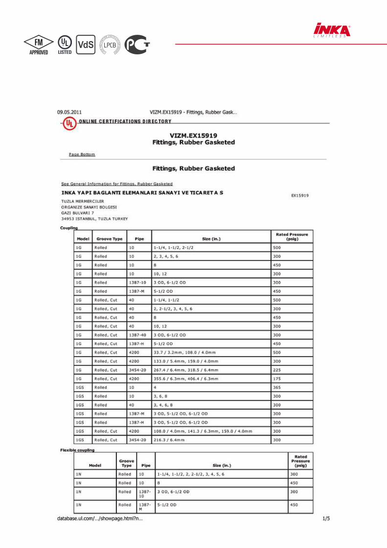
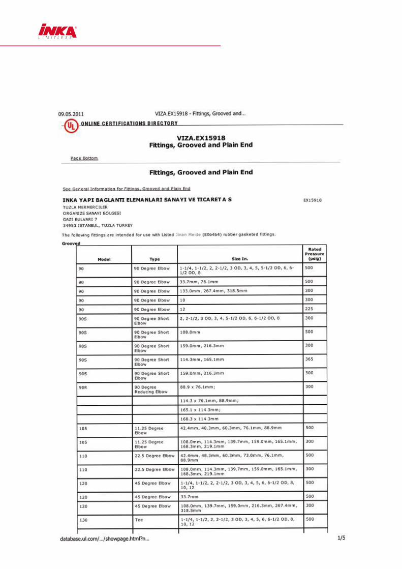
İNKA marka yivli bağlantı elemanları, UL(ABD) FM (ABD) GOST (RUSYA) VDS (ALMANYA) LPCB (İNGİLTERE) gibi bazı üstün laboratuarlar ve kuruluşlar tarafından test edilmiş ve onaylanmıştır.
Üretimi dünyanın 80 ülkesinde satılan tesisin ürünleri, Türkiye de İNKA markasıyla seçkin projelere ve yine seçkin mekanik tesisat taahhüt firmalarına ulaştırılmaktadır.
Yivli boru sistemler, eski yöntem olan kaynaklı boru sistemine göre ciddi işçilik ve bakım avantajlarını da beraberinde getirmektedir. Uygulama geleneksel yönteme göre daha hızlı uygulanır. Ayrıca yivli bağlantı elemanları bünyesindeki conta, yüksek seviyede sızdırmazlık sağlar.
Yivli bağlantı elemanları, mekanik tesisat sektörünün yanı sıra atık su ve temiz su tesisatları, sulama hatlarında, gemi tesisatları vb. alanlarda da kullanılmaktadır.
TANITIMBRIEF INTRODUCTION

“INKA” brand grooved fittings are produced by one of the biggest grooved fittings producers in the world. There is minimum 140.000tones of production yearly at developing facilities for more than 50 years.
The products can be summarized with 3 standards. These are American Standard, DIN Standard and BS Standard. The sizes are between 1/8” and 24”. The products are used in several pipelines for delivering materials such as gas, water, oil etc. Cast suntanned pipe fittings, flexible steel screwed pipe fittings and other custom made cast products are produced in the facilities.
The facilities are comply with ISO 9001 Quality Management System. In addition, there are BVQI approved certificates which are accepted in America and Britain. To increase the responsibility against environment, also ISO 14001 Environmental Management System is recognized by BVQI.
“INKA” brand grooved fittings are tested and approved by some superior laboratories like UL (USA), FM (USA), GOST (RUSSIA) VDS (GERMANY) LPCB (UK).
The products of the facilities are sold in 80 different countries and reaches to eminent Projects with eminent contractors through INKA brand in Turkey.
Grooved systems have advantages of labor and maintenance against old method of welding systems. The applications are faster than traditional methods. Moreover, the gasket at the grooved couplings provides high level of sealing. Grooved fittings are also used for waste and clean water installments, irrigation, shipbuilding industry, etc

ÜRETİM TESİSLERİ VE TEST LABORATUVARLARI
Kaplin üretim tesislerimiz; bilgi teknolojisi, makineleşme ve otomasyona yatırım yapmakta ve esas üretim biçimini
işgücü ağırlıklı olmaktan; teknoloji ağırlıklı olmaya doğru geçirmeyi
başarmıştır.
Firmamız sürdürülebilir gelişmeye bağlı kalmaktadır. Enerji tasarrufunu ve çevre
kirliliğine verilen desteği azaltmayı; en önemli görev olarak belirledik ve
çeşitli çevresel göstergelerin tüm ulusal standartları karşılamasını sağlamaktayız.
Our company invests in the information technology, standardization,
mechanization and automation process, achieved the fundamental change of the
mode of production from labor- intensive to technology-intensive.
Company adheres to the sustainable development. We include energy saving
and emission reduction the most important task, various environmental
indicators all meet the national standards.
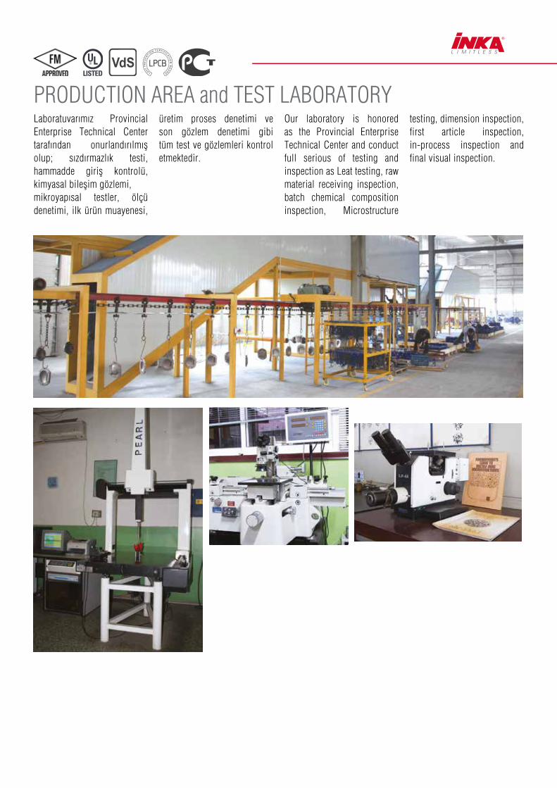
PRODUCTION AREA and TEST LABORATORYLaboratuvarımız Provincial Enterprise Technical Center tarafından onurlandırılmış olup; sızdırmazlık testi, hammadde giriş kontrolü, kimyasal bileşim gözlemi,mikroyapısal testler, ölçü denetimi, ilk ürün muayenesi,
üretim proses denetimi ve son gözlem denetimi gibi tüm test ve gözlemleri kontrol etmektedir.
Our laboratory is honored as the Provincial Enterprise Technical Center and conduct full serious of testing and inspection as Leat testing, raw material receiving inspection, batch chemical composition inspection, Microstructure
testing, dimension inspection, first article inspection, in-process inspection and final visual inspection.

SERTİFİKALAR / CERTIFICATES
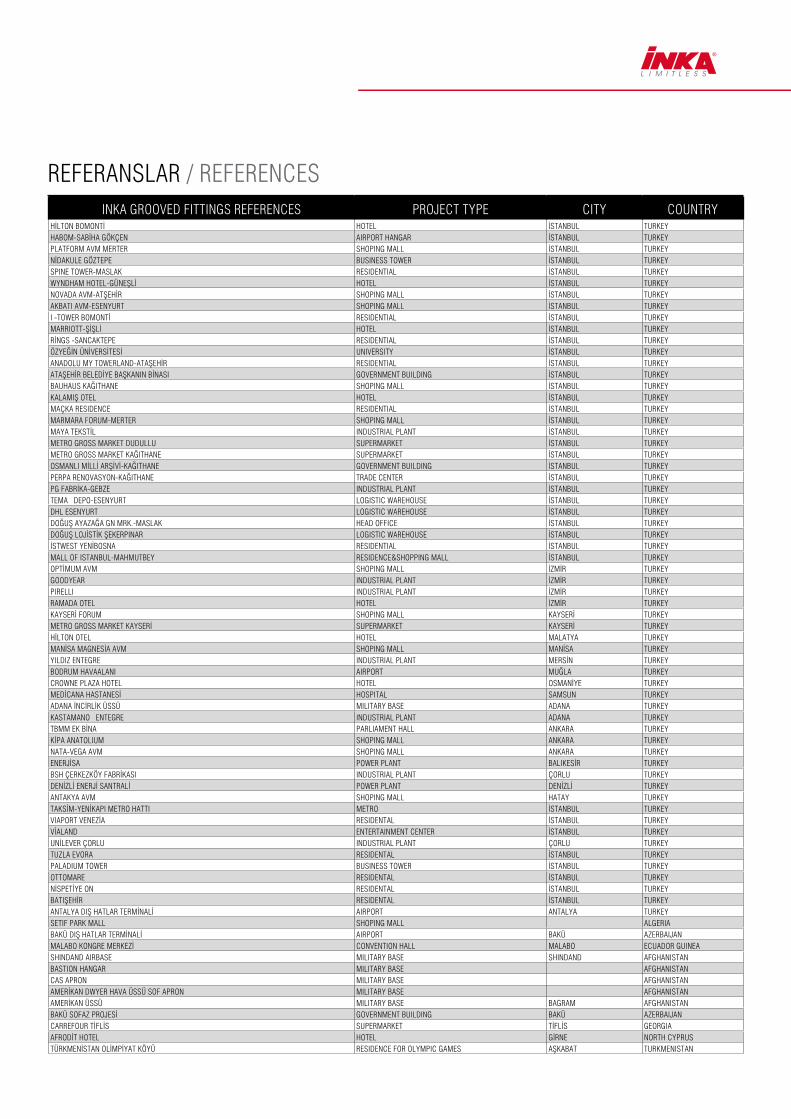
INKA GROOVED FITTINGS REFERENCES PROJECT TYPE CITY COUNTRYHİLTON BOMONTİ HOTEL İSTANBUL TURKEY HABOM-SABİHA GÖKÇEN AIRPORT HANGAR İSTANBUL TURKEY PLATFORM AVM MERTER SHOPING MALL İSTANBUL TURKEY NİDAKULE GÖZTEPE BUSINESS TOWER İSTANBUL TURKEY SPINE TOWER-MASLAK RESIDENTIAL İSTANBUL TURKEY WYNDHAM HOTEL-GÜNEŞLİ HOTEL İSTANBUL TURKEY NOVADA AVM-ATŞEHİR SHOPING MALL İSTANBUL TURKEY AKBATI AVM-ESENYURT SHOPING MALL İSTANBUL TURKEY I -TOWER BOMONTİ RESIDENTIAL İSTANBUL TURKEY MARRIOTT-ŞİŞLİ HOTEL İSTANBUL TURKEY RİNGS -SANCAKTEPE RESIDENTIAL İSTANBUL TURKEY ÖZYEĞİN ÜNİVERSİTESİ UNIVERSITY İSTANBUL TURKEY ANADOLU MY TOWERLAND-ATAŞEHİR RESIDENTIAL İSTANBUL TURKEY ATAŞEHİR BELEDİYE BAŞKANIN BİNASI GOVERNMENT BUILDING İSTANBUL TURKEY BAUHAUS KAĞITHANE SHOPING MALL İSTANBUL TURKEY KALAMIŞ OTEL HOTEL İSTANBUL TURKEY MAÇKA RESIDENCE RESIDENTIAL İSTANBUL TURKEY MARMARA FORUM-MERTER SHOPING MALL İSTANBUL TURKEY MAYA TEKSTİL INDUSTRIAL PLANT İSTANBUL TURKEY METRO GROSS MARKET DUDULLU SUPERMARKET İSTANBUL TURKEY METRO GROSS MARKET KAĞITHANE SUPERMARKET İSTANBUL TURKEY OSMANLI MİLLİ ARŞİVİ-KAĞITHANE GOVERNMENT BUILDING İSTANBUL TURKEY PERPA RENOVASYON-KAĞITHANE TRADE CENTER İSTANBUL TURKEY PG FABRİKA-GEBZE INDUSTRIAL PLANT İSTANBUL TURKEY TEMA DEPO-ESENYURT LOGISTIC WAREHOUSE İSTANBUL TURKEY DHL ESENYURT LOGISTIC WAREHOUSE İSTANBUL TURKEY DOĞUŞ AYAZAĞA GN MRK.-MASLAK HEAD OFFICE İSTANBUL TURKEY DOĞUŞ LOJİSTİK ŞEKERPINAR LOGISTIC WAREHOUSE İSTANBUL TURKEY İSTWEST YENİBOSNA RESIDENTIAL İSTANBUL TURKEY MALL OF ISTANBUL-MAHMUTBEY RESIDENCE&SHOPPING MALL İSTANBUL TURKEY OPTİMUM AVM SHOPING MALL İZMİR TURKEY GOODYEAR INDUSTRIAL PLANT İZMİR TURKEY PIRELLI INDUSTRIAL PLANT İZMİR TURKEY RAMADA OTEL HOTEL İZMİR TURKEY KAYSERİ FORUM SHOPING MALL KAYSERİ TURKEY METRO GROSS MARKET KAYSERİ SUPERMARKET KAYSERİ TURKEY HİLTON OTEL HOTEL MALATYA TURKEY MANİSA MAGNESİA AVM SHOPING MALL MANİSA TURKEY YILDIZ ENTEGRE INDUSTRIAL PLANT MERSİN TURKEY BODRUM HAVAALANI AIRPORT MUĞLA TURKEY CROWNE PLAZA HOTEL HOTEL OSMANİYE TURKEY MEDİCANA HASTANESİ HOSPITAL SAMSUN TURKEY ADANA İNCİRLİK ÜSSÜ MILITARY BASE ADANA TURKEY KASTAMANO ENTEGRE INDUSTRIAL PLANT ADANA TURKEY TBMM EK BİNA PARLIAMENT HALL ANKARA TURKEY KİPA ANATOLIUM SHOPING MALL ANKARA TURKEY NATA-VEGA AVM SHOPING MALL ANKARA TURKEY ENERJİSA POWER PLANT BALIKESİR TURKEY BSH ÇERKEZKÖY FABRİKASI INDUSTRIAL PLANT ÇORLU TURKEY DENİZLİ ENERJİ SANTRALİ POWER PLANT DENİZLİ TURKEY ANTAKYA AVM SHOPING MALL HATAY TURKEY TAKSİM-YENİKAPI METRO HATTI METRO İSTANBUL TURKEY VIAPORT VENEZİA RESIDENTAL İSTANBUL TURKEY VİALAND ENTERTAINMENT CENTER İSTANBUL TURKEY UNİLEVER ÇORLU INDUSTRIAL PLANT ÇORLU TURKEY TUZLA EVORA RESIDENTAL İSTANBUL TURKEY PALADIUM TOWER BUSINESS TOWER İSTANBUL TURKEY OTTOMARE RESIDENTAL İSTANBUL TURKEY NİSPETİYE ON RESIDENTAL İSTANBUL TURKEY BATIŞEHİR RESIDENTAL İSTANBUL TURKEY ANTALYA DIŞ HATLAR TERMİNALİ AIRPORT ANTALYA TURKEY SETIF PARK MALL SHOPING MALL ALGERIA BAKÜ DIŞ HATLAR TERMİNALİ AIRPORT BAKÜ AZERBAIJANMALABO KONGRE MERKEZİ CONVENTION HALL MALABO ECUADOR GUINEA SHINDAND AIRBASE MILITARY BASE SHINDAND AFGHANISTANBASTION HANGAR MILITARY BASE AFGHANISTANCAS APRON MILITARY BASE AFGHANISTANAMERİKAN DWYER HAVA ÜSSÜ SOF APRON MILITARY BASE AFGHANISTANAMERİKAN ÜSSÜ MILITARY BASE BAGRAM AFGHANISTANBAKÜ SOFAZ PROJESİ GOVERNMENT BUILDING BAKÜ AZERBAIJAN CARREFOUR TİFLİS SUPERMARKET TİFLİS GEORGIAAFRODİT HOTEL HOTEL GİRNE NORTH CYPRUS TÜRKMENİSTAN OLİMPİYAT KÖYÜ RESIDENCE FOR OLYMPIC GAMES AŞKABAT TURKMENISTAN
REFERANSLAR / REFERENCES
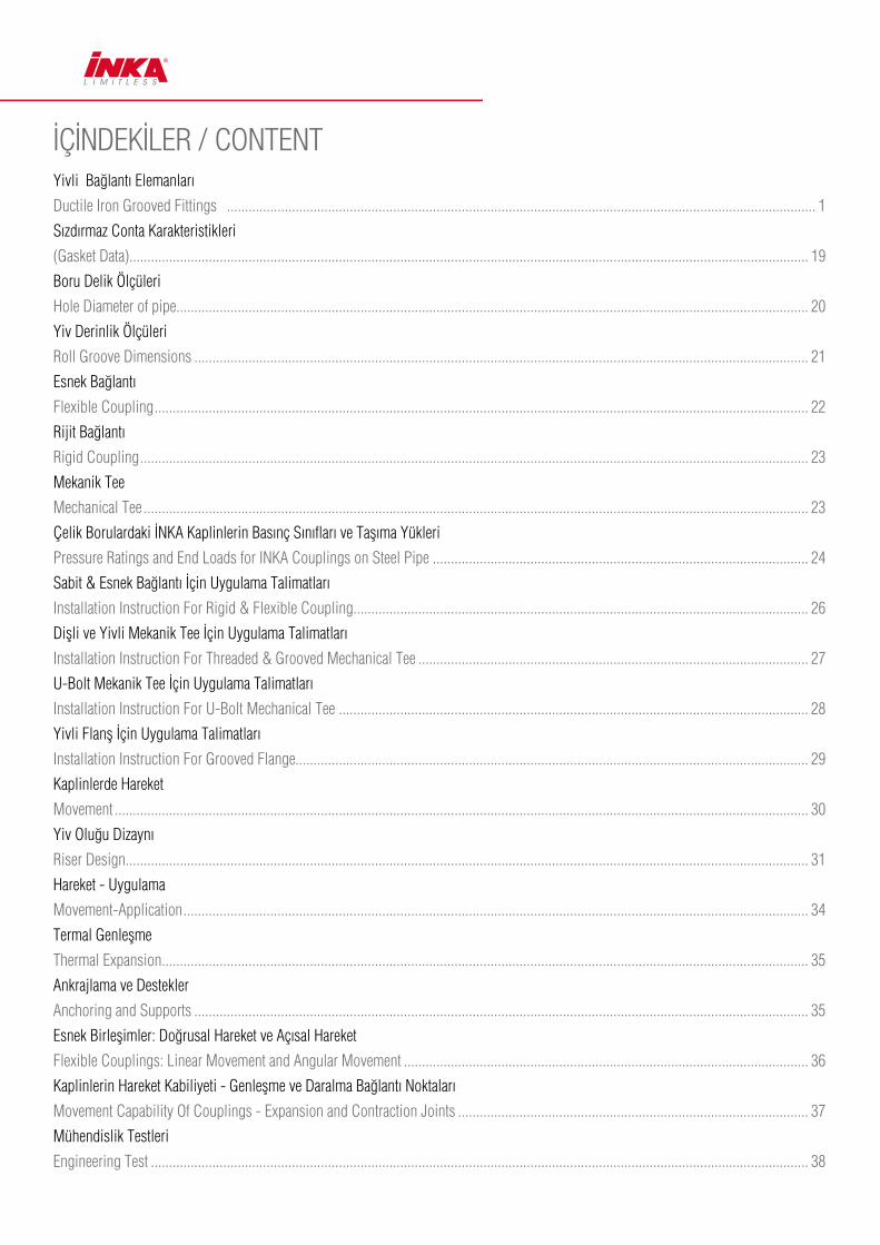
İÇİNDEKİLER / CONTENT Yivli Bağlantı Elemanları
Ductile Iron Grooved Fittings ................................................................................................................................................................... 1
Sızdırmaz Conta Karakteristikleri
(Gasket Data)............................................................................................................................................................................................ 19
Boru Delik Ölçüleri
Hole Diameter of pipe............................................................................................................................................................................... 20
Yiv Derinlik Ölçüleri
Roll Groove Dimensions .......................................................................................................................................................................... 21
Esnek Bağlantı
Flexible Coupling ..................................................................................................................................................................................... 22
Rijit Bağlantı
Rigid Coupling ......................................................................................................................................................................................... 23
Mekanik Tee
Mechanical Tee ........................................................................................................................................................................................ 23
Çelik Borulardaki İNKA Kaplinlerin Basınç Sınıfları ve Taşıma Yükleri
Pressure Ratings and End Loads for INKA Couplings on Steel Pipe ........................................................................................................ 24
Sabit & Esnek Bağlantı İçin Uygulama Talimatları
Installation Instruction For Rigid & Flexible Coupling.............................................................................................................................. 26
Diflli ve Yivli Mekanik Tee İçin Uygulama Talimatları
Installation Instruction For Threaded & Grooved Mechanical Tee ............................................................................................................ 27
U-Bolt Mekanik Tee İçin Uygulama Talimatları
Installation Instruction For U-Bolt Mechanical Tee .................................................................................................................................. 28
Yivli Flanfl İçin Uygulama Talimatları
Installation Instruction For Grooved Flange.............................................................................................................................................. 29
Kaplinlerde Hareket
Movement ................................................................................................................................................................................................ 30
Yiv Oluğu Dizaynı
Riser Design............................................................................................................................................................................................. 31
Hareket - Uygulama
Movement-Application ............................................................................................................................................................................. 34
Termal Genleşme
Thermal Expansion................................................................................................................................................................................... 35
Ankrajlama ve Destekler
Anchoring and Supports .......................................................................................................................................................................... 35
Esnek Birleflimler: Doğrusal Hareket ve Açısal Hareket
Flexible Couplings: Linear Movement and Angular Movement ................................................................................................................ 36
Kaplinlerin Hareket Kabiliyeti - Genleflme ve Daralma Bağlantı Noktaları
Movement Capability Of Couplings - Expansion and Contraction Joints ................................................................................................. 37
Mühendislik Testleri
Engineering Test ...................................................................................................................................................................................... 38

1
Yivli Bağlantı Elemanları Ductile Iron Grooved Fittings
1N
90S
180
300240N
1NR
120
3GS
321
1GS
130S
3L
1G
130
3JS
90
130R
240
Yivli Esnek Kaplin
Flexible Coupling
90° Dirsek
Light-duty 90° Elbow
Yivli İstavroz
Cross
Tapa
Cap
İç Dişli Yivli Redüksiyon
Grooved Concentric Reducer with
Female Thread
Yivli Redüksiyon Kaplin
Reducing Flexible Coupling
45° Dirsek
45° Elbow
Yivli Mekanik Tee
Light-duty Mechanical Tee
Grooved Outlet
Yivli Flanfl
Grooved Flange
Yivli Sabit (Rijit) Kaplin
Light-duty Rigid Coupling
Yivli Tee
Light-duty Tee
U-Bolt Mekanik Tee
U-Bolt Mechanical Tee
Yivli Sabit (Rijit) Kaplin
Rigid Coupling
Yivli Tee
Tee
Diflli Mekanik Tee
Light-duty Mechanical Tee
Threaded Outlet
90° Dirsek
90° Elbow
Yivli Redüksiyon Tee
Reducing Tee
Yivli Redüksiyon
Grooved Concentric Reducer
2
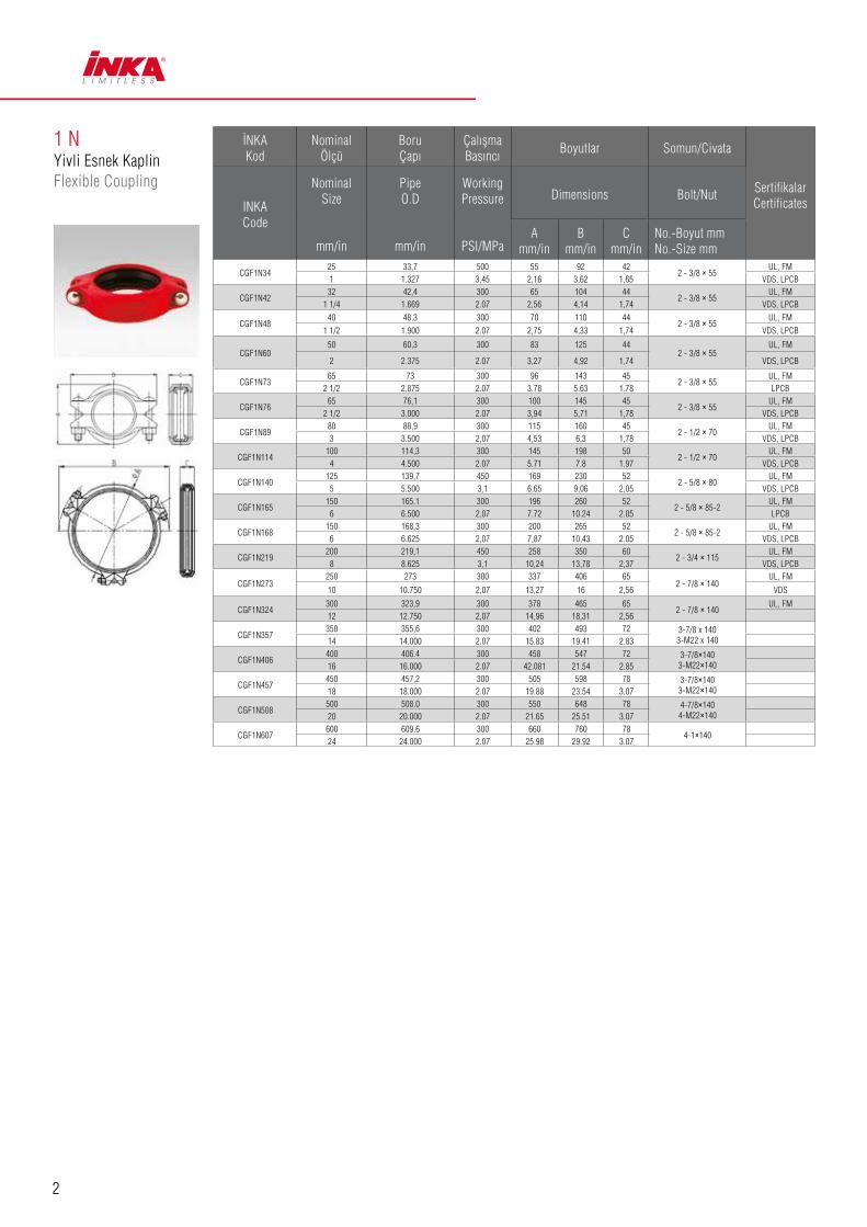
1 NYivli Esnek KaplinFlexible Coupling
İNKAKod
NominalÖlçü
BoruÇapı
ÇalışmaBasıncı
Boyutlar Somun/Civata
SertifikalarCertificatesINKA
Code
Nominal Size
mm/in
Pipe O.D
mm/in
Working Pressure
PSI/MPa
Dimensions Bolt/Nut
Amm/in
Bmm/in
Cmm/in
No.-Boyut mmNo.-Size mm
CGF1N3425 33,7 500 55 92 42
2 - 3/8 × 55UL, FM
1 1.327 3,45 2,16 3,62 1,65 VDS, LPCB
CGF1N4232 42,4 300 65 104 44
2 - 3/8 × 55UL, FM
1 1/4 1.669 2.07 2,56 4,14 1,74 VDS, LPCB
CGF1N4840 48,3 300 70 110 44
2 - 3/8 × 55UL, FM
1 1/2 1.900 2.07 2,75 4,33 1,74 VDS, LPCB
CGF1N6050 60,3 300 83 125 44
2 - 3/8 × 55UL, FM
2 2.375 2.07 3,27 4,92 1,74 VDS, LPCB
CGF1N7365 73 300 96 143 45
2 - 3/8 × 55UL, FM
2 1/2 2.875 2.07 3.78 5.63 1.78 LPCB
CGF1N7665 76,1 300 100 145 45
2 - 3/8 × 55UL, FM
2 1/2 3.000 2.07 3,94 5,71 1,78 VDS, LPCB
CGF1N8980 88,9 300 115 160 45
2 - 1/2 × 70UL, FM
3 3.500 2,07 4,53 6,3 1,78 VDS, LPCB
CGF1N114100 114,3 300 145 198 50
2 - 1/2 × 70UL, FM
4 4.500 2.07 5.71 7.8 1.97 VDS, LPCB
CGF1N140125 139,7 450 169 230 52
2 - 5/8 × 80UL, FM
5 5.500 3,1 6,65 9,06 2,05 VDS, LPCB
CGF1N165150 165.1 300 196 260 52
2 - 5/8 × 85-2UL, FM
6 6.500 2,07 7.72 10.24 2.05 LPCB
CGF1N168150 168,3 300 200 265 52
2 - 5/8 × 85-2UL, FM
6 6.625 2,07 7,87 10,43 2.05 VDS, LPCB
CGF1N219200 219,1 450 258 350 60
2 - 3/4 × 115UL, FM
8 8.625 3,1 10,24 13,78 2,37 VDS, LPCB
CGF1N273250 273 300 337 406 65
2 - 7/8 × 140UL, FM
10 10.750 2,07 13,27 16 2,56 VDS
CGF1N324300 323,9 300 378 465 65
2 - 7/8 × 140UL, FM
12 12.750 2,07 14,96 18,31 2,56
CGF1N357350 355,6 300 402 493 72 3-7/8 x 140
3-M22 x 14014 14.000 2.07 15.83 19.41 2.83
CGF1N406400 406.4 300 458 547 72 3-7/8×140
3-M22×14016 16.000 2.07 42.081 21.54 2.85
CGF1N457450 457,2 300 505 598 78 3-7/8×140
3-M22×14018 18.000 2.07 19.88 23.54 3.07
CGF1N508500 508.0 300 550 648 78 4-7/8×140
4-M22×14020 20.000 2.07 21.65 25.51 3.07
CGF1N607600 609.6 300 660 760 78
4-1×14024 24.000 2.07 25.98 29.92 3.07

3
1 NRYivli Redüksiyon KaplinReducing Flexible Coupling
İNKA Kod
NominalÖlçü
BoruÇap
Çal›flmaBasıncı
Boyutlar Somun/Civata
SertifikalarCertificatesINKA
Code
Nominal Size
mm/in
PipeO.D
mm/in
Working Pressure
PSI/MPa
Dimensions Bolt/Nut
Amm/in
Bmm/in
Cmm/in
No.-Boyut mmNo.-Size mm
CGF1NR604850 x 40 60.3 x 48.3 300 86 125 44
2 - 3/8 x 55UL, FM
2 x 11/2 2.375 x 1.900 2,07 3,39 4,93 1,74 LPCB
CGF1NR733465 x 25 73,0 x 33,7 300 100 138 45 2 - 3/8 x 55
UL, FM
2 1/2 x 1 2.875 x 1.327 2,07 3,94 5,44 1,78
CGF1NR736065 x 50 73.0 x 60.3 300 100 138 45
2 - 3/8 X 55UL, FM
2 ½ x 2 2.875 x 2.375 2,07 3,94 5,43 1,78 LPCB
CGF1NR763465 x 25 76.1 x 33.7 300 102 140 45
2 - 3/8 x 55UL, FM
2 1/2 x 1 3.000 x 1.327 2,07 4,02 5,51 1,78
CGF1NR764865 x 40 76.1 x 48.3 300 102 140 45
2 - 3/8 x 55UL, FM
21/2 x 2 3.000 x 1.900 2,07 4,02 5,51 1,78 LPCB
CGF1NR766065 x 50 76.1 x 60.3 300 102 144 45
2 - 3/8 x 55UL, FM
2 ½ x 2 3.000 x 2.375 2,07 4,02 5,67 1,78 VDS, LPCB
CGF1NR736065 x 50 73.0 x 60.3 300 100 138 45
2 - 3/8 X 55UL, FM
2 ½ x 2 2.875 x 2.375 2,07 3,94 5,43 1,78 LPCB
CGF1NR893480 x 25 88.9 x 33.7 300 115 168 46
2 - 1/2 x 70UL, FM
3 x 1 3.500 x 1.327 2,07 4,53 6,61 1,81
CGF1NR896080 x 50 88.9 x 60.3 300 115 168 46
2 - 1/2 x 70UL, FM
3 x 2 3.500 x 2.375 2,07 4,53 6,61 1,81 VDS, LPCB
CGF1NR897380 x 65 88.9 x 73.0 300 115 168 46
2 - 1/2 x 70UL, FM
3 x 2 1/2 3.500 x 2.875 2,07 4,53 6,61 1,81 LPCB
CGF1NR897680 x 65 88.9 x 76.1 300 115 172 46
2 - 1/2 x 70UL, FM
3 x 2 1/2 3.500 x 3.000 2,07 4,53 6,77 1,81 VDS, LPCB
CGF1NR11434100 x 25 114.3 x 33.7 300 144 198 50
2 - 1/2 x 70UL, FM
4 x 1 4.500 x 1.327 2,07 5,67 7,8 1,97
CGF1NR11460100 x 50 114.3 x 60.3 300 144 198 50
2 - 1/2 x 70UL, FM
4 x 2 4.500 x 2.375 2,07 5,67 7,8 1,97 VDS, LPCB
CGF1NR11473100 x 65 114.3 x 73.0 300 144 198 50
2 - 1/2 x 70UL, FM
4 x 21/2 4.500 x 2.875 2,07 5,67 7,8 1,97 VDS, LPCB
CGF1NR11476100 x 65 114.3 x 76.1 300 144 198 50
2 - 1/2 x 70UL, FM
4 x 21/2 4.500 x 2.875 2,07 5,67 7,8 1,97 LPCB
CGF1NR11489100 x 80 114.3 x 88.9 300 148 198 50
2 - 1/2 x 70UL, FM
4 x 3 4.500 x 3.500 2,07 5,83 7,8 1,97 VDS, LPCB
CGF1NR165114150 x 100 165.1 x 114.3 300 197 260 51
2 - 5/8 x 85UL,FM
6 x 4 6.500 x 4.500 2,07 7,75 10,24 2,01 LPCB
CGF1NR168114150 x 100 168.3 x 114.3 300 202.5 268 52.5
2 - 5/8 x 85UL, FM
6 x 4 6.625 x 4.500 2,07 7,97 10,55 2,07 VDS, LPCB
CGF1NR219165200 x 150 219.1 x 165.1 300 257 335 60
2 - 3/4 x 115UL, FM
8 x 6 8.625 x 6.500 2,07 10,12 13,19 2,36 LPCB
CGF1NR219168200 x 150 219.1 x 168.3 300 260 338 60
2 - 3/4 x 115UL, FM
8 x 6 8.625 x 6.625 2,07 10,24 13.31 2.36 LPCB

4
1 GYivli Sabit (Rijit) KaplinRigid Coupling
İNKAKod
NominalÖlçü
BoruÇapı
ÇalışmaBasıncı
Boyutlar Somun/Civata
SertifikalarCertificatesINKA
Code
Nominal Size
mm/in
Pipe O.D
mm/in
Working Pressure
PSI/MPa
Dimensions Bolt/Nut
Amm/in
Bmm/in
Cmm/in
No.-Boyut mmNo.-Size mm
CGF1G3425 33,7 500 59 100 44
2 - 3/8 x 55UL, FM
1 1.327 3,45 2,33 3,94 1,74 VDS, LPCB
CGF1G4232 42,4 500 66 109 45
2 - 3/8 x 55UL, FM
1 1/4 1.669 3,45 2,6 4,13 1,78 VDS, LPCB
CGF1G4840 48,3 500 72 115 45
2 - 3/8 x 55UL, FM
1 1/2 1.900 3,45 2,84 4,53 1,78 VDS, LPCB
CGF1G6050 60,3 300 85 131 45
2 - 3/8 x 55UL, FM
2 2.375 2,07 3,35 5,16 1,78 VDS, LPCB
CGF1G7365 73 500 98 145 45
2 - 3/8 x 55UL, FM
2 1/2 2.875 3,45 3,86 5,71 1,78 LPCB
CGF1G7665 76,1 300 101 147 45
2 - 3/8 x 55UL, FM
2 1/2 3.000 2,07 3,98 5,78 1,77 VDS, LPCB
CGF1G273250 273 300 327 420 63
2 - 7/8 x 125UL, FM
10 10.750 2,07 12,88 16,54 2,48 VDS
CGF1G324300 323,9 300 378 466 63
2 - 7/8 x 140UL, FM
12 12.750 2,07 14,88 18,35 2,48
1 GSYivli Sabit (Rijit) KaplinLight-duty Rigid Coupling
İNKAKod
NominalÖlçü
BoruÇapı
ÇalışmaBasıncı
Boyutlar Somun/Civata
SertifikalarCertificatesINKA
Code
Nominal Size
mm/in
Pipe O.D
mm/in
Working Pressure
PSI/MPa
Dimensions Bolt/Nut
Amm/in
Bmm/in
Cmm/in
No.-Boyut mmNo.-Size mm
CGF1GS8980 88,9 300 114 160 45
2 - 3/8 x 55UL, FM
3 3.500 2,07 4,5 6,3 1,78 VDS, LPCB
CGF1GS114100 114,3 300 140 192 50
2 - 1/2 x 70UL, FM
4 4.500 2,07 5,51 7,56 1,97 VDS, LPCB
CGF1GS140125 139,7 300 168 225 50
2 - 1/2 x 75UL, FM
5 5.500 2,07 6,62 8,86 1,97 LPCB
CGF1GS165150 165,1 300 195 250 50
2 - 1/2 x 75UL, FM
6 6.500 2,07 7,68 9,84 1,97 LPCB
CGF1GS168150 168 300 200 255 50
2 - 1/2 x 75UL, FM
6 6.625 2,07 7,87 10,04 1,97 LPCB
CGF1GS219200 219,1 300 255 324 58
2 - 5/8 x 85UL, FM
8 8.625 2,07 10,05 12,76 2,28 LPCB

5
9090° Dirsek90° Elbow
İNKAKod
NominalÖlçü
BoruÇapı
Çalışma 90
SertifikalarCertificatesINKA
Code
Nominal Size
mm/in
Pipe O.D
mm/in
Working PressurePSI/MPa
90
90°)Elbow) L
CGF903425 33,7 500 57 UL, FM1 1.315 3,45 2,24 VDS, LPCB
CGF904232 42,4 500 70 UL, FM
1 1/4 1.660 3,45 2,75 VDS, LPCB
CGF904840 48,3 500 70 UL, FM
1 1/2 1.900 3,45 2,75 VDS, LPCB
CGF90273250 273 500 229 UL, FM10 10.750 3,45 9 VDS
CGF90324300 323,9 500 254 UL, FM12 12.750 3,45 10 VDS
CGF90356350 355.6 300 28014 14.000 2.07 11.02
CGF90406400 406.4 300 30516 16.000 2.07 12.00
CGF90457450 457.2 300 39418 18.000 2.07 15.50
CGF90508500 508.0 300 43820 20.000 2.07 17.25
CGF90607600 609.6 300 50824 24.000 2.07 20.00
90 S90° DirsekLight-duty 90° Elbow
İNKAKod
NominalÖlçü
BoruÇapı
ÇalışmaBasıncı
90S90° Dirsek
SertifikalarCertificatesINKA
Code
Nominal Size
mm/in
Pipe O.D
mm/in
Working Pressure
PSI/MPa
90S
(90° Elbow) L
CGF90S6050 60,3 300 70 UL, FM2 2.375 2,07 2,75 VDS, LPCB
CGF90S7365 73 300 76 UL, FM
2 1/2 2.875 2,07 3.00
CGF90S7665 76,1 300 76 UL, FM
2 1/2 3.000 2,07 3 VDS, LPCB
CGF90S8980 88,9 300 85,5 UL, FM
3 3.500 2,07 3,37 VDS, LPCB
CGF90S114100 114,3 300 101 UL, FM
4 4.500 2,07 3,98 VDS, LPCB
CGF90S140125 139,7 300 124 UL, FM
5 5.500 2,07 4,88 VDS, LPCB
CGF90S165150 165,1 300 140 UL, FM
6 6.500 2,07 5,5 LPCB
CGF90S168150 168 300 140 UL, FM
6 6.625 2,07 5,5 VDS, LPCB
CGF90S219200 219,1 300 165 UL, FM
8 8.625 2,07 6.5 VDS, LPCB

6
12045° Dirsek45° Elbow
İNKA Kod
Nominal Ölçü
Boru Çapı
ÇalışmaBasıncı
Boyutlar
SertifikalarCertificatesINKA
Code
Nominal Size
mm/in
Pipe O.D
mm/in
Working Pressure
PSI/MPa
Dimensions
Lmm/in
CGF1203425 33,7 500 44,5 UL, FM1 1.315 3,45 1,75 VDS, LPCB
CGF1204232 42,4 500 44,5 UL, FM
1 1/4 1.660 3,45 1,75 VDS, LPCB
CGF1204840 48,3 500 44,5 UL, FM
1 1/2 1.900 3,45 1,75 VDS, LPCB
CGF1206050 60,3 500 51 UL, FM
2 2.375 3,45 2 VDS, LPCB
CGF1207365 73 500 57 UL, FM
2 1/2 2.875 3,45 2,24
CGF1207665 76,1 500 57 UL, FM
2 1/2 3.000 3,45 2,24 VDS, LPCB
CGF1208980 88,9 500 63,5 UL, FM3 3.500 3,45 2,5 VDS, LPCB
CGF120114100 114,3 500 76 UL, FM
4 4.500 3,45 3 VDS, LPCB
CGF120140125 139,7 500 82,5 UL, FM
5 5.500 3,45 3,25 VDS, LPCB
CGF120165150 165,1 500 89 UL, FM
6 6.500 3,45 3,5 LPCB
CGF120168150 168 500 89 UL, FM
6 6.625 3,45 3,5 VDS, LPCB
CGF120219200 219,1 500 108 UL, FM
8 8.625 3,45 4,25 VDS, LPCB
CGF120273250 273 500 120,5 UL, FM10 10.750 3,45 4,75 VDS
CGF120324300 323,9 500 133 UL, FM12 12.750 3,45 5,25 VDS
CGF120356350 355.6 300 15214 14.000 2.07 6.00
CGF120406400 406.4 300 18416 16.000 2.07 7.25
CGF120458450 457.2 300 20318 18.000 2.07 8.00
CGF120508500 508.0 300 229.020 20.000 2.07 9.00
CGF120610600 609.6 300 28024 24.000 2.07 11.00
130Yivli TeeTee
İNKA Kod
Nominal Ölçü
Boru Çapı
ÇalışmaBasıncı
130
SertifikalarCertificatesINKA
Code
Nominal Size
mm/in
Pipe O.D
mm/in
BasıncıWorking Pressure
PSI/MPa
130
L
CGF1303425 33,7 500 57 UL, FM1 1.315 3,45 2,24 VDS, LPCB
CGF1304232 42,4 500 70 UL, FM
1 1/4 1.660 3,45 2,75 VDS, LPCB
CGF1304840 48,3 500 70 UL, FM
1 1/2 1.900 3,45 2,75 VDS, LPCB
CGF130273250 273 500 229 UL, FM10 10.750 3,45 9 VDS
CGF130324300 323,9 500 254 UL, FM12 12.750 3,45 10 VDS

7
130 SYivli TeeLight-duty Tee
İNKA Kod
Nominal Ölçü
Boru Çapı
ÇalışmaBasıncı
130S
SertifikalarCertificatesINKA
Code
Nominal Size
mm/in
Pipe O.D
mm/in
BasıncıWorking Pressure
PSI/MPa
130S
L
CGF130S6050 60,3 300 70 UL, FM2 2.375 2,07 2,75 VDS, LPCB
CGF130S7365 73 300 76 UL, FM
2 1/2 2.875 2,07 3
CGF130S7665 76,1 300 76 UL, FM
2 1/2 3.000 2,07 3 VDS, LPCB
CGF130S8980 88,9 300 85,5 UL, FM3 3.500 2,07 3,37 VDS, LPCB
CGF130S114100 114,3 300 101 UL, FM
4 4.500 2,07 3,98 VDS, LPCB
CGF130S140125 139,7 300 124 UL, FM
5 5.500 2,07 4,88 VDS, LPCB
CGF130S165150 165,1 300 140 UL, FM
6 6.500 2,07 5,5 LPCB
CGF130S168150 168 300 140 UL, FM
6 6.625 2,07 5,5 VDS, LPCB
CGF130S219200 219,1 300 175 UL, FM
8 8.625 2,07 6,89 VDS, LPCB
CGF130356350 355.6 300 28014 14.000 2.07 11.02
CGF130407400 406.4 300 30516 16.000 2.07 12.00
CGF130458450 457.2 300 39418 18.000 2.07 15.50
CGF130508500 508.0 300 43820 20.000 2.07 17.25
CGF130610600 609.6 300 50824 24.000 2.07 20.00
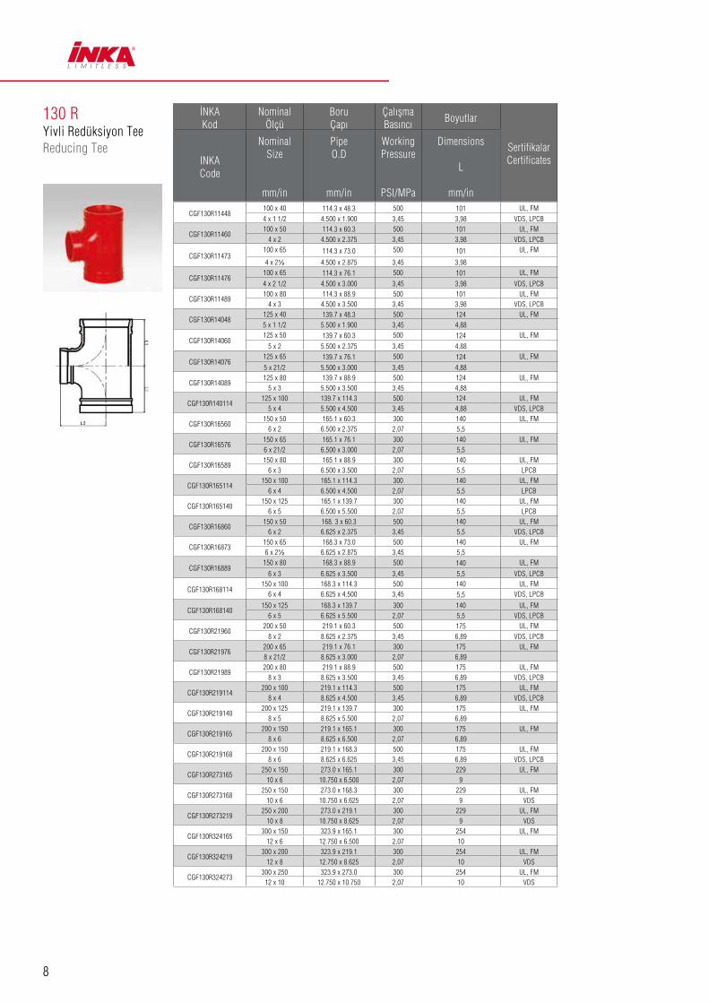
130 RYivli Redüksiyon TeeReducing Tee
İNKA Kod
Nominal Ölçü
Boru Çapı
ÇalışmaBasıncı
Boyutlar
SertifikalarCertificatesINKA
Code
Nominal Size
mm/in
Pipe O.D
mm/in
Working Pressure
PSI/MPa
Dimensions
L
mm/in
GGF130R603450 x 25 60.3 x 33.7 500 70 UL, FM
2 x 1 2.375 x 1.315 3,45 2,75 VDS, LPCB
CGF130R604850 x 40 60.3 x 48.3 500 70 UL, FM
2 x 1 1/2 2.375 x 1.900 3,45 2,75 VDS, LPCB
CGF130R734865 x 40 73.0 x 48.3 500 76 UL, FM
2½ x 1½ 2.875 x 1.900 3,45 3.00
CGF130R736065 x 50 73.0 x 60.3 500 69 UL, FM2½ x 2 2.875 x 2.375 3,45 2,72
CGF130R764265 x 32 76.1 x 42.4 500 76 UL, FM
2 1/2 x 1 1/4 3.000 x 1.660 3,45 3
CGF130R764865 x 40 76.1 x 48.3 500 76 UL, FM
2 1/2 x 1 1/2 3.000 x 1.900 3,45 3 VDS, LPCB
CGF130R766065 x 50 76.1 x 60.3 500 69 UL, FM21/2 x 2 3.000 x 2.375 3,45 2,72 VDS, LPCB
CGF130R893480 x 25 88.9 x 33.7 500 108 UL, FM
3 x 1 3.500 x 1.315 3,45 4,25 VDS, LPCB
CGF130R894280 x 32 88.9 x 42.4 500 85,5 UL, FM
3 x 1 1/4 3.500 x 1.660 3,45 3,37
CGF130R894880 x 40 88.9 x 48.3 500 85,5 UL, FM
3 x 1 1/2 3.500 x 1.900 3,45 3,37 VDS, LPCB
CGF130R896080 x 50 88.9 x 60.3 500 85,5 UL, FM
3 x 2 3.500 x 2.375 3,45 3,37 VDS, LPCB
CGF130R897380 x 65 88.9 x 73.0 500 85,5 UL, FM
3 x 2½ 3.500 x 2.875 3,45 3,37
CGF130R897680 x 65 88.9 x 76.1 500 85,5 UL, FM
3 x 2 1/2 3.500 x 3.000 3,45 3,37 VDS, LPCB
CGF130R11434100 x 25 114.3 x 33.7 500 101 UL, FM
4 x 1 4.500 x 1.315 3,45 3,98 VDS, LPCB
8
CGF130R11448100 x 40 114.3 x 48.3 500 101 UL, FM
4 x 1 1/2 4.500 x 1.900 3,45 3,98 VDS, LPCB
CGF130R11460100 x 50 114.3 x 60.3 500 101 UL, FM
4 x 2 4.500 x 2.375 3,45 3,98 VDS, LPCB
CGF130R11473100 x 65 114.3 x 73.0 500 101 UL, FM
4 x 2½ 4.500 x 2.875 3,45 3,98
CGF130R11476100 x 65 114.3 x 76.1 500 101 UL, FM
4 x 2 1/2 4.500 x 3.000 3,45 3,98 VDS, LPCB
CGF130R11489100 x 80 114.3 x 88.9 500 101 UL, FM
4 x 3 4.500 x 3.500 3,45 3,98 VDS, LPCB
CGF130R14048125 x 40 139.7 x 48.3 500 124 UL, FM
5 x 1 1/2 5.500 x 1.900 3,45 4,88
CGF130R14060125 x 50 139.7 x 60.3 500 124 UL, FM
5 x 2 5.500 x 2.375 3,45 4,88
CGF130R14076125 x 65 139.7 x 76.1 500 124 UL, FM
5 x 21/2 5.500 x 3.000 3,45 4,88
CGF130R14089125 x 80 139.7 x 88.9 500 124 UL, FM
5 x 3 5.500 x 3.500 3,45 4,88
CGF130R140114125 x 100 139.7 x 114.3 500 124 UL, FM
5 x 4 5.500 x 4.500 3,45 4,88 VDS, LPCB
CGF130R16560150 x 50 165.1 x 60.3 300 140 UL, FM
6 x 2 6.500 x 2.375 2,07 5,5
CGF130R16576150 x 65 165.1 x 76.1 300 140 UL, FM6 x 21/2 6.500 x 3.000 2,07 5,5
CGF130R16589150 x 80 165.1 x 88.9 300 140 UL, FM
6 x 3 6.500 x 3.500 2,07 5,5 LPCB
CGF130R165114150 x 100 165.1 x 114.3 300 140 UL, FM
6 x 4 6.500 x 4.500 2,07 5,5 LPCB
CGF130R165140150 x 125 165.1 x 139.7 300 140 UL, FM
6 x 5 6.500 x 5.500 2,07 5,5 LPCB
CGF130R16860150 x 50 168. 3 x 60.3 500 140 UL, FM
6 x 2 6.625 x 2.375 3,45 5,5 VDS, LPCB
CGF130R16873150 x 65 168.3 x 73.0 500 140 UL, FM6 x 2½ 6.625 x 2.875 3,45 5,5
CGF130R16889150 x 80 168.3 x 88.9 500 140 UL, FM
6 x 3 6.625 x 3.500 3,45 5,5 VDS, LPCB
CGF130R168114150 x 100 168.3 x 114.3 500 140 UL, FM
6 x 4 6.625 x 4.500 3,45 5,5 VDS, LPCB
CGF130R168140150 x 125 168.3 x 139.7 300 140 UL, FM
6 x 5 6.625 x 5.500 2,07 5,5 VDS, LPCB
CGF130R21960200 x 50 219.1 x 60.3 500 175 UL, FM
8 x 2 8.625 x 2.375 3,45 6,89 VDS, LPCB
CGF130R21976200 x 65 219.1 x 76.1 300 175 UL, FM8 x 21/2 8.625 x 3.000 2,07 6,89
CGF130R21989200 x 80 219.1 x 88.9 500 175 UL, FM
8 x 3 8.625 x 3.500 3,45 6,89 VDS, LPCB
CGF130R219114200 x 100 219.1 x 114.3 500 175 UL, FM
8 x 4 8.625 x 4.500 3,45 6,89 VDS, LPCB
CGF130R219140200 x 125 219.1 x 139.7 300 175 UL, FM
8 x 5 8.625 x 5.500 2,07 6,89
CGF130R219165200 x 150 219.1 x 165.1 300 175 UL, FM
8 x 6 8.625 x 6.500 2,07 6,89
CGF130R219168200 x 150 219.1 x 168.3 500 175 UL, FM
8 x 6 8.625 x 6.625 3,45 6,89 VDS, LPCB
CGF130R273165250 x 150 273.0 x 165.1 300 229 UL, FM
10 x 6 10.750 x 6.500 2,07 9
CGF130R273168250 x 150 273.0 x 168.3 300 229 UL, FM
10 x 6 10.750 x 6.625 2,07 9 VDS
CGF130R273219250 x 200 273.0 x 219.1 300 229 UL, FM
10 x 8 10.750 x 8.625 2,07 9 VDS
CGF130R324165300 x 150 323.9 x 165.1 300 254 UL, FM
12 x 6 12.750 x 6.500 2,07 10
CGF130R324219300 x 200 323.9 x 219.1 300 254 UL, FM
12 x 8 12.750 x 8.625 2,07 10 VDS
CGF130R324273300 x 250 323.9 x 273.0 300 254 UL, FM
12 x 10 12.750 x 10.750 2,07 10 VDS
130 RYivli Redüksiyon TeeReducing Tee
İNKA Kod
Nominal Ölçü
Boru Çapı
ÇalışmaBasıncı
Boyutlar
SertifikalarCertificatesINKA
Code
Nominal Size
mm/in
Pipe O.D
mm/in
Working Pressure
PSI/MPa
Dimensions
L
mm/in

9
180Yivli İstavrozCross
180 R Yivli Redüksiyon İstavrozReducing Cross
İNKAKod
NominalÖlçü
BoruÇapı
ÇalışmaBasıncı
Boyutlar
SertifikalarCertificatesINKA
Code
Nominal Size
mm/in
Pipe O.D
mm/in
Working Pressure
PSI/MPa
Dimensions
L
mm/in
CGF1804232 42,4 500 70 UL, FM
1 1/4 1.660 3,45 2,75 VDS, LPCB
CGF1804840 48,3 500 70 UL, FM
1 1/2 1.900 3,45 2,75 VDS, LPCB
CGF1806050 60,3 500 70 UL, FM
2 2.375 3,45 2,75 VDS, LPCB
CGF1807365 73 500 76 UL, FM
2 1/2 2.875 3,45 3
CGF1807665 76,1 500 76 UL, FM
2 1/2 3.000 3,45 3 VDS, LPCB
CGF1808980 88,9 500 85,5 UL, FM
3 3.500 3,45 3,37 VDS, LPCB
CGF180114100 114,3 500 101 UL, FM
4 4.500 3,45 3,98 VDS, LPCB
CGF180140125 139,7 500 124 UL, FM
5 5.500 3,45 4,88 VDS, LPCB
CGF180165150 165,1 500 140 UL, FM
6 6.500 3,45 5,5 LPCB
CGF180168150 168,3 500 140 UL, FM
6 6.625 3,45 5,5 VDS, LPCB
CGF180219200 219,1 500 175 UL, FM
8 8.625 3,45 6,89 VDS, LPCB
CGF180273250 273 500 229 UL, FM10 10.750 3,45 9 VDS
CGF180324300 323,9 500 254 UL, FM
12 12.750 3,45 10 VDS
İNKA Kod
Nominal Ölçü
Boru Çapı
ÇalışmaBasıncı
Boyutlar Boyutlar
SertifikalarCertificatesINKA
Code
Nominal Size
mm/in
Pipe O.D
mm/in
Working Pressure
PSI/MPa
Dimensions
L1
mm/in
Dimensions
L2
mm/in
CGF180R766065 x 50 76.1 x 60.3 500 76 76
2 1/2 x 2 3.000 x 2.375 3,45 3,00 3,00
CGF180R896080 x 50 88.9 x 60.3 500 85.5 85.5 UL, FM
3 x 2 3.500 x 2.375 3,45 3,37 3,37
CGF180R11460100 x 50 114.3 x 60.3 500 101 101 UL, FM
4 x 2 4.500 x 2.375 3,45 3,98 3,98
CGF180R11489100 x 80 114.3 x 88.9 500 101 101 UL, FM
4 x 3 4.500 x 3.500 3,45 3,98 3,98
CGF180R16560150 x 50 165.1 x 60.3 500 140 140 UL, FM
6 x 2 6.500 x 2.375 3,45 5,5 5,5
CGF180R16589150 x 80 165.1 x 88.9 500 140 140 UL, FM
6 x 3 6.500 x 3.500 3,45 5,5 5,5
CGF180R16860150 x 50 168 x 60.3 500 140 140
6 x 2 6.625 x 2.375 3,45 5,5 5,5

10
3GSYivli Mekanik TeeLight-duty Mechanical Tee Grooved Outlet
İNKA Kod
Nominal Ölçü
Boru Çapı
Çalışma Basıncı
DelikDiagonal›
BoyutlarCivata
No
SertifikalarCertificatesINKA
Code
Nominal Size
mm/in
Pipe O.D
mm/in
Working Pressure
PSI/MPa
Hole Dia
mm/in+1.6.0/+0.063.0
DimensionsBolt Size
A B C D
CGF3GS763465 x 25 76.1 x 33.7 300 38 137 71 78 49,5
1/2 x 70 UL, FM76.1 x 1 3.000 x 1.315 2,07 1,5 5,39 2,8 3,07 1,95
CGF3GS764265 x 32 76.1 x 42.4 300 51 137 84,5 78 49,5
1/2 x 70 UL, FM76.1 x 11/4 3.000 x 1.660 2,07 2 5,39 3,33 3,07 1,95
CGF3GS764865 x 40 76.1 x 48.3 300 51 137 84,5 78 49,5
1/2 x 70 UL, FM76.1 x 11/2 3.000 x 1.900 2,07 2 5,39 3,33 3,07 1,95
CGF3GS893480 x 25 88.9 x 33.7 300 38 150 71 84 55,5
1/2 x 75 UL, FM3 x 1 3.500 x 1.315 2,07 1,5 5,91 2,8 3,31 2,19
CGF3GS894280 x 32 88.9 x 42.4 300 51 150 84,5 84 55,5
1/2 x 75 UL, FM3 x 11/4 3.500 x 1.660 2,07 2 5,91 3,33 3,31 2,19
CGF3GS894880 x 40 88.9 x 48.3 300 51 150 84,5 84 55,5
1/2 x 75 UL, FM3 x 11/2 3.500 x 1.900 2,07 2 5,91 3,33 3,31 2,19
CGF3GS896080 x 50 88.9 x 60.3 300 64 150 98 84 55,5
1/2 x 75 UL, FM3 x 2 3.500 x 2.375 2,07 2,5 5,91 3,86 3,31 2,19
CGF3GS11434100 x 25 114.3 x 33.7 300 38 178 77,5 98 67,5
1/2 x 75 UL, FM4 x 1 4.500 x 1.315 2,07 1,5 7,01 3,05 3,86 2,66
CGF3GS11448100 x 40 114.3 x 48.3 300 51 178 88 98 67,5
1/2 x 75 UL, FM4 x 11/2 4.500 x 1.900 2,07 2 7,01 3,46 3,86 2,66
CGF3GS11460100 x 50 114.3 x 60.3 300 64 178 103,5 98 67,5
1/2 x 75 UL, FM4 x 2 4.500 x 2.375 2,07 2,5 7,01 4,07 3,86 2,66
CGF3GS11473100 x 65 114.3 x 73.0 300 70 178 103,5 98 67,5
1/2 x 75 UL, FM4 x 2½ 4.500 x 2.875 2,07 2,75 7,01 4,07 3,86 2,66
CGF3GS11476100 x 65 114.3 x 76.1 300 70 178 103,5 98 67,5
1/2 x 75 UL, FM4 x 76.1 4.500 x 3.000 2,07 2,75 7,01 4,07 3,86 2,66
CGF3GS11489100 x 80 114.3 x 88.9 300 89 178 124 98 67,5
1/2 x 75 UL, FM4 x 3 4.500 x 3.500 2,07 3,5 7,01 4,88 3,86 2,66
CGF3GS14060125 x 50 139.7 x 60.3 300 64 210 110 113 82
5/8 x 85 UL, FM139.7 x 2 5.500 x 2.375 2,07 2,5 8,27 4,33 4,45 3,23
CGF3GS14076125 x 65 139.7 x 76.1 300 70 210 110 113 82
5/8 x 85 UL, FM139.7 x 76.1 5.500 x 3.000 2,07 2,75 8,27 4,33 4,45 3,23
CGF3GS14089125 x 80 139.7 x 88.9 300 89 210 130 113 82
5/8 x 85 UL, FM139.7 x 3 5.500 x 3.500 2,07 3,5 8,27 5,12 4,45 3,23
CGF3GS140114125 x 100 139.7 x 114.3 175 114 210 153 115 82
5/8 x 85 UL, FM139.7 x 4 5.500 x 4.500 1,21 4,5 8,27 6,02 4,52 3,23
CGF3GS16560150 x 50 165.1 x 60.3 300 64 235 110 124,5 94,5
5/8 x 105 UL, FM165.1 x 2 6.500 x 2.375 2,07 2,5 9,25 4,33 4,9 3,72
CGF3GS16576150 x 65 165.1 x 76.1 300 70 235 110 124,5 94,5
5/8 x 105 UL, FM165.1 x 76.1 6.500 x 3.000 2,07 2,75 9,25 4,33 4,9 3,72
CGF3GS16589150 x 80 165.1 x 88.9 300 89 235 130 124,5 94,5
5/8 x 105 UL, FM165.1 x 3 6.500 x 3.500 2,07 3,5 9,25 5,12 4,9 3,72
CGF3GS165114150 x 100 165.1 x 114.3 300 114 235 155 126 94,5
5/8 x 105 UL, FM165.1 x 4 6.500 x 4.500 2,07 4,5 9,25 6,1 4,96 3,72
CGF3GS16860150 x 50 168.3 x 60.3 300 64 240 110 126 96.5
5/8 x 105 UL, FM6 x 2 6.625 x 2.375 2,07 2,5 9,45 4,33 4.96 3.80
CGF3GS16876150 x 65 168.3 x 76.1 300 70 240 110 126 96.5
5/8 x 105 UL, FM6 x 76.1 6.625 x 3 2,07 2,75 9,45 4,33 4.96 3.80
CGF3GS16889150 x 80 168.3 x 88.9 300 89 240 130 126 96.5
5/8 x 105 UL, FM6 x 3 6.625 x 3.500 2,07 3,50 9,45 5.12 4.96 3.80
CGF3GS168114150 x 100 168.3 x 114.3 300 114 240 155 128 96.5
5/8 x 105 UL, FM6 x 4 6.625 x 4.500 2,07 4,50 9.45 6.10 5.04 3.80
CGF3GS21960200 x 50 219.1 x 60.3 300 70 300 117 155 123
5/8 x 1058 x 2 ½ 8.625 x 2.875 2,07 2,75 11,81 4,6 6,1 4,84
CGF3GS21973200 x 65 219.1 x 73 300 70 300 117 155 123
5/8 x 105UL, FM
8 x 2 ½ 8.625 x 2.875 2,07 2,75 11,81 4,6 6,1 4,84
CGF3GS21976200 x 65 219.1 x 76.1 300 70 300 117 155 123
5/8 x 105 UL, FM8 x 76.1 8.625 x 3.000 2,07 2,75 11,81 4,60 6,1 4,84
CGF3GS21989200 x 80 219.1 x 88.9 300 89 300 135,5 155 123
5/8 x 105 UL, FM8 x 3 8.625 x 3.500 2,07 3,5 11,81 5,33 6,1 4,84
CGF3GS219114200 x 100 219.1 x 114.3 300 114 300 164 160 123
5/8 x 105 UL, FM8 x 4 8.625 x 4.500 2,07 4,5 11,81 6,46 6,3 4,84
11
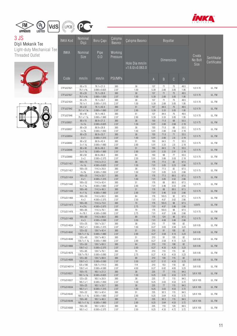
3 JSDişli Mekanik TeeLight-duty Mechanical Tee Threaded Outlet
İNKA KodNominal
ÖlçüBoru Çapı
Çalışma Basıncı
Çalışma Basıncı Boyutlar
Cıvata No Bolt
Size
SertifikalarCertificates
INKA
Code
Nominal Size
mm/in
Pipe O.D
mm/in
Working Pressure
PSI/MPa
Hole Dia mm/in +1.6.0/+0.063.0
Dimensions
A B C D
CTF3JS762165 x 15 76.1 x 21.3 300 38 137 71 75 49.5
1/2 X 70 UL, FM76.1 x ¾ 3.000 x 0.825 2.07 1.50 5.39 2.80 3.05 1.95
CTF3JS762765 x 20 76.1 x 26.9 300 38 137 71 75 49.5
1/2 X 70 UL, FM76.1 x ¾ 3.000 x 1.050 2.07 1.50 5.39 2.80 3.05 1.95
CTF3JS763465 x 25 76.1 x 33.7 300 38 137 71 75 49.5
1/2 X 70 UL, FM76.1 x 1 3.000 x 1.315 2.07 1.50 5.39 2.80 3.05 1.95
CTF3JS764265 x 32 76.1 x 42.4 300 51 137 84.5 75 49.5
1/2 X 70 UL, FM76.1 x 1 ¼ 3.000 x 1.660 2.07 2.00 5.39 3.33 3.05 1.95
CTF3JS764865 x 40 76.1 x 48.3 300 51 137 84.5 75 49.5
1/2 X 70 UL, FM76.1 x 1 ½ 3.000 x 1.900 2.07 2.00 5.39 3.33 3.05 1.95
CTF3JS892180 x 15 88.9 x 21.3 300 38 150 71.0 68 55.5
1/2 X 75 UL, FM3 x ½ 3.500 x 0.825 2.07 1.50 5.91 2.80 2.68 2.19
CTF3JS892780 x 20 88.9 x 26.9 300 38 150 71.0 68 55.5
1/2 X 75 UL, FM3 x ¾ 3.500 x 1.050 2.07 1.50 5.91 2.80 2.68 2.19
CTF3JS893480 x 25 88.9 x 33.7 300 38 150 71.0 71 55.5
1/2 X 75 UL, FM3 x 1 3.500 x 1.315 2.07 1.50 5.91 2.80 2.8 2.19
CTF3JS894280 x 32 88.9 x 42.4 300 51 150 84.5 71 55.5
1/2 X 75 UL, FM3 x 1 ¼ 3.500 x 1.660 2.07 2.00 5.91 3.33 2.8 2.19
CTF3JS894880 x 40 88.9 x 48.3 300 51 150 84.5 74 55.5
1/2 X 75 UL, FM3 x 1 ½ 3.500 x 1.900 2.07 2.00 5.91 3.33 2.91 2.19
CTF3JS896080 x 50 88.9 x 60.3 300 64 150 98 77 55.5
1/2 X 75 UL, FM3 x 2 3.500 x 2.375 2.07 2.50 5.91 3.86 3.03 2.19
CTF3JS11421100 x 15 114.3 x 21.3 300 38 178 77.5 82 67.5
1/2 X 75 UL, FM4 x ½ 4.500 x 0.825 2.07 1.50 7.01 3.05 3.23 2.66
CTF3JS11427100 x 20 114.3 x 26.9 300 38 178 77.5 82 67.5
1/2 X 75 UL, FM4 x ¾ 4.500 x 1.050 2.07 1.50 7.01 3.05 3.23 2.66
CTF3JS11434100 x 25 114.3 x 33.7 300 38 178 77.5 89.5 67.5
1/2 X 75 UL, FM4 x 1 4.500 x 1.315 2.07 1.50 7.01 3.05 3.52 2.66
CTF3JS11442100 x 32 114.3 x 42.4 300 51 178 88 89.5 67.5
1/2 X 75 UL, FM4 x 1 ¼ 4.500 x 1.660 2.07 2.00 7.01 3.46 3.53 2.66
CTF3JS11448100 x 40 114.3 x 48.3 300 51 178 88 89.5 67.5
1/2 X 75 UL, FM4 x 1 ½ 4.500 x 1.900 2.07 2.00 7.01 3.46 3.53 2.66
CTF3JS11460100 x 50 114.3 x 60.3 300 64 178 103.5 92 67.5
1/2 X 75 UL, FM4 x 2 4.500 x 2.375 2.07 2.50 7.01 4.07 3.62 2.66
CTF3JS11473100 x 65 114.3 x 73.0 300 70 178 103.5 98 67.5
1/2X75 UL, FM4 x 2½ 4.500 x 2.875 2.07 2.75 7.01 4.07 3.86 2.66
CTF3JS11476100 x 65 114.3 x 76.1 300 70 178 103.5 98 67.5
1/2 X 75 UL, FM4 x 76.1 4.500 x 3.000 2.07 2.75 7.01 4.07 3.86 2.66
CTF3JS11489100 x 80 114.3 x 88.9 300 89 178 124 98 67.5
1/2 X 75 UL, FM4 x 3 4.500 x 3.500 2.07 3.50 7.01 4.88 3.86 2.66
CTF3JS14034125 x 25 139.7 x 33.7 300 38 210 77 100 82
5/8 X 85 UL, FM139.7 x 1 5.500 x 1.315 2.07 1.50 8.27 3.03 3.94 3.23
CTF3JS14042125 x 32 139.7 x 42.4 300 51 210 91 105 82
5/8 X 85 UL, FM139.7 x 1 ¼ 5.500 x 1.660 2.07 2.00 8.27 3.58 4.13 3.23
CTF3JS14048125 x 40 139.7 x 48.3 300 51 210 91 105 82
5/8 X 85 UL, FM139.7 x 1 ½ 5.500 x 1.900 2.07 2.00 8.27 3.58 4.13 3.23
CTF3JS14060125 x 50 139.7 x 60.3 300 64 210 110 108 82
5/8 X 85 UL, FM139.7 x 2 5.500 x 2.375 2.07 2.50 8.27 4.33 4.25 3.23
CTF3JS14076125 x 65 139.7 x 76.1 300 70 210 110 115 82
5/8 X 85 UL, FM139.7 x 76.1 5.500 x 3.000 2.07 2.75 8.27 4.33 4.53 3.23
CTF3JS14089125 x 80 139.7 x 88.9 300 89 210 130 115 82
5/8 X 85 UL, FM139.7 x 3 5.500 x 3.500 2.07 3.50 8.27 5.12 4.53 3.23
CTF3JS140114125 x 100 139.7 x 114.3 300 114 210 153 118 82
5/8 X 85 UL, FM139.7 x 4 5.500 x 4.500 2.07 4.50 8.27 6.02 4.65 3.23
CTF3JS16521150 x 15 165.1 x 21.3 300 38 235 77 115 94.5
5/8 X 105 UL, FM165.1 x ½ 6.500 x 0.825 2.07 1.50 9.25 3.03 4.53 3.72
CTF3JS16527125 x 20 165.1 x 26.9 300 38 235 77 115 94.5
5/8 X 105 UL, FM165.1 x 1 6.500 x 1.050 2.07 1.50 9.25 3.03 4.53 3.72
CTF3JS16534150 x 25 165.1 x 33.7 300 38 235 77 115 94.5
5/8 X 105 UL, FM165.1 x 1 6.500 x 1.315 2.07 1.50 9.25 3.03 4.53 3.72
CTF3JS16542150 x 32 165.1 x 42.4 300 51 235 92.5 115 94.5
5/8 X 105 UL, FM165.1 x 1 ¼ 6.500 x 1.660 2.07 2.00 9.25 3.64 4.53 3.72
CTF3JS16548150 x 40 165.1 x 48.3 300 51 235 92.5 115 94.5
5/8 X 105 UL, FM165.1 x 1 ½ 6.500 x 1.900 2.07 2.00 9.25 3.64 4.53 3.72
CTF3JS16560150 x 50 165.1 x 60.3 300 64 235 110 120 94.5
5/8 X 105 UL, FM165.1 x 2 6.500 x 2.375 2.07 2.50 9.25 4.33 4.72 3.72

12
3 LU-Bolt Mekanik TeeU-Bolt Mechanical Tee
İNKA Kod
Nominal Ölçü
Boru Çapı
Çalışma Basıncı
Boyutlar
U Cıvata No U Bolt Size
SertifikalarCertificatesINKA
Code
Nominal Size
mm/in
Pipe O.D
mm/in
Working Pressure
PSI/MPa
Dimensions
A B C
CBF3L423432 x 25 30 300 54,4 88,9 57,2
3/8 x 73 UL, FM1 1/4 x 1 1,18 2,07 2,14 3,5 2,25
CBF3L482140 x 15 30 300 43 88,9 57,2
3/8 x 73 UL, FM1 1/2 x 1/2 1,18 2,07 1,69 3,5 2,25
CBF3L482740 x 20 30 300 51 88,9 57,2
3/8 x 73 UL, FM1 1/2 x 3/4 1,18 2,07 2,0 3,5 2,25
CBF3L483440 x 25 30 300 60,8 88,9 57,2
3/8 x 73 UL, FM1 1/2 x 1 1,18 2,07 2,39 3,5 2,25
CBF3L602150 x 15 30 300 63,3 95,3 57,2
3/8 x 90 UL, FM, VDS2 x 1/2 1,18 2,07 2,49 3,75 2,25
CBF3L732165 x 15 30 300 69,9 108 57,2
3/8 x 105 UL, FM2½ x 1/2 1,18 2,07 2,75 4,25 2.250
CBF3L732765 x 20 30 300 69,9 108 57,2
3/8 x 105 UL, FM2½ x 3/4 1,18 2,07 2,75 4,25 2.250
CBF3L733465 x 25 30 300 73,2 108 57,2
3/8 x 105 UL, FM2½ x 1 1,18 2,07 2,88 4,25 2,25
CBF3L602750 x 20 30 300 63,3 95,3 57,2
3/8 x 90 UL, FM, VDS2 x 3/4 1,18 2,07 2,49 3,75 2,25
CBF3L603450 x 25 30 300 66,6 95,3 57,2
3/8 x 90 UL, FM, VDS2 x 1 1,18 2,07 2,62 3,75 2,25
CBF3L762165 x 15 30 300 69,9 108 57,2
3/8 x 105 UL, FM, VDS76,1 x 1/2 1,18 2,07 2,75 4,25 2.250
CBF3L762765 x 20 30 300 69,9 108 57,2
3/8 x 105 UL, FM, VDS76,1 x 3/4 1,18 2,07 2,75 4,25 2.250
CBF3L763465 x 25 30 300 73,2 108 57,2
3/8 x 105 UL, FM, VDS76,1 x 1 1,18 2,07 2,88 4,25 2,25
3 JSDişli Mekanik TeeLight-duty Mechanical Tee Threaded Outlet
İNKA KodNominal
ÖlçüBoru Çapı
Çalışma Basıncı
Çalışma Basıncı Boyutlar
Cıvata No Bolt
Size
SertifikalarCertificates
INKA
Code
Nominal Size
mm/in
Pipe O.D
mm/in
Working Pressure
PSI/MPa
Hole Dia mm/in +1.6.0/+0.063.0
Dimensions
A B C D
CTF3JS16576150 x 65 165.1 X 76.1 300 70 235 110 125 94.5
5/8 x 105 UL, FM165,1 x 76,1 6.500 X 3.000 2,07 2.75 9.25 4.33 4.92 3.72
CTF3JS16589150 x 80 165.1 x 88.9 300 89 235 130 125 94.5
5/8 x 105 UL, FM165.1 x 3 6.500 x 3.500 2,07 3.5 9.25 5.12 4.92 3.72
CTF3JS165114150 x 100 165.1 x 114.3 300 114 240 155 130 94.5
5/8 x 105 UL, FM165.1 x 4 6.500 x 4.500 2,07 4.5 9.45 6.1 5.12 3.72
CTF3JS16834150 x 25 168.3 x 33.7 300 38 240 77 115 96.5
5/8 x 105 UL, FM6 x 1 6.500 x 1.315 2,07 1.50 9.45 3.03 4.53 3.80
CTF3JS16842150 x 32 168.3 x 42.4 300 51 240 92.5 115 96.5
5/8 x 105 UL, FM6 x 1¼ 6.500 x 1.660 2,07 2.00 9.45 3.64 4.53 3.80
CTF3JS16848150 x 40 168.3 x 48.3 300 51 240 92.5 115 96.5
5/8 x 105 UL, FM6 x 1½ 6.500 x 1.900 2,07 2.00 9.45 3.64 4.53 3.80
CTF3JS16860150 x 50 168.3 x 60.3 300 64 240 110 121 96.5
5/8 x 105 UL, FM6 x 2 6.625 x 2.375 2,07 2.5 9.45 4.33 4.76 3.80
CTF3JS21960200 x 50 219.1 x 60.3 300 64 300 117 149 123
5/8 x 105 UL, FM8 x 2 8.625 x 2.375 2,07 2.5 11.81 4.61 5.87 4.84
CTF3JS21976200 x 65 219.1 x 76.1 300 70 300 117 155 123
5/8 x 105 UL, FM8 x 76.1 8.625 x 3.000 2,07 2.75 11.81 4.61 6.10 4.84
CTF3JS21989200 x 80 219.1 x 88.9 300 89 300 133.5 155 123
5/8 x 105 UL, FM8 x 3 8.625 x 3.500 2,07 3.50 11.81 5.25 6.10 4.84
CTF3JS219114200 x 100 219.1 x 114.3 300 114 300 164 160 123
5/8 x 105 UL, FM8 x 4 8.625 x 4.500 2,07 4.50 11.81 6.45 6.30 4.84
13
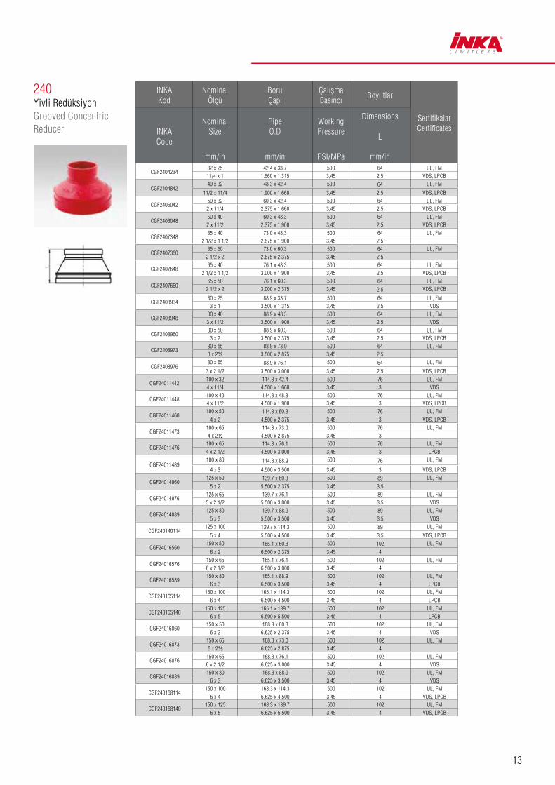
240Yivli RedüksiyonGrooved Concentric Reducer
İNKA Kod
Nominal Ölçü
Boru Çapı
ÇalışmaBasıncı
Boyutlar
SertifikalarCertificatesINKA
Code
Nominal Size
mm/in
Pipe O.D
mm/in
Working Pressure
PSI/MPa
Dimensions
L
mm/in
CGF240423432 x 25 42.4 x 33.7 500 64 UL, FM11/4 x 1 1.660 x 1.315 3,45 2,5 VDS, LPCB
CGF240484240 x 32 48.3 x 42.4 500 64 UL, FM
11/2 x 11/4 1.900 x 1.660 3,45 2,5 VDS, LPCB
CGF240604250 x 32 60.3 x 42.4 500 64 UL, FM2 x 11/4 2.375 x 1.660 3,45 2,5 VDS, LPCB
CGF240604850 x 40 60.3 x 48.3 500 64 UL, FM2 x 11/2 2.375 x 1.900 3,45 2,5 VDS, LPCB
CGF240734865 x 40 73,0 x 48,3 500 64 UL, FM
2 1/2 x 1 1/2 2.875 x 1.900 3,45 2,5
CGF240736065 x 50 73,0 x 60,3 500 64 UL, FM
2 1/2 x 2 2.875 x 2.375 3,45 2,5
CGF240764865 x 40 76.1 x 48.3 500 64 UL, FM
2 1/2 x 1 1/2 3.000 x 1.900 3,45 2,5 VDS, LPCB
CGF240766065 x 50 76.1 x 60.3 500 64 UL, FM
2 1/2 x 2 3.000 x 2.375 3,45 2,5 VDS, LPCB
CGF240893480 x 25 88.9 x 33.7 500 64 UL, FM
3 x 1 3.500 x 1.315 3,45 2,5 VDS
CGF240894880 x 40 88.9 x 48.3 500 64 UL, FM3 x 11/2 3.500 x 1.900 3,45 2,5 VDS
CGF240896080 x 50 88.9 x 60.3 500 64 UL, FM
3 x 2 3.500 x 2.375 3,45 2,5 VDS, LPCB
CGF240897380 x 65 88.9 x 73.0 500 64 UL, FM3 x 2½ 3.500 x 2.875 3,45 2,5
CGF240897680 x 65 88.9 x 76.1 500 64 UL, FM
3 x 2 1/2 3.500 x 3.000 3,45 2,5 VDS, LPCB
CGF24011442100 x 32 114.3 x 42.4 500 76 UL, FM4 x 11/4 4.500 x 1.660 3,45 3 VDS
CGF24011448100 x 40 114.3 x 48.3 500 76 UL, FM4 x 11/2 4.500 x 1.900 3,45 3 VDS, LPCB
CGF24011460100 x 50 114.3 x 60.3 500 76 UL, FM
4 x 2 4.500 x 2.375 3,45 3 VDS, LPCB
CGF24011473100 x 65 114.3 x 73.0 500 76 UL, FM4 x 2½ 4.500 x 2.875 3,45 3
CGF24011476100 x 65 114.3 x 76.1 500 76 UL, FM4 x 2 1/2 4.500 x 3.000 3,45 3 LPCB
CGF24011489100 x 80 114.3 x 88.9 500 76 UL, FM
4 x 3 4.500 x 3.500 3,45 3 VDS, LPCB
CGF24014060125 x 50 139.7 x 60.3 500 89 UL, FM
5 x 2 5.500 x 2.375 3,45 3,5
CGF24014076125 x 65 139.7 x 76.1 500 89 UL, FM5 x 2 1/2 5.500 x 3.000 3,45 3,5 VDS
CGF24014089125 x 80 139.7 x 88.9 500 89 UL, FM
5 x 3 5.500 x 3.500 3,45 3,5 VDS
CGF240140114125 x 100 139.7 x 114.3 500 89 UL, FM
5 x 4 5.500 x 4.500 3,45 3,5 VDS, LPCB
CGF24016560150 x 50 165.1 x 60.3 500 102 UL, FM
6 x 2 6.500 x 2.375 3,45 4
CGF24016576150 x 65 165.1 x 76.1 500 102 UL, FM6 x 2 1/2 6.500 x 3.000 3,45 4
CGF24016589150 x 80 165.1 x 88.9 500 102 UL, FM
6 x 3 6.500 x 3.500 3,45 4 LPCB
CGF240165114150 x 100 165.1 x 114.3 500 102 UL, FM
6 x 4 6.500 x 4.500 3,45 4 LPCB
CGF240165140150 x 125 165.1 x 139.7 500 102 UL, FM
6 x 5 6.500 x 5.500 3,45 4 LPCB
CGF24016860150 x 50 168.3 x 60.3 500 102 UL, FM
6 x 2 6.625 x 2.375 3,45 4 VDS
CGF24016873150 x 65 168.3 x 73.0 500 102 UL, FM6 x 2½ 6.625 x 2.875 3,45 4
CGF24016876150 x 65 168.3 x 76.1 500 102 UL, FM6 x 2 1/2 6.625 x 3.000 3,45 4 VDS
CGF24016889150 x 80 168.3 x 88.9 500 102 UL, FM
6 x 3 6.625 x 3.500 3,45 4 VDS
CGF240168114150 x 100 168.3 x 114.3 500 102 UL, FM
6 x 4 6.625 x 4.500 3,45 4 VDS, LPCB
CGF240168140150 x 125 168.3 x 139.7 500 102 UL, FM
6 x 5 6.625 x 5.500 3,45 4 VDS, LPCB

14
CGF24021989200 x 80 219.1 x 88.9 500 127 UL, FM
8 x 3 8.625 x 3.500 3,45 5 VDS, LPCB
CGF240219114200 x 100 219.1 x 114.3 500 127 UL, FM
8 x 4 8.625 x 4.500 3,45 5 LPCB
CGF240219140200 x 125 219.1 x 139.7 500 127 UL, FM
8 x 5 8.625 x 5.500 3,45 5 VDS, LPCB
CGF240219165200 x 150 219.1 x 165.1 300 127 UL, FM
8 x 6 8.625 x 6.500 2,07 5
CGF240219168200 x 150 219.1 x 168.3 500 127 UL, FM
8 x 6 8.625 x 6.625 3,45 5 VDS, LPCB
CGF240273165250 x 150 273.0 x 165.1 300 152 UL, FM
10 x 6 10.750 x 6.500 2,07 6
CGF240273168250 x 150 273.0 x 168.3 300 152 UL, FM
10 x 6 10.750 x 6.625 2,07 6 VDS
CGF240273219250 x 200 273.0 x 219.1 300 152 UL, FM
10 x 8 10.750 x 8.625 2,07 6 VDS
CGF240324219300 x 200 323.9 x 219.1 300 178 UL, FM
12 x 8 12.750 x 8.625 2,07 7 VDS
CGF240324273300 x 250 323.9 x 273.0 300 178 UL, FM
12 x 10 12.750 x 10.750 2,07 7 VDS
240Yivli RedüksiyonGrooved Concentric Reducer
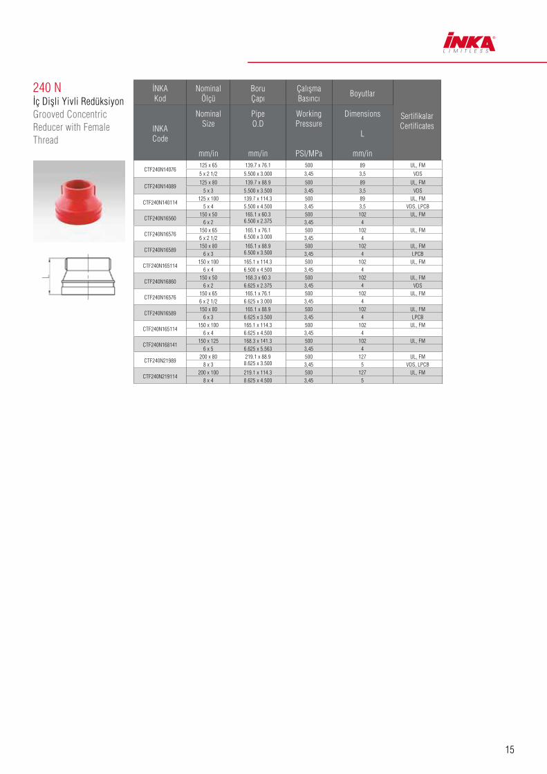
240 Nİç Dişli Yivli RedüksiyonGrooved Concentric Reducer with Female Thread
İNKA Kod
Nominal Ölçü
Boru Çapı
ÇalışmaBasıncı
Boyutlar
SertifikalarCertificatesINKA
Code
Nominal Size
mm/in
Pipe O.D
mm/in
Working Pressure
PSI/MPa
Dimensions
L
mm/in
İNKA Kod
Nominal Ölçü
Boru Çapı
ÇalışmaBasıncı
Boyutlar
SertifikalarCertificatesINKA
Code
Nominal Size
mm/in
Pipe O.D
mm/in
Working Pressure
PSI/MPa
Dimensions
L
mm/in
CTF240N604250 x 32 60.3 x 42.4 500 64 UL, FM2 x 11/4 2.375 x 1.660 3,45 2,5 VDS, LPCB
CTF240N604850 x 40 60.3 x 48.3 500 64 UL, FM2 x 11/2 2.375 x 1.900 3,45 2,5 VDS, LPCB
CTF240N734865 x 40 73,0 x 48,3 500 64 UL, FM
2 1/2 x 1 1/2 2.875 x 1.900 3,45 2,5
CTF240N736065 x 50 73,0 x 60,3 500 64 UL, FM
2 1/2 x 2 2.875 x 2.375 3,45 2,5
CTF240N764865 x 40 76.1 x 48.3 500 64 FM
2 1/2 x 1 1/2 3.000 x 1.900 3,45 2,5 VDS, LPCB
CTF240N766065 x 50 76.1 x 60.3 500 64 UL, FM
2 1/ 2x 2 3.000 x 2.375 3,45 2,5 VDS, LPCB
CTF240N893480 x 25 88.9 x 33.7 500 64 UL, FM
3 x 1 3.500 x 1.315 3,45 2,5 VDS
CTF240N894880 x 40 88.9 x 48.3 500 64 UL, FM
3 x 11/2 3.500 x 1.900 3,45 2,5 VDS
CTF240N896080 x 50 88.9 x 60.3 500 64 UL, FM
3 x 2 3.500 x 2.375 3,45 2,5 VDS
CTF240N897380 x 65 88.9 x 73.0 500 64 UL, FM
3 x 2½ 3.500 x 2.875 3,45 2,5
CTF240N897680 x 65 88.9 x 76.1 500 64 UL, FM
3 x 2 1/2 3.500 x 3.000 3,45 2,5 VDS, LPCB
CTF240N11442100 x 32 114.3 x 42.4 500 76 UL, FM
4 x 11/4 4.500 x 1.660 3,45 3 VDS
CTF240N11448100 x 40 114.3 x 48.3 500 76 UL, FM
4 x 11/2 4.500 x 1.900 3,45 3 VDS, LPCB
CTF240N11460100 x 50 114.3 x 60.3 500 76 UL, FM
4 x 2 4.500 x 2.375 3,45 3 VDS, LPCB
CTF240N11473100 x 65 114.3 x 73.0 500 76 UL, FM
4 x 2½ 4.500 x 2.875 3,45 3
CTF240N11476100 x 65 114.3 x 76.1 500 76 UL, FM
4 x 2 1/2 4.500 x 3.000 3,45 3 VDS, LPCB
CTF240N11489100 x 80 114.3 x 88.9 500 76 UL, FM
4 x 3 4.500 x 3.500 3,45 3 VDS, LPCB
CTF240N14060125 x 50 139.7 x 60.3 500 89 UL, FM
5 x 2 5.500 x 2.375 3,45 3,5 VDS
15
240 Nİç Dişli Yivli RedüksiyonGrooved Concentric Reducer with Female Thread
İNKA Kod
Nominal Ölçü
Boru Çapı
ÇalışmaBasıncı
Boyutlar
SertifikalarCertificatesINKA
Code
Nominal Size
mm/in
Pipe O.D
mm/in
Working Pressure
PSI/MPa
Dimensions
L
mm/in
CTF240N14076125 x 65 139.7 x 76.1 500 89 UL, FM
5 x 2 1/2 5.500 x 3.000 3,45 3,5 VDS
CTF240N14089125 x 80 139.7 x 88.9 500 89 UL, FM
5 x 3 5.500 x 3.500 3,45 3,5 VDS
CTF240N140114125 x 100 139.7 x 114.3 500 89 UL, FM
5 x 4 5.500 x 4.500 3,45 3,5 VDS, LPCB
CTF240N16560150 x 50 165.1 x 60.3
6.500 x 2.375500 102 UL, FM
6 x 2 3,45 4
CTF240N16576150 x 65 165.1 x 76.1
6.500 x 3.000500 102 UL, FM
6 x 2 1/2 3,45 4
CTF240N16589150 x 80 165.1 x 88.9
6.500 x 3.500500 102 UL, FM
6 x 3 3,45 4 LPCB
CTF240N165114150 x 100 165.1 x 114.3 500 102 UL, FM
6 x 4 6.500 x 4.500 3,45 4
CTF240N16860150 x 50 168.3 x 60.3 500 102 UL, FM
6 x 2 6.625 x 2.375 3,45 4 VDS
CTF240N16576150 x 65 165.1 x 76.1 500 102 UL, FM6 x 2 1/2 6.625 x 3.000 3,45 4
CTF240N16589150 x 80 165.1 x 88.9 500 102 UL, FM
6 x 3 6.625 x 3.500 3,45 4 LPCB
CTF240N165114150 x 100 165.1 x 114.3 500 102 UL, FM
6 x 4 6.625 x 4.500 3,45 4
CTF240N168141150 x 125 168.3 x 141.3 500 102 UL, FM
6 x 5 6.625 x 5.563 3,45 4
CTF240N21989200 x 80 219.1 x 88.9
8.625 x 3.500500 127 UL, FM
8 x 3 3,45 5 VDS, LPCB
CTF240N219114200 x 100 219.1 x 114.3 500 127 UL, FM
8 x 4 8.625 x 4.500 3,45 5
16
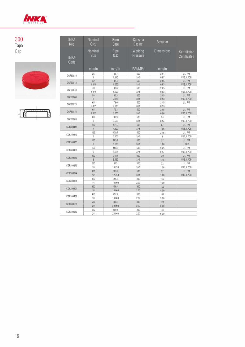
300TapaCap
İNKA Kod
Nominal Ölçü
Boru Çapı
ÇalışmaBasıncı
Boyutlar
SertifikalarCertificatesINKA
Code
Nominal Size
mm/in
Pipe O.D
mm/in
Working Pressure
PSI/MPa
Dimensions
L
mm/in
CGF3003425 33,7 500 22,1 UL, FM1 1.315 3,45 0,87 VDS, LPCB
CGF3004232 42,4 500 23,5 UL, FM
1 1/4 1.660 3,45 0,93 VDS, LPCB
CGF3004840 48,3 500 23,5 UL, FM
1 1/2 1.900 3,45 0,93 VDS, LPCB
CGF3006050 60,3 500 23,5 UL, FM2 2.375 3,45 0,93 VDS, LPCB
CGF3007365 73.0 500 23,5 UL, FM
2 1/2 2.875 3,45 0,93
CGF3007665 76,1 500 24,5 UL, FM
2 1/2 3.000 3,45 0,96 VDS, LPCB
CGF3008980 88,9 500 24 UL, FM
3 3.500 3,45 0,94 VDS, LPCB
CGF300114100 114,3 500 27 UL, FM
4 4.500 3,45 1,06 VDS, LPCB
CGF300140125 139,7 500 25,5 UL, FM
5 5.500 3,45 1 VDS, LPCB
CGF300165150 165,1 500 27 UL, FM
6 6.500 3,45 1,06 LPCB
CGF300168150 168,3 500 24,5 UL, FM
6 6.625 3,45 0,97 VDS, LPCB
CGF300219200 219,1 500 30 UL, FM
8 8.625 3,45 1,18 VDS, LPCB
CGF300273250 273 500 32 UL, FM
10 10.750 3,45 1,26 VDS, LPCB
CGF300324300 323,9 500 32 UL, FM
12 12.750 3,45 1,26 VDS, LPCB
CGF300356350 355.6 300 102
14 14.000 2.07 4.00
CGF300407400 406.4 300 102
16 16.000 2.07 4.00
CGF300458450 457.2 300 127
18 18.000 2.07 5.00
CGF300508500 508.0 300 152
20 20.000 2.07 6.00
CGF300610600 609.6 300 152
24 24.000 2.07 6.00

17
321-PN16Yivli FlanflGrooved Flange
İNKA Kod
Nominal Ölçü
Boru Çapı
Çalışma Basıncı
Boyutlar Somun/Civata
SertifikalarCertificatesINKA
Code
Nominal Size
mm/in
Pipe O.D
mm/in
Working Pressure
PSI/MPa
Dimensions Bolt/Nut
A mm/in
Bmm/in
Cmm/in
Dmm/in
Emm/in
No.-Boyut mmNo.-Size mm
CGF3214840 48,3 225 195 18.5 150 110 45,4
2 - M10 x 50 4 - M16UL, FM
1 1/2 1.900 1.6 7,68 0,73 5,9 4,33 1,78 VDS
CGF3216050 60,3 225 220 18.5 165 125 57,5
2 - M10 x 50 4 - M16UL, FM
2 2.375 1.6 8,66 0,73 6,5 4,92 2,26 VDS
CGF3217665 76,1 225 235 18.5 185 145 72,7
2 - M10 x 50 4 - M16UL, FM
76,1 3.000 1.6 9,25 0,73 7,28 5,71 2,86 VDS
CGF3218980 88,9 225 255 18.5 195 160 85,5
2 - M10 x 50 8 - M16UL, FM
3 3.500 1.6 10,04 0,73 7,68 6,3 3,37 VDS
CGF321114100 114,3 225 279 18.5 224 180 110,5
2 - M10 x 50 8 - M16UL, FM
4 4.500 1.6 10,98 0,73 8,82 7,09 4,35 VDS
CGF321140125 139,7 225 320 23 250 210 135,5
2 - M12 x 65 8 - M16UL, FM
5 5.500 1.6 12,6 0,91 9,84 8,27 5,33
CGF321165150 165,1 225 346 21,5 280 240 160,8
2 - M12 x 65 8 - M20UL, FM
6 6.500 1.6 13,62 0,85 11 9,45 6,33
CGF321168150 168.3 225 346 24 280 240 164.3
2 - M12 x 65 8 - M20UL, FM
6 6.625 1.6 13,62 0.94 11 9,45 6,47
CGF321219200 219,1 225 414,3 30 340 295 214,9
2 - 3/8 x 70 12 - M20UL, FM
8 8.625 1.6 16,31 1,18 13,39 11,61 8,46 VDS
CGF321273250 273 225 480 25,5 405 355 268,9
2 - 3/8 x 70 12 - M24UL, FM
10 10.750 1.6 18,9 1 15,94 13,98 10,59 VDS
CGF321324300 323,9 225 530,5 25,5 460 410 318,9
2 - 3/8 x 70 12 - M24UL, FM
12 12.750 1.6 20,88 1 18,11 16,14 12,56
CGF321356350 355.6 225 580 30 520 470 350.6
------- 16 - M2414 12.750 1.6 22.83 1.18 20.47 18.50 13.80
CGF321407400 406.4 225 630 32 580 525 401.5
------- 16 - M2716 16.000 1.6 24.80 1.26 22.83 20.67 15.81
CGF321457450 457.2 225 693 36 640 585 452.2
------- 20 - M2718 18.000 1.6 27.28 1.42 25.20 23.03 17.80
CGF321508500 508.0 225 770 36 715 650 503
------- 20 - M3020 20.000 1.6 30.31 1.42 28.15 25.59 19.80
CGF321610600 609.6 225 895 40 840 770 601.6
------- 20 - M3324 24.000 1.6 35.24 1.57 33.07 30.31 23.69

18
180R
240N
Mavi Blue
Portakal RengiOrange
90R
181
240W GalvanizliGalvanized
Beyaz White
110
230
300PX
105
3J
131R
230N
321G
Yivli Redüksiyon İstavroz
Reducing Cross
İçeriden Diflli Redüksiyon
Grooved Concentric Reducer With
Female Thread
90° Redüksiyon Dirsek
90° Reducing Elbow
Yivli Redüksiyon İstavroz
Reducing Cross
D›flar›dan Diflli Redüksiyon
Grooved Concentric Reducer With
Male Thread
22.5° Dirsek
22.5° Elbow
Yivli Eksantrik Redüksiyon
Grooved Eccentric Reducer
Tapa
Cap
11.25° Dirsek
11.25° Elbow
Diflli Mekanik Tee
Mechanical Tee Threaded Outlet
Yivli Redüksiyon Tee
Reducing Tee
İç Diflli Eksantrik Redüksiyon
Grooved Eccentric Reducer With
Female Thread
Adaptör Flanfl
Adaptor Flange
Not: Yukarıda belirtilen ürün grupları sipariş e göre getirilmektedir.P.S.: The above mentioned products will be supplied upon request.
Yivli Bağlantı Elemanları Ductile Iron Grooved Fittings

19
Sızdırmaz Conta Karakteristikleri (Gasket Data)
Sızdırmaz Conta
Gasket
Sıcaklık Aralığı
Temperature Range
Genel Kullanım Tavsiyeleri
General Service Recommendations
Renkİşareti
Color Mark
E -34 ~ +110°C(-30 ~ +230°F)
Belirtilen sıcaklık aralığında ve buna ek olarak çeşitli seyreltik asitler, yağsız hava ve pek çok kimyasal ile kullanımı tavsiye edilir. ANSI/NSF 61 veya soğuk + 86°F (+30°C) ve sıcak +180°F (+82°C) içilebilir su ile uyumlu UL sınıflandırılmıştır. Petrol işlerinde kullanımı tavsiye edilmez.
Recommended for hot water service within the specified temperature range plus a variety of dilute acids, oil-free air and many chemicalservices. UL classifi ed in ccordance with ANSI/ NSF 61or cold+86°F (+30°C) and hot +180°F (+82°C) potable water service. Not recommended for petroleum service.
Yeşil ÇizgiGreen Strip
D -29 ~+82°C(-20 ~ +180°F)
Belirtilen sıcaklık aralığında petrol ürünleri, yağ buharlı hava, bitkisel ve mineral yağlar ile kullanımı tavsiye edilir. Sıcak su ile kullanımı tavsiye edilmez.
(Recommended for petroleum products. Air with oil vapors, vegetable and mineral oils within thespecified temperature range. Not recommended for hot water services.)
Turuncu ÇizgiOrange Strip
S -40 ~ +177°C(-40 ~ +350°F)
Yüksek sıcaklıklı kuru hava ve bazı yüksek sıcaklıklı kimyasal ürünlerle kullanımı tavsiye edilir.
(Recommended for high temperature dry air and some high temperature chemical products.)
BeyazWhite

20
Boru Delik Ölçüleri Hole Diameter of pipe
AnahatÖlçüsü
Run Nominal Size
mmm/in
NominalÖlçü
OutletNominal Size
mm/in
Delik Çapı
Hole Dia.+3.2,0+0.13,0
mm/in
AnahatÖlçüsü
Run NominalSize
mm/in
Nominal Ölçü
OutletNominal Size
mm/in
Delik Çapı
Hle Dia.+3.2,0+0.13,0
mm/in
AnahatÖlçüsü
Run NominalSize
mm/in
NominalÖlçü
OutletNominal Size
mm/in
Delik Çapı
Hole Dia.+3.2,0+0.13,0
mm/in
502”/60,3
151/2
381,50A89
100108,0
4”/114,3
151/2
381,50A89
150159,0165,1
6”/168,3
151/2
381,50A89
203/4
203/4
203/4
251
251
251
321½ 45
1,75A102
321 1/4 51
2,00A102
321 1/4 51
2,00A10240
1½401½
401½
652½/73.0
76,1
151/2
381,50A89
502
642,50A114
502
642,50A114
203/4
652½/76,1
702,75A120
652½/76.1
702,75A120
251
803
893,50A140
803
893,50A140
321 1/4 51
2,00A102
125133,0139,7
5”/141,3
151/2
381,50A89
100108,0/4
1144,50A165
401½
203/4
2008”/219,1
25010”/273,0
251
381,50A89
803”/88,9
151/2
381,50A89
251
321 1/4 51
2,00A10220
3/432
1 1/4 512,00A102
401½
251
401½
502
642,50A114
321 1/4 51
2,00A102
502
642,50A114
65
2½/76,1
702,75A120
401½
652½/76,1
642,50A120
803
893,50A140
502
642,50A114
803
893,50A140
100108,0/4
1144,50A165
Delik çevresinden 16 mm sonrasına kadar boru yüzeyi temiz ve pürüzsüz olmalıdır.The outside surface of the pipe within 16 mm from the hole must be clean and smooth.
21
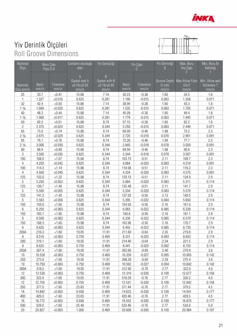
Yiv Derinlik Ölçüleri Roll Groove Dimensions
Nominal Ölçü
Nominal Size mm/in
Boru ÇapıPipe O.D
Contanın oturduğu alan
AGasket seat A±0.76/±0.03
mm/in
Yiv Geniflliği
BGasket with B±0.76/±0.03
mm/in
Yiv ÇapıC
Yiv Derinliği D
Groove Depth D (ref) mm/in
Max. Boru Dıfl Çapı
F
Max Allow Flare Dia F mm/in
Min. Boru Et Kalınlığı
T
Min. Allow wall thickness T
mm/inBasic mm/in
Tolerence mm/in
Basic mm/in
Tolerencemm/in
25 33.7 +0.41 15.88 7.14 30.23 -0.38 1.60 34.5 1.81 1.327 +0.016 0.625 0.281 1.190 -0.015 0.063 1.358 0.071
32 42.4 +0.50 15.88 7.14 38.99 -0.38 1.60 43.3 1.81 ¼ 1.669 +0.020 0.625 0.281 1.535 -0.015 0.063 1.705 0.07140 48.3 +0.44 15.88 7.14 45.09 -0.38 1.60 49.4 1.8
1 ½ 1.900 +0.017 0.625 0.281 1.779 -0.015 0.063 1,945 0.07150 60.3 +0.61 15.88 8.74 57.15 -0.38 1.60 62.2 1.82 2.375 +0.024 0.625 0.344 2.250 -0.015 0.063 2.449 0.071
65 73.0 +0.74 15.88 8.74 69.09 -0.46 1.98 75.2 2.32 ½ 2.875 +0.029 0.625 0.344 2.720 -0.018 0.078 2.961 0.09165 76.1 +0.76 15.88 8.74 72.26 -0.46 1.99 77.7 2.3
2 ½ 3.000 +0.030 0.625 0.344 2.845 -0.018 0.078 3.059 0.09180 88.9 +0.89 15.88 8.74 84.94 -0.46 1.98 90.6 2.33 3.500 +0.035 0.625 0.344 3.344 -0.018 0.078 3.567 0.091
100 108.0 +1.07 15.88 8.74 103.73 -0.51 2.11 109.7 2.34 4.250 +0.042 0.625 0.344 4.084 -0.020 0.083 4.319 0.091
100 114.3 +1.14 15.88 8.74 110.08 -0.51 2.11 116.2 2.34 4.500 +0.045 0.625 0.344 4.334 -0.020 0.083 4.575 0.091
125 133.0 +1.32 15.88 8.74 129.13 -0.51 2.11 134.9 2.95 5.250 +0.052 0.625 0.344 5.084 -0.020 0.083 5.311 0.114
125 139.7 +1.40 15.88 8.74 135.48 -0.51 2.11 141.7 2.95 5.500 +0.055 0.625 0.344 5.334 -0.020 0.083 5.579 0.114
125 141.3 +1.42 15.88 8.74 137.03 -0.56 2.13 143.5 2.95 5.563 +0.056 0.625 0.344 5.395 -0.022 0.084 5.650 0.114
150 159.0 +1.60 15.88 8.74 154.50 -0.56 2.16 161.0 2.96 6.250 +0.063 0.625 0.344 6.083 -0.022 0.085 6.339 0.114
150 165.1 +1.60 15.88 8.74 160.8 -0.56 2.16 167.1 2.96 6.500 +0.063 0.625 0.344 6.330 -0.022 0.085 6.579 0.114
150 168.3 +1.60 15.88 8.74 163.96 -0.56 2.16 170.7 2.96 6.625 +0.063 0.625 0.344 6.455 -0.022 0.085 6.720 0.114
200A 216.3 +1.60 19.05 11.91 211.60 -0.64 2.35 219.8 2.98 8.516 +0.063 0.750 0.469 8.331 -0.025 0.093 8.653 0.114
200 219.1 +1.60 19.05 11.91 214.40 -0.64 2.34 221.5 2.98 8.625 +0.063 0.750 0.469 8.441 -0.025 0.092 8.720 0.114
250A 267.4 +1.60 19.05 11.91 262.60 -0.69 2.40 270.9 3.610 10.528 +0.063 0.750 0.469 10.339 -0.027 0.095 10.665 0.142
250 273.0 +1.60 19.05 11.91 268.28 -0.69 2.39 275.4 3.610 10.750 +0.063 0.750 0.469 10.562 -0.027 0.094 10.842 0.142
300A 318.5 +1.60 19.05 11.91 312.90 -0.76 2.77 322.0 4.012 12.539 +0.063 0.750 0.469 12.319 -0.030 0.109 12.677 0.158
300 323.9 +1.60 19.05 11.91 318.29 -0.76 2.77 326.2 4.012 12.750 +0.063 0.750 0.469 12.531 -0.030 0.109 12.842 0.158
350 377.0 +1.60 23.83 11.91 371.44 -0.76 2.77 379.5 4.514 14.842 +0.063 0.938 0.469 14.623 -0.030 0.109 14.941 0.177
400 426.0 +1.60 23.83 11.91 420.46 -0.76 2.77 428.5 4.516 16.772 +0.063 0.938 0.469 16.553 -0.030 0.109 16.870 0.177
500 529.0 +1.60 25.40 11.91 523.46 -0.76 2.77 533.0 5.020 20.827 +0.063 1.000 0.469 20.608 -0.030 0.109 20.984 0.197
22
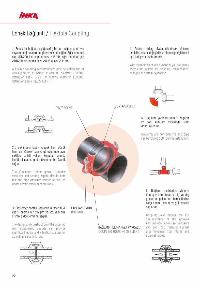
Esnek Bağlantı / Flexible Coupling
1. Esnek bir bağlantı aşağıdaki gibi boru sapmalarına ve/veya montaj hatalarının giderilmesini sağlar. Eğer nominal çap <DN200 ise, sapma açısı ≥1° dir, eğer nominal çap ≥DN200 ise sapma açısı ≥0.5° ancak < 1°dir.
A flexible coupling accommodates pipe deflection and or non-alignment as below: If nominal diameter <DN200, deflection angle is.≥1°; If nominal diameter ≥DN200, deflection angle is≥0.5°but < 1°.
2.C şeklindeki lastik kauçuk hem düşük hem de yüksek basınç görevlerinde aynı şekilde belirli vakum koşulları altında kendini kapatma gibi mükemmel bir özellik sağlar.
The C-shaped rubber gasket provides excellent self-sealing capabilities in both low and high pressure service as well as under certain vacuum conditions.
3. Elastomer contalı Bağlantının tasarım ve yapısı önemli bir titreşim ve ses yanı sıra sismik şiddet emilimi sağlar.
The design and construction of the coupling with elastomeric gaskets can provide significant noise and vibration absorption as well as seismic stress.
BAĞLANTI MUHAFAZA PARÇASI/COUPLING HOUSING SEGMENT
CIVATA/SOMUN BOLT/NUT
YİV/GROOVE CONTA/GASKET
4. Sadece birkaç civata çıkartarak sisteme temizlik, bakım, değişiklik ve sistem genişletmesi için kolayca erişebilirsiniz.
With the removal of just a few bolts you can easily access the system for cleaning, maintenance, changes or system expansion.
5. Bağlantı yönlendirilebilir değildir ve boru kurulum esnasında 360° döndürülebilir.
Coupling are non-directive and pipe can be rotated 360° during installation.
6. Bağlantı anahtarları yivlerin tüm çevresini tutar ve iç ve dış güçlerden gelen boru hareketlerine karşı önemli basınç ve yük baskısı sağlarlar.
Coupling keys engage the full circumference of the grooves and provide significant pressure and end load restraint against pipe movement from internal and external forces.
23
Rijit Bağlantı / Rigid Coupling
Mekanik Tee / Mechanical Tee
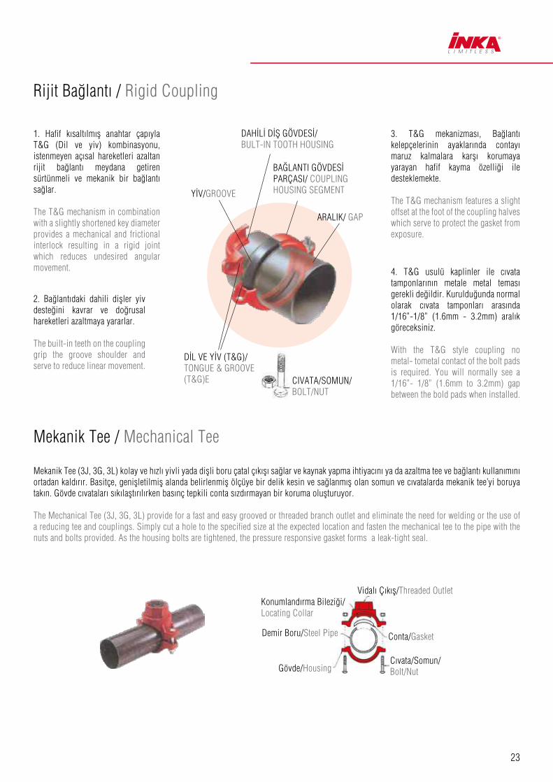
1. Hafif kısaltılmış anahtar çapıyla T&G (Dil ve yiv) kombinasyonu, istenmeyen açısal hareketleri azaltan rijit bağlantı meydana getiren sürtünmeli ve mekanik bir bağlantı sağlar.
The T&G mechanism in combination with a slightly shortened key diameter provides a mechanical and frictional interlock resulting in a rigid joint which reduces undesired angular movement.
3. T&G mekanizması, Bağlantı kelepçelerinin ayaklarında contayı maruz kalmalara karşı korumaya yarayan hafif kayma özelliği ile desteklemekte.
The T&G mechanism features a slight offset at the foot of the coupling halves which serve to protect the gasket from exposure.
4. T&G usulü kaplinler ile cıvata tamponlarının metale metal teması gerekli değildir. Kurulduğunda normal olarak cıvata tamponları arasında 1/16”-1/8” (1.6mm - 3.2mm) aralık göreceksiniz.
With the T&G style coupling no metal- tometal contact of the bolt pads is required. You will normally see a 1/16”- 1/8” (1.6mm to 3.2mm) gap between the bold pads when installed.
2. Bağlantıdaki dahili dişler yiv desteğini kavrar ve doğrusal hareketleri azaltmaya yararlar.
The built-in teeth on the coupling grip the groove shoulder and serve to reduce linear movement.
Mekanik Tee (3J, 3G, 3L) kolay ve hızlı yivli yada dişli boru çatal çıkışı sağlar ve kaynak yapma ihtiyacını ya da azaltma tee ve bağlantı kullanımını ortadan kaldırır. Basitçe, genişletilmiş alanda belirlenmiş ölçüye bir delik kesin ve sağlanmış olan somun ve cıvatalarda mekanik tee’yi boruya takın. Gövde cıvataları sıkılaştırılırken basınç tepkili conta sızdırmayan bir koruma oluşturuyor.
The Mechanical Tee (3J, 3G, 3L) provide for a fast and easy grooved or threaded branch outlet and eliminate the need for welding or the use of a reducing tee and couplings. Simply cut a hole to the specified size at the expected location and fasten the mechanical tee to the pipe with the nuts and bolts provided. As the housing bolts are tightened, the pressure responsive gasket forms a leak-tight seal.
YİV/GROOVE
DİL VE YİV (T&G)/ TONGUE & GROOVE (T&G)E
Konumland›rma Bileziği/Locating Collar
Vidalı Çıkış/Threaded Outlet
Conta/Gasket
Cıvata/Somun/Bolt/Nut
Demir Boru/Steel Pipe
Gövde/Housing
CIVATA/SOMUN/ BOLT/NUT
DAHİLİ DİŞ GÖVDESİ/ BULT-IN TOOTH HOUSING
BA⁄LANTI GÖVDESİ PARÇASI/ COUPLING HOUSING SEGMENT
ARALIK/ GAP

24
Çelik Borulardaki İNKA Kaplinlerin Basınç Sınıfları ve Taşıma Yükleri Pressure Ratings and End Loads for INKA Couplings on Steel Pipe
1G Rigid 1GS L/Duty Rigid 1NR Reducing
Nominal Ölçü
Nominal Size
mm/in
Boru Dış
Çapı
Pipe O.D
Boru SCH
Pipe Sched
Boru Et Kalınlığı
Wall Thick.
1G 1GS 1NR
Rigid Roll Grooved L/Duty Rigid Roll Grooved Reducing Roll Grooved
Max. BasınçMax. Work Press.
Max. YükMax. End Load
Max. Basınç Max. Work Press.
Max. YükMax. End Load
Max. BasınçMax. Work Press.
Max. YükMax. End Load
DN/in mm (Sch) mm Bar/Psi kN/Lbs Bar/Psi kN/Lbs Bar/Psi kN/Lbs
25 33.7 40 3.38 35/500 3.0/680 20/300 1.8/410
10 2.77 35/500 3.0/680 20/300 1.8/410
32 42.4 40 3.56 35/500 4.8/1080 20/300 2.9/650
10 2.77 35/500 4.8/1080 20/300 2.9/650
40 48.3 40 3.68 35/500 6.3/1420 20/300 3.8/850
10 2.77 35/500 6.3/1420 20/300 3.8/850
50 60.3 40 3.91 35/500 9.8/2210 20/300 5.9/1330
10 2.77 35/500 9.8/2210 20/300 5.9/1330
65 73 40 5.16 35/500 14.4/3240 20/300 8.7/1950
10 3.05 35/500 14.4/3240 20/300 8.7/1950
65 76.1 - 6.35
- 5.08 35/500 15.7/3530 20/300 9.4/2120 20/300 9.4/2120
- 3.81 35/500 15.7/3530 20/300 9.4/2120 20/300 9.4/2120
80 88.9 40 5.49 35/500 21.4/4800 20/300 12.8/2885 20/300 12.8/2885
10 3.05 35/500 21.4/4800 20/300 12.8/2885 20/300 12.8/2885
100 114.3 40 6.02 35/500 35.4/7950 20/300 21.2/4770 20/300 21.2/4770
10 3.05 35/500 35.4/7950 20/300 21.2/4770 20/300 21.2/4770
125 141.3 40 6.55 31/450 48.6/10930 20/300 32.4/7290 20/300 32.4/7290
10 3.4 31/450 48.6/10930 20/300 32.4/7290 20/300 32.4/7290
150 165.1 - 6.35 31/450 66.4/14930 20/300 44.3/9960 20/300 44.3/9960
- 5.08 31/450 66.4/14930 20/300 44.3/9960 20/300 44.3/9960
150 168.3 40 7.11 31/450 68.9/15500 20/300 46.0/10340 20/300 46.0/10340
10 3.4 31/450 68.9/15500 20/300 46.0/10340 20/300 46.0/10340
200 219.1 40 8.18 31/450 116.9/26280 20/300 77.8/17500
30 7.04 31/450 116.9/26280 20/300 77.8/17500
10 4.77 20/300 77.8/17500 20/300 77.8/17500
250 273 40 9.27 20/300 121.0/27210
30 7.8 20/300 121.0/27210
10 4.77 20/300 121.0/27210
300 323.9 40 10.31 20/300 170.3/38280
STD 9.53 20/300 170.3/38280
30 6.35 20/300 170.3/38280
10 4.77 20/300 170.3/38280

25
1N Flexible 1NH Heavy Duty Flexible 321 Flange Adaptor
Nominal Ölçü
Nominal Size
Boru Çapı
Pipe O.D
Boru SCH
Pipe Sched
Boru Et Kalınlığı
Wall Thick.
1N 1NH 321
Flexible Roll Grooved Heavy Duty Flexible Roll Grooved Flange Adaptor Roll Grooved
Max. BasınçMax. Work Press.
Max. YükMax. End Load
Max. BasınçMax. Work Press.
Max. YükMax. End Load
Max. BasınçMax. Work Press.
Max. YükMax. End Load
DN/in mm (Sch) mm Bar/Psi kN/Lbs Bar/Psi kN/Lbs Bar/Psi kN/Lbs
25 33.7 40 3.38 35/500 3.0/680
10 2.77 35/500 3.0/680
32 42.4 40 3.56 35/500 4.8/1080
10 2.77 35/500 4.8/1080
40 48.3 40 3.56 35/500 6.3/1420 16/225 3.2/710
10 2.77 35/500 6.3/1420 16/225 3.2/710
50 60.3 40 3.91 35/500 9.8/2210 52/750 14.8/3320 16/225 4.4/1000
10 2.77 35/500 9.8/2210 52/750 14.8/3320 16/225 4.4/1000
65 73 40 5.16 35/500 14.4/3240 52/750 21.7/4870 20/300 5.9/1330
10 3.05 35/500 14.4/3240 41/600 17.3/3900 20/300 5.9/1330
65 76.1 - 6.35
- 5.08 35/500 15.7/3530 52/750 23.6/5300 16/225 7.1/1590
- 3.81 35/500 15.7/3530 41/600 18.9/4240 16/225 7.1/1590
80 88.9 40 5.49 35/500 21.4/4800 52/750 32.1/7210 16/225 9.6/2165
10 3.05 35/500 21.4/4800 41/600 25.6/5760 16/225 9.6/2165
100 114.3 40 6.02 35/500 35.4/7950 52/750 53.0/11920 16/225 15.9/3580
10 3.05 35/500 35.4/7950 41/600 42.4/9540 16/225 15.9/3580
125 141.3 40 6.55 31/450 48.6/10930 48/700 75.7/17010 20/300 31.3/7035
10 3.4 31/450 48.6/10930 31/450 48.6/10930 20/300 31.3/7035
150 165.1 - 6.35 31/450 66.4/14930 48/700 102.7/23090 16/225 33.2/7460
- 5.08 31/450 66.4/14930 31/450 66.4/14930 16/225 33.2/7460
150 168.3 40 7.11 31/450 68.9/15500 48/700 107.3/24120 16/225 34.5/7750
10 3.4 31/450 68.9/15500 31/450 68.9/15500 16/225 34.5/7750
200 219.1 40 8.18 31/450 116.9/26280 41/600 155.7/35000 16/225 58.4/13140
30 7.04 31/450 116.9/26280 41/600 155.7/35000 16/225 58.4/13140
10 3.76 20/300 77.8/17500 20/300 77.8/17500 16/225 58.4/13140
250 273 40 9.27 20/300 121.0/27210 16/225 90.8/20410
30 6.35 20/300 121.0/27210 16/225 90.8/20410
10 4.19 20/300 121.0/27210 16/225 90.8/20410
300 323.9 40 10.31 20/300 170.3/38280 16/225 127.7/28710
STD 9.53 20/300 170.3/38280 16/225 127.7/28710
20 6.35 20/300 170.3/38280 16/225 127.7/28710
10 4.57 20/300 170.3/38280 16/225 127.7/28710

26
Sabit & Esnek Bağlantı İçin Uygulama Talimatları Installation Instruction For Rigid & Flexible Coupling
1. Borunun HazırlanmasıPipe Preparation
Boru ucunu, conta kanalı çapının uygun olduğundan, boru ucunda diş olmadığından ve uygun contalama için dış çıkıntılar olmadığından emin olmak için kontrol et.Check pipe end for proper groove dimensions and to assure that pipe end is free of indentations and projections that would prevent proper sealing.
2. Contanın YağlanmasıLubricate Gasket
Contanın yapılacak işlem için uygun olduğunu kontrol edin.Contanın dış tarafına ve keçe ağzına ince bir şekilde yağ uygulayın.Check gasket to be sure it’s compatible for the intended service. Apply thin lubricant to the outside and sealing lips of the gasket.
3. Contanın YerleştirilmesiGasket Installation
Contayı, conta ağzı boru ucundan sarkmayacak şekilde borulardan birine geçirin.Slip the gasket over one pipe, making sure the gasket lip does not over-hang the pipe end.
4. HizalamaAlignment
İki boru ucunu da birbirine hizaladıktan sonra her iki borunun da conta kanallarını ortalayacak şekilde contayı yerine çekin. Conta, borulardan herhangi birinin conta kanalına uzamış olmamalıdır.After aligning two pipe ends together, pull the pull thegasket into position, centering between the grooves on each pipe.The gasket should not extend into the groove on either pipe.
5.Muhafazan›n YerleştirilmesiHousing Installation
C›vata ve somunlardan birini ay›r›n, di¤erini geşletin. Conta üzerine muhafazay›, muhafaza anahtar› boru conta kanallar›na uyacak flekilde oturtun. Di¤er muhafazay› conta üzerinde her iki boru üzerinde conta kanallar›na gelecek şekilde çevirin. C›vatay› yeniden tak›n ve iki muhafazay› birlefltirin.Romove one bolt&nut and loosen the other nut. Place one housing over the gasket, making sure the housing keys fit into the pipe grooves. Swing the other housing over the gasket and into the grooves on both pipes. Re-insert the bolt and connect two housings.
6. Somunların SıkılmasıTighten nuts
Öncelikle somunları el ile sıkın ve oval boyunlu cıvatanın cıvata boşluğuna tam uyduğundan emin olun. Daha sonra anahtar yardımıyla somunları cıvatalar için belirtilen tork değerini sağlayacak şekilde sıkın. Firstly hand tighten nuts and make sure oval neck bolt completely fits into bolt hole.Then securely tighten nuts alternatively and equally to the specified bolt torque by using spanner.
7 a. Tamamlanm›fl Sabit Ba¤lant›n›n Hizalanmas› Assembly completed-Rigid Coupling
Sabit bağlantı için, cıvata tamponlarındaki bofllukları aralıklarda tutun. Contalar gözlegörülemeyecektir.For Rigid Coupling, keep the gaps at bolt pads evenly spaced. Gaskets can’t be seen visually.
7 b. Tamamlanm›fl Esnek Ba¤lant›n›n Hizalanmas› Assembly completed- Flexible Coupling
Esnek ba¤lant›da, muhafazalar demirden demire ba¤lanmal›d›r. Contalar gözle görülemeyecektir.For Flexible Coupling, two housings should be iron to iron connected. Gaskets can’t be seenvisually.
Dikkat / Caution
Söz edilen performans›n sa¤lanmas› için c›vatalar›n uygun tork de¤erlerinde s›k›lmas› gerekmektedir.- Afl›r› s›kma, c›vatalar›n zarar görmesine ve/veya boru ba¤lant›s›n›n kopmas›na neden olabilir.- Az s›ma, bas›nç dayan›m kapasitelerinin düflmesine, ba¤lant› noktas›nda akma oluflmas›na ve boru ba¤lant›s›n›n kopmas›na neden olabilir. Boru ba¤lant›s›n›n kopmas› ciddi malzeme zararlar›na ve yaralanmalara yol açabilir.Proper torquing of bolts is required to obtain specified performance.- Over torquing the bolts may result in damage to the bolt and / or casting which could result in pipe joint separation.- Under torquing the bolts may result in lower pressure retention capabilities, lower bend load capabilities, joint leakage and pipe joint separation. Pipe joint separation may result in significant property damage and serious injury.
Tan›mlanm›fl C›vata Tork De¤erleri / Specified Bolt Torque
ANSI CIVATALARI / ANSI BOLTS
C›vata Ölçüsü/Bolt Size Tan›mlanm›fl C›vata Torku/Specified Bolt Torque
Inch Lbs-Ft. N.m
3/8 30-45 40-60
1/2 80-100 110-135
5/8 100-130 135-175
3/4 130-180 175-245
7/8 180-240 245-325

27
Diflli ve Yivli Mekanik Tee İçin Uygulama Talimatları Installation Instruction For Threaded & Grooved Mechanical Tee
1. Borunun Haz›rlanmas›Pipe preparation
16 mm’lik delik içerisindeki sızdırmaz conta yüzeyini temizleyerek contanın düzgün bir flekilde oturmasını engelleyebilecek kusurları gözle kontrol edin. Kaynaklanmıfl hat üzerindeki boflluğu delmeye çalıflmayın. Clean the gasket sealing surface within 16mm of the hole and visually inspect the sealing surface for defects that may prevent proper sealing of the gasket. Don’t drill the hole on weld line.
2. Çapaklar›n TemizlenmesiRemove burrs
Boru deliğinde çapak ve çıkıntılar varsa contayı korumak ve sızıntıyı engellemek amacıyla montaj öncesinde bunları temizleyin. If any burrs or slug exists at the pipe hole, please remove them before assembly, to protect the gasket and avoid leakage.
3. Contan›n YerlefltirilmesiGasket installation
Contayı çıkıfl muhafazasına, conta üzerindeki flerit muhafaza iç yüzeyindeki fleritle aynı hizaya gelecek flekilde yerlefltirin. Boru boflluğu üzerindeki dıfl muhafazayı yerlefltirme bileziği boru boflluğu içinde kalacak flekilde hizalayın.Insert the gasket into outlet housing making sure the tab in the gasket line up with the tab recesses in the housing. Align outlet housing over the pipe hole making sure that the locating collar is in the pipe hole.
4. HizalamaAlignment Boru kelepçesini ayarlayın, cıvataları yerlefltirin ve somunları el ile sıkın.Align the strap around the pipe, inser the bolts and tighten the nuts finger tight.
5. Somunlar›n S›k›lmas›Tighten nuts
Somunları cıvatalar için belirtilen tork değerini sağlayacak flekilde sıkın.Alternatively and evenly tighten the nuts to the specified bolt torque.
6. Montaj›n Tamamlanmas›Assembly completed
Her iki tarafta da alt ve üst muhafazalar arasında eflit boflluklar olmalıdır.There should be even gaps on two sides between upper and lower housings.
Dikkat / Caution
Söz edilen performans›n sa¤lanmas› için c›vatalar›n uygun tork de¤erlerinde s›k›lmas› gerekmektedir.- Afl›r› s›kma, c›vatalar›n zarar görmesine ve/veya boru ba¤lant›s›n›n kopmas›na neden olabilir.- Az s›ma, bas›nç dayan›m kapasitelerinin düflmesine, e¤me yükü kapasitelerinin düflmesine, ba¤lant› noktas›nda akma oluflmas›na ve boru ba¤lant›s›n›n kopmas›na neden olabilir. Boru ba¤lant›s›n›n kopmas› ciddi malzeme zararlarına ve yanmalara yol açabilir.Proper torquing of bolts is required to obtain specified performance.- Over torquing the bolts may result in damage to the bolt and / or casting which could result in pipe joint separation.- Under torquing the bolts may result in lower pressure retention capabilities, lower bend load capabilities, joint leakage and pipe joint separation. Pipe joint separation may result in significant property damage and serious injury.
Tan›mlanm›fl C›vata Tork De¤erleri / Specified Bolt Torque
ANSI CIVATALARI / ANSI BOLTS
C›vata Ölçüsü/Bolt Size Tan›mlanm›fl C›vata Torku/Specified Bolt
Inch Lbs-Ft. N.m
3/8 30-45 40-60
1/2 80-100 110-135
5/8 100-130 135-175
3/4 - -
7/8 - -
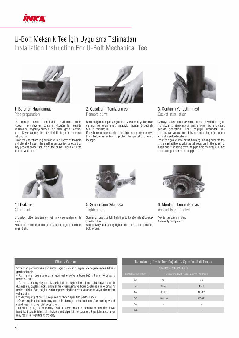
28
U-Bolt Mekanik Tee İçin Uygulama Talimatları Installation Instruction For U-Bolt Mechanical Tee
1. Borunun Haz›rlanmas›Pipe preparation
16 mm’lik delik içerisindeki sızdırmaz conta yüzeyini temizleyerek contanın düzgün bir flekilde oturmasını engelleyebilecek kusurları gözle kontrol edin. Kaynaklanmıfl hat üzerindeki boflluğu delmeye çalıflmayın. Clean the gasket sealing surface within 16mm of the hole and visually inspect the sealing surface for defects that may prevent proper sealing of the gasket. Don’t drill the hole on weld line.
2. Çapaklar›n TemizlenmesiRemove burrs
Boru deliğinde çapak ve çıkıntılar varsa contayı korumak ve sızıntıyı engellemek amacıyla montaj öncesinde bunları temizleyin. If any burrs or slug exists at the pipe hole, please remove them before assembly, to protect the gasket and avoid leakage.
3. Contan›n YerlefltirilmesiGasket installation
Contayı çıkıfl muhafazasına, conta üzerindeki flerit muhafaza iç yüzeyindeki fleritle aynı hizaya gelecek flekilde yerlefltirin. Boru boflluğu üzerindeki dıfl muhafazayı yerlefltirme bileziği boru boflluğu içinde kalacak flekilde hizalayın.Insert the gasket into outlet housing making sure the tab in the gasket line up with the tab recesses in the housing. Align outlet housing over the pipe hole making sure that the locating collar is in the pipe hole.
4. HizalamaAlignment
U cıvatayı diğer taraftan yerlefltirin ve somunları el ile sıkın.Attach the U-bolt from the other side and tighten the nuts finger tight.
5. Somunlar›n S›k›lmas›Tighten nuts
Somunları cıvatalar için belirtilen tork değerini sağlayacak flekilde sıkın.Alternatively and evenly tighten the nuts to the specified bolt torque.
6. Montaj›n Tamamlanmas›Assembly completed
Montaj tamamlanmıfltır.Assembly completed.
Dikkat / Caution
Söz edilen performans›n sa¤lanmas› için c›vatalar›n uygun tork de¤erlerinde s›k›lmas› gerekmektedir.- Afl›r› s›kma, c›vatalar›n zarar görmesine ve/veya boru ba¤lant›s›n›n kopmas›na neden olabilir.- Az s›ma, bas›nç dayan›m kapasitelerinin düflmesine, e¤me yükü kapasitelerinin düflmesine, ba¤lant› noktas›nda akma oluflmas›na ve boru ba¤lant›s›n›n kopmas›na neden olabilir. Boru ba¤lant›s›n›n kopmas› ciddi malzeme zararlar›na ve yaralanmalara yol açabilir.Proper torquing of bolts is required to obtain specified performance.- Over torquing the bolts may result in damage to the bolt and / or casting which could result in pipe joint separation.- Under torquing the bolts may result in lower pressure retention capabilities, lower bend load capabilities, joint leakage and pipe joint separation. Pipe joint separation may result in significant property
Tan›mlanm›fl C›vata Tork De¤erleri / Specified Bolt Torque
ANSI CIVATALARI / ANSI BOLTS
C›vata Ölçüsü/Bolt Size Tan›mlanm›fl C›vata Torku/Specified Bolt Torque
Inch Lbs-Ft. N.m
3/8 30-45 40-60
1/2 80-100 110-135
5/8 100-130 135-175
3/4 - -
7/8 - -

29
Yivli Flanfl İçin Uygulama Talimatları Installation Instruction For Grooved Flange
4. Muhafazan›n YerlefltirilmesiAlignment
Cıvata ve somunları ayırın, muhafaza anahtarları boru conta kanallarına uyacak flekilde muhafazayı boru üzerine geçirin. Cıvatayı yeniden takın ve el ile sıkın.Romove bolts and nuts, place two housings over the gasket, making sure the housing keys fit into the pipe grooves. Re-insert the bolts and hand tighten the nuts.
5. Somunlar›n S›k›lmas›Tighten nuts
Somunları cıvatalar için belirtilen tork değerini sağlayacak flekilde sıkın.Securely tighten nuts alternatively and equally to the specified bolt torque by using spanner.
6. Birleflim Flanfl›n›n Ba¤lanmas›Assembly completed
Flanfl cıvata bofllukları ile birleflim flanflının (veya vana flanflının) cıvata boflluklarını hizalayın. Cıvata boflluğuna standart bir flanfl cıvatası yerlefltirerek el ile somununu sıkın. Birincisinin tersi flekilde bir cıvata daha yerlefltirin ve el ile sıkın. Tüm cıvata bofllukları tamamlanana kadar bu iflleme devam edin. Somunları cıvatalar için belirtilen tork değerini sağlayacak ve flanfl yüzleri paralel olacak flekilde sıkın. Montaj tamamlanmıfltır.Align flange bolt holes with mating flange (or valve) bolt holes. Insert a standard flange bolt through bolt hole and hand tighten a nut. Insert another bolt opposite the first and hand tighten a nut. Continue this until all bolt holes are fitted. Tighten nuts evenly to specified bolt torque, so flange faces remain parallel. Assembly completed.
1. Borunun Haz›rlanmas›Pipe preparation
Boru ucunu, conta kanalı çapının uygun olduğundan, boru ucunda difl olmadığından ve uygun contalama için dıfl çıkıntılar olmadığından emin olmak için kontrol et.Check pipe end for proper groove dimensions and to assure that pipe end is free of indentations and projections that would prevent proper sealing.
2. Contan›n Ya¤lanmas›Lubricate gasket
Boru deliğinde çapak ve çıkıntılar varsa contayı korumak ve sızıntıyı engellemek amacıyla montaj öncesinde bunları temizleyin. Check gasket to be sure it’s compatible for the intended service. Apply thin lubricant to the outside and sealing lips of the gasket.
3. Contan›n YerlefltirilmesiGasket installation
Contayı, conta açılım tarafı A yönüne gelecek flekilde boru ucuna geçirin.Slip the gasket over pipe end, with the gaske opening side towards “A”. Make sure the gaske sealing lip is even with pipe end.
Dikkat / Caution
Söz edilen performans›n sa¤lanmas› için c›vatalar›n uygun tork de¤erlerinde s›k›lmas› gerekmektedir.- Afl›r› s›kma, c›vatalar›n zarar görmesine ve/veya boru ba¤lant›s›n›n kopmas›na neden olabilir.- Az s›ma, bas›nç dayan›m kapasitelerinin düflmesine, e¤me yükü kapasitelerinin düflmesine, ba¤lant› noktas›nda akma oluflmas›na ve boru ba¤lant›s›n›n kopmas›na neden olabilir. Boru ba¤lant›s›n›n kopmas› ciddi malzeme zararlar›na ve yaralanmalara yol açabilir.Proper torquing of bolts is required to obtain specified performance.- Over torquing the bolts may result in damage to the bolt and / or casting which could result in pipe joint separation.- Under torquing the bolts may result in lower pressure retention capabilities, lower bend load capabilities, joint leakage and pipe joint separation. Pipe joint separation may result in significant property damage and serious injury.
Tanımlanmıfl Cıvata Tork Değerleri / Specified Bolt Torque
ANSI CIVATALARI / ANSI BOLTS
Cıvata Ölçüsü/Bolt Size Tanımlanmıfl Cıvata Torku/Specified Bolt Torque
Inch Lbs-Ft. N.m
M10 30-45 40-60
M12 80-100 110-135
M16 - -
M20 - -
M22 - -
M24

30
Hareket Movement
Her bir esnek dizayn edilmifl bağlantı; boru sistemi hareketlerinin, değerlendirilen bağlantı için verilen ölçü ve tipe göre maksimum dizayn seviyesine çıkarılmasına yardımcı olur. Bağlantıda hareket iki faktörle mümkündür:(1) Bağlantı anahtarı ile conta yatağı çapı ve geniflliği arasındaki dizayn aralığına, (2) Bağlantı ile birlefltirilmifl boru uçları arasındaki boflluklara.
Each flexible design coupling can provide for pipe system movement up to the design maximum for the specific size and type coupling being utilized. Movement is possible in the coupling due to two factors: (1) designed- in clearance between the key of the coupling and the groove diameter and groove width, and (2) the gap between pipe ends joined by the coupling.
Doğrusal hareket, bağlantı içerisinde basınç itme kuvveti ve sıcaklık değiflikliklerine tepki olarak boru uçlarının beraber veya ayrı hareket etmesiyle mümkündür. Bağlantı ile birlikte sağlanabilecek doğrusal hareket aflağıda verilmifltir:
Linear movement is accommodated within the coupling by allowing the pipe ends to move together or apart in response to pressure thrusts and temperature changes. The available linear movement provided by couplings is shown below:
Dizayn aralıkları, boru bağlantı noktasında, bağlantı noktasına eksantrik yükler oluflturmayacak flekilde sınırlı bir sapmaya izin vermektedir.Designed-in clearances allow limited deflection of the pipe joint within the coupling, without introducing eccentric loads into the coupling joint.Bağlantı noktalarında izin verilen maksimum açısal hareketler her bağlantı tipi için, performans verilerinde belirtilmektedir. Açısal esneklik miktarları her bağlantı boyutu ve tipi için değiflkenlik göstermektedir. Dizayn kriterleri açısından; boru, conta yatağı ve bağlantı toleransları hesaba katılarak yayınlanan miktarlar aflağıdaki tabloda verilen faktörler bazında azaltılmalıdır.The maximum available angular movement of coupling joints is shown in the performance data for each coupling type. The amount of angular flexibility varies for each coupling size and type. For design purposes the published figures should be reduced by the below listed factors to account for pipe, groove and coupling tolerances.
1. Doğrusal Hareket / Linear Movement
2. Açısal Hareket / Angular Movement
Ölçü / Size 1-11/4 (25-32 mm) 11/2 -12 (40-300 mm)Hareket / Movement 0-4.0 mm 0-6.4 mm
Ölçü / Size 1-3 (inch) 4-12 (inch)Dizayn Faktörü / Design Factor % 50’ye azalt / Reduce to 50% % 75’ye azalt / Reduce to 75%

31
Yiv Oluğu Dizaynı Riser Design
Esnek bağlantılar ile birlefltirilen yiv olukları genelde iki yolla uygulanır. En çok kullanılan yöntemde boru uçları birlefltirme noktalarında birbirlerine örtüfltürülür. Yiv oluğu uygulamalarında, üst boru konmadan önce contanın alt boruya yerlefltirilerek boru ucundan geri çekildiğini unutmayın. Yiv oluklarının sabitlenmesi, boru uçları örtüflükken basınçlama öncesinde veya basınçlama sırasında basınç nedeniyle boru uçları tam ayrılacakken yapılır.Yiv oluğu montajı için bir diğer yöntem ise yiv oluğu sapına ek bir boru parçası yerlefltirilerek boru uçları arasına kalınlığı daha önceden belirlenmifl bir metal ayırıcı yerlefltirmektir. Bu durumda üst boru parçası sabitlenir, metal ayıraç alınır ve birlefltirici monte edilir. Bu yöntem boru bağlantı noktalarında daha önceden belirlenmifl bir boflluk oluflmasını sağlar ve termal nedenlerden ötürü bir hareket beklendiğinde veya basınca dayalı kesme kuvvetinin sert bağlantılara zarar verebileceği sabit kollu (diflli, kaynaklı veya flanfllı) bağlantılı sistemlerde yararlı olabilir.Aflağıdaki örnekler flimdiye kadar karflılaflılmıfl oluk dizaynlarına göre gelifltirilmifl montaj yöntemleridir.Risers assembled with Flexible couplings are generally installed in either of two ways. In the most common method, the pipe ends are butted together within the coupling joint. Note that when installing risers, the gasket is first placed onto the lower pipe and rolled back away from the pipe end prior to positioning the upper pipe. Anchoring of the riser may be done prior to pressur-ization with the pipe ends butted or while pressurized, when, due to pressure thrust, the pipe ends will be fully separated.An alternative method or riser installation is to place a metal spacer of a predetermined thickness, between the pipe ends when an additional length of pipe is added to the riser stack. The upper pipe length is anchored, the spacer removed and the coupling is then installed. This method creates a predetermined gap at each pipe joint which can be utilized in pipe systems where thermal move-ment is anticipated and in systems with rigid (threaded, welded, flanged) branch connections where shear forces due to pressure thrust could damage the rigid connections. The following examples illustrate methods of installing commonly encountered riser designs.
Kollu Bağlantısı Olmayan OluklarBoru uçlarını örtüfltürerek oluğu monte edin. Oluğun tabanına borunun, bağlantıların ve sıvının toplam ağırlıklarını taflıyabilecek bir ankraj yerlefltirin. Her boru parçasında en az, basınç ve termal genleflme neticesinde boru hattı üzerinde bağlantı noktalarında ortaya çıkabilecek bozulmaları engelleyecek boru kılavuzları kullanın.Herhangi bir ara ankraja ihtiyaç olmadığını not edin.Sisteme basınca maruz kaldığında, bağlantı haznesinde yer alan boru uçlarının maksimum oranda ayrıflmasına sebep olan itme basıncı sebebiyle boru çıkıfllarında bir “uzama” meydana gelir. Çıkıflta oluflabilecek maksimum genleflme öncesinden belirlenebilir. (“Doğrusal hareket”e bakınız.) Bu örnekte oluk üzerindeki boru uzunluğu “L”, basınç ve sıcaklık değiflikliklerinden kaynaklanan toplam hareket “M”nin sağlanabilmesi için gerekli sapmayı oluflturacak kadar uzun olmalıdır.
Risers Without Branch ConnectionsInstall the riser with the pipe ends butted. Locate an anchor at the base of the riser (A) to support the total weight of the pipe, couplings and fluid. Provide pipe guides on every other pipe length, as a minimum, to pre- vent possible deflection of the pipe line at the coupling joints as the riser expands due to pressure thrust or thermal growth. Note that no intermediate anchors are required. When the system is pressurized the pipe stack will “grow” due to pres-sure thrust which causes maximum separation of pipe ends within the couplings. The maximum amount of stack growth can be predetermined (see Linear Movement). In this example the pipe length “L” at the top of the riser must be long enough to permit sufficient deflec-tion (see Angular Movement) to accommodate the total movement “M” from both pressure thrust and thermal gradients.

32
Kollu Bağlantılı OluklarOluğu, önceden boflluğunu belirleme yöntemiyle monte edin. Boruyu tabanda veya taban yakınında tüm basınç yükünü, boru ağırlığını ve sıvı ağırlığını taflıyabilecek basınç ankrajı “A” ve oluk üzerindeki basınç ile boru kolonu ağırlıklarını taflıyabilecek ankraj “B” ile ankrajlayın. “A” ve “B” ankrajları arasına “C” ankrajlarını uygulayın. Ayrıca, her bir diğer boru parçasına ara mengeneler yerlefltirin.
Risers with Branch ConnectionsInstall the riser with the predetermined gap method. Anchor the pipe at or near the base with a pressure thrust anchor “A” capable of supporting the full pressure thrust, weight of pipe and the fluid column. Anchor at “B” with an anchor capable of withstanding full pressure thrust at the top of the riser plus weight of pipe column. Place intermediate anchors “C” as shown, between anchors “A” and “B”. Also place intermediate clamps at every other pipe length as a minimum.
Bu sisteme basınç verildiğinde basınçtan kaynaklanan boru hareketi zorlanacak ve kollu bağlantılarda kesme kuvvetleri oluflmayacaktır.
Yanlış Hizalama ve Sapmalar:Borulama düzgün hizalanmadığında esnek birleflimlerin açısal hareket kapasitesi boru bağlantı noktalarının birleflimine katkı sağlamaktadır. Yanal boru hizasızlığı için en az iki adet bağlantı gerekmektedir. Sapma (uzunlamasına hizasızlık), sapma açısı belirli boy ve tip için performans verilerinde sunulan değerleri aflmadığı sürece tek bir bağlantıyla geçifltirilebilir. Bağlantının açısal sapma kapasitesini karflılayabilecek bir boru bağlantı noktası, basınca ve termal yüklere, nasıl yüklendiğiyle alakalı olarak tepki verecektir. Serbest bir bağlantı noktası ise aynı yüklere, doğrularak, yani o noktadaki sapmaları yok etmese de onları azaltarak tepki verecektir. Eğer boru planlamasında sapma hesaba katıldıysa ve mutlaka oluflması gerekiyorsa, yatay yüklere karflı direnmesi ve bağlantı noktasını sapma koflulunda tutması için yeterli sayıda ankrajlama gerekecektir.
Misalignment & Deflections:The angular movement capability of the flexible coupling permits the assembly of pipe joints where the piping is not properly aligned . At least two couplings are required to provide for lateral pipe misalignment. Deflection (longitudinal misalignment) may be accommodated within a single coupling as long as the angle of deflection does not exceed the value shown in the coupling performance data for the particular size and coupling type. A pipe joint that utilizes the angular deflection capability of the coupling will react to pressure and thermal forces dependent upon the manner in which it is restrained. An unrestrained joint will react to these forces by straightening, thus reducing, if not eliminating, the deflection at the joint . If joint deflection has been designed into the pipe layout and must be maintained, then sufficient anchors must be provided to resist the lateral forces and hold the joint in the deflected condition .

33
Eğri Planı:Her bir bağlantı noktası eğrisinde açısal sapma doğrusal boru uzunlukları birleflimleri kullanılarak planlanabilir. Bu örnek eğri yarıçapının, gerekli boru uzunluklarının ve gerekli bağlantı sayısının nasıl hesaplanacağını göstermektedir.R = L/(2 x sin ( ᶿ/2)) L = 2 x R x sin(ᶿ/2) N = T/ᶿBurada;N = Bağlantı sayısı R = Eğri yarıçapı (fit)
ᶿ = Her bir bağlantının merkezden sapması (derece) (Bağlantı performans verilerine bakın, değeri dizayn faktörü ile azaltılacak.)T = Tüm bağlantıların toplam açısal sapması
Curve Layout:Utilizing the angular deflection at each coupling joint curves may be laid out using straight pipe lengths and Couplings. This example shows how to calculate the curve radius, required pipe lengths, and number of required couplings.R = L / (2 x Sin(ᶿ/2)) L = 2 x R x Sin(ᶿ/2) N = T / ᶿWHERE:N = Number of Couplings R = Radius of Curve (feet) L = Pipe Length (feet)
ᶿ = Deflection from centerline (Degrees) of each Coupling (See coupling performance data, value to be reduced by Design Factor)T = Total Angular Deflection of all Couplings.
Boru hattı ana çizgisinden oluflan sapma miktarı aflağıdaki denklemler aracılığıyla hesaplanabilir.M = L sin ᶿᶿ = sin-1 (G÷D) M = (G÷D) x LBurada;M = Hizasızlık (inç)G = Performans verilerinde gösterilen (değeri dizayn faktörü ile azaltılacak olan) izin verilebilecek maksimum boru ucu hareketi (inç)
ᶿ = Performans verilerinde gösterilen (değeri dizayn faktörü ile azaltılacak olan) merkezden minimum sapma derecesiD = Boru dıfl çapı (inç) L = Boru uzunluğu (inç)
The amount of deflection from pipe run centerline can be calculated utilizing the following equations:M =L Sin ᶿᶿ =Sin-1 (G÷D) M =(G÷D) x LWhere:M = Misalignment (inches)G = Maximum Allowable Pipe End Movement (Inches) as shown under “Performance Data” (Value to be reduced by Design Factor)
ᶿ = Maximum Deflection (Degrees) from centerline as shown under “Performance Data” (Value to be reduced by Design Factor)D = Pipe Outside Diameter (Inches) L = Pipe Length (Inches)

34
Hareket - Uygulama Movement-Application
Termal stresTermal stres, hava sıcaklığındaki değifliklikler nedeniyle oluflan genleflme veya daralmalar sonucu ortaya çıkmaktadır. Bir sistem dizayn ederken bu stresi de göz önünde bulundurmanız gerekmektedir. Bu terml hareketin oluflmasına olanak sağlayacak esnek bağlantının yeter sayısına karar verebilmek için aflağıdakileri uygulayın.
Thermal stressThermal stress is caused by changes in temperature, resulting in either expansion or contraction. When designing a system you must allow for this thermal movement. To determine the appropriate number of flexible couplings to allow for this thermal movement please refer to the following.Örnek:- 4 inç 30 m uzunluğunda düz çelik boru.- Her iki uçta da ankrajlanmıfl.- Minimum sıcaklık (montaj sırasında) = 5°C- Maksimum çalıflma sıcaklığı = 55°CTermal genleflme tablosundan, toplam boru hattı uzunluğunun 18 mm (0,71”) artacağını bilmekteyiz. Termal genleflmeyi hesaplamak için Formül 1’i veya aflağıdaki tabloyu kullanabilirsiniz. Bu termal uzama problemi için gereken kaplin sayısını bulmak için;4” esnek bağlantı için izin verilen hareket miktarı: Hareket alanı x Hizalama = İzin verilen hareket 4.3mm x %75 = 3.2mmUygun kaplin sayısı:Termal genleflme / İzin verilen hareket = Bağlantı sayısı 18mm / 3.2mm = 5.6Sonuç:Uygun kaplin sayısı 6’dır.
Example:- 4° straight steel pipe, 30m long- Anchored on both ends- Minimum temperature (during installation) = 5°C- Maximum working temperature = 55°CFrom the thermal expansion table, we know the overall pipeline length will increase by 18mm (0.71”). You can also use Formula 1 or Table 3 to find the amount of thermal expansion. We want to know the number of couplings that are required to address this thermal movement problem.The allowed movement of a 4° flexible coupling is : Movement range x Adjustment = Allowed movement 4.3mm x 75% = 3.2mmThe appropriate number of coupling is:Thermal expansion / Allowed movement = Number of couplings 18mm / 3.2mm = 5.6Conclusion:The appropriate number of coupling is 6.
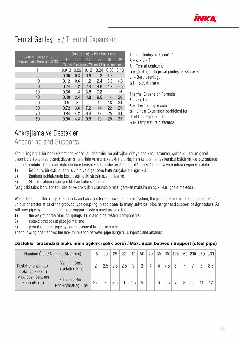
35
Ankrajlama ve Destekler Anchoring and Supports
Termal Genleşme / Thermal Expansion
Kaplin bağlantılı bir boru sisteminde konsollar, destekleri ve ankrajları dizayn ederken, tasarımcı, çokça kullanılan genel geçer boru konsol ve destek dizayn kriterlerinin yanı sıra yataklı tip birleflimin kendisine has karakteristiklerini de göz önünde bulundurmalıdır. Tüm boru sistemlerinde konsol ve destekler aflağıdaki faktörleri sağlamalı veya bunlara uygun olmalıdır:1) Borunun, birlefltiricilerin, sıvının ve diğer boru hattı parçalarının ağırlıkları2) Bağlantı noktalarında boru üzerindeki stresin azaltılması ve3) Stresin salınımı için gerekli hareketin sağlanmasıAflağıdaki tablo boru konsol, destek ve ankrajları arasında olması gereken maksimum açıklıkları göstermektedir.
When designing the hangers, supports and anchors for a grooved end pipe system, the piping designer must consider certain unique characteristics of the grooved type coupling in additional to many universal pipe hanger and support design factors. As with any pipe system, the hanger or support system must provide for1) the weight of the pipe, couplings, fluid and pipe system components;2) reduce stresses at pipe joints; and3) permit required pipe system movement to relieve stress.The following chart shows the maximum span between pipe hangers, supports and anchors.
Destekler arasındaki maksimum açıklık (çelik boru) / Max. Span between Support (steel pipe)
S›cakl›k Fark› (∆T°C)Temperature difference (∆T°C)
Boru Uzunlu¤u / Pipe length (m)
1 5 10 20 30 40
Termal Genleflme / Thermal Expansion (mm)
1 0.012 0.06 0.12 0.24 0.36 0.485 0.06 0.3 0.6 1.2 1.8 2.4
10 0.12 0.6 1.2 2.4 3.6 4.820 0.24 1.2 2.4 4.8 7.2 9.630 0.36 1.8 3.6 7.2 11 1540 0.48 2.4 4.8 9.6 14 2050 0.6 3 6 12 18 2460 0.72 3.6 7.2 14 22 2970 0.84 4.2 8.4 17 25 3480 0.96 4.8 9.6 19 29 39
Termal Genleflme Formül-1λ = α x L x Tλ = Termal genleflmeα = Çelik için do¤rusal genleflme kat say›s› L = Boru uzunlu¤u∆T = S›cakl›k fark›
Thermal Expansion Formula 1λ = α x L x Tλ = Thermal Expansionα = Linear Expansion coefficient for steel L = Pipe length∆T= Temperature difference
Nominal Ölçü / Nominal Size (mm) 15 20 25 32 40 50 70 80 100 125 150 200 250 300
Destekler arasındaki maks. açıklık (m)
Max. Span Between Supports (m)
Yalıtımlı BoruInsulating Pipe
2 2.5 2.5 2.5 3 3 4 4 4.5 6 7 7 8 8.5
Yalıtımsız BoruNon-insulating Pipe
2.5 3 3.5 4 4.5 5 6 6 6.5 7 8 9.5 11 12

36
Esnek Birleflimler: Doğrusal Hareket ve Açısal Hareket Flexible Couplings: Linear Movement and Angular Movement
Boyutlar/DimensionsDo¤rusal Hareket Linear Movemen
Aç›sal HareketAngular MovementNominal Ölçü
Nominal SizeBoru D›fl Çap›
Pipe O.D.mm/inç mm/inç mm/inç (°) mm/inç in/ft
251
33.71.315
2.00.0787
2°-4548
0.58
321½
42.41.660
2.00.0787
2°-1038
0.45
401½
48.31.900
3.20.125
1°-5433
0.40
502
60.32.375
3.20.125
1°-3126
0.32
652½
73.02.875
3.20.125
1°-2725
0.30
652½
76.13.000
3.20.125
1°-1221
0.25
803
88.93.500
3.20.125
1°-0218
0.22
1004
108.04.250
3.20.125
1°-5132
0.39
1004
114.34.500
3.20.125
1°-3628
0.34
Boyutlar/DimensionsDo¤rusal Hareket Linear Movemen
Aç›sal HareketAngular MovementNominal Ölçü
Nominal SizeBoru D›fl Çap›
Pipe O.D.mm/inç mm/inç mm/inç (°) mm/inç in/ft
1255
133.05.250
3.20.125
1°-4130
0.36
1255
139.75.500
3.20.125
1°-1923
0.28
1255
141.35.563
3.20.125
1°-0318
0.22
1506
159.06.250
3.20.125
1°-1823
0.27
1506
165.16.500
3.20.125
1°-0520
0.24
1506
168.36.625
3.20.125
1°-0519
0.23
2008
219.18.625
3.20.125
0°-5015
0.17
25010
27310.750
3.20.125
0°-4012
0.14
30012
323.912.750
3.20.125
0°-3410
0.12

37
Kaplinlerin Hareket Kabiliyeti - Genleflme ve Daralma Bağlantı Noktaları Movement capability of couplings - expansion and contraction joints
Nominal Ölçü Nominal Size
Boru Dıfl Çapı Pipe O.D.
(mm)
İzin Verilen Maks. Hareket Maximum Allowable Movement
(mm)
L min.
(mm)
L max.
(mm)
Kaplin Sayısı Number of Couplings
Su Basıncı (psi) Filled With Water Pressure
1 33.7 45 617 662 10 300
1 1/4 42.4 45 617 662 10 300
1½ 48.3 45 617 662 10 300
2 60.3 45 617 662 10 300
2½ 73.0 45 617 662 10 300
76.1 76.1 45 617 662 10 300
3 88.9 45 617 662 10 300
4 114.3 47 503 550 7 300
139.7 139.7 47 503 550 7 300
5 141.3 47 503 550 7 300
165.1 165.1 52 503 550 7 300
6 168.3 52 591 643 7 300
8 219.1 52 591 643 7 300
10 273.0 52 591 643 7 300
12 323.9 52 591 643 7 300
DESCRIPTION OF GOODS:Bolts and Nuts of Grooved Products
Bolt and Nuts (BN), silver / gold finishedCarbon steel track bolts and carbon steel nuts are produced according specifications of standard ASTM A183Track bolts are defined as grade 2 (heat-treated) and nuts are defined as grade 2 (medium- carbon)
ManufactureThe steel is made by electric-furnace process and BN are produced by cold forging for dimension 3/4” or smaller, and by hot forging for 7/8” or larger.Threads are machined cold rolledBolts are heat-treated by quenching in oil (40-90°C) above the austenitizing temperature (830-880°C) and tempering at temperature higher than 399°CNuts are heat-treated by quenching in oil (40-90°C) above the austenitizing temperature (830-880°C) and tempering at temperature higher than 399°C
Chemical propertiesThe analysis of heat/cast is made from a test sample taken during the pouring of the heat and its chemical composition is conform to the values specified in table At the same time, if needed, the product analysis is conform to the chemical composition values specified in the same table.
MALZEME AÇIKLAMASIYivli Malzemelerin civata ve somunları
Civata ve Somunlar, Gri ve Sarı KaplamaDiflli çelik civatalar ve çelik somunlar ASTM A183 standardına göre üretilir.Diflli civatalar ısıl ifllem görmüfl ve çelik somunlar orta karbonlu olarak tanımlanır.
Üretimİlgili çelik elektrikli fırın prosesi ile üretilir. Civata ve somunlar; 3/4” ve daha küçükölçüler için soğuk dövme, 7/8” ve daha büyük ölçüler için sıcak dövme yöntemi ile üretilir. Difller soğuk haddeleme yöntemi ile açılır.Civatalar (830-880°C) östenit sıcaklığının üzerinde (40-90°C) sıcaklıktaki yağa batırılarak ısıl ifllem yapılır ve 399°C den daha yüksek sıcaklıkta temperlenir.Somunlar (830-880°C) östenit sıcaklığının üzerinde (40-90°C) sıcaklıktaki yağa batırılarak ısıl ifllem yapılır ve 399°C den daha yüksek sıcaklıkta temperlenir.
Kimyasal ÖzelliklerIsıl / döküm analizi sıcak dökme sırasında bir test örneğinden yapılır ve çıkan kimyasal bileflimin değerleri aflağıdaki tabloya uygun olup,Aynı zamanda, ürünün analizi aynı tablo içinde belirtilen kimyasal değerleri ile uyumlu olduğu gözükecektir.
Tensile propertiesThe bolt-nut assembly (full or reduced section as specified in standard ASTM A183), before failure of assembly, is capable of reaching the minimum load specified in standard ASTM A183.
Çekme ÖzellikleriCıvata ve somun montajından önce ASTM A183 standardında belirtilen min. Yük değerlerine dikkat edilmelidir.
In addition, BN meet requirements of ISO 898 (class 8.8) Buna ek olarak, BN ISO 898 (8.8 kalite) gereksinimlerini karflılamalıdır.
Element, %Bolt
Heat-CastS
ProductNut
Heat-CastS
Product
Carbon, min Phosphorus, max Sulfur, max
0.300.040.06
0.270.050.07
0.40-0.550.040.06
0.37-0.580.050.07
Property Minimum required
Tensile strenght, psi (Mpa) Yield point, psi (Mpa) Elongation in 2 inches or 50 mm, 9% Reduction of area, %
110000 (760) 80000 (550)
12 25
Özellik Minimum required
Çekme mukavemeti, psi (Mpa) Kopma Noktası, psi (Mpa)2” veya 50 mm içinde uzaması, 9%Alandaki azalma, %
110000 (760) 80000 (550)
12 25
Element, %Bolt
Heat-CastS
ProductNut
Heat-CastS
Product
Min. Karbon Max. Fosfor Max. Sülfür
0.300.040.06
0.270.050.07
0.40-0.550.040.06
0.37-0.580.050.07
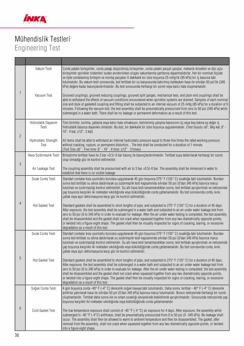
38
Mühendislik Testleri Engineering Test
1
Vakum Testi
Vacuum Test
Conta yataklı birleflimler, conta yatağı düflürülmüfl birleflimler, conta yataklı parçalı flanfllar, mekanik dirsekler ve düz uçlu birleflimler sprinkler sistemleri sudan arındırılırken oluflan vakumlanma flartlarına dayanmalıdırlar. Her bir nominal ölçüde ve tipte contalanmıfl birleflim ve montaj parçaları 5 dakikalık bir süre boyunca 25 inHg’lik (95 kPa) bir iç basınca tabi tutulmalıdır. Bu vakum testi sonrasında, test tertibatı bir su banyosunda batırılmıfl haldeyken hava ile sıfırdan 50 psi’lik (345 kPa) değere kadar basınçlandırılmalıdır. Bu test sonucunda herhangi bir sızıntı veya kalıcı hata oluflmamalıdır.
Grooved couplings, grooved reducing couplings, grooved split flanges, mechanical tees, and plain end couplings shall be able to withstand the effects of vacuum conditions encountered when sprinkler systems are drained. Samples of each nominal size and style of gasketed coupling and fitting shall be subjected to an internal vacuum of 25 inHg (85 kPa) for a duration of 5 minutes. Following the vacuum test, the test assembly shall be pneumatically pressurized from zero to 50 psi (345 kPa) while submerged in a water bath. There shall be no leakage or permanent deformation as a result of this test.
2
Hidrostatik Dayanım Testi
Hydrostatic Strength Test
Tüm birimler, kırılma, çatlama veya kalıcı hata olmaksızın, belirlenmifl çalıflma basıncının üç veya befl katına efl değer iç hidrostatik basınca dayanıklı olmalıdır. Bu test, bir dakikalık bir süre boyunca uygulanmalıdır. (Test boyutu ≤6”, Befl kat; 8” - 10”, 4 kat; ≥12”, 3 kat)
All items shall be able to withstand an internal hydrostatic pressure equal to three-five times the rated working pressure without cracking, rupture, or permanent distortion. . The test shall be conducted for a duration of 1 minute.(Test Size ≤6” . Five time: 8” - 10” . 4 time: ≥12” . 3 times)
3
Hava Sızdırmazlık Testi
Air Leakage Test
Birlefltirme tertibatı hava ile 3 bar +0.5/-0 bar basınç ile basınçlandırılmalıdır. Tertibat suya daldırılarak herhangi bir sızıntı olup olmadığı göz ile kontrol edilmelidir.
The coupling assembly shall be pressurised with air to 3 bar +0.5/-0 bar. The assembly shall be immersed in water to establish that there is no visible leakage
4
Sıcak Conta Testi
Hot Gasket Test
Standart contalar kısa uzunluklu borulara uygulanarak 45 gün boyunca 275° F (135° C) sıcaklığa tabi tutulmalıdır. Bundan sonra test tertibatı su altına daldırılarak su sızdırmazlık testi kapsamında sıfırdan 50 psi (0’dan 345 kPa) basınca maruz tutulmalı ve sızdırmazlığı kontrol edilmelidir. Su altı hava testi tamamlandıktan sonra, test tertibatı ayrıfltırılmalı ve neticesinde çap boyunca karflılıklı iki noktadan sıkıldığında veya büküldüğünde conta çatlamamalıdır. Bu test sonrasında conta, kırık, çatlak veya aflırı deformasyona karflı göz ile kontrol edilmelidir.
Standard gaskets shall be assembled to short lengths of pipe, and subjected to 275° F (135° C) for a duration of 45 days. After exposure, the test assembly shall be submerged in a water bath and subjected to an air under water leakage test from zero to 50 psi (0 to 345 kPa) in order to evaluate for leakage. After the air under water testing is completed, the test assembly shall be disassembled and the gasket shall not crack when squeezed together from any two diametrically opposite points, or twisted into a figure-eight shape. The gasket shall then be visually inspected for signs of cracking, tearing, or excessive degradation as a result of this test.
5
Sıcak Conta Testi
Hot Gasket Test
Standart contalar kısa uzunluklu borulara uygulanarak 45 gün boyunca 275° F (135° C) sıcaklığa tabi tutulmalıdır. Bundan sonra test tertibatı su altına daldırılarak su sızdırmazlık testi kapsamında sıfırdan 50 psi (0’dan 345 kPa) basınca maruz tutulmalı ve sızdırmazlığı kontrol edilmelidir. Su altı hava testi tamamlandıktan sonra, test tertibatı ayrıfltırılmalı ve neticesinde çap boyunca karflılıklı iki noktadan sıkıldığında veya büküldüğünde conta çatlamamalıdır. Bu test sonrasında conta, kırık, çatlak veya aflırı deformasyona karflı göz ile kontrol edilmelidir.
Standard gaskets shall be assembled to short lengths of pipe, and subjected to 275° F (135° C) for a duration of 45 days. After exposure, the test assembly shall be submerged in a water bath and subjected to an air under water leakage test from zero to 50 psi (0 to 345 kPa) in order to evaluate for leakage. After the air under water testing is completed, the test assembly shall be disassembled and the gasket shall not crack when squeezed together from any two diametrically opposite points, or twisted into a figure-eight shape. The gasket shall then be visually inspected for signs of cracking, tearing, or excessive degradation as a result of this test.
6
Soğuk Conta Testi
Cold Gasket Test
4 gün boyunca conta -40° F (-4° C) derecelik soğuk havaya tabi tutulmalıdır. Daha sonra, tertibat - 40° F (-4° C) derecelik antifrize yatırılarak hava ile sıfırdan 50 psi (0’dan 345 kPa) basınca maruz tutulmalıdır. Bunun neticesinde herhangi bir sızıntı oluflmamalıdır. Tertibat daha sonra ılık ve ortam sıcaklığı seviyesinde bekletilerek ayrıfltırılmalıdır. Sonucunda neticesinde çap boyunca karflılıklı iki noktadan sıkıldığında veya büküldüğünde conta çatlamamalıdır.
The low temperature exposure shall consist of -40 °F (-4 °C) air exposure for 4 days. After exposure, the assembly while submerged in -40 °F (-4°C) antifreeze, shall be pneumatically pressurized from 0 to 50 psi (0 -345 kPa). No leakage shall occur. The assembly shall then be allowed to warm to ambient temperature and then be disassembled. The gasket, after removal from the assembly, shall not crack when squeezed together from any two diametrically opposite points, or twisted into a figure eight shape.

39
7
Alev Testi
Flame Test
Test, hava cereyanı bulunmayan bir odada gerçeklefltirilmelidir. Test bağlantısı, test aparatına monte edilir, U biçiminde bükülüdür ve içi suyla doldurulur. Açı, test sonucunda bulunan açı ile efl değer olmalıdır. Sonrasında test bağlantısı sudan arındırılır. Yakıt kabı boru bağlantı noktasının altına merkezleri örtüflecek flekilde yerlefltirilir ve yakıt konularak tutuflturulur. Yanma süreleri; nominal çap<DN 100 için 5 dakika, nominal çap ≥ DN 100 için 8 dakikadır. Düflürücü birleflimler için yanma zamanı daha küçük olan nominal çapa göre belirlenir. Yanma süresi bitiminde (5 veya 8 dakika) alevler anında söndürülmelidir ve tertibat soğutulmalıdır. Soğutma ifllemi için, test bağlantı noktasına buhar çıkmayana dek ama en az 3 dakika boyunca su püskürtülmelidir. Sonrasında test bağlantısı su ile doldurulur ve maksimum izin verilen basınç değerine efl değer bir basınca tabi tutularak sızdırmazlığı gözlenir. Su damlamaları görülebilir ancak akar biçimde su görülmemelidir. Sonrasında bağlantı noktası basıncı serbest bırakılır. (güç ve iç basınç)
The test shall be conducted in a room free from air draught. The test joint is mounted, U-bent on the test apparatus and filled with water. The angle corresponds to the angle documented as a result of the test Subsequently the test joint is drained. The fuel pan is placed centrally below the pipe joint Fuel is filled into the pan and the fuel is ignited. Burning time 5 min for nominal diameters < DN 100; 8 min for nominal diameters ≥’ DN 100 For reducer couplings the dimension of the smaller nominal diameter shall apply for the determination of the burning time. The flame shall be extinguished immediately once the burning time has expired (5 min or 8 min) and the test joint shall be cooled down. For cooling the test joint is immediately sprayed with water until steam formation is no longer visible, but at least for 3 min. The test joint is then filled completely with water and exposed to a test pressure which corresponds to the maximum permissible pressure and is checked visibly for leaks. Water may leak in form of drops, however, not in form of flowing water or a water spray. The test joint is then pressure relieved (force and internal pressure).
8
Çevrim Basınç Dayanımı (Su Darbesi
Testi)
Cycling Pressure Resistance Water
Hammer Test
Çevrim öncesinde tertibat, 5 dakika boyunca çalıflma basıncı değerinde minimum 175 psi’lik (1205 kPa) basınçlı hidrostatik dayanım testine tabi tutulmalıdır ve sızıntı veya çatlama oluflmamalıdır. Tertibata, bu ifllem sonrasında sıfırdan minimum 175 psi’lik (1205 kPa) basınca kadar çıkılarak 20.000 çevrim uygulanmalıdır. Çevrim sonrasında tertibat yeniden hidrostatik dayanım testine tabi tutulmalı ve sızıntı veya çatlama gözlemlenmemelidir.
Prior to the cycling, assemblies shall be subjected to a hydrostatic strength test to the rated working pressure, 175 psi (1205 kPa) minimum, for a duration of 5 minutes. Without leakage or cracking. Assemblies shall then be subjected to 20,000 cycles from zero pressure to the rated working pressure, 175 psi (1205 kPa) minimum. After cycling, the test assembly shall be tested Hydrostatic Strength and maintain 5minutes without leakage and cracking.
9
Sürtünme Kaybının Belirlenmesi
Friction Loss Determination
Birleflim ve montaj ifllemleri öyle ayarlanmalıdır ki, bu noktalardan su geçifline karflı oluflabilecek engellemeler minimum değerlerde kalmalıdır. Birleflim veya montaj noktalarındaki basınç kaybı, birleflim veya montaj elemanı ile aynı nominal çaptaki çelik bir boru için, 20ft/s’lik (6.1 m/s) hız oluflturan bir akımda 5.0 psi’yi (35 kPa) geçmemelidir.
The construction and installation of the coupling or fitting shall be such that obstruction to the passage of water through the coupling or fitting body is minimal. The loss in pressure through the coupling or fitting shall not exceed 5.0 psi (35 kPa) at a flow producing a velocity of 20 ft/s (6.1 m/s) in Schedule 40 steel pipe of the same nominal diameter as the coupling or fitting.
10
Sızdırmazlık Testi - Contasız Tertibat
Leakage Test - Assembly without Gasket
Contasız bir birleflim veya montaj noktasındaki sızıntı, akım kat sayısı (K-faktörü) 5.3 ile 5.8 gal/min (psi) 1/2 [76 - 84 L/min (bar) 1/2] olan çalıflan bir sprinkler baflının sızıntısını geçmemelidir. Bu test, normalde 12 inçe eflit veya altında NPS’lik (300 mm) üst borulamalar için kullanılan nominal boru boyutlarında uygulanır.
Leakage from a gasket-less coupling assembly or fitting shall not exceed that of an operating sprinkler head whose discharge coefficient (K-factor) is 5.3 to 5.8 gal/min(psi)1/2 [76 - 84 L/min/(bar)1/2].This test is for nominal pipe sizes normally associated with over-head piping, less than or equal to 12 in. NPS (300 mm).
11
Burma Testi
Torsion Test
Bu test sadece boru bağlantı noktaları ≤ DN 40 olanlar için geçerlidir. Boru bağlantı noktası su ile doldurularak önce izin verilen maksimum basınç değerine kadar basınçlandırılır, sonra serbest bırakılır. Akabinde bağlantı noktası bir boru ucuna sabitlenir ve diğer uçtan artırılarak burkma ifllemi uygulanır. Basınç uygulanmayan uçta borunun, her iki boru ucu da burkulmayacak flekilde, bir boru ucundan diğerine 80 Nm’lik bir burkulma fliddetini aktarabilmesi gerekmektedir.
This test relates to pipe joints ≤ DN 40 only. The test joint is filled with water and exposed once to the maximum permissible pressure and is then pressure relieved again. Subsequently the test joint is fixed on one pipe end and an increasing torque is applied to the other pipe end. At the pressure- less test joint the pipe joint shall be able to transmit a torque of up to 80 Nm from one pipe end to the other pipe end without any torsion of the pipe ends against each other.
12
Esnek Montaj Parçaları için Esneklik Testi
Flexibility Test forFlexible Fittings
Tertibat belirlenen değere basınçlandırılırken, bağlantı noktasına bu noktayı üretici tarafından belirlenen maksimum açıya getirmek için gerekli bükme momenti uygulanır. Ancak bahsedilen açı nominal boru çapı 8 inçin (203.2 mm) altında olan borular için en az 1 derece, 8 inç (203.2 mm) ve üzeri borular için en az 0.5 derece olmalıdır. Test sonrasında sızıntıya veya hasara karflı gözlemler yapılmalıdır.
In order to evaluate the use of grooved couplings in Earthquake zones 50 through 500 years, test assemblies utilizing flexible couplings and short lengths of steel pipe, in the same nominal size, will be subjected to cyclic testing. The test will deflect the assembly to the manufacturer°Øs maximum recommended angle in the forward and reverse direction for a total 15 cycles with the internal pressure equal to the rated working pressure. There shall be no leakage, cracking, or rupture as a result of this test.
40
13
Sismik Değerlendirme
Seismic Evaluation
Conta yollu birleflimlerin deprem zonlarında 50 ila 500 yıl kullanımının arafltırılması adına esnek birleflimli, kısa uzunluklu ve aynı nominal ölçüde bulunan çelik boru test tertibatları, devinimsel testlere tabi tutulacaktır. Çalıflma basıncı ile uygulanacak test ile birlikte, 15 çevrim sonucunda tertibat ileri ve geri yönlerde üreticinin belirttiği maksimum açıda hareket edecektir. Test sonucunda herhangi bir sızıntı, çatlama veya kırılma görülmemelidir.
In order to evaluate the use of grooved couplings in Earthquake zones 50 through 500 years, test assemblies utilizing flexible couplings and short lengths of steel pipe, in the same nominal size, will be subjected to cyclic testing. The test will deflect the assembly to the manufacturer’s maximum recommended angle in the forward and reverse direction for a total 15 cycles with the internal pressure equal to the rated working pressure. There shall be no leakage, cracking, or rupture as a result of this test.
14
Yanal Yer Değifltirme
Lateral Displacement
Bağıntılı boru ifllerinde, yapılacak tüm testler neticesinde, üreticinin belirlediği sınır açısal ve yanal yer değifltirmeler nezdinde birleflimlerde sızıntı görülmemelidir.
The coupling shall not leak during any of the tests, within the manufacturer°Øs stated limitations for angular deflection or lateral displacement of associated pipework.
15
Hidrostatik Dalgalanma Basıncı Testi
Hydrostatic fluctuation pressure test
Bir baz noktası elde edinilmesi adına birleflim test mekanizması, su ile, 2 dakika +30s/-0s süre boyunca 10 bar ±1 bar gösterge basıncına ulaflılıncaya kadar basınçlandırılmalıdır. Daha sonra tertibat sudan arındırılmalı ve 2 dakika +30s/-0s süre boyunca oluflturulabilecek en yüksek vakum olan 600 mm a/mercury veya -0.8 bar +0 bar/-0.1 bar basınca maruz bırakılmalı ve 5 saniyeden kısa sürmeyecek flekilde atmosferik basınca dönmesi sağlanmalıdır. Sonrasında test mekanizması, su ile 2 dakika+30s/-0s süre boyunca 10 bar ±1 bar gösterge basıncına ulaflılıncaya kadar yeniden basınçlandırılmalıdır. Test boyunca mekanizma sızıntı olup olmadığı yönünde kontrol edilmelidir. En yüksek vakumda ve her basınç seviyesinde boruların göreceli hareket miktarları kaydedilmelidir. Sızıntı oluflmamalıdır.
The coupling assembly shall be pressurised with water to a gauge pressure of 10 bar ± 1 bar for 2min, +30s/-0s to establish a datum. The assembly shall then be drained before being subjected to the greatest vacuum attainable to a maximum of 600 mm a/mercury or –0.8bar +0bar/-0.1 bar for 2min +30s/-0s, and allowed to return to atmospheric pressure in not less than 5s. The assembly shall then be pressurised with water to 10 bar ±1bar for 2 min +30s/-0s. The assembly shall be examined for leakage throughout the test. The relative movement of each pipe shall be recorded at the greatest vacuum and at each pressure. There shall be no leakage.
16
Yangın Testi
Fire Test
Eğer contalı bir boru birleflimi veya montaj elemanı, içeriğinde demir olmayan malzemeler içeriyorsa veya FM standartlarına uygun tasarımın yangına karflı dayanımından flüphe ediliyorsa, o durumda yangın testi uygulamak gerekmektedir. Temsili boyuttaki bir birlefltirilmifl bağlantı befl dakika boyunca 1000°F (535° C) derecelik bir sıcaklıkta yangın ortamına maruz tutulmalıdır. Bu ifllem için tertibat kuru olmalıdır. Süre sonunda anında tertibata, mekanizma el ile tutulacak kadar soğuyuncaya dek su tutulmalıdır. Birleflim veya montaj elemanlarının hiç birisinde çatlama veya kırılma meydana gelmemelidir. Birleflim veya montaj elemanları sonra ayrıfltırılarak sisteme conta ilave edilmelidir. Tertibat yeniden birlefltirilip, ilgili bölümde bahsedildiği flekilde hidrostatik teste tabi tutulup denenmelidir.
If a gasketed pipe coupling or fitting employs non-ferrous materials for its substantial structural components, or if in the judgment of FM Approvals, the design is otherwise suspect with respect to fire resistance, a fire test shall be conducted. A representative size assembled joint without a gasket shall be exposed to a 1000 °„F (538 °„C) fire environment for 5 minutes. The assembly shall be dry for the duration of this exposure. Immediately after the exposure, a water flow shall be introduced through the joint and sustained until the assembly is cool to the touch.No cracking or distortion of any component of the coupling or fitting shall occur. The coupling or fitting shall then be disassembled and the gasket installed. After reassembly, the joint shall be hydrostatically tested, as described in to the hydrostatic test.

�NKA YAPI BAĞLANTI ELEMANLARI SANAY� VE T�CARET A.Ş�stanbul Anadolu Yakası O.S.B Gazi Bulvarı No:7 34953 Tuzla / �stanbul
T: 0216 593 90 00 (pbx) F: 0216 593 90 15
www.inkafixing.com