kochi university of technology academic resource repository_a study of air... · abstract air is...
TRANSCRIPT

Kochi University of Technology Academic Resource Repository
TitleA Study of Air-based Interaction: Input and Hapt
ic Feedback
Author(s) PUTRA, Handityo Aulia
Citation 高知工科大学, 博士論文.
Date of issue 2016-09
URL http://hdl.handle.net/10173/1420
Rights
Text version ETD
Kochi, JAPAN
http://kutarr.lib.kochi-tech.ac.jp/dspace/

A Study of Air-Based Interaction:
Input and Haptic Feedback
Handityo Aulia Putra
A dissertation submitted in partial fulfillmentof the requirements for the degree of
Doctor of Engineering
Kochi University of Technology
2016
Supervisory Committee:
Xiangshi Ren
Yukinobu Hoshino
Masanori Hamamura
Hiroshi Kadota
Kiyoshi Nakahara

Abstract
Air is one of medium that has several properties that has a lot of potential to be used for
developing various novel interaction devices for Human Computer Interactions (HCI). It
has a wide range of use and application that is not limited for standard interfaces but also
specialized interfaces such as for game interfaces and medical interfaces.
Although there have been several research on utilizing air for developing interaction
devices. There are no research that utilize air to provide multiple interaction in one integrated
interface. Therefore we are particularly interested in developing novel devices that capable
to provide multiple interaction options in a single integrated interface, e.g., can work both
as input interface as well as output interfaces.
We designed and developed several novel air-based prototypes using two air properties
which are air-flow and air-pressure. In general, our work is categorized into three applications
that can best leverage the use of air properties and show the significant impact of air-based
device for human computer interaction (i) multimodal interactions (visual and tactile), (ii)
fMRI-compatible interfaces (input and tactile), and (iii) game interfaces (input and tactile).
Through our work we are able to achieve novel interaction devices. We have verified the
benefits of air. We have also confirmed that air can be utilized to provide effective input
and output which can dramatically enhance user engagement and expand new research and
industrial opportunities.
In summary, this dissertation contributes to the field of interaction technologies by ex-
panding possibilities and interaction bandwidth of air-based interaction devices. The con-
clusion drawn and designs proposed will benefit future research studies not only in the field
interaction technologies but also in the field of brain science and game interaction. Our
work will also have important implications for providing valuable user interfaces for bet-
ter education, data visualization, medical/rehabilitation, and entertainment (game, virtual
reality).

TABLE OF CONTENTS
Page
List of Figures . . . . . . . . . . . . . . . . . . . . . . . . . . . . . . . . . . . . . . . . . . . . iii
List of Tables . . . . . . . . . . . . . . . . . . . . . . . . . . . . . . . . . . . . . . . . . . . . vi
Chapter 1: Introduction . . . . . . . . . . . . . . . . . . . . . . . . . . . . . . . . . . . . 1
1.1 Research Background . . . . . . . . . . . . . . . . . . . . . . . . . . . . . . . . . . 1
1.2 Research Issues and Objectives . . . . . . . . . . . . . . . . . . . . . . . . . . . . 1
1.3 Dissertation Overview . . . . . . . . . . . . . . . . . . . . . . . . . . . . . . . . . . 2
Chapter 2: Literature Review . . . . . . . . . . . . . . . . . . . . . . . . . . . . . . . . . 5
2.1 Interaction Technology . . . . . . . . . . . . . . . . . . . . . . . . . . . . . . . . . 5
2.2 Air-based Interaction Technology . . . . . . . . . . . . . . . . . . . . . . . . . . . 5
2.3 Summary of Research Gap . . . . . . . . . . . . . . . . . . . . . . . . . . . . . . . 6
Chapter 3: Air-Based Multi-modal Interactions . . . . . . . . . . . . . . . . . . . . . . 8
3.1 Introduction . . . . . . . . . . . . . . . . . . . . . . . . . . . . . . . . . . . . . . . . 8
3.2 Related Work . . . . . . . . . . . . . . . . . . . . . . . . . . . . . . . . . . . . . . . 9
3.3 AirVis - Air Based Visual and Tactile Display . . . . . . . . . . . . . . . . . . . 12
3.4 User Study on Effect of Visual Condition on Users’ Air-Haptic Perception . . 17
3.5 Discussion . . . . . . . . . . . . . . . . . . . . . . . . . . . . . . . . . . . . . . . . . 22
Chapter 4: Novel Air-based MRI-Compatible Interaction Devices . . . . . . . . . . . 26
4.1 Introduction . . . . . . . . . . . . . . . . . . . . . . . . . . . . . . . . . . . . . . . . 26
4.2 Related Work . . . . . . . . . . . . . . . . . . . . . . . . . . . . . . . . . . . . . . . 28
4.3 Air-flow-based system fMRI Input Device . . . . . . . . . . . . . . . . . . . . . . 30
4.4 Novel Air-Pressure-Based fMRI-Compatible Interface Devices . . . . . . . . . . 32
4.5 fMRI-compatibility evaluation . . . . . . . . . . . . . . . . . . . . . . . . . . . . . 39
i

4.6 MRI-Compatibility Results . . . . . . . . . . . . . . . . . . . . . . . . . . . . . . . 40
Chapter 5: Air-based Game Interactions . . . . . . . . . . . . . . . . . . . . . . . . . . 44
5.1 Introduction . . . . . . . . . . . . . . . . . . . . . . . . . . . . . . . . . . . . . . . . 44
5.2 Related Work . . . . . . . . . . . . . . . . . . . . . . . . . . . . . . . . . . . . . . . 45
5.3 Development of Air-Based Interface . . . . . . . . . . . . . . . . . . . . . . . . . . 46
5.4 User Study . . . . . . . . . . . . . . . . . . . . . . . . . . . . . . . . . . . . . . . . 48
5.5 Results and Analysis . . . . . . . . . . . . . . . . . . . . . . . . . . . . . . . . . . . 51
5.6 Discussion and Future Work . . . . . . . . . . . . . . . . . . . . . . . . . . . . . . 55
Chapter 6: General Conclusion and Future Directions . . . . . . . . . . . . . . . . . . 57
6.1 Summary of Contributions . . . . . . . . . . . . . . . . . . . . . . . . . . . . . . . 57
6.2 Future Research Direction . . . . . . . . . . . . . . . . . . . . . . . . . . . . . . . 58
ii

LIST OF FIGURES
Figure Number Page
1.1 Dissertation overview. . . . . . . . . . . . . . . . . . . . . . . . . . . . . . . . . . . 2
3.1 The AirVis prototype. (a) the user (hand) feels air-tactile sensation fromthe top of the device, (b) Multiple balls levitated to form a simple line, (c)Multiple balls form a simple pattern, with fan-motor noise around 58 decibels(dB). . . . . . . . . . . . . . . . . . . . . . . . . . . . . . . . . . . . . . . . . . . . . 8
3.2 The components of AirVis. (a) The prototype circuitry diagram, showing oneof 16 PWM circuits for fan-motors, (b) the AirVis prototype and controller,(c) AirVis consists of a fan-motor array at the bottom of transparent box(body) which generate air flow to levitate balls and provide touch sensationfrom the top of the box. . . . . . . . . . . . . . . . . . . . . . . . . . . . . . . . . . 13
3.3 Nozzle effect test, (a) various nozzle with different height and angle, (b) il-lustration of nozzle dimension with h = nozzle height and α = nozzle angle,and (c) air flow force measurement setup (AirVis is put upside down andperpendicular to digital scale, with changeable distance). . . . . . . . . . . . . . 15
3.4 Measured average height of the ball (cm) over time (ms) with two regressionlines (linear and quadratic) . . . . . . . . . . . . . . . . . . . . . . . . . . . . . . . 16
3.5 Illustration of Experimental conditions. (a) The user wears a Headphone fornoise canceling and the hand is supported by a structure in the no visual cuecondition (no ball and no monitor), (b) A list of shapes was used in the userstudies (12 different patterns consisted of 8 simple lines, 2 composite lines, 2diagonal lines), (c) The tactile only condition, no-visual cue (NV), (d) Tactilewith computer graphic (CG) on monitor as the visual cue (VM), (e) Tactilewith levitated balls as the visual cue (VB). . . . . . . . . . . . . . . . . . . . . . 17
3.6 Summary of the effect of distance between user’s hand and AirVis to the user’stactile perception in percentage, NV = No Visual, VM = Visual on Monitor,VB = Visual using Ball movement. . . . . . . . . . . . . . . . . . . . . . . . . . . 21
3.7 Summary of user evaluation on AirVis. . . . . . . . . . . . . . . . . . . . . . . . . 23
iii

4.1 Various air-based devices. (a) 3D printed air-flow based device for tap andslide interaction, (b) a pneumatic pedal device constructed from two pneu-matic balls, wood, and PVC tube, (c) pneumatic joystick which can be usedto manipulate x-y movements, (d) Pneumatic button with four pressure sen-sitive buttons, constructed from four air pockets arranged in a 3D printedstructure, (e) a two button pneumatic device, constructed using a single airpocket with 3D printed structure, (f) two 3D printed soft pneumatic buttonput together as wearable soft-haptic device . . . . . . . . . . . . . . . . . . . . . 26
4.2 fMRI-Compatible air-flow-based system, (a) a participant uses an air-flow-based device to control the ball position positioned outside fMRI room (b)from inside of the fMRI scanner, (b) air-flow-based system consisting of atransparent tube and a ball. . . . . . . . . . . . . . . . . . . . . . . . . . . . . . . 28
4.3 Schematic diagram of air-flow based system. . . . . . . . . . . . . . . . . . . . . 30
4.4 Interaction for fMRI-Compatible air-flow-based system, (a) open interactionto lift the ball by allowing air-flow, (b) close interaction to put the ball down bystopping air-flow, and (c) slide interaction for precise control of ball positionby controlling the amount of air-flow. . . . . . . . . . . . . . . . . . . . . . . . . . 31
4.5 Pneumatic and circuitry diagram for general design of pneumatic-based fMRI-compatible devices. . . . . . . . . . . . . . . . . . . . . . . . . . . . . . . . . . . . 32
4.6 Pneumatic and circuitry diagram for delivering smell to users inside fMRIscanner. . . . . . . . . . . . . . . . . . . . . . . . . . . . . . . . . . . . . . . . . . . 33
4.7 Three basic air pocket/chamber for pneumatic system a four-button pneu-matic device, (a) an air-pocket fabricated by plastic welding, (b) a soft buttonfabricated by 3D printer with flexible material, (c) a hand squeeze devicebuilt from off-the-shelf lens blower and teflon tape, (d) a freshly printed four-button flexible pneumatic device with mesh supporting structures, (e) finished3D printed four-button flexible pneumatic device . . . . . . . . . . . . . . . . . . 34
4.8 Complete Pneumatic System. . . . . . . . . . . . . . . . . . . . . . . . . . . . . . 36
4.9 (a) Pedal simulation device which consisted of acceleration and brake pedals,(b) Experimental setup inside MRI device. . . . . . . . . . . . . . . . . . . . . . 37
4.10 Experiment in the fMRI room and result images. a) The pneumatic devicewas put on the fMRI bed to be tested, b) a view of the pneumatic device whilethe fMRI was running. . . . . . . . . . . . . . . . . . . . . . . . . . . . . . . . . . 40
4.11 Structural image scan result. (a) without the pneumatic device, (b) the pneu-matic device inside the fMRI scanner off condition, (c) the pneumatic deviceinside the fMRI scanner on condition. . . . . . . . . . . . . . . . . . . . . . . . . 41
iv

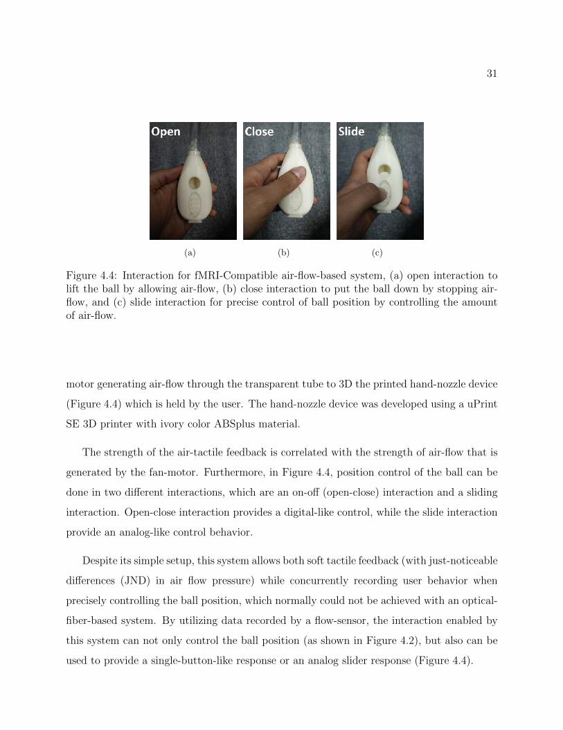
4.12 Noise image scanning sequences result. (a) without the pneumatic device, (b)the pneumatic device inside the fMRI scanner off condition, (c) the pneumaticdevice inside the fMRI scanner on condition. . . . . . . . . . . . . . . . . . . . . 42
4.13 EPI scan result. (a) without the pneumatic device, (b) the pneumatic deviceinside the fMRI scanner off condition, (c) the pneumatic device inside thefMRI scanner on condition. . . . . . . . . . . . . . . . . . . . . . . . . . . . . . . 43
4.14 tSNR results. (a) without the pneumatic device, (b) the pneumatic deviceinside the fMRI scanner off condition, (c) the pneumatic device inside thefMRI scanner on condition. . . . . . . . . . . . . . . . . . . . . . . . . . . . . . . 43
5.1 Complete system of AirDevice. . . . . . . . . . . . . . . . . . . . . . . . . . . . . 46
5.2 Diagrams of AirDevice, (a) electronic diagram of AirDevice, (b) pneumaticconnection of AirDevice. . . . . . . . . . . . . . . . . . . . . . . . . . . . . . . . . 46
5.3 a) Keyboard, b) Gamepad, c) AirDevice. . . . . . . . . . . . . . . . . . . . . . . 48
5.4 Interface of the simple games; (a) flappy bird (copter) like game, (b) two-linerhythm game. . . . . . . . . . . . . . . . . . . . . . . . . . . . . . . . . . . . . . . . 48
5.5 Experimental setup; (a) playing game using keyboard, (b) playing game usingAirDevice. . . . . . . . . . . . . . . . . . . . . . . . . . . . . . . . . . . . . . . . . 50
5.6 Performance parameter for repetition 1 to 5, mean score (a), error rate (b). . . 54
v

LIST OF TABLES
Table Number Page
3.1 Effect of different nozzles to air flow force from multiple distances(Dis). Mea-sured using digital scale in 0.000 gram. (NT = No transparent tube, T = withtransparent tube attached. T, h, α = with transparent tube, nozzle height(h),nozzle angle(α)). . . . . . . . . . . . . . . . . . . . . . . . . . . . . . . . . . . . . . 25
5.1 Total immersion and its components when playing using Keyboard(K), Gamepad(G),and AirDevice(A). . . . . . . . . . . . . . . . . . . . . . . . . . . . . . . . . . . . . 52
5.2 Mean scores of USE components . . . . . . . . . . . . . . . . . . . . . . . . . . . 53
vi

ACKNOWLEDGMENTS
I would like to express sincere appreciation to Kochi University of Technology who had
given me the research opportunity.
I would like to thank my advisor, Xiangshi Ren, and express gratitude for his guidance
and support.
I would like to thank my committee members, Yukinobu Hoshino, Masanori Hamamura,
Hiroshi Kadota and Kiyoshi Nakahara for their valuable feedback throughout the project.
I would like to thank John Cahill for helping my writings.
I would like to thank the members of the Ren lab for their support, especially Chaky his
enormous supports.
I would like to thank my parents, Zaidir and Jasmaniar, my wife Reisa Rahmatu Dewi
for all their support.
vii

DEDICATION
to my dear mother, Jasmaniar
viii

1
Chapter 1
INTRODUCTION
1.1 Research Background
Interaction technologies play an important role in Human-Computer Interaction (HCI) and
have important connection with other fields such as education [34], medical care (e.g., re-
habilitation) [16], video games [12], and data visualization [38]. Engaging technologies can
improve human well-being and quality of life [8, 69]. Conventional interaction devices such as
keyboard, mouse, and touch interfaces have limited options in providing engaging interaction
to users. Thus, a large body of HCI work focuses on engaging technologies, such as tangible
interfaces [29, 59], non-contact tactile interfaces [19, 26], and multi-modal interfaces [31, 55].
1.2 Research Issues and Objectives
Air is one good medium to provide engaging user interfaces. Some studies recently have
explored the use of air for user interfaces [36, 53, 54]. Although air have been utilized as a
medium to develop various devices and robots, most past works mainly focus on providing
output interaction [13, 19, 63, 78]. To our knowledge little work has explored the use of air to
provide input, multiple-channel output, or both input and output simultaneously through a
single medium. Specifically, most of existing devices utilized compressed air and convert its
energy into mechanical motion through pneumatic actuators. This method severely limits
how air can be utilized to provide interaction between human and computer, especially for
input. This is because there was little exploration of the capabilities of air properties and
limited resources that could facilitate the development of air-based interaction devices.
This work aims to leverage the use of air for novel interaction. We are the first to

2
comprehensively explore and study the use of air for both input and output interaction.
To increase the interaction bandwidth and choices of air-based interaction devices, this
dissertation leverage the use of air properties to demonstrate the use of air as interaction
technologies in three scenarios: a) Multimodal interaction, b) fMRI interaction, and c) game
interaction.
The outcomes of this dissertation are:
1. An understanding of air properties for designing input interactions and haptic feed-
backs.
2. Several new air-based interaction devices.
3. Practical guidelines for interaction device design for multi-modal, MRI, and game
interactions.
1.3 Dissertation Overview
Figure 1.1: Dissertation overview.
1. In order to investigate the capability of air for multimodal interaction, we explored
the suitability of air-properties to concurrently generate non-contact tactile sensations

3
with dynamic physical visualization. Additionally, we explored the ability of air flow
force to create the sensation of patterns. The distinguishing feature of our prototype is
that it can generate multi-point tactile stimuli and augment it with additional direct
visual perception (i.e., physical visualization).
Moreover, to understand the effect of different visual feedback condition to user percep-
tion of non-contact tactile feedback, we conducted a systematic user study. The study
also considers haptic perception on different haptic feedback patterns and various hand
positions i.e., the significance of distance from the top of the device.
From this study we found out that air can be used to provide a significantly high detec-
tion rate by all participants in determining the position and/or the pattern generated.
Moreover, the study results indicate that the direct visual perception of our prototype
enhances the user’s tactile perception level compared to other visual conditions.
2. Some parts of air-device were found to be invulnerable to electromagnetic interference
EMI. Thus we proposed the use of air-based device for MRI environment which is a
specialized application that is very sensitive with EMI. The strong magnetic field of
functional magnetic resonance imaging (fMRI) and the supine position (lying with the
face up) of participants in fMRI scanners severely limit how participants can interact
during fMRI experiments.
Despite its simple setup, air-based system is able to provide soft tactile feedback and
record user responses/behaviors, which normally could not be achieved with an optical-
fiber-based system. Additionally, the developed air-based prototypes comply with
safety standard of fMRI-compatible devices. We also confirm that the prototypes
can be used for continuous input device and also for giving soft tactile sensation con-
currently. We also have provided several design consideration to develop air-based
interaction device for use in fMRI environment. Furthermore, we proposed some ap-
plications of the prototypes.

4
3. Throughout the studies, we found that air-based devices are capable to provide multi-
modal interactions and also able to be used to develop various novel interaction device
for fMRI environment enabling new kind of brain experiments which are previously
difficult to do without the air-devices.
In this dissertation, one of our goal is to design and develop engaging interaction
devices. Thus, we conducted a study to investigate whether air-based devices can
engage users. We chose to investigate air-based device as a game interaction device
since playing computer games is an enjoyable activity that is loved by many people.
This study compared engagement and usability between a keyboard, a gamepad and
air-based device.
Our comparison with keyboard and gamepad found that air-based device outperformed
other devices in immersion and fun, was well-accepted by participants, and can achieve
equal performance after five trials of training. This suggests that air pressure can serve
as a promising input for game interaction and can provide new forms of play.

5
Chapter 2
LITERATURE REVIEW
In this chapter, we discuss (i) interaction technologies for human computer interaction,
(ii) air-based interaction technologies, and the current research gap.
2.1 Interaction Technology
Research in Human-Computer Interaction (HCI) has been very successful and has fundamen-
tally changed computing [47]. The term of interaction technology is that all of technologies
that help bridge human and computer or computing machines to communicate and interact
with each other. There are some type of interaction technologies that emphasize on soft-
ware/application such as drawing program [6], text editing program [45], hypertext [50], and
video games [74].
Interaction technology is not limited to software only but also some physical interaction
device such as keyboard or mouse or gamepad. Technologies that have supported interac-
tion between human and computer have evolved from direct manipulation [62] into natural
interaction and gestural recognition [41].
A well designed and developed interaction technologies whether it is a software or a device,
it can better improve the performance of the users in conducting their tasks. Therefore, a
good interaction technology is a technology that can make the users enjoy and engaged while
doing their tasks.
2.2 Air-based Interaction Technology
There are very wide variety of interaction technologies existing currently. This dissertation
focuses on utilizing air-properties as a medium for designing and developing an engaging and

6
useful interaction devices. Air as a medium have several properties such as air flow and air
pressure that can be leveraged to provide interaction between human and computers.
Utilizing air pressure to develop interactive devices have been exemplified by several
researchers, e.g., jamming interface [14], visual display with dynamic button [22], inflatable
mouse [35], Pneui [76], robot interaction [60].
Suzuki et al. [63, 64] introduced their design of a tactile feedback device which utilizes
air pressure to produce the feedback. Their main concern was to provide a tactile feedback
device that places no restraints on the users, e.g. wires, rigid arms. Furthermore, their
system controls the air jet according to the position of the air receiver, which is held by the
users. Their system freed users from the restraints of wires, however the users needed to
hold an air receiver stick to receive the tactile feedback. Hachisu et al. [20] utilize air suction
instead of air an jet to provide tactile feedback. However, users still need to touch the suction
surface to feel the feedback. Therefore it can not be considered to be a fully non-touch tactile
device. Another devices that utilize air for tactile feedback has been developed by Gupta et
al.[19] and Sodhi et al. [61]. Instead of using air jets, they use air vortex rings for tactile
feedback and this device projects the air directly onto the users. Therefore users can feel
tactile feedback without the need to touch or hold anything.
While there are already extensive amount of devices that utilized air properties to provide
interaction between human and computer, current air-based interaction technologies only
focus in generating feedback.
2.3 Summary of Research Gap
Our literature review revealed that there are considerable amount of researches have been
done in utilizing air for interaction technologies. Despite this, current air-based interaction
technologies are very limited in only providing single feedback (output) to user. There
is a need to explore and investigate the capabilities of air for not only generating output
or feedback but also to receive and record input interactions from users. Our review also
revealed that air-based interaction technology have a huge potential for developing various

7
novel interaction devices that enable unique interactions that were limited previously. This
dissertation seeks to address these two research gaps and propose new interaction devices
that further leverage the advantages of air properties.

8
Chapter 3
AIR-BASED MULTI-MODAL INTERACTIONS
3.1 Introduction
Physical visualization can provide more engaging user experience, however the main chal-
lenge for visualizing data using physical objects is representing changes in data dynamically.
Although some works [15, 51, 52] tackled this limitation by using a matrix of actuated
columns or acoustic levitation, touching a levitated object directly can disturb and occlude
visual perception of the physical visualization. Thus, there is a need for tactile awareness
without directly touching and disturbing the feedback with the user’s hand. Some previous
works provided non-contact tactile sensation by using air [19, 61, 63] and ultrasound [7, 27].
However, these devices are dedicated to generating non-contact tactile sensations only and
(a) (b) (c)
Figure 3.1: The AirVis prototype. (a) the user (hand) feels air-tactile sensation from thetop of the device, (b) Multiple balls levitated to form a simple line, (c) Multiple balls forma simple pattern, with fan-motor noise around 58 decibels (dB).

9
they do not support this with direct visual feedback (i.e., physical visualization).
In order to present the suitability of air-properties for multi-modal interaction by con-
currently generating non-contact tactile sensations with dynamic physical visualization, we
developed a prototype named AirVis: an air-based physical visual and tactile display (Figure
3.1). We evaluated the design and technical challenge of developing an air-based multi-modal
device. Furthermore, to understand efficiency and application of AirVis, we conducted a user
study, we focused on investigating effect of multi-modal feedback (visual and touch) to user
performance.
3.2 Related Work
This work focused on developing a device that can concurrently provide (1) physical vi-
sualization, and (2) non-contact tactile sensation, where the non-contact tactile sensation
delivers a multi-point representation of the pattern of the physical visualization.
3.2.1 Physical Visualization
Ultrasound is able to provide either physical visualization [51, 52] or non-contact tactile feed-
back [7, 27]. However, the core limitation of ultrasound is that the same array of ultrasound
can not concurrently provide both physical visualization and non-contact tactile feedback.
For concurrent visual feedback and tactile sensation, air is a promising method. In order
to allow tactile sensation without occluding the physical visualization, a common approach
is to provide the sensation in mid-air, separated from the visualization. For example, aerial
tunes [3] levitate a light-weight ball in mid-air using a stream of air flow, thus enabling
interaction with the levitated object. However, these devices are limited to only one object
with a single point of tactile sensation, thus it cannot represent 3D data. Our work will fill
this gap.
One challenge of using air to provide multipoint sensation is that air tends to spread
around, thus we need to find ways to focus the air to provide a consistent tactile sensation.
A single air source like that in Air Jet [63] or Aireal [61] would not apply in this case. Our

10
solution is to represent each air source as one pixel, similar to the concept used in inForm
[15] where a matrix of individual manipulable columns are used to represent different 3D
information dynamically.
3.2.2 Non-Contact Tactile Sensation
Several works regarding non-touch tactile devices have been conducted. They can be classi-
fied into three classes based on their approaches: 1) ultrasound devices, 2) magnetic devices,
and 3) air devices.
Ultrasound device
To the best of our knowledge, Iwamoto et al. [30] pioneered the work of non-touch meth-
ods for producing tactile feedback using ultrasound sound pressure. Later on, Hoshi et al.
[26] improved the prototype by increasing the number of ultrasound transducers and by
controlling the phase delay of the ultrasound transducers. Moreover, Hoshi et al. devel-
oped Touchable Holography [27], an aerial interaction system [24], and remote hand-writing
system [25].
Carter et al. [7] expanded the ultrasound device to achieve multi-point feedback and
developed UltraHaptics, a multi-point mid-air tactile feedback system for touch surfaces.
Multi-point feedback is achieved by modulating multiple focal points at the same time.
However, the pressure strength of the feedback diminished with the increasing number of
focal points [73].
Ciglar [9] proposed the of ultrasound tactile feedback as a musical instrument. Alexander
et al. [2] combined an ultrasound tactile device with a mobile TV and discussed its design
constraints. Marshall et al. [42] developed Ultra-Tangibles and demonstrated an interactive
table on which tangible objects can be freely moved.
Although the effective distance of ultrasound non-touch tactile devices is limited to 200-
300 mm from the transducer surface, they have high spatial resolution compared to other
non-touch tactile devices, e.g., air, magnetic. However, ultrasound non-touch tactile devices

11
have the highest system complexity due to the high number of transducers used in their
systems. Ultrasound tactile devices also need to focus the radiation pressure of several
ultrasound transmitters to produce adequate radiation pressure.
Magnet device
Although their device is not completely non-touch, Lee et al. [39] and Weiss et al. [71]
utilized magnets to produce mid-air tactile feedback. Weiss et al. [71] developed FingerFlux
which utilizes magnetic force to generate tactile feedback. Attracting and repelling magnets
arranged in a matrix, can create physical constraints on the table surface without using any
physical devices. Though this requires no contact with the system, the feedback is limited
to near the table surface, and users are required to wear or carry dedicated hardware due to
the characteristics of the magnets which create the attract-repel forces.
Air device
Suzuki et al. [63, 64] introduced their design of a tactile feedback device which utilizes air
pressure to produce the feedback. Their main concern was to provide a tactile feedback
device that places no restraints on the users, e.g. wires, rigid arms. Furthermore, their
system controls the air jet according to the position of the air receiver, which is held by
the users. Their system freed users from the restraints of wires, however the users needed
to hold an air receiver stick to receive the tactile feedback. Hachisu et al. [20] utilize air
suction instead of air an jet to provide tactile feedback. However, users still need to touch
the suction surface to feel the feedback. Therefore it can not be considered to be a fully
non-touch tactile device.
Another devices that utilize air for tactile feedback has been developed by Gupta et
al.[19] and Sodhi et al. [61]. Instead of using air jets, they use air vortex rings for tactile
feedback and this device projects the air directly onto the users. Therefore users can feel
tactile feedback without the need to touch or hold anything.

12
The air vortex device is considered to be low cost and low complexity. However, it can
only project one single-point air vortex at a time and the doughnut-shaped shape perception
is fixed. Air devices appear to be the most economical and least complex compared to
ultrasound devices and magnetic devices.
Summary
In summary, there is a large number of studies that utilized ultrasound tactile devices for
their systems but only a small number of studies that utilized air or magnetic devices. We
found that there is no device like our prototype which has the following features, 1) low-
cost1, 2) multi-point non-touch tactile feedback, and 3) non-touch tactile feedback and visual
feedback simultaneously.
3.3 AirVis - Air Based Visual and Tactile Display
AirVis is designed to levitate objects and generate air-tactile sensations concurrently us-
ing an individual air flow. Figure 3.2 shows that AirVis consists of arrays of transparent
boxes/bodies which consist of an object inside and a fan-motor at the bottom. An array
of fan-motors generate air-flow upward to push and levitate the objects. The generated
air-flow exits through an opening at top of the box giving a soft sensation of touch to users
hand/palm.
3.3.1 Hardware specification
Figure 3.2a shows a diagram of circuitry for the AirVis. AirVis consists of sixteen 25 × 25
mm2 fan-motors in a 4x4 array with a specification of 5v, 0.21A, and 2000 rpm each. All of
the circuits and fan-motors are driven by a 5v, 10A switching power supply. The complete
prototype of AirVis is shown in Figure 3.2b.
1E.g., the cost of materials to build our prototype which consisted of an acrylic body, Styrofoam balls,fan-motors, Arduino, motor-shields, and power supplies was around 200-250 US Dollars (128-160 GBP).

13
The Arduino Uno microcontroller receives patterns and location information for each
fan-motor from a PC via serial communication. Adafruit Motor shield then translate the
information and sends the PWM signals to all the fan-motors through PWM circuits. The
prototype allows the control of an individual ball or a group of balls forming a pattern using
a keyboard or mouse.
Each PWM circuit consisted of an NPN transistor (C1815), a 1kΩ, and a diode (N4007).
This circuit enables the control of motor speed by PWM (duty cycle of square wave). An
N4007 flyback diode is added to protect the circuit from inductive current that may occur
when the motor is stopped.
The current AirVis prototype uses light-weight balls to construct the physical visualiza-
tion. In pilot studies, different sized balls (diameter of 13, 15, 18, and 20 mm) and different
sized transparent body tubes (18 × 18 and 25 × 25 mm2) were tested. The balls weighed
1.04, 1.60, 2.76, and 3.79 g respectively. Identical fan-motors were used for all tests. Pilot
studies showed that increasing the ball size required an increase in the power needed to lev-
itate the ball. It is recommended to use a ball that has a diameter similar to the size of the
transparent body inner diameter, with less than 6 mm and more than 2-3 mm in difference.
(a) (b) (c)
Figure 3.2: The components of AirVis. (a) The prototype circuitry diagram, showing one of16 PWM circuits for fan-motors, (b) the AirVis prototype and controller, (c) AirVis consistsof a fan-motor array at the bottom of transparent box (body) which generate air flow tolevitate balls and provide touch sensation from the top of the box.

14
The larger diameter of the tube permits air to flow around the ball causing it to spin quickly
and create turbulence inside the tube, making it difficult to levitate the ball. Conversely, if
the difference in diameter is very small (less than 2 mm) or the ball fits too tightly inside
the transparent tube, the ball will touch the inner wall of the tube adding resistance to the
air flow that levitates the ball. Based on pilot studies, AirVis is constructed using arrays of
balls with 20 mm diameter and transparent tubular bodies which are 200 mm in height with
a 25 mm inner diameter following the diameter of the fan-motors in order to minimize air
flow leakage.
3.3.2 Modular Design
In order to achieve higher resolution in the future, AirVis is designed to be scalable, i.e.,
the number of fan-motors and its transparent body can be increased and reduced as needed.
The 16-channel Adafruit Motor shield is stack-able which allows us to use multiple motor-
shields with a maximum number of 32 motor-shields controlled by a single Arduino. This
motor-shield characteristic allows AirVis to be expanded to a maximum of 512 motors for a
single Arduino.
3.3.3 Air Flow Force
Air-tactile sensation is closely related to air flow force that exits from the top of AirVis (Fig-
ure 3.2c). In order to understand how strong the emitted air-flow force is, a measurements of
air-flow force were conducted using a digital weight scale with 0.000 gram precision. AirVis
was set upside-down and perpendicular to the weight scale. A smaller version of AirVis (2
× 2 pixels) was used, as it was easier to hold it upside down. The distance between weight
scale and AirVis can be adjusted to measure the effect of different distance to the air flow
force.
Without properly focusing the air, air will be increasingly dispersed from the top of AirVis
and the air flow force will decline. Therefore, several nozzles with different height and angle
(Figure 3.3a and Figure 3.3b) were developed to focus the air flow force and enhance the

15
Figure 3.3: Nozzle effect test, (a) various nozzle with different height and angle, (b) illus-tration of nozzle dimension with h = nozzle height and α = nozzle angle, and (c) air flowforce measurement setup (AirVis is put upside down and perpendicular to digital scale, withchangeable distance).
tactile sensation. The measurement was done on one pixel only as can be seen in Figure
3.3c.
Table 1 shows the measurement results of air flow force in multiple conditions. No tube
(NT) and with tube (T) conditions were conducted to investigate the effect of transparent
tube to air flow force. Subjectively, tactile sensations for both NT and T conditions were
similar. However, measurements show that the transparent body/tube of AirVis is important
not only as the container for the levitated ball, but also to enhance the air flow force. As
for the air flow force with nozzle, the nozzle with a 1 cm height and 10 angle has the best
overall air flow force for distances from 3 to 15 cm. However, it is not true if we consider
user perception of the air flow. The best tactile perception for distance from 3 to 15 cm is
achieve by the tube with 2 cm height and 15 angle. Although air flow force with nozzle is
slightly lower for short distances compared to the non-nozzle condition, air-tactile sensations
with nozzle are better compared to the non-nozzle condition. Therefore, we used this nozzle
for the user study in the following section.

16
Figure 3.4: Measured average height of the ball (cm) over time (ms) with two regressionlines (linear and quadratic)
3.3.4 Ball movement
The individual ball position is controlled by the amount of force and the time the ball is
pushed by the air-flow from a fan-motor. In this prototype, a fixed force of air is used to lift
the ball, i.e., the maximum force of the fan. Thus, the ball position can be controlled by only
varying the time. Several visual pattern can be achieved by varying the time force is applied
to each ball. Although this method has a drawback that the ball can not be positioned
in a short time and the ball position needs to be reset (i.e., settled at the bottom) before
generating each new pattern, this is one of the simplest methods to achieve the levitation of
a ball in a desired position.
Figure 3.4 shows the average ball position over time, with two regression lines (linear
and quadratic). The relation between ball position and the applied time of air flow was

17
(a) Setup (b) Pattern (c) NV (d) VM (e) VB
Figure 3.5: Illustration of Experimental conditions. (a) The user wears a Headphone fornoise canceling and the hand is supported by a structure in the no visual cue condition (noball and no monitor), (b) A list of shapes was used in the user studies (12 different patternsconsisted of 8 simple lines, 2 composite lines, 2 diagonal lines), (c) The tactile only condition,no-visual cue (NV), (d) Tactile with computer graphic (CG) on monitor as the visual cue(VM), (e) Tactile with levitated balls as the visual cue (VB).
investigated through the measurement of the ball position every 10 ms using an ultrasound
ranging module HC-SR04 which was placed 10 cm from the top of the AirVis while the
maximum air-flow force was applied to the ball from the fan-motor .This procedure was
repeated six times to better validate the measurement data. Based on the regression equation
shown in Figure 3.4, around 3 seconds is required in order to levitate ball at 10 cm high
which is half the height of AirVis. Theoretically, in ideal conditions with unlimited body
height and unlimited time the ball could travel high indefinitely, however this is not the case
for AirVis. The equation for ball height over time is strictly limited to our prototype with a
20 cm tall transparent body. Thus, with infinite time, the ball will stop at maximum height
of 20 cm.
3.4 User Study on Effect of Visual Condition on Users’ Air-Haptic Perception
The user study was conducted to investigate, 1) user perception of a single-point air-tactile
sensation and also of multi-point air-tactile sensation and 2) the effect of different visual
condition modes on user air-tactile perception.
18
3.4.1 Design
We tested the users perceived air-tactile perception in association with three different visual
conditions, i.e., tactile only without visual (NV), tactile with visual using computer graphic
image on monitor (VM), and tactile with direct visual perception using a ball (VB), as shown
in Figure 3.5. The three conditions were conducted in a counterbalanced manner using a
Latin Square method. Air tactile sensations were produced from 16 fan-motors that were
positioned in an equally spaced 4 × 4 grid at the bottom of the box.
In each of three conditions, two kinds of air tactile sensation were presented: single-point
(16 different points) and multi-point tactile sensation (12 patterns) as shown in Figure 3.5b.
The experiment configuration was similar to that used by Tsalamlal et al. [66], where users
were asked to put their hand on the supporting structure with palm placed down at the
center of the top of AirVis. The prototype was positioned perpendicular to the participants’
palm at a given distance. This configuration was chosen to ensure that the palm was kept at
a static distance relative to the device. The distance between the top of the prototype and
the participants hand could be modified according to the experimental conditions. Three
distances of 3, 5, and 7 cm were tested in all the conditions.
Each of 12 patterns was presented in random order and repeated two times. The total
number of trials that each participant performed was 3 (conditions) × 3 (distances) × (16
positions + 12 patterns) × 2 repetitions totaling 504 trials.
The independent variables for the study were: Distance (3, 5, 7 cm), Fan position (16
positions) for the single-point mode and Pattern (12 patterns) for the multiple-point mode.
The dependent variables were: Detection (if air-tactile sensation was detected), Accuracy
(whether the users can tell correctly the position or pattern given), and Perception level
(How well the tactile sensation was perceived).

19
3.4.2 Participant
Twelve participants from 5 difference nationalities were recruited, eight males, aged 21 to 28
(M = 24.4, SD = 2.4). One participant was left-handed and the others were right-handed.
Each was paid US$10. All participants had no previous knowledge or practical experience
with non-contact tactile devices.
3.4.3 Procedure
Before carrying out the experiment, participants were briefly told how the device works,
the purpose of the experiment, and the procedure experimental procedure. They were then
required to fill in their demographic information and their experience with tactile devices.
To become familiar with the prototype, participants were allowed to feel several different
air-tactile sensation intensities and patterns with all three conditions freely.
For each of the three conditions, the participants were asked to place themselves in front of
the desk and to place one of their hands on the supporting structure and wear noise canceling
headphones. Research [68] reveals no significant difference in tactile sensitivity between the
dominant and non-dominant hands, therefore the participants could freely choose and change
which hand to use to receive the tactile sensation.
For all three conditions the participants were required to give their subjective perception
level on a 7-point Likert scale. This was repeated until all 16 single tubes and all 12 pat-
terns had been presented. The participants’ recognition/detection (JND - Just Noticeable
Difference), accuracy (whether participants recognized the pattern correctly), and percep-
tion levels (participants’ subjective evaluation of their perception for the tactile sensation)
were recorded both by the prototype and the experimenter. Participants could take a rest
whenever they felt tired.
After completing the trials, participants were interviewed and required to complete a
questionnaire about their general impression of AirVis, whether the tactile sensation was
strong and clear enough to be perceived accurately, whether the addition of visual perception

20
enhanced the perceptive ability of the tactile sensation, which mode of visual condition
was better between the monitor and direct vision of the ball movement, and by how much
the participant thought their perception and accuracy improved with three different visual
conditions. Participants completed all three conditions, interview, and questionnaire in
approximately 2 hours in total (around 35 minutes for each condition, a 10 minute interview
and questionnaire, 5 minutes rest).
3.4.4 Results
The data of interest were stimulus detection, accuracy, perception quality, and subjective
evaluation. Stimulus detection was measured by the percentage of air flow that participants
claim to be able to recognize as tactile sensation. Accuracy was the percentage of correct
answers given by the participant regarding which tactile pattern was given to them. Percep-
tion quality was measured by the participants’ subjective evaluation of how clear the tactile
sensation was. User evaluation was measured by the participants’ subjective evaluation as a
tactile device and subjective opinions about their performance during the experiment.
Stimulus Detection
Results show that participants can detect all the air tactile stimulus given for all experimental
conditions with different modes of visual conditions and hand position distances, i.e., the air
tactile stimulus was strong enough to be detected and recognized clearly by all participants
as tactile sensation.
Accuracy
Participants identified the tactile stimuli with 89.02% accuracy on average. The data were
analyzed using repeated measures ANOVA. There were significant effects on accuracy from
distance between the participants’ hands and the tactile source. The detection accuracy
was significantly high when the hand distance was 3 cm with the mean of 93.49% for single

21
Figure 3.6: Summary of the effect of distance between user’s hand and AirVis to the user’stactile perception in percentage, NV = No Visual, VM = Visual on Monitor, VB = Visualusing Ball movement.
point detection and 94.14% for pattern detection. Post-hoc comparisons with Bonferroni
correction confirmed that increasing the hand distance from 3 cm to 5 cm significantly
reduced detection accuracy to 89.61% and 87.31% for both conditions. Further increments
in hand distance to 7 cm reduced the accuracy from 84.81% to 84.78% for single and pattern
perception respectively. There was no significant difference in detection accuracy between
single-point and multi-point perception.
Perception Quality
Perception quality for all conditions with 2 modes × 3 conditions × 3 hand distances was
measured. The data were measured in a 7-point Likert scale, then analyzed using repeated
measures ANOVA tests. Figure 3.6 shows the summary of perception for all conditions in
percentage values.
The perception quality of VB condition showed a mean value of 6.659, while perception

22
values for VM and NV conditions were 6.100 and 5.349, respectively. Post hoc comparisons
with Bonferroni corrections confirmed a significant difference between NV and VM (p <0.001), NV and VB (p < 0.001), and VM and VB (p < 0.001). However, there were no
significant differences in perception between single point and multi-point (pattern) air-tactile
stimuli with mean perception values of 6.036 and 6.161 for single-point and multi-point
respectively. There were no significant differences when the hand distance was increased
from 3 cm to 5 cm (mean = 6.349 and 6.092), however there was a significant difference
when we increased the hand distance to 7 cm (mean = 5.855) with p value of < 0.001.
Subjective Evaluation
In general, participants gave positive evaluations for AirVis. Nine out of twelve of the
participants answered that direct visual perception improved their perception better than
representation on a monitor (computer graphic). Figure 3.7 shows subjective user evaluation
of AirVis for all participants. One participant suggested that, if AirVis can accommodate
different air temperatures, it would improve the devices value and tactile perception. Another
participant commented that it maybe interesting to add fragrance/smell feedback together
with the air flow feedback.
3.5 Discussion
Overall, the high perception quality of direct vision of ball movement suggests that users
prefer to see the actual physical object because it gives the sense of volume and proper
proportions. The results suggest that direct visual perception of the balls is better than
computer graphic representation on a monitor. This might also be because in the direct
visual condition, the users’ hand, the air tactile device, and the balls are aligned in one
straight line. The device is closer to the users’ reach, thus increasing the perception and sense
of reality. It is difficult to adjust the viewing angle of the computer graphic representation
on the monitor with air tactile sensation and the user’s hand.
We confirmed that users can perceive the patterns with high confidence. These patterns

23
Figure 3.7: Summary of user evaluation on AirVis.
can be exploited in two primary ways. First, these patterns can serve a utilitarian purpose
where users use the perception of patterns for tactile code (a.k.a braille) or to engage in a
learning experience. Given that our device is relatively less expensive compared to ultrasonic
or magnetic based devices, our device has more potential utilitarian value. Second, these
patterns can serve hedonic purposes where they can be used as artistic or cultural expressions,
for example, to provide an integrated expression of different colors, smells, and temperatures
(e.g., dancing fountain).
Our open loop control allows the system to position a ball at a desired height for a period
of time. A closed loop control design using distance sensing for each levitated ball could
provide more precise control over the direct visual perception. With position information,
the fan-motor speed can be adjusted to let the balls levitate for a long period of time. The
distance sensing could be placed on the bottom or top of the transparent body, however, the
bottom (on top of the fan-motor) is preferable in order to avoid visual occlusion at the top
of the prototype.
Another way to improve the controlability of the balls is by attaching a transparent string

24
to each ball. The other end of the string is rolled to a DC or stepper motor to control the
length of the string. The string and its motor control is placed at the bottom of the system
behind the fan motor, thus the concept of activating the fan-motor to levitate a ball and
generate air-tactile sensation concurrently is maintained. By using a separate control for
positioning and air flow force, we could further allow more robust control over the physical
visualization and air-tactile sensation. Additionally, since the ball is attached to a string, it
could allow the ball to stay in a desired position even if we put the system upside-down or tilt
it to any degree, thus allow more interaction for users, e.g., rotate, tilt, or shake the system.
By adding an accelerometer, we could allow the system to show different visual perspectives
if rotated or tilted.
While physical visualization of the current prototype is limited, expanding the prototype
with more pixels such as 10 × 10 or 50 × 50 pixels could allow more variety in the visualization
such as for a terrain surface. Combined with a map application this could provide an
interesting and useful interaction of the concept of dynamic physical visualization.
Our prototype is currently able to provide tactile stimuli with a strong enough multi-
point air-tactile sensation to users. A heating element could provide more variable air-tactile
sensations with different localized temperatures for each pixel.

25
Dis(cm)
NT
TT
,3,
20T
,3,
15T
,3,
10T
,2,
20T
,2,
15T
,2,
10T
,1,
20T
,1,
15T
,1,
10
367
.375
229
N.A
.N
.A.
N.A
.11
3.75
133
8715
915
5.5
151.
5
520
.25
197.
125
773
126.
2512
4.37
514
612
016
2.37
516
2.5
164.
25
712
.875
187.
875
7.5
7713
412
8.5
133.
2512
1.5
158.
875
163.
625
167.
25
94.
7513
0.25
8.75
75.7
513
611
5.25
129.
510
9.62
513
4.75
140.
7514
6.75
110
109.
875
267
.375
131.
588
114.
125
105.
125
104.
2511
3.25
120.
75
130
96.5
061.
375
118
79.6
2511
8.75
72.7
591
.875
102.
7511
3
150
81.2
50
5510
1.62
546
.75
88.8
7568
.75
81.2
588
.875
97.1
25
Tab
le3.
1:E
ffec
tof
diff
eren
tnoz
zles
toai
rflow
forc
efr
omm
ult
iple
dis
tance
s(Dis
).M
easu
red
usi
ng
dig
ital
scal
ein
0.00
0gr
am.
(NT
=N
otr
ansp
aren
ttu
be,
T=
wit
htr
ansp
aren
ttu
be
atta
ched
.T
,h
,α
=w
ith
tran
spar
ent
tub
e,noz
zle
hei
ght(h
),noz
zle
angl
e(α
)).

26
Chapter 4
NOVEL AIR-BASED MRI-COMPATIBLE INTERACTIONDEVICES
4.1 Introduction
Functional magnetic resonance imaging (fMRI) [28] enables medical doctors and researchers
to study correlations between brain activation and tasks performed by participants during a
brain scan. In addition to the scanned brain images, participants responses and/or behavioral
data while performing the tasks are required during post-processing of brain study to improve
the detection of brain activity [4]. Furthermore, in a task that requires special stimulation
other than visual stimulation, additional equipment is required to deliver the stimulation
(signals) to the participants, such as haptic sensations and/or fragrance [43]. However, the
(a) (b) (c) (d) (e) (f)
Figure 4.1: Various air-based devices. (a) 3D printed air-flow based device for tap and slideinteraction, (b) a pneumatic pedal device constructed from two pneumatic balls, wood, andPVC tube, (c) pneumatic joystick which can be used to manipulate x-y movements, (d)Pneumatic button with four pressure sensitive buttons, constructed from four air pocketsarranged in a 3D printed structure, (e) a two button pneumatic device, constructed using asingle air pocket with 3D printed structure, (f) two 3D printed soft pneumatic button puttogether as wearable soft-haptic device

27
strong magnetic field of fMRI limits the choice of response and/or stimulation device that can
be used. Devices with traditional ferromagnetic materials and actuation/sensing methods
are not permitted in the fMRI environment.
Optical fiber-based sensing has been used in various fMRI applications such as force mea-
surement [65], motor response [44], and a music instrument [23] because of its small size,
it is not affected by electromagnetic interference (EMI), and presents no electromagnetic
susceptibility (EMS). Due to its popularity, there are some commercial providers that offer
fMRI-compatible fiber-optic devices for recording participant’ responses during fMRI scans
[10, 11]. However, these devices are typically expensive1, requiring specialized control soft-
ware, limited to recording response only and can not be used to provide stimulation to the
participants.
Similarly, air-based (pneumatic) devices are invulnerable to EMI and lack of EMS.
Pneumatic-based devices have also been used in various fMRI applications such as robot
interaction [13, 17, 77], skin stimulation [18, 72], haptic interface [78]. However, these de-
vices are limited to one configuration and only provide stimulation to participants without
sensing and/or recording participants’ response information.
We proposes a complimentary method for designing and developing fMRI-compatible de-
vices that are able to both record participant responses and provide stimulation (such as soft
tactile feedback and fragrance signal) to the participants in fMRI environment. We explores
the use of air properties, especially air-flow and air-pressure for designing and developing var-
ious interaction devices for use in the fMRI experiments (see Figure 4.1). We also explores
the use of 3D printer, plastic pockets, and off-the-shelf materials to enable fast development
and replication of various custom interaction devices for use in fMRI environment.
We conducted informal interviews with several expert fMRI researchers who have been
using fMRI for experiment for more that 5 years to find out what possible interaction device
functions may be required, which are currently unavailable and which may be made possible
1US$2000 - 15000 in 2016, source [11]

28
(a) (b)
Figure 4.2: fMRI-Compatible air-flow-based system, (a) a participant uses an air-flow-baseddevice to control the ball position positioned outside fMRI room (b) from inside of the fMRIscanner, (b) air-flow-based system consisting of a transparent tube and a ball.
by using the proposed air based interaction devices. We also conducted an evaluation ex-
periment for fMRI-compatibility of the developed devices on a 3.0 Tesla fMRI scanner. The
evaluation results show that air-based interaction devices are effective and that they comply
with standards for device in fMRI [75].
We envisioned that in the future these air-based devices will allow fMRI researchers to
expand their choice of tools in experiments aimed at understanding human behavior using
fMRI scanners. These devices could be selected from a standardized library, edited and then
be 3D printed, allowing fast and inexpensive testing in pilot studies for new brain studies
instead of directly purchasing expensive commercially available devices.
4.2 Related Work
The work presented in this chapter builds on fMRI-compatible devices, pneumatic-based
interaction devices, and device fabrication.

29
4.2.1 fMRI-Compatible Devices
Several researchers have developed various fMRI-compatible devices using pneumatics control
[13, 21, 32] and optical-fiber [23, 44, 65]. However, fiber-optic-based devices are limited to
only sensing and recording response information. Although pneumatic systems are able to
record responses based on changes in air pressure, no previous work utilizes this capability to
develop a response device using pneumatic system. Also, there is no prior work that explores
the use of air-flow to provide interaction inside the fMRI environment.
4.2.2 Pneumatic-based Interaction Devices
Utilizing pneumatics to develop interactive devices have been exemplified by several re-
searchers, e.g., jamming interface [14], visual display with dynamic button [22], inflatable
mouse [35], Pneui [76], robot interaction [60]. However, these devices were developed not to
be used inside the fMRI environment, because they require additional components that may
contain ferromagnetic materials. Our work is focused on allowing interaction by solely using
air-properties and only components that can be put inside fMRI scanners i.e., made from
plastic and/or non-ferromagnetic materials. Previous researchers demonstrated the flexibil-
ity of pneumatic control devices for interaction and the need to further expand the possible
applications in different research areas such as fMRI.
4.2.3 Device fabrication
Pneumatic devices can be built using several methods such as 3D printing [58, 67], manual
construction [76], casting or molding [46]. Vazquez et al. [67] have shown that 3D printing is
a unified and flexible approach to fabrication and customization of pneumatic devices. They
also showed that it is possible to do multi-material 3D printing, however the 3D printer that
is capable of print using multiple materials is costly at present2.
Although manual construction such as plastic welding is considered cumbersome and
2Objet Eden260V, US$19800 in 2016

30
Figure 4.3: Schematic diagram of air-flow based system.
error prone compared to 3D printing, it is one of the fastest methods in fabricating air-
pocket for using with pneumatic systems. In this work, we explored a combination of plastic
welding and 3D printing to develop various pneumatic chambers (air-pockets) to be used in
our interaction devices. Fabricating using plastic welding to allow fast development which
are used to provide proof-of-concept of the developed design then refined using 3D printing.
4.3 Air-flow-based system fMRI Input Device
The air-flow-based system is designed to allows simple interactions with simultaneous soft
air-tactile feedback to users. In this work, we used the air-flow-based system to allows users
to have a soft air-flow sensation and a simple precise control over a levitated ball inside a
transparent tube at the same time (Figure 4.2).
Figure 4.3 shows a complete of air-flow-based system. The air-flow-based system consists
of a fan-motor, a ball (diameter 8 mm) in a transparent tube (inner diameter of 1 cm,
thickness 3 mm), an 8-meter long transparent tube (inner diameter of 1 cm, thickness 3
mm), a flow meter (range 100 mL/min to 1500 mL/min), an Arduino microcontroller and
a 3D printed interaction device (Figure 4.1a). The Arduino controller turns on the fan-
31
(a) (b) (c)
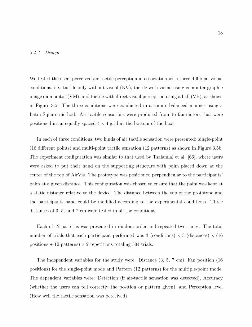
Figure 4.4: Interaction for fMRI-Compatible air-flow-based system, (a) open interaction tolift the ball by allowing air-flow, (b) close interaction to put the ball down by stopping air-flow, and (c) slide interaction for precise control of ball position by controlling the amountof air-flow.
motor generating air-flow through the transparent tube to 3D the printed hand-nozzle device
(Figure 4.4) which is held by the user. The hand-nozzle device was developed using a uPrint
SE 3D printer with ivory color ABSplus material.
The strength of the air-tactile feedback is correlated with the strength of air-flow that is
generated by the fan-motor. Furthermore, in Figure 4.4, position control of the ball can be
done in two different interactions, which are an on-off (open-close) interaction and a sliding
interaction. Open-close interaction provides a digital-like control, while the slide interaction
provide an analog-like control behavior.
Despite its simple setup, this system allows both soft tactile feedback (with just-noticeable
differences (JND) in air flow pressure) while concurrently recording user behavior when
precisely controlling the ball position, which normally could not be achieved with an optical-
fiber-based system. By utilizing data recorded by a flow-sensor, the interaction enabled by
this system can not only control the ball position (as shown in Figure 4.2), but also can be
used to provide a single-button-like response or an analog slider response (Figure 4.4).

32
Figure 4.5: Pneumatic and circuitry diagram for general design of pneumatic-based fMRI-compatible devices.
4.4 Novel Air-Pressure-Based fMRI-Compatible Interface Devices
The main design consideration is that, all components that will be put inside fMRI need to
be non-ferromagnetic and/or contain no metal/electronic circuit. Thus we focus on utilizing
air only without additional component such as potentiometer or LED to our systems. In
addition, the device should be able to be operated while the participant is lying down. The
pneumatic-based systems that we explored in this work rely on changes in air pressure to
record user response information, to generate tactile sensation to users or to send scented
air to users inside fMRI scanner.
4.4.1 Design
In this work, we explored three designs to serve three different purposes. The first purpose is
to dynamically change air pressure to alter the physical form of air pockets while the sensor
continuously reads internal air pressure of the system to allows precise close-loop control.
The second purpose is to only sensing user input with pressure sensors, thus further simplify
the system. The third purpose is to deliver smell from fragrance chamber outside of fMRI

33
Figure 4.6: Pneumatic and circuitry diagram for delivering smell to users inside fMRI scan-ner.
room to users inside the fMRI room while air pressure sensor and solenoid control the air
flow to user to have a constant pressure.
Figure 4.5 shows the diagram for the first pneumatic design. This first design is for
general use which contains an air-pump as pressure source, two solenoid valves, a pressure
sensor, and an interaction object (e.g., air pocket or 3D printed air chamber). In the rest
state, both solenoids A and B are closed (no air in or out, both solenoids are normally closed).
If solenoid A is actuated and B is at rest, the pressure source (air pump) can increases air
pressure in the system. If solenoid B is actuated, the system is open, releasing air and thus
decreasing the air pressure inside the system.
The second design is for recording air pressure information only. This design is the
simplified version of the first design which consist only air pressure sensor and the interaction
object as shown inside minimum circuit part of Figure 4.5. Assuming that there is no air-
leakage in the system, this is useful to reduce the number of components in the system and
to increase the scalability of the pneumatic system (e.g., although in a normal setup, a four-
button variable sensing device would require four air pumps, eight solenoid valves, and four

34
(a) (b) (c) (d) (e)
Figure 4.7: Three basic air pocket/chamber for pneumatic system a four-button pneumaticdevice, (a) an air-pocket fabricated by plastic welding, (b) a soft button fabricated by 3Dprinter with flexible material, (c) a hand squeeze device built from off-the-shelf lens blowerand teflon tape, (d) a freshly printed four-button flexible pneumatic device with mesh sup-porting structures, (e) finished 3D printed four-button flexible pneumatic device
pressure sensors, in simplified design, the same device only require four pressure sensors to
be functional). This design is limited to interaction objects that can return to its original
shape after pressed or squeezed by users. Therefore, interaction object such as air pockets
that need to be inflated first before can be used as interaction device can not use this design.
The last design is for delivering smell to users inside fMRI is shown in Figure 4.6. By
modifying the design in Figure 4.5, we can use the same components to allow different
stimulation for the users. Air pressure sensor continuously reads internal air pressure of the
system, if the internal air pressure is lower than required threshold (air-flow that deliver
the smell is weak), solenoid valve is switched off and air-pump increases pressure for the
fragrance chamber. If the internal air pressure is higher than threshold (strong air-flow), the
solenoid is activated allowing the smell to be delivered to the user. By monitoring the air
pressure to be close to the threshold value, this system can maintain a stable flow of smell
to the user. It is to be noted that this application, if used for a long period of time the
fragrance particle will diffuse overtime and making the smell weaker.

35
4.4.2 Fabrication
We fabricated the pneumatic devices using plastic welding and two different 3D printers
(one for rigid material and one for flexible material). The fabrication process using plastic
welding is straightforward, affordable, and fast, but have low replicability. Fabricating using
3D printer takes a little bit longer time to design and print, but is very replicable when
printing multiple custom devices.
Fabricating by Plastic Welding
In a condition where 3D printing is not available, plastic welding offer a fast way to develop
a prototype for air-pocket used in pneumatic systems. We used plastic welding method to
develop a simple air pocket by heat pressure molding off-the-shelf 0.3 mm thick polyethylene
sheets (plastic) into a square and attaching a pneumatic tube on one end of the pocket.
Although this method is error prone (e.g., it is difficult to form an airtight pocket in single
try), it is one of the fastest and most cost cost-effective ways to fabricate a custom-sized
air-pocket. To ensure the air pocket was airtight, we used airtight tape (teflon tape) and
heated it with a heat gun to close any possible openings. Using this simple method, we
were able to increase the fabrication success rate of this method. The fabricated air pocket
can sustain internal air pressure of 4.5 PSI before breaking. One example of air-pocket that
developed by this method is shown in Figure 4.7a. This air pocket can be used as an on-off
button and also a pressure sensitive button.
Fabricating by 3D Printing
Although plastic welding can be used to fabricate air pockets, its choice of geometry and
shape is limited and difficult to reproduce the same result multiple times. Therefore, we
combined the air pocket that we fabricated using plastic welding with rigid 3D printed part
to improve variation of pneumatic device that we can develop.
In order to make the appearance of the air pocket more appealing, we 3D printed a

36
Figure 4.8: Complete Pneumatic System.
case for four air pockets (Figure 4.1d) using a uPrint SE printer with ivory color ABSplus
material. This allows the four air-pockets to work as a four-button pneumatic device. Using
the same 3D printer, we also 3D printed a handle for the joystick device (Figure 4.1c). Since
the 3D printed part is used only as container, we designed so that it does not have any over-
hanging geometry in order to reduce any support material in printing result. By avoiding
over-hanging geometry, the fabrication process will become faster because it eliminates the
need to remove supporting material and cleaning process.
For soft and flexible parts of the system, we used a FORM2 printer with flexible resin3,
to fabricate soft and elastic part of our system, for example a soft pneumatic button (Figure
4.7b). Although flexible resin from formLabs can not elongate as much as TangoPlus used
in [67], it has a higher tensile strength which allows the printed parts to be more robust
from breaking. Additionally, in this 3D printer there is no supporting material. In order
to print any overhanging geometry, FORM2 uses mesh like supporting structure to hold the
geometry (see Figure 4.7d). One feature of this 3D printer is that, it allows printing a hollow
geometry without any internal support structure. Therefore, there is no need to clean the
internal part of the printed result. However, naively printing hollow structure will result in
failure of the 3D printed structure. In order to print overhanging and/or hollow geometry,
3A more detailed information of this material can be found inhttp://formlabs.com/products/materials/flexible/

37
the geometric should be tilted/positioned in such a way (around 15 to 20o) that each layer
of the 3D printed structure can support the hollow part without any supporting structure.
4.4.3 Applications
In this section, we will illustrate some potential applications of fMRI-compatible pneumatic-
based interaction devices. Figure 4.8 shows the pneumatic system that we used for all of the
following application. The pneumatic system consist of an off-the-shelf MIS-2500-015G air
pressure sensor from Metrodyne with a pressure range of 15 PSI (68.95 mbar) [1] to monitor
the pressure levels, two 2-way solenoid valve (model EXA-C6-02C-3) to regulate the system
pressure.
Pedal Simulation
Figure 4.9 shows a pedal interface constructed from woods, PVC tubes, and two lens blower
which are the same items used for hand squeeze device shown in Figure 4.7c. With two
pressure sensitive input devices connected together, the pedal device can simulate interaction
for acceleration and brake in car simulation. The pedal can detect when the user accelerate
(a) (b)
Figure 4.9: (a) Pedal simulation device which consisted of acceleration and brake pedals, (b)Experimental setup inside MRI device.

38
or brake, or detect whether the user make a slow acceleration/brake or fast. Currently,
there is no pressure sensitive pedal device available commercially, thus this device open an
opportunity for brain researchers, to better investigate human behavior when driving, i.e.,
not only investigate whether user press acceleration or brake, but also investigate how strong
the user need to press the pedals, or when the user make a mistake, how much pressure the
user already applied to pedal before realizing the mistake.
Wearable Wrist Haptic Feedback
We develop two flexible pneumatic buttons (Figure 4.7b) and put them together to make a
wearable wrist haptic device. Since the buttons are made from flexible material, increasing
internal air pressure of the pneumatic system can elongate the button giving a soft pressure
feedback. This wearable haptic device can be used by brain researchers to study human
reaction to haptic feedback that generated by smartwatch on the wrist. Since normal smart-
watch can not be used inside fMRI environment, this pneumatic wearable haptic device is a
good alternative to reproduce smartwatch haptic feedback inside fMRI. Wearable wrist can
be expanded by using more pneumatic buttons.
4.4.4 Interviewing MRI researchers
In order to understand whether the prototype was useful for the researchers, we interviewed
four expert researchers who work closely with fMRI devices. We asked three questions:
Q1 Can the proposed device be used as a response device for fMRI research?
Q2 Is any possible new device needed by fMRI researchers?
Q3 Would any new fMRI study be possible if these devices were available?
The researchers responses to the device were generally good because the prototypes pro-
vided richer information compared to fiber optic response devices which can only provide

39
binary (on-off) information. They agreed that the prototype can be used as an alternative
cost-effective response device for their future work using the fMRI device.
For Q2 and Q3, two researchers answered that they need a joystick-like response device, as
the fiber-optic one is currently very costly. The other researcher answered that a balloon like
device that can detect two handed interaction as well as the pressure from each finger would
help build an understanding of human motor interaction. Another researcher responded that
if the pressure is linear to the deviation of the pressed surface of the device, it can be used
to detect head movement adjustment for fMRI research.
4.5 fMRI-compatibility evaluation
We conducted an experiment to evaluate the fMRI-compatibility of the pneumatic device. A
device needs to satisfy three characteristics to be called fMRI-compatible. First, it must be
safe to use and not do any harm to the users in any way. Second, the device should not affect
the scanned image of the fMRI. Third, the device must be able to work properly within a
high magnetic field while the fMRI is running [23, 78].
The prototypes were designed to be compact, soft and free from any para-magnetic
material so that they will not be affected by the magnetic field of fMRI. Even if the prototype
hits the users in an accident, it will not harm the users in anyway. In order to be used for
fMRI environment, a minimum of 7 meters in tube length is needed as the participant needs
to use the device from inside the fMRI room. Therefore we used tube with 10 meters length
to allow more movement.
The experiment was supervised by an fMRI researcher/expert. As shown in Figure 4.10,
we placed the pneumatic response device on the fMRI bed together with an fMRI phantom
(an object used to evaluate the fMRI device that responds similarly to how human tissue
and organs act) [56]. The fMRI has different scanning sequences for different purposes. We
used a sequence that used the whole frequency range of the fMRI device so that if the device
did not effect any of the readings, the device can be said to be fMRI-compatible with any
scanning sequence.

40
(a) (b)
Figure 4.10: Experiment in the fMRI room and result images. a) The pneumatic device wasput on the fMRI bed to be tested, b) a view of the pneumatic device while the fMRI wasrunning.
We conducted three types of MRI-compatibility tests, which are i) Structural image scan
comparison, ii) Noise image scanning sequences, and iii) Echo planar imaging test. These
three tests were conducted for three conditions. The first condition was scanning with the
phantom only, this was to provide the baseline scanned image of the fMRI that is not affected
by any device. The second condition was scanning with the phantom and the prototype in
the off condition. This was done to investigate whether the prototype material affected the
scanned image. The third condition was scanning with the phantom and the prototype in
the running condition. This condition was done to test whether the prototype had any effect
on the scanned image from the fMRI. All experiments were conducted using a 3T Siemens
scanner.
4.6 MRI-Compatibility Results
4.6.1 Structural image scan comparison
Structural image scan is a straight-forward test to investigate whether there is any noise or
disturbance in the scanned image. As can be seen in 4.11, the scanned images for all three
conditions are nearly identical without any visible noise. By visually investigate these three

41
(a) (b) (c)
Figure 4.11: Structural image scan result. (a) without the pneumatic device, (b) the pneu-matic device inside the fMRI scanner off condition, (c) the pneumatic device inside thefMRI scanner on condition.
images, we can suggest that the pneumatic response device does not give any artifact to the
structural image of MRI.
4.6.2 Noise image scanning sequences
The noise scanned images from the three conditions are shown in Figure 4.12. One criteria
to define that the scanned image is free from disturbance is that the image should show
random noise. If there was any disturbance in the scanning process, the image should show
a white line (vertical/horizontal) on the image. During scanning in the third condition, we
also tested whether the scanning process affected the performance of the pneumatic response
device by monitoring the pressure sensor reading. We found that during the scanning process
the fMRI did not affect the pressure sensor reading (i.e., the sensor reading worked properly).
Based on the resulting images and the sensor readings, the fMRI researcher concluded that
the pneumatic response device has no effect on the scanned images and that it was fMRI-
compatible.
42
(a) (b) (c)
Figure 4.12: Noise image scanning sequences result. (a) without the pneumatic device, (b)the pneumatic device inside the fMRI scanner off condition, (c) the pneumatic device insidethe fMRI scanner on condition.
4.6.3 Echo planar imaging test
Compared to the other two test, EPI test is meant to measure the difference and loss of
Signal to noise ratio (SNR) on different scanning conditions. Thirty-four axial slices were
acquired for echo-planar imaging (EPI) with TR/TE value of 2000/30, FOV = 24cm, flip
size = 80, acquisition matrix size of 96x96, and voxel size of 3x3x3mm.
Additionally, the image quality were measured using time-variant signal-to-noise ration
(tSNR), which is the ratio between temporal mean and the temporal standard deviation of a
time-series. The results confirmed that the pneumatic devce is fMRI compatible with tSNR
decreased by less than 2%. The system also proved to be able to used to obtain a clear brain
scan images with similar activation to hand device.

43
Figure 4.13: EPI scan result. (a) without the pneumatic device, (b) the pneumatic deviceinside the fMRI scanner off condition, (c) the pneumatic device inside the fMRI scanner oncondition.
Figure 4.14: tSNR results. (a) without the pneumatic device, (b) the pneumatic deviceinside the fMRI scanner off condition, (c) the pneumatic device inside the fMRI scanner oncondition.

44
Chapter 5
AIR-BASED GAME INTERACTIONS
5.1 Introduction
Playing computer games is an enjoyable activity that is loved by many people. One inte-
gral game component that contributes to great player experiences is game input devices.
Keyboard and gamepad are two most commonly used input devices in video games.
However, the traditional input paradigm only supports binary and directional input and
thus, interaction bandwidth can be limited. This paper explores a novel parameter, i.e.,
air pressure, for game input. Air pressure supports continuous value, as opposed to binary
input in keyboard or gamepad. This continuous value is particularly intuitive in games where
there is a range of possible values, e.g., hitting a drum with different forces produces different
sound. To explore the feasibility, we developed AirDevice, a device that supports air pressure
input.
We explore the usefulness of AirDevice for game interaction in two custom-made games.
Our comparison with keyboard and gamepad found that AirDevice outperformed other de-
vices in immersion and fun, was well-accepted by participants, and can achieve equal perfor-
mance after five trials of training. This suggests that air pressure can serve as a promising
input for game interaction and can provide new forms of play. We conclude by discussing
future directions and possibilities of air-based game interaction, and the possibility to extend
it for exergames or health games alike.
Our contributions are threefold:
1. We propose a novel input device for games called AirDevice that supports air pressure
input.

45
2. We demonstrate how air pressure can be utilized in games by developing two custom-
made games and by showing how the act of squeezing can add a new dimension of play
to games.
3. We discuss future challenges and opportunities of air-based game interaction.
5.2 Related Work
Our work is related to two areas: game interaction and air-based interaction.
5.2.1 Game Interaction
Gamepad and keyboard (+ mouse) are two most commonly used input devices in video
games. Apart from these devices, there are abundant efforts from researchers to provide
new ways to interact with games such as the use of gaze [57], body movements [5], and
physiological signals [48] such as facial input [37] or heart rate [49]. One most recent devel-
opment is the idea of using brain-computer interfaces (BCI) through electro-encepalogram
(EEG) signals to control gaming [70]. Similar to these efforts, this work aims to expand the
interaction bandwidth of video games and proposes AirDevice that utilizes air pressure as
a new form of game interaction.
5.2.2 Air-based Interaction
The idea of using air for interaction has been used in the area of haptic stimulation. For
example, researchers have employed mid-air feedback for virtual reality applications [61].
Hachisu and Fukumoto [20] leverage the property of air suction for a haptic interface. There
also work on using the freeform quality of air to develop shape-changing interfaces [14, 76].
In sum, air has many good qualities for interaction which has not been explored in the games
domain. These works focused on providing feedback/output, little study have investigated
the use of air for input interaction, especially for game interaction. This work aims to fill
the gap.

46
Figure 5.1: Complete system of AirDevice.
5.3 Development of Air-Based Interface
The goal of AirDevice prototype is to develop a game input device that is able to provide
continuous data input. To achieve continuous data input, an off-the-shelf squeeze ball was
chosen. The squeeze ball was chosen because it has a form factor that can fit comfortably
to user hand and easy to provide push and squeeze interactions. Given that there is no
leak in the AirDevice system, push and squeeze interaction increases internal air-pressure of
AirDevice, and release interaction will return the internal air-pressure to its initial pressure
level. Additionally, the material of the squeeze ball is soft and rubber-like, enabling the
Figure 5.2: Diagrams of AirDevice, (a) electronic diagram of AirDevice, (b) pneumaticconnection of AirDevice.

47
ball to return to its initial form after squeezed and released, thus eliminating the need of
air-pump to continuously giving air in order to inflate the ball to its original shape.
5.3.1 Hardware Components
AirDevice (Figure 5.1) consists of an air-pressure sensor (MIS-2500-015G [1]), one three-
way solenoid valve (S070 series), a micro air-pump as air pressure source, and a hand-sized
ball-shaped soft container (Figure 5.3c) as the interaction device. Figure 5.2b shows the
pneumatic connection of all of the AirDevice components. All electronic components such
as air-pump, air-pressure sensor, and solenoid are electronically connected to (see Figure
5.2a) and controlled by an Arduino Micro (ATmega32U4). Arduino Micro has a small form-
factor and can work as generic keyboard and mouse without additional driver thus it is
convenient to be used for developing input devices. Air-pressure sensor is connected through
analog pin. Since the Arduino maximum current output for each pin is 40mA and power
requirement for air-pump and solenoid are higher, both components are connected through
digital pin with additional NPN transistor and a diode in order to control the high current
load.
5.3.2 Working Principle
In general, Airduino read the internal air-pressure information from the sensors continuously.
Changes in the internal air-pressure of AirDevice can be utilized for input interaction. There
are two way to use the air-pressure information, first, use the raw pressure data directly for
a continuous input, second, by defining pressure threshold, the system can be manipulated
to behave a certain way if a certain pressure level is achieved.
For the solenoid, in off condition, nozzle 1 and 2 of the three-way solenoid is connected
but not with nozzle 3, thus allowing air-pump (if powered on) to increase the internal air-
pressure of AirDevice. Conversely in on condition, the nozzle 1 of the three-way solenoid is
disconnected from nozzle 2 and connected to nozzle 3 (which is connected to environment),
thus allowing the air to escape reducing internal air-pressure of AirDevice. By increasing

48
Figure 5.3: a) Keyboard, b) Gamepad, c) AirDevice.
and decreasing the internal air-pressure, these two conditions can be utilized to regulate the
internal air-pressure of AirDevice.
5.4 User Study
We are interested in evaluating the effectiveness of AirDevice as a game input device. We
are also concerned about whether the participants’ preference affects the immersion level.
We compared immersion and usefulness level of each participant on three different input
devices (keyboard, gamepad, AirDevice) for playing two specific games. We also recorded
participants’ performance to investigate whether devices affect the performance.
Figure 5.4: Interface of the simple games; (a) flappy bird (copter) like game, (b) two-linerhythm game.

49
5.4.1 Game Selection
Figure 5.4 shows two simple games based on popular commercial video games, chopter/
flappy bird (Game 1) and rhythm/guitar hero (Game 2), which were developed to demon-
strate the capability of AirDevice as a game input device. Both games were chosen because
of their simple task and interaction method, also they were able to be played well using both
keyboard and gamepad. Thus, these games were good choices to evaluate the usefulness of
AirDevice as a game input device.
Game 1 requires participants to avoid the yellow obstacle by squeezing the AirDevice to
move the red-square up and release to move the red-square down. Interaction is the same
for keyboard and gamepad (push a button to move the red-square up and release to move it
down).
Game 2 requires participants to squeeze AirDevice with appropriate pressure levels. The
game recognizes two pressure levels (weak and strong). In the game, participants will be
presented with two types of circle as the target. Figure 5.4b shows the interaction for Game
2, when red circle arrives in a target area, the participants are required to squeeze with strong
pressure, likewise, the green circle for weak pressure. Since keyboard and most gamepads
are unable to accommodate pressure sensitive input, participants need to press four buttons
for left red, right red, left green, and right green circles.
For game 1, we recorded time elapse from game start until the red square hit the yellow
obstacle or reach time limit (60 seconds) as the participants performance. For Game 2, we
recorded the number of targets missed by the participant and divided it by a total number
of targets as the error rate. These performance parameters were recorded in the background
and did not show to the participants.
5.4.2 Participants and Apparatus
Twelve participants (6 females, M = 28 years, SD = 3.72) were recruited. Two participants
play video games for five to ten hours a month while the rest play less than two hours a

50
Figure 5.5: Experimental setup; (a) playing game using keyboard, (b) playing game usingAirDevice.
month. All participants have experience using keyboard and gamepad for playing games.
Experiment was conducted using a notebook PC with 64-bit Windows 10, Intel i7-
4710MQ processor, and 32 GB RAM. Participant used three input devices shown in Figure
5.3 to play both games.
5.4.3 Design
The experimental manipulation was Device (keyboard, gamepad, or AirDevice). The
participant’s preference for a particular input device was a pseudo-independent variable
(Preference). The dependent variables were immersion which was measured using the IEQ
(Immersive Experiment Questionnaire) [33], a 31 items questionnaire with five-point Likert
scale items, USE (Usefulness, Satisfaction, and Ease of use) questionnaire [40], a 30 items
questionnaire with five-point Likert scale items, and player performance parameters (scores
and error rates).

51
The IEQ can provide an overall measure of immersion as well as five factor of immersion,
which are cognitive involvement, emotional involvement, real world dissociation, challenge,
and control. We hypothesized that playing the game using AirDevice would achieve higher
immersion rating compared to playing using keyboard or gamepad. The USE questionnaire
provides a measure of usefulness, ease of use, ease of learn, and satisfaction. We hypoth-
esized that AirDevice would achieve at least equal or better usability rating compared to
keyboard and/or gamepad as a game input device. We measured player performance across
five repetitions. We hypothesized that AirDevice can reach similar performance as other
devices within these repetitions. Specifically, we seek to understand how fast can users learn
to use AirSqueenze.
5.4.4 Procedure
Participants were first informed about the objective and procedure of the study, and how to
play both games with each device. Participants were allowed to familiarize with the control
of all three devices. After that, participants were asked to play the games in six conditions
(2 games x 3 devices) as shown in Figure 5.5 in counter-balanced order using Latin square.
Each game was limited to one minute and repeated five times, resulting in approximately 30
minutes excluding rest time. Participants were not informed that their performance would
be recorded, to ensure participants to focus on the device and the game without worrying
about score or competition. Participants were asked and allowed to take a rest whenever they
feel tired. After all of the conditions were done, participants were required to complete the
IEQ and the USE questionnaire and open-ended questions regarding AirDevice, including
their preference of device for playing the games. All procedures took around 1.5 hours.
5.5 Results and Analysis
We investigated immersion, usefulness, and user performance for different game input de-
vices. All data conformed to two requirements for parametric evaluation namely, normal
distribution using the Kolmogorov-Smirnov test and equality of error variance using Levene’s

52
test. For the ANOVAs, we tested sphericity using Mauchly’s test and used a Greenhouse-
Geisser adjustment when the Mauchly’s test was significant; this adjustment can result in
fractional degrees of freedom.
5.5.1 IEQ
Table 5.1 shows results for each IEQ components (total immersion, cognitive involvement,
emotional involvement, real world dissociation, challenge, and control). The results show that
the participants achieve higher total immersion when they play with AirDevice (M = 97.61,
SD = 12.98) regardless of their preference compared to keyboard (M = 90.97, SD = 10.11)
and gamepad (M = 94.46, SD = 6.49). The results also shows that participants who prefer
to use AirDevice (M = 102.47, SD = 4.39) achieve higher total immersion regardless of the
Device used for playing the games, compared to participants who prefer keyboard (M =84.91, SD = 4.54) or prefer gamepad (M = 95.67, SD = 4.34).
We conducted a two-way repeated measures ANOVA with IEQ parameters as the depen-
dent variables: Device (3 levels, within-subjects) × Preference (3 levels, between-subjects).
The result showed that there was main effect on Device (F10,76 = 2.466, p = 0.013, η2p = 0.245,
Table 5.1: Total immersion and its components when playing using Keyboard(K),Gamepad(G), and AirDevice(A).
Play with K Play with G Play with A
Prefer K Prefer G Prefer A Prefer K Prefer G Prefer A Prefer K Prefer G Prefer A
M SD M SD M SD M SD M SD M SD M SD M SD M SD
TI 98.8 6.30 79.6 21.72 94.5 21.45 95.1 4.67 87.7 20.82 100.6 17.42 93.1 12.87 87.5 13.44 112.3 12.68
Cog.I 33.6 1.52 26.4 6.78 29.4 5.97 31.4 2.88 29.6 5.22 32.0 6.06 31.2 3.56 29.2 3.83 35.7 3.86
Emo.I 17.6 4.51 13.6 5.61 16.3 5.02 16.3 3.03 14.4 6.71 17.6 3.91 16.1 5.82 16.2 3.97 21.2 4.40
RWD 21.4 1.82 17.1 5.78 21.9 5.82 22.2 1.92 19.0 5.63 23.2 4.57 20.6 2.67 18.7 6.13 25.4 4.01
Cha. 9.8 1.92 8.0 2.06 10.6 2.37 9.6 2.07 8.4 2.55 9.9 2.33 9.8 1.64 9.1 2.03 10.9 1.91
Con. 16.4 0.89 14.4 4.82 16.4 5.17 15.6 2.51 16.2 4.06 17.9 4.18 15.4 3.13 14.3 2.45 19.1 3.25
Total Immersion (TI), Cognitive Involvement (Cog.I), Emotional Involvement (Emo.I), Real World Displacement (RWD),
Challenge (Cha.), and Control (Con.)

53
Table 5.2: Mean scores of USE components
Keyboard Gamepad AirDevice ANOVA
M SD M SD M SD F η2p
Usefulness 2.65 0.21 3.27 0.08 3.34 0.16 6.348∗∗ 0.366
Ease of Use 3.30 0.25 3.93 0.18 4.04 0.18 5.499∗ 0.333
Ease of Learn 3.19 0.26 3.67 0.24 3.98 0.23 6.359∗∗ 0.366
Satisfaction 2.62 0.31 3.35 0.18 3.80 0.19 8.152∗∗ 0.426
∗p < 0 .05 ,∗ ∗ p < 0 .01
Wilks λ = 0.570). However, there was no main effect on Preference, while the interaction
effects were marginal (F20,127 = 1.548, p = 0.076, η2p = 0.166, Wilks λ = 0.485). In terms of im-
mersion components, main effect ofDevice was found for cognitive involvement (F2,42 = 6.213,
p = 0.004, η2p = 0.228) and total immersion (F4,42 = 3.094, p < 0.05, η2p = 0.228). Also there
was interaction effect of Device and Preference on cognitive involvement (F4,42 = 3.094,
p < 0.05, η2p = 0.228). There was no main effect nor interaction effects for emotional involve-
ment, real world dissociation, challenge, and control components of immersion. Post-hoc
pairwise comparison using Bonferroni’s test shows that significantly different results were
found between keyboard and AirDevice for cognitive involvement (p < 0.05) and between
gamepad and AirDevice for the total immersion (p < 0.05).
These post-hoc results suggested that playing using AirDevice can improve users’ immer-
sion level significantly compared to the gamepad. Although the difference between AirDevice
and keyboard was not significant, the result was marginal.
5.5.2 USE questionnaire
Table 5.2 shows participants’ ratings regarding the interaction devices’ usefulness, ease of use,
ease of learn, and satisfaction. Overall, the results showed that mean values for AirDevice
was higher than keyboard and gamepad in all components of USE.
A one-way ANOVA showed that there were significant difference on which device to use

54
for playing the games on the combined components of USE (F (8,38) = 2.200, p < 0.05,
η2p = 0.317, Wilks’ λ = 0.467). Significant difference also found for Usefulness, (F (2,22 =6.348, p < 0.01, η2p = 0.366), Ease of Use (F (2,22) = 5.499, p = 0.012, η2p = 0.333), Ease of
Learn (F (2,22) = 6.359, p < 0.01, η2p = 0.366), and Satisfaction (F (2,22) = 8.152, p = 0.002,
η2p = 0.426). Post-hoc analysis using Bonferroni’s test showed that there were significant
differences between keyboard and gamepad for Usefulness (p < 0.05), between keyboard and
AirDevice for Ease of Learn (p < 0.05), between keyboard and gamepad for Satisfaction
(p < 0.05), and between keyboard and AirDevice for Satisfaction (p < 0.05).
These results revealed that the value was relative to the usefulness of the devices for
the specific games, not for general use or games. The results suggested that AirDevice was
easier to learn to use and provide higher user satisfaction when used for playing the games
compared to the keyboard. Nevertheless, it is important to note that this result applies only
to our games or alike but not the general games.
5.5.3 Player Performance
Figure 5.6 shows participants’ score for Game 1 and error rate for Game 2 for five repetitions
while using keyboard, gamepad, and AirDevice. Two-way repeated measures ANOVAs were
Figure 5.6: Performance parameter for repetition 1 to 5, mean score (a), error rate (b).

55
run for game 1 score and game 2 error rate as dependent variables, and with Device (3 levels,
within-subject) × Repetition (5 levels, within subject) as independent variables.
The ANOVA result for game 1 showed that there were main effect of Device (F (2,22) =5.666, p = 0.01, η2p = 0.340) and Repetition (F (2,22) = 5.809, p = 0.001, η2p = 0.346) to the
score, however there was no interaction effect found. Post-hoc pairwise comparison revealed
that there were significant difference between gamepad and AirDevice (p < 0.005), repetition
1 and 4 (p < 0.05), repetition 1 and 5 (p = 0.01), repetition 2 and 5 (p < 0.05), repetition 3
and 4 (p < 0.05), and between repetition 3 and 5 (p < 0.05). These results suggested that
participant’s learning curve for keyboard and AirDevice were same, and participants can
achieve similar performance for all Device after the fourth repetition, thus four repetitions
was adequate for participants to learn how to use AirDevice to achieve similar performance
with gamepad interface.
For Game 2, ANOVA showed that there was main effect on Device only (F (2,22) =19.354, p < 0.001, η2p = 0.366). This suggested that the error rate was highly impacted by the
device difference. Pair-wise comparison with Bonferroni’s test suggested that both gamepad
(p < 0.005) and AirDevice (p < 0.001) have significantly lower error rate compared to key-
board. This implies that playing game 2 using AirDevice can achieve similar performance
as playing the game using gamepad.
5.6 Discussion and Future Work
Our study confirmed that although preferences has an effect on user immersion, playing
games using AirSqueeze achieves higher levels of immersion and USE scores compared to
keyboard and gamepad. We also confirmed that four repetitions are adequate to learn how to
play games using AirSqueeze to achieve scores on par with gamepad. These results suggest
that air-pressure can be utilized as a game input device that can promote deeper immersion
when used with certain games.
Currently, AirSqueeze is connected to PC through a cable and has limited space for
movement. We can add greater freedom by applying wireless connections to AirSqueeze

56
instead of cable connections. AirSqueeze can also be used to further expand current gamepad
devices by redesigning the shape of AirSqueeze so it can be attached to the back of a
gamepad as an add-on device to enable squeezing interactions in gamepads and other game
input devices.

57
Chapter 6
GENERAL CONCLUSION AND FUTURE DIRECTIONS
6.1 Summary of Contributions
This dissertation presents three studies which focus on leveraging the use of air for designing
and developing air-based devices for interactions, and understanding interaction between
user and the air-based devices.
Study 1 concerned with the capability of air-based interaction devices to concurrently
providing multiple feedbacks for multimodal interactions. In this study, we developed a
prototype that is able to generate physical visual feedback as well as non-contact tactile
feedback in a single device. We proposed a straight-forward method to allows both feedbacks
to be generated simultaneously. The developed prototype achieved desirable results both in
term of device performances and user subjective assessments.
In Study 2, we proposed a specialized use case of air-based device where specific ca-
pabilities of air-based device that is able to not only provide multiple feedbacks but also
able to receive and record interaction information. We proposed novel air-based devices
that leverage the use of air-flow and air-pressure that are compatible to use inside MRI,
an environment with strong magnetic field and high magnetic interferences. We confirmed
that our proposed designs and prototypes are promising approach to further expands human
interaction research through a brain study using fMRI.
From Study 1 and Study 2, we observed that air has a lot of potential as a medium for
designing and developing interaction devices. In this dissertation we would like to add one
more parameter for the design of the air-based interaction devices, which is engagement. In
Study 3, we further improve the design of air-based device to be engaging, thus allowing
users to enjoy using the air-based device compared to conventional interaction devices. We

58
confirmed that user performance and satisfaction is higher for game interaction with air-based
devices. We also confirmed that, although users were able to familiarize themselves with air-
based devices very fast (within 2-3 trials). Based on these results, we discussed several design
guidelines to further improving the air-based device for an engaging interaction devices.
The outcome of this dissertation are:
1. An understanding of air properties for designing input interactions and haptic feed-
backs.
2. Several new air-based interaction devices.
3. Practical guidelines for interaction device design for multi-modal, MRI, and game
interactions.
In summary, this dissertation contributes to the field of interaction technology. The con-
clusion drawn and methodologies proposed will benefit future research studies that explore
the use of air-properties for interaction devices, and also future brain researches that utilize
air-based devices.
6.2 Future Research Direction
Throughout the project, the main design insight we have achieved is that instead of devel-
oping interaction devices only, it is important to identify one specific application that can
really leverage the advantages of the prototype. We come into conclusion that air-based
devices have a huge advantages and potential for fMRI-compatible response devices. Thus,
in the future we will conduct research studies on further investigating and developing various
response devices that are needed by brain researchers and MRI researchers. By doing so, we
believe, the MRI-compatible air-based device can expand the possible research direction in
the field of brain study that are previously very limited.

59
BIBLIOGRAPHY
[1] (2012). MIS-2500 series, Integrated Pressure Sensor. Metrodyne Microsystem Corp. Rev.
1.2.
[2] Alexander, J., Marshall, M. T., and Subramanian, S. (2011). Adding haptic feedback to
mobile tv. In CHI ’11 Extended Abstracts on Human Factors in Computing Systems, CHI
EA ’11, pages 1975–1980. ACM.
[3] Alrøe, T., Grann, J., Gronvall, E., Petersen, M. G., and Rasmussen, J. L. (2012). Aerial
tunes: Exploring interaction qualities of mid-air displays. In Proceedings of the 7th Nordic
Conference on Human-Computer Interaction: Making Sense Through Design, NordiCHI
’12, pages 514–523. ACM.
[4] Amaro, E. and Barker, G. J. (2006). Study design in fmri: basic principles. Brain and
cognition, 60(3):220–232.
[5] Bianchi-Berthouze, N., Kim, W. W., and Patel, D. (2007). Does body movement engage
you more in digital game play? and why? In International Conference on Affective
Computing and Intelligent Interaction, pages 102–113. Springer.
[6] Bier, E. A., Stone, M. C., Pier, K., Buxton, W., and DeRose, T. D. (1993). Toolglass
and magic lenses: the see-through interface. In Proceedings of the 20th annual conference
on Computer graphics and interactive techniques, pages 73–80. ACM.
[7] Carter, T., Seah, S. A., Long, B., Drinkwater, B., and Subramanian, S. (2013). Ultrahap-
tics: Multi-point mid-air haptic feedback for touch surfaces. In Proceedings of the Annual
ACM Symposium on User Interface Software and Technology, pages 505–514. ACM.

60
[8] Chen, P.-S. D., Lambert, A. D., and Guidry, K. R. (2010). Engaging online learners:
The impact of web-based learning technology on college student engagement. Computers
& Education, 54(4):1222–1232.
[9] Ciglar, M. (2010). An ultrasound based instrument generating audible and tactile sound.
In Proc. of NIME 2010, pages 19–22.
[10] Corporation, C. (2015). Lumina.
[11] Designs, C. (2016). Current designs.
[12] Falk, J., Ljungstrand, P., Bjork, S., and Hansson, R. (2001). Pirates: proximity-
triggered interaction in a multi-player game. In CHI’01 extended abstracts on Human
factors in computing systems, pages 119–120. ACM.
[13] Fischer, G. S., Iordachita, I., Csoma, C., Tokuda, J., DiMaio, S. P., Tempany, C. M.,
Hata, N., and Fichtinger, G. (2008). Mri-compatible pneumatic robot for transperineal
prostate needle placement. IEEE/ASME Trans. on Mechatronics, 13(3):295–305.
[14] Follmer, S., Leithinger, D., Olwal, A., Cheng, N., and Ishii, H. (2012). Jamming user
interfaces: Programmable particle stiffness and sensing for malleable and shape-changing
devices. In Proceedings of the Annual ACM Symposium on User Interface Software and
Technology, UIST ’12, pages 519–528. ACM.
[15] Follmer, S., Leithinger, D., Olwal, A., Hogge, A., and Ishii, H. (2013). inform: Dynamic
physical affordances and constraints through shape and object actuation. In Proceedings
of the Annual ACM Symposium on User Interface Software and Technology, UIST ’13,
pages 417–426. ACM.
[16] Frank Lopresti, E., Mihailidis, A., and Kirsch, N. (2004). Assistive technology for
cognitive rehabilitation: State of the art. Neuropsychological rehabilitation, 14(1-2):5–39.

61
[17] Gassert, R., Moser, R., Burdet, E., and Bleuler, H. (2006). Mri/fmri-compatible robotic
system with force feedback for interaction with human motion. IEEE ASME Trans. on
Mechatronics, 11(2):216.
[18] Golaszewski, S. M., Zschiegner, F., Siedentopf, C. M., Unterrainer, J., Sweeney, R. A.,
Eisner, W., Lechner-Steinleitner, S., Mottaghy, F. M., and Felber, S. (2002). A new
pneumatic vibrator for functional magnetic resonance imaging of the human sensorimotor
cortex. Neuroscience letters, 324(2):125–128.
[19] Gupta, S., Morris, D., Patel, S. N., and Tan, D. (2013). Airwave: Non-contact haptic
feedback using air vortex rings. In Proceedings of the 2013 ACM International Joint
Conference on Pervasive and Ubiquitous Computing, UbiComp ’13, pages 419–428. ACM.
[20] Hachisu, T. and Fukumoto, M. (2014). VacuumTouch : Attractive Force Feedback
Interface for Haptic Interactive Surface using Air Suction. In Proceedings of the Annual
ACM Conference on Human Factors in Computing Systems, CHI ’14, pages 411–420.
ACM.
[21] Hao, Y., Manor, B., Liu, J., Zhang, K., Chai, Y., Lipsitz, L., Peng, C.-K., Novak,
V., Wang, X., Zhang, J., et al. (2013). Novel mri-compatible tactile stimulator for cor-
tical mapping of foot sole pressure stimuli with fmri. Magnetic Resonance in Medicine,
69(4):1194–1199.
[22] Harrison, C. and Hudson, S. E. (2009). Providing dynamically changeable physical
buttons on a visual display. In Proceedings of the Annual ACM Conference on Human
Factors in Computing Systems, pages 299–308.
[23] Hollinger, A. (2008). Design of fmri-compatible electronic musical interfaces. Master’s
thesis, McGill University, Motreal, Canada.
[24] Hoshi, T. (2011). Development of aerial-input and aerial-tactile-feedback system. In
World Haptics Conference (WHC), 2011 IEEE, pages 569–573. IEEE.

62
[25] Hoshi, T. (2012). Handwriting transmission system using noncontact tactile display. In
IEEE Haptics Symposium (HAPTICS), pages 399–401. IEEE.
[26] Hoshi, T., Takahashi, M., Iwamoto, T., and Shinoda, H. (2010). Noncontact Tactile
Display Based on Radiation Pressure of Airborne Ultrasound. IEEE Transactions on
Haptics, 3(3):155–165.
[27] Hoshi, T., Takahashi, M., Nakatsuma, K., and Shinoda, H. (2009). Touchable hologra-
phy. In ACM SIGGRAPH 2009 Emerging Technologies, SIGGRAPH ’09, pages 23:1–23:1,
New York, NY, USA. ACM.
[28] Huettel, S. A., Song, A. W., and McCarthy, G. (2004). Functional magnetic resonance
imaging, volume 1. Sinauer Associates Sunderland.
[29] Ishii, H. (2008). The tangible user interface and its evolution. Communications of the
ACM, 51(6):32–36.
[30] Iwamoto, T., Tatezono, M., and Shinoda, H. (2008). Non-contact Method for Pro-
ducing Tactile Sensation Using Airborne Ultrasound. In Ferre, M., editor, EuroHaptics,
EuroHaptics ’08, pages 504–513, Berlin, Heidelberg. Springer-Verlag.
[31] Jaimes, A. and Sebe, N. (2007). Multimodal human–computer interaction: A survey.
Computer vision and image understanding, 108(1):116–134.
[32] Jarrahi, B., Wanek, J., Mehnert, U., and Kollias, S. (2013). An fmri-compatible multi-
configurable handheld response system using an intensity-modulated fiber-optic sensor. In
IEEE ICEMBC, pages 6349–6352. IEEE.
[33] Jennett, C., Cox, A. L., Cairns, P., Dhoparee, S., Epps, A., Tijs, T., and Walton,
A. (2008). Measuring and defining the experience of immersion in games. International
journal of human-computer studies, 66(9):641–661.

63
[34] Kearsley, G. and Shneiderman, B. (1998). Engagement theory: A framework for
technology-based teaching and learning. Educational technology, 38(5):20–23.
[35] Kim, S., Kim, H., Lee, B., Nam, T.-J., and Lee, W. (2008). Inflatable mouse: volume-
adjustable mouse with air-pressure-sensitive input and haptic feedback. In Proceedings of
the Annual ACM Conference on Human Factors in Computing Systems, pages 211–224.
ACM.
[36] Kulkarni, S. D., Fisher, C. J., Lefler, P., Desai, A., Chakravarthy, S., Pardyjak, E. R.,
Minor, M. A., and Hollerbach, J. M. (2015). A full body steerable wind display for a loco-
motion interface. IEEE transactions on visualization and computer graphics, 21(10):1146–
1159.
[37] Lankes, M., Riegler, S., Weiss, A., Mirlacher, T., Pirker, M., and Tscheligi, M. (2008).
Facial expressions as game input with different emotional feedback conditions. In Pro-
ceedings of the 2008 International Conference on Advances in Computer Entertainment
Technology, pages 253–256. ACM.
[38] Lee, B., Isenberg, P., Riche, N. H., and Carpendale, S. (2012). Beyond mouse and key-
board: Expanding design considerations for information visualization interactions. IEEE
Transactions on Visualization and Computer Graphics, 18(12):2689–2698.
[39] Lee, J., Post, R., and Ishii, H. (2011). Zeron: Mid-air tangible interaction enabled by
computer controlled magnetic levitation. In Proceedings of the Annual ACM Symposium
on User Interface Software and Technology, pages 327–336. ACM.
[40] Lund, A. M. (2001). Measuring usability with the use questionnaire. Usability interface,
8(2):3–6.
[41] Manresa, C., Varona, J., Mas, R., and Perales, F. J. (2005). Hand tracking and gesture
recognition for human-computer interaction. ELCVIA Electronic Letters on Computer
Vision and Image Analysis, 5(3):96–104.

64
[42] Marshall, M., Carter, T., Alexander, J., and Subramanian, S. (2012). Ultra-tangibles:
Creating movable tangible objects on interactive tables. In Proceedings of the Annual
ACM Conference on Human Factors in Computing Systems, CHI ’12, pages 2185–2188,
New York, NY, USA. ACM.
[43] Matsukura, H., Nihei, T., and Ishida, H. (2011). Multi-sensorial field display: Presenting
spatial distribution of airflow and odor. In Virtual Reality Conference (VR), 2011 IEEE,
pages 119–122.
[44] Meinhardt, J. and Muller, J. (2001). Motor response detection using fiber optics dur-
ing functional magnetic resonance imaging. Behavior Research Methods, Instruments, &
Computers, 33(4):556–558.
[45] Meyrowitz, N. and Van Dam, A. (1982). Interactive editing systems: Part i. ACM
Computing Surveys (CSUR), 14(3):321–352.
[46] Mosadegh, B., Polygerinos, P., Keplinger, C., Wennstedt, S., Shepherd, R. F., Gupta,
U., Shim, J., Bertoldi, K., Walsh, C. J., and Whitesides, G. M. (2014). Pneumatic networks
for soft robotics that actuate rapidly. Advanced Functional Materials, 24(15):2163–2170.
[47] Myers, B. A. (1998). A brief history of human-computer interaction technology. inter-
actions, 5(2):44–54.
[48] Nacke, L. E., Kalyn, M., Lough, C., and Mandryk, R. L. (2011). Biofeedback game
design: using direct and indirect physiological control to enhance game interaction. In
Proceedings of the Annual ACM Conference on Human Factors in Computing Systems,
pages 103–112. ACM.
[49] Nenonen, V., Lindblad, A., Hakkinen, V., Laitinen, T., Jouhtio, M., and Hamalainen,
P. (2007). Using heart rate to control an interactive game. In Proceedings of the Annual
ACM Conference on Human Factors in Computing Systems, pages 853–856. ACM.

65
[50] Nielsen, J. (1995). Multimedia and hypertext: The Internet and beyond. Morgan Kauf-
mann.
[51] Ochiai, Y., Hoshi, T., and Rekimoto, J. (2014). Pixie dust: Graphics generated by lev-
itated and animated objects in computational acoustic-potential field. ACM SIGGRAPH
2014, 33(4):85:1–85:13.
[52] Omirou, T., Marzo, A., Seah, S. A., and Subramanian, S. (2015). Levipath: Modular
acoustic levitation for 3d path visualisations. In Proceedings of the Annual ACM Con-
ference on Human Factors in Computing Systems, pages 309–312, New York, NY, USA.
ACM.
[53] Raffle, H., Tichenor, J., and Ishii, H. (2004). Super cilia skin: A textural interface.
Textile, 2(3):328–347.
[54] Rasmussen, M. K., Pedersen, E. W., Petersen, M. G., and Hornbæk, K. (2012). Shape-
changing interfaces: a review of the design space and open research questions. In Pro-
ceedings of the Annual ACM Conference on Human Factors in Computing Systems, pages
735–744. ACM.
[55] Reeves, L. M., Lai, J., Larson, J. A., Oviatt, S., Balaji, T., Buisine, S., Collings, P.,
Cohen, P., Kraal, B., Martin, J.-C., et al. (2004). Guidelines for multimodal user interface
design. Communications of the ACM, 47(1):57–59.
[56] Renvall, V. (2009). Functional magnetic resonance imaging reference phantom. Magnetic
Resonance Imaging, 27(5):701 – 708.
[57] San Agustin, J., Mateo, J. C., Hansen, J. P., and Villanueva, A. (2009). Evaluation of
the potential of gaze input for game interaction. PsychNology Journal, 7(2):213–236.
[58] Savage, V., Schmidt, R., Grossman, T., Fitzmaurice, G., and Hartmann, B. (2014). A
series of tubes: Adding interactivity to 3d prints using internal pipes. In Proceedings of

66
the Annual ACM Symposium on User Interface Software and Technology, UIST ’14, pages
3–12. ACM.
[59] Schneider, B., Jermann, P., Zufferey, G., and Dillenbourg, P. (2011). Benefits of a tan-
gible interface for collaborative learning and interaction. IEEE Transactions on Learning
Technologies, 4(3):222–232.
[60] Slyper, R. and Hodgins, J. (2012). Prototyping robot appearance, movement, and
interactions using flexible 3d printing and air pressure sensors. In RO-MAN, 2012 IEEE,
pages 6–11.
[61] Sodhi, R., Poupyrev, I., Glisson, M., and Israr, A. (2013). Aireal: Interactive tactile
experiences in free air. ACM SIGGRAPH 2013, 32(4):134:1–134:10.
[62] Sutherland, I. E. (1964). Sketch pad a man-machine graphical communication system.
In Proceedings of the SHARE design automation workshop, pages 6–329. ACM.
[63] Suzuki, Y. and Kobayashi, M. (2005). Air jet driven force feedback in virtual reality.
IEEE computer graphics and applications, 25(1):44–47.
[64] Suzuki, Y., Kobayashi, M., and Ishibashi, S. (2002). Design of force feedback utilizing
air pressure toward untethered human interface. In CHI ’02 Extended Abstracts on Human
Factors in Computing Systems, CHI EA ’02, pages 808–809. ACM.
[65] Tada, M. and Kanade, T. (2004). An mr-compatible optical force sensor for human
function modeling. In Medical Image Computing and Computer-Assisted Intervention–
MICCAI 2004, pages 129–136. Springer.
[66] Tsalamlal, M. Y. and Ouarti, N. (2013). Psychophysical study of air jet based tactile
stimulation. In IEEE World Haptics, pages 639–644.
[67] Vazquez, M., Brockmeyer, E., Desai, R., Harrison, C., and Hudson, S. E. (2015). 3d
printing pneumatic device controls with variable activation force capabilities. In Proceed-

67
ings of the Annual ACM Conference on Human Factors in Computing Systems, CHI ’15,
pages 1295–1304. ACM.
[68] Vega-Bermudez, F. and Johnson, K. O. (2001). Differences in Spatial Acuity Between
Digits. Neurology, 56(10):234–244.
[69] vom Lehn, D., Hindmarsh, J., Luff, P., and Heath, C. (2007). Engaging constable:
revealing art with new technology. In Proceedings of the Annual ACM Conference on
Human Factors in Computing Systems, pages 1485–1494. ACM.
[70] Wang, Q., Sourina, O., and Nguyen, M. K. (2010). Eeg-based” serious” games design
for medical applications. In Cyberworlds (cw), 2010 international conference on, pages
270–276. IEEE.
[71] Weiss, M., Wacharamanotham, C., Voelker, S., and Borchers, J. (2011). Fingerflux:
Near-surface haptic feedback on tabletops. In Proceedings of the Annual ACM Symposium
on User Interface Software and Technology, UIST ’11, pages 615–620, New York, NY,
USA. ACM.
[72] Wienbruch, C., Candia, V., Svensson, J., Kleiser, R., and Kollias, S. S. (2006). A
portable and low-cost fmri compatible pneumatic system for the investigation of the
somatosensensory system in clinical and research environments. Neuroscience letters,
398(3):183–188.
[73] Wilson, G., Carter, T., Subramanian, S., and Brewster, S. (2014). Perception of Ultra-
sonic Haptic Feedback on the Hand : Localisation and Apparent Motion. In Proceedings
of the Annual ACM Conference on Human Factors in Computing Systems, CHI ’14, pages
1133–1142. ACM.
[74] Wolf, M. J. (2008). The video game explosion: a history from PONG to Playstation and
beyond. ABC-CLIO.

68
[75] Woods, T. O. (2007). Standards for medical devices in mri: Present and future. Journal
of Magnetic Resonance Imaging, 26(5):1186–1189.
[76] Yao, L., Niiyama, R., Ou, J., Follmer, S., Della Silva, C., and Ishii, H. (2013). Pneui:
Pneumatically actuated soft composite materials for shape changing interfaces. In Pro-
ceedings of the Annual ACM Symposium on User Interface Software and Technology, UIST
’13, pages 13–22, New York, NY, USA. ACM.
[77] Yu, N., Hollnagel, C., Blickenstorfer, A., Kollias, S., and Riener, R. (2008). fmri-
compatible robotic interfaces with fluidic actuation. Robotics: Science and Systems IV,
Zurich, Switzerland, June, pages 25–28.
[78] Yu, N., Murr, W., Blickenstorfer, A., Kollias, S., and Riener, R. (2007). An fmri
compatible haptic interface with pneumatic actuation. In Rehabilitation Robotics, 2007.
ICORR 2007. IEEE 10th International Conference on, pages 714–720.