lan system k electrical - 洲/原厂维修手册/日产... · pdf filewith door mirror...
TRANSCRIPT
LAN-1
LAN SYSTEM
K ELECTRICAL
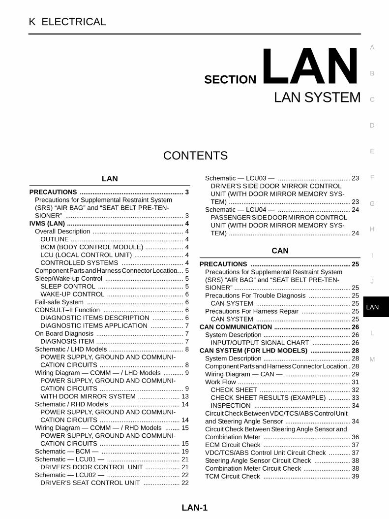
CONTENTS
C
D
E
F
G
H
I
J
L
M
SECTION
A
B
LAN
LAN SYSTEM
LAN
PRECAUTIONS .......................................................... 3Precautions for Supplemental Restraint System (SRS) “AIR BAG” and “SEAT BELT PRE-TEN-SIONER” .................................................................. 3
IVMS (LAN) ................................................................. 4Overall Description ................................................... 4
OUTLINE ............................................................... 4BCM (BODY CONTROL MODULE) ...................... 4LCU (LOCAL CONTROL UNIT) ............................ 4CONTROLLED SYSTEMS ................................... 4
Component Parts and Harness Connector Location ..... 5Sleep/Wake-up Control ............................................ 5
SLEEP CONTROL ................................................ 5WAKE-UP CONTROL ........................................... 6
Fail-safe System ...................................................... 6CONSULT–II Function ............................................. 6
DIAGNOSTIC ITEMS DESCRIPTION .................. 6DIAGNOSTIC ITEMS APPLICATION ................... 7
On Board Diagnosis ................................................. 7DIAGNOSIS ITEM ................................................. 7
Schematic / LHD Models .......................................... 8POWER SUPPLY, GROUND AND COMMUNI-CATION CIRCUITS ............................................... 8
Wiring Diagram — COMM — / LHD Models ............ 9POWER SUPPLY, GROUND AND COMMUNI-CATION CIRCUITS ............................................... 9WITH DOOR MIRROR SYSTEM ........................ 13
Schematic / RHD Models ....................................... 14POWER SUPPLY, GROUND AND COMMUNI-CATION CIRCUITS ............................................. 14
Wiring Diagram — COMM — / RHD Models ......... 15POWER SUPPLY, GROUND AND COMMUNI-CATION CIRCUITS ............................................. 15
Schematic — BCM — ............................................ 19Schematic — LCU01 — ......................................... 21
DRIVER'S DOOR CONTROL UNIT .................... 21Schematic — LCU02 — ......................................... 22
DRIVER'S SEAT CONTROL UNIT ..................... 22
Schematic — LCU03 — ......................................... 23DRIVER'S SIDE DOOR MIRROR CONTROL UNIT (WITH DOOR MIRROR MEMORY SYS-TEM) .................................................................... 23
Schematic — LCU04 — ......................................... 24PASSENGER SIDE DOOR MIRROR CONTROL UNIT (WITH DOOR MIRROR MEMORY SYS-TEM) .................................................................... 24
CAN
PRECAUTIONS ........................................................ 25Precautions for Supplemental Restraint System (SRS) “AIR BAG” and “SEAT BELT PRE-TEN-SIONER” ................................................................. 25Precautions For Trouble Diagnosis ........................ 25
CAN SYSTEM ..................................................... 25Precautions For Harness Repair ............................ 25
CAN SYSTEM ..................................................... 25CAN COMMUNICATION ........................................... 26
System Description ................................................. 26INPUT/OUTPUT SIGNAL CHART ...................... 26
CAN SYSTEM (FOR LHD MODELS) ....................... 28System Description ................................................. 28Component Parts and Harness Connector Location ... 28Wiring Diagram — CAN — ..................................... 29Work Flow ............................................................... 31
CHECK SHEET ................................................... 32CHECK SHEET RESULTS (EXAMPLE) ............. 33INSPECTION ...................................................... 34
Circuit Check Between VDC/TCS/ABS Control Unit and Steering Angle Sensor ..................................... 34Circuit Check Between Steering Angle Sensor and Combination Meter ................................................. 36ECM Circuit Check ................................................. 37VDC/TCS/ABS Control Unit Circuit Check ............. 37Steering Angle Sensor Circuit Check ..................... 38Combination Meter Circuit Check ........................... 38TCM Circuit Check ................................................. 39
LAN-2
CAN Communication Circuit Check ........................ 39Component Inspection ............................................ 44
ECM/TCM INTERNAL CIRCUIT INSPECTION ... 44CAN SYSTEM (FOR RHD MODELS) ....................... 45
System Description ................................................. 45Component Parts and Harness Connector Location ... 45Wiring Diagram — CAN — ..................................... 46Work Flow ............................................................... 48
CHECK SHEET ................................................... 49CHECK SHEET RESULTS (EXAMPLE) ............. 50INSPECTION ....................................................... 51
Circuit Check Between VDC/TCS/ABS Control Unit
and Steering Angle Sensor .....................................51Circuit Check Between Steering Angle Sensor and Combination Meter ..................................................52ECM Circuit Check ..................................................53VDC/TCS/ABS Control Unit Circuit Check ..............54Steering Angle Sensor Circuit Check ......................54Combination Meter Circuit Check ...........................55TCM Circuit Check ..................................................55CAN Communication Circuit Check ........................56Component Inspection ............................................59
ECM/TCM INTERNAL CIRCUIT INSPECTION ...59
PRECAUTIONS
LAN-3
[LAN]
C
D
E
F
G
H
I
J
L
M
A
B
LAN
[LAN]PRECAUTIONS PFP:00001
Precautions for Supplemental Restraint System (SRS) “AIR BAG” and “SEAT BELT PRE-TENSIONER” EKS001SS
The Supplemental Restraint System such as “AIR BAG” and “SEAT BELT PRE-TENSIONER”, used alongwith a front seat belt, helps to reduce the risk or severity of injury to the driver and front passenger for certaintypes of collision. Information necessary to service the system safely is included in the SRS and SB section ofthis Service Manual.WARNING: To avoid rendering the SRS inoperative, which could increase the risk of personal injury or death
in the event of a collision which would result in air bag inflation, all maintenance must be per-formed by an authorized NISSAN/INFINITI dealer.
Improper maintenance, including incorrect removal and installation of the SRS, can lead to per-sonal injury caused by unintentional activation of the system. For removal of Spiral Cable and AirBag Module, see the SRS section.
Do not use electrical test equipment on any circuit related to the SRS unless instructed to in thisService Manual. SRS wiring harnesses can be identified by yellow and/or orange harness connec-tors.
LAN-4
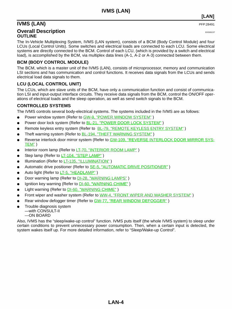
[LAN]IVMS (LAN)
IVMS (LAN) PFP:28491
Overall Description EKS001ST
OUTLINEThe In-Vehicle Multiplexing System, IVMS (LAN system), consists of a BCM (Body Control Module) and fourLCUs (Local Control Units). Some switches and electrical loads are connected to each LCU. Some electricalsystems are directly connected to the BCM. Control of each LCU, (which is provided by a switch and electricalload), is accomplished by the BCM, via multiplex data lines (A-1, A-2 or A-3) connected between them.
BCM (BODY CONTROL MODULE)The BCM, which is a master unit of the IVMS (LAN), consists of microprocessor, memory and communicationLSI sections and has communication and control functions. It receives data signals from the LCUs and sendselectrical load data signals to them.
LCU (LOCAL CONTROL UNIT)The LCUs, which are slave units of the BCM, have only a communication function and consist of communica-tion LSI and input-output interface circuits. They receive data signals from the BCM, control the ON/OFF oper-ations of electrical loads and the sleep operation, as well as send switch signals to the BCM.
CONTROLLED SYSTEMSThe IVMS controls several body-electrical systems. The systems included in the IVMS are as follows: Power window system (Refer to GW-9, "POWER WINDOW SYSTEM" ) Power door lock system (Refer to BL-21, "POWER DOOR LOCK SYSTEM" ) Remote keyless entry system (Refer to BL-79, "REMOTE KEYLESS ENTRY SYSTEM" ) Theft warning system (Refer to BL-194, "THEFT WARNING SYSTEM" ) Reverse interlock door mirror system (Refer to GW-109, "REVERSE INTERLOCK DOOR MIRROR SYS-
TEM" ) Interior room lamp (Refer to LT-70, "INTERIOR ROOM LAMP" ) Step lamp (Refer to LT-104, "STEP LAMP" ) Illumination (Refer to LT-135, "ILLUMINATION" ) Automatic drive positioner (Refer to SE-5, "AUTOMATIC DRIVE POSITIONER" ) Auto light (Refer to LT-5, "HEADLAMP" ) Door warning lamp (Refer to DI-28, "WARNING LAMPS" ) Ignition key warning (Refer to DI-60, "WARNING CHIME" ) Light warning (Refer to DI-60, "WARNING CHIME" ) Front wiper and washer system (Refer to WW-4, "FRONT WIPER AND WASHER SYSTEM" ) Rear window defogger timer (Refer to GW-77, "REAR WINDOW DEFOGGER" ) Trouble diagnosis system
—with CONSULT-II—ON BOARD
Also, IVMS has the “sleep/wake-up control” function. IVMS puts itself (the whole IVMS system) to sleep undercertain conditions to prevent unnecessary power consumption. Then, when a certain input is detected, thesystem wakes itself up. For more detailed information, refer to “Sleep/Wake-up Control”.
IVMS (LAN)
LAN-5
[LAN]
C
D
E
F
G
H
I
J
L
M
A
B
LAN
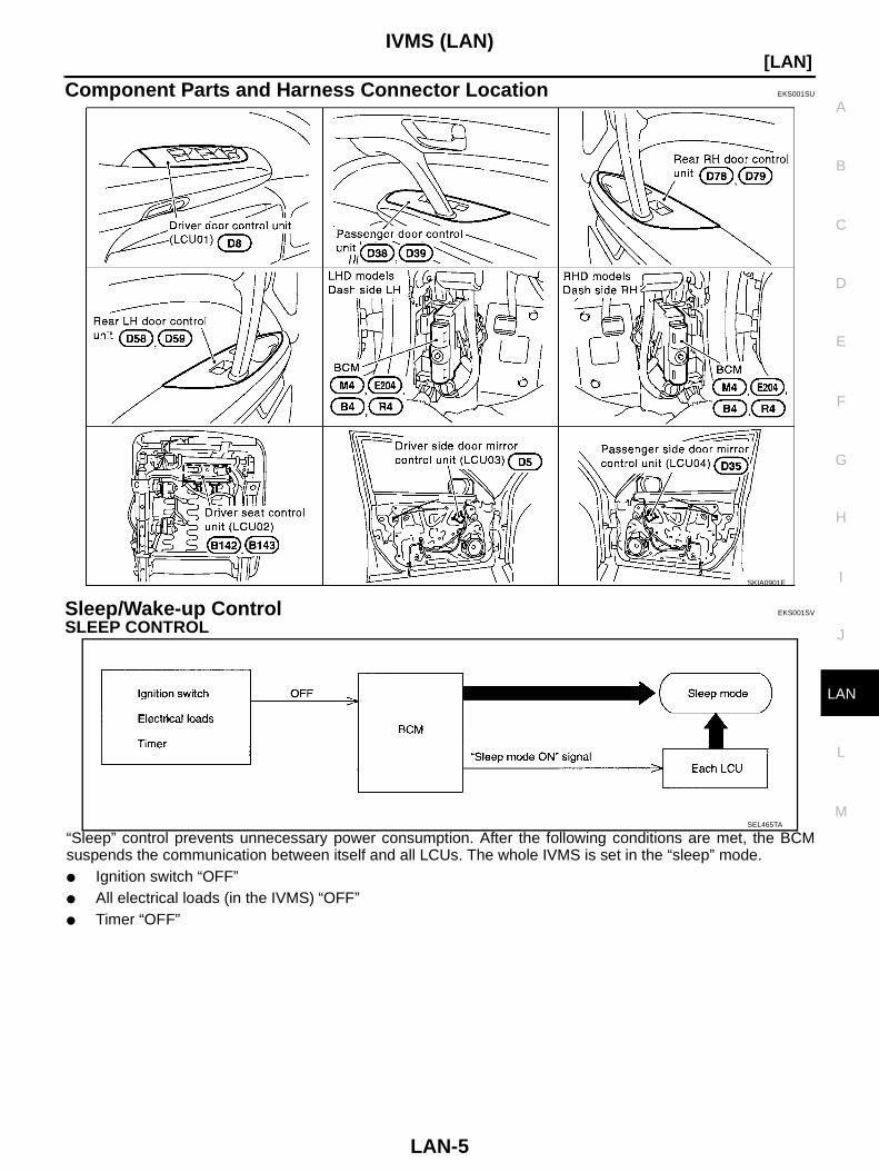
Component Parts and Harness Connector Location EKS001SU
Sleep/Wake-up Control EKS001SV
SLEEP CONTROL
“Sleep” control prevents unnecessary power consumption. After the following conditions are met, the BCMsuspends the communication between itself and all LCUs. The whole IVMS is set in the “sleep” mode. Ignition switch “OFF” All electrical loads (in the IVMS) “OFF” Timer “OFF”
SKIA0901E
SEL465TA
LAN-6
[LAN]IVMS (LAN)
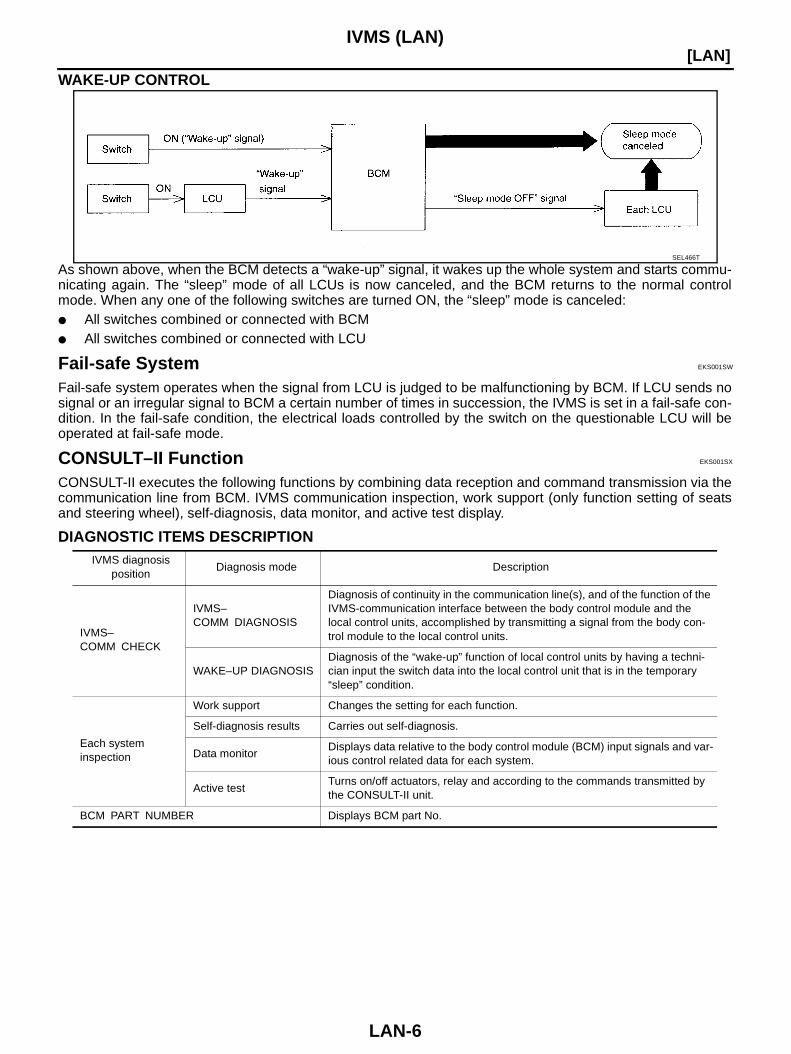
WAKE-UP CONTROL
As shown above, when the BCM detects a “wake-up” signal, it wakes up the whole system and starts commu-nicating again. The “sleep” mode of all LCUs is now canceled, and the BCM returns to the normal controlmode. When any one of the following switches are turned ON, the “sleep” mode is canceled: All switches combined or connected with BCM All switches combined or connected with LCU
Fail-safe System EKS001SW
Fail-safe system operates when the signal from LCU is judged to be malfunctioning by BCM. If LCU sends nosignal or an irregular signal to BCM a certain number of times in succession, the IVMS is set in a fail-safe con-dition. In the fail-safe condition, the electrical loads controlled by the switch on the questionable LCU will beoperated at fail-safe mode.
CONSULT–II Function EKS001SX
CONSULT-II executes the following functions by combining data reception and command transmission via thecommunication line from BCM. IVMS communication inspection, work support (only function setting of seatsand steering wheel), self-diagnosis, data monitor, and active test display.
DIAGNOSTIC ITEMS DESCRIPTION
SEL466T
IVMS diagnosis position
Diagnosis mode Description
IVMS–COMM CHECK
IVMS–COMM DIAGNOSIS
Diagnosis of continuity in the communication line(s), and of the function of the IVMS-communication interface between the body control module and the local control units, accomplished by transmitting a signal from the body con-trol module to the local control units.
WAKE–UP DIAGNOSISDiagnosis of the “wake-up” function of local control units by having a techni-cian input the switch data into the local control unit that is in the temporary “sleep” condition.
Each system inspection
Work support Changes the setting for each function.
Self-diagnosis results Carries out self-diagnosis.
Data monitorDisplays data relative to the body control module (BCM) input signals and var-ious control related data for each system.
Active testTurns on/off actuators, relay and according to the commands transmitted by the CONSULT-II unit.
BCM PART NUMBER Displays BCM part No.
IVMS (LAN)
LAN-7
[LAN]
C
D
E
F
G
H
I
J
L
M
A
B
LAN
DIAGNOSTIC ITEMS APPLICATION
X: ApplicableFor diagnostic item in each control system, read the CONSULT-ll Operation Manual.
On Board Diagnosis EKS001SY
ON BOARD DIAGNOSTIC RESULTS INDICATOR LAMP Front map lamps and step lamps (all seats) act as the indicators for the on board diagnosis.
DIAGNOSIS ITEM
Test item Diagnosed system
MODE
IVMS COMM
DIAGNO-SIS
WAKE-UP DIAGNO-
SIS
SELF DIAG-
NOSTIC RESULTS
DATA MONITOR
ACTIVE TEST
WORK SUPPORT
IVMS-COMM CHECK IVMS communica-tion and wake-up function
× ×
DOOR LOCKPower door lock sys-tem
× × ×
AUTO DRIVE POSI-TIONER
Automatic drive posi-tioner / Reverse inter-lock door mirror system
× × × ×
WIPERFront wiper and washer system
× × ×
REAR DEFOGGERRear window defog-ger
× ×
IGN KEY WARN ALM Warning chime × ×
LIGHT WARN ALM Warning chime × ×
THEFT WARNING SYS-TEM
Theft warning system × × ×
STEP LAMP Step lamps × ×
MULTI-REMOTE CONT SYS
Remote keyless entry system
× × ×
INTERIOR ILLUMINA-TION
Interior room lamp × × ×
SUNROOF RELAY Sunroof × ×
DOOR OPEN WARNING Warning chime × ×
AUTO LIGHT SYSTEM Headlamp × × ×
Diagnosis item Content
IVMS communication diagnosis Diagnosis any error or inability of communication between BCM and LCUs.
Switch monitor Monitoring conditions of switches connected to BCM, LCUs and door control units.
Power door lock system self-diagnosis Diagnose malfunctions in the each door lock actuator system.
Auto drive positioner self-diagnosisDiagnose malfunctions in the each motor and sensor in the electrical load parts of the driver power seat system (sliding, reclining, and lifter [front/rear]), of the steering wheel system (tilt, telescoping), and of door mirror.
LAN-8
[LAN]IVMS (LAN)
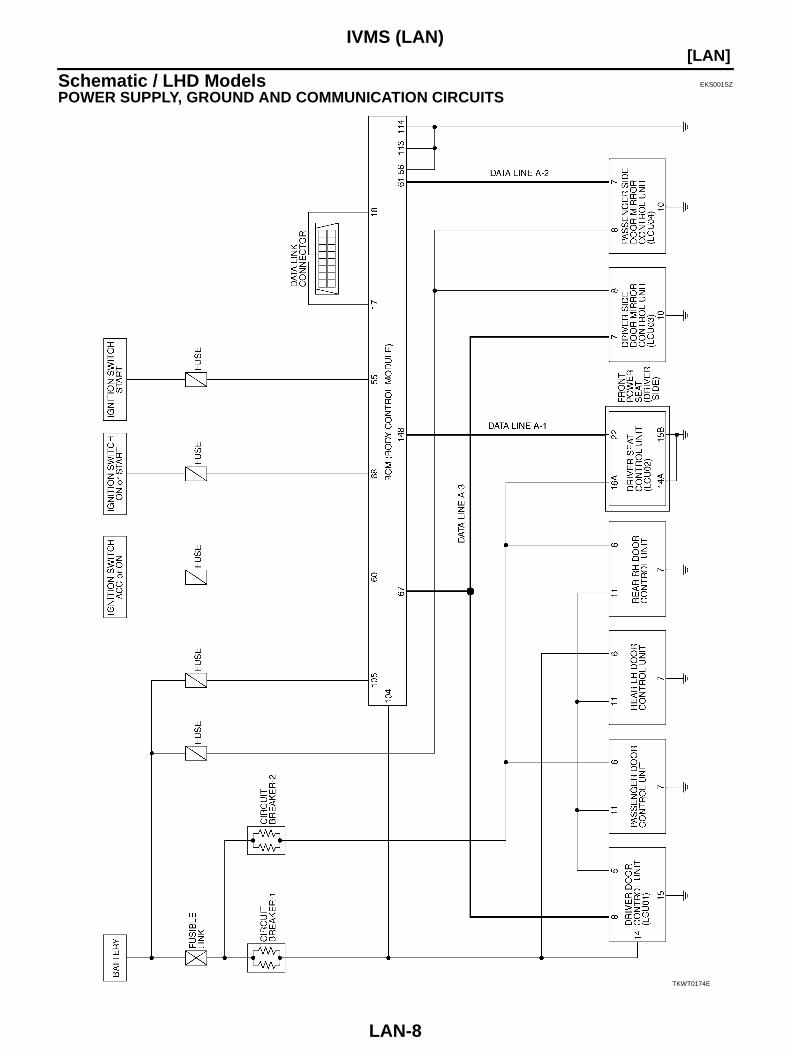
Schematic / LHD Models EKS001SZ
POWER SUPPLY, GROUND AND COMMUNICATION CIRCUITS
TKWT0174E
IVMS (LAN)
LAN-9
[LAN]
C
D
E
F
G
H
I
J
L
M
A
B
LAN
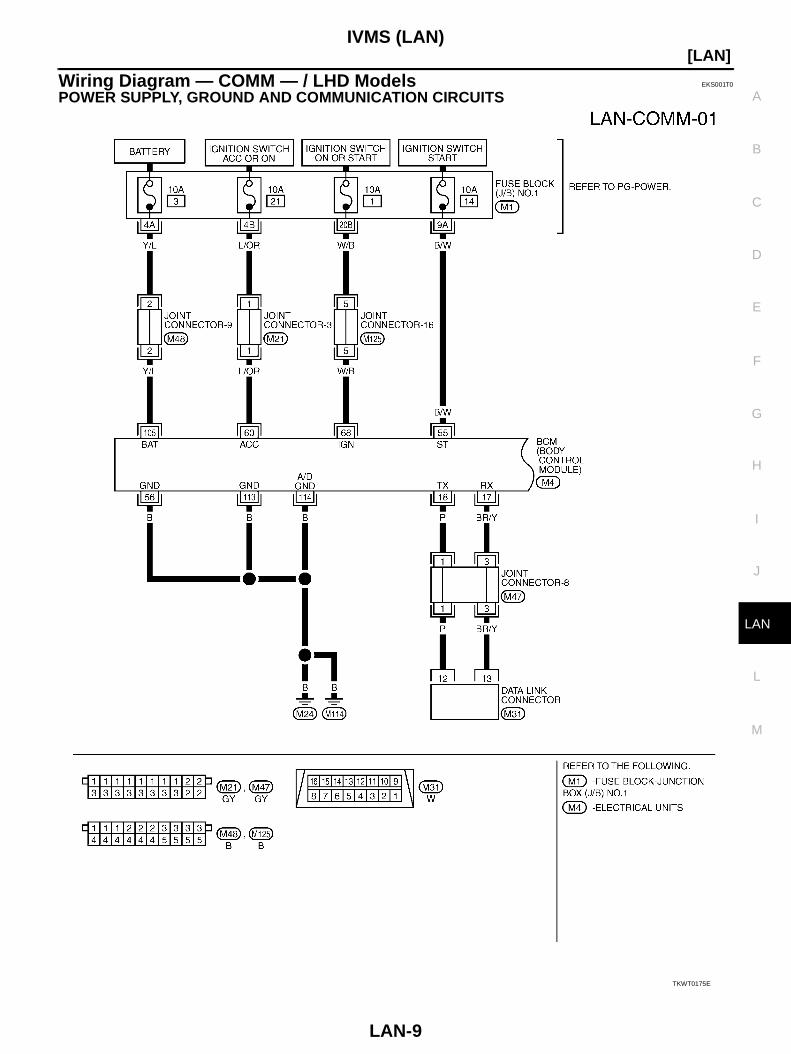
Wiring Diagram — COMM — / LHD Models EKS001T0
POWER SUPPLY, GROUND AND COMMUNICATION CIRCUITS
TKWT0175E
LAN-10
[LAN]IVMS (LAN)
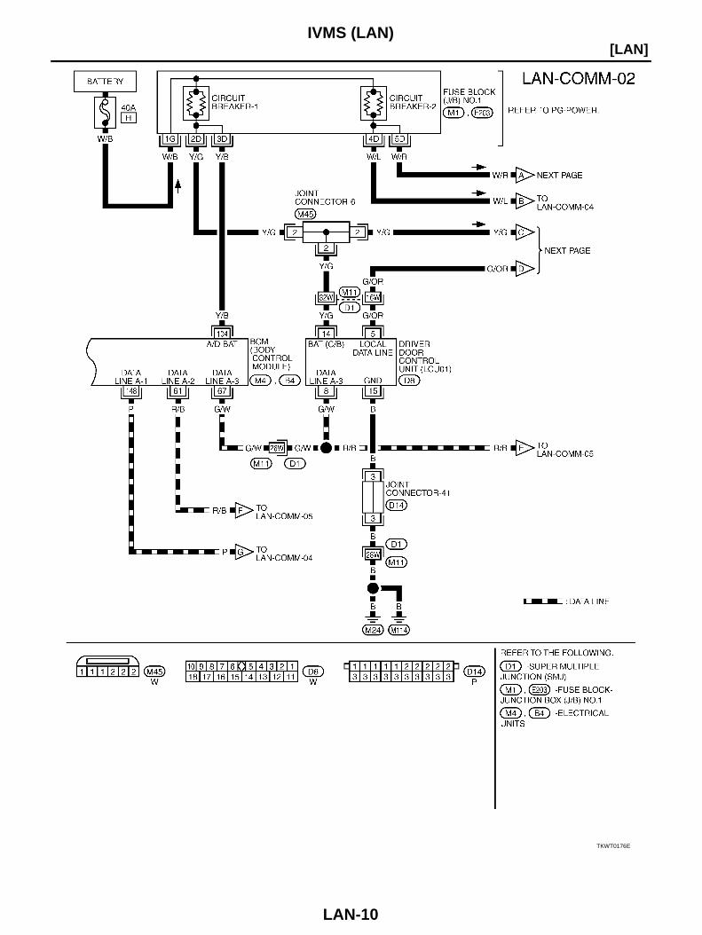
TKWT0176E
IVMS (LAN)
LAN-11
[LAN]
C
D
E
F
G
H
I
J
L
M
A
B
LAN
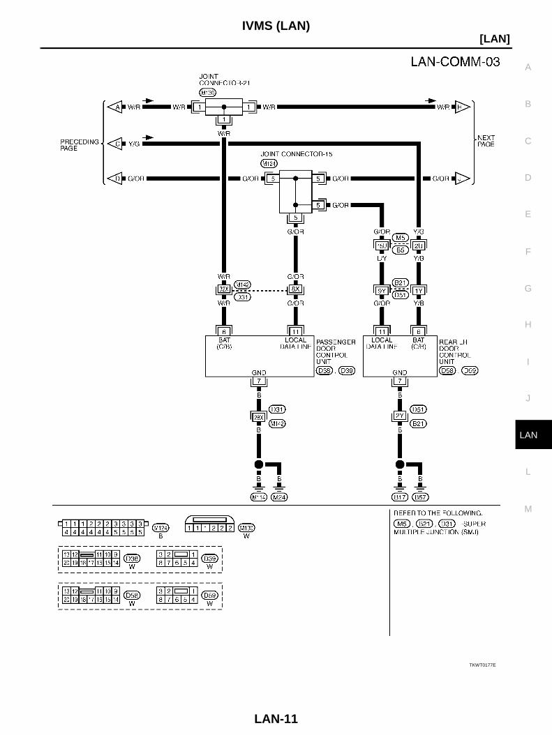
TKWT0177E
LAN-12
[LAN]IVMS (LAN)
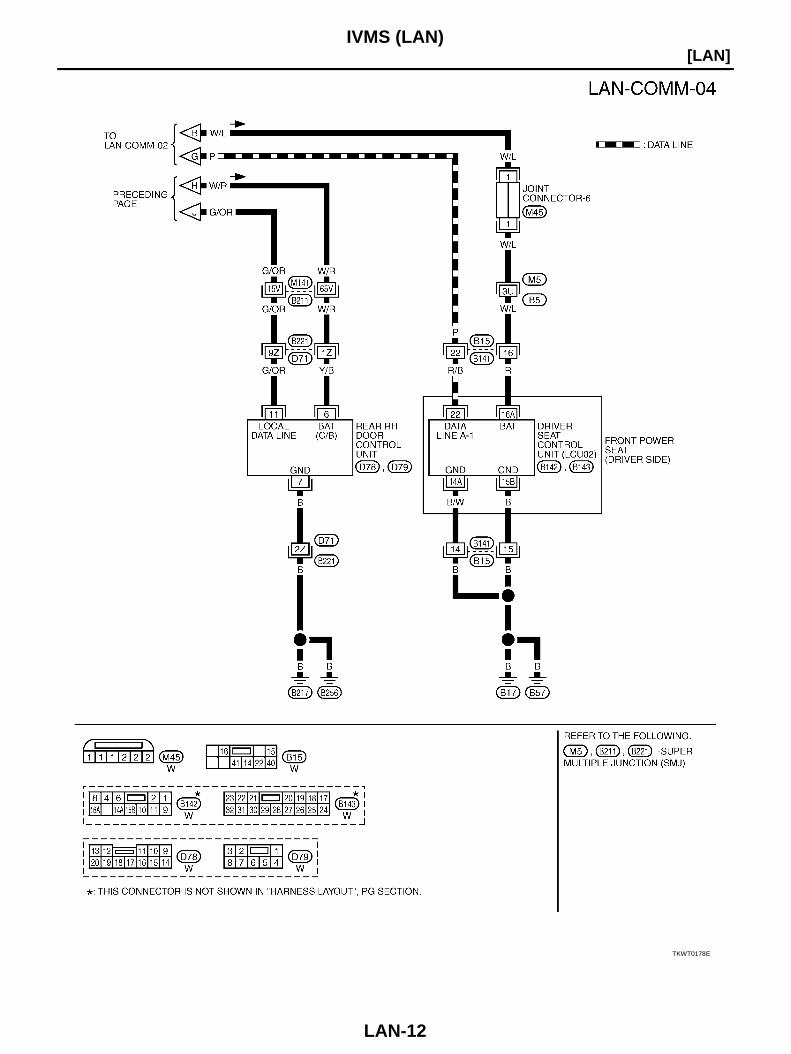
TKWT0178E
IVMS (LAN)
LAN-13
[LAN]
C
D
E
F
G
H
I
J
L
M
A
B
LAN
WITH DOOR MIRROR SYSTEM
TKWT0179E
LAN-14
[LAN]IVMS (LAN)
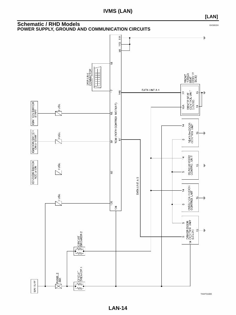
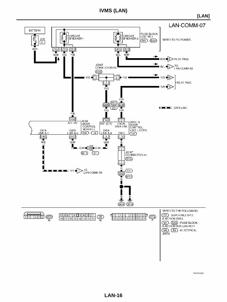
Schematic / RHD Models EKS002IX
POWER SUPPLY, GROUND AND COMMUNICATION CIRCUITS
TKWT0180E
IVMS (LAN)
LAN-15
[LAN]
C
D
E
F
G
H
I
J
L
M
A
B
LAN
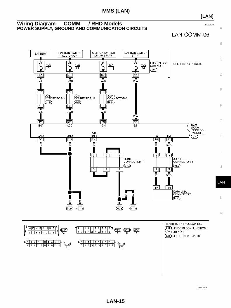
Wiring Diagram — COMM — / RHD Models EKS002IY
POWER SUPPLY, GROUND AND COMMUNICATION CIRCUITS
TKWT0181E
LAN-16
[LAN]IVMS (LAN)
TKWT0182E
IVMS (LAN)
LAN-17
[LAN]
C
D
E
F
G
H
I
J
L
M
A
B
LAN
TKWT0183E
LAN-18
[LAN]IVMS (LAN)
TKWT0184E
IVMS (LAN)
LAN-19
[LAN]
C
D
E
F
G
H
I
J
L
M
A
B
LAN
Schematic — BCM — EKS001T1
TKWM0528E
LAN-20
[LAN]IVMS (LAN)
TKWM0529E
IVMS (LAN)
LAN-21
[LAN]
C
D
E
F
G
H
I
J
L
M
A
B
LAN
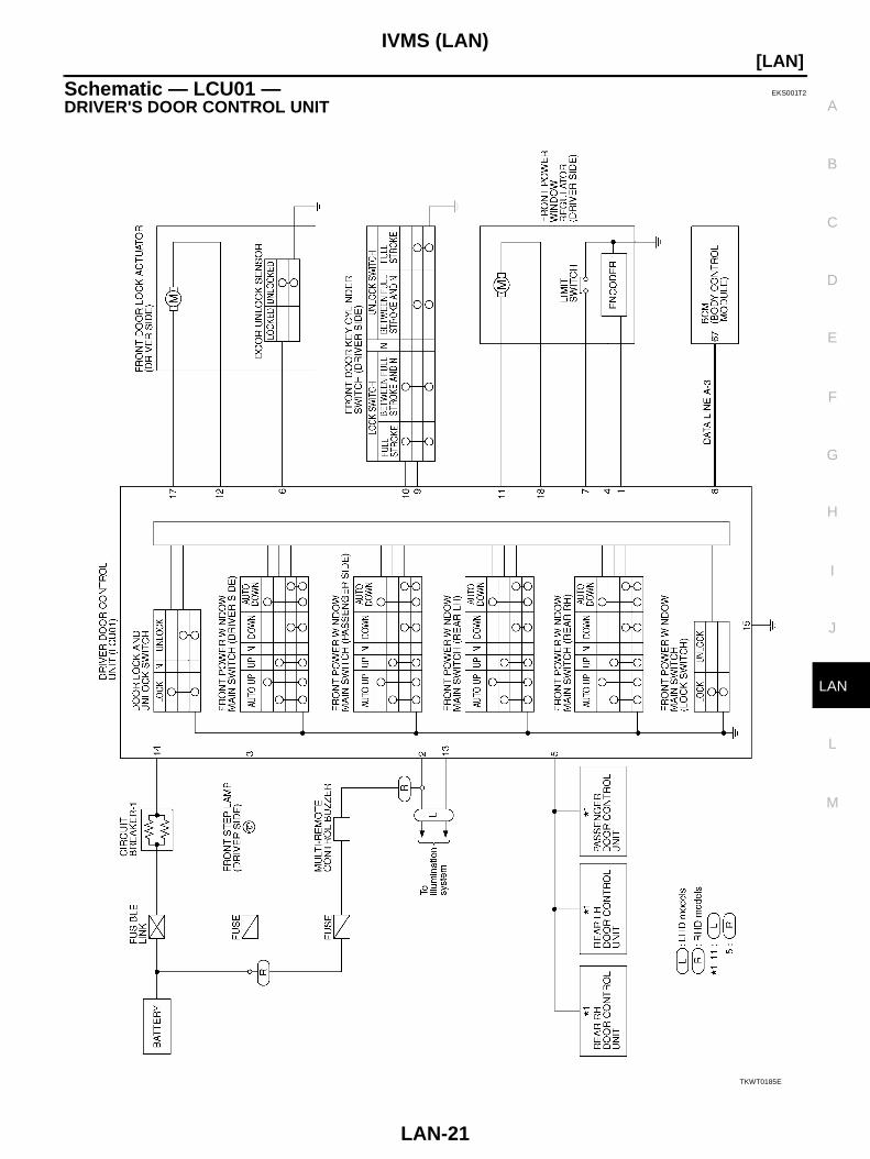
Schematic — LCU01 — EKS001T2
DRIVER'S DOOR CONTROL UNIT
TKWT0185E

LAN-22
[LAN]IVMS (LAN)
Schematic — LCU02 — EKS001T3
DRIVER'S SEAT CONTROL UNIT
TKWT0186E

IVMS (LAN)
LAN-23
[LAN]
C
D
E
F
G
H
I
J
L
M
A
B
LAN
Schematic — LCU03 — EKS001T4
DRIVER'S SIDE DOOR MIRROR CONTROL UNIT (WITH DOOR MIRROR MEMORY SYSTEM)
TKWT0187E
LAN-24
[LAN]IVMS (LAN)
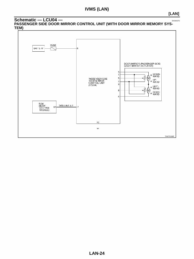
Schematic — LCU04 — EKS001T5
PASSENGER SIDE DOOR MIRROR CONTROL UNIT (WITH DOOR MIRROR MEMORY SYS-TEM)
TKWT0188E
PRECAUTIONS
LAN-25
[CAN]
C
D
E
F
G
H
I
J
L
M
A
B
LAN
[CAN]PRECAUTIONS PFP:00001
Precautions for Supplemental Restraint System (SRS) “AIR BAG” and “SEAT BELT PRE-TENSIONER” EKS001T6
The Supplemental Restraint System such as “AIR BAG” and “SEAT BELT PRE-TENSIONER”, used alongwith a front seat belt, helps to reduce the risk or severity of injury to the driver and front passenger for certaintypes of collision. Information necessary to service the system safely is included in the SRS and SB section ofthis Service Manual.WARNING: To avoid rendering the SRS inoperative, which could increase the risk of personal injury or death
in the event of a collision which would result in air bag inflation, all maintenance must be per-formed by an authorized NISSAN/INFINITI dealer.
Improper maintenance, including incorrect removal and installation of the SRS, can lead to per-sonal injury caused by unintentional activation of the system. For removal of Spiral Cable and AirBag Module, see the SRS section.
Do not use electrical test equipment on any circuit related to the SRS unless instructed to in thisService Manual. SRS wiring harnesses can be identified by yellow and/or orange harness connec-tors.
Precautions For Trouble Diagnosis EKS001T7
CAN SYSTEM Do not apply voltage of 7.0V or higher to the measurement terminals. Use the tester with its open terminal voltage being 7.0V or less.
Precautions For Harness Repair EKS001T8
CAN SYSTEM Solder the repaired parts, and wrap with tape. [Frays of twisted
line must be within 110 mm (4.33 in)]
Do not perform bypass wire connections for the repair parts.(The spliced wire will become separated and the characteristicsof twisted line will be lost.)
PKIA0306E
PKIA0307E
LAN-26
[CAN]CAN COMMUNICATION
CAN COMMUNICATION PFP:23710
System Description EKS001T9
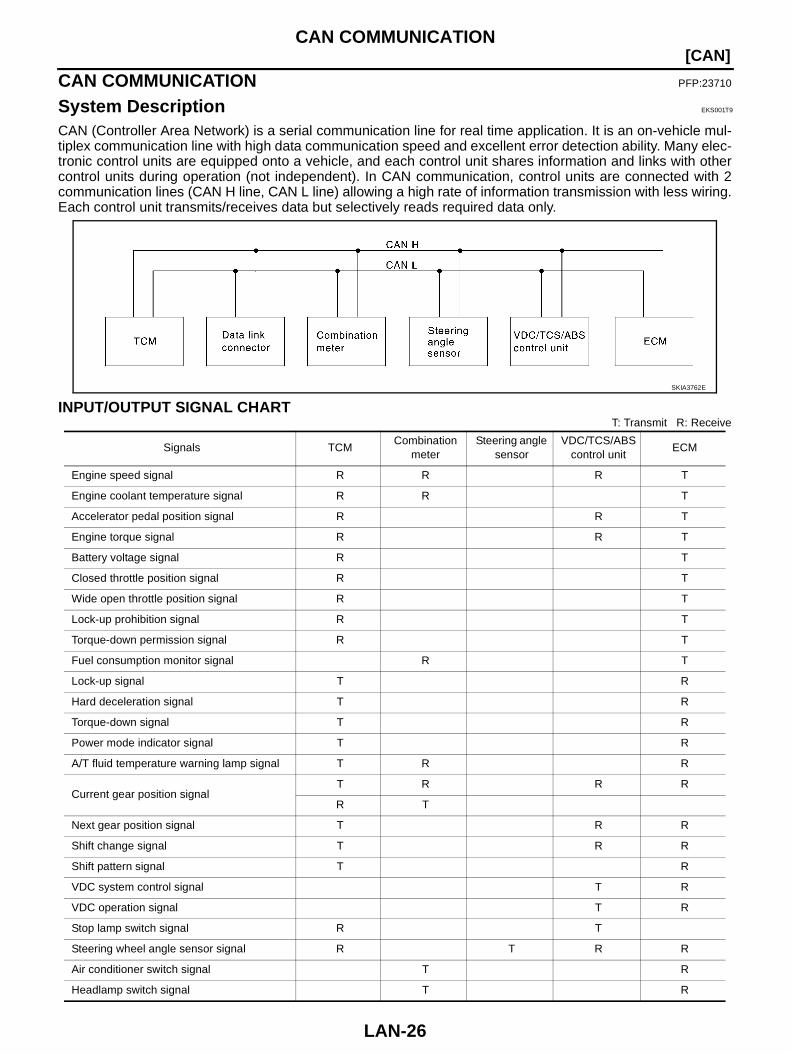
CAN (Controller Area Network) is a serial communication line for real time application. It is an on-vehicle mul-tiplex communication line with high data communication speed and excellent error detection ability. Many elec-tronic control units are equipped onto a vehicle, and each control unit shares information and links with othercontrol units during operation (not independent). In CAN communication, control units are connected with 2communication lines (CAN H line, CAN L line) allowing a high rate of information transmission with less wiring.Each control unit transmits/receives data but selectively reads required data only.
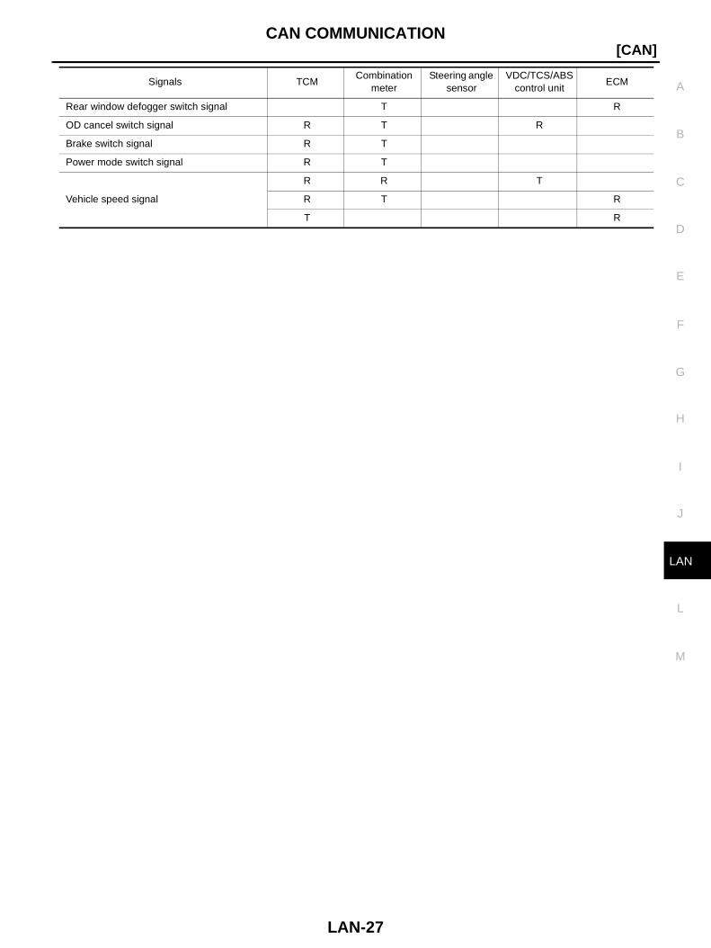
INPUT/OUTPUT SIGNAL CHARTT: Transmit R: Receive
SKIA3762E
Signals TCMCombination
meterSteering angle
sensorVDC/TCS/ABS
control unitECM
Engine speed signal R R R T
Engine coolant temperature signal R R T
Accelerator pedal position signal R R T
Engine torque signal R R T
Battery voltage signal R T
Closed throttle position signal R T
Wide open throttle position signal R T
Lock-up prohibition signal R T
Torque-down permission signal R T
Fuel consumption monitor signal R T
Lock-up signal T R
Hard deceleration signal T R
Torque-down signal T R
Power mode indicator signal T R
A/T fluid temperature warning lamp signal T R R
Current gear position signalT R R R
R T
Next gear position signal T R R
Shift change signal T R R
Shift pattern signal T R
VDC system control signal T R
VDC operation signal T R
Stop lamp switch signal R T
Steering wheel angle sensor signal R T R R
Air conditioner switch signal T R
Headlamp switch signal T R
CAN COMMUNICATION
LAN-27
[CAN]
C
D
E
F
G
H
I
J
L
M
A
B
LAN
Rear window defogger switch signal T R
OD cancel switch signal R T R
Brake switch signal R T
Power mode switch signal R T
Vehicle speed signal
R R T
R T R
T R
Signals TCMCombination
meterSteering angle
sensorVDC/TCS/ABS
control unitECM
LAN-28
[CAN]CAN SYSTEM (FOR LHD MODELS)
CAN SYSTEM (FOR LHD MODELS) PFP:23710
System Description EKS001TA
CAN (Controller Area Network) is a serial communication line for real time application. It is an on-vehicle mul-tiplex communication line with high data communication speed and excellent error detection ability. Many elec-tronic control units are equipped onto a vehicle, and each control unit shares information and links with othercontrol units during operation (not independent). In CAN communication, control units are connected with 2communication lines (CAN H line, CAN L line) allowing a high rate of information transmission with less wiring.Each control unit transmits/receives data but selectively reads required data only.
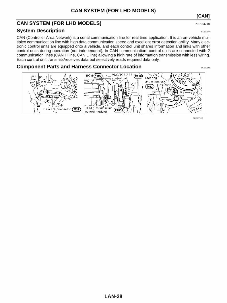
Component Parts and Harness Connector Location EKS001TB
SKIA3772E
CAN SYSTEM (FOR LHD MODELS)
LAN-29
[CAN]
C
D
E
F
G
H
I
J
L
M
A
B
LAN
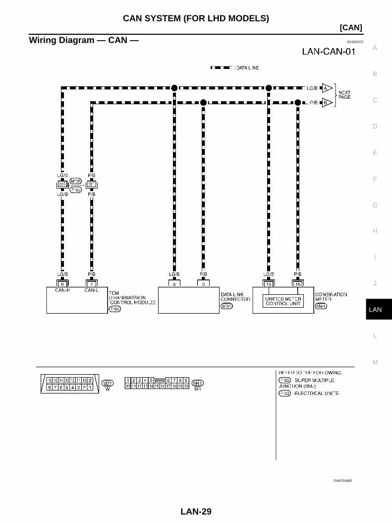
Wiring Diagram — CAN — EKS001TC
TKWT0189E
LAN-30
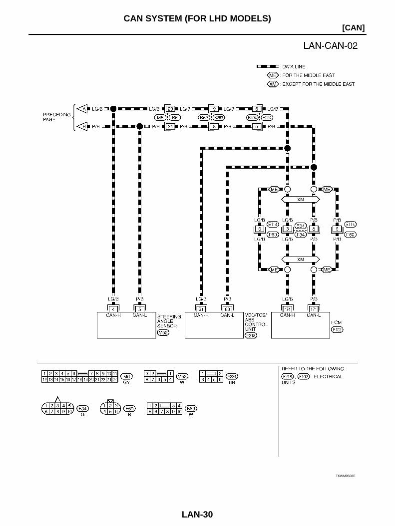
[CAN]CAN SYSTEM (FOR LHD MODELS)
TKWM0508E
CAN SYSTEM (FOR LHD MODELS)
LAN-31
[CAN]
C
D
E
F
G
H
I
J
L
M
A
B
LAN
Work Flow EKS001TD
1. Print all the data of “SELF-DIAG RESULTS” and “DATA MONITOR” for “ENGINE”, “A/T”, and “VDC” dis-played on CONSULT-II. Refer to the following: EC-126, "DTC U1000 CAN COMMUNICATION LINE" for “ENGINE” AT-74, "DTC U1000 CAN COMMUNICATION LINE" for “A/T” BRC-53, "Inspection 1 CAN Communication Line or VDC/TCS/ABS Control Unit and Steering Angle
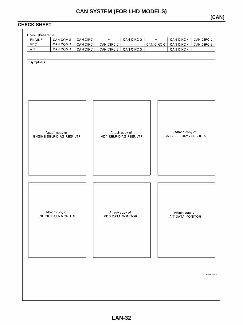
Sensor System" for “VDC”2. Attach the printed sheet of “SELF-DIAG RESULTS” and “DATA MONITOR” onto the check sheet. Refer to
LAN-32, "CHECK SHEET"3. Based on the data monitor results, put “v” marks onto the items with “UNKWN” or “NG” in the check sheet
table. Refer to LAN-32, "CHECK SHEET"NOTE:If “NG” is displayed on “CAN COMM” for the diagnosed control unit, replace the control unit.
4. According to the check sheet results (example), start inspection. Refer to LAN-33, "CHECK SHEETRESULTS (EXAMPLE)"
LAN-32
[CAN]CAN SYSTEM (FOR LHD MODELS)
CHECK SHEET
PKIA0295E
CAN SYSTEM (FOR LHD MODELS)
LAN-33
[CAN]
C
D
E
F
G
H
I
J
L
M
A
B
LAN
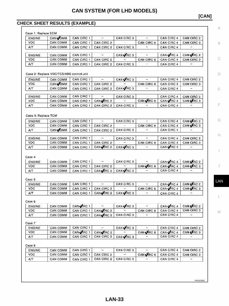
CHECK SHEET RESULTS (EXAMPLE)
PKIA0296E
LAN-34
[CAN]CAN SYSTEM (FOR LHD MODELS)
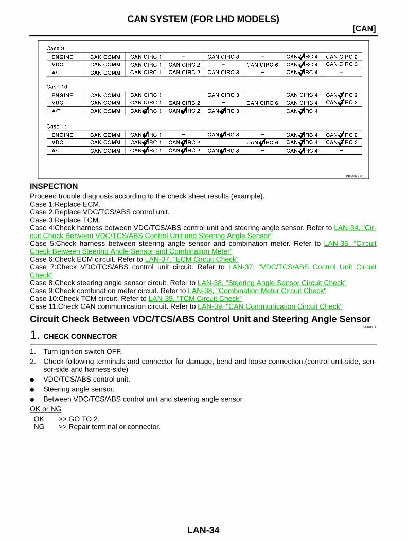
INSPECTIONProceed trouble diagnosis according to the check sheet results (example).Case 1:Replace ECM.Case 2:Replace VDC/TCS/ABS control unit.Case 3:Replace TCM.Case 4:Check harness between VDC/TCS/ABS control unit and steering angle sensor. Refer to LAN-34, "Cir-cuit Check Between VDC/TCS/ABS Control Unit and Steering Angle Sensor"Case 5:Check harness between steering angle sensor and combination meter. Refer to LAN-36, "CircuitCheck Between Steering Angle Sensor and Combination Meter"Case 6:Check ECM circuit. Refer to LAN-37, "ECM Circuit Check"Case 7:Check VDC/TCS/ABS control unit circuit. Refer to LAN-37, "VDC/TCS/ABS Control Unit CircuitCheck"Case 8:Check steering angle sensor circuit. Refer to LAN-38, "Steering Angle Sensor Circuit Check"Case 9:Check combination meter circuit. Refer to LAN-38, "Combination Meter Circuit Check"Case 10:Check TCM circuit. Refer to LAN-39, "TCM Circuit Check"Case 11:Check CAN communication circuit. Refer to LAN-39, "CAN Communication Circuit Check"
Circuit Check Between VDC/TCS/ABS Control Unit and Steering Angle SensorEKS001TE
1. CHECK CONNECTOR
1. Turn ignition switch OFF.2. Check following terminals and connector for damage, bend and loose connection.(control unit-side, sen-
sor-side and harness-side) VDC/TCS/ABS control unit. Steering angle sensor. Between VDC/TCS/ABS control unit and steering angle sensor.OK or NGOK >> GO TO 2.NG >> Repair terminal or connector.
PKIA0297E
CAN SYSTEM (FOR LHD MODELS)
LAN-35
[CAN]
C
D
E
F
G
H
I
J
L
M
A
B
LAN
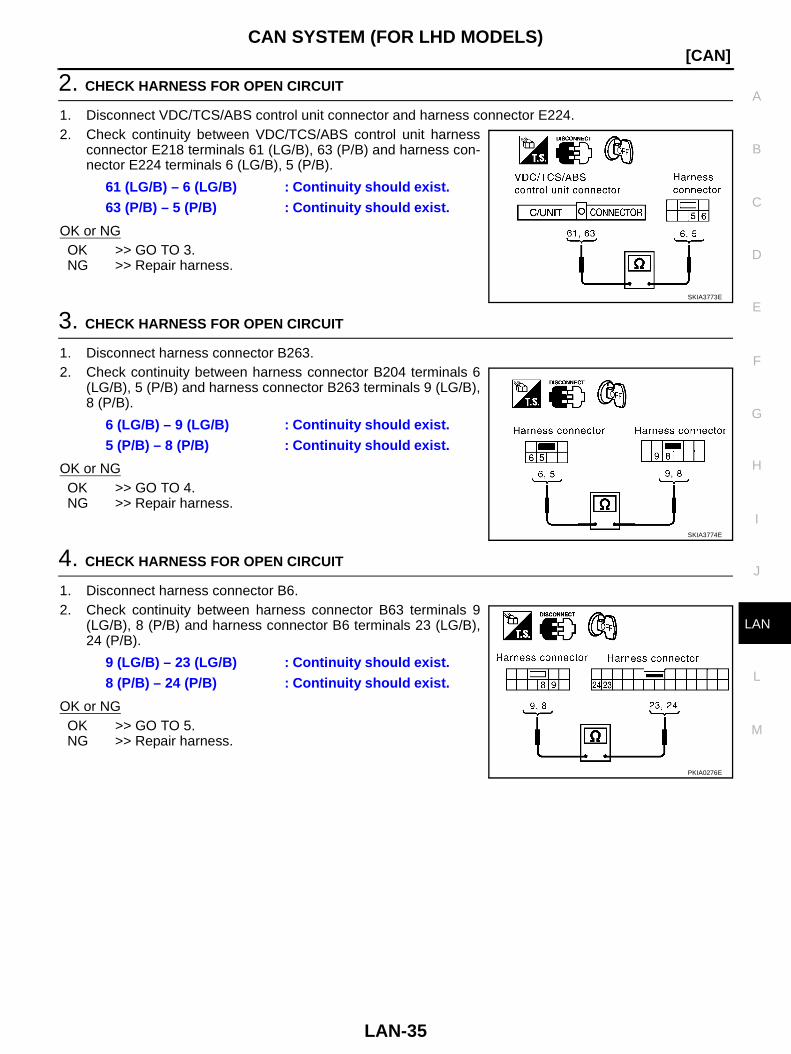
2. CHECK HARNESS FOR OPEN CIRCUIT
1. Disconnect VDC/TCS/ABS control unit connector and harness connector E224.2. Check continuity between VDC/TCS/ABS control unit harness
connector E218 terminals 61 (LG/B), 63 (P/B) and harness con-nector E224 terminals 6 (LG/B), 5 (P/B).
OK or NGOK >> GO TO 3.NG >> Repair harness.
3. CHECK HARNESS FOR OPEN CIRCUIT
1. Disconnect harness connector B263.2. Check continuity between harness connector B204 terminals 6
(LG/B), 5 (P/B) and harness connector B263 terminals 9 (LG/B),8 (P/B).
OK or NGOK >> GO TO 4.NG >> Repair harness.
4. CHECK HARNESS FOR OPEN CIRCUIT
1. Disconnect harness connector B6.2. Check continuity between harness connector B63 terminals 9
(LG/B), 8 (P/B) and harness connector B6 terminals 23 (LG/B),24 (P/B).
OK or NGOK >> GO TO 5.NG >> Repair harness.
61 (LG/B) – 6 (LG/B) : Continuity should exist.63 (P/B) – 5 (P/B) : Continuity should exist.
SKIA3773E
6 (LG/B) – 9 (LG/B) : Continuity should exist.5 (P/B) – 8 (P/B) : Continuity should exist.
SKIA3774E
9 (LG/B) – 23 (LG/B) : Continuity should exist.8 (P/B) – 24 (P/B) : Continuity should exist.
PKIA0276E
LAN-36
[CAN]CAN SYSTEM (FOR LHD MODELS)
5. CHECK HARNESS FOR OPEN CIRCUIT
1. Disconnect steering angle sensor connector.2. Check continuity between harness connector M6 terminals 23
(LG/B), 24 (P/B) and steering angle sensor harness connectorM52 terminals 4 (LG/B), 5 (P/B).
OK or NGOK >> Reconnect all connectors to perform “SELF-DIAG
RESULTS” and “DATA MONITOR” for “ENGINE”, “A/T”, and “VDC”. Refer to the following: EC-126, "DTC U1000 CAN COMMUNICATION LINE"
for “ENGINE” AT-74, "DTC U1000 CAN COMMUNICATION LINE" for “A/T” BRC-53, "Inspection 1 CAN Communication Line or VDC/TCS/ABS Control Unit and Steering
Angle Sensor System" for “VDC”NG >> Repair harness.
Circuit Check Between Steering Angle Sensor and Combination Meter EKS001TF
1. CHECK CONNECTOR
1. Turn ignition switch OFF.2. Check following terminals and connector for damage, bend and loose connection. (sensor-side, meter-
side and harness-side) Steering angle sensor. Combination meter.OK or NGOK >> GO TO 2.NG >> Repair terminal or connector.
2. CHECK HARNESS FOR OPEN CIRCUIT
1. Disconnect steering angle sensor connector and combination meter connector.2. Check continuity between steering angle sensor harness con-
nector M52 terminals 4 (LG/B), 5 (P/B) and combination meterharness connector M41 terminals 15 (LG/B), 16 (P/B).
OK or NGOK >> Reconnect all connectors to perform “SELF-DIAG
RESULTS” and “DATA MONITOR” for “ENGINE”, “A/T”, and “VDC”. Refer to the following: EC-126, "DTC U1000 CAN COMMUNICATION LINE"
for “ENGINE” AT-74, "DTC U1000 CAN COMMUNICATION LINE" for “A/T” BRC-53, "Inspection 1 CAN Communication Line or VDC/TCS/ABS Control Unit and Steering
Angle Sensor System" for “VDC”NG >> Repair harness.
23 (LG/B) – 4 (LG/B) : Continuity should exist.24 (P/B) – 5 (P/B) : Continuity should exist.
SKIA3775E
4 (LG/B) – 15 (LG/B) : Continuity should exist.5 (P/B) – 16 (P/B) : Continuity should exist.
SKIA3776E

CAN SYSTEM (FOR LHD MODELS)
LAN-37
[CAN]
C
D
E
F
G
H
I
J
L
M
A
B
LAN
ECM Circuit Check EKS001TG
1. CHECK CONNECTOR
1. Turn ignition switch OFF.2. Check following terminals and connector for damage, bend and loose connection. (control module-side
and harness-side) ECM. Harness connector F34. (Except for the middle east) Harness connector E34. (Except for the middle east) Harness connector F60. (For the middle east) Harness connector E114. (For the middle east)OK or NGOK >> GO TO 2.NG >> Repair terminal or connector.
2. CHECK HARNESS FOR OPEN CIRCUIT
1. Disconnect ECM connector.2. Check resistance between ECM harness connector F102 termi-
nals 174 (LG/B) and 171 (P/B).
OK or NGOK >> Replace ECM.NG >> Repair harness between harness connector E224 and
ECM.
VDC/TCS/ABS Control Unit Circuit Check EKS001TH
1. CHECK CONNECTOR
1. Turn ignition switch OFF.2. Check the terminals and connector of VDC/TCS/ABS control unit for damage, bend and loose connection.
(control unit-side and harness-side)OK or NGOK >> GO TO 2.NG >> Repair terminal or connector.
2. CHECK HARNESS FOR OPEN CIRCUIT
1. Disconnect VDC/TCS/ABS control unit connector.2. Check resistance between VDC/TCS/ABS control unit harness
connector E218 terminals 61 (LG/B) and 63 (P/B).
OK or NGOK >> Replace VDC/TCS/ABS control unit.NG >> Repair harness between harness connector E224 and
VDC/TCS/ABS control unit.
174 (LG/B) – 171 (P/B) : Approx. 108 – 132Ω
PKIA0279E
61 (LG/B) – 63 (P/B) : Approx. 54 – 66Ω
PKIA0280E
LAN-38
[CAN]CAN SYSTEM (FOR LHD MODELS)
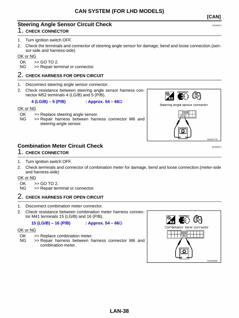
Steering Angle Sensor Circuit Check EKS001TI
1. CHECK CONNECTOR
1. Turn ignition switch OFF.2. Check the terminals and connector of steering angle sensor for damage, bend and loose connection.(sen-
sor-side and harness-side)OK or NGOK >> GO TO 2.NG >> Repair terminal or connector.
2. CHECK HARNESS FOR OPEN CIRCUIT
1. Disconnect steering angle sensor connector.2. Check resistance between steering angle sensor harness con-
nector M52 terminals 4 (LG/B) and 5 (P/B).
OK or NGOK >> Replace steering angle sensor.NG >> Repair harness between harness connector M6 and
steering angle sensor.
Combination Meter Circuit Check EKS001TJ
1. CHECK CONNECTOR
1. Turn ignition switch OFF.2. Check terminals and connector of combination meter for damage, bend and loose connection.(meter-side
and harness-side)OK or NGOK >> GO TO 2.NG >> Repair terminal or connector.
2. CHECK HARNESS FOR OPEN CIRCUIT
1. Disconnect combination meter connector.2. Check resistance between combination meter harness connec-
tor M41 terminals 15 (LG/B) and 16 (P/B).
OK or NGOK >> Replace combination meter.NG >> Repair harness between harness connector M6 and
combination meter.
4 (LG/B) – 5 (P/B) : Approx. 54 – 66Ω
SKIA3777E
15 (LG/B) – 16 (P/B) : Approx. 54 – 66Ω
PKIA0282E
CAN SYSTEM (FOR LHD MODELS)
LAN-39
[CAN]
C
D
E
F
G
H
I
J
L
M
A
B
LAN
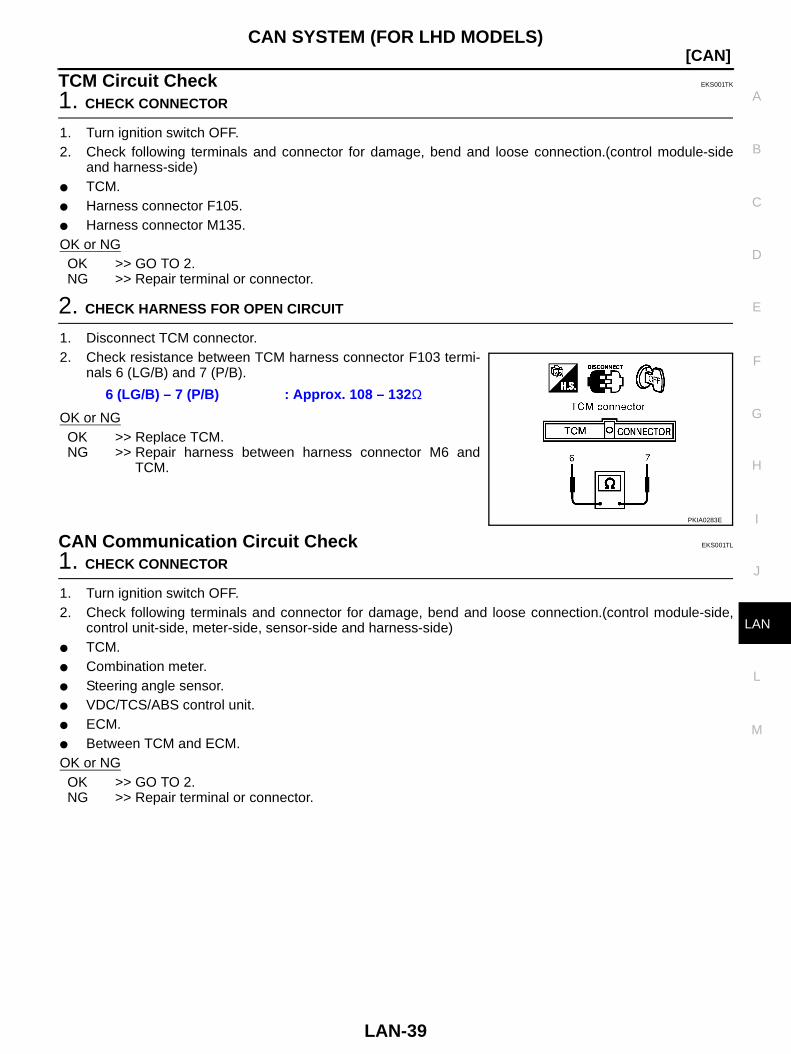
TCM Circuit Check EKS001TK
1. CHECK CONNECTOR
1. Turn ignition switch OFF.2. Check following terminals and connector for damage, bend and loose connection.(control module-side
and harness-side) TCM. Harness connector F105. Harness connector M135.OK or NGOK >> GO TO 2.NG >> Repair terminal or connector.
2. CHECK HARNESS FOR OPEN CIRCUIT
1. Disconnect TCM connector.2. Check resistance between TCM harness connector F103 termi-
nals 6 (LG/B) and 7 (P/B).
OK or NGOK >> Replace TCM.NG >> Repair harness between harness connector M6 and
TCM.
CAN Communication Circuit Check EKS001TL
1. CHECK CONNECTOR
1. Turn ignition switch OFF.2. Check following terminals and connector for damage, bend and loose connection.(control module-side,
control unit-side, meter-side, sensor-side and harness-side) TCM. Combination meter. Steering angle sensor. VDC/TCS/ABS control unit. ECM. Between TCM and ECM.OK or NGOK >> GO TO 2.NG >> Repair terminal or connector.
6 (LG/B) – 7 (P/B) : Approx. 108 – 132Ω
PKIA0283E
LAN-40
[CAN]CAN SYSTEM (FOR LHD MODELS)
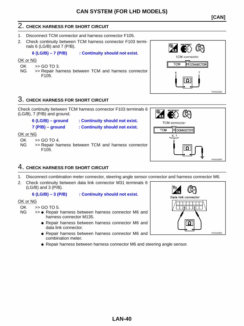
2. CHECK HARNESS FOR SHORT CIRCUIT
1. Disconnect TCM connector and harness connector F105.2. Check continuity between TCM harness connector F103 termi-
nals 6 (LG/B) and 7 (P/B).
OK or NGOK >> GO TO 3.NG >> Repair harness between TCM and harness connector
F105.
3. CHECK HARNESS FOR SHORT CIRCUIT
Check continuity between TCM harness connector F103 terminals 6(LG/B), 7 (P/B) and ground.
OK or NGOK >> GO TO 4.NG >> Repair harness between TCM and harness connector
F105.
4. CHECK HARNESS FOR SHORT CIRCUIT
1. Disconnect combination meter connector, steering angle sensor connector and harness connector M6.2. Check continuity between data link connector M31 terminals 6
(LG/B) and 3 (P/B).
OK or NGOK >> GO TO 5.NG >> Repair harness between harness connector M6 and
harness connector M135. Repair harness between harness connector M6 and
data link connector. Repair harness between harness connector M6 and
combination meter. Repair harness between harness connector M6 and steering angle sensor.
6 (LG/B) – 7 (P/B) : Continuity should not exist.
PKIA0283E
6 (LG/B) – ground : Continuity should not exist.7 (P/B) – ground : Continuity should not exist.
PKIA0284E
6 (LG/B) – 3 (P/B) : Continuity should not exist.
PKIA0285E
CAN SYSTEM (FOR LHD MODELS)
LAN-41
[CAN]
C
D
E
F
G
H
I
J
L
M
A
B
LAN
5. CHECK HARNESS FOR SHORT CIRCUIT
Check continuity between data link connector M31 terminals 6 (LG/B), 3 (P/B) and ground.
OK or NGOK >> GO TO 6.NG >> Repair harness between harness connector M6 and
harness connector M135. Repair harness between harness connector M6 and
data link connector. Repair harness between harness connector M6 and combination meter. Repair harness between harness connector M6 and steering angle sensor.
6. CHECK HARNESS FOR SHORT CIRCUIT
1. Disconnect harness connector B63.2. Check continuity between harness connector B6 terminals 23
(LG/B) and 24 (P/B).
OK or NGOK >> GO TO 7.NG >> Repair harness between harness connector B6 and har-
ness connector B63.
7. CHECK HARNESS FOR SHORT CIRCUIT
Check continuity between harness connector B6 terminals 23 (LG/B), 24 (P/B) and ground.
OK or NGOK >> GO TO 8.NG >> Repair harness between harness connector B6 and har-
ness connector B63.
6 (LG/B) – ground : Continuity should not exist.3 (P/B) – ground : Continuity should not exist.
PKIA0286E
23 (LG/B) – 24 (P/B) : Continuity should not exist.
PKIA0287E
23 (LG/B) – ground : Continuity should not exist.24 (P/B) – ground : Continuity should not exist.
PKIA0288E

LAN-42
[CAN]CAN SYSTEM (FOR LHD MODELS)
8. CHECK HARNESS FOR SHORT CIRCUIT
1. Disconnect harness connector B204.2. Check continuity between harness connector B263 terminals 9
(LG/B) and 8 (P/B).
OK or NGOK >> GO TO 9.NG >> Repair harness between harness connector B263 and
harness connector B204.
9. CHECK HARNESS FOR SHORT CIRCUIT
Check continuity between harness connector B263 terminals 9 (LG/B), 8 (P/B) and ground.
OK or NGOK >> GO TO 10.NG >> Repair harness between harness connector B263 and
harness connector B204.
10. CHECK HARNESS FOR SHORT CIRCUIT
1. Disconnect VDC/TCS/ABS control unit connector and harness connector E34 (Except for the middle east)or harness connector E114 (For the middle east).
2. Check continuity between VDC/TCS/ABS control unit harnessconnector E218 terminals 61 (LG/B) and 63 (P/B).
OK or NGOK >> GO TO 11.NG >> Repair harness between harness connector E34 and
harness connector E224.(Except for the middle east) Repair harness between harness connector E114 and
harness connector E224.(For the middle east) Repair harness between harness connector E224
and VDC/TCS/ABS control unit.
9 (LG/B) – 8 (P/B) : Continuity should not exist.
PKIA0289E
9 (LG/B) – ground : Continuity should not exist.8 (P/B) – ground : Continuity should not exist.
PKIA0290E
61 (LG/B) – 63 (P/B) : Continuity should not exist.
PKIA0280E
CAN SYSTEM (FOR LHD MODELS)
LAN-43
[CAN]
C
D
E
F
G
H
I
J
L
M
A
B
LAN
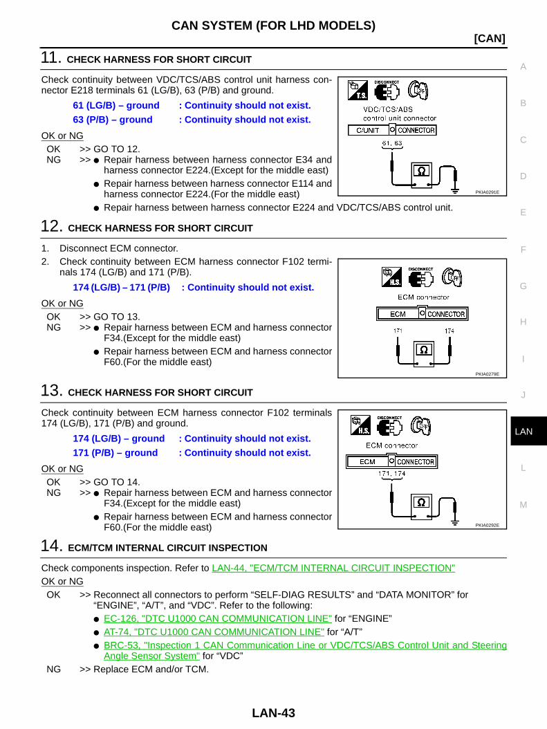
11. CHECK HARNESS FOR SHORT CIRCUIT
Check continuity between VDC/TCS/ABS control unit harness con-nector E218 terminals 61 (LG/B), 63 (P/B) and ground.
OK or NGOK >> GO TO 12.NG >> Repair harness between harness connector E34 and
harness connector E224.(Except for the middle east) Repair harness between harness connector E114 and
harness connector E224.(For the middle east) Repair harness between harness connector E224 and VDC/TCS/ABS control unit.
12. CHECK HARNESS FOR SHORT CIRCUIT
1. Disconnect ECM connector.2. Check continuity between ECM harness connector F102 termi-
nals 174 (LG/B) and 171 (P/B).
OK or NGOK >> GO TO 13.NG >> Repair harness between ECM and harness connector
F34.(Except for the middle east) Repair harness between ECM and harness connector
F60.(For the middle east)
13. CHECK HARNESS FOR SHORT CIRCUIT
Check continuity between ECM harness connector F102 terminals174 (LG/B), 171 (P/B) and ground.
OK or NGOK >> GO TO 14.NG >> Repair harness between ECM and harness connector
F34.(Except for the middle east) Repair harness between ECM and harness connector
F60.(For the middle east)
14. ECM/TCM INTERNAL CIRCUIT INSPECTION
Check components inspection. Refer to LAN-44, "ECM/TCM INTERNAL CIRCUIT INSPECTION"OK or NGOK >> Reconnect all connectors to perform “SELF-DIAG RESULTS” and “DATA MONITOR” for
“ENGINE”, “A/T”, and “VDC”. Refer to the following: EC-126, "DTC U1000 CAN COMMUNICATION LINE" for “ENGINE” AT-74, "DTC U1000 CAN COMMUNICATION LINE" for “A/T” BRC-53, "Inspection 1 CAN Communication Line or VDC/TCS/ABS Control Unit and Steering
Angle Sensor System" for “VDC”NG >> Replace ECM and/or TCM.
61 (LG/B) – ground : Continuity should not exist.63 (P/B) – ground : Continuity should not exist.
PKIA0291E
174 (LG/B) – 171 (P/B) : Continuity should not exist.
PKIA0279E
174 (LG/B) – ground : Continuity should not exist.171 (P/B) – ground : Continuity should not exist.
PKIA0292E
LAN-44
[CAN]CAN SYSTEM (FOR LHD MODELS)
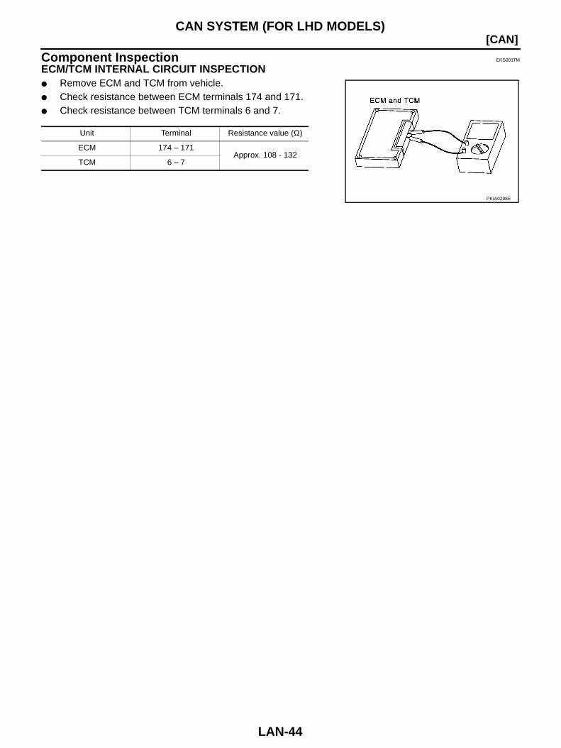
Component Inspection EKS001TM
ECM/TCM INTERNAL CIRCUIT INSPECTION Remove ECM and TCM from vehicle. Check resistance between ECM terminals 174 and 171. Check resistance between TCM terminals 6 and 7.
Unit Terminal Resistance value (Ω)
ECM 174 – 171Approx. 108 - 132
TCM 6 – 7
PKIA0298E
CAN SYSTEM (FOR RHD MODELS)
LAN-45
[CAN]
C
D
E
F
G
H
I
J
L
M
A
B
LAN
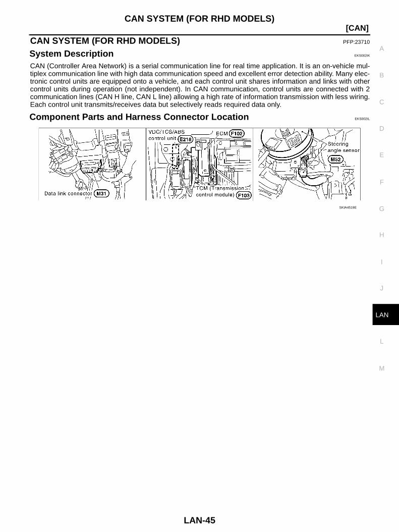
CAN SYSTEM (FOR RHD MODELS) PFP:23710
System Description EKS002IK
CAN (Controller Area Network) is a serial communication line for real time application. It is an on-vehicle mul-tiplex communication line with high data communication speed and excellent error detection ability. Many elec-tronic control units are equipped onto a vehicle, and each control unit shares information and links with othercontrol units during operation (not independent). In CAN communication, control units are connected with 2communication lines (CAN H line, CAN L line) allowing a high rate of information transmission with less wiring.Each control unit transmits/receives data but selectively reads required data only.
Component Parts and Harness Connector Location EKS002IL
SKIA4519E
LAN-46
[CAN]CAN SYSTEM (FOR RHD MODELS)
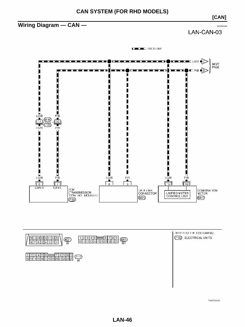
Wiring Diagram — CAN — EKS002IM
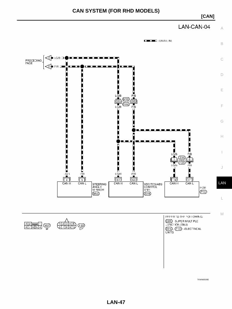
TKWT0191E
CAN SYSTEM (FOR RHD MODELS)
LAN-47
[CAN]
C
D
E
F
G
H
I
J
L
M
A
B
LAN
TKWM0509E
LAN-48
[CAN]CAN SYSTEM (FOR RHD MODELS)
Work Flow EKS002IN
1. Print all the data of “SELF-DIAG RESULTS” and “DATA MONITOR” for “ENGINE”, “A/T”, and “VDC” dis-played on CONSULT-II. Refer to the following: EC-126, "DTC U1000 CAN COMMUNICATION LINE" for “ENGINE” AT-74, "DTC U1000 CAN COMMUNICATION LINE" for “A/T” BRC-53, "Inspection 1 CAN Communication Line or VDC/TCS/ABS Control Unit and Steering Angle
Sensor System" for “VDC”2. Attach the printed sheet of “SELF-DIAG RESULTS” and “DATA MONITOR” onto the check sheet. Refer to
LAN-49, "CHECK SHEET"3. Based on the data monitor results, put “v” marks onto the items with “UNKWN” or “NG” in the check sheet
table. Refer to LAN-49, "CHECK SHEET"NOTE:If “NG” is displayed on “CAN COMM” for the diagnosed control unit, replace the control unit.
4. According to the check sheet results (example), start inspection. Refer to LAN-50, "CHECK SHEETRESULTS (EXAMPLE)"

CAN SYSTEM (FOR RHD MODELS)
LAN-49
[CAN]
C
D
E
F
G
H
I
J
L
M
A
B
LAN
CHECK SHEET
PKIA0295E
LAN-50
[CAN]CAN SYSTEM (FOR RHD MODELS)
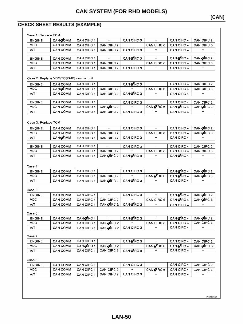
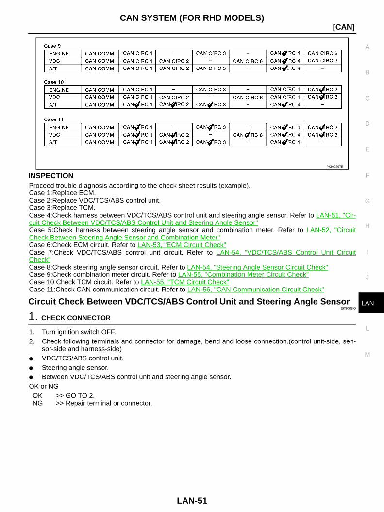
CHECK SHEET RESULTS (EXAMPLE)
PKIA0296E
CAN SYSTEM (FOR RHD MODELS)
LAN-51
[CAN]
C
D
E
F
G
H
I
J
L
M
A
B
LAN
INSPECTIONProceed trouble diagnosis according to the check sheet results (example).Case 1:Replace ECM.Case 2:Replace VDC/TCS/ABS control unit.Case 3:Replace TCM.Case 4:Check harness between VDC/TCS/ABS control unit and steering angle sensor. Refer to LAN-51, "Cir-cuit Check Between VDC/TCS/ABS Control Unit and Steering Angle Sensor"Case 5:Check harness between steering angle sensor and combination meter. Refer to LAN-52, "CircuitCheck Between Steering Angle Sensor and Combination Meter"Case 6:Check ECM circuit. Refer to LAN-53, "ECM Circuit Check"Case 7:Check VDC/TCS/ABS control unit circuit. Refer to LAN-54, "VDC/TCS/ABS Control Unit CircuitCheck"Case 8:Check steering angle sensor circuit. Refer to LAN-54, "Steering Angle Sensor Circuit Check"Case 9:Check combination meter circuit. Refer to LAN-55, "Combination Meter Circuit Check"Case 10:Check TCM circuit. Refer to LAN-55, "TCM Circuit Check"Case 11:Check CAN communication circuit. Refer to LAN-56, "CAN Communication Circuit Check"
Circuit Check Between VDC/TCS/ABS Control Unit and Steering Angle SensorEKS002IO
1. CHECK CONNECTOR
1. Turn ignition switch OFF.2. Check following terminals and connector for damage, bend and loose connection.(control unit-side, sen-
sor-side and harness-side) VDC/TCS/ABS control unit. Steering angle sensor. Between VDC/TCS/ABS control unit and steering angle sensor.OK or NGOK >> GO TO 2.NG >> Repair terminal or connector.
PKIA0297E
LAN-52
[CAN]CAN SYSTEM (FOR RHD MODELS)
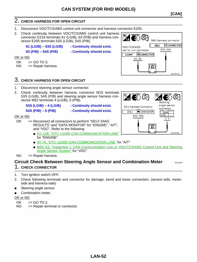
2. CHECK HARNESS FOR OPEN CIRCUIT
1. Disconnect VDC/TCS/ABS control unit connector and harness connector E205.2. Check continuity between VDC/TCS/ABS control unit harness
connector E218 terminals 61 (LG/B), 63 (P/B) and harness con-nector E205 terminals 53S (LG/B), 54S (P/B).
OK or NGOK >> GO TO 3.NG >> Repair harness.
3. CHECK HARNESS FOR OPEN CIRCUIT
1. Disconnect steering angle sensor connector.2. Check continuity between harness connector M15 terminals
53S (LG/B), 54S (P/B) and steering angle sensor harness con-nector M52 terminals 4 (LG/B), 5 (P/B).
OK or NGOK >> Reconnect all connectors to perform “SELF-DIAG
RESULTS” and “DATA MONITOR” for “ENGINE”, “A/T”, and “VDC”. Refer to the following: EC-126, "DTC U1000 CAN COMMUNICATION LINE"
for “ENGINE” AT-74, "DTC U1000 CAN COMMUNICATION LINE" for “A/T” BRC-53, "Inspection 1 CAN Communication Line or VDC/TCS/ABS Control Unit and Steering
Angle Sensor System" for “VDC”NG >> Repair harness.
Circuit Check Between Steering Angle Sensor and Combination Meter EKS002IP
1. CHECK CONNECTOR
1. Turn ignition switch OFF.2. Check following terminals and connector for damage, bend and loose connection. (sensor-side, meter-
side and harness-side) Steering angle sensor. Combination meter.OK or NGOK >> GO TO 2.NG >> Repair terminal or connector.
61 (LG/B) – 53S (LG/B) : Continuity should exist.63 (P/B) – 54S (P/B) : Continuity should exist.
SKIA0914E
53S (LG/B) – 4 (LG/B) : Continuity should exist.54S (P/B) – 5 (P/B) : Continuity should exist.
SKIA4529E
CAN SYSTEM (FOR RHD MODELS)
LAN-53
[CAN]
C
D
E
F
G
H
I
J
L
M
A
B
LAN
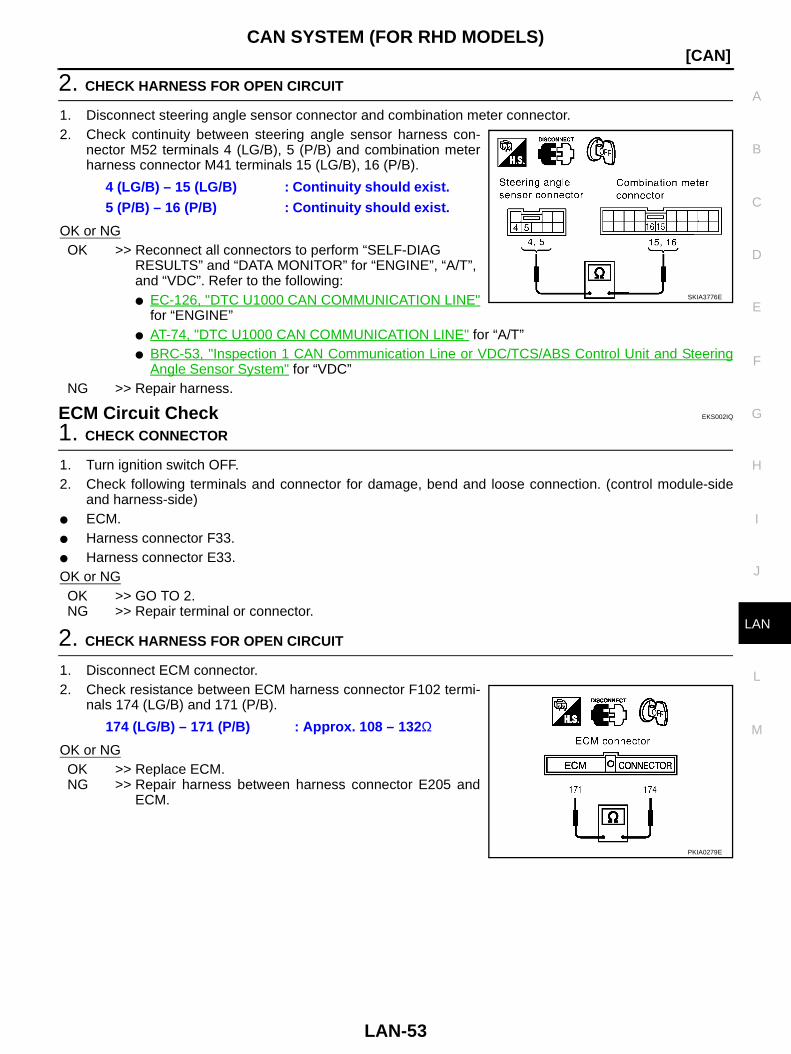
2. CHECK HARNESS FOR OPEN CIRCUIT
1. Disconnect steering angle sensor connector and combination meter connector.2. Check continuity between steering angle sensor harness con-
nector M52 terminals 4 (LG/B), 5 (P/B) and combination meterharness connector M41 terminals 15 (LG/B), 16 (P/B).
OK or NGOK >> Reconnect all connectors to perform “SELF-DIAG
RESULTS” and “DATA MONITOR” for “ENGINE”, “A/T”, and “VDC”. Refer to the following: EC-126, "DTC U1000 CAN COMMUNICATION LINE"
for “ENGINE” AT-74, "DTC U1000 CAN COMMUNICATION LINE" for “A/T” BRC-53, "Inspection 1 CAN Communication Line or VDC/TCS/ABS Control Unit and Steering
Angle Sensor System" for “VDC”NG >> Repair harness.
ECM Circuit Check EKS002IQ
1. CHECK CONNECTOR
1. Turn ignition switch OFF.2. Check following terminals and connector for damage, bend and loose connection. (control module-side
and harness-side) ECM. Harness connector F33. Harness connector E33.OK or NGOK >> GO TO 2.NG >> Repair terminal or connector.
2. CHECK HARNESS FOR OPEN CIRCUIT
1. Disconnect ECM connector.2. Check resistance between ECM harness connector F102 termi-
nals 174 (LG/B) and 171 (P/B).
OK or NGOK >> Replace ECM.NG >> Repair harness between harness connector E205 and
ECM.
4 (LG/B) – 15 (LG/B) : Continuity should exist.5 (P/B) – 16 (P/B) : Continuity should exist.
SKIA3776E
174 (LG/B) – 171 (P/B) : Approx. 108 – 132Ω
PKIA0279E
LAN-54
[CAN]CAN SYSTEM (FOR RHD MODELS)
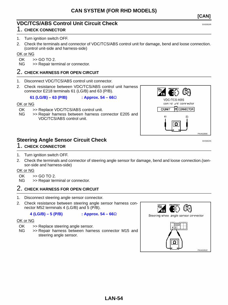
VDC/TCS/ABS Control Unit Circuit Check EKS002IR
1. CHECK CONNECTOR
1. Turn ignition switch OFF.2. Check the terminals and connector of VDC/TCS/ABS control unit for damage, bend and loose connection.
(control unit-side and harness-side)OK or NGOK >> GO TO 2.NG >> Repair terminal or connector.
2. CHECK HARNESS FOR OPEN CIRCUIT
1. Disconnect VDC/TCS/ABS control unit connector.2. Check resistance between VDC/TCS/ABS control unit harness
connector E218 terminals 61 (LG/B) and 63 (P/B).
OK or NGOK >> Replace VDC/TCS/ABS control unit.NG >> Repair harness between harness connector E205 and
VDC/TCS/ABS control unit.
Steering Angle Sensor Circuit Check EKS002IS
1. CHECK CONNECTOR
1. Turn ignition switch OFF.2. Check the terminals and connector of steering angle sensor for damage, bend and loose connection.(sen-
sor-side and harness-side)OK or NGOK >> GO TO 2.NG >> Repair terminal or connector.
2. CHECK HARNESS FOR OPEN CIRCUIT
1. Disconnect steering angle sensor connector.2. Check resistance between steering angle sensor harness con-
nector M52 terminals 4 (LG/B) and 5 (P/B).
OK or NGOK >> Replace steering angle sensor.NG >> Repair harness between harness connector M15 and
steering angle sensor.
61 (LG/B) – 63 (P/B) : Approx. 54 – 66Ω
PKIA0280E
4 (LG/B) – 5 (P/B) : Approx. 54 – 66Ω
PKIA0281E

CAN SYSTEM (FOR RHD MODELS)
LAN-55
[CAN]
C
D
E
F
G
H
I
J
L
M
A
B
LAN
Combination Meter Circuit Check EKS002IT
1. CHECK CONNECTOR
1. Turn ignition switch OFF.2. Check terminals and connector of combination meter for damage, bend and loose connection.(meter-side
and harness-side)OK or NGOK >> GO TO 2.NG >> Repair terminal or connector.
2. CHECK HARNESS FOR OPEN CIRCUIT
1. Disconnect combination meter connector.2. Check resistance between combination meter harness connec-
tor M41 terminals 15 (LG/B) and 16 (P/B).
OK or NGOK >> Replace combination meter.NG >> Repair harness between harness connector M15 and
combination meter.
TCM Circuit Check EKS002IU
1. CHECK CONNECTOR
1. Turn ignition switch OFF.2. Check following terminals and connector for damage, bend and loose connection.(control module-side
and harness-side) TCM. Harness connector F113. Harness connector M196.OK or NGOK >> GO TO 2.NG >> Repair terminal or connector.
2. CHECK HARNESS FOR OPEN CIRCUIT
1. Disconnect TCM connector.2. Check resistance between TCM harness connector F103 termi-
nals 6 (LG/B) and 7 (P/B).
OK or NGOK >> Replace TCM.NG >> Repair harness between harness connector M15 and
TCM.
15 (LG/B) – 16 (P/B) : Approx. 54 – 66Ω
PKIA0282E
6 (LG/B) – 7 (P/B) : Approx. 108 – 132Ω
PKIA0283E
LAN-56
[CAN]CAN SYSTEM (FOR RHD MODELS)
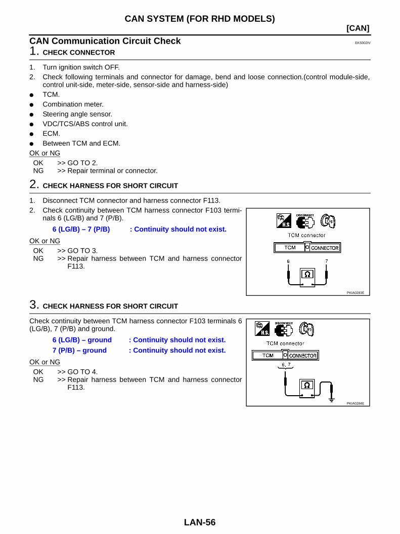
CAN Communication Circuit Check EKS002IV
1. CHECK CONNECTOR
1. Turn ignition switch OFF.2. Check following terminals and connector for damage, bend and loose connection.(control module-side,
control unit-side, meter-side, sensor-side and harness-side) TCM. Combination meter. Steering angle sensor. VDC/TCS/ABS control unit. ECM. Between TCM and ECM.OK or NGOK >> GO TO 2.NG >> Repair terminal or connector.
2. CHECK HARNESS FOR SHORT CIRCUIT
1. Disconnect TCM connector and harness connector F113.2. Check continuity between TCM harness connector F103 termi-
nals 6 (LG/B) and 7 (P/B).
OK or NGOK >> GO TO 3.NG >> Repair harness between TCM and harness connector
F113.
3. CHECK HARNESS FOR SHORT CIRCUIT
Check continuity between TCM harness connector F103 terminals 6(LG/B), 7 (P/B) and ground.
OK or NGOK >> GO TO 4.NG >> Repair harness between TCM and harness connector
F113.
6 (LG/B) – 7 (P/B) : Continuity should not exist.
PKIA0283E
6 (LG/B) – ground : Continuity should not exist.7 (P/B) – ground : Continuity should not exist.
PKIA0284E
CAN SYSTEM (FOR RHD MODELS)
LAN-57
[CAN]
C
D
E
F
G
H
I
J
L
M
A
B
LAN
4. CHECK HARNESS FOR SHORT CIRCUIT
1. Disconnect combination meter connector, steering angle sensor connector and harness connector M15.2. Check continuity between data link connector M31 terminals 6
(LG/B) and 3 (P/B).
OK or NGOK >> GO TO 5.NG >> Repair harness between harness connector M15 and
harness connector M196. Repair harness between harness connector M15 and
data link connector. Repair harness between harness connector M15 and
combination meter. Repair harness between harness connector M15 and steering angle sensor.
5. CHECK HARNESS FOR SHORT CIRCUIT
Check continuity between data link connector M31 terminals 6 (LG/B), 3 (P/B) and ground.
OK or NGOK >> GO TO 6.NG >> Repair harness between harness connector M15 and
harness connector M196. Repair harness between harness connector M15 and
data link connector. Repair harness between harness connector M15 and combination meter. Repair harness between harness connector M15 and steering angle sensor.
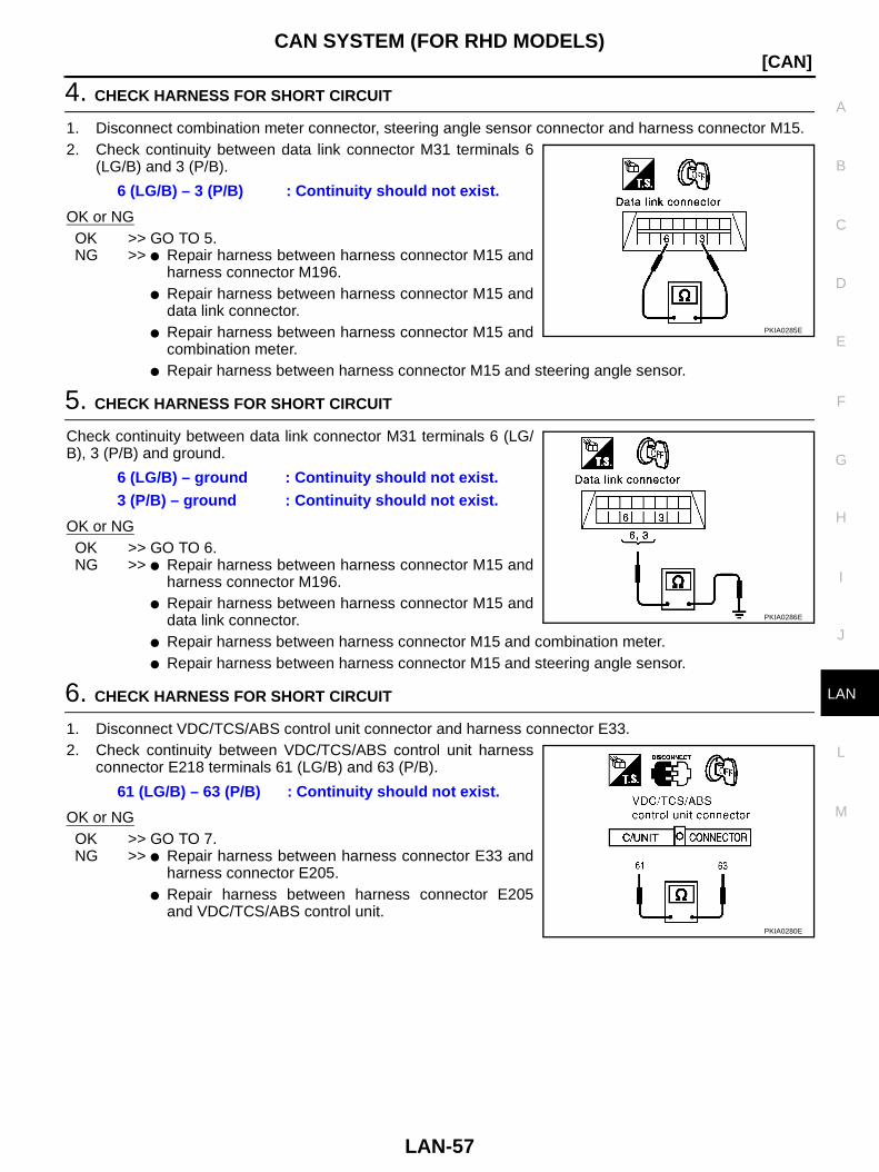
6. CHECK HARNESS FOR SHORT CIRCUIT
1. Disconnect VDC/TCS/ABS control unit connector and harness connector E33.2. Check continuity between VDC/TCS/ABS control unit harness
connector E218 terminals 61 (LG/B) and 63 (P/B).
OK or NGOK >> GO TO 7.NG >> Repair harness between harness connector E33 and
harness connector E205. Repair harness between harness connector E205
and VDC/TCS/ABS control unit.
6 (LG/B) – 3 (P/B) : Continuity should not exist.
PKIA0285E
6 (LG/B) – ground : Continuity should not exist.3 (P/B) – ground : Continuity should not exist.
PKIA0286E
61 (LG/B) – 63 (P/B) : Continuity should not exist.
PKIA0280E

LAN-58
[CAN]CAN SYSTEM (FOR RHD MODELS)
7. CHECK HARNESS FOR SHORT CIRCUIT
Check continuity between VDC/TCS/ABS control unit harness con-nector E218 terminals 61 (LG/B), 63 (P/B) and ground.
OK or NGOK >> GO TO 8.NG >> Repair harness between harness connector E33 and
harness connector E205. Repair harness between harness connector E205
and VDC/TCS/ABS control unit.
8. CHECK HARNESS FOR SHORT CIRCUIT
1. Disconnect ECM connector.2. Check continuity between ECM harness connector F102 termi-
nals 174 (LG/B) and 171 (P/B).
OK or NGOK >> GO TO 9.NG >> Repair harness between ECM and harness connector
F33.
9. CHECK HARNESS FOR SHORT CIRCUIT
Check continuity between ECM harness connector F102 terminals174 (LG/B), 171 (P/B) and ground.
OK or NGOK >> GO TO 10.NG >> Repair harness between ECM and harness connector
F33.
10. ECM/TCM INTERNAL CIRCUIT INSPECTION
Check components inspection. Refer to LAN-59, "ECM/TCM INTERNAL CIRCUIT INSPECTION"OK or NGOK >> Reconnect all connectors to perform “SELF-DIAG RESULTS” and “DATA MONITOR” for
“ENGINE”, “A/T”, and “VDC”. Refer to the following: EC-126, "DTC U1000 CAN COMMUNICATION LINE" for “ENGINE” AT-74, "DTC U1000 CAN COMMUNICATION LINE" for “A/T” BRC-53, "Inspection 1 CAN Communication Line or VDC/TCS/ABS Control Unit and Steering
Angle Sensor System" for “VDC”NG >> Replace ECM and/or TCM.
61 (LG/B) – ground : Continuity should not exist.63 (P/B) – ground : Continuity should not exist.
PKIA0291E
174 (LG/B) – 171 (P/B) : Continuity should not exist.
PKIA0279E
174 (LG/B) – ground : Continuity should not exist.171 (P/B) – ground : Continuity should not exist.
PKIA0292E
CAN SYSTEM (FOR RHD MODELS)
LAN-59
[CAN]
C
D
E
F
G
H
I
J
L
M
A
B
LAN
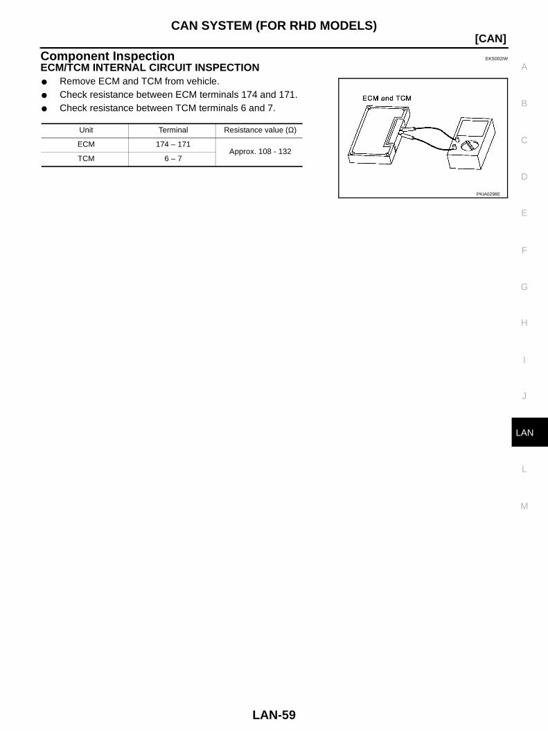
Component Inspection EKS002IW
ECM/TCM INTERNAL CIRCUIT INSPECTION Remove ECM and TCM from vehicle. Check resistance between ECM terminals 174 and 171. Check resistance between TCM terminals 6 and 7.
Unit Terminal Resistance value (Ω)
ECM 174 – 171Approx. 108 - 132
TCM 6 – 7
PKIA0298E
LAN-60
[CAN]CAN SYSTEM (FOR RHD MODELS)