lecture 11: directory-based cache...
TRANSCRIPT

Parallel Computer Architecture and Programming CMU 15-418/15-618, Spring 2016
Lecture 11:
Directory-Based Cache Coherence

CMU 15-418/618, Spring 2016
Tunes
Bang Bang (My Baby Shot Me Down)
Nancy Sinatra (Kill Bill Volume 1 Soundtrack)
“It’s such a heartbreaking thing... to have your performance silently crippled by cache lines dropping all over the place due to false sharing.”
- Nancy Sinatra

CMU 15-418/618, Spring 2016
Today: what you should know
▪ What limits the scalability of snooping-based approaches to cache coherence?
▪ How does a directory-based scheme avoid these problems?
▪ How can the storage overhead of the directory structure be reduced? (and at what cost?)
▪ How does the communication mechanism (bus, point-to-point, ring) affect scalability and design choices?

CMU 15-418/618, Spring 2016
Implementing cache coherence
ProcessorLocal Cache
ProcessorLocal Cache
ProcessorLocal Cache
ProcessorLocal Cache
Interconnect
Memory I/O
The snooping cache coherence protocols from the last lecture relied on broadcasting coherence information to all processors over the chip interconnect.
Every time a cache miss occurred, the triggering cache communicated with all other caches!
We discussed what information was communicated and what actions were taken to implement the coherence protocol.
We did not discuss how to implement broadcasts on an interconnect. (one example is to use a shared bus for the interconnect)

CMU 15-418/618, Spring 2016
Problem: scaling cache coherence to large machines
ProcessorLocal Cache
Memory
ProcessorLocal Cache
Memory
ProcessorLocal Cache
Memory
ProcessorLocal Cache
Memory
Interconnect
Recall non-uniform memory access (NUMA) shared memory systems
Idea: locating regions of memory near the processors increases scalability: it yields higher aggregate bandwidth and reduced latency (especially when there is locality in the application)
But... efficiency of NUMA system does little good if the coherence protocol can’t also be scaled!
Consider this case: processor accesses nearby memory (good...), but to ensure coherence still must broadcast to all other processors it is doing so (bad...)
Some terminology:
▪ cc-NUMA = “cache-coherent, non-uniform memory access”
▪ Distributed shared memory system (DSM): cache coherent, shared address space, but architecture implemented by physically distributed memories

CMU 15-418/618, Spring 2016
One possible solution: hierarchical snooping
ProcessorLocal Cache
ProcessorLocal Cache
ProcessorLocal Cache
ProcessorLocal Cache
Interconnect
ProcessorLocal Cache
ProcessorLocal Cache
ProcessorLocal Cache
ProcessorLocal Cache
Interconnect
Interconnect
Use snooping coherence at each level
Memory
Processor Processor Processor Processor
Interconnect
Processor Processor Processor Processor
Interconnect
InterconnectMemory Memory
Another example: with memory localized with the groups of processors, rather than centralized

CMU 15-418/618, Spring 2016
One possible solution: hierarchical snooping
ProcessorLocal Cache
ProcessorLocal Cache
ProcessorLocal Cache
ProcessorLocal Cache
Interconnect
ProcessorLocal Cache
ProcessorLocal Cache
ProcessorLocal Cache
ProcessorLocal Cache
Interconnect
Interconnect
Use snooping coherence at each level
Memory
Advantages
▪ Relatively simple to build (already must deal with similar issues due to multi-level caches)
Disadvantages
▪ The root of the network can become a bottleneck
▪ Larger latencies than direct communication
▪ Does not apply to more general network topologies (meshes, cubes)
CMU 15-418/618, Spring 2016
Scalable cache coherence using directories
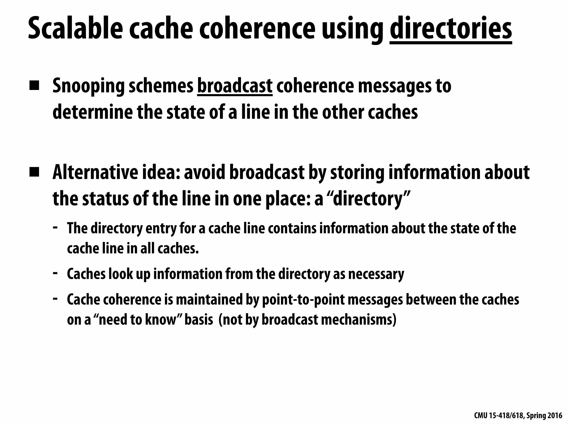
▪ Snooping schemes broadcast coherence messages to determine the state of a line in the other caches
▪ Alternative idea: avoid broadcast by storing information about the status of the line in one place: a “directory” - The directory entry for a cache line contains information about the state of the
cache line in all caches. - Caches look up information from the directory as necessary - Cache coherence is maintained by point-to-point messages between the caches
on a “need to know” basis (not by broadcast mechanisms)

CMU 15-418/618, Spring 2016
A very simple directory
Scalable Interconnect
Processor
Local Cache
Directory
Memory
. . .
One cache line of memory
One directory entry per cache line of memory
P presence bits: indicate whether processor P has line in its cache
Dirty bit: indicates line is dirty in one of the processors’ caches
CMU 15-418/618, Spring 2016
A distributed directory
Scalable Interconnect
Processor 0
Local Cache
Memory
Directory
. . .
Processor 1
Local Cache
Memory
Directory
. . .
Processor 2
Local Cache
Memory
Directory
. . .
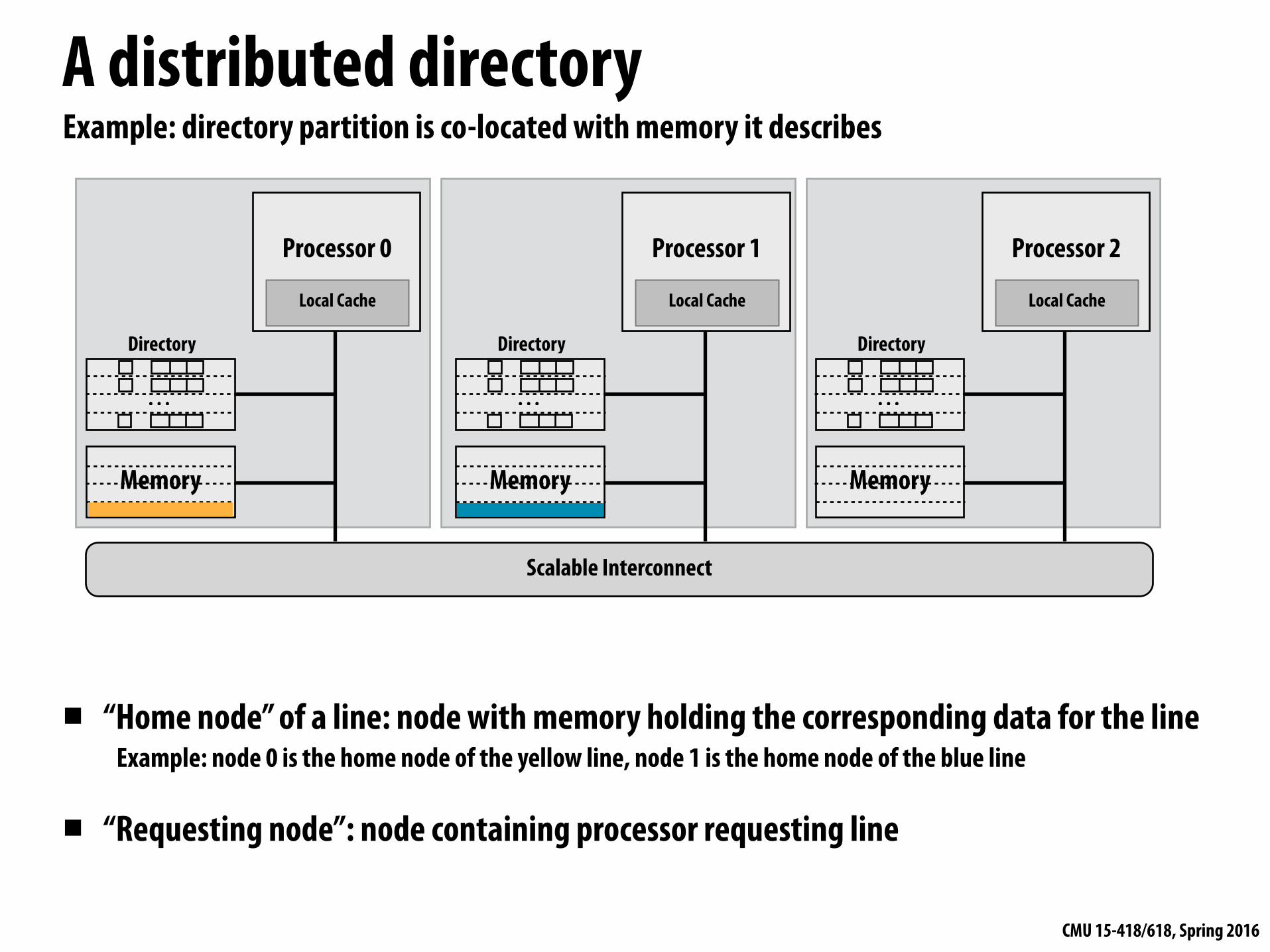
▪ “Home node” of a line: node with memory holding the corresponding data for the line Example: node 0 is the home node of the yellow line, node 1 is the home node of the blue line
▪ “Requesting node”: node containing processor requesting line
Example: directory partition is co-located with memory it describes
CMU 15-418/618, Spring 2016
Example 1: read miss to clean line
Processor 0
Local Cache
Memory
Directory
. . .
Processor 1
Local Cache
Memory
Directory
. . .
Processor 2
Local Cache
Memory
Directory
. . .
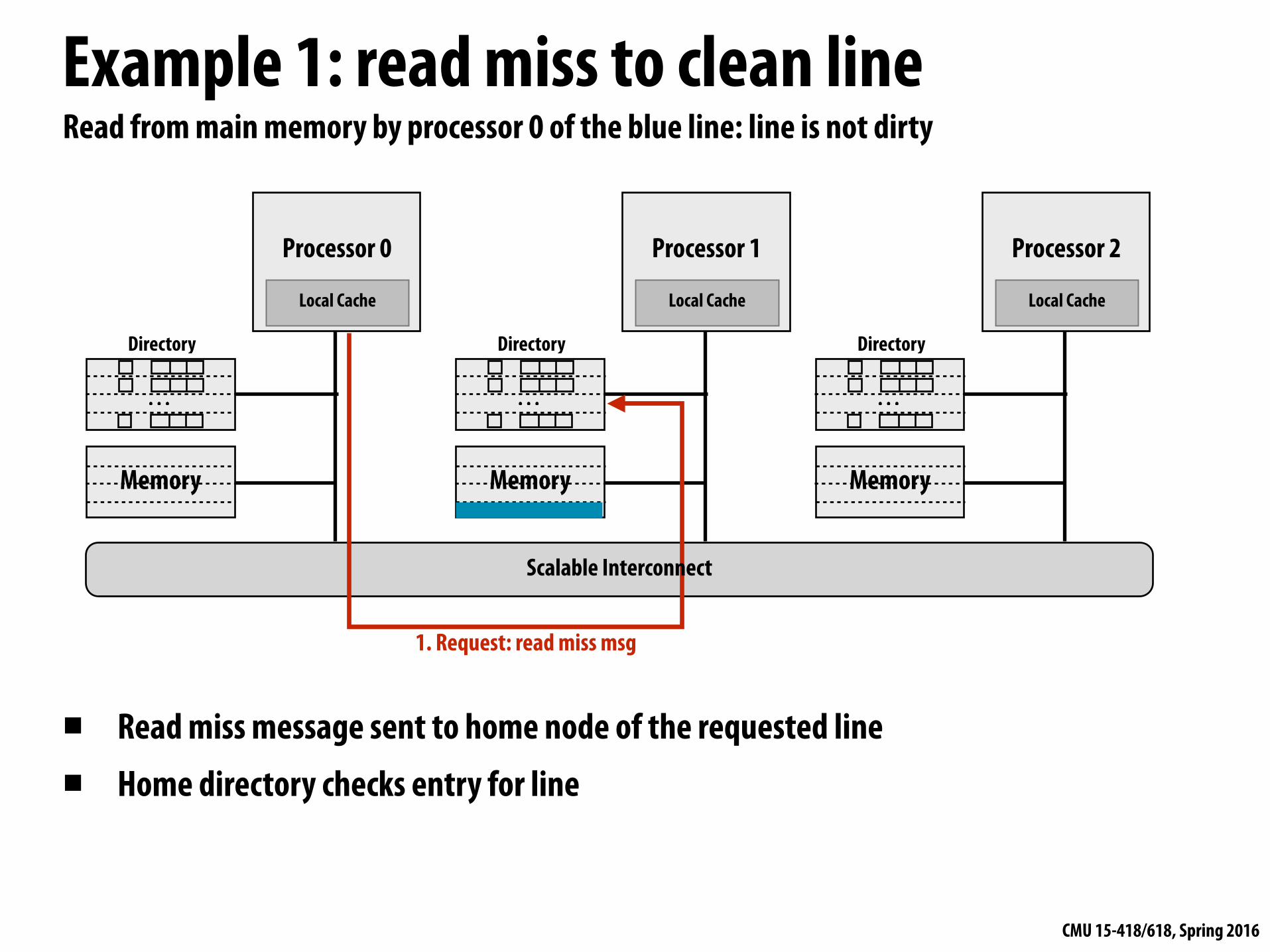
Read from main memory by processor 0 of the blue line: line is not dirty
▪ Read miss message sent to home node of the requested line
▪ Home directory checks entry for line
1. Request: read miss msg
Scalable Interconnect

CMU 15-418/618, Spring 2016
Example 1: read miss to clean line
Processor 0
Local Cache
Memory
Directory
. . .
Processor 1
Local Cache
Memory
Directory
. . .
Processor 2
Local Cache
Memory
Directory
. . .
Read from main memory by processor 0 of the blue line: line is not dirty
▪ Read miss message sent to home node of the requested line ▪ Home directory checks entry for line - If dirty bit for cache line is OFF, respond with contents from memory, set presence[0] to true
(to indicate line is cached by processor 0)
2. Response (line of data from memory)
1. Request: read miss msg
Scalable Interconnect

CMU 15-418/618, Spring 2016
Example 2: read miss to dirty line
Processor 0
Local Cache
Memory
Directory
. . .
Processor 1
Local Cache
Memory
Directory
. . .
Processor 2
Local Cache
Memory
Directory
. . .
Read from main memory by processor 0 of the blue line: line is dirty (contents in P2’s cache)
▪ If dirty bit is ON, then data must be sourced by another processor (with the most up-to-date copy of the line)
▪ Home node must tell requesting node where to find data - Responds with message providing identity of line owner (“get it from P2”)
2. Response: owner id
1. Request: read miss msg
Scalable Interconnect

CMU 15-418/618, Spring 2016
Example 2: read miss to dirty line
Processor 0
Local Cache
Memory
Directory
. . .
Processor 1
Local Cache
Memory
Directory
. . .
Processor 2
Local Cache
Memory
Directory
. . .
Read from main memory by processor 0 of the blue line: line is dirty (contents in P2’s cache)
1. If dirty bit is ON, then data must be sourced by another processor 2. Home node responds with message providing identity of line owner 3. Requesting node requests data from owner 4. Owner changes state in cache to SHARED (read only), responds to requesting node
2. Response: owner id
1. Request: read miss msg
3. Request: data4. Response: data
Scalable Interconnect

CMU 15-418/618, Spring 2016
Example 2: read miss to dirty line
Processor 0
Local Cache
Memory
Directory
. . .
Processor 1
Local Cache
Memory
Directory
. . .
Processor 2
Local Cache
Memory
Directory
. . .
Read from main memory by processor 0 of the blue line: line is dirty (contents in P2’s cache)
1. If dirty bit is ON, then data must be sourced by another processor 2. Home node responds with message providing identity of line owner 3. Requesting node requests data from owner 4. Owner responds to requesting node, changes state in cache to SHARED (read only) 5. Owner also responds to home node, home clears dirty, updates presence bits, updates memory
2. Response: owner id
1. Request: read miss msg
3. Request: data4. Response: data
5. Response: data+dir revision
Scalable Interconnect

CMU 15-418/618, Spring 2016
Example 3: write miss
Processor 0
Local Cache
Memory
Directory
. . .
Processor 1
Local Cache
Memory
Directory
. . .
Processor 2
Local Cache
Memory
Directory
. . .
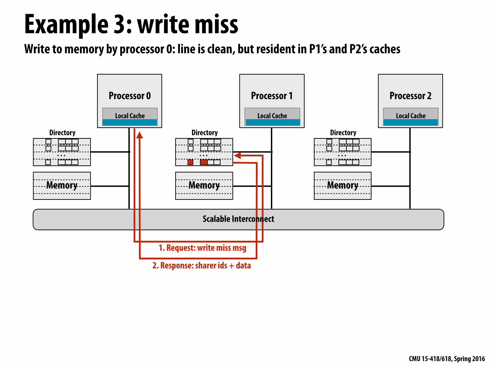
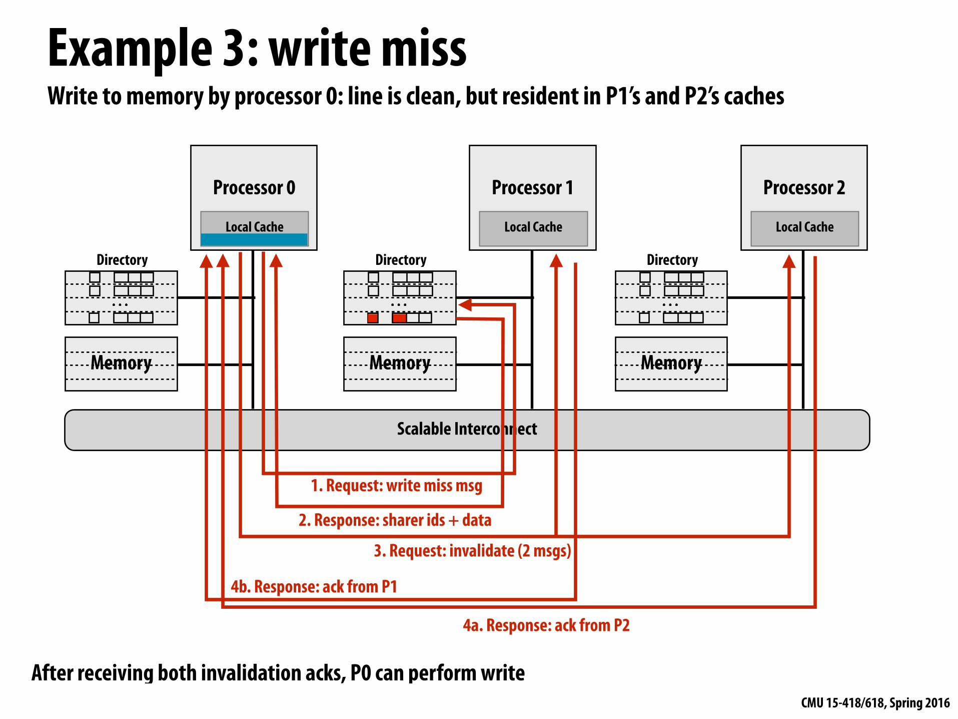
Write to memory by processor 0: line is clean, but resident in P1’s and P2’s caches
1. Request: write miss msg
Scalable Interconnect
CMU 15-418/618, Spring 2016
Example 3: write miss
Processor 0
Local Cache
Memory
Directory
. . .
Processor 1
Local Cache
Memory
Directory
. . .
Processor 2
Local Cache
Memory
Directory
. . .
Write to memory by processor 0: line is clean, but resident in P1’s and P2’s caches
1. Request: write miss msg
2. Response: sharer ids + data
Scalable Interconnect

CMU 15-418/618, Spring 2016
Example 3: write miss
Processor 0
Local Cache
Memory
Directory
. . .
Processor 1
Local Cache
Memory
Directory
. . .
Processor 2
Local Cache
Memory
Directory
. . .
Write to memory by processor 0: line is clean, but resident in P1’s and P2’s caches
1. Request: write miss msg
3. Request: invalidate (2 msgs)2. Response: sharer ids + data
Scalable Interconnect
CMU 15-418/618, Spring 2016
Example 3: write miss
Scalable Interconnect
Processor 0
Local Cache
Memory
Directory
. . .
Processor 1
Local Cache
Memory
Directory
. . .
Processor 2
Local Cache
Memory
Directory
. . .
Write to memory by processor 0: line is clean, but resident in P1’s and P2’s caches
1. Request: write miss msg
3. Request: invalidate (2 msgs)
2. Response: sharer ids + data
4a. Response: ack from P2
4b. Response: ack from P1
After receiving both invalidation acks, P0 can perform write
CMU 15-418/618, Spring 2016
Advantage of directories▪ On reads, directory tells requesting node exactly where to get
the line from - Either from home node (if the line is clean) - Or from the owning node (if the line is dirty) - Either way, retrieving data involves only point-to-point communication
▪ On writes, the advantage of directories depends on the number of sharers - In the limit, if all caches are sharing data, all caches must be
communicated with (just like broadcast in a snooping protocol)

CMU 15-418/618, Spring 2016
Cache invalidation patterns64 processor system
Barnes-Hut
LU
Ocean
0 1 2 3 4 5 6 7
8 to 1
1
12 to
15
16 to
19
20 to
23
24 to
27
28 to
31
32 to
35
36 to
39
40 to
43
44 to
47
48 to
51
52 to
55
56 to
59
60 to
63
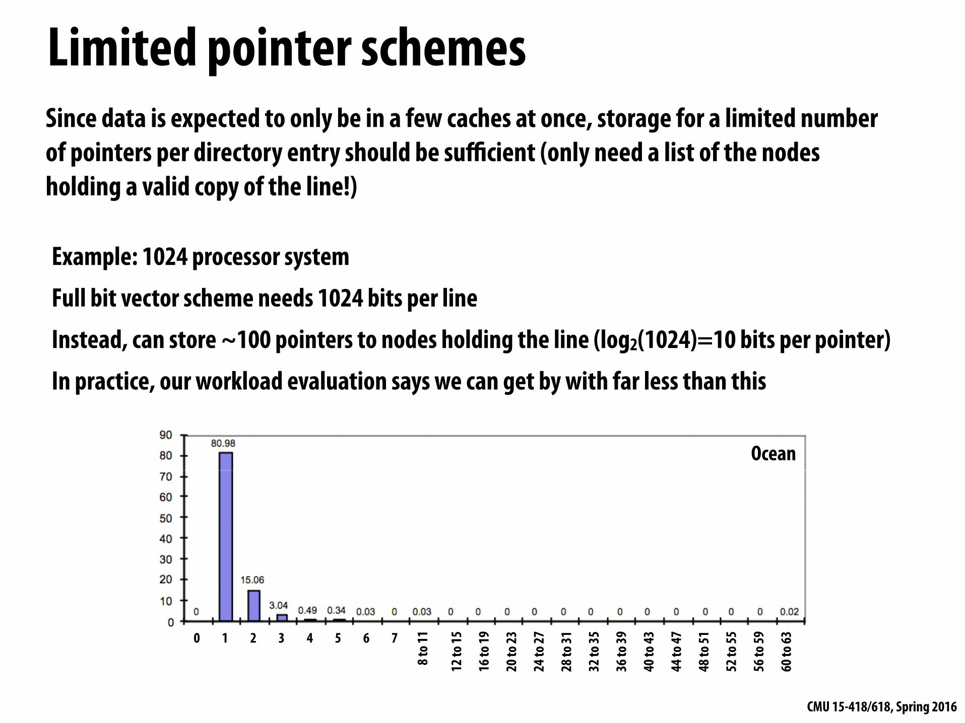
Graphs plot histogram of number of sharers of a line at the time of a write
In general only a few processors share the line (only a few processors must be told of writes)
Not shown here, but the expected number of sharers typically increases slowly with P (good!)

CMU 15-418/618, Spring 2016
In general, only a few sharers during a write ▪ Access patterns
- “Mostly-read” objects: lots of sharers but writes are infrequent, so minimal impact on performance (e.g., root node in Barnes-Hut)
- Migratory objects (one processor reads/writes for while, then another, etc.): very few sharers, count does not scale with number of processors
- Frequently read/written objects: frequent invalidations, but sharer count is low because count cannot build up in short time between invalidations (e.g, shared task queue)
- Low-contention locks: infrequent invalidations, no performance problem - High-contention locks: can be a challenge, because many readers present when lock released
▪ Implication 1: directories are useful for limiting coherence traffic - Don’t need a broadcast mechanism to “tell everyone”
▪ Implication 2: suggests ways to optimize directory implementations (reduce storage overhead)

CMU 15-418/618, Spring 2016
Very simple directory storage requirements
Scalable Interconnect
Processor
Local Cache
Directory
Memory
. . .
One cache line of memory
One directory entry per cache line of memory
P presence bits: indicate whether processor P has line in its cache
Dirty bit: indicates line is dirty in one of the processors’ caches
Assume 64 bytes / cache line P = 256 processors M = main memory size (bytes)
How big is directory?

CMU 15-418/618, Spring 2016
Full bit vector directory representation▪ Recall: one presence bit per node
▪ Storage proportional to P x M - P = number of nodes (e.g., processors) - M = number of lines in memory
▪ Storage overhead rises with P - Assume 64 byte cache line size (512 bits) - 64 nodes (P=64) →12% overhead - 256 nodes (P=256) → 50% overhead - 1024 nodes (P=1024) → 200% overhead
. . .
P
M
. . .

CMU 15-418/618, Spring 2016
Reducing storage overhead of directory▪ Optimizations on full-bit vector scheme
- Increase cache line size (reduce M term) - What are possible problems with this approach?
(consider graphs from last lecture)
- Group multiple processors into a single directory “node” (reduce P term) - Need only one directory bit per node, not one bit per processor - Hierarchical: could use snooping protocol to maintain coherence among
processors in a node, directory across nodes
▪ We will now discuss two alternative schemes - Limited pointer schemes (reduce P) - Sparse directories
CMU 15-418/618, Spring 2016
Limited pointer schemesSince data is expected to only be in a few caches at once, storage for a limited number of pointers per directory entry should be sufficient (only need a list of the nodes holding a valid copy of the line!)
Ocean
Example: 1024 processor system Full bit vector scheme needs 1024 bits per line Instead, can store ~100 pointers to nodes holding the line (log2(1024)=10 bits per pointer) In practice, our workload evaluation says we can get by with far less than this
0 1 2 3 4 5 6 7
8 to 1
1
12 to
15
16 to
19
20 to
23
24 to
27
28 to
31
32 to
35
36 to
39
40 to
43
44 to
47
48 to
51
52 to
55
56 to
59
60 to
63
CMU 15-418/618, Spring 2016
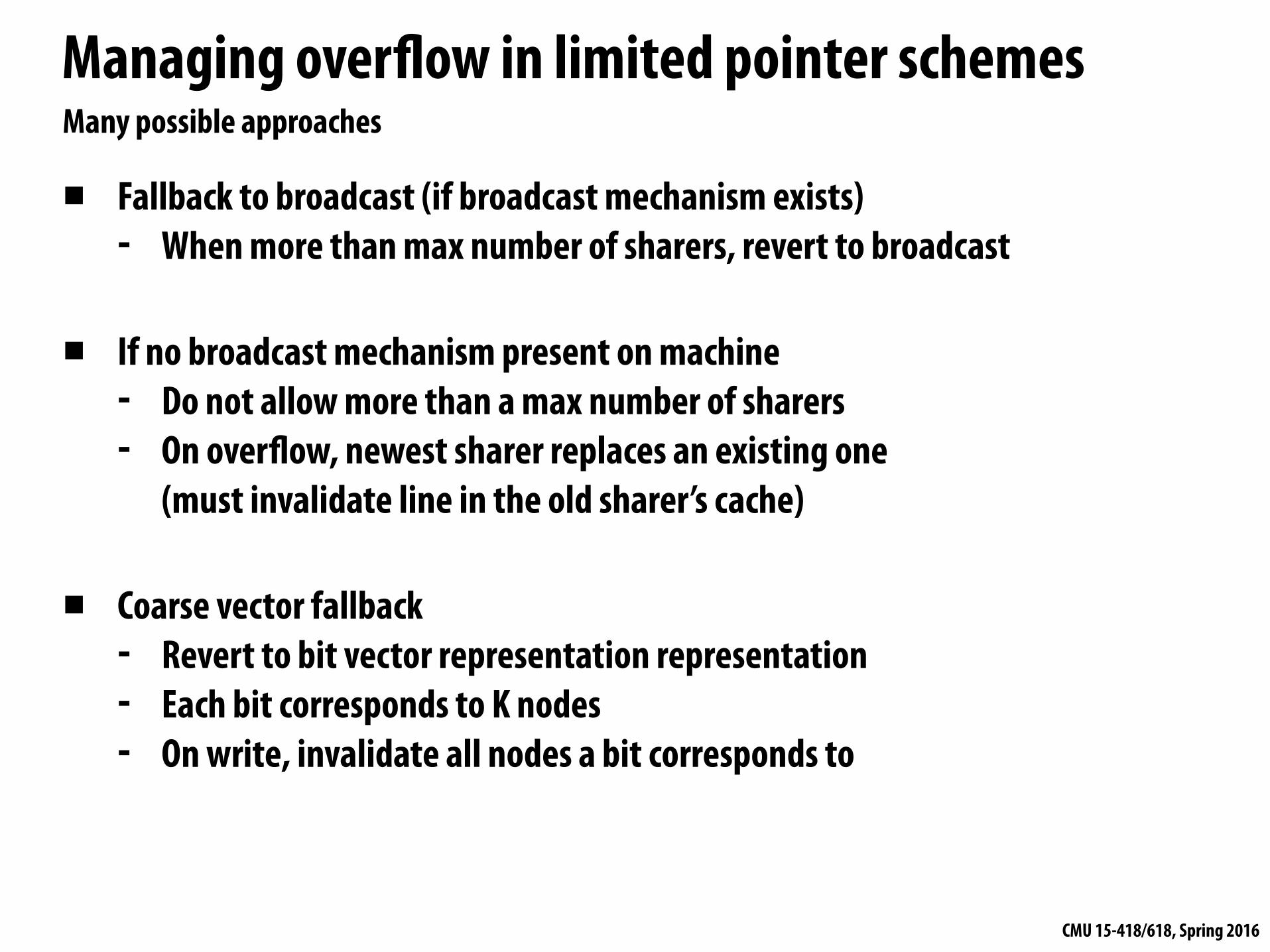
Managing overflow in limited pointer schemes
▪ Fallback to broadcast (if broadcast mechanism exists) - When more than max number of sharers, revert to broadcast
▪ If no broadcast mechanism present on machine - Do not allow more than a max number of sharers - On overflow, newest sharer replaces an existing one
(must invalidate line in the old sharer’s cache)
▪ Coarse vector fallback - Revert to bit vector representation representation - Each bit corresponds to K nodes - On write, invalidate all nodes a bit corresponds to
Many possible approaches
CMU 15-418/618, Spring 2016
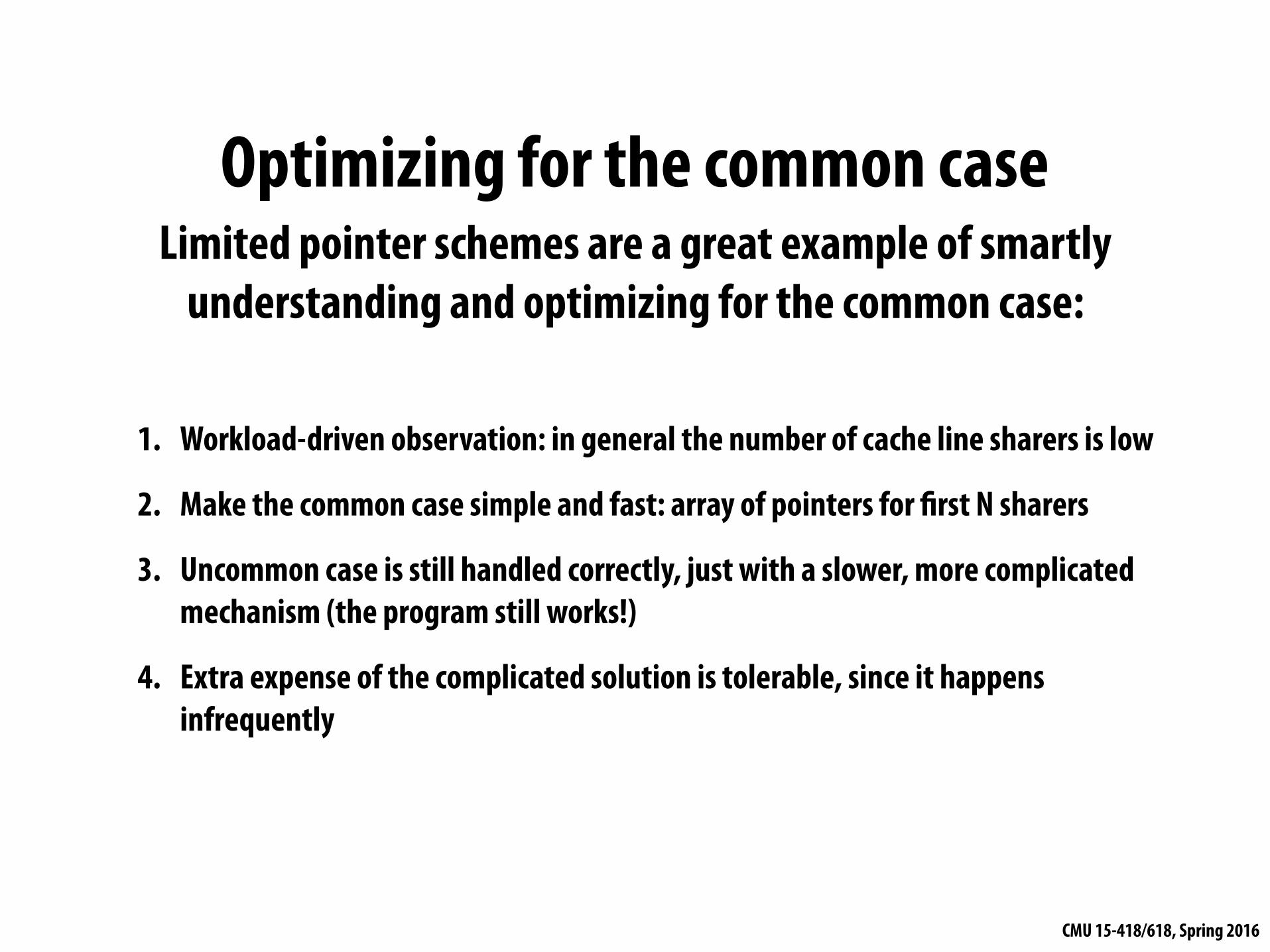
Optimizing for the common caseLimited pointer schemes are a great example of smartly
understanding and optimizing for the common case:
1. Workload-driven observation: in general the number of cache line sharers is low
2. Make the common case simple and fast: array of pointers for first N sharers
3. Uncommon case is still handled correctly, just with a slower, more complicated mechanism (the program still works!)
4. Extra expense of the complicated solution is tolerable, since it happens infrequently
CMU 15-418/618, Spring 2016
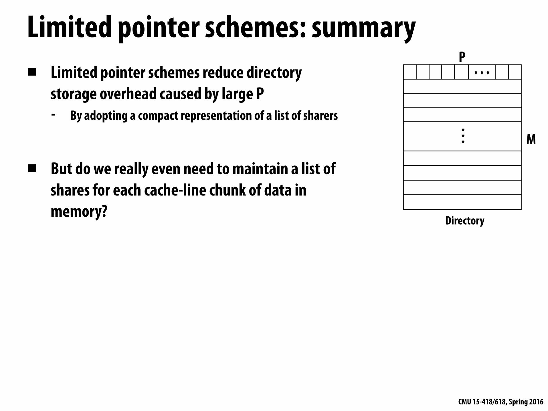
Limited pointer schemes: summary▪ Limited pointer schemes reduce directory
storage overhead caused by large P - By adopting a compact representation of a list of sharers
▪ But do we really even need to maintain a list of shares for each cache-line chunk of data in memory?
. . .
P
M
. . .
Directory

CMU 15-418/618, Spring 2016
Limiting size of directory: sparse directories▪ Key observation: the majority of memory is NOT resident in
cache. And to carry out coherence protocol the system only needs sharing information for lines that are currently in cache - Most directory entries are empty most of the time - E.g., 1 MB cache, 1 GB memory→
- Single node system: ≥ 99.9% of directory entries are empty
▪ How about:
Directory
. . .
One directory entry per cache line of memory
held in some cacheTag
{Tag
Would not scale!

CMU 15-418/618, Spring 2016
Sparse directoriesDirectory at home node maintains pointer to only one node caching line (not a list of sharers) Pointer to next node in list is stored as extra information in the cache line (just like the line’s tag, dirty bits, etc)
. . .M
Processor cache: node 0 (last reader)
prev ptr
line data
Directory (home node for line)
Processor cache: node 1
next ptr
Processor cache: node 2 (last reader)
On read miss: add requesting node to head of list
On write miss: propagate invalidations along list On evict: need to patch up list (linked list removal)
One directory entry per cache line of memory held in some cache

CMU 15-418/618, Spring 2016
Sparse directories: scaling propertiesGood:
- Low memory storage overhead (one pointer to list head per line) - Additional directory storage is proportional to cache size (the list
stored in SRAM) - Traffic on write is still proportional to number of sharers
. . .M
Processor cache: node 0
prev ptr
line data
Directory (home node for line)
Processor cache: node 1
next ptr
Processor cache: node 2
Bad: - Latency of write proportional to number of sharers
(invalidation of lines is serial) - Higher implementation complexity

CMU 15-418/618, Spring 2016
Recall: write miss in full bit vector scheme
Processor 0
Local Cache
Memory
Directory
. . .
Processor 1
Local Cache
Memory
Directory
. . .
Processor 2
Local Cache
Memory
Directory
. . .
Write to memory by processor 0: line is clean, but resident in P1’s and P2’s caches
1. Request: write miss msg
3. Request: invalidate (2 msgs)2. Response: sharer ids + data
Original bit-vector scheme sends same number of invalidation messages as sparse directory approach, but invalidation messages can be sent to
all processors in parallel
Scalable Interconnect

CMU 15-418/618, Spring 2016
Optimizing directory-based coherence
▪ Reducing storage overhead of directory data structure - Limited pointer schemes - Sparse directories
▪ Reducing number of messages sent to implement coherence protocol
CMU 15-418/618, Spring 2016
Memory
Processor 0
Local Cache
Memory
Directory
. . .
Processor 1
Local Cache
Directory
. . .
Processor 2
Local Cache
Memory
Directory
. . .
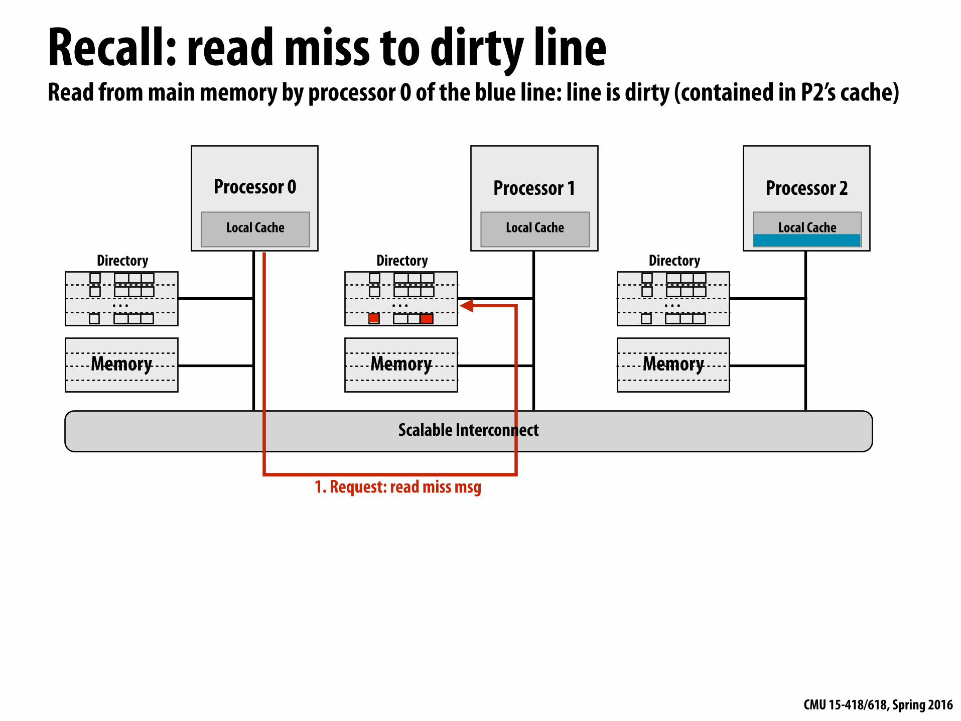
Read from main memory by processor 0 of the blue line: line is dirty (contained in P2’s cache)
1. Request: read miss msg
Recall: read miss to dirty line
Scalable Interconnect

CMU 15-418/618, Spring 2016
Memory
Recall: read miss to dirty line
Processor 0
Local Cache
Memory
Directory
. . .
Processor 1
Local Cache
Directory
. . .
Processor 2
Local Cache
Memory
Directory
. . .
Read from main memory by processor 0 of the blue line: line is dirty (contained in P2’s cache) (Note: figure below shows final state of system after operation is complete)
Five network transactions in total Four of the transactions are on the “critical path” (transactions 4 and 5 can be done in parallel)
- Critical path: sequence of dependent operations that must occur to complete operation
2. Response: owner id
1. Request: read miss msg
3. Request: data4. Response: data
5. Response: data+dir revision
Scalable Interconnect

CMU 15-418/618, Spring 2016
Memory
Intervention forwarding
Processor 0
Local Cache
Memory
Directory
. . .
Processor 1
Local Cache
Directory
. . .
Processor 2
Local Cache
Memory
Directory
. . .
Read from main memory by processor 0 of the blue line: line is dirty (contained in P2’s cache)
1. Request: read miss msg
3. Response: data+dir revision
2. Request: intervention read
2. Home node requests data from owner node (processor 2) 3. Owning node responds
Scalable Interconnect

CMU 15-418/618, Spring 2016
Memory
Intervention forwarding
Processor 0
Local Cache
Memory
Directory
. . .
Processor 1
Local Cache
Directory
. . .
Processor 2
Local Cache
Memory
Directory
. . .
Read from main memory by processor 0 of the blue line: line is dirty (contained in P2’s cache)
1. Request: read miss msg
3. Response: data+dir revision
2. Request: intervention read
4. Response: data
4. Home node updates directory, and responds to requesting node with dataFour network transactions in total (less traffic) But all four of the transactions are on the “critical path.” Can we do better?
Scalable Interconnect
CMU 15-418/618, Spring 2016
Memory
Request forwarding
Processor 0
Local Cache
Memory
Directory
. . .
Processor 1
Local Cache
Directory
. . .
Processor 2
Local Cache
Memory
Directory
. . .
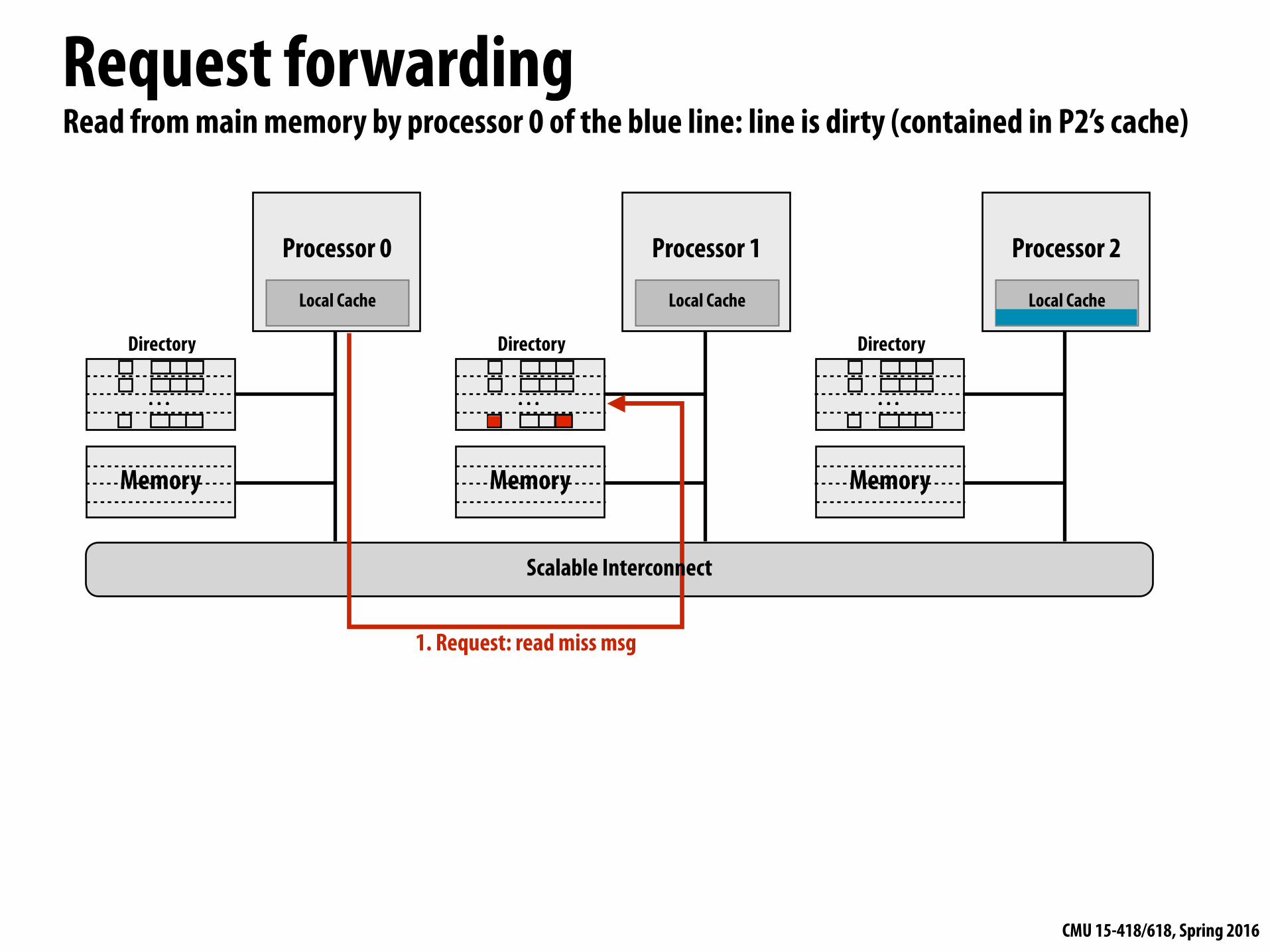
Read from main memory by processor 0 of the blue line: line is dirty (contained in P2’s cache)
1. Request: read miss msg
Scalable Interconnect

CMU 15-418/618, Spring 2016
Memory
Request forwarding
Processor 0
Local Cache
Memory
Directory
. . .
Processor 1
Local Cache
Directory
. . .
Processor 2
Local Cache
Memory
Directory
. . .
Read from main memory by processor 0 of the blue line: line is dirty (contained in P2’s cache)
1. Request: read miss msg 2. Request: send data to requestor
3/4. Response: data (2 msgs: sent to both home node and requestor)
Four network transactions in total Only three of the transactions are on the critical path (transactions 3 and 4 can be done in parallel) Note: system is no longer pure request/response (since P0 sent request to P1, but receives response from P2)
Scalable Interconnect
CMU 15-418/618, Spring 2016
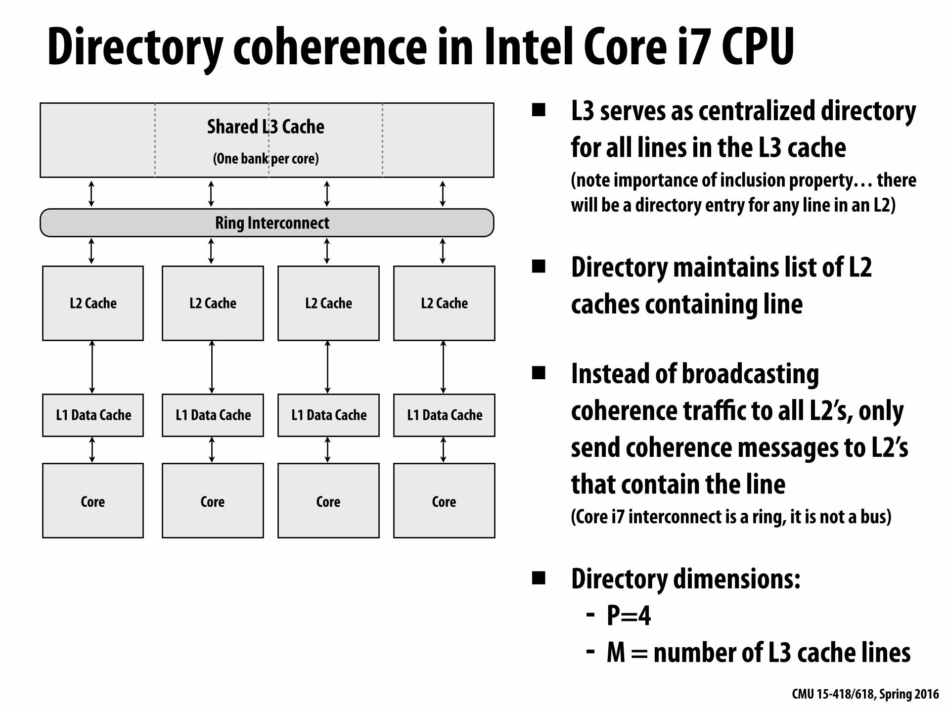
Directory coherence in Intel Core i7 CPU▪ L3 serves as centralized directory
for all lines in the L3 cache (note importance of inclusion property… there will be a directory entry for any line in an L2)
▪ Directory maintains list of L2 caches containing line
▪ Instead of broadcasting coherence traffic to all L2’s, only send coherence messages to L2’s that contain the line (Core i7 interconnect is a ring, it is not a bus)
▪ Directory dimensions: - P=4 - M = number of L3 cache lines
Core
L1 Data Cache
L2 Cache
Shared L3 Cache (One bank per core)
Ring Interconnect
Core
L1 Data Cache
L2 Cache
Core
L1 Data Cache
L2 Cache
Core
L1 Data Cache
L2 Cache

CMU 15-418/618, Spring 2016
Coherence in multi-socket Intel systems
Core
L1
L2
L3 Cache
Core
L1
L2
Core
L1
L2
Core
L1
L2
Core
L1
L2
L3 Cache
Core
L1
L2
Core
L1
L2
Core
L1
L2
Cache Agent Cache Agent
Memory Controller Memory Controller
Home Agent Home AgentQuickPath Interconnect
(QPI)
to DRAM… (with in memory directory)
Dir cache (16KB) Dir cache (16KB)
to DRAM… (in memory directory)
▪ L3 directory reduces on-chip coherence traffic (previous slide)
▪ In-memory directory (cached by home agent/memory controller) reduces coherence traffic between cores
CMU 15-418/618, Spring 2016
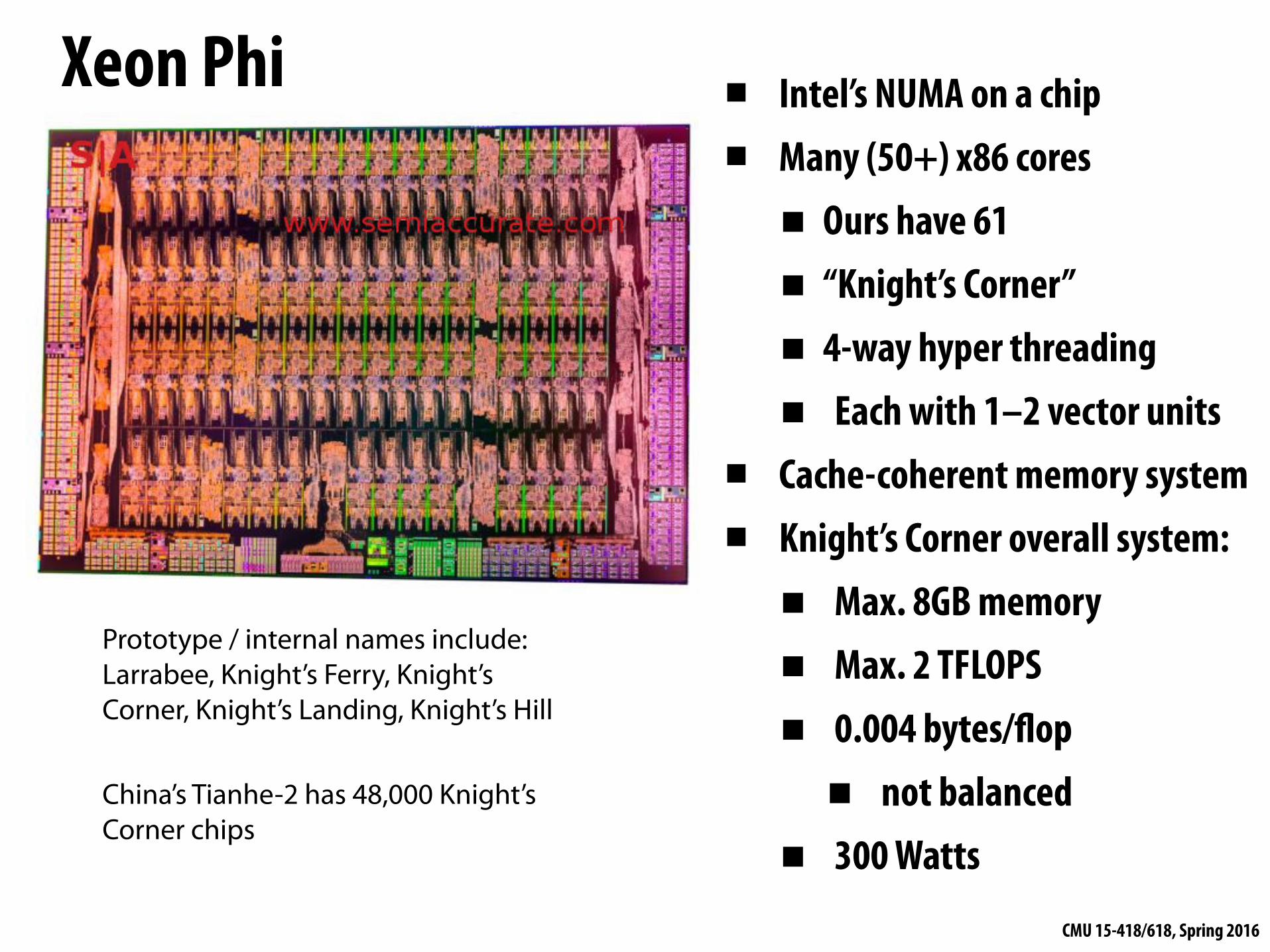
Xeon Phi ▪ Intel’s NUMA on a chip ▪ Many (50+) x86 cores
▪ Ours have 61
▪ “Knight’s Corner”
▪ 4-way hyper threading
▪ Each with 1–2 vector units ▪ Cache-coherent memory system ▪ Knight’s Corner overall system:
▪ Max. 8GB memory
▪ Max. 2 TFLOPS
▪ 0.004 bytes/flop
▪ not balanced
▪ 300 Watts
Prototype / internal names include: Larrabee, Knight’s Ferry, Knight’s Corner, Knight’s Landing, Knight’s Hill
China’s Tianhe-2 has 48,000 Knight’s Corner chips
CMU 15-418/618, Spring 2016
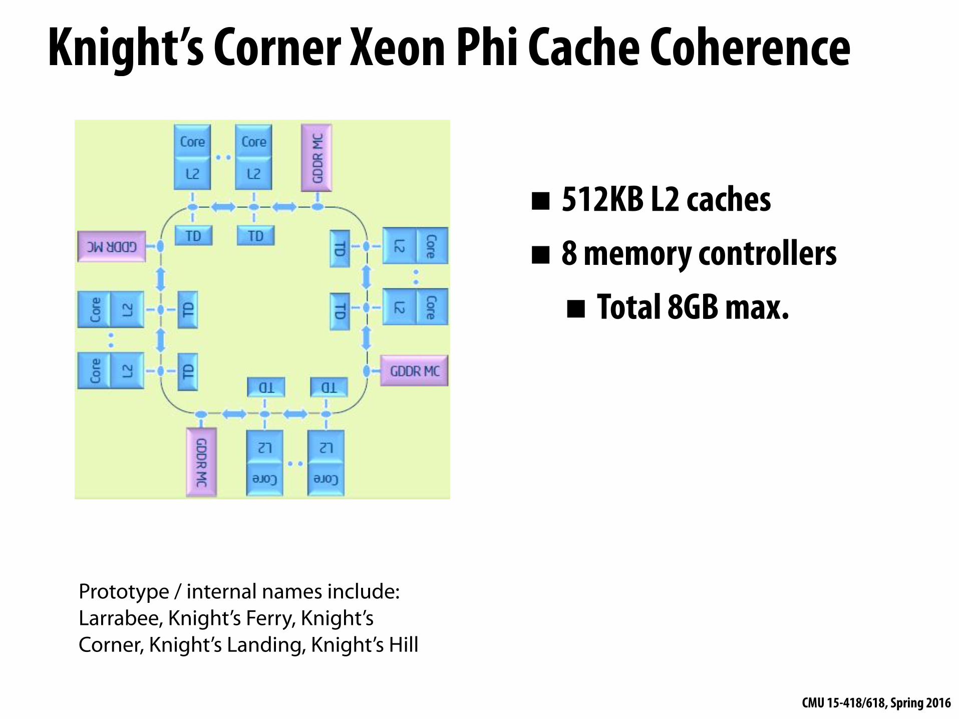
Knight’s Corner Xeon Phi Cache Coherence
▪ 512KB L2 caches
▪ 8 memory controllers
▪ Total 8GB max.
Prototype / internal names include: Larrabee, Knight’s Ferry, Knight’s Corner, Knight’s Landing, Knight’s Hill
CMU 15-418/618, Spring 2016
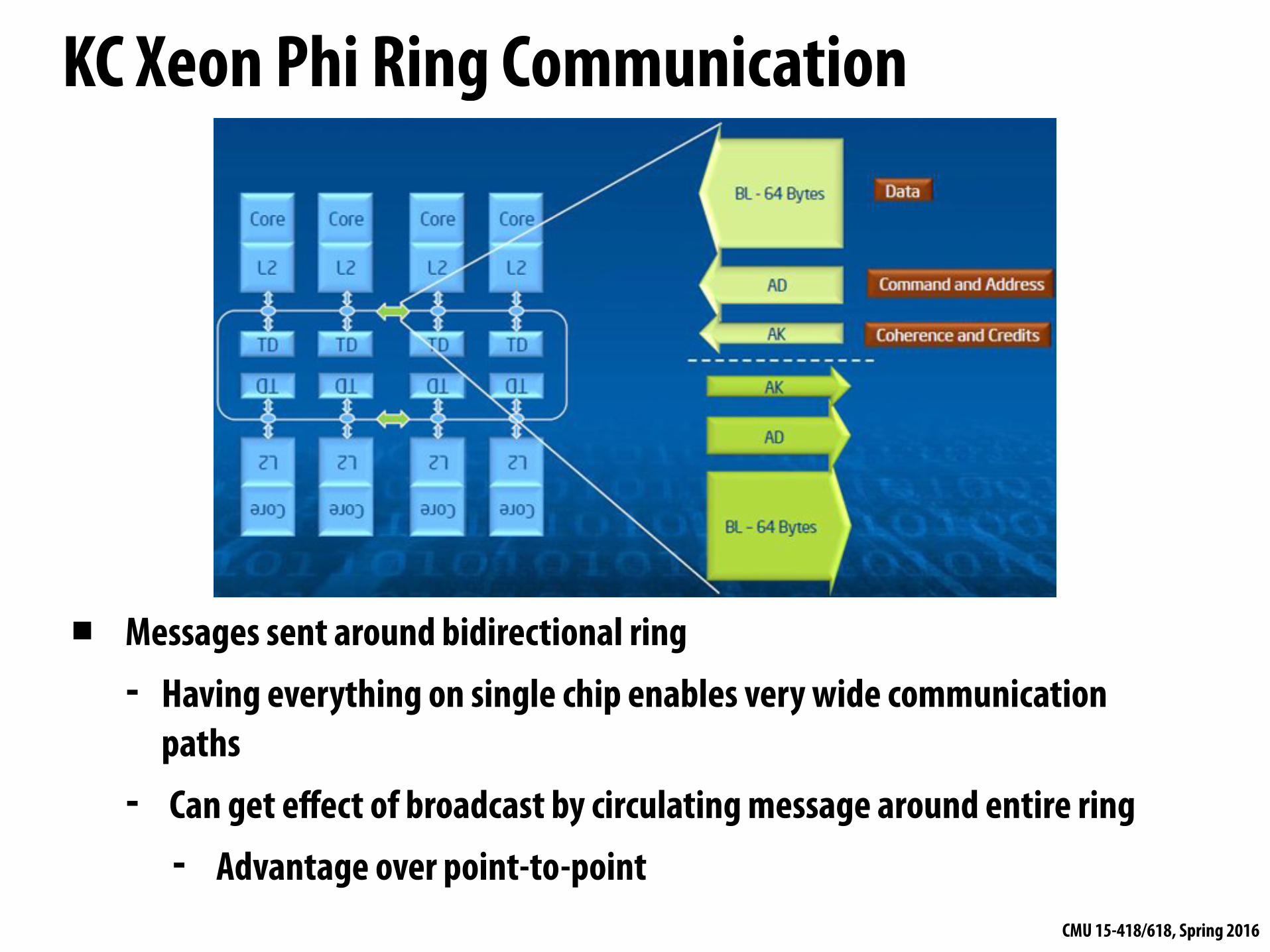
KC Xeon Phi Ring Communication
▪ Messages sent around bidirectional ring - Having everything on single chip enables very wide communication
paths - Can get effect of broadcast by circulating message around entire ring
- Advantage over point-to-point

CMU 15-418/618, Spring 2016
KC Xeon Phi Directory Structure
▪ Directory keeps track of which lines are resident in local L2 - Same as with single-node system
▪ Worst-case memory read or write by P: 1. Check local cache 2. Circulate request around ring for line in some cache 3. Send request around ring to memory controller

CMU 15-418/618, Spring 2016
Next Generation Xeon Phi▪ “Knight’s Landing” ▪ 72 cores
▪ Each with 4-way hyper threading
▪ Each with 2 vector units ▪ Grouped into pairs to give 36
compute nodes ▪ Peak 6 SP TFLOPS ▪ 16 GB on package RAM ▪ Access to up to 384 GB off-
package RAM

CMU 15-418/618, Spring 2016
Knight’s Landing Xeon Phi Cache Coherence
▪ Nodes organized as 2-D mesh
▪ Some for computation
▪ Some for memory interfaces
▪ Use X/Y routing to send messages
▪ Must use more traditional directory-based scheme

CMU 15-418/618, Spring 2016
Summary: directory-based coherence▪ Primary observation: broadcast doesn’t scale, but luckily we don’t need to
broadcast to ensure coherence because often the number of caches containing a copy of a line is small
▪ Instead of snooping, just store the list of sharers in a “directory” and check the list as necessary
▪ One challenge: reducing overhead of directory storage - Use hierarchies of processors or larger line sizes - Limited pointer schemes: exploit fact the most processors not sharing line - Sparse directory schemes: exploit fact that most lines are not in cache
▪ Another challenge: reducing the number of messages sent (traffic) and critical path (latency) of message chains needed to implement coherence operations
▪ Ring-based schemes can be much simpler than point-to-point communication