"load history and buckling of the production casing in a...
TRANSCRIPT

PROCEEDINGS, Thirty-Sixth Workshop on Geothermal Reservoir Engineering Stanford University, Stanford, California, January 31 - February 2, 2011 SGP-TR-191
LOAD HISTORY AND BUCKLING OF THE PRODUCTION CASING IN A HIGH TEMPERATURE GEOTHERMAL WELL
Gunnar Skúlason Kaldal1*, Magnús Þ. Jónsson1, Halldór Pálsson1, Sigrún N. Karlsdóttir2, Ingólfur Ö.
Þorbjörnsson2,3
1Faculty of Industrial Engineering, Mechanical Engineering and Computer Science, University of Iceland, Hjarðarhagi 2-6, Reykjavik, 107, Iceland
2 Innovation Center Iceland, Department of Materials, Biotechnology and Energy, Keldnaholt, Reykjavik, 112, Iceland
3Reykjavik University, Menntavegur 1, Reykjavik, 101, Iceland *e-mail: [email protected]
ABSTRACT
The production casing of a high temperature geothermal well is subjected to multiple thermo-mechanical loads in the period from installation to production. Temperature and pressure fluctuations are large in high temperature geothermal wells, for example during the first discharge the temperature difference from a non-flowing to a flowing well can be on the range of hundreds of degrees centigrade. During installation, stimulation and production, problems can arise due to these loads and due to a possible corrosive geothermal environment. Plastic buckling of the production casing is a problem that can occur. It results in a bulge in the wall of the casing and is detrimental to the geothermal energy production and the lifetime of the well. The cost of each well is very high. Therefore, it is important to analyze the structural environment of high temperature geothermal wells in effort to avoid repeated problems in the design and installment phases of the casing. A finite-element model has been developed to evaluate the temperature distribution, deformation and stresses in a high temperature geothermal well and to evaluate the reasons for buckling in the production casing. The load history of the casing is followed from the beginning of the installment phase to the production phase. The results show that the load history and also the sequence of loading is important in order to understand the true structural behavior of wells.
INTRODUCTION
Geothermal wells consist of several concentric steel casings and concrete sealant that is in contact with the surrounding rock formation. Plastic buckling of the production casing is a problem that can occur.
The innermost casing, the production casing, buckles and forms a bulge on the inside of the casing wall. This deformation of the casing can lead to reduced energy output and in worst cases render the well inoperative. A number of interesting cases of casing impairments have occurred in Iceland. There exist however some difficulties in tracking the history of the wells. For example the load history of wells is not always fully known, as down hole P-T measurements are often sparse and cannot be performed constantly. Icelandic well drilling, operation and completion reports, from the National Energy Authority and Iceland Geosurvey, were used to gather information and data on the load history and well completion processes. Casing failure as a result of trapped fluid in the casing to casing annulus have been discussed as a suspected cause of casing collapse by for example Björnsson (1978), Magneschi (1995) and Southon (2005). Southon lists casing failure modes in geothermal wells and discusses the importance of ensuring that construction and design techniques are sound and carefully implemented. He also discusses that pre-tension loads need to be determined to avoid compression yielding when using buttress threaded couplings. Euler buckling and helical buckling are addressed by Leaver (1982) where analyses are performed and equations developed for buckling of an uncemented length of casing. Euler buckling is also addressed by Rechard and Schuler (1983) where buckling models are produced. Chiotis and Vrellis (1995) list casing failures observed in Greek wells where wellhead movement, casing joint decoupling, buckling of a 9 5/8 in casing in 6 different places, tieback casing collapse and serious wellhead leakages associated with casing corrosion are discussed. They conclude that the major casing failures observed are caused by thermal stress

and that burst and collapse strengths are severely reduced by axial thermal stress. Kane (1996) evaluates corrosion problems involving in-service failures of geothermal well production casings where high thermally induced tensile stress in combination with the presence of hydrogen sulfide results in sulfide stress cracking. Few finite-element models of wells have been created. A 2D finite element model of the cross section of a double cased geothermal well was created for representing the behavior of the cement/sealant by Philippacopoulos and Berndt (2002) where the results showed the inadequacy of geothermal well design based solely on compressive strength. A plane strain finite element model for well failure due to formation movement and a three dimensional model to analyse the local behavior of the casing-cement-formation interaction in geothermal wells were developed also by Philippacopoulos and Berndt (2000) where the part of the results revealed the importance of the cement properties on the response of the casing patch cement included in the three dimensional model. Peng, Fu and Zhang (2007) created a finite-element model to represent oil-field casing failure in unconsolidated formations where the results showed non-uniform and multi-directional casing deformation. The buckling/bulging of the wall of the casing is presumably a local phenomenon, although the whole well should be considered since forces are transmitted throughout its whole length. A finite-element model has been developed where a section of a high temperature geothermal well is modeled. Boundary conditions are defined to represent the considered outer interaction. The well section is 24 m long and includes three casings, the production casing, the security casing and the outermost surface casing, as well as concrete and the rock formation. Two simplified couplings are included in the production casing in order to observe the effect of increased stress in the concrete near the couplings as well as the inverse effect on the casing. The objective of the analysis is to evaluate the highest risk of production casing wall buckling/bulging with the use of the model. The load history of the casing is tracked from the beginning of the installation of the casing, where the casing is hanging from the top of the well, to the production phase, where the casing has been subjected to high temperature change (possibly cyclic) due to operation on site and stimulation procedures. Tracking the load history is important because the casing can be damaged at various steps, such as in the installment phase, the stimulation process, warming-up periods, discharging of the well and even in the production phase. In addition stress
builds up in the casing and plastic deformation occurs, constantly increasing the risk of instability and casing impairment. In this article, the focus is on wall buckling and collapse of the production casing. Production casing impairment modes and load history are discussed. A finite-element model and a case study is represented and discussed. Finally the results from the model are presented and discussed.
PRODUCTION CASING IMPAIRMENT
Casing failure modes can be classified into (a) buckling failures, (b) coupling failures, (c) tear failures and (d) corrosion failures. Casing failure modes and possible load cases are listed in Table 1. Indications of casing failures are often in limited numbers and casing failure can go unnoticed for a long period, if noticed at all. Casing failures can cause a serious hazard of leakage and blow out risk. For instance in one known example from the 70s, the production casing of a well in northern Iceland was in poor shape due to a highly corrosive environment, eventually causing an immense explosion, leaving a crater where the wellhead once stood (Pálmason 2005). Large wellhead movement and buckling/bulging of the casing suggests compressive forces in the casing due to thermal expansion, whereas body tear and coupling rupture indicate tensional forces that form during casing installment and when the completed well is cooled. Table 1: Casing failure modes and possible load. Casing failure mode Load
Euler buckling +∆T, axial compression
(a) Buckling
Wall buckling +∆T, ∆P, flow problem
Tensional tear -∆T, gravity (b) Coupling Compression thread slip
+∆T, axial compression
(c) Tear Casing body -∆T, gravity After the casing string has been cemented, Euler buckling can occur, where the casing acts as a column, if there is a large enough un-cemented gap in the surrounding annulus allowing a large deflection (Rechard 1983). This can occur if the casing is subjected to compressive axial force for instance during temperature increase. Buckling of the casing wall, where a bulge forms on one side, is a different scenario from Euler buckling. The absolute reason for the bulge deformation is unclear, but possible cause is a combination of various loads and imperfections. Possible imperfections could be a reduced casing wall thickness and the existence of enclosed water or un-cemented gap in the casing to casing annulus due to a

faulty cementing job. Complete collapse of the casing can occur if the pressure difference between the outer and inner wall exceeds the collapse resistance of the casing, for example during cementing. High axial tension forces, for instance when negative temperature change occurs, can lead to coupling failures and in some instances casing body tear. When the casing depth is large and imperfections are present, the weight of an uncemented casing can cause a casing body tear or coupling failure in worst case scenario. Axial compression, for example due to increase in temperature, can cause a thread slip in the coupling area. Corrosion can cause serious production casing failures. It can be very different between geothermal regions and even different within a geothermal region, for example from well to well or varying with depth. For H2S rich environments sulfide stress cracking (SSC) and hydrogen embrittlement can cause problems depending on the material selection for the steel casing (Kane 1996). Other forms of corrosion, for example uniform corrosion, erosion, and cavitation can exist in geothermal wells. No general solution for corrosion in geothermal wells exists and each case should be treated separately.
PRODUCTION CASING LOAD HISTORY
Here the load history of the production casing is tracked from the installment phase to the production phase. The possible load cases considered occur at various phases, i.e. the (i) installation of the production casing, (ii) stimulation of the well, (iii) discharge of the well, and (iv) production.
Figure 1: Production casing loads.
(i) Installation of the production casing The discussed load cases are summarized in Table 2. During the installation of the production casing, casing components are screwed together and lowered
down into the well one by one. The first load on the casing, load case 1, is tensional force due to gravity, see diagram A in Figure 1. The tension increases with increased depth, putting the highest strain on the last installed casing component that supports the whole casing before the concrete sets. While the casing is being installed, the well is kept full of cold water, which provides a buoyant force. Table 2: Considered load cases. Load case
Description Load
(i) Installation of the production casing 1 Casing hanging
from the top of the well.
Gravity.
2 Cement slurry in place.
Outer pressure from cement slurry + pumping pressure.
3 Concrete setting. Temperature increase due to heat of hydration and well surroundings.
4 Production section of the well drilled with cooling fluid.
Temperature decrease due to cooling fluid.
(ii) Stimulation of the well 5a-i Warm-up period. Temperature
increases. 5a-ii Cooling, water is
pumped into the well.
Temperature decreases due to cold water.
5b Rock fractured with pressurized water.
Temperature decreases, pressure inside the well.
5c Fracture cleaning with acid.
Can cause corrosion if it comes in contact with the casing.
5d Rock fractured locally by burning rocket-fuel.
No load subjected on production casing.
(iii) Discharge of the well 6a Water column lifted
with air bubbles through drill-string.
Temperature increase, small pressure de-crease,
6b Water column pushed down and released quickly
Rapid depressurization and temperature increase
(iv) Production 7 Harmful flow
regimes. Local dynamic pressure change.
If centralizers are taken into account as a weight relieving force, the relieving force has to be roughly estimated. This is due to friction between the centralizers and the outer steel casing wall and the formation below the outer casing shoe.
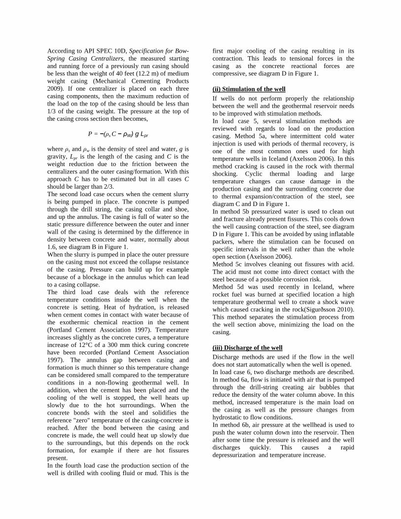
According to API SPEC 10D, Specification for Bow-Spring Casing Centralizers, the measured starting and running force of a previously run casing should be less than the weight of 40 feet (12.2 m) of medium weight casing (Mechanical Cementing Products 2009). If one centralizer is placed on each three casing components, then the maximum reduction of the load on the top of the casing should be less than 1/3 of the casing weight. The pressure at the top of the casing cross section then becomes,
P = −(ρs C − ρW) g Lpr where ρs and ρw is the density of steel and water, g is gravity, Lpr is the length of the casing and C is the weight reduction due to the friction between the centralizers and the outer casing/formation. With this approach C has to be estimated but in all cases C should be larger than 2/3. The second load case occurs when the cement slurry is being pumped in place. The concrete is pumped through the drill string, the casing collar and shoe, and up the annulus. The casing is full of water so the static pressure difference between the outer and inner wall of the casing is determined by the difference in density between concrete and water, normally about 1.6, see diagram B in Figure 1. When the slurry is pumped in place the outer pressure on the casing must not exceed the collapse resistance of the casing. Pressure can build up for example because of a blockage in the annulus which can lead to a casing collapse. The third load case deals with the reference temperature conditions inside the well when the concrete is setting. Heat of hydration, is released when cement comes in contact with water because of the exothermic chemical reaction in the cement (Portland Cement Association 1997). Temperature increases slightly as the concrete cures, a temperature increase of 12°C of a 300 mm thick curing concrete have been recorded (Portland Cement Association 1997). The annulus gap between casing and formation is much thinner so this temperature change can be considered small compared to the temperature conditions in a non-flowing geothermal well. In addition, when the cement has been placed and the cooling of the well is stopped, the well heats up slowly due to the hot surroundings. When the concrete bonds with the steel and solidifies the reference "zero" temperature of the casing-concrete is reached. After the bond between the casing and concrete is made, the well could heat up slowly due to the surroundings, but this depends on the rock formation, for example if there are hot fissures present. In the fourth load case the production section of the well is drilled with cooling fluid or mud. This is the
first major cooling of the casing resulting in its contraction. This leads to tensional forces in the casing as the concrete reactional forces are compressive, see diagram D in Figure 1.
(ii) Stimulation of the well If wells do not perform properly the relationship between the well and the geothermal reservoir needs to be improved with stimulation methods. In load case 5, several stimulation methods are reviewed with regards to load on the production casing. Method 5a, where intermittent cold water injection is used with periods of thermal recovery, is one of the most common ones used for high temperature wells in Iceland (Axelsson 2006). In this method cracking is caused in the rock with thermal shocking. Cyclic thermal loading and large temperature changes can cause damage in the production casing and the surrounding concrete due to thermal expansion/contraction of the steel, see diagram C and D in Figure 1. In method 5b pressurized water is used to clean out and fracture already present fissures. This cools down the well causing contraction of the steel, see diagram D in Figure 1. This can be avoided by using inflatable packers, where the stimulation can be focused on specific intervals in the well rather than the whole open section (Axelsson 2006). Method 5c involves cleaning out fissures with acid. The acid must not come into direct contact with the steel because of a possible corrosion risk. Method 5d was used recently in Iceland, where rocket fuel was burned at specified location a high temperature geothermal well to create a shock wave which caused cracking in the rock(Sigurðsson 2010). This method separates the stimulation process from the well section above, minimizing the load on the casing.
(iii) Discharge of the well Discharge methods are used if the flow in the well does not start automatically when the well is opened. In load case 6, two discharge methods are described. In method 6a, flow is initiated with air that is pumped through the drill-string creating air bubbles that reduce the density of the water column above. In this method, increased temperature is the main load on the casing as well as the pressure changes from hydrostatic to flow conditions. In method 6b, air pressure at the wellhead is used to push the water column down into the reservoir. Then after some time the pressure is released and the well discharges quickly. This causes a rapid depressurization and temperature increase.

(iv) Production When the well is in production, harmful flow regimes could result in casing impairment. For example, plug flow can occur when the geothermal fluid boils, which could cause local dynamic pressure changes and cavitation.
FINITE-ELEMENT MODEL
The FE-model is a 3D thermal and structural model. The thermal model calculates the temperature distribution, or rather the temperature change from the reference cementing conditions. The reference conditions (or zero condition) for the model is where the concrete sets and forms a connection to the steel casings. The temperature distribution is first calculated through all casings, concrete and the surrounding rock formation. The solution from the thermal model is then used as a load for the structural model.
Figure 2: Element model geometry. As mentioned before two couplings are included in the production casing. For simplification, the couplings are modeled as a solid body with no threads included. The couplings are included to see the steel-concrete interaction assuming no thread-slip in the coupling. For better efficiency half of the well is modeled, which is possible because of symmetry. Three casings are included, a 13 3/8 in (outer diameter) and 12.2 mm (0.48 in) thick production casing, 18 5/8 in and 13 mm (0.51 in) thick security casing and a 22 1/2 in also 13 mm (0.51 in) thick surface casing. Figure 2 shows the model geometry and the included coupling. Imperfections are included in the concrete as a small variation in material properties. These variations are shown as yellow elements.
Figure 3: The coupling of the production casing and the surrounding concrete (transparent).
Material properties are defined separately for the steel, the concrete and the ground, see Table 3. The reference value for the compressive strength of the concrete is 27.6 MPa. Stress-strain behavior of K55 is used in the model for all three casings. In the model four different stress-strain curves can be used for the steel. Defined steel grades for K55, X56, L80 and T95 were obtained from tensile strength tests by Karlsdottir (Karlsdóttir 2009). Table 3: Reference values, material properties used
in the FE-analysis. Steel Concrete Rock Young's modulus (E)
210 GPa 2,8 GPa 100 GPa
Poisson's ratio (γ) 0.3 0.15 0.31 Density (ρ) 7850
kg/m3 1666 kg/m3
2650 kg/m3
Thermal conductivity (K)
46 W/(m°C)
0.81 W/(m°C)
2 W/(m°C)
Thermal expansion (α)
12e-6 /°C 9e-6 /°C 5.4e-6 /°C
The bonding characteristics between steel and concrete are one of the reasons for the numerical complexity of the model. During the solution process, the contact between the casing and the concrete is constantly changing from bonded to sliding to sticking to debonding. This makes the problem extremely complicated and computation time becomes considerably large. Maximum surface shear strength (Wallevik 2009) between the steel casing and the concrete, before debonding occurs, is used in the analysis. When the friction stress reaches the maximum shear strength, the bond is broken and sliding begins. Furthermore, a maximum normal contact stress is used to control the debonding characteristics.

CASE STUDIES
A load history case of the production casing is extracted from the load cases presented in the "Production casing Load history" section. The load history is put together with load cases 1-4, 5a-i, 5a-ii and 6a from Table 2. This particular case is supposed to represent a general load history of a typical well, although the load history for each high temperature geothermal well is unique. K55 steel in used in all casings and the material properties seen in Table 3 are used. In another case, high positive temperature difference is applied on the casing to see at what temperature the casing buckles. To see the effect of enclosed water in the concrete, two cases are performed, one where a small water pocket is included in the analysis and one without it. A temperature change of 750°C and inside pressure of -5 MPa is applied on the casing in both cases. A small water pocket is included in the analysis, 1,6 m long, filling up half of the annulus circumference. Imperfections are randomly dispersed in the domain, consisting of 80% water and 20% concrete.
Figure 4: Water pocket in concrete (cyan colored),
(production casing is transparent).
RESULTS
Load history results In the following load cases, assumed temperature changes and pressure are used in the model, based on typical conditions that should be expected in reality. In load cases 1 and 2, only the production casing is modeled. In load case 1, 600m of casing is assumed to be hanging freely below the modeled section. In load case 2, a cement slurry pressure of 0.6 MPa is subjected on the casing assuming 100 m of concrete
above. In load case 3, all casings, concrete and the rock formation are added to the analysis, where the slurry is assumed to solidify at 50°C which is the reference temperature for the analysis. After bounding of the concrete with the steel, the temperature change is assumed to increase by 50°C because of the heat of hydration and the surroundings. At load case 4, the casing is cooled with cooling fluid, assuming that it reaches temperatures as low as 5°C. In load case 5a-i the casing heats up to 300°C as the well is allowed to heat up during stimulation procedures. In load case 5a-ii the well is cooled down to 5°C again during stimulation procedures. In the last load case the well heats up to production conditions, 350°C, as it is discharged. Table 4 lists the load, temperature change, ∆T, and pressure difference, Pi-o, between the inner and outer wall of the casing, for each load case in the analysis. Table 4: Load for the analysis. Load Case
∆T [°C] (well temp.)
Pi-o [MPa]
Comment
1 - - Gravity of a 600 m casing hanging free.
2 - -0.58 Cement slurry outer pressure on casing.
3 +50 (100) - Heat of hydration and surroundings.
4 -95 (5) - Production section of the well drilled with cooling fluid.
5a-i +295 (300) - Stimulation, heating period
5a-ii -295 (5) - Stimulation, cooling period
6a +345 (350) - Discharge of the well
Figure 5: The temperature distribution (temperature
difference) of load case 6a.

The temperature distribution solution from the thermal model for load case 6a can be seen in Figure 5. The temperature distribution is then used as a temperature difference load on the structural model. In Table 5 the maximum von Mises stress is listed for the production casing and surrounding concrete for all load cases. The maximum radial displacement of the casing is displayed in Table 6 and the maximum axial displacement of the casing is displayed in Table 7. Table 5: Maximum von Mises stress (MPa).
Steel Casing Concrete Load Case Value Location Value Location 1 31.2 Coupling
border - -
2 97.0 Near coupling
- -
3 160 Coupling border
2.87 Coupling border
4 284 Coupling border
4.96 Coupling border
5a-i 329 Coupling border
30.2 Coupling border
5a-ii 433 Between couplings
15.7 Coupling border
6a 374 Near coupling
34.5 Coupling border
Table 6: Maximum radial displacement of the casing
(mm). Steel Casing Load
Case Value Location 1 -0.00757 Near coupling 2 -0.0638 Near coupling 3 0.136 Near coupling 4 -0.567 Casing body 5a-i 0.726 Near coupling 5a-ii -1.740 Between couplings 6a 0.897 Outer radius Table 7: Maximum axial displacement of the casing
(mm). Steel Casing Load
Case Value Location 1 2.834 At lower end 2 2.798 At lower end 3 -0.0938 Coupling border (inner) 4 0.0583 Coupling border (outer) 5a-i -0.689 Coupling border (inner) 5a-ii -7.77 Between couplings 6a -7.814 Between couplings From these results it can be seen that the casing suffers the highest strain when it is cooled down during the supposed stimulation process in load case
5a-ii. The highest stress in the concrete occurs in warm-up periods at the coupling borders. It is interesting to see that the highest inward radial displacement of the casing occurs during this cooling period.
Figure 6: Stress reduction/increase in couplings in
load case 6a. Near the couplings, the stress increases in the concrete and reduces in the steel couplings, see Figure 6. Since there are no threads included in the couplings in the analysis the coupling failures can not be predicted precisely with this model, but this gives an indication of how the steel and concrete react. Figure 7 shows that debonding of the production casing and concrete is progressing and a small gap is beginning to form, increasing the risk of buckling next time the well is heated up.
Figure 7: Contact gap between casing and concrete
in load case 5a-ii.

The stimulation method where the rock is fractured with cyclic thermal shocking can cause damage to the casing if the difference in temperature is high and if this is done repeatedly.
Buckling Since buckling did not occur in the load history analysis above, a load of a high temperature is subjected on the casing to see at what temperature buckling occurs. Table 8: Maximum stress and displacements - case
without water pocket. Steel casing Maximum Value Location Von Mises stress [MPa] 358 Casing body Radial displacement [mm] 2.20 Near coupling Axial displacement [mm] 1.09 Near coupling Table 9: Maximum stress and displacements at the
buckling point - case with water pocket. Steel casing Maximum Value Location Von Mises stress [MPa] 440 At water pocket Radial displacement [mm] -106 At water pocket Axial displacement [mm] 63.7 At water pocket In the case without the water pocket buckling does not occur despite the high temperature change. The results show that the casing expands radially pushing up against the concrete and causing no debonding from the concrete. The maximum von Mises stress in the concrete is 35.7 MPa at the coupling boundary.
Figure 8: Buckling, radial displacement (meters). In the case including the water pocket, buckling occurs at 40% of the load, i.e. at about 300°C and -2
MPa inside pressure. The maximum stress of the casing reaches the yield strength of the steel at the buckling point and the maximum von Mises stress in the concrete reaches 44 MPa at the boundary of the water pocket. The radial displacement and the buckling shape can be seen in Figure 8.
CONCLUSION
A finite-element model was developed to calculate the stresses in a casing that is subjected to thermo-mechanical loads. The results show that the production casing experiences a peak in stress when the casing is cooled during a supposed stimulation process, whereas the concrete suffers the highest stress during heating periods. The stress in the concrete is increased near the couplings, whereas the inverse occurs in the steel couplings. During cooling periods the casing contracts axially and it is interesting to see how much it contracts radially resulting in debonding between the steel and concrete. This leads to higher risk of buckling when the well heats up again because of reduced support from the concrete, which shows that the load history and the sequence of load cases is important. In addition the load history is important because of cumulative stresses and plastic strains that occur in the casing. The results show buckling when a water pocket is included in the concrete surrounding the production casing, whereas a case without the water pocket shows radial expansion of the casing and no buckling. This shows that a water pocket that is enclosed in the casing-to-casing annulus clearly has an effect on the buckling phenomenon. It is clear that further work needs to be done to gain a better knowledge of how the production casing behaves as a whole in a high temperature geothermal well and to gain a better insight into the failure modes that cause problems. In addition, values for a complete load history of a real failure case would be preferred to use as an input in the model. There are many uncertainties regarding what leads to casing impairment. It is apparent that a combination of factors are causing casing failures, which could include; imperfections and production flaws in casings, casing thickness deviation, ovality of the casing, casing centralization, concrete mix properties, quality of the cementing job, and various loading scenarios. In further work it would also be interesting to compare different casing sizes, the effect of concrete gap or water pocket size on the types of buckling, as well as different stimulation and discharge procedures and methods.

ACKNOWLEDGMENT
This work was supported by the Technology Development Fund at RANNIS - The Icelandic Centre for Research, GEORG - Geothermal Research Group and the Innovation Center Iceland. Their support is much appreciated.
REFERENCES
Axelsson, G., Thórhallsson, S., Björnsson, G. „Stimulation of geothermal wells in basaltic rock in Iceland.“ Kartause Ittingen, Zurich: ENGINE – ENhanced Geothermal Innovative Network for Europe, Workshop 3, Switzerland, 2006.
Björnsson, G., Ragnars, K., Sigfússon, S., Karlsson, Þ. Styrkleiki fóðurröra í háhitaborholum (OS JHD 7805) (in Icelandic). Reykjavík: Orkustofnun, 1978.
Kane, R. D. „Evaluation of Geothermal Production for Sulfide Stress Cracking and Stress Corrosion Cracking.“ Denver, Colorado: InterCorr/96, 1996.
Karlsdóttir, S. N., Thorbjornsson, I. O. „High Temperature Geothermal Wells – Center of Excellence in Iceland - Phase I: Corrosion testing of steel in high temperature geothermal wells in Iceland.“ Technical Report for RANNIS (The Icelandic Centre for Research), Reykjavik, Oct., 2009.
Leaver, J. D. „Failure Mode Analysis for Casing and Liners in Geothermal Production Wells.“ 1982.
Magneschi, P., Bagnoli, C. , Lazzarotto, A. , Ricciardulli, R. „Structural Models for the Analysis of Stresses in the Casings of Geothermal Wells.“ World Geothermal Congress, 1995.
Mechanical Cementing Products. Products manual, Houston, Texas: Weatherford International Ltd., 2009.
Pálmason, G. Jarðhitabók (in Icelandic). Reykjavík: Íslenskar orkurannsóknir og Orkustofnun, 2005.
Peng, S., Fu, J., Zhang, J. „Borehole casing failure analysis in unconsolidated formations: A case study.“ Journal of Petroleum Science and Engineering 59, 2007: 226-238.
Philippacopoulos, A. J., Berndt, M. L. „Characterization and Modeling of Cements for Geothermal Well Casing Remediation.“ San Francisco, California: Geothermal Resources Council, 2000.
Philippacopoulos, A. J., Berndt, M. L. „Structual analysis of geothermal well cements.“ Elsevier Science Ltd., 2002.
„Portland Cement, Concrete, and Heat of Hydration.“ Concrete Technology Today (Portland Cement Association), nr. Volume 18/Number 2 (July 1997).
Rechard, R. P., Schuler, K. W. Euler Buckling of Geothermal Well Casing. Albuquerque, New Mexico: Sandia National Laboratories, 1983.
Release 11.0 documentation for ANSYS. SAS IP, Inc., 2007.
Sigurðsson, Ó. „Nýjung við örvun borholna á Íslandi.“ Fréttaveitan, HS-orka newsletter (in Icelandic), 2010: 10-11.
Southon, J. N. A. „Geothermal Well Design, Construction and Failures.“ Auckland, New Zealand: Proceedings World Geothermal Congress 2005, 2005.
Vrellis, G., Chiotis, E. „Analysis of Casing Failures of Deep Geothermal Wells in Greece.“ Geothermics, Elsevier Science Ltd., 1995: 695-707.
Wallevik, S. O. „High Temperature Geothermal Wells – Center of Excellence in Iceland - Phase III: Rheological behavior and mechanical properties of cement paste for high temperature geothermal wells.“ Technical Report for RANNIS (The Icelandic Centre for Research), Reykjavik, Oct., 2009.