long-term monitoring of piled raft foundations with grid …€¦ · · 2013-11-24validity of the...
TRANSCRIPT

竹中技術研究報告 No.69 2013 論文
1
*1 Executive Manager, Research & Development Institute, Dr. Eng. 技術研究所 専門役 博士(工学)*2 Chief Researcher, Research & Development Institute, Dr. Eng. 技術研究所 主任研究員 博士(工学)*3 Researcher, Research & Development Institute 技術研究所 研究員
Long-term Monitoring of Piled Raft Foundations with Grid-form Deep Mixing Walls on Soft Ground軟弱地盤における格子状地盤改良を併用したパイルド・ラフト基礎の長期挙動観測
Kiyoshi Yamashita 山下 清*1 Junji Hamada 濱田 純次*2 Shuuichi Wakai 若井 修一*3 Tomohiro Tanikawa 谷川 友浩*3
SummaryThis paper offers two case histories of piled raft foundations supporting two 12-story base-isolated build-ings founded on
soft ground in Tokyo. To cope with liquefiable sand and to reduce settlement of thick soft clay layer below the sand, an
advanced type of piled raft, a piled raft combined with grid-form deep cement mixing walls, was employed. To confirm the
validity of the foundation design, field measurements were performed on the foundation settlements and the load sharing
between raft and piles. During the monitoring period, the 2011 off the Pacific coast of Tohoku Earthquake struck the sites.
Based on the measurement results for the buildings of two different plan areas, it is confirmed that a piled raft combined with
the grid-form deep mixing walls works quite effectively in grounds consisting of liquefiable sand and soft cohesive soil.
Keywords: piled raft foundation, liquefaction, ground improvement, settlement, load sharing, monitoring
梗 概本文は,東京の軟弱地盤にある12階建ての基礎免震建物を支持するパイルド・ラフト基礎の挙動観測結果2例について述べたものである。地震時に液状化のおそれのある砂層とその下にある厚い軟弱な粘性土層の沈下に対処するため,格子状地盤改良を併用した高耐力パイルド・ラフト基礎を採用した。設計法の妥当性を検証するため,基礎の沈下および杭とラフトの荷重分担について長期の挙動観測を実施しており,観測期間中に2011年東北地方太平洋沖地震が発生した。平面規模の異なる二つの建物に関する計測結果より,液状化層と軟弱粘性土からなる地盤における本基礎形式の有効性が確認できた。キーワード:パイルド・ラフト基礎,液状化,地盤改良,沈下,荷重分担,挙動観測
1 INTRODUCTION
In designing raft foundations, engineers frequently encounter situations in which the bearing capacity of the raft is quite adequate, but the settlements are estimated to be excessive. In such cases, it is proposed that the combined use of a raft, along with a limited number of piles, could be an economical countermeasure in which the piles are used to reduce the settlements to an acceptable level (Burland et al. 1), Randolph 2)).
In recent years there has been an increasing recognition that the use of piles to reduce raft settlements can lead to considerable economy without compromising the safety and performance of the foundation (Poulos 3)). Since the mid-1980s, a lot of piled raft foundations have been employed for high-rise buildings in Germany, mainly in Frankfurt, and detailed investigations of a number of high-rise buildings were carried out (Katzenbach et al. 4)). Piled raft foundations have been used in Japan for many buildings, including tall buildings in excess of 150 m in height, since a piled raft was first used in the construction of a four-story office building in Urawa in 1987 and a basic design framework has been established early in the 2000s (Yamashita and Kakurai 5), Yamashita 6)). The effectiveness of piled rafts in reducing average and differential settements

竹中技術研究報告 No.69 2013 論文
2
has been confirmed not only on favorable ground conditions as shown by Poulos 3), Katzenbach et al. 4) and Mandolini et al. 7), but also on unfavorable ground conditions with ground improvement techniques (Yamashita 8), Yamashita et al. 9), Yamashita et al. 10)). It has become necessary to develop more reliable seismic design methods for piled raft foundations, particularly in highly seismic areas such as Japan.
This paper offers settlement and load sharing behavior of two piled rafts supporting 12-story buildings founded on liquefiable sand underlain by thick soft cohesive soil in Tokyo. The buildings of different plan areas are located closely. The first one is a residential building and measures 33 m by 30 m in plan and the second one is an office building and measures 120 m by 100 m in plan. Table 1 shows general description of the two buildings and their foundations. To cope with the liquefiable sand and also to reduce settlements of the soft cohesive soil below the loose sand, an advanced type of piled raft, piled raft combined with grid-form deep cement mixing walls, was employed for the both buildings. To confirm the validity of the foundation design, field measurements were performed on the foundation settlements, the axial loads of the piles, the contact pressure between the raft and the soil (including improved soil), and the pore-water pressure beneath the raft from the beginning of construction to 60 and 21 months after the end of the construction for the residential building and the office building, respectively. During the monitoring period, the 2011 off the Pacific coast of Tohoku Earthquake struck the sites of the buildings. The effects of the earthquake on the settlements and the load sharing between the raft and the piles are also discussed.
2 GRID-FORM GROUND IMPROVEMENT
Figure 1 shows the grid-form deep cement mixing walls constructed by TOFT method. Typical compressive strength of the soil cement is 2 to 3 N/mm2 and the high-modulus soil-cement walls confine loose sand so as not to cause excessive shear deformation to the loose sand during earthquakes.
The TOFT method was developed late in the 1980s and the effectiveness of the method was confirmed during the 1995 Hy-ogoken-Nambu earthquake. Figure 2 shows a 14-story building constructed on the pier that faces the Port of Kobe. The building was supported on cast-in-place concrete piles surrounded by the deep cement mixing walls. During the 1995 Hyogoken-Nambu
Table 1 General description of structures and foundations
Structure Site Constructionperiod
Maximumheight
(m)
Raft contactpressure(kPa)
Depth offoundation
(m)
Depth ofgroundwater
table (m)
Piles
Number Length(m)
Diameter(m) Pile type
12-story residentialbuilding Tokyo 2007-08 38.7 199 4.8 1.8 16 45.0 0.9-1.2
(Pre-boring)Pre-tensioned span
concrete pile
12-story office building Tokyo 2009-11 55.7 187 3.6-7.2 3.0 180 42.5-46.1 0.6-1.2
(Pre-boring)Pre-tensioned span
concrete pile
Fig. 1 Grid-form deep cement mixing walls (TOFT)
Fig. 2 Building founded on piles surrounded by Deep Cement Mixing wall (Tokimatsu et al., 1996)

竹中技術研究報告 No.69 2013 論文
3
Fig. 3 Schematic view of building and foundation with soil profile
earthquake, the quay walls on the west, south and east of the building moved horizontally by 1 m, 2 m and 0.5 to 0.6 m, respectively. Nevertheless, the building survived without damage to its pile foundations (Tokimatsu et al. 11)).
3 TWELVE-STORY RESIDENTIAL BUILDING
3.1 Building and soil conditionsThe 12-story residential building, shown in Photo 1, is located in
Toyo, Tokyo, Japan (Yamashita et al. 10)). The building, 38.7 m in height above the ground surface and measuring 33 m by 30 m in plan, is a reinforced concrete structure with a base isolation system of laminated rubber bearings; it was completed in 2008.
Figure 3 shows a schematic view of the building and the foundation with a typical soil profile. A base isolation system was placed between the raft and the bottom floor of the building (Photo 2). The subsoil consists of an alluvial stratum to a depth of 44 m, underlain by a diluvial sand-and-gravel layer of SPT N-values of 60 or higher. The soil profile down to a depth of 7 m is made of fill, soft silt and loose silty sand. Between the depths of 7 and 44 m, there lie very-soft to medium silty clay strata. The silty clay between the depths of 7 and 15.5 m is slightly overconsolidated with an overconsolidation ratio (OCR) of about 1.5, and the silty clay between the depths of 15.5 to 44 m is overconsolidated with an OCR of 2.0 or higher. The ground water table appears approximately 1.8 m below the ground surface. The shear wave velocities derived from a P-S logging system were 110-220 m/s between the depths of 4.8 m (at the foundation level) and 43 m, and were 410-610 m/s in the dense gravel layers below a depth of 48 m.
Photo 1 12-story residential building in Tokyo
Photo 2 Laminated rubber bearings
竹中技術研究報告 No.69 2013 論文
4
3.2 Foundation designThe foundation design was based on the design method for piled rafts described in the previous papers (Yamashita et al. 12),
Yamashita et al. 9)). An assessment of the potential for liquefaction during earthquakes was carried out using the simplified method (Tokimatsu and Yoshimi 13)). It indicated that the loose silty sand between depths of 3 and 7 m below the ground surface had the potential for liquefaction with a peak horizontal ground acceleration of 0.2 m/s2. Therefore, to cope with the liquefiable sand and to ensure the bearing capacity of the raft, grid-form deep cement mixing walls (the TOFT method), shown in Fig. 3, were employed below the raft.
The total load in the structural design was 198.8 MN, which corresponds to the sum of the dead load and the live load of the building. The average contact pressure over the raft was 199 kPa. To improve the bearing capacity of the silty soil beneath the raft, as well as to cope with the liquefiable sand, the grid-form deep cement mixing walls were extended to a depth of 16 m with the bottom being embedded in the lower silty clay with an undrained shear strength of 75 kPa (OCR of 2 or higher). Furthermore, to reduce the settlement and the differential settlement to acceptable levels, sixteen 45-m-long precast piles, 0.8-1.2 m in diameter, were used. The pile toes reached the very dense sand-and-gravel layer sufficiently well enough to ensure the toe resistance as well as the frictional resistance.
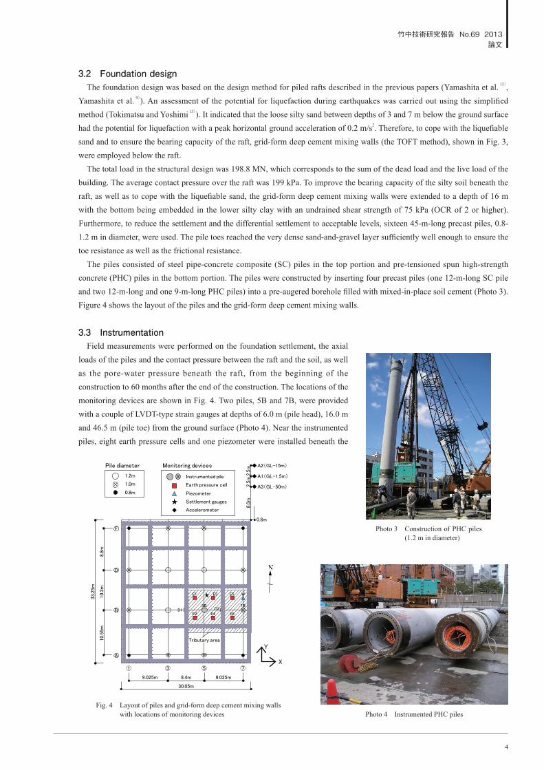
The piles consisted of steel pipe-concrete composite (SC) piles in the top portion and pre-tensioned spun high-strength concrete (PHC) piles in the bottom portion. The piles were constructed by inserting four precast piles (one 12-m-long SC pile and two 12-m-long and one 9-m-long PHC piles) into a pre-augered borehole filled with mixed-in-place soil cement (Photo 3). Figure 4 shows the layout of the piles and the grid-form deep cement mixing walls.
3.3 InstrumentationField measurements were performed on the foundation settlement, the axial
loads of the piles and the contact pressure between the raft and the soil, as well as the pore-water pressure beneath the raft, from the beginning of the construction to 60 months after the end of the construction. The locations of the monitoring devices are shown in Fig. 4. Two piles, 5B and 7B, were provided with a couple of LVDT-type strain gauges at depths of 6.0 m (pile head), 16.0 m and 46.5 m (pile toe) from the ground surface (Photo 4). Near the instrumented piles, eight earth pressure cells and one piezometer were installed beneath the
Fig. 4 Layout of piles and grid-form deep cement mixing walls with locations of monitoring devices Photo 4 Instrumented PHC piles
Photo 3 Construction of PHC piles (1.2 m in diameter)

竹中技術研究報告 No.69 2013 論文
5
raft at a depth of 4.8 m. Six earth pressure cells, E1-E6, were installed on the intact soil, and two earth pressure cells, D1 and D2, were installed on the top surface of the deep mixing walls. The vertical ground displacements below the raft were measured by differential settlement gauges. LVDT-type transducers were installed beneath the raft at depths of 5.8 m, 16.0 m, 27.1 m and 48.0 m to measure the relative displacements to a reference point at a depth of 60 m, as shown in Fig. 3. The settlements of the foundation were measured at the points on the raft by an optical level, where a bench mark was set to the monitoring point of the vertical ground displacements. The measurement of the vertical ground displacements was begun just before the foundation construction excavation, late in November 2007. The measurement of the axial loads on the piles, the contact pressure and the pore-water pressure beneath the raft was begun just before the beginning of the reinforcement of the 1.5-m-thick foundation slab. As for the observations on the seismic response of the soil-foundation-structure system, a vertical array consisting of borehole-type triaxial servo accelerometers was installed at depths of 1.5 m, 15.0 m and 50.0 m below the ground surface to record the NS, EW and UD accelerations of the free-field ground, while triaxial servo accelerometers were installed on the first and the 12th floors as well as the raft to record those of the building, as shown in Fig. 3. The data acquisition system and the devices in the seismic monitoring are shown in Table 2 and Photo 5.
3.4 Results of measurements3.4.1 Behavior of foundation before earthquake
Figure 5 shows the measured ver t ica l ground displacements below the raft. At a depth of 5.8 m, the maximum ground heaving due to the excavation was 1 4.3 mm, and then, an immediate settlement of 7.3 mm occurred due to the casting of the 1.5-m-thick foundation slab. Figure 6 shows the measured vertical ground displacements below the raft, at a depth of 5.8 m, initialised a few hours after the casting of the slab. As the immediate settlement was mostly caused by the self-weight of the unset concrete of the raft being directly transferred to the soil , the ground displacement initialised just after the immediate settlement is approximately equal to the settlement of the ‘piled raft’. The settlement of the piled raft reached 14.3 mm at the end of the construction (E.O.C.), and thereafter, slightly increased to 17.3 mm, March 10, 2011, just before the 2011 off the Pacific coast of Tohoku Earthquake. Figure 7 shows the settlement profiles of the raft measured by an optical level 22 months after the end of the construction. The maximum angular rotation of the raft was 1/1580 rad.
Photo 5 Data acquisition system
Table 2 Devices in seismic monitoring
Devices PropertiesIC Card Data Logger AD converter 24bit, Sampling 100HzServo Accelerometer(Structure & Ground) Tri-axis, Full scale: ±2000gal
Dynamic Amplifier LVDT. Frequency Response: 20HzStrain gauge LVDTEarth pressure cell: on improved soil on intact soil
LVDT, Capacity: 500kPa Capacity: 200kPa
Piezometer LVDT, Capacity: 100kPaSettlement gauge LVDT
Fig. 5 Measured vertical ground displacements
Fig. 6 Foundation settlements

竹中技術研究報告 No.69 2013 論文
6
Figure 8 shows the development of the measured axial loads of piles 5B and 7B. The pile-head loads increased after the end of the construction and reached 14.74 MN and 8.2 9 MN for piles 5B and 7B, respectively, on March 1 0, 2011. Figure 9 shows the distribution of measured axial loads for pile 7B. Since the piles were surrounded by the deep mixing walls to a depth of 16 m, the average skin friction between the depths of 6.0 m and 16.0 m was quite small, i.e., 8.9 kPa at the end of the construction and 21.8 kPa on March 10, 2011. The average skin friction between the depths of 16.0 m and 46.5 m was 54.2 kPa at the end of the construction and 68.9 kPa on March 10, 2011. The load transferred to the pile toe was relatively small, i.e. the ratio of the pile-toe load to the pile-head load was 0.18 at the end of the construction and 0.12 on March 10. Unfortunately, no data were obtained at the pile toe of pile 5B, due to the disconnection during the construction of the pile.
Figure 10 shows the development of the measured contact pressure between the raft and the soil together with the pore-water pressure beneath the raft. On March 10, 2011, the measured contact pressure between the raft and the deep mixing walls reached 296-316 kPa, whereas the pressure between the raft and the soil was 38.8-63.4 kPa. The pore-water pressure was around 30 kPa.
Figure 11 shows the time-dependent load sharing among the piles, the deep mixing walls, the soil and the buoyancy in the tributary area of columns 5B and 7B shown in Fig. 4. The sum of the measured pile-head loads and the raft load in the tributary area after the end of the construction was 35.42-39.83 MN. The raft load means the sum of the total load carried by the deep mixing walls and that by the soil, which was obtained from the measured contact pressures. The sum of the measured pile-head loads and the raft load in the tributary area was found to be consistent with the sum of the design load for columns 5B and 7B (36 MN). Figure 12 shows the ratio of the load carried by the piles to the effective load and that to the total load in the tributary area versus time, where the effective load is the total load minus the buoyancy from the water pressure acting on the base of the
Fig. 7 Measured settlement profile (22 months after E.O.C.)
Fig. 8 Measured axial loads of piles 5B and 7B
Fig. 9 Measured axial load distribution on pile 7B

竹中技術研究報告 No.69 2013 論文
7
raft. Table 3 shows the load sharing among the piles, the deep mixing walls and the soil after the end of the construction. The ratio of the load carried by the piles to the effective load increased slightly after the end of the construction and reached 0.669 on March 10, 2011. At that time, the ratio of the effective load carried by the deep mixing walls to the effective load was estimated to be 0.264, whereas the ratio of the effective load carried by the soil was 0.067. The ratio of the load carried by the piles to the total load was 0.589 on March 10, 2011.
3.4.2 Seismic observations during the 2011 off the Pacific coast of Tohoku Earthquake The 2011 off the Pacific coast of Earthquake, with an estimated magnitude of Mw=9.0 on the Moment Magnitude Scale,
struck East Japan at around 14:46 (local time) on March 11, 2011. According to the JMA, an earthquake epicenter was located about 130 km east-southeast off the Oshika Peninsura at a depth of 23.7 km. The distance from the epicenter to the building site was about 380 km.
The seismic response of the soil-foundation-structure system was successfully recorded at the site of the building (Yamashita et al. 14)). Figure 13 shows the time histories of the EW accelerations of the ground and the structure. A peak horizontal ground acceleration of 1.748 m/s2 was observed near the ground surface.
Figure 14 shows the Fourier spectra of the EW accelerations of the ground motion and those of the structure response, which
Table 3 Load sharing among piles, soil and deep mixing walls
Sep. 16, 2008*1 Mar. 10, 2011*2 Mar. 11, 2011*3 Mar. 15, 2011 Sep. 3, 2013Ratio of load carried by piles, αp’ 0.646 (0.540) 0.669 (0.589) 0.660 (0.580) 0.667 (0.582) 0.663 (0.576)Ratio of effective load carried by deep mixing walls, αg’ 0.283 0.264 0.266 0.266 0.278Ratio of effective load carried by soil, αs’ 0.071 0.067 0.074 0.067 0.059Values in parentheses are ratios of pile load to total load *1 End of construction *2 Pre-earthquake *3 600s after start of event
Fig. 10 Measured contact pressure and pore-water pressure
Fig. 11 Time-dependent load sharing among piles, deep mixing walls and soil in tributary area
Fig. 12 Ratios of load carried by piles to effective load and total load in tributary area
0.0
0.2
0.4
0.6
0.8
1.0
0 200 400 600 800 1000 1200 1400 1600 1800 2000 2200
Rat
io o
f lo
ad
car
ried b
y p
iles
Time (days)
E.O.C.Sep. 16, 2008
▽
Tohoku EarthquakeMar. 11, 2011
▽Sep. 3, 2013
▽
Effective load
Total load

竹中技術研究報告 No.69 2013 論文
8
Fig. 13 Time histories of EW accelerations of ground and structure
Fig. 14 Fourier spectra of EW accelerations
Fig. 15 Excess pore-water pressure beneath raft

竹中技術研究報告 No.69 2013 論文
9
were smoothed by 0.05Hz Parzen window. As to the accelerations near the ground surface, it can be seen that components of the periods of 0.7, 1.0 and 1.2 s were predominant. The responses of the first floor and the 12th floor, were amplified around 3.5 s, which is consistent with the natural period of the base-isolation system.
Figure 15 shows the pore-water pressure induced by the earthquake in the silty sand beneath the raft. The pore-water pressure increased monotonically to 0.47 kPa 600 s after the start of the event. There was very little excess pore-water pressure and no liquefaction occurred in the silty sand beneath the raft. In addition, no evidence of liquefaction was observed at the site of the building.
Figure 16 shows the horizontal displacements near the ground surface relative to those at the depth of 50 m vs. the bending moments at the pile head. It was found that the bending moments in EW direction were considerably larger than those in NS direction for both piles. The bending moments at the pile head tend to increase with the increase in the relative horizontal dis-placements for both piles 5B and 7B. Since the accelerations of the superstructure, which corresponded to inertia force of the superstructure, were relatively small due to the base-isolation system as can be seen in Fig. 13, it is presumed that the bending moments at the pile head were mainly caused by the horizontal ground displacements rather than the shear force resulted from the inertia of the superstructure.
Figure 17 shows the time histories of the axial loads of the piles. It can be seen that the axial loads for piles at all depths were in compression during the earthquake. The maximum amplitude for pile 5B at the pile head was 860 kN in compression and 853 kN in tension, while that for pile 7B at the pile head was 694 kN in compression and 1030 kN in tension. The largest amplitudes of axial load occurred at intermediate depths for both piles. Furthermore, the ratio of the load amplitude at the pile toe to that at the pile head was 1.07 in compression and 0.48 in tension, which is considerably larger than the ratio of the pile-toe load to the pile-head load in the static measurements. The increments in axial loads were relatively small because the superstructure was moving primarily in a sway mode by the base-isolation system. The ratio of the maximum amplitude to the axial load at the pile head on March 10, 2011 was 5.8% for pile 5B in the inner part of the raft and 12.4% for pile 7B near the periphery.
Fig. 16 Relative ground displacements vs. bending moments at pile head

竹中技術研究報告 No.69 2013 論文
10
Figure 18 shows the interaction curves of the axial load and the bending moment of the SC pile corresponding to the allowable and the ultimate bending moments for an axial force in design. Figure 18 also shows the relationship between the axial loads and the bending moments measured for piles 5B and 7B at the pile head during the earthquake, where the bending moments are obtained by combining the components in NS and EW directions. Here, the allowable interaction curve is defined when the unit stress at the edge of the steel pipe reaches the yield stress of 325 N/mm2 in tension and/or that of the concrete reaches 60 N/mm2 in compression. The ultimate interaction curve is defined when the unit stress at the edge of the concrete reaches the compressive strength of 105 N/mm2 and the compressive strain at the edge reaches 5000 micro strain. It is found that the observed bending moments for both piles are considerably smaller than the allowable bending moment of the pile. This is likely that the relative horizontal displacements of the piles to soil below the raft to the depth of 16 m, where the soil was confined by the deep mixing walls, were small.
3.4.3 Effect of earthquake on settlement and load sharingThe foundation settlement increased by 0.3 mm from the
pre-earthquake value, the value measured on March 10, 2011, to 17.6 mm on March 15, 2011, as shown in Fig. 6. Thereafter, the foundation settlements varied from 16.2 to 17.8 mm and were found to be stable. The axial load at the pile head of pile 7B decreased very slightly from the pre-earthquake value of 8.29 MN to 8.15 MN on March 15, while that on pile 5B changed little, as shown in Fig. 8. Thereafter, the axial load varied from 14.19 to 15.31 MN on pile 5B and from 8.02 to 8.34 MN on pile 7B. The contact pressure between the raft and the soil increased from the pre-earthquake values (39.3-63.3 kPa) to 40.6-65.6 kPa on March 15, as shown in Fig. 10. Thereafter, the pressure varied from 38.8 to 64.9 kPa. The contact pressure between the raft and the deep mixing walls near the periphery (D2) increased slightly from the pre-earthquake value of 316 to 321 kPa and that in the inner part (D1) increased very slightly from 296 to 298 kPa on March 15, as shown in Fig. 10. Thereafter, the contact pressure near the periphery (D2) increased slightly, whereas that in the inner part (D1) changed little. The pore-water pressure
Fig. 18 Interaction curves for axial load and bending moment of SC pile
Fig. 17 Time histories of axial loads of piles

竹中技術研究報告 No.69 2013 論文
11
increased from the pre-earthquake value of 30.1 kPa to 32.4 kPa on March 15. Thereafter, the pore-water pressure varied from 30.2 to 35.6 kPa due to the effect of seasonal groundwater variations. It is likely that the variations in foundation settlement and axial load of the piles, before and after the earthquake, are closely related with the seasonal groundwater variations.
The ratio of the load carried by the piles to the effective load in the tributary area decreased slightly from the pre-earthquake value of 0.669 to 0.660 near the end of the event (600 s after the start of the event), and then increased to 0.667 on March 15, as shown in Table 3. The ratio of the effective load carried by the soil to the effective load increased from the pre-earthquake value of 0.067 to 0.074 near the end of the event, and then decreased to 0.067 on March 15, whereas that carried by the deep mixing walls to the effective load increased very slightly from 0.264 to 0.266, and then increased a little to 0.278 on September 3, 2013, as shown in Table 3. This indicated that presumably a very small amount of load transfer from the soil to the piles occurred after the load transfer from the piles to both the soil and the deep mixing walls during the earthquake. Thereafter, the ratio of the load carried by the piles to the effective load was quite stable, as shown in Fig. 12 and Table 3.
As a result, no significant changes in foundation settlement or load sharing were observed after the earthquake, where very little excess pore water pressure had built up beneath the raft.
4 TWELVE-STORY OFFICE BUILDING
4.1 Building and soil conditionsThe 12-story office building, shown in Photo 6, is
located in Tokyo, 0.3 km southeast from the twelve-story residential building (Yamashita et al. 15)). Figure 19 shows a schematic view of the building and the foundation with a soil profile. The building, 55.7 m in height above the ground surface and measuring 120 m by 100 m in plan, is a steel-framed structure with a base isolation system of laminated rubber bearings. The plan area of this building is about twelve times larger than that of the 12-story residential building. The foundation levels were between depths of 3.6 and 7.2 m.
Fig. 19 Schematic view of building and foundation with soil profile
Photo 6 12-story office building in Tokyo

竹中技術研究報告 No.69 2013 論文
12
The subsoil consists of an alluvial stratum to a depth of 44 m below the ground surface, underlain by a diluvial very dense sand. The ground water table appears approximately 3 m below the ground surface. The soil profile down to a depth of 15 m is made of fill which consists of loose clayey sand, sandy clay and rubble. Between the depths of 15 to 44 m, there lie very soft to medium silty clay which is slightly overconsolidated with an OCR of 1.3 or higher. The shear wave velocities derived from a P-S logging were 150 m/s at the foundation levels and 290 m/s in the dense sand below the depth of 44 m.
4.2 Foundation designAn assessment of a potential of liquefaction during earthquakes
indicated that the loose clayey sand between the depths of 5 to 15 m had a potential of liquefaction during earthquakes with the peak horizontal ground acceleration of 3.0 m/s2. The foundation level was between depths of 3.6 and 7.2 m, therefore, grid-form deep cement mixing walls were introduced to cope with the liquefiable clayey sand below the raft.
Foundation design was on the basis of the experience with the 12-story residential building. The average contact pressure over the raft is 187 kPa. To improve bearing capacity of the raft, the grid-form deep cement mixing walls were extended to the depth of 20 m with the bottom being embedded in the silty clay with undrained shear strength of 100 kPa or higher. Furthermore, to reduce the settlement and the differential settlement to an acceptable level, 180 pre-tensioned spun high-strength concrete (PHC) piles of 0.6 to 1.2 m in diameter were used. The pile toes were embedded in the very dense sand below the depth of 44 m enough to ensure the toe resistance as well as the frictional resistance. The pile was constructed by inserting the precast piles into a pre-augered borehole filled with mixed-in-
Fig. 20 Layout of piles and grid-form deep cement mixing walls Fig. 21 Locations of monitoring devices
Photo 7 LVDT-type strain gauge
Photo 8 Instrumented PHC pile

竹中技術研究報告 No.69 2013 論文
13
place soil cement. Figure 20 shows a layout of the piles and the grid-form deep cement mixing walls.
4.3 InstrumentationField measurements were performed on the foundation settlement, the axial loads of the piles and the contact pressure
between the raft and the soil, as well as the pore-water pressure beneath the raft, from the beginning of the construction to 21 months after the end of the construction. The locations of the monitoring devices are shown in Figs. 20 and 21. Four piles, P1, P2, P3 and P4, were provided with a couple of LVDT-type strain gauges at depths of 8.5 m (near pile head), 20.0 m and 47.0 m (near pile toe) from the ground surface (Photos 7 and 8). In the tributary area of the instrumented piles, six earth pressure cells and one piezometer were installed beneath the raft at the depth of 7.2 m. Earth pressure cells E1-E3 were installed on the soil and earth pressure cells D1-D3 were installed on the deep mixing walls. The vertical ground displacements below the raft were measured by differential settlement gauges. LVDT-type transducers were installed beneath the raft at depths of 8.5 m, 14.0 m, 20.0 m, 35.0 m and 50.0 m to measure the relative displacements to a reference point at a depth of 60.0 m. The settlements of the foundation were measured at the monitoring points on the raft by an optical level. The measurement of the vertical ground displacements was begun during the foundation construction excavation. The measurement of the axial loads of the piles, the contact pressures and the pore-water pressure beneath the raft was begun just before the casting of the 0.6-m-thick foundation slab.
4.4 Results of measurements4.4.1 Behavior of foundation
Figure 22 shows the measured vertical ground displacements below the raft. The measured ground displacement at the depth of 8.5 m after the casting of the foundation slab was approximately equal to the foundation settlement. The foundation settlement increased considerably just before the end of the construction (E.O.C.) due to the water pouring into the underground pits. There-after, the foundation settlement became stable and reached 21 mm at the end of the observation (August 8, 2013). Figure 23 shows the settlement profile of the raft measured by the optical level about 1.5 months before the end of the construction. The measured settlements were 12 to 24 mm and the maximum angular rotation of the raft was 1/1400 rad. which satisfied the design requirements.
Figure 24 shows the development of the measured axial loads of piles P1-P4. The axial loads also increased considerably just before the end of the construction due to the water pouring. Thereafter, the pile-head loads were stable and reached 4.7-11.3 MN at the end of the observation. Figure 25 shows the distribution of the measured axial loads on pile P1. Since the piles were surrounded by the deep mixing walls to a depth of 20.0 m, the skin friction of the pile shaft between the depths of 8.5 and 20.0 m was quite small. The average skin friction between the depths of 20.0 and 47.0 m was 85 kPa and the ratio of the pile-toe load to the pile-head load was 0.20 at the end of the observation. Figure 26 shows the development of the measured contact pressure between the raft and the soil and the pore-water pressure beneath the raft. The measured contact pressure between the raft and the soil seemed to reach a state of equilibrium in early stage of the construction, while the pressure between the raft and the deep mixing walls increased with construction loading in the same way as the axial loads of the piles. The measured contact pressure between the raft and the deep mixing walls and the contact pressure between the raft and the soil were stable after the end of the construction. At the end of the observation, the contact pressure between the raft and the deep mixing walls reached 131-182 kPa and the contact
Fig. 22 Measured vertical ground displacements below raft
Fig. 23 Measured settlement profile of raft (Oct. 12, 2011)

竹中技術研究報告 No.69 2013 論文
14
pressure between the raft and the soil reached 64-71 kPa. The measured pore-water pressure was quite stable (38-40 kPa) before and after the end of the construction.
Figure 27 shows the time-dependent load sharing among the piles, the soil, the deep mixing walls and the buoyancy in the tributary area of the instrumented piles shown in Fig. 4. The sum of the measured pile-head loads and the raft load in the tributary area varied from 61.3 to 63.0 MN after the end of construction, which was generally consistent with the design load of 64.0 MN. Figure 28 shows the ratios of the load carried by the piles to the effective load and that to the total load in the tributary area versus time. The ratio of the load carried by the piles to the effective load was estimated to be 0.70 just before the end of the construction and increased only slightly to 0.71 at the end of the observation. Meanwhile, the ratio of the effective load carried by the deep mixing walls to the effective load was 0.14 and the ratio of that carried by the intact soil to the effective load was 0.15 at the end of the observation.
4.4.2 Effect of earthquake on settlement and load sharing
On March 11, 2011, 9 months before the end of the construction, the 2011 off the Pacific coast of Tohoku Earthquake struck the site of the building. The contact pressure between the raft and the deep mixing walls increased markedly after the earthquake as shown in Fig. 26(a), while the contact pressure between the raft and the soil changed a little as shown in Fig. 26(b). As a result, no significant changes in foundation settlement or load sharing were observed after the earthquake, as shown in Figs. 22 and 28.
Fig. 26 Measured contact pressures and pore-water pressure beneath raft
Fig. 25 Axial load distribution on pile P1
Fig. 24 Measured axial loads of piles

竹中技術研究報告 No.69 2013 論文
15
5 CONCLUSIONS
A piled raft combined with the grid-form deep cement mixing walls was employed for two 12-story base-isolated buildings, the residential and the office buildings, to cope with the liquefiable loose sand as well as to reduce the consolidation settlements of the soft cohesive soil below the loose sand. The buildings are located closely and the plan area of the office building is about twelve times larger than that of the residential building. To confirm the validity of the foundation design, long-term field measurements were performed on the foundation settlements and the load sharing between the raft and the piles from the beginning of the construction to 60 and 21 months after the end of the construction for the residential and the office buildings. Based on the field measurement results, the following conclusions can be drawn: ・ The measured vertical ground displacements just below the raft, which were approximately equal to the foundation
settlements, were 17 and 21 mm for the residential and the office buildings. And the ratios of the load carried by the piles to the effective load in the tributary area were estimated to be 0.66 and 0.71 for the former and the latter buildings at the end of the observation. The foundation settlements and the ratios of the load carried by the piles to the effective load were found to be quite stable after the end of the construction.
・ During the monitoring period, the 2011 off the Pacific coast of Tohoku Earthquake struck the sites of the buildings. Based on the measurement results before and after the earthquake, no significant changes in foundation settlement or load sharing were observed after the earthquake.
Consequently, it is confirmed that a piled raft combined with grid-form deep cement mixing walls works effectively in grounds consisting of liquefiable sand and soft cohesive soil.
ACKNOWLEDGEMENTSThe authors are grateful to Messrs. H. Abe, Y. Yamaguchi, H. Matsuzaki and H. Nagaoka of Building Design Department
(Tokyo Main Office) of Takenaka Corporation for their contribution to the foundation design.
REFERENCES 1) Burland, J. B., Broms, B. B. and de Mello, V. F. B.: Behaviour of foundations and structure, Proc. of the 9th ICSMFE, Vol. 2,
495-546, 1977. 2) Randolph, M. F.: Design methods for pile groups and piled rafts, Proc. of the 13th ICSMFE, Vol.5, 61-82, 1994. 3) Poulos, H.G.: Piled raft foundations: design and applications, Geotechnique 51, No. 2, 95-113, 2001. 4) Katzenbach, R., Arslan, U. and Moormann, C.: Piled raft foundation projects in Germany, Design applications of raft
foundations, Hemsley J. A. Editor, Thomas Telford, 323-392, 2000. 5) Yamashita, K. and Kakurai, M.: Settlement behavior of the raft foundation with friction piles, Proc. of the 4th Int. Conf.
on piling and Deep Foundations, 461-466, 1991. 6) Yamashita, K.: Field measurements on piled raft foundations in Japan, Proc. of the 9th Int. Conf. on Testing and Design
Methods for Deep Foundations: IS-Kanazawa 2012, 79-94, 2012.
Fig. 27 Time-dependent load sharing between raft and piles in tributary area
Fig. 28 Ratios of pile load to effective load and total load in tributary area
竹中技術研究報告 No.69 2013 論文
16
7) Mandolini, A., Russo, G. and Viggiani, C.: Pile foundations: Experimental investigations, analysis and design, Proc. of the 16th ICSMGE, Vol.1, 177-213, 2005.
8) Yamashita, K.: A study on settlement and load sharing of vertically loaded piled raft foundations, Dr. Thesis of Tokyo Institute of Technology, 2010.
9) Yamashita, K., Yamada, T. and Hamada, J.: Investigation of settlement and load sharing on piled rafts by monitoring full-scale structures, Soils & Foundations, Vol.51, No.3, 513-532, 2011.
10) Yamashita, K., Hamada, J. and Yamada, T.: Field measurements on piled rafts with grid-form deep mixing walls on soft ground, Geotechnical Engineering Journal of the SEAGS & AGSSEA, Vol.42, No.2, 1-10, 2011.
11) Tokimatsu, K., Mizuno, H. and Kakurai, M.: Building damage associated with geotechnical problems, Soils & Foundations, Special Issue on Geotechnical Aspects of the January 17 1995 Hyogoken-Nambu Earthquake, 219-234, 1996.
12) Yamashita, K., Yamada, T. and Kakurai, M.: Simplified method for analyzing piled raft foundations, Proc. of the 3rd Int. Geotechnical Seminar on Deep Foundations on Bored and Auger Piles BAP Ⅲ, Vol.51, 457-464, 1998.
13) Tokimatsu, K. and Yoshimi, Y.: Empirical correlation of soil liquefaction based on SPT N-value and fines content, Soils & Foundations 23 (4), 56-74, 1983.
14) Yamashita, K., Hamada, J., Onimaru, S. and Higashino, M.: Seismic behavior of piled raft with ground improvement supporting a base-isolated building on soft ground in Tokyo, Soils & Foundations, Special Issue on Geotechnical Aspects of the 2011 off the Pacific coast of Tohoku Earthquake, Vol.52, No.5, 1000-1015, 2012.
15) Yamashita, K., Wakai, S. and Hamada, J.: Large-scale piled raft with grid-form deep mixing walls on soft ground, Proc. of the 18th ICSMGE, 2637-2640, 2013.