machine modification design - ammattikorkeakoulut
TRANSCRIPT

MACHINE MODIFICATION DESIGN
Thesis
Adeniyi Folorunso
Degree Programme in Industrial Management Engineering and International Business
Accepted __.__.___ _________________________________

SAVONIA UNIVERSITY OF APPLIED SCIENCES, BUSINESS AND ENGINEERING, VARKAUS Degree Programme
Industrial Engineering and Management Author
Adeniyi Folorunso Title of Project
Machine Modification Design
Type of Project Date Pages
Final Project 03.06.2010 35 Academic Supervisor Company Supervisor Company
Seppo Ryynänen Pekka Törrönen Itä-Suomen Balanssi Oy Abstract The project was done in a medium-sized company known as Itä-Suomen Balanssi located in the city of Varkaus. The goal of the project was to upgrade the old mechanical equipment to fit the current demand and this was done by acquiring enough information about the equipment, the use of the equipment, by determining shortcomings of the equipment and solutions, for determining the shape of the individual part to be used, having the detailed dimensions of each part and then using the inventor program to prepare the drawing. As a result of this project, it can be said that modifying the old equipment reduces costs to the minimum in the sense that sixty-five percent of the new equipment price is cut-off, saves time and the familiarity of the equipment is constant. In this project, it is seen that equipment modification made life simple when thinking about future development because machine redundancy will be reduced.
Keywords
Heavy duty equipment, Light equipment, Computer aided design, Modeling, 3D Scanners, Tolerance. Confidentiality
Confidential

I
TABLE OF CONTENTS
ABSTRACT
1. INTRODUCTION 1
1.1 Background of the study 1
1.2 Itä-Suomen Balanssi Oy 1
1.2.1 Area of Specializations 2
1.2.2 Equipment/machines used by the Company 2
1.2.3 Problems facing the company in terms of equipment 3
1.2.4 Solution hints 3
2. BASIC CONCEPTS AND TERMS 5
2.1 Design for manufacture and assembly 5
2.2 Philosophy of design for manufacture and assembly 6
2.3 The implementation of design for manufacture and assembly 6
2.4 Functionality 6
2.5 Manufacturing issues 7
2.6 Handling and assembly 8
2.7 Computer aided design and manufacture (CAD/CAM) 10
2.8 3D scanners 10
3. PROCESS DESCRIPTION AND STEPS 12
3.1 Preliminaries 12
3.2 Project plan 12
3.3 Assessment and comparison between the old equipment
and the new tractor 13
3.4 Problems encountered and their identification 14
3.5 Source of the problem 15
3.6 Gathering information needed for the study 16

II
4. DESIGN STAGE 18
4.1 Equipment modification design 18
4.2 Components and assemblies 18
5. CONCLUSIONS 26
REFERENCES 27
APPENDIX 28

1
1. INTRODUCTION 1.1 Background of the study
There is an increase in technological methods in all daily activities. This is done to
improve the efficiency, quality and cost reduction of a particular product. Many
manufacturers try to be up-to-date in their products’ improvement without thinking
the effects on their customers. Although it is good for customers to have the latest
version of particular products but if the interest of their valued current customers is
to be put into consideration there should be a stand-by solution to their previous
products improvement to suit the latest version to some extent if not one hundred
percent.
This has been one of the major problems of companies nowadays because their
equipment and machines are very expensive and the manufacturers should not
expect the customers to buy the new products anytime they are released. This was
the reason to examine equipment modification. This was carried out in a medium-
sized company Itä-Suomen Balanssi Oy. 1.2 Itä-Suomen Balanssi Oy Itä-Suomen Balanssi Oy (ISB) is a company located in Varkaus in Eastern Finland.
Their major business area is building, renovation, cleaning, care and maintenance.
It is a Finnish company established in 2006 and their staff has decades of
experience and solid skill. ISB offers a good quality and knowledgeable service and
they are time-minded.
ISB also deal with home or business premises cleaning, renovation of the building
or additional need in the masonry walls, stairs and wet areas for painting
renovation, cleaning of the offices and homes’ yard service areas and making of
garden and household chores.

2
The staff of ISB includes experienced carpenters, metal and construction work. The
foremen, regarded as seniors, guide the work and are involved in any activity that is
going within the younger ones. [5]
1.2.1 Area of Specializations The company has different areas of specialization which include the following. ISB Renovation: It deals with home and business premises renovation and value
restoration and all other things that have something to do with maintenance such
as: toilet and bathroom renovations and tiling, unimpeded flow of the solutions,
walls/floor corrections, furniture installation, furniture customization, repairs to
structures, roofing and roof installation, sweeping, hats chimney and sheet metal
construction products. [5]
Gardening and Landscaping: This is making your home and the nearby
courtyard’s environment comfortable to suit your taste and this includes plantations,
places to barbecue, garden furniture and flagpoles, tiling, landscape management
and clearing activities, external site management, storm water systems
maintenance and cleaning, tree and shrub cuttings, sowing of grass and grass-
cutting, composting, other yard work and landscaping. [5]
Building work: This deals with construction like garages, warehouses, outdoor
saunas, patios and terraces, wind cabinets, flagpoles and sliding. [5]
1.2.2 Equipment/machines used by the company Equipment used in the company is of two types: Light and Heavy duty equipment
Light equipment includes a drilling machine, a circular saw machine, a cutting
machine, welding machines, mowers, grinders and sweepers.

3
Heavy duty equipment includes a tractor, vans and buses, a backhoe, pale-loader,
a trailers and tippers. [5]
1.2.3 Problems facing the company in terms of equipment Due to technological advancement, some of the old tractors’ attachments (e.g.
backhoe for digging trenches) are not suitable for the newly bought tractor this
causes a big problem for the company because it means that they have to buy new
attachments again for the newly bought tractor. The suitability has nothing to do
with strength and efficiency but coupling, fixing and assembling them together is the
major problem. 1.2.4 Suggested solutions As it is known in any company that to be a good manager you have to be money
conscious and minimize your cost to the lowest with a very high efficiency. This is
explained better by using the graph in figure 1.
Efficiency %
Cost/Timet
Solution format line
Target area
Figure 1. Solution format line graph.

4
As it is seen in the above diagram, there are two things to put into consideration
when you are thinking about a solution to this problem.
1. Cost
2. Efficiency
The cost of the suitable solution must be low with very high efficiency as it is shown
in the graph as target area.
There are various types of suggested solutions and their short comings which are:
1. Buying a new attachment for the new tractor (High cost)
2. Managing the old one with help of some supports (Low efficiency and cost)
3. Buying a suitable old tractor for the attachment or new attachment for the
newly bought tractor(High cost)
4. Redesigning of the coupling area/parts for easy fittings (High efficiency, low
cost and less time)
By carefully checking the figure 1 graph, it will be seen that the target area can be
found in the fourth option which makes it the most suitable option to choose.

5
2. BASIC CONCEPTS AND TERMS
2.1 Design for manufacture and assembly
In order to have a good design, the designer needs to start with what is called a
design brief which can be gathered within the company itself and from the existing
or potential customers who wish to satisfy market demand by developing a new
product. A design brief is just what your clients really need from you.
It includes:
Client’s requirements
Functional requirements
Maximum permissible project and product costs based upon the perceived
market
Market details
Quality requirements
After the design brief has been evaluated, the key design features will be known
and concerned with:
Aesthetic requirements
Contextual requirements
Performance requirements
Production parameters and constraints such as availability of labour,
materials, technology and health and safety requirements.
Alternatively, while proposing design feasibility studies are also needed to be
carried out in order to give a realistic presentation to the client. The final design will
be planned in accordance to associated quality specifications requirements given
by national and international standards organizations, safety and environmental
legislation and legally binding notes of guidance for the category of product
concerned. Although it may be a bit costly at the end but those requirements have
to be met. [1]

6
2.2 Philosophy of design for manufacture and assembly
As it is known that design is the first thing to have in mind when thinking about
manufacturing a new product and can have a great effect on cost of the product so
the philosophy of design for manufacture and assembly looks into cost reduction by
manufacturability improvement with ease of assembly of a particular product. [1]
2.3 The implementation of design for manufacture and assembly
Naturally, the manufacturing engineers usually have one problem or the other in
doing their job because they do not participate in the designing stage which made
the designers’ work to be termed as over-the-wall approach. To overcome this, a
team has to be built called Concurrent Engineering Teams and they will give some
criteria for manufacturability and assembly for proposed design. [1]
The criteria are:
Functionality
Manufacturing issues
Handling and Assembly
2.4 Functionality
A component consists of different parts. The functional part is the one that really
has critical assignment that leads to the performance of the component. The non-
functional part does not have major work in component existence but it has to do
with maintenance, covers, inspection and aesthetical value and it must be reduced
to the minimum to have low production cost. [1]

7
2.5 Manufacturing issues
Manufacturing issues is a topic that has to do with the manufacturing process and
materials. The complexity of the manufacturing process, type and quality of the
materials to be used has a great effect on production cost of the product. In
addition, amount to be produced affects materials’ volume cost but design process
and method does not go along with the number of products to get, cost spent on
design is fixed. To reduce cost on manufacturing issues, some certain points have
to be clarified which are [1, 2]:
Complexity: Component’s shape has a great effect on the manufacturing
method. Different types of shape have a distinct suitable method of making
them and how the structure looks like also gives the best idea of the method
to be used e.g. simple cylindrical shape can be manufactured by turning but
if it has a thin wall, a bit complex other method has to be looked into because
of strength and accuracy.
Material suitability: Material suitability is one of those things to be kept in
mind when deciding on the type of materials to be used for a particular
product because some materials are really good for some processes while
some are bad due to their physical and chemical properties e.g. copper, zinc,
lead and some aluminium alloys are easier to work with by impact extrusion
process than steel and steel alloys are easier to hot forge than aluminium
alloys.
Wall thickness: A certain wall thickness of a particular product has a
suitable manufacturing process e.g. sand casting (greater than 3mm thick),
die-casting (0.6mm≥3mm) and sheet metal pressings and impact extrusion
(>0.6mm).
Tolerance and surface finish: The equipment with high tolerance will be
costly because of increase in processing time and tools handling regulations
which make it easier to be handled with care.

8
Process cost: A component to be manufactured has to pass different
processes and stages and each process can’t be completed without the
financial aspect. Money spent on each process is known as process cost
and the addition of different process costs make the production cost.
Waste: Some processes are regarded as waste because of the materials
disposed of as scrap while manufacturing them and some consume really
long time to complete the process. It is the task of production economics to
assess both situations and balance it and come up with the best choice to be
used.
Treatment: Surface treatment cost varies depending on the type of materials
used. Some materials are costly but they do not need any other surface
treatment while some are not expensive but they require additional surface
treatment for quality improvement. The product designer in consultation with
customer can decide how the balance will be made.
2.6 Handling and assembly
When thinking about handling and assembly of a component it should also be
considered how redesigning of a product can lead to reduction in parts quantity as it
is known that for smaller parts less time is to be spent on handling and assembly of
the product. [1]
Handling: Poor design of a component will result to difficulties in manual or
mechanical handling of the product. An example of this is a fragile and
delicate product or a product with unnecessary weight which makes it too
heavy to be suitable for what it is meant for or to serve its purpose.
Assembly: It is also good to check how a component can be coupled to
another to test and assess its functions. Difficulties in handling and
obstructions are also signs of poor design.

9
The features of good design include the following:
Orientating one about how the product can be positioned correctly at
the first attempt.
There should be no resistance to insertion.
Assessing the product must not be restricted by any means
There should be no additional joining process such as bolting,
soldering or adhesive bonding.
To achieve all these criteria, all the components:
Should be symmetrical, if possible and this also helps in manufacturing
Have polar geometry mark.
Have important directions.
Should be tangle proof.
Should have consistency in the dimensions used for feeding,
orientation and location
Should be self-locating.
Should have a datum surface
If volume of production and cost are to be kept in mind, it is important that
assembly:
Should have location points
Will be designed to start from top
Should be designed to avoid unnecessary turning over of the product
Should be designed to allow series of subassemblies for intermediate checks
Should incorporate standardized parts e.g. fasteners in order to facilitate
assembly and correct selection.

10
Should reduce complications and eliminate components that are not
important. [1,2]
2.7 Computer aided design and manufacture (CAD/CAM)
This chapter deals with the use of computer hardware and graphics software to
make design drawings. Nowadays CAD tools make the designer to produce a
realistic image of a product to be manufactured with accuracy. It is a system that
automatically produces finished products by using computer controlled production
machines.
Both CAD and CAM work together. A digital model will be generated in CAD which
will be used as input in CAM software package after the physical shape of the
product has been known before composing a proper set of fabrication instructions
to a production machine.
The CAD/CAM operators are very useful in every area of design with an
architectural design background and creative talent because every design starts
from a rough sketch and own thinking. A CAD/CAM operator must be able to read
and write with a college level of algebra, trigonometry, and manual drafting
practices, the window operating system, 2D and 3D manual sketches. [1]
2.8 3D Scanners
3D scanners capture physical measurements of a real object by scanning it and
transfer the data into a viewable 3D format on the computer. As it is known, CAD is
based on ideal mathematics by giving the features of the model from the
imagination to reality but a 3D scanner works on a physical real-world object to form
its imagination, that is, in the opposite direction. The reverse engineering Process
starts from scanning the object, re-bridging the data and sending to CAD model for
manufacturing. It is fastest way to put an object onto the computer with physically
accurate three dimensional measurements. The 3D scanner is represented with a
scale digital model or a 3D graphical rendering. When the object is scanned, all its
features like length, width, height, volume, surface area, location and size will be
processed as given data to produce the drawing of the object in a 3D mode.

11
The coordinates are measured in data capture application but to get the information
correctly, you have to avoid some errors which include: improper datum schemes,
probe compensation and environmental effects like temperature and rigidity of the
table. [4]
Types of 3D scanner:
3D Laser scanning
White light scanning
Photogrammetry
Machine vision
Coordinate measuring machines
Destructive slicing
3D CT or MRI scanning
Theodolite
Trackers
Advantages:
Physical object measurements can be done quickly
It shortens the design work time
It makes components’ assembling easier
The inheritance of manufactured parts made easy
It limits the difference between as-designed and as-built

12
3. PROCESS DESCRIPTION AND STEP 3.1 Preliminaries The needed tools were gathered and machines and other equipment to be used
were checked well. Due to the nature of the study which caused some
measurements to be done manually some other tools were also constructed for
determination of perpendicularity of an object.
3.2 Project plan The project plan was done without including the time schedules and it goes thus:
Assessing and studying the old equipment
New tractor assessment
Comparing and contrasting the two
Identifying the problems
Knowing the source of the problem
Checking out for people’s opinion about the problem
Suggested solutions and their assessment and comparison
Choosing of the most suitable, reasonable, cost effective and with high
efficiency
Gathering information needed for the project like measuring, checking
shapes etc.
Drawing the rough sketch and its compatibility with the old equipment
Designing
Modeling
Re-designing
Testing of the re-designed parts
Finishing the process

13
3.3 Assessment and comparison between the old equipment and the new tractor Information about the workability of the former tractor attachment was gathered and
some critical points like joints, coupling areas, turning areas, valves, gear, both
dead and live loads etc. were noticed and some questions were asked and
answered like how does it work, means of connection, area of connection etc. In
this way, more information about how the machine was being operated before was
gathered.
The new tractor is information guide was studied to know both the physical and
structural properties of the tractor and the structural members’ properties were also
checked to know the maximum loading capability of those members e.g. chassis,
axle etc.
By comparing all the information received or gathered from both the old equipment
(tractor attachment) and the new tractor, it was discovered that both of them are
capable to work together but there will be more efforts to be put in the coupling area
to aid the assembling system so that the tractor can take it conveniently and
everything will be balanced both structurally and physically. Figures 2 and 3. show
the parts that are to be coupled together.
Figure 2. Picture showing the coupling area of the old equipment.

14
Figure 3. Picture showing the coupling area of the tractor.
3.4 Problems encountered and their identification
It was discovered that the cylinders and other structural members used in the new
tractor’s coupling chamber did not have enough strength to hold the old equipment
while working. Physically, it was seen that there should be an additional support for
the stability of the system if they are to be used together. Details can also been
seen in figure 4.

15
Figure 4. Picture showing the structural parts used for the connection.
3.5 Cause of the problem
After checking the mechanism well, it was seen that the all the forces coming from
the equipment while at use which make it to be in form of cantilever were
transferred to the main tractor through the same mechanism that is responsible for
automation, feeding of hydraulic oil and the gearbox for the hydraulic control of the
system which lead to low efficiency and parts’ to the fact that the parts wear out
easily.
Suggested solutions gathered are:
Buying the new one
Welding and repairing the damaged part
Re-designing of the joint/coupling area

16
The assessment of the suggested solutions and gathered opinions:
Buying the new suitable equipment is good in terms of efficiency and time
but too costly in terms of money to be incurred and wasting of old resources
(formal equipment).
Welding and repairing the damaged part gives low efficiency, an unreliable
system, is time consuming but saves money when thinking about short time
effect.
Re-designing the product also gives a permanent solution to the problems,
reasonable cost, and high efficiency without wasting of resources (formal
equipment).
Comparison:
As it is known that there are two things to be put into consideration and they
are cost and efficiency. After checking all the options available, it was
discovered that re-designing gives what is really wanted because there is
cost reduction with high efficiency.
3.6 Gathering information needed for the project
Steps taken in this area are:
Preliminaries
Looking out for the same type of machine and seeing how it is coupled
together to give a brief idea of what is really needed for the work. This was
accomplished by discovering the same kind of equipment in Varkaus main
cemetery located at savontie and enlightened the idea.
The manual of the new tractor was carefully studied in order to know the
features of the chassis and axle like their dimensions, shapes, spaces
available etc
Taking some real measurements of the area and parts needed for the
equipment and thinking how the placement will be done conveniently. In
order to get an accurate number, a tool was constructed which gives
perpendicular distance and enhances accuracy.

17
Rough sketch
The gathered information and ideas were put into rough sketch for criticism and
assessment where some short-comings were found and corrected. With this the
final shape was and concluded.
Designing
Different parts to be designed were listed and basic information and the shape of
each part were listed as criteria under each part before the work continued. More
information about these parts will be given in chapter four.
Modeling
The models of some critical parts like the one to be attached to axle member were
done by using wood to test if the part will fix in well or not. This later led to making
some corrections and amendments in order to get them fixed well to the new
tractor.
Redesigning and testing
After checking the compatibility of the models made, some corrections were made
which means that the part will be redesigned, models will be done and checked
again. The process continued until the suitable and accurate one was done.
Finishing the process
The surfaces of the parts agreed to be painted with a black glossy paint to prevent
rusting and matched colour of the new tractor’s chassis colour.

18
4. DESIGN STAGE
4.1 Equipment modification design
The distance required for the attachment to fit well to the tractor was really
mastered to minimize any kind of difficulties that may arise during assembling.
Due to the nature and source of the problem, the best place and structural member
that is capable of taking the load is the axle of the tractor which is shown in figure 5.
So all the designed parts were done by considering the characteristics and features
of the axle.
Figure 5. Showing the axle’s features.
4.2 Components and assemblies
List of different parts designed that will be fixed to the tractor axle and how they will
be assembled for the work.

19
The upper part (figure 6.) helps to attach (without dropping or falling) the whole
component well to the axle without having any effect on the axle with help of
another component coming under it that will be bolted together. Details will be
found in drawing 4 in appendix.
Figure 6. Upper part.
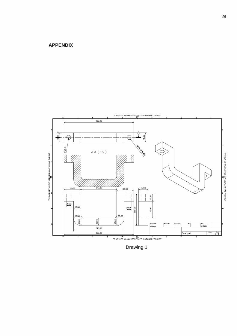
The down part holds (by welding) the plate that is responsible for the holding of
another member responsible for the cantilever load. It positions the whole member
at the accurate place. Details will be found in drawing 1 in appendix.

20
Figure 7. Down part.
The front plate (figure 8.) serves as an intermediary to transfer the load (tension
force) from the attachment to the axle. It is a tension member. Details will be found
in drawing 3 in appendix.
Figure 8. Front plate.

21
Assembly 1 (figure 9.) shows how all the three parts will be joined together before
the one that will act as chassis will be bolted to it which also has another support
towards the end part.
Figure 9.
Back plate (Figure 10) will also act as a support at the rear end to counter the
tension force that will act on front support. It will act as a compression member.
Details will be found in drawing 2 in appendix.

22
Figure 10. Back plate.
The chassis member (figure 11.) will be bolted to both front and rear plate to carry
the load of the equipment. This current picture shows how the old one will be
reshaped into this format.
The old one’s shape has to be changed to this shape for the on-coming equipment
to fit in properly to facilitate the assembling process. Details will be found in drawing
5 in appendix.
Figure 11. Chassis member.

23
At this juncture, the full assembly of the whole part can be seen in figure 12. This
picture gives a full diagrammatical description of the whole system.
Figure 12. Full assembly.
The same method is also applicable to the second part but there is also a fuel tank
which makes the shapes of the component parts to be different.
The pictures of the second part of the system are shown in figures 13-15. The
difference in shapes is caused by the presence of the fuel tank and the shape of
chassis which has to be taken into consideration. Details will be found in drawings
7, 8 and 6 respectively in appendix.

24
Figure 13. Upper tank with tank.
Figure 14. Lower part with tank.

25
Figure 15. Chassis member with tank.

26
5. CONCLUSION
As the target point was discussed in chapter one, using a simple graph to analyse
how the efficiency of the equipment and cost/time taken for the process made it
easier and served as guide. Before the abandoned equipment can be set back to
life, those stages mentioned were followed and mastered. Putting all the
components together and comparing and contrasting all the solutions available
made the project went well. The pre-determined target area which was found to be
a place with high efficiency and minimum cost served as guide to follow. Also, by
modifying the old equipment to suit current use falls within the target area which
made it to be the chosen one. The price of new equipment ranges from fifteen
thousands to twenty-five thousands Euros depending on the maker and the model
number but this modification system takes off up to sixty-five percent of the price
which makes it affordable for a good manager. In addition, it was seen that this
project really improved my skills and gave me confidence to tackle any type of other
designing work to some extends.

27
References
1. Timings, R. L. and S. P. Wilkinson.
Manufacturing technology Vol. 2, Second edition, 2000.
2. Timings, R. L.
Manufacturing technology Vol.1, First edition, 1990
3. Brown, James.
Advanced machining technology, First edition, 1998
4. http://www.3dscanco.com/about/3d-scanning/
Searched date: 25.03.2010
5. www.isbalanssi.com
Searched date: 20.03.2010
28
APPENDIX
Drawing 1.

29
Drawing 2.

30
Drawing 3.

31
Drawing 4.

32
Drawing 5.

33
Drawing 6.

34
Drawing 7.

35
Drawing 8.