magnetic design considerations
DESCRIPTION
Magnetic Design Considerations. Transformers Used to step-up or step-down voltages Inductors Storage during energy transfer Carries a DC current while supplying current Need to avoid saturation of the core. Transformer Primary Voltage in Terms of Flux. Transformer Powers and Efficiency. - PowerPoint PPT PresentationTRANSCRIPT
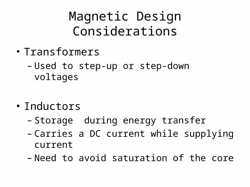
Magnetic Design Considerations
• Transformers– Used to step-up or step-down voltages
• Inductors– Storage during energy transfer– Carries a DC current while supplying current– Need to avoid saturation of the core
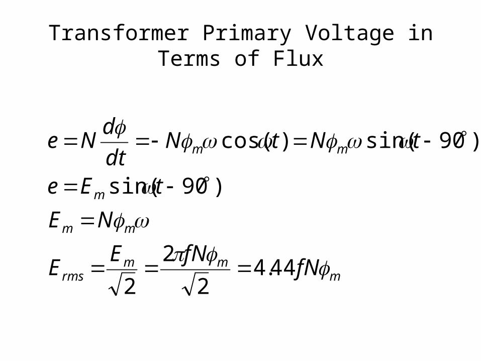
Transformer Primary Voltage in Terms of Flux
mmm
rms
mm
m
mm
fNfNE
E
NE
tEe
tNtNdt
dNe
44.42
2
2
)90sin(
)90sin()cos(
Transformer Powers and Efficiency
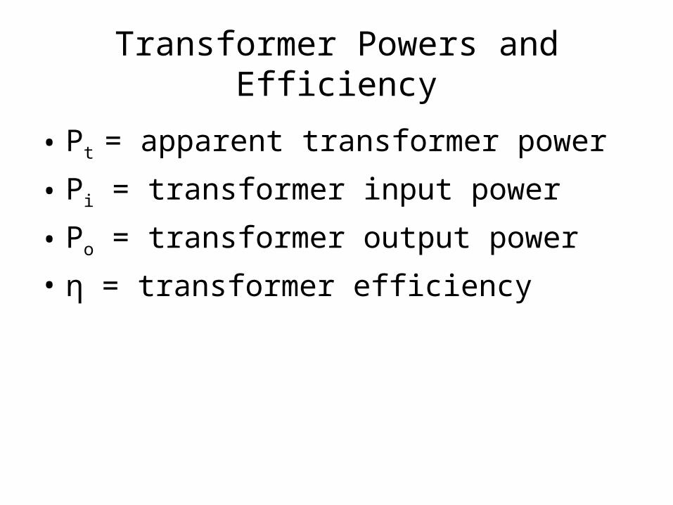
• Pt = apparent transformer power
• Pi = transformer input power
• Po = transformer output power
• η = transformer efficiency
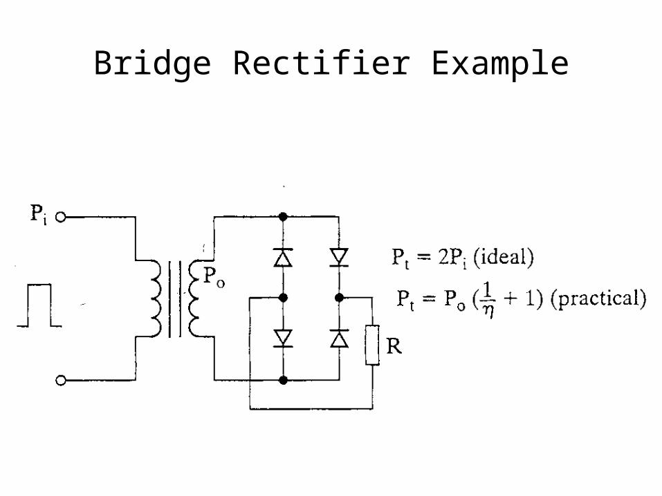
Bridge Rectifier Example
Analysis
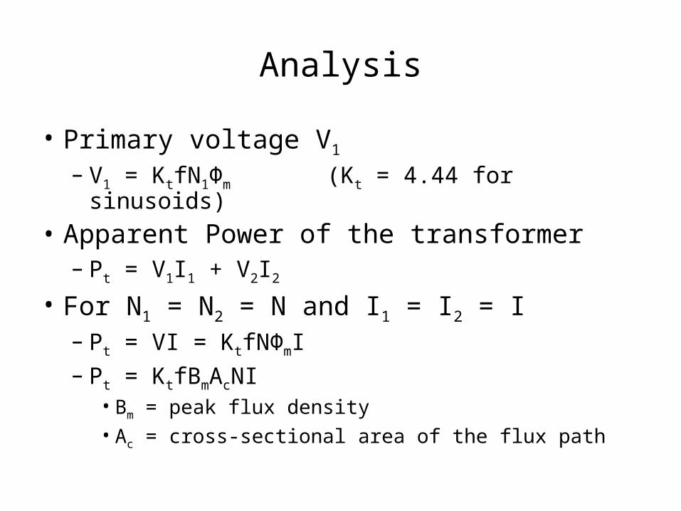
• Primary voltage V1
– V1 = KtfN1Φm (Kt = 4.44 for sinusoids)
• Apparent Power of the transformer– Pt = V1I1 + V2I2
• For N1 = N2 = N and I1 = I2 = I– Pt = VI = KtfNΦmI– Pt = KtfBmAcNI
• Bm = peak flux density• Ac = cross-sectional area of the flux path
Analysis (continued)
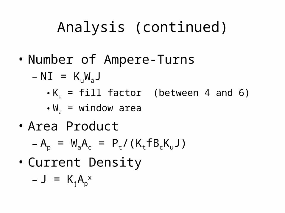
• Number of Ampere-Turns– NI = KuWaJ
• Ku = fill factor (between 4 and 6)
• Wa = window area
• Area Product– Ap = WaAc = Pt/(KtfBcKuJ)
• Current Density– J = KjAp
x
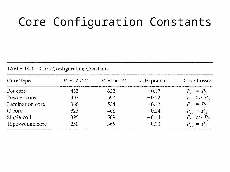
Core Configuration Constants
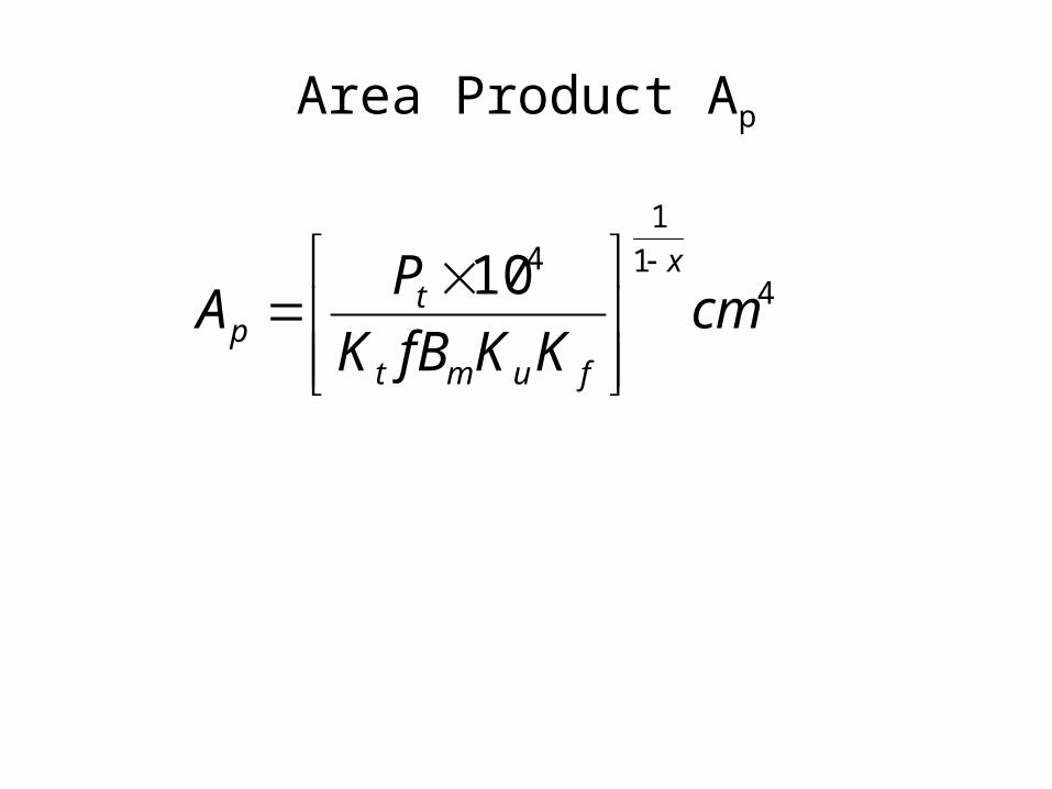
Area Product Ap
41
1410
cmKKfBK
PA
x
fumt
tp
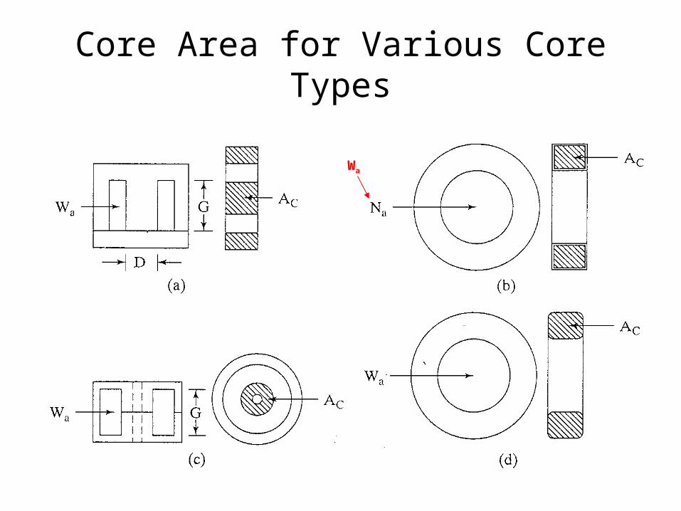
Core Area for Various Core Types
Wa
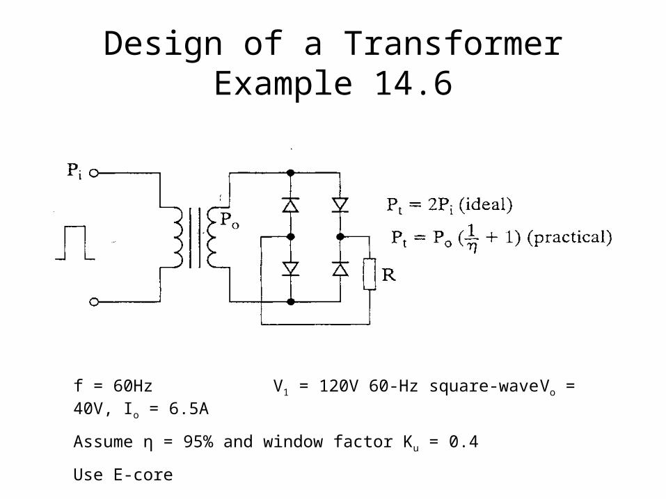
Design of a TransformerExample 14.6
f = 60Hz V1 = 120V 60-Hz square-wave Vo = 40V, Io = 6.5A
Assume η = 95% and window factor Ku = 0.4
Use E-core
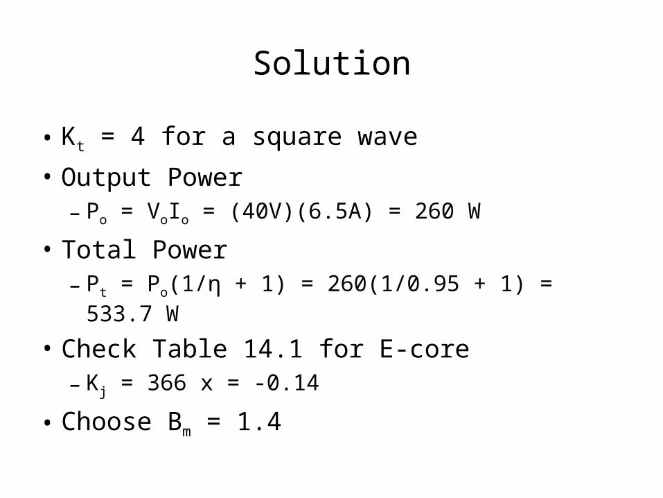
Solution
• Kt = 4 for a square wave
• Output Power– Po = VoIo = (40V)(6.5A) = 260 W
• Total Power– Pt = Po(1/η + 1) = 260(1/0.95 + 1) = 533.7 W
• Check Table 14.1 for E-core– Kj = 366 x = -0.14
• Choose Bm = 1.4
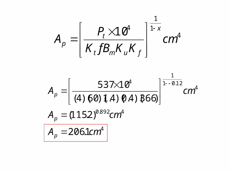
41
1410
cmKKfBK
PA
x
fumt
tp
4
4892.0
412.01
14
1.206
)2.115(
)366)(4.0)(4.1)(60)(4(
10537
cmA
cmA
cmA
p
p
p
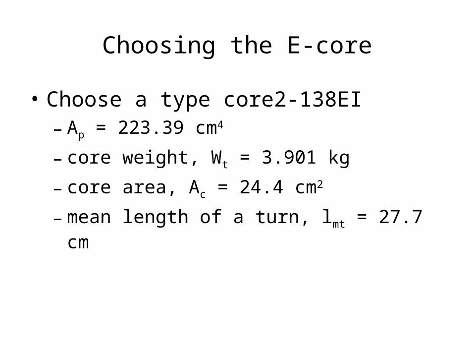
Choosing the E-core
• Choose a type core2-138EI– Ap = 223.39 cm4
– core weight, Wt = 3.901 kg
– core area, Ac = 24.4 cm2
– mean length of a turn, lmt = 27.7 cm
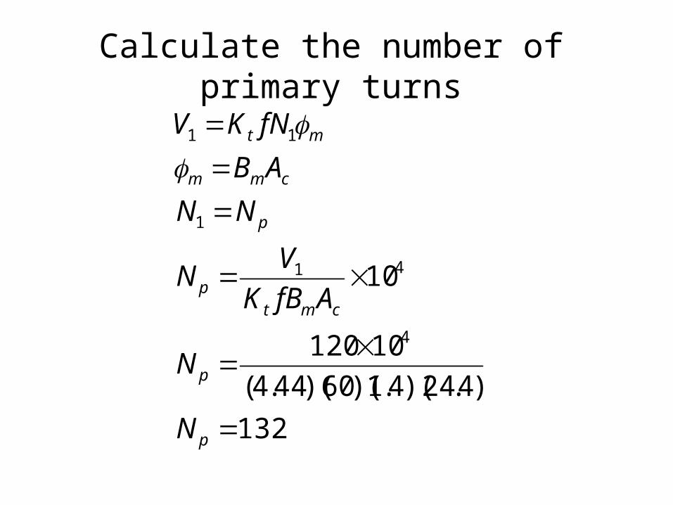
Calculate the number of primary turns
132
)4.24)(4.1)(60)(44.4(
10120
10
4
41
1
11
p
p
cmtp
p
cmm
mt
N
N
AfBK
VN
NN
AB
fNKV
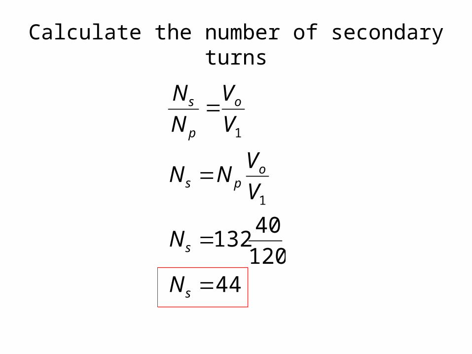
Calculate the number of secondary turns
44120
40132
1
1
s
s
ops
o
p
s
N
N
V
VNN
V
V
N
N
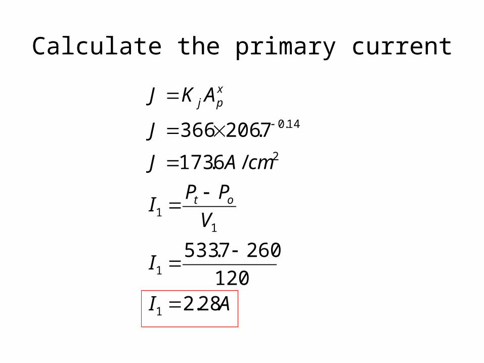
Calculate the primary current
AI
I
V
PPI
cmAJ
J
AKJ
ot
xpj
28.2120
2607.533
/6.173
7.206366
1
1
11
2
14.0
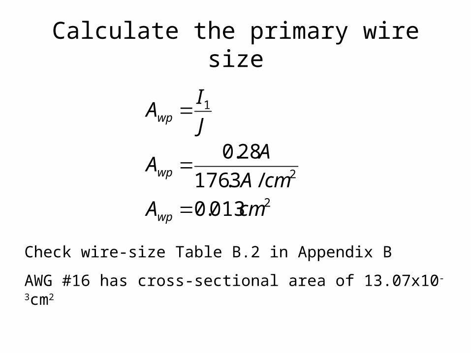
Calculate the primary wire size
2
2
1
013.0
/3.176
28.0
cmA
cmA
AA
J
IA
wp
wp
wp
Check wire-size Table B.2 in Appendix B
AWG #16 has cross-sectional area of 13.07x10⁻³cm2
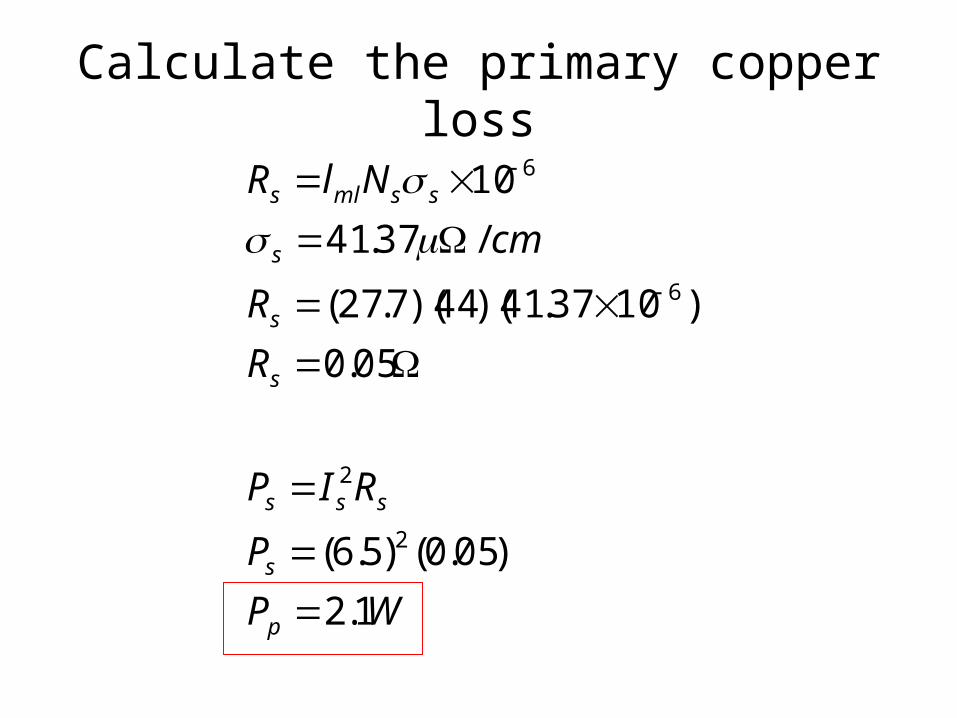
Calculate the primary copper loss
WP
P
RIP
R
R
cm
NlR
p
s
sss
s
s
s
ssmls
1.2
)05.0()5.6(
05.0
)1037.41)(44)(7.27(
/37.41
10
2
2
6
6
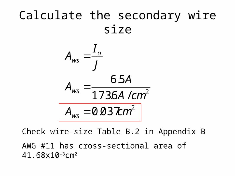
Calculate the secondary wire size
2
2
037.0
/6.173
5.6
cmA
cmA
AA
J
IA
ws
ws
ows
Check wire-size Table B.2 in Appendix B
AWG #11 has cross-sectional area of 41.68x10⁻³cm2
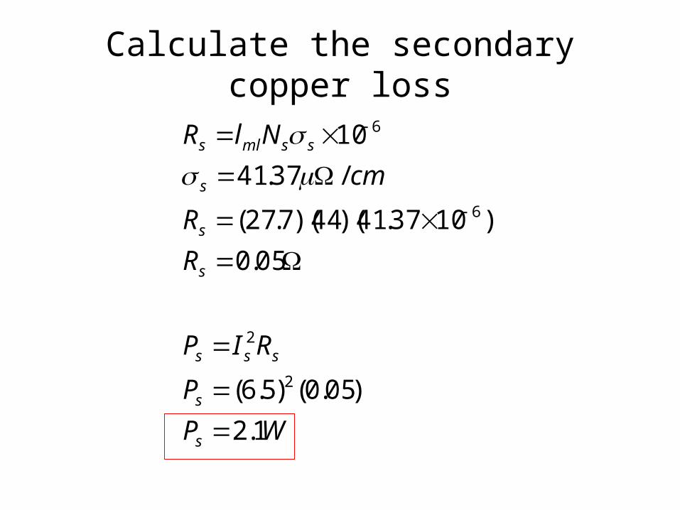
Calculate the secondary copper loss
WP
P
RIP
R
R
cm
NlR
s
s
sss
s
s
s
ssmls
1.2
)05.0()5.6(
05.0
)1037.41)(44)(7.27(
/37.41
10
2
2
6
6
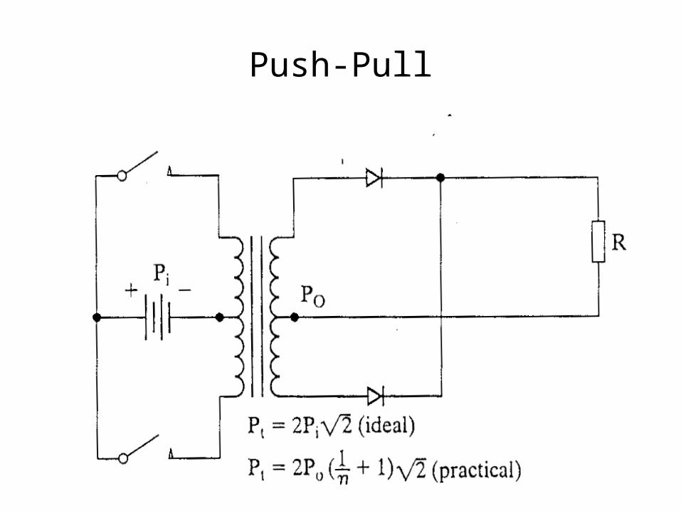
Push-Pull
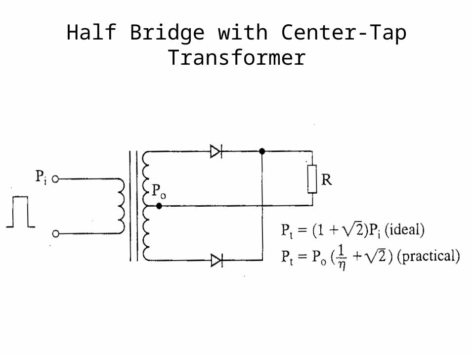
Half Bridge with Center-Tap Transformer
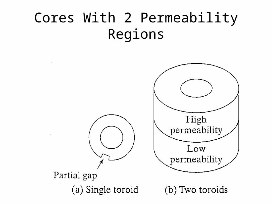
Cores With 2 Permeability Regions