mdsm/rtg88 - farnell
TRANSCRIPT
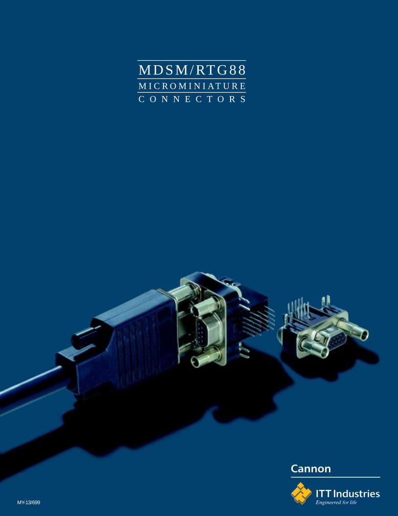
MDSM/RTG88M I C R O M I N I AT U R E
C O N N E C T O R S
MY-13/699

Subject to change
Contents
MICRO MDSMShielded connectors ................................................................................................................................... 3Doubledecker .................................................................................................................................................. 6Contacts .......................................................................................................................................................... 8Locking devices ............................................................................................................................................. 9MDSM with straight solder pins ................................................................................................................ 10MDSM with crimp contacts, for panel mounting .................................................................................. 12Cables ................................................................................................................................................. .................. 14Tools ...................................................................................................................................................................... 14
Product Safety Information....................................................................................................................... 15

3
Technical Data
Insulator Thermoplast, UL94V-0Contact guiding plate PA, high temperature resistantShell Steel, tinned and nickel platedContacts Copper alloyContact finish Gold over PdNiContact termination area Tin (SnPb)Wire size AWG 28 – 26Insulation dia. 0.95 mm maxContact spacing 1.27 mmContact number 9, 15, 25Temperature rangeacc. DIN IEC 68 Part 1 –55 / 125°C
Electrical Data
Current rating 2.5 A / 25°CTest voltage 350 VrmsContact resistance 20 mΩ max (crimp version)
35 mΩ max (pcb version)Insulation resistance 5000 MΩ min
Shielding Effectiveness
Frequency MHz Attenuation dB10 5630 47159 34500 26750 221000 19
MICRO MDSM
Shielded Connectors
MICRO MDSM is the Cannon designation for ashielded interface connector in its Micromini-ature series. It is ideally suited for applicationswith specific requirements to the shielding, e.g.components for telecommunications and com-puters.
The MDSM connector is suitable for modernsolder methods, e.g. IR reflow and vapor phasesoldering. It is available with crimp contacts(sockets only) as a cable connecting receptacle.Or with 90° solder pins as a pcb connector. Thecontacts are spaced at 1.27 mm, the solder pinsat 1.27 x 2.54 mm. Different locking devices areavailable – see page 9.

Subject to change4
Order Reference
MDSM - 9 P E - Z7 - VR - *
Series
Number of contacts9, 15, 25
Contact typeP - PinS - Socket (with crimp termination only)
Termination methodC - Crimp termination (contacts to be ordered separately)E - Solder pin 90°, spacing 1,27 x 2,54 mm, with rivet nut and grounding tab
(Pin connector only)
Mounting methodZ7 - Locking screw 1)Z10 - Screw for wall thickness 1,5 mm 1)Z11 - Screw, long, blank 2)Z12 - Screw for wall thickness 1,0 mm 1)Z24 - Push pull 2)Z33 - Locking screw, short 1)Z34 - Screw, short, for wall thickness 1,5 mm 1)Z35 - Screw, short, for wall thickness 1,0 mm 1)Z41 - Locking screw 1)Z42 - Screw, for wall thickness 1,5 mm 1)Z43 - Screw, for wall thickness 1,0 mm 1)
PackagingVR - Tube packaging (not for termination method C)VS1 - 100 pieces
ModificationPlease consult factory
1) for pin connectors only2) for socket connectors only (cable connecting receptacle)
Tube packaging (VR)A tube contains the following numbers of MDSM connectors:
No. of contacts No. of connectors9 2515 2225 17
Ordering MDSM connectorsTube loaded connectors can only be supplied in the quantityper tube shown above or in multiples thereof. Other quantitiescannot be supplied.This also applies when ordering VS1.
MICRO MDSM
Shielded Connectors

5
Cable Connector
Socket contacts see page 8
No of Designation Dimensionscontacts A max B ± 0,1 C ± 0,1 D ± 0,29 MDSM-9SC-Z11-VS1 MDSM-9SC-Z24-VS1 19,9 14,35 9,45 815 MDSM-15SC-Z11-VS1 MDSM-15SC-Z24-VS1 23,7 18,16 13,25 825 MDSM-25SC-Z11-VS1 MDSM-25SC-Z24-VS1 30,05 24,5 19,6 8
PCB Connector 90°
with pin contacts
No of Designation Dimensionscontacts A max B C max D max E F G (wall thickness)
-Z7 -Z10 -Z129 MDSM-9PE-Z*-VR25 19,9 14,35 8,6 9,0 5,08 10,24 0,00 1,5 1,015 MDSM-15PE-Z*-VR22 23,7 18,16 12,4 12,8 8,89 14,00 0,00 1,5 1,025 MDSM-25PE-Z*-VR17 30,05 24,5 18,8 19,15 15,24 20,35 0,00 1,5 1,0* indicate mounting method
MICRO MDSM

Subject to change6
MICRO MDSM
Technical Data
Insulator Thermoplast, UL94V-0Contact guiding plate PA, high temperature resistantShell Steel, tinned and nickel platedContacts Copper alloyContact finish Gold over PdNiContact termination area tinned (SnPb)Contact spacing 1.27 mmContact number 18, 30Temperature rangeacc. DIN IEC 68 Part 1 –55 / 125°C
Electrical Data
Current rating 2.5 A / 25°C (row 1, 2)1.8 A / 25°C (row 3, 4)
Test voltage 350 VrmsContact resistance 35 mΩ max (row 1, 2)
55 mΩ max. (row 3, 4)Insulation resistance 5000 MΩ min
Doubledecker
This connector version offers higher packagingdensity. The MDSM Doubledecker provides twicethe number of contacts in only 30% extra space.
Two Standard MDSM cable connectors with thecorresponding number of contacts mate with theMDSM Doubledecker. The MDSM Doubledeckeris available with pin contacts only.
0

7
Order Reference
MDSM - 18 P E - Z7 - VR
Series
Number of contacts18, 30
Contact typeP - Pin
Termination methodE - Solder pin 90°, spacing 1,27 x 2,54 mmwith rivet nut and grounding tab
Mounting method*Z7 - Locking screwZ10 - Screw for wall thickness 1,5 mmZ12 - Screw for wall thickness 1,0 mm* Additional mounting methods on page 9
PackagingVR - Tube packaging (not for termination method C)
Tube packaging (VR)A tube contains the following numbers of MDSMconnectors:
No. of contacts No. of connectors18 2530 22
Ordering MDSM connectorsTube loaded connectors can only be supplied in thequantity per tube shown in the table or in multiplesthereof. Other quantities cannot be supplied.
No of Designation Dimensionscontacts A max B C max D max E F G (Wall thickness)
-Z7 -Z10 -Z1218 MDSM-18PE-Z*-VR25 19,9 14,35 8,6 9,0 5,08 10,24 0,00 1,5 1,030 MDSM-30PE-Z*-VR22 23,7 18,16 12,4 12,8 8,89 14,00 0,00 1,5 1,0* indicate mounting method
MICRO MDSM
Doubledecker
0

Subject to change8
MICRO MDS/MDSM
on reels / 1000 pieces (TS)
MDS-P-TS Pin contactMDS-S-TS Socket contact
on reels / 10 000 pieces (RL)
MDS-P-RL Pin contactMDS-S-RL Socket contact
The contacts (1.2 mm PdNi with 0.1 µm Au over 0.5 µm Ni) are tin plated in the crimp area.Wire size AWG 28 – 26 (0.09 – 0.14 mm2).
Signal Contacts

9
MICRO MDSM
Screw locking
for cable connectors (socket side)Z11 Screw, long, blank
for pcb connectors (pin side)Z7 Locking screwZ10 Screw for wall thickness 1.5 mmZ12 Screw for wall thickness 1 mmZ33 Locking screw, shortZ34 Screw, short, for wall thickness 1.5 mmZ35 Screw, short, for wall thickness 1 mm
Push Pull
for cable connectors (socket side)Z24 Push pull
for pcb connectors (pin side)Z41 Locking pinZ42 Screw, for wall thickness 1.5 mmZ43 Screw, for wall thickness 1 mm

Subject to change10
Technical Data
Insulator Thermoplast, UL 94V-0Shell Steel, tinned and nickel platedContacts Copper alloyContact finish Gold over PdNiContact termination tinnedWire size AWG 28 – 26Contact spacing 1,27 mmContact number 9Temperature rangeacc to DIN IEC 68 part 1 –55 / 125°C
Electrical Data
Current rating 1,5 A / 55°CVoltage rating 350 VrmsContact resistance 20 mΩ maxInsulation resistance 5000 MΩ
with straight solder pins
Due to customer requirements connectorsMDSM-9PE-Z** with 90° termination are notsuitable for all applications. There is great in-terest for a MDSM version with straight ter-minations. To fulfill market requirements thefollowing connector versions and tools weredevelopped:
MDSM-9PA-Z7/Z10 and MDSM-9PA-Z41/Z42with straight terminations and pcb locking.
Typical ApplicationsSSA band and disk drives, SSA distributionpanels, bar code readers, mobile telecommu-nications and medical equipment.
Locking of PC BoardThe mating and unmating forces are concen-trated on to an integrated PCB locking, after theconnector has been mounted on a pc board.
Please note:The standard screw locking which is being usedfor MDSM-9PE-Z10 do not apply to MDSMA-9PA..
The MDSM-9PA screws require a shorter thread.
MICRO MDSM
MDSM-9PA Connector optionally with push-pull or screw locking

11
MICRO MDSM
Dimensions
Mounting Methods

Subject to change12
MICRO MDSM
with crimp contacts, for panel mounting
The market shows great interest for a MDSMInline receptacle with pin contacts for crimptermination. To fulfill this requirements thefollowing connector versions and tools havebeen developped to accomodate pin contactscrimped to wire sizes AWG 28 – 26:
- MDSM-9PC-Z7/Z10-O- VS1- MDSM-9PC-Z42-O-VS1
ContactsContacts MDS-P-TS (1000 contacts / reel) orMDS-P-RL (10.000 contacts / reel) to be orderedseparately.
MDSM-9PC Connector with screw locking
Technical Data
Insulator Thermoplast, UL 94V-0Shell Steel, tinned and nickel platedContacts Copper alloyContact finish Gold over PdNiContact termination tinnedWire size AWG 28 – 26Contact spacing 1,27 mmContact number 9Temperature rangeacc to DIN IEC 68 part 1 –55 / 125°C
Electrical Data
Current rating 2,0 A / 55°CVoltage rating 350 VeffContact resistance 20 mΩ maxInsulation resistance 5000 MΩ

13
MICRO MDSM
Dimensions
Panel Cutout

Subject to change14
MDSM
Stranded wireConductors Copper, tinned
AWG 26 / 7 x 0,160 mmAWG 28 / 7 x 0,127 mm
Insulation PVC, PP or HDPE, Outer dia. max. 0,9 mm
Wall thickness AWG 26: generally min. 0,140 mmAWG 28: generally min. 0,152 mm
for all: min. permissible thickness at any position .127 mm
CableShielding Shielding braid, tinned copper, coverage min. 80%
Insulation PVC
Wall thickness 0.56 mm min. at any position*0.76 mm min. at any position**
Outer diameter Strands Outer diameter mm max.9 5,715 6,725 7,9
Temperature range –40 / 80°C
Operating voltage 300 Vrms
Test voltage 1000 Vrms min.
Conductor resistance 240 Ω/km
* Cable with 9 wires or 5 twisted pairs ** Cable with more than 9 wires or more than 5 twisted pairs
for connectors MDSM
Tooling Hand crimp tool (for reeled contacts) CCTR-MDSSemi-automatic stripper / crimper EPS 3500-MDSInsertion tool CT 120090-102
Other tools see assembly instruction
MICRO – Round Cable

Subject to change18
THIS NOTE SHOULD BE READ IN CONJUNCTIONWITH THE PRODUCT DATA SHEET/CATALOGUE.FAILURE TO OBSERVE THE ADVICE IN THIS INFOR-MATION SHEET AND THE OPERATING CONDITIONSSPECIFIED IN THE PRODUCT DATA SHEET/CATALOGUE COULD RESULT IN HAZARDOUSSITUATIONS.
1. MATERIAL CONTENT AND PHYSICALFORMElectrical connectors do not usually containhazardous materials. They contain conducting andnon-conducting materials and can be divided intotwo groups.
a) Printed circuit types and low cost audio typeswhich employ all plastic insulators and casings.
b) Rugged, Fire Barrier and High Reliability typeswith metal casings and either natural rubber,synthetic rubber, plastic or glass insulatingmaterials.
Contact materials vary with type of connector andalso application and are usually manufactured fromeither copper, copper alloys, nickel, alumel, chromelor steel. In special applications, other alloys maybe specified.
2. FIRE CHARACTERISTICS AND ELECTRICSHOCK HAZARDThere is no fire hazard when the connector iscorrectly wired and used within the specifiedparameters. Incorrect wiring or assembly of theconnector or careless use of metal tools orconductive fluids, or transit damage to any of thecomponent parts may cause electric shock orburns. Live circuits must not be broken by sepa-rating mated connectors as this may cause arcing,ionisation and burning.Heat dissipation is greater at maximum resistancein a circuit. Hot spots may occur when resistanceis raised locally by damage, e.g. cracked ordeformed contacts, broken strands of wire. Localoverheating may also result from the use of theincorrect application tools or from poor qualitysoldering or slack screw terminals. Overheating mayoccur if the ratings in the Product Data Sheet/Catalogue are exceeded and can cause breakdownof insulation and hence electric shock.If heating is allowed to continue it intensifies byfurther increasing the local resistance through lossof temper of spring contacts, formation of oxidefilm on contacts and wires, and leakage currentsthrough carbonisation of insulation and trackingpaths. Fire can then result in the presence ofcombustible materials and this may release noxiousfumes. Overheating may not be visually apparent.Burns may result from touching overheatedcomponents.
3. HANDLINGCare must be taken to avoid damage to anycomponent parts of electrical connectors duringinstallation and use. Although there are normallyno sharp edges, care must be taken when handlingcertain components to avoid injury to fingers.
ITT Cannon manufactures the highest quality products available in the marketplace; however these products are intendedto be used in accordance with the specifications in this catalog. Any use or application that deviates from stated operatingspecifications is not recommended and may be unsafe. No information and data contained in this catalog shall be construedto create any liability on the part of Cannon. Any new issue of this catalog shall automatically invalidate and supersedeany and all previous issues. A limited warranty applies to Cannon products. Except for obligations assumed by Cannonunder this warranty, Cannon shall not be liable for any loss, damage, cost of repairs, incidental or consequentialdamages of any kind, whether or not based on express or implied warranty, contract, negligence or strict liabilityarising in connection with the design, manufacture, sale, use or repair of the products. Product availability, prices anddelivery dates are exclusively subject to our respective order confirmation form; the same applies to orders based ondevelopment samples delivered. This catalog is not be construed as an offer. It is intended merely as an invitation to makean offer. By this publication, Cannon does not assume responsibility or any liability for any patent infringements or otherrights of third parties which may result from its use. Reprinting this catalog is generally permitted, indicating the source.However, Cannon's prior consent must be obtained in all cases.
Cannon is a trademark of ITT Industries, Inc
Electrical connectors may be damaged in transit tothe customers, and damage may result in creationof hazards. Products should therefore be examinedprior to installation/use and rejected if found to bedamaged.
4. DISPOSALIncineration of certain materials may releasenoxious or even toxic fumes.
5. APPLICATIONConnectors with exposed contacts should not beselected for use on the current supply side of anelectrical circuit, because an electric shock couldresult from touching exposed contacts on anunmated connector. Voltages in excess of 30 V acor 42.5 V dc are potentially hazardous and careshould be taken to ensure that such voltages cannot be transmitted in any way to exposed metal partsof the connector body. The connector and wiringshould be checked, before making live, to have nodamage to metal parts or insulators, no solder blobs,loose strands, conducting lubricants, swarf, or anyother undesired conducting particles. Insulationresistance should be checked to make certain thatno low resistance joints or spurious conducting pathare existing between contacts and exposed metalparts of the connector body. Further the contactresistance of the connectors should be measuredwithin the electrical circuit in order to identify highresistances which result in excessive connectorheating.
Always use the correct application tools as specifiedin the Data Sheet/Catalogue.
Do not permit untrained personnel to wire, assembleor tramper with connectors.
For operation voltage please see appropriate nationalregulations.
IMPORTANT GENERAL INFORMATION.1. Air and creepage paths/Operating voltage
The admissible operating voltages depend on theindividual applications and the valid national andother applicable safety regulations.
For this reason the air and creepage path dataare only reference values. Observe reduction of airand creepage paths due to PC board and/or harness-ing.
2. TemperatureAll information given are temperature limits. Theoperation temperature depends on the individualapplication.
3. Other important informationCannon continuously endeavours to improve theirproducts. Therefore, Cannon products may deviatefrom the description, technical data and shape asshown in this catalogue and data sheets.
4. Harnessing and Assembly InstructionsIf applicable, our special harnessing and/or assem-bly instruction has to be adhered to. This is provid-ed at request.
Product Safety Information

Cannon Worldwide Facilities
AustriaAfrikanergasse 31020 ViennaFAX: (1) 2160948 PH: (1) 2160947BeneluxRue Col. Bourg Str. 105A1140 Brussels, BelgiumFAX: (02) 7269201 PH: (02) 726 75 94NLFAX: 31.35.691.8796 PH: 31.35.691.6855ChinaNo. 24, 2 BlockTaohuawu New DistrictZhenjiang, JiangsuP.R.C.FAX: 86 511 4428616 PH: 86 511 443 3399DenmarkPark Allé 287 A2605 BrøndbyFAX: 43 43 58 58 PH: 43 45 52 88FinlandVirkatie 11510 VantaaFAX:+358 9 70039188 PH: +358 9 70039180France2, Ave Sablons Bouillants, B.P. 13377109 MeauxFAX: (1) 64 33 16 82 PH: (1) 60 24 51 51GermanyPostfach 11 20, 71365 WeinstadtCannonstrasse 1, 71384 WeinstadtFAX: (07151) 699217 PH: (07151) 699-0Hong Kong906 New World Office BuildingWest Wing, 20 Salisbury RoadTsim Sha Tsui, KowloonFAX: (852) 2369-5651 PH: (852) 2732-2720
ItalyVia Panzeri 1020123 MilanoFAX: (02) 8372036 PH: (02) 581801Japan5362-1, 5-chome, HibarigaokaZama-shi, Kanagawa 228FAX: 0462-57-1680 PH: 0462-57-2010Korea620, Changkang Bldg.#22, Dohwa-dong, Mapo-kuSeoulFAX: (02) 717 7330 PH: (02) 702 7111SpainEdificio Italia 1a plantaParque Empresarial San FernandoSan Fernando de Henares28831 MadridFAX: (34) 91 656 15 83 PH: (34) 91 656 03 11SwedenNorr Mälarstrand 64Jaktvarvet 111235 StockholmFAX: (46) 8 650 0072 PH: (46) 8 650 0071SwitzerlandHerzogenmühle 188304 WallisellenFAX: (01) 830-3104 PH: (01) 830-3888, 830-3613United KingdomJays Close, Viables EstateBasingstoke Hampshire RG22 4BAFAX: (01256) 323356 PH: (01256) 311200United States666 E. Dyer RoadSanta Ana, CA 92705-5612FAX: 714.628.2142 PH: 714.557.4700
© 1999 ITT Industries, Inc. Printed in Germany. All Rights Reserved.
INTERNEThttp://www.ittcannon.com