mech props of mats
TRANSCRIPT
8/12/2019 Mech Props of Mats
http://slidepdf.com/reader/full/mech-props-of-mats 1/12
EDEXCEL NATIONAL CERTIFICATE
UNIT 12 – ENGINEERING MATERIALS
OUTCOME 2
TUTORIAL 1 – MECHANICAL PROPERTIES
2. PROPERTIES AND EFFECTS OF PROCESSING
Mechanical properties: density, tensile strength, shear and compressive strength, hardness,
toughness, ductility, malleability, elasticity, brittleness: effects of forming processes and heat
treatment
Thermal properties: expansivity, thermal conductivity
Electrical and magnetic properties: resistivity, permeability, permittivity
Durability: corrosion resistance, solvent resistance, protection processes
Tests: destructive testing e.g. tensile, hardness, impact, ductility; non-destructive testing e.g.dye penetrant, ultrasonic, magnetic powder, visual and tactile inspection
The self assessment for this tutorial is in the form of separate assignments.
CONTENTS
1. INTRODUCTION
2. MECHANICAL PROPERTIES
• Density
• Ductility• Malleability
• Strength
• Elasticity
• Hardness
• Toughness/Brittleness
3. THE AFFECT OF PROCESSING and MANIPULATION ON METALS
• Manipulative processes.
• Casting
• Moulding• Material removal
• Non metallic examples
4. HEAT TREATMENT of CARBON STEELS
5. HEAT TREATMENT OF NON FERROUS METALS
© D.J.Dunn www.freestudy.co.uk 1

8/12/2019 Mech Props of Mats
http://slidepdf.com/reader/full/mech-props-of-mats 2/12
1. INTRODUCTION
Engineering components and structures are made from materials carefully selected for their
properties and cost. The properties we look for in materials are many. The following lists and
explains the important properties.
2. MECHANICAL PROPERTIES
DENSITY
Density is a very important concept. It is a figure that tells us how many kg of a uniform substance
is contained in a volume of 1 m3. The value for pure water is one of the best-known figures since
from the old definition that 1 kg was the mass of 1 dm 3 of water then since there are 1000 dm3 in a
the density must be 1000 kg per m3. This is written in engineering as 1000 kg/m3
In general density is defined as the ratio of mass to volume and is given the symbol ρ (Greek letter
rho). ρ =M/V
RELATIVE DENSITY
Often the density of substances is compared to that of water and this is the relative density. For
example Lead has a mass 11.34 larger than the mass of the same volume of water so the relativedensity is 11.34. The symbol used is d.
Relative density = d = Mass of a substance ÷ Mass of the same volume of water
If we take 1 m3 as our volume then d = Mass of 1 m3 of the substance ÷ 1000
d = Density of the substance ÷1000
SELF ASSESSMENT EXERCISE No.1
1. Lead has a density of 11340 kg/m3
. Calculate the volume of 12 kg.
2. Aluminium has a density of 2710 kg/ m3. Calculate the relative density.
3. Seawater has a relative density of 1.036. Calculate the density of sea water.
TABLE OF DENSITIES FOR MATERIALS
Material Density kg/m3 Material Density kg/m
Air 20 °C, 1 atm, dry 1.21Aluminium 2700
Balsa wood 120
Brick 2000
Copper 8900
Cork 250
Diamond 3300
Glass 2500
Gold 19300
Helium (0 °C, 1 atm) 0.178
Hydrogen (0°C, 1 atm) 0.090
Ice 917
Iron 7900
3
Lead 11300Mercury 13600
Nickel 8800
Oil (olive) 920
Oxygen (0 °C, 1 atm) 1.43
Platinum 21500
Silver 10500
Styrofoam 100
Tungsten 19300
Uranium 18700
Water 20 °C, 1 atm 998
20 °C, 50 atm 1000
seawater 20 °C, 1 atm 1024
© D.J.Dunn www.freestudy.co.uk 2
8/12/2019 Mech Props of Mats
http://slidepdf.com/reader/full/mech-props-of-mats 3/12
DUCTILITY
This is the ability to be drawn out into wire. Copper can be pulled out into a long thin wire because
it has a large degree of ductility. Cast iron cannot be pulled out in this way and has virtually no
ductility. This property is largely defined by the % elongation and% area reduction found in the
tensile test.
MALLEABILITY
This is the ability of a material to be beaten into thin sheet by hammering. Lead is especially
malleable and opposite to glass that has no malleability at all.
STRENGTH
This is the force at which the material will fail. Strength is normally given as the force per unit area
or STRESS. There are various ways that a material may fail.
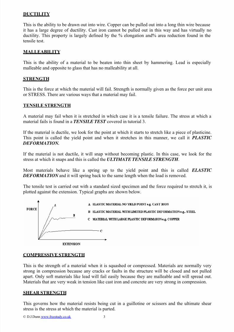
TENSILE STRENGTH
A material may fail when it is stretched in which case it is a tensile failure. The stress at which amaterial fails is found in a TENSILE TEST covered in tutorial 3.
If the material is ductile, we look for the point at which it starts to stretch like a piece of plasticine.
This point is called the yield point and when it stretches in this manner, we call it PLASTIC
DEFORMATION.
If the material is not ductile, it will snap without becoming plastic. In this case, we look for the
stress at which it snaps and this is called the ULTIMATE TENSILE STRENGTH .
Most materials behave like a spring up to the yield point and this is called ELASTIC
DEFORMATION and it will spring back to the same length when the load is removed.
The tensile test is carried out with a standard sized specimen and the force required to stretch it, is
plotted against the extension. Typical graphs are shown below.
COMPRESSIVE STRENGTH
This is the strength of a material when it is squashed or compressed. Materials are normally very
strong in compression because any cracks or faults in the structure will be closed and not pulled
apart. Only soft materials like lead will fail easily because they are malleable and will spread out.
Materials that are very weak in tension like cast iron and concrete are very strong in compression.
SHEAR STRENGTH
This governs how the material resists being cut in a guillotine or scissors and the ultimate shear
stress is the stress at which the material is parted.
© D.J.Dunn www.freestudy.co.uk 3
8/12/2019 Mech Props of Mats
http://slidepdf.com/reader/full/mech-props-of-mats 4/12
TORSIONAL STRENGTH
This governs the stress at which a material fails when it is twisted and a test similar to the tensile
test is carried out, only twisting the specimen instead of stretching it. This is a form of shearing.
ELASTICITY
The elasticity of materials governs how much they deform under loads. The main properties are:
Modulus of Elasticity E defined as the ratio of tensile stress to strain and determined in a tensile
test.
Modulus of Rigidity G defined as the ration of shear stress and strain and determined in a torsion
test.
Bulk Modulus K defined as the ration of pressure and volumetric strain and found with specialised
equipment for liquids.
Poisson’s ratio ν defined as the ratio of two mutually perpendicular strains and governs how the
dimensions of a material change such as reduction in diameter when a bar is stretched.
You should have studies these topics in other modules.
HARDNESS
This governs how a material resists being scratched and resists being worn away by rubbing. The
hardness is found with a hardness tester and there are many of these. The main ones are the Brinell,
the Vickers and the Rockwell test that basically consists of measuring how far a ball, cone or
pyramid can be pressed into the surface. Hard materials are diamonds and glass. Soft materials are
copper and lead. Hardness is measured by comparing it to the hardness of natural minerals and the
list is called the Moh scale. The list runs from 1 to 10 with 1 being the softest ands 10 the hardest.
10 Diamond
9 Corundum8 Topaz
7 Quartz
6 Feldspar
5 Apatite
4 Fluorite
3 Calcite
2 Gypsum
1 Talc
Hardness Testing is covered in the tutorial 3.
TOUGHNESS AND BRITTLENESS
Toughness is about how difficult it is to beak a material. Some materials are very strong but break
easily. These are brittle like glass and cast iron. Other materials are not very strong but take a lot of
energy and effort to part. Some polymers (plastics) are like this. Toughness is determined by
measuring the energy needed to fracture a specimen. This is done in special test machines that use a
swinging hammer to hit the specimen. The test also shows how susceptible the material is to
cracking by putting a small notch in the specimen for the crack to start from.
Notched bar tests are covered in tutorial 3
© D.J.Dunn www.freestudy.co.uk 4
8/12/2019 Mech Props of Mats
http://slidepdf.com/reader/full/mech-props-of-mats 5/12
3. THE AFFECT OF PROCESSING and MANIPULATION ON METALS
When a metal solidifies grains or crystals are formed. The grains may be small, large or long
depending on how quickly the material cooled and what happened to it subsequently. Heat
treatment and other processes carried out on the material will affect the grain size and orientation
and so dramatically affect the mechanical properties. In general slow cooling allows large crystals
to form but rapid cooling promotes small crystals. The grain size affects many mechanical
properties such as hardness, strength and ductility.
MANIPULATIVE PROCESSES
These are processes which shape the solid material by plastic deformation. If the process is carried
out at temperatures above the crystallisation temperatures, then re-crystallisation occurs and the
process is called HOT WORKING. Otherwise the process is called COLD WORKING. The
mechanical properties and surface finish resulting are very different for the two methods.
HOT ROLLING
This is used to produce sheets, bars and sections. If the rollers are cylindrical, sheet metal is
produced. The hot slab is forced between rollers and gradually reduced in thickness until a sheet ofmetal is obtained. The rollers may be made to produce rectangular bars, and various shaped beams
such as I sections, U sections, angle sections and T sections. Steel wire is also produced this way.
The steel starts as a round billet and passes along a line of rollers. At each stage the reduction
speeds up the wire into the next roller. The wire comes of the last roller at very high speeds and is
deflected into a circular drum so that it coils up. This product is then used for further drawing into
rods or thin wire to be used for things like springs, screws, fencing and so on.
COLD ROLLING
The process is similar to hot rolling but the metal is cold. The result is that the crystals are elongated
in the direction of rolling and the surface is clean and smooth. The surface is harder and the productis stronger but less ductile. Cold working is more difficult that hot working.
FORGING
In this process the metal is forced into shape by squeezing it between two halves of a die. The dies
may be shaped so that the metal is simply stamped into the shape required (for example producing
coins). The dies may be a hammer and anvil and the operator must manipulate the position of the
billet to produce the rough shape for finishing (for example large gun barrels).
COLD WORKING
Cold working a metal by rolling, coining, cold forging or drawing leaves the surface clean and
bright and accurate dimensions can be produced. If the metal is cold worked, the material within the
crystal becomes stressed (internal stresses) and the crystals are deformed. For example cold drawing
produces long crystals. In order to get rid of these stresses and produce “normal” size crystals, the
metal can be heated up to a temperature where it will re-crystallise. That is, new crystals will form
and large ones will reduce in size.
If the metal is maintained at a substantially higher temperature for a long period of time, the crystals
will consume each other and fewer but larger crystals are obtained. This is called “grain growth”.
Cold working of metals change the properties quite dramatically. For example, cold rolling or
drawing of carbon steels makes the stronger and harder. This is a process called “work hardening”.
© D.J.Dunn www.freestudy.co.uk 5
8/12/2019 Mech Props of Mats
http://slidepdf.com/reader/full/mech-props-of-mats 6/12
HOT WORKING
Most metals (but not all) can be shaped more easily when hot. Hot rolling, forging, extrusion and
drawing is easier when done hot than doing it cold. The process produces oxide skin and scale on
the material and producing an accurate dimension is not possible.
Hot working, especially rolling, allows the metal to re-crystallise as it is it is produced. This means
that expensive heat treatment after may not be needed. The material produced is tougher and more
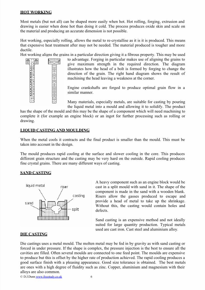
ductile.Hot working aligns the grain
ngine crankshafts are forged to produce optimal grain flow in a
any materials, especially metals, are suitable for casting by pouring
s in a particular direction giving it a fibrous property. This may be used
to advantage. Forging in particular makes use of aligning the grains to
give maximum strength in the required direction. The diagram
illustrates how the head of a bolt is formed by forging to change the
direction of the grain. The right hand diagram shows the result of
machining the head leaving a weakness at the corner.
© D.J.Dunn www.freestudy.co.uk 6
E
similar manner.
Mthe liquid metal into a mould and allowing it to solidify. The product
has the shape of the mould and this may be the shape of a component which will need machining to
complete it (for example an engine block) or an ingot for further processing such as rolling or
drawing.
LIQUID CASTING AND MOULDING
When the metal cools it contracts and the final product is smaller than the mould. This must be
taken into account in the design.
The mould produces rapid cooling at the surface and slower cooling in the core. This producesdifferent grain structure and the casting may be very hard on the outside. Rapid cooling produces
fine crystal grains. There are many different ways of casting.
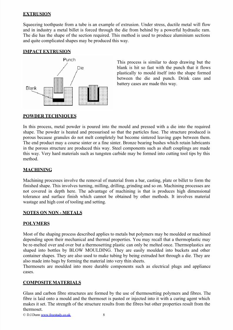
SAND CASTING
A heavy component such as an engine block would be
cast in a split mould with sand in it. The shape of the
component is made in the sand with a wooden blank.
Risers allow the gasses produced to escape and
provide a head of metal to take up the shrinkage.
Without this, the casting would contain holes and
defects.
Sand casting is an expensive method and not ideally
suited for large quantity production. Typical metals
used are cast iron. Cast steel and aluminium alloy.
DIE CASTING
Die castings uses a metal mould. The molten metal may be fed in by gravity as with sand casting or
forced in under pressure. If the shape is complex, the pressure injection is the best to ensure all the
cavities are filled. Often several moulds are connected to one feed point. The moulds are expensiveto produce but this is offset by the higher rate of production achieved. The rapid cooling produces a
good surface finish with a pleasing appearance. Good size tolerance is obtained. The best metals
are ones with a high degree of fluidity such as zinc. Copper, aluminium and magnesium with their
alloys are also common.

8/12/2019 Mech Props of Mats
http://slidepdf.com/reader/full/mech-props-of-mats 7/12
CENTRIFUGAL CASTING
This is similar to die casting. Several moulds are connected to one feed point and the whole
assembly is rotated so that the liquid metal is forced into the moulds. This method is especially
useful for shapes such as rims or tubes. Gear blanks are often produced this way.
INVESTMENT CASTING
In this process, wax shapes are first made in a metal mould. The shape is then coated with a ceramicmaterial. The wax is melted leaving a ceramic mould. After the metal is poured, the mould is
broken to release the casting. The advantage of this is that metals with a very high melting
temperature may be cast (e.g. turbine blades). These metals would destroy ordinary die casting
moulds very quickly. Excellent dimensional tolerance is produced.
DRAWING
In this process, a metal billet is pulled through a die. The hole in the die has the shape of the
finished section. This process is used to produce copper wire, seamless steel or copper tubing and so
on. Hot rolled steel wire may also be used for further drawing as described earlier. Cold drawing
produces work hardening and it may be necessary to anneal the metal at some stage.
The term DEEP DRAWING is applied to the process of punching a sheet material into a cup shape
as shown below. The metal is drawn into the die by the punch.
If the blank is clamped around the edge, the process becomes a PRESSING.
The blank is pressed into the shape, of the die by
the rubber pad. This is used to produces car body
panels and cooking pans.
SPINNING
© D.J.Dunn www.freestudy.co.uk 7
In this process the blank is held
against the former and the whole
assembly is spun. The blank is the
forced into the shape of the former
by forcing a forming tool against it.
This method is used to produce
aluminium satellite dishes, cooking
pans and so on. The process is not best suited to large volume
production.
8/12/2019 Mech Props of Mats
http://slidepdf.com/reader/full/mech-props-of-mats 8/12
EXTRUSION
Squeezing toothpaste from a tube is an example of extrusion. Under stress, ductile metal will flow
and in industry a metal billet is forced through the die from behind by a powerful hydraulic ram.
The die has the shape of the section required. This method is used to produce aluminium sections
and quite complicated shapes may be produced this way.
IMPACT EXTRUSION
This process is similar to deep drawing but the
blank is hit so fast with the punch that it flows
plastically to mould itself into the shape formed
between the die and punch. Drink cans and
battery cases are made this way.
POWDER TECHNIQUES
In this process, metal powder is poured into the mould and pressed with a die into the required
shape. The powder is heated and pressurised so that the particles fuse. The structure produced is
porous because granules do not melt completely but become sintered leaving gaps between them.
The end product may a course sinter or a fine sinter. Bronze bearing bushes which retain lubricants
in the porous structure are produced this way. Steel components such as shaft couplings are made
this way. Very hard materials such as tungsten carbide may be formed into cutting tool tips by this
method.
MACHINING
Machining processes involve the removal of material from a bar, casting, plate or billet to form the
finished shape. This involves turning, milling, drilling, grinding and so on. Machining processes are
not covered in depth here. The advantage of machining is that is produces high dimensional
tolerance and surface finish which cannot be obtained by other methods. It involves material
wastage and high cost of tooling and setting.
NOTES ON NON - METALS
POLYMERS
Most of the shaping process described applies to metals but polymers may be moulded or machined
depending upon their mechanical and thermal properties. You may recall that a thermoplastic may
be re-melted over and over but a thermosetting plastic can only be melted once. Thermoplastics are
shaped into bottles by BLOW MOULDING. They are easily moulded into buckets and other
container shapes. They are also used to make tubing by being extruded hot through a die. They are
also made into bags by forming the material into very thin sheets.
Thermosets are moulded into more durable components such as electrical plugs and appliance
cases.
COMPOSITE MATERIALS
Glass and carbon fibre structures are formed by the use of thermosetting polymers and fibres. The
fibre is laid onto a mould and the thermoset is pasted or injected into it with a curing agent which
makes it set. The strength of the structure results from the fibres but other properties result from the
thermoset.© D.J.Dunn www.freestudy.co.uk 8

8/12/2019 Mech Props of Mats
http://slidepdf.com/reader/full/mech-props-of-mats 9/12
4. HEAT TREATMENT OF STEEL
The mechanical properties of materials can be changed by heat treatment. Let’s first examine how
this applies to carbon steels.
CARBON STEELS
In order to understand how carbon steels are heat treated we need to re-examine the structure. Steels
with carbon fall between the extremes of pure iron and cast iron and are classified as follows.
NAME CARBON % TYPICAL APPLICATION
Dead mild 0.1 – 0.15 pressed steel body panels
Mild steel 0.15 – 0.3 steel rods and bars
Medium carbon steel 0.5 – 0.7 forgings
High carbon steels 0.7 – 1.4 springs, drills, chisels
Cast iron 2.3 – 2.4 engine blocks
STRUCTURE
All metals form crystals when they cool down and change from liquid into a solid. In carbon steels,
the material that forms the crystals is complex. Iron will chemically combine with carbon to form
IRON CARBIDE (Fe3C). This is also called CEMENTITE. It is white, very hard and brittle. The
more cementite the steel contains, the harder and more brittle it becomes. When it forms in steel, it
forms a structure of 13% cementite and 87% iron (ferrite) as shown. This structure is called
PEARLITE. Mild steel contains crystals of iron (ferrite) and pearlite as shown. As the % carbon is
increased, more pearlite is formed and at 0.9% carbon, the entire structure is pearlite.
If the carbon is increased further, more cementite is formed and the structure becomes pearlite and
cementite as shown.
© D.J.Dunn www.freestudy.co.uk 9

8/12/2019 Mech Props of Mats
http://slidepdf.com/reader/full/mech-props-of-mats 10/12
HEAT TREATMENT of CARBON STEELS
Steels containing carbon can have their properties (hardness, strength, toughness etc) changed by
heat treatment. Basically if it is heated up to red hot and then cooled very rapidly the steel becomes
harder. Dead mild steel is not much affected by this but a medium or high carbon steel is.
When the steel is heated up to 700oC the carbon starts to dissolve in the iron like salt does in water.
This produces a uniform structure called AUSTENITE. As the temperature increases, the process
continues until at some higher temperature the structure is all austenite. The temperatures at which
this process starts and ends are called the lower and higher critical points. The upper critical point
changes with %C as shown on the diagram. Notice that above 0.83%C the upper and lower points
are the same. If the steel is cooled slowly, the reverse process occurs and cementite and pearlite
forms. The following are all forms of heat treatment.
Hardening• • • •
Annealing
Normalising
Tempering
HARDENING
If steel just hotter than the upper critical point is plunged into oil or water (quenching) the steel
cools very quickly. Instead of pearlite forming, a structure known as MARTENSITE is formed.
This is a very hard substance and the resulting steel is hard. The degree of hardness depends on how
fast it is cooled and water quenching is quicker than oil quenching. The graph shows the critical
temperature plotted against %C. For example 0.3 % carbon steel should be heated to a temperature
between 880 and 910oC.
TABLE OF HARDNESS OF QUENCHED STEELS
Carbon % 0.1 0.3 0.5 0.7 0.9 1.2
Brinell Hardness 150 450 650 700 680 690
ANNEALING
The purpose of annealing is to soften hard steel. The steel is heated slowly to the upper critical point
and held at this temperature for a time. It is then allowed to cool slowly. This process removes any
stresses trapped in the material due to quenching, machining or mechanical working (such as rolling
it).
TABLE OF ANNEALING TEMPERATURES RANGES FOR CARBON STEELS
Carbon % 0.12 0.12/0.25 0.3/0.5 0.5/0.9 0.9/1.3
Temperature oC 875/925 840/970 815/840 780/810 760/780
© D.J.Dunn www.freestudy.co.uk 10

8/12/2019 Mech Props of Mats
http://slidepdf.com/reader/full/mech-props-of-mats 11/12
NORMALISING
This is similar to annealing. When the steel has been kept hot for a long time (e.g. for forging), the
crystals become very large. When a cold steel has been mechanically worked, say by cold drawing
it into a bar, the crystals are elongated in one direction. Normalising returns the crystal structure to
normal and it is carried out by cooling the steel in air.
TEMPERING
The steel is heated up but not as high as the lower critical point. This allows some of the martensite
to change into pearlite. This softens the steel but also makes it tougher.
TABLE OF TYPICAL TEMPERING TEMPERATURES
Component Turning Drills Punches Cold Chisels Springs
Tools Milling Twist Drill
Temperature oC 230 240 260 280 300
SELF ASSESSMENT EXERCISE No.2
1. Describe the method of carburising.
2. What process would you use to harden
a) gear teeth
b) machine tool slideway
3. Describe the process of full annealing.
© D.J.Dunn www.freestudy.co.uk 11

8/12/2019 Mech Props of Mats
http://slidepdf.com/reader/full/mech-props-of-mats 12/12
5. HEAT TREATMENT OF OTHER METALS
The heat treatment methods for other metals and alloys are numerous and would need a vast amount
of study to cover them all. One important method worth studying is solution heat treatment and
aging.
SOLUTION HEAT TREATMENT AND AGING
When salt is dissolved in water, the maximum amount of salt that can be dissolved depends uponthe temperature. If the solution is saturated, then cooling causes the salt to precipitate out. Warming
allows more salt to dissolve. The same
principles apply to solid solutions but in
this case the molecules precipitating out
or being dissolved cannot move about
freely so the changes are much slower.
© D.J.Dunn www.freestudy.co.uk 12
Consider the case of an aluminium-
copper alloy. Part of the thermal
equilibrium diagram is shown below.
This shows that in going from 0 to548oC the amount of copper that can be
dissolved in aluminium increases from
0.2% to 5.7%
The light grey section contains an unsaturated solid solution. The dark grey portion contains the
maximum dissolved copper possible (saturated solution) and any more copper than these forms the
compound CuAl2. Consider the alloy known as Duralumin widely used in making skins for aircraft
and containers. This alloy contains 4% copper. Suppose the molten solution cools down very
slowly. First it will pass through the unsaturated portion and will eventually end up as a saturated
solution with excess copper.
At room temperature the structure will be as shown left with a background
of solid saturated solution with 0.2% Cu and the rest are particles of
compound containing the other 3.8% of the copper. The compound is a
hard and brittle substance so duralumin in this form is brittle.
Suppose we know heat up the alloy to point C. The compound gradually
dissolves into the solid solution (diffusion of atoms) as shown. At point B,
just below the melting temperature, all the copper is dissolved into the solid
solution with no compound at all. The alloy has to be kept at this
temperature long enough for the transformation to be complete. If the alloy
is now quenched in water for rapid cooling, the copper is trapped in the
solid solution and the solid solution is supersaturated. The quenched
structure is stronger and more ductile. This is known as SOLUTION
TREATMENT .
If the quenched duralumin is left at room temperature for a few days, the structure partially reverts
to the equilibrium condition and the strength and hardness increases and the ductility reduces. This
is called AGE HARDENING. This process may be accelerated by heating the alloy to 160 oC and
this is called PRECIPITATION HARDENING.