mirror actuation design for the interferometer … · mirror actuation design for the...
TRANSCRIPT

arX
iv:1
709.
0257
4v2
[ph
ysic
s.in
s-de
t] 3
Nov
201
7
Mirror actuation design for the interferometer
control of the KAGRA gravitational wave telescope
Yuta Michimura1, Tomofumi Shimoda1, Takahiro Miyamoto2,
Ayaka Shoda3, Koki Okutomi3,4, Yoshinori Fujii3, Hiroki
Tanaka2, Mark A. Barton3, Ryutaro Takahashi3, Yoichi Aso3,4,
Tomotada Akutsu3, Masaki Ando1,3,5, Yutaro Enomoto1,
Raffaele Flaminio3, Kazuhiro Hayama6, Eiichi Hirose2,6, Yuki
Inoue7,8, Takaaki Kajita2, Masahiro Kamiizumi6, Seiji
Kawamura6, Keiko Kokeyama6, Kentaro Komori1, Rahul
Kumar8, Osamu Miyakawa6, Koji Nagano2, Masayuki Nakano2,
Naoko Ohishi3, Ching Pin Ooi1, Fabian Erasmo Pena Arellano3,
Yoshio Saito6, Katsuhiko Shimode6, Kentaro Somiya9, Hiroki
Takeda1, Takayuki Tomaru8, Takashi Uchiyama6, Takafumi
Ushiba2, Kazuhiro Yamamoto10, Takaaki Yokozawa11, Hirotaka
Yuzurihara11
1 Department of Physics, University of Tokyo, Bunkyo, Tokyo 113-0033, Japan2 Institute for Cosmic Ray Research, University of Tokyo, Kashiwa, Chiba, 277-8582,
Japan3 National Astronomical Observatory of Japan, Mitaka, Tokyo, 181-8588, Japan4 SOKENDAI, The Graduate University for Advanced Studies, Hayama, Kanagawa
240-0193, Japan5 Research Center for the Early Universe, University of Tokyo, Bunkyo, Tokyo
113-0033, Japan6 KAGRA Observatory, Institute for Cosmic Ray Research, University of Tokyo,
Hida, Gifu 506-1205, Japan7 Institute of Physics, Academia Sinica, Nankang, Taipei 11529, Taiwan8 High Energy Accelerator Research Organization, Tsukuba, Ibaraki, 305-0801, Japan9 Department of Physics, Tokyo Institute of Technology, Ookayama, Meguro, Tokyo
152-8550, Japan10 Department of Physics, University of Toyama, Toyama, Toyama, 930-8555, Japan11 Department of Physics, Osaka City University, Sumiyoshi, Osaka 558-8585, Japan
E-mail: [email protected]
6 November 2017
Abstract. KAGRA is a 3-km cryogenic interferometric gravitational wave telescope
located at an underground site in Japan. In order to achieve its target sensitivity,
the relative positions of the mirrors of the interferometer must be finely adjusted with
attached actuators. We have developed a model to simulate the length control loops
of the KAGRA interferometer with realistic suspension responses and various noises
for mirror actuation. Using our model, we have designed the actuation parameters to

Mirror actuation design for interferometer control of KAGRA 2
have sufficient force range to acquire lock as well as to control all the length degrees
of freedom without introducing excess noise.
PACS numbers: 95.55.Ym, 07.60.Ly, 42.60.Da, 84.32.Hh, 07.10.Fq
Keywords: gravitational waves, cryogenic laser interferometer, vibration isolation, coil-
magnet actuator, lock acquisition
1. Introduction
The discovery of gravitational waves by Advanced LIGO has opened a brand new window
to our Universe [1]. To further enhance gravitational wave astronomy with better sky
localization, better sky coverage, and more precise parameter estimation [2, 3], it is
essential to extend the global network of advanced gravitational wave telescopes, with
detectors such as Advanced Virgo [4], KAGRA [5, 6, 7], and the third LIGO detector
in India [8].
KAGRA is a 3-km interferometric gravitational wave telescope located in the
Kamioka mine in Gifu Prefecture, Japan. Two unique features of KAGRA among
advanced interferometers are that it is constructed at a seismically quiet underground
site [9], and that it uses sapphire mirrors at cryogenic temperature to reduce thermal
noise [10, 11]. KAGRA was funded in 2010 and the tunnel excavation was started in
May 2012, which continued until the end of March 2014. In March 2016 the initial phase
of KAGRA, with a simple 3-km Michelson interferometer configuration, was operated
to test the basic performance at room temperature [12].
To operate an interferometric gravitational wave telescope with high sensitivity, the
relative positions of the mirrors must be finely tuned to maintain the resonant conditions
of the cavities. For this purpose, actuators are attached to the mirrors and various
locations in their suspension systems. Those actuators should have a wide enough force
range to keep the relative motion of the mirrors small enough, without introducing
excess noise into the gravitational wave signal. Minimizing the noise coming from the
actuators is essential for achieving the designed sensitivity, especially in the lower end
of the detector bandwidth, at a few tens of Hertz.
In this paper, we show noise and range calculations for designing the mirror
actuation used for the length control of the KAGRA interferometer. We start
by describing the overall interferometer configuration and the mirror suspension
configuration of KAGRA. We then describe our simulation model used to calculate the
noise and the range of the actuators. Finally, we present the results of our simulation to
show that our actuator design meets the displacement noise requirements for each mirror,
and has a wide enough force range for the length control of the KAGRA interferometer.
We also discuss the force range required for the lock acquisition of the interferometer.
Mirror actuation design for interferometer control of KAGRA 3
laser1064 nm
MCo
PRM
PR3
PR2
MCi
MCe
BS
ITMX ETMX
ITMY
ETMY
SR2
SRM
SR3
signalrecycling
cavity
3 k
m Y-arm cavity
to output optics
laser532 nm
X-arm cavity
powerrecycling
cavity
inputmode
cleaner
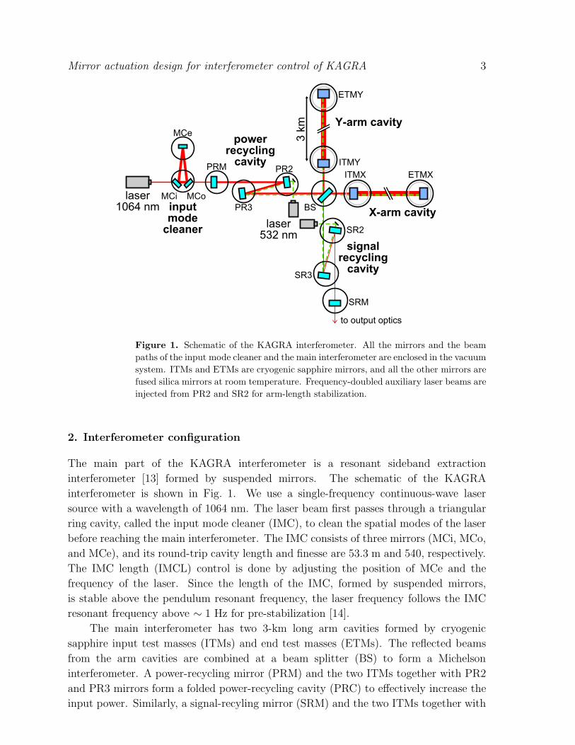
Figure 1. Schematic of the KAGRA interferometer. All the mirrors and the beam
paths of the input mode cleaner and the main interferometer are enclosed in the vacuum
system. ITMs and ETMs are cryogenic sapphire mirrors, and all the other mirrors are
fused silica mirrors at room temperature. Frequency-doubled auxiliary laser beams are
injected from PR2 and SR2 for arm-length stabilization.
2. Interferometer configuration
The main part of the KAGRA interferometer is a resonant sideband extraction
interferometer [13] formed by suspended mirrors. The schematic of the KAGRA
interferometer is shown in Fig. 1. We use a single-frequency continuous-wave laser
source with a wavelength of 1064 nm. The laser beam first passes through a triangular
ring cavity, called the input mode cleaner (IMC), to clean the spatial modes of the laser
before reaching the main interferometer. The IMC consists of three mirrors (MCi, MCo,
and MCe), and its round-trip cavity length and finesse are 53.3 m and 540, respectively.
The IMC length (IMCL) control is done by adjusting the position of MCe and the
frequency of the laser. Since the length of the IMC, formed by suspended mirrors,
is stable above the pendulum resonant frequency, the laser frequency follows the IMC
resonant frequency above ∼ 1 Hz for pre-stabilization [14].
The main interferometer has two 3-km long arm cavities formed by cryogenic
sapphire input test masses (ITMs) and end test masses (ETMs). The reflected beams
from the arm cavities are combined at a beam splitter (BS) to form a Michelson
interferometer. A power-recycling mirror (PRM) and the two ITMs together with PR2
and PR3 mirrors form a folded power-recycling cavity (PRC) to effectively increase the
input power. Similarly, a signal-recyling mirror (SRM) and the two ITMs together with
Mirror actuation design for interferometer control of KAGRA 4
SR2 and SR3 mirrors form a folded signal-recycling cavity (SRC). The SRC length is
tuned so that the storage time of the gravitational wave signal in the arm cavities is
reduced to broaden the detector bandwidth. This scheme is called resonant sideband
extraction.
The input laser power to the main interferometer at the back of PRM is 78 W, and
the power recycling gain is 10. The arm cavity finesse is 1530 and the SRM transmission
is 15%. These parameters are related to the spectral shape of the quantum noise,
and are chosen to maximize the distance at which we can detect gravitational wave
signals from neutron star binaries [5]. There is an option to detune the SRC for further
optimization. In this paper, we only show the result of the calculation for the non-
detuned (broadband) case, but a very similar result is obtained in the detuned case.
A more detailed description of the main interferometer and its parameters is given in
Ref. [6].
We have five degrees of freedom for the main interferometer length control. The
differential length change of the arm cavities, which is called DARM (see Table 3), is
the most important because signals from gravitational waves appear in DARM. DARM
is controlled by actuating ETMX and ETMY differentially. The common length change
of the arm cavities, CARM, is used as an ultimate reference for the laser frequency
stabilization, and is controlled by a combination of laser frequency actuators. Details of
the frequency stabilization system, including the CARM loop, are discussed in Ref. [15].
The differential length change of the Michelson interferometer, MICH, is controlled via
the BS. The PRC and SRC lengths, PRCL and SRCL, are controlled via PRM and
SRM, respectively. See Table 3 in a later section for a summary of the properties of the
length control loops considered in this paper.
The lock acquisition of all the five length degrees of freedom simultaneously is
difficult because the length error signals are highly nonlinear and highly coupled to each
other. Therefore, to acquire the lock of the main interferometer robustly, we use the
arm-length stabilization system [16]. 532 nm beams from frequency-doubled auxiliary
laser sources are injected into both arms from the back of PR2 and SR2. The arm cavity
finesse for 532 nm is designed to be 50 for easier lock acquisition than the main 1064 nm
beam.
First, the arm cavities are locked to these auxiliary lasers, which are phase-locked
to the main laser with some offset. In this way the arm cavity lengths are stabilized off
resonance with respect to the main laser, and the central dual-recycled Michelson part
of the main interferometer can be locked without disturbance from the length change
of the arm cavities. After locking the central part, we then bring the arm cavities to
resonance with the main laser by changing the offset frequency of the auxiliary lasers to
the main laser. Finally, we switch the error signals for the arm cavities from the ones
from the auxiliary lasers to the ones from the main laser.
After bringing all the degrees of freedom to the operation points with the main
laser, the arm-length stabilization system with auxiliary lasers is turned off. Although
this system is only used for the lock acquisition, it is important to take it into account in
Mirror actuation design for interferometer control of KAGRA 5
top filter
IM
OP
IM
OPIM
OP
inverted pendulum
standard filter
bottom filer
platform
MN
IM
OP
Type-A Type-B Type-Bp Type-C
cryogenic
payload
outer frameinner frame
stacks
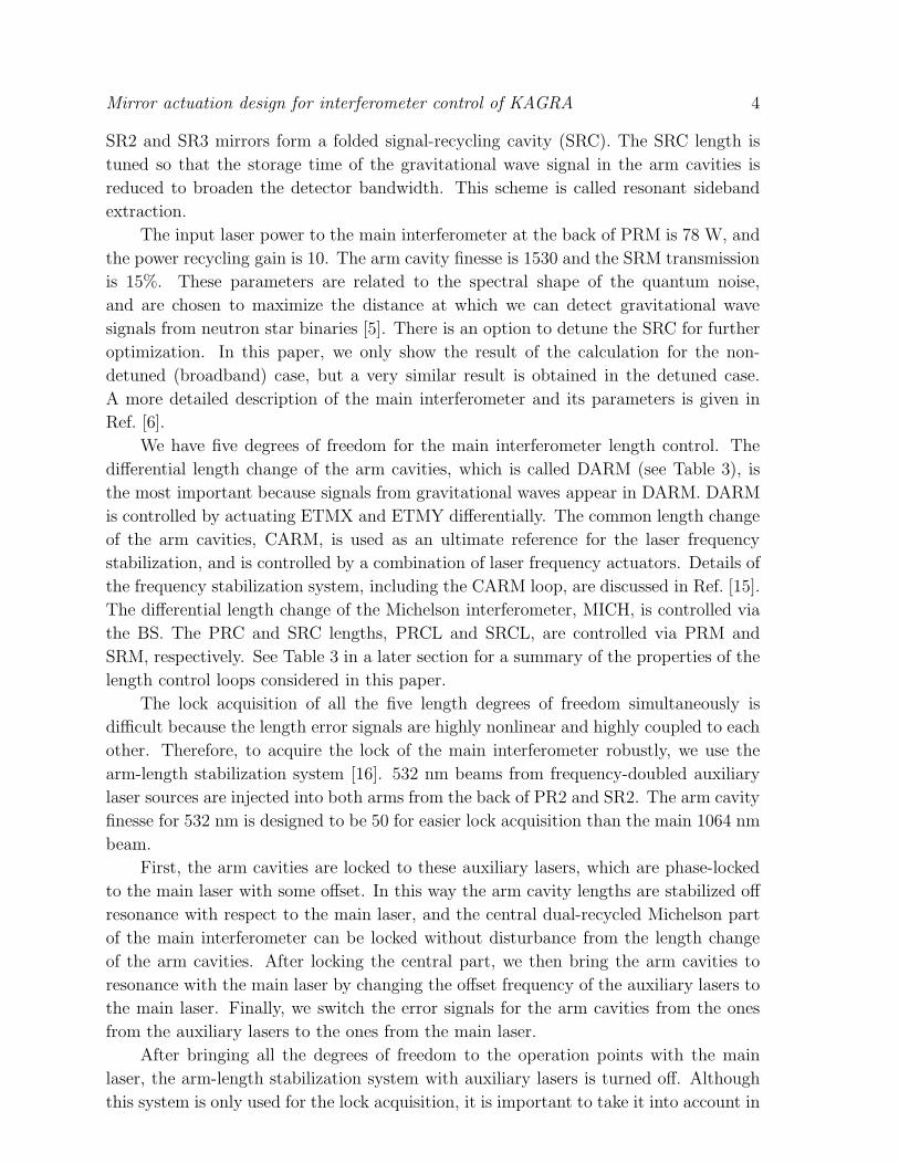
Figure 2. Schematic of the vibration isolation systems. MN: marionette, IM:
intermediate mass, OP: optic. Black dots represent the location of coil-magnet
actuators. Type-A systems are located inside a vacuum tower and the legs of the
inverted pendulum table is fixed onto the ground of the second floor. The legs of the
inverted pendulum table of the Type-B system are fixed onto the outer frame of the
vacuum chamber. The standard filter of the Type-Bp system are fixed onto the inner
frame of the vacuum chamber. Type-C systems are fixed on the vibration-isolated
table with 3-stage stacks.
the actuator range calculation because length sensing noise with auxiliary laser is worse
than that with the main laser. The auxiliary laser has lower power and thus higher shot
noise, as discussed in Sec. 4.4.
3. Suspension configurations
The mirrors for the KAGRA interferometer are suspended from different types of
vibration isolation systems depending on their displacement noise requirements. Mirrors
with stringent displacement noise requirements are suspended by vibration isolation
systems with multiple stages to attenuate the noise from ground motion. The schematic
of the vibration isolation systems used for KAGRA is shown in Fig. 2. ITMs and ETMs
are suspended by a 14-m long eight-stage pendulum called Type-A [17]. The pendulum
is hung from a pre-isolator which consists of a vertical geometric anti-spring (GAS) top
filter [18] supported by an inverted pendulum table [19]. The Type-A system extends
over two stories and the legs of the inverted pendulum table are fixed onto the second
floor. The inverted pendulum table is also used for adjusting the position and the
alignment of the whole suspension chain. From the top GAS filter, three standard GAS
filters, a bottom GAS filter, platform, marionette (MN), intermediate mass (IM), and
the optic (OP) are suspended in the order as mentioned.

Mirro
ractu
atio
ndesign
forinterfero
meter
contro
lofKAGRA
6Table 1. KAGRA suspension and actuator parameters. The coil-magnet actuation efficiencies for Type-A and Type-C are measured
values. All the other parameters are designed values.
Type Type-A Type-B (BS) Type-B (SR) Type-Bp Type-C
Mirrors ITM/ETM BS SRM/SR2/SR3 PRM/PR2/PR3 MCi/MCo/MCe
Mirror diameter [mm] 220 370 250 250 96
Mirror thickness [mm] 150 80 100 100 30
Mirror mass [kg] 22.8 18.9 10.8 10.8 0.47
IM (MN) mass [kg] 20.5 (22.5) 36.5 15.6 15.6 0.71
Wire length for OP [m] 0.35 0.5 0.5 0.5 0.25
Wire length for IM (MN) [m] 0.26 (0.35) 0.5 0.5 0.5 0.25
OP coil turns 100 600 600 600 41
OP coil resistance [Ω] 0.6 12 12 12 2.5
OP magnet size [mm] φ2× 2t φ2× 3t φ2× 5t φ6× 3t φ1× 5t
OP actuation per coil [N/A] 0.0015 0.014 0.023 0.13 0.0014
# of OP longitudinal coils 4 4 4 4 4
OP coil driver type Low Low Low High High
IM coil turns 600 600 600 600
IM coil resistance [Ω] 2 12 12 12
IM magnet size [mm] φ2× 2t φ10× 10t φ10× 10t φ10× 10t
IM actuation per coil [N/A] 0.016 1.3 1.3 1.3
# of IM longitudinal coils 2 1 1 1
IM coil driver type Modified low Low Low High
MN coil turns 600
MN coil resistance [Ω] 2
MN magnet size [mm] φ5× 13t
MN actuation per coil [N/A] 0.43
# of MN longitudinal coils 2
MN coil driver type Modified low

Mirror actuation design for interferometer control of KAGRA 7
IM IRM
MN
IM
OP
M
RM
IRM
platform
bottom filter
Type-A Type-B and Bp
RMOP
Figure 3. Diagram of the recoil mass chain for the Type-A, Type-B and Bp systems.
MNR: marionette recoil mass, IRM: intermediate recoil mass, RM: recoil mass.
The last four stages of the Type-A system are cooled down to cryogenic
temperatures and are called the cryogenic payload [20]. The sapphire mirror is cooled
down to 20 K and the other parts of the crygenic payload are cooled down to 16 K. The
mirror has a higher temperature than the rest because of the heat absorption from the
laser beam. The heat absorbed in the mirror is extracted via 4 sapphire fibers which
hang the mirror from the IM [21]. From the IM, the heat is transferred through pure
aluminum flexible wires connected to upper stages and then to cryocoolers.
For the room-temperature fused-silica mirrors, simpler systems are used. BS, SRM,
SR2 and SR3 are each suspended by a four-stage pendulum called Type-B [22, 23]. Type-
B systems consist of an inverted pendulum table, a top GAS filter, a standard GAS filter,
a bottom GAS filter, an IM, and an OP. PRM, PR2 and PR3 are each suspended from a
triple pendulum called Type-Bp, which is a simplified version of Type-B. Instead of the
inverted pendulum table, the Type-Bp system is supported by a set of motorized linear
stages, called a traverser, for adjusting the position and the alignment of the chain in
the horizontal plane. IMC mirrors are each suspended from a double pendulum fixed
on a three-stage vibration isolation stack [24]. This system is called a Type-C system
and is a modified version of the suspension used for the TAMA300 gravitational wave
detector [25].
Various kinds of actuators are integrated in the suspension systems for position
and alignment controls of the pendulum. The position and alignment controls include
resonant mode damping servos using local displacement sensors integrated in the
suspension systems [22], and global controls using the interferometer error signals. Here,
we focus on the global length control of the interferometer using longitudinal actuators.
There are also vertical and translational actuators, but their effect on the length control
is negligible.
The longitudinal actuators used for the length control consist of coils and magnets,
and actuation is done by controlling the current applied to the coils. The magnets are
glued onto the MN, IM and OP, and coils are fixed on their respective recoil masses
or suspension frames (see Fig. 3). For Type-A suspension, the recoil mass chain is

Mirror actuation design for interferometer control of KAGRA 8
Table 2. Operational amplifiers used for the current source, output resistances at DC
of the coil drivers. The maximum output current applied to a coil from each coil driver
with DAC output of 10 V is also shown. The resistance of the coils is not included
in the output resistance values. The maximum output current of the low power coil
drivers for Type-A OP is 1.3 mA, and that for others are 1.7 mA.
Current source Output resistance Max current to coil
High power OPA548 80 Ω 0.12 A
Low power AD8671 7.8 kΩ 1.7 mA or 1.3 mA
Modified low power AD8671 1.4 kΩ 9.5 mA
suspended from the platform, independently from the main optic chain. For Type-B
and Type-Bp suspensions, the recoil mass for the IM is suspended from the bottom GAS
filter, with the recoil mass for the OP suspended from the IM. Type-C suspensions do
not have actuators on the IM stage, and OP coils are fixed on the suspension frame.
Table 1 summarizes the actuator parameters for each suspension. Mirror sizes and
suspension wire lengths are determined from vibration isolation requirements and other
geometric reasons. Numbers of turns for coils, magnet sizes and coil driver parameters
are determined based on noise and range calculations described in the following sections.
The current applied to the coils is controlled from a digital system. The KAGRA digital
system [26] has 16 bit digital-to-analog converters (DACs) with a range of ±10 V. We
use three types of coil drivers; a high power coil driver, low power coil driver, and
modified version of the low power coil driver. The low power coil driver has a pole at
50 Hz (160 Hz for modified version), and a zero at 310 Hz. It also has a voltage gain of
1.33, except for the one used for the OP stage of the Type-A suspension. Operational
amplifiers used for the current source are different for each driver so that the maximum
output current is defined by the DAC limit, and not the coil driver. The design of each
driver is summarized in Table 2.
The maximum current we can apply to the coil considering the damage to the coil
is more than 500 mA for Type-C, and 100 mA for other suspensions, which is above the
DAC limit. The heat generated by the coils for the Type-A suspension is calculated to
be 2.2 mW at maximum, which is sufficiently small compared with the heat extraction
capability of the cryogenic system [27].
The coil-magnet actuation efficiencies in units of N/A in Table 1 for Type-A
and Type-C are measured values, and those for Type-B and Type-Bp the calculated
values [28]. The actuation efficiencies depend on the position of the magnet relative
to the coil, and the relative position is set to maximize the efficiency within 1 mm.
The positional deviation by 1 mm from the optimal point decreases the efficiency by
approximately 5%. The efficiency could also vary depending on the variation of the
magnetic moment of each magnet, which is measured to be smaller than 20%.
Except for the Type-C suspension, we use samarium-cobalt (SmCo) magnets which
Mirror actuation design for interferometer control of KAGRA 9
whitening
de-whitening
DAC
coil driver coil-magnet
suspension
response
interferometer
response servo filter
feedback signals
DAC noise quantum noise
mirror displacement
magnetic noise coil driver noise
ADC
seismic noise
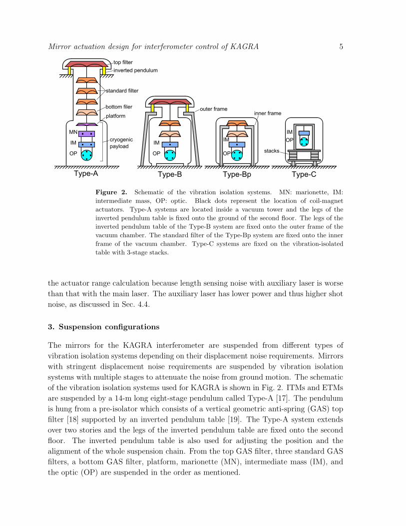
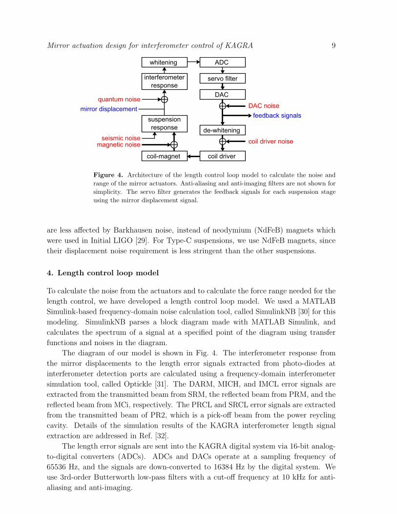
Figure 4. Architecture of the length control loop model to calculate the noise and
range of the mirror actuators. Anti-aliasing and anti-imaging filters are not shown for
simplicity. The servo filter generates the feedback signals for each suspension stage
using the mirror displacement signal.
are less affected by Barkhausen noise, instead of neodymium (NdFeB) magnets which
were used in Initial LIGO [29]. For Type-C suspensions, we use NdFeB magnets, since
their displacement noise requirement is less stringent than the other suspensions.
4. Length control loop model
To calculate the noise from the actuators and to calculate the force range needed for the
length control, we have developed a length control loop model. We used a MATLAB
Simulink-based frequency-domain noise calculation tool, called SimulinkNB [30] for this
modeling. SimulinkNB parses a block diagram made with MATLAB Simulink, and
calculates the spectrum of a signal at a specified point of the diagram using transfer
functions and noises in the diagram.
The diagram of our model is shown in Fig. 4. The interferometer response from
the mirror displacements to the length error signals extracted from photo-diodes at
interferometer detection ports are calculated using a frequency-domain interferometer
simulation tool, called Optickle [31]. The DARM, MICH, and IMCL error signals are
extracted from the transmitted beam from SRM, the reflected beam from PRM, and the
reflected beam from MCi, respectively. The PRCL and SRCL error signals are extracted
from the transmitted beam of PR2, which is a pick-off beam from the power reycling
cavity. Details of the simulation results of the KAGRA interferometer length signal
extraction are addressed in Ref. [32].
The length error signals are sent into the KAGRA digital system via 16-bit analog-
to-digital converters (ADCs). ADCs and DACs operate at a sampling frequency of
65536 Hz, and the signals are down-converted to 16384 Hz by the digital system. We
use 3rd-order Butterworth low-pass filters with a cut-off frequency at 10 kHz for anti-
aliasing and anti-imaging.

Mirror actuation design for interferometer control of KAGRA 10
Table 3. Mirrors used for the feedback, and unity-gain frequencies (UGFs) of the
mirror loops, for the length control assumed in the modeling.
Mirror(s) UGF
DARM (differential arm length) ETMs 200 Hz
MICH (Michelson differential length) BS 50 Hz
PRCL (power recycling cavity length) PRM 50 Hz
SRCL (signal recycling cavity length) SRM 50 Hz
IMCL (input mode cleaner length) MCe 50 Hz
The digital system generates the feedback signal for each stage of the suspension
with infinite impulse response servo filters. The feedback signals are then converted into
analog signals by DACs, and sent to coil drivers for each suspension stage. Whitening
filters and de-whitening filters are inserted before ADCs and after DACs respectively
to effectively reduce ADC and DAC noise. Transfer functions from the actuator force
applied to each suspension stage to the displacement of the mirror are calculated using
the suspension rigid-body simulation tool, called SUMCON [33].
For calculating the feedback signal to check the actuator range, we have to design
the open-loop transfer functions of the length control loops. Table 3 summarizes the
unity-gain frequencies of each loop. The unity-gain frequencies are set to 200 Hz for
DARM and 50 Hz for all the other degrees of freedom. The cross-over frequency between
the OP stage loop and the IM stage loop is set to 10 Hz, and that between the IM stage
and the MN stage is set to 5 Hz. The IMCL control system comprises two loops. One
is the MCe position control loop and the other is the frequency actuator loop used to
stabilize the laser frequency. In this paper, we only consider the MCe position control
loop for the sake of simplicity.
The noises included in this model are described in the following subsections. The
contribution from each noise should be below the displacement noise requirement for
each mirror. Displacement noises of Type-A mirrors define the KAGRA sensitivity, and
the requirement is set so that all the technical noises are below the thermal noise and the
quantum noise limit. The Type-B and Type-Bp mirrors also have displacement noise
requirements since there is a non-negligible coupling of auxiliary degrees of freedom to
the DARM signal. IMC mirrors have a displacement noise requirement since the IMC
is used for the laser frequency stabilization, as discussed in Sec. 2.
To derive the displacement noise requirements, we calculated the transfer functions
from displacements of the mirrors and laser frequency fluctuations to the DARM signal
using Optickle. The displacement noise requirements were set so that the effects of the
mirror displacements on the DARM signal are smaller than the DARM noise above
10 Hz, which is the lower end of the observation band. Details of the requirements can
be found in Refs. [6, 34].
It should be noted that the cryocooler vibration coupled via heat links is not

Mirror actuation design for interferometer control of KAGRA 11
10-2 10-1 100 101
frequency [Hz]
10-11
10-10
10-9
10-8
10-7
10-6
10-5
seism
ic v
ibra
tion [m
/√ Hz]
high-noise model (90% percentile)medium-noise modellow-noise model (10% percentile)
Figure 5. Ground seismic vibration models in the Kamioka mine based on a 1.5-year
long measurement. The high-noise model spectrum was used in our model.
included in our model. The heat links are made of high-purity thin aluminum wires
and they are soft enough that they do not significantly change the mechanical response
of the suspension. The wiring of the heat links are designed so that the vibration from
the cryocoolers does not affect the KAGRA sensitivity [35]. The effect from the heat
links are not significant for the actuation design compared with the noises described
below [23].
4.1. Seismic noise
The motion of the mirror without any feedback is mostly determined by the seismic
vibration of the ground. To estimate the seismic noise of the mirrors, we used the
simulated vibration isolation ratio using SUMCON and the measured spectrum of the
seismic vibration in the Kamioka mine.
The ground seismic vibration data used in our simulation was taken between
September 2009 and February 2011 with a Guralp CMG-3T seismometer. Using
this 1.5-year long data, we have created low-noise, medium-noise and high-noise
models of the Kamioka mine from 10% percentile, median and 90% percentile spectra,
respectively [36]. Figure 5 shows the models of the seismic vibration in the Kamioka
mine. Since the measured data was limited by the sensor noise above 1.5 Hz, we assumed
1/f 2 spectra above that frequency [37]. The seismic vibration varies by roughly an order
of magnitude depending on the weather, wind speed, human activities, etc. The peak
at around 0.2 Hz comes from ocean waves, and is called the microseismic peak. To be

Mirror actuation design for interferometer control of KAGRA 12
conservative, we used the high-noise model spectrum for our simulation.
Our simulation focuses on the longitudinal degrees of freedom of mirrors. However,
vertical vibration of a mirror also couples into the interferometer length signal due to
unintentional asymmetry of the suspension system and slight tilt of the laser beam
axis. The KAGRA tunnel and the laser beam axis are intentionally tilted by 1/300 to
naturally drain water inside the mine [9]. This vertical to longitudinal coupling is critical
since the vibration isolation ratio for the vertical motion is lower. In our simulation, we
assumed 1% for this coupling factor.
4.2. Magnetic noise
The actuation efficiency of a mirror is determined by the gain and the output resistance
of the coil driver, the number of coil turns, and the magnetic moment of the magnet.
The size of the magnet is related to the magnetic noise coupling and thus it must
be sufficiently small to minimize the coupling. As depicted in Fig. 2, every KAGRA
suspension, except for the BS, has four magnets attached to the back surface of the
mirror. The BS has four magnets attached to the front surface instead to ensure that
the magnets do not interfere with the beam. At BS, the beam is centered on the front
surface but not on the back surface. The polarizations of four magnets are alternated to
cancel the net magnetic moment. However, there is a residual magnetic moment since
the magnetic moment of the magnets are not perfectly equal. The residual magnetic
moment couples with environmental magnetic field gradient fluctuation and this creates
magnetic force noise acting on the mirror. This force noise can be estimated with
F1 = 2δµmag∂lB, (1)
where δµmag is the variation of the magnetic moment and ∂lB is the environmental
magnetic field gradient in the longitudinal direction.
From measurements, δµmag is estimated to be smaller than 20% of the nominal
magnetic moment. For ∂lB, we used the estimated gradient from the typical magnetic
field fluctuation measured inside the Kamioka mine with a magnetometer Phoenix
Geophysics AMTC-30 [38]. Assuming the typical length scale for the magnetic
field fluctuation to be 1 m as an pessimistic case [39], ∂lB is estimated to be
4× 10⁻¹² T/m/√Hz at 10 Hz.
The environmental magnetic field gradient difference in the positions of four
magnets also generates magnetic force noise. This can be estimated with
F2 = 2µmagδ(∂lB), (2)
where µmag is the magnetic moment of a magnet and δ(∂lB) is the magnetic field gradient
difference. Measurements show that δ(∂lB) is roughly 10% of the nominal magnetic field
gradient [39].
There are other coupling mechanisms for the magnetic noise, but they are found to
be negligible. The environmental magnetic field induces torque on the magnets, which
leads to rotational motion of the mirror if the torques acting on four magnets do not
Mirror actuation design for interferometer control of KAGRA 13
perfectly cancel each other. This noise couples into the interferometer length signal
when the beam spot is not perfectly centered on the mirror [40]. Assuming a worst case
in which the beam mis-centering is 1 mm [6] and magnetic field difference between four
magnets to be 10%, this effect is estimated to be roughly an order of magnitude smaller
than the effect from F1 and F2. The environmental magnetic field gradient also creates a
lateral force acting on the magnets, which creates a torque on the mirror if forces acting
on four magnets do not perfectly cancel each other. This effect is estimated to be two
orders of magnitude smaller. Magnetization of the mirror itself also couples with the
environmental magnetic field, but this force noise is estimated to be more than three
orders of magnitude smaller. Therefore, we only included the force noise from F1 and
F2 in our model.
Similar calculations were also done for the IM and MN stages. Since the force noises
from the upper stages are attenuated by the suspension, IM and MN stages can have
larger magnets than the OP stage, which gives larger actuation range at low frequencies
below ∼ 10 Hz. For Type-B and Type-Bp suspensions, of the six actuation magnets
on the IM, only one is for longitudinal actuation. An extra magnet with opposite
polarization is inserted inside a magnet holder, called a flag, to cancel the magnetic
moment [28].
4.3. Electronics noise
We can split the noises from various electronics into two categories, sensor electronics
noises and actuator electronics noises. Sensor electronics noises are noises which come
from the displacement sensing of the mirror, such as ADC noise, whitening filter noise,
and dark current of the photo-diodes, and are not included in our model. Electronics
for the sensing are designed so that their noises are smaller than the quantum noise
described in the next subsection, and therefore, can be neglected from the calculation.
The effect of the photo-diode noise is discussed in Ref. [32].
Here, we focus on the actuator electronics noises which couple into the loop after
the servo filter. Noises of the actuation system creates force noise by fluctuation of the
current applied to the coils. Contribution from these noises to the mirror displacement
noise depends solely on the actuation design, and is independent of the servo filter
design.
We included the calculated coil driver noise and the measured DAC noise in our
simulation. The coil driver noise is calculated from operational amplifier noises and
Johnson noise of resisters. The input-equivalent noises are 8 × 10⁻⁹ V/√Hz and
2× 10⁻⁸ V/√Hz at 10 Hz for high power and low power coil driver, respectively.
The DAC noise is measured to be 2 × 10⁻⁶ V/√Hz at 10 Hz and is the largest
actuator electronics noise. To effectively reduce the DAC noise, we use switchable three-
stage whitening filters and dewhitening filters, except for in the IMC suspensions. Each
stage of the whitening filter has a zero at 1 Hz and a pole at 10 Hz, and vice versa for
the dewhitening filters. In our simulation, all three stages are turned on, which means

Mirror actuation design for interferometer control of KAGRA 14
that the DAC noise is effectively reduced by three orders of magnitude above 10 Hz.
Noise from the anti-aliasing and anti-imaging filters are measured to be 4×10⁻⁸ V/√Hz
at 10 Hz, and are negligible compared with the DAC noise.
4.4. Quantum noise
The displacement sensing of a mirror with an interferometer is ultimately limited by
quantum noise. The quantum fluctuation of the laser power creates force noise on the
mirror and this results in quantum radiation pressure noise. The quantum fluctuation
of the laser power on the photo-diode creates shot noise. The shot noise dominates the
sensing noise at high frequency, and this creates excess force noise via the control loop.
Since the actuation efficiency is limited at high frequency, the shot noise contribution is
an important factor for the actuation range. In our simulation, we again used Optickle
to calculate the quantum noise for each length degree of freedom.
As for the DARM loop, we ran the simulation with the quantum noise from the
main 1064 nm laser and also with the quantum noise from the arm-length stabilization
system to check for the range of the actuator. The shot noise of the length sensing of
the arm cavity with auxiliary 532 nm laser is worse than that for the main laser because
the input power and the finesse are less. The input laser power at 532 nm to the arm
cavities is assumed to be 100 mW in our model.
5. Results
The simulated displacement noise spectra of the mirrors using our model are shown in
Fig. 6. The displacement noise requirement plotted in the figure has a safety factor of 10
to ensure that technical noises other than the quantum noise are sufficiently small. The
seismic noise is smaller than the requirement, confirming that the KAGRA vibration
isolation systems sufficiently suppress the ground vibration. The magnetic noise and
the electronics noise are also sufficiently small. The peaks at 30 Hz and 60 Hz in the
magnetic noise spectra are from AC power lines. For every suspension except for IMC,
the electronics noise above ∼ 5 Hz is dominated by the coil driver noise from the OP
stage. For IMC, electronics noise is dominated by DAC noise, since no whitening and
dewhitening filters are applied.
The quantum noise for the Type-A suspension is 10 times larger than the
requirement with a safety factor of 10. This is because the requirement is set from the
DARM displacement sensitivity, which defines the KAGRA sensitivity to gravitational
waves, and the quantum noise limits the sensitivity above ∼ 40 Hz. The DARM
quantum noise in the arm-length stabilization system is also plotted to show that the
shot noise is more than two orders of magnitude larger than that for the main laser.
The quantum noise for Type-B suspensions, however, has to be mitigated. We
will cancel the effect of this on the DARM signal with a feed-forward technique [6, 32].
Using transfer functions from the actuation of the auxiliary degrees of freedom to the

Mirror actuation design for interferometer control of KAGRA 15
100 101 102 103
frequency [Hz]
10-2310-2210-2110-2010-1910-1810-1710-1610-1510-1410-1310-1210-1110-10
dis
pla
cem
en
t [m
/√ Hz
]RequirementSeismicMagneticElectronicsQuantumQuantum (ALS)
(a) Type-A (ETM)
100 101 102 103
frequency [Hz]
10-2310-2210-2110-2010-1910-1810-1710-1610-1510-1410-1310-1210-1110-10
displacement [m
/√ Hz]
RequirementSeismicMagneticElectronicsQuantum
(b) Type-B (BS)
100 101 102 103
frequency [Hz]
10-2310-2210-2110-2010-1910-1810-1710-1610-1510-1410-1310-1210-1110-10
displacement [m
/√ Hz]
RequirementSeismicMagneticElectronicsQuantum
(d) Type-Bp (PRM)
100 101 102 103
frequency [Hz]
10-2310-2210-2110-2010-1910-1810-1710-1610-1510-1410-1310-1210-1110-10
displacement [m
/√ Hz]
RequirementSeismicMagneticElectronicsQuantum
(c) Type-B (SRM)
100 101 102 103
frequency [Hz]
10-2310-2210-2110-2010-1910-1810-1710-1610-1510-1410-1310-1210-1110-10
displacement [m
/√ Hz]
RequirementSeismicMagneticElectronicsQuantum
(e) Type-C (MCe)
Figure 6. Simulated displacement noise spectra of the mirrors. The thick black
lines show the displacement noise requirement with a safety factor of 10. For Type-A,
quantum noise in the arm-length stabilization (ALS) system is also plotted.
DARM signal, we can cancel the effect from the excess mirror displacement caused by
the auxiliary length control loops. Our calculation show that a feed-forward gain of
100 is sufficient to mitigate this quantum noise coupling. The feed-forward gain of 100
corresponds to a transfer function estimation accuracy of 1%, and this is technically
feasible.
The spectra of simulated feedback signals for each suspension stage are shown in
Fig. 7. The root-mean-squares (RMSs) of the feedback signals are 2 V at maximum
and do not exceed the DAC range of 10 V, which means that the actuator strengths

Mirror actuation design for interferometer control of KAGRA 16
10-1 100 101 102 103
frequency [Hz]
10-910-810-710-610-510-410-310-210-1100101102
voltage [V/√ H
z, VRMS]
OPIMMN
(a) Type-A (ETM)
10-1 100 101 102 103
frequency [Hz]
10-910-810-710-610-510-410-310-210-1100101102
voltage [V/√ H
z, VRMS]
OPIM
(b) Type-B (BS)
10-1 100 101 102 103
frequency [Hz]
10-910-810-710-610-510-410-310-210-1100101102
voltage [V/√ H
z, VRMS]
OPIM
(d) Type-Bp (PRM)
10-1 100 101 102 103
frequency [Hz]
10-910-810-710-610-510-410-310-210-1100101102
voltage [V/√ H
z, VRMS]
OPIMMN
(a’) Type-A (ETM) with ALS
10-1 100 101 102 103
frequency [Hz]
10-910-810-710-610-510-410-310-210-1100101102
voltage [V/√ H
z, VRMS]
OPIM
(c) Type-B (SRM)
10-1 100 101 102 103
frequency [Hz]
10-910-810-710-610-510-410-310-210-1100101102
voltage [V/√ H
z, VRMS]
OP
(e) Type-C (MCe)
Figure 7. Spectra of simulated feedback signals for suspension stages. Cumulative
RMS is plotted with dotted lines in units of volts. It is required that the RMS does not
exceed the DAC range of 10 V. For Type-A, spectra when the arm-length stabilization
system is used are also plotted in (a’).

Mirror actuation design for interferometer control of KAGRA 17
Table 4. Summary of KAGRA mirror actuation design. Maximum force actuator can
produce with DAC output of 10 V and actuation efficiency at DC, and sum of actuator
electronics and magnetic noises at 10 Hz for each suspension at each stage are shown.
Max force [N] Efficiency [m/V] Noise [m/√Hz]
Type-A OP 7.7× 10⁻⁶ 1.8× 10⁻⁹ 1.0× 10⁻¹⁹
IM 1.5× 10⁻⁴ 1.7× 10⁻⁸ 4.4× 10⁻²⁰
MN 8.2× 10⁻³ 3.9× 10⁻⁷ 3.6× 10⁻²⁰
Type-B (BS) OP 9.4× 10⁻⁵ 2.6× 10⁻⁸ 1.5× 10⁻¹⁸
IM 2.1× 10⁻³ 1.6× 10⁻⁷ 1.7× 10⁻¹⁹
Type-B (SR) OP 1.5× 10⁻⁴ 7.3× 10⁻⁸ 4.4× 10⁻¹⁸
IM 2.1× 10⁻³ 4.2× 10⁻⁷ 4.2× 10⁻¹⁹
Type-Bp OP 5.7× 10⁻² 2.7× 10⁻⁵ 6.2× 10⁻¹⁶
IM 1.4× 10⁻¹ 2.6× 10⁻⁵ 1.0× 10⁻¹⁷
Type-C OP 7.1× 10⁻⁴ 4.3× 10⁻⁶ 3.6× 10⁻¹⁴
are sufficiently large. For every suspension except for the IMC, the lower frequency
part of the feedback signal is dominated by seismic noise, and the higher frequency part
is dominated by quantum noise. For IMC, the higher frequency part is dominated by
electronics noise.
For the Type-A suspension, the spectrum when the arm-length stabilization system
is used is also plotted in Fig. 7 (a’). The quantum noise at higher frequency is large
and uses up most of the actuation range for the OP and IM stages, but nonetheless, the
RMS does not exceed the DAC range.
The calculated actuator force range and actuator noise for each suspension at each
stage are summarized in Table 4.
6. Actuation range for lock acquisition
Our calculation is done in the frequency-domain, and our model is based on the
static response of the interferometer. Feedback signals when acquiring the lock of the
interferometer should also be calculated to check the force range of actuators.
The force we need to stop the mirror can be roughly estimated from the relationship
between the mirror momentum and the impulse,
F =mv
∆t, (3)
where m and v are the mass and the velocity of the mirror, respectively. ∆t is the time
it takes to pass the linewidth d of the cavity. Since ∆t = d/v, the velocity requirement
for the mirror can be calculated as
vreq =
√
Fmaxd
m. (4)

Mirror actuation design for interferometer control of KAGRA 18
For a Michelson interferometer, d can be estimated with half of the laser wavelength.
Assuming all the feedback is done at the OP stage during lock acquisition, we can
set Fmax to be the maximum force the OP actuator can produce (see Table 4). Calculated
velocity requirements for BS, SRM, PRM, and MCe are 1.6 µm/sec, 0.44 µm/sec,
7.3 µm/sec, and 1.2 µm/sec, respectively. Suspension modeling using SUMCON shows
that these requirements can be fulfilled at the medium-noise seismic level (see Fig. 5),
with sufficient damping servo [23].
For the Type-A suspension, lock acquisition is done with the laser frequency
actuator of the arm-length stabilization system, with the feedback point then gradually
changed from the frequency actuator to the mirror actuator. Therefore, the discussion
above cannot be applied. As for the frequency actuator, we use an acousto-optic
modulator which have been confirmed to have enough range. Details of the arm-length
stabilization system and the laser frequency stabilization system are beyond the scope
of this paper and will be discussed elsewhere.
7. Conclusions
We have developed a frequency-domain model, which incorporates various noises
and realistic suspension responses, to simulate the length control of the KAGRA
interferometer using mirror actuators. With our model, we have determined the mirror
actuation parameters which give sufficient range to control all the interferometer length
degrees of freedom, while keeping the displacement noise from the actuation sufficiently
small. We have also checked that the actuators have sufficient range for acquiring the
lock of the interferometer.
Minimizing the effect of controls noise is important for realizing the target
sensitivity at the lower end of the detector bandwidth. Our model can also be used
to design the mirror actuators of future interferometric gravitational wave telescopes.
Acknowledgments
We would like to thank Ettore Majorana, Jeffrey Kissel, Christopher Wipf and Stefan
Ballmer for fruitful discussions. We appreciate the technical support from the Advanced
Technology Center (ATC) of NAOJ. T. S., Y. E., K. K. and H. T. acknowledges
financial support received from the Advanced Leading Graduate Course for Photon
Science (ALPS) program at the University of Tokyo. C. P. O. acknowledges financial
support received from the Global Science Graduate Course (GSGC) at the University
of Tokyo.
The KAGRA project is supported by MEXT, JSPS Leading-edge Research
Infrastructure Program, JSPS Grant-in-Aid for Specially Promoted Research 26000005,
MEXT Grant-in-Aid for Scientific Research on Innovative Areas 24103005, JSPS Core-
to-Core Program, A. Advanced Research Networks, the joint research program of the
Institute for Cosmic Ray Research, University of Tokyo, National Research Foundation

Mirror actuation design for interferometer control of KAGRA 19
(NRF) and Computing Infrastructure Project of KISTI-GSDC in Korea, the LIGO
project, and the Virgo project.
References
[1] Abbott B P et al (LIGO Scientific Collaboration and Virgo Collaboration) 2016 Phys. Rev. Lett.
116(6) 061102 URL http://link.aps.org/doi/10.1103/PhysRevLett.116.061102
[2] Abbott B P et al (LIGO Scientific Collaboration and Virgo Collaboration) 2016 Living Reviews
in Relativity 19 1 URL http://dx.doi.org/10.1007/lrr-2016-1
[3] Schutz B F 2011 Classical and Quantum Gravity 28 125023 URL
http://stacks.iop.org/0264-9381/28/i=12/a=125023
[4] Acernese F et al (Virgo Collaboration) 2015 Classical and Quantum Gravity 32 024001 URL
http://stacks.iop.org/0264-9381/32/i=2/a=024001
[5] Somiya K (KAGRA Collaboration) 2012 Classical and Quantum Gravity 29 124007 URL
http://stacks.iop.org/0264-9381/29/i=12/a=124007
[6] Aso Y, Michimura Y, Somiya K, Ando M, Miyakawa O, Sekiguchi T, Tatsumi D and
Yamamoto H (The KAGRA Collaboration) 2013 Phys. Rev. D 88(4) 043007 URL
http://link.aps.org/doi/10.1103/PhysRevD.88.043007
[7] Akutsu T (KAGRA Collaboration) 2015 Journal of Physics: Conference Series 610 012016 URL
http://stacks.iop.org/1742-6596/610/i=1/a=012016
[8] Unnikrishnan C S 2013 International Journal of Modern Physics D 22 1341010 URL
http://www.worldscientific.com/doi/abs/10.1142/S0218271813410101
[9] Uchiyama T, Furuta K, Ohashi M, Miyoki S, Miyakawa O and Saito Y 2014 Classical and Quantum
Gravity 31 224005 URL http://stacks.iop.org/0264-9381/31/i=22/a=224005
[10] Hirose E, Bajuk D, Billingsley G, Kajita T, Kestner B, Mio N, Ohashi M, Re-
ichman B, Yamamoto H and Zhang L 2014 Phys. Rev. D 89(6) 062003 URL
https://link.aps.org/doi/10.1103/PhysRevD.89.062003
[11] Hirose E, Craig K, Ishitsuka H, Martin I W, Mio N, Moriwaki S, Murray P G, Ohashi M, Rowan S,
Sakakibara Y, Suzuki T, Waseda K, Watanabe K and Yamamoto K 2014 Phys. Rev. D 90(10)
102004 URL https://link.aps.org/doi/10.1103/PhysRevD.90.102004
[12] KAGRA Collaboration, in preparation
[13] Mizuno J, Strain K, Nelson P, Chen J, Schilling R, Rudiger A, Win-
kler W and Danzmann K 1993 Physics Letters A 175 273 URL
http://www.sciencedirect.com/science/article/pii/037596019390620F
[14] Kwee P, Bogan C, Danzmann K, Frede M, Kim H, King P, Pold J, Puncken O, Savage R L,
Seifert F, Wessels P, Winkelmann L and Willke B 2012 Opt. Express 20 10617–10634 URL
http://www.opticsexpress.org/abstract.cfm?URI=oe-20-10-10617
[15] Michimura Y 2015 KAGRA Frequency Stabilization Servo Modeling Report, jgw-t1503330; avail-
able from https://gwdoc.icrr.u-tokyo.ac.jp/cgi-bin/DocDB/ShowDocument?docid=3330
[16] Staley A, Martynov D, Abbott R, Adhikari R X, Arai K, Ballmer S, Barsotti L, Brooks A F,
DeRosa R T, Dwyer S, Effler A, Evans M, Fritschel P, Frolov V V, Gray C, Guido C J, Gustafson
R, Heintze M, Hoak D, Izumi K, Kawabe K, King E J, Kissel J S, Kokeyama K, Landry M,
McClelland D E, Miller J, Mullavey A, O’Reilly B, Rollins J G, Sanders J R, Schofield RM S, Sigg
D, Slagmolen B J J, Smith-Lefebvre N D, Vajente G, Ward R L and Wipf C 2014 Classical and
Quantum Gravity 31 245010 URL http://stacks.iop.org/0264-9381/31/i=24/a=245010
[17] Hirose E, Sekiguchi T, Kumar R, Takahashi R and for the KAGRA collaboration 2014 Classical and
Quantum Gravity 31 224004 URL http://stacks.iop.org/0264-9381/31/i=22/a=224004
[18] Cella G, DeSalvo R, Sannibale V, Tariq H, Viboud N and Takamori A 2002 Nuclear
Instruments and Methods in Physics Research Section A 487 652 – 660 ISSN 0168-9002 URL
http://www.sciencedirect.com/science/article/pii/S0168900201021933
[19] Takamori A, Raffai P, Marka S, DeSalvo R, Sannibale V, Tariq H, Bertolini A, Cella

Mirror actuation design for interferometer control of KAGRA 20
G, Viboud N, Numata K, Takahashi R and Fukushima M 2007 Nuclear Instruments
and Methods in Physics Research Section A 582 683 – 692 ISSN 0168-9002 URL
http://www.sciencedirect.com/science/article/pii/S0168900207018554
[20] Kumar R, Chen D, Hagiwara A, Kajita T, Miyamoto T, Suzuki T, Sakakibara Y, Tanaka H,
Yamamoto K and Tomaru T 2016 Journal of Physics: Conference Series 716 012017 URL
http://stacks.iop.org/1742-6596/716/i=1/a=012017
[21] Khalaidovski A, Hofmann G, Chen D, Komma J, Schwarz C, Tokoku C, Kimura N, Suzuki T,
Scheie A O, Majorana E, Nawrodt R and Yamamoto K 2014 Classical and Quantum Gravity
31 105004 URL http://stacks.iop.org/0264-9381/31/i=10/a=105004
[22] Pena Arellano F E, Sekiguchi T, Fujii Y, Takahashi R, Barton M, Hirata N, Shoda A, van
Heijningen J, Flaminio R, DeSalvo R, Okutumi K, Akutsu T, Aso Y, Ishizaki H, Ohishi N,
Yamamoto K, Uchiyama T, Miyakawa O, Kamiizumi M, Takamori A, Majorana E, Agatsuma
K, Hennes E, van den Brand J and Bertolini A 2016 Rev. Sci. Instrum. 87 034501 URL
http://aip.scitation.org/doi/abs/10.1063/1.4942909
[23] Sekiguchi T 2016 A Study of Low Frequency Vibration Isolation System for Large
Scale Gravitational Wave Detectors, Ph.D. Thesis, University of Tokyo; available from
https://gwdoc.icrr.u-tokyo.ac.jp/cgi-bin/DocDB/ShowDocument?docid=4155
[24] Takahashi R, Kuwahara F, Majorana E, Barton M A, Uchiyama T, Kuroda K, Araya A, Arai
K, Takamori A, Ando M, Tsubono K, Fukushima M and Saito Y 2002 Review of Scientific
Instruments 73 2428–2433 URL http://dx.doi.org/10.1063/1.1473225
[25] Takahashi R and Arai K (the TAMA collaboration) 2002 Classical and Quantum Gravity 19 1599
URL http://stacks.iop.org/0264-9381/19/i=7/a=350
[26] Miyakawa O (KAGRA Collaboration) 2013 Proceedings of ICALEPCS2013 23 URL
http://epaper.kek.jp/ICALEPCS2013/papers/mocoaab07.pdf
[27] Sakakibara Y, Akutsu T, Chen D, Khalaidovski A, Kimura N, Koike S, Kume T, Kuroda K,
Suzuki T, Tokoku C and Yamamoto K 2014 Classical and Quantum Gravity 31 224003 URL
http://stacks.iop.org/0264-9381/31/i=22/a=224003
[28] Barton M 2015 OSEM Coil/Magnet/Flag Calculation, jgw-t1503239; available from
https://gwdoc.icrr.u-tokyo.ac.jp/cgi-bin/DocDB/ShowDocument?docid=3239
[29] Aasi J et al 2015 Classical and Quantum Gravity 32 115012 URL
http://stacks.iop.org/0264-9381/32/i=11/a=115012
[30] SimulinkNB available from https://github.com/cwipf/SimulinkNb
[31] Optickle available from https://github.com/Optickle/Optickle
[32] Aso Y, Somiya K and Miyakawa O 2012 Classical and Quantum Gravity 29 124008 URL
http://stacks.iop.org/0264-9381/29/i=12/a=124008
[33] SUMCON available from https://gwdoc.icrr.u-tokyo.ac.jp/cgi-bin/DocDB/ShowDocument?docid=3729
[34] Aso Y, Michimura Y and Somiya K 2011 KAGRA Main In-
terferometer Design Document, jgw-t1200913; available from
https://gwdoc.icrr.u-tokyo.ac.jp/cgi-bin/DocDB/ShowDocument?docid=913
[35] Chen D, Naticchioni L, Khalaidovski A, Yamamoto K, Majorana E, Sakakibara Y, Tokoku C,
Suzuki T, Kimura N, Koike S, Uchiyama T and Kawamura S 2014 Classical and Quantum
Gravity 31 224001 URL http://stacks.iop.org/0264-9381/31/i=22/a=224001
[36] Sekiguchi T 2014 Seismic Spectrum in Kamioka Mine, jgw-t1402971; available from
https://gwdoc.icrr.u-tokyo.ac.jp/cgi-bin/DocDB/ShowDocument?docid=2971
[37] Aki K and Richards P G 2009 Quantitative Seismology 2nd ed (University Science Books)
[38] Atsuta S, Ogawa T, Yamaguchi S, Hayama K, Araya A, Kanda N, Miyakawa O,
Miyoki S, Nishizawa A, Ono K, Saito Y, Somiya K, Uchiyama T, Uyeshima
M and Yano K 2016 Journal of Physics: Conference Series 716 012020 URL
http://stacks.iop.org/1742-6596/716/i=1/a=012020
[39] Conte A, Chincarini A, Farinon S, Fiori I, Gemme G, Majorana E, Neri M, Puppo P,
Rapagnani P, Ruggi P and Swinkels B 2014 Study of the magnetic field gradient in the

Mirror actuation design for interferometer control of KAGRA 21
positions of the mirrors magnets for the Beam Splitter Payload, VIR-0363A-14; available from
https://tds.virgo-gw.eu/ql/?c=10413
[40] Kawamura S and Zucker M E 1994 Appl. Opt. 33 3912–3918 URL
http://ao.osa.org/abstract.cfm?URI=ao-33-18-3912