model driven rule engine using meta programming859439/fulltext01.pdf · study at the ericsson...
TRANSCRIPT
1
K T H R o y a l I n s t i t u t e o f T e c h n o l o g y
Model Driven Rule Engine Using Meta Programming -A Case Study from Ericsson Company MASTER OF SCIENCE THESIS IN SOFTWARE ENGINEERING OF DISTRIBUTED SYSTEMS
Maryam Sepasi
Spring 14

3
Sammanfattning – Det växande önskemålet att använda ny teknik, leder till en ökning av att använda mer komplexa programvarudomäner. Dessutom kan det orsaka ett antal utmaningar, som kan lösas genom att förändra sättet som system är utformade på. Företag har tillämpat instruktioner och standarder inom sina organisationer för att minska problemen och öka samstämmigheten mellan sina program och att återanvända komponenter i olika system. Generiska eller specifika metoder kan användas för att implementera sådana system. Eftersom en specifik metod ger en bättre lösning med större fördelar och användbarhet i vissa domäner så följde denna studie denna metod. Denna studie presenterar resultatet av en explorativ fallstudie vid telekombolaget Ericsson där de utmaningar som definierar ett yttre och inre domänspecifikt språk utreddes. Möjligheterna att övergå från en manuellt byggd konfiguration för en radiobasstation till en mer automatiserad och pålitlig systemkonfiguration undersöktes. Dessutom presenteras resultatet av att utveckla ett internt och externt domänspecifikt språk baserade på företagets krav. Fördelar, tillkortakommanden, exempel på domänspecifikt språk och implementationstekniker diskuteras i rapporten. Resultatet av detta examensarbete kommer att användas som en konfigurationsdel som ingår i ett större internt verktyg inom företaget. Detta tillhandahåller en effektiv metod för att hantera komplicerade system på ett enkelt sätt.

4
5
Abstract – The growing request of using new technologies, leads to an increased usage of more complex software domains. In addition, it may cause number of challenges, which can be resolved by changing the way systems are designed. Companies have applied instructions and standards within their organizations to reduce the problems and increase the consistency between their software applications and reusing components in different systems. A generic or specific approach can be used to implement such systems. As a specific approach delivers a better solution with significant advantages and ease of use for particular application domains, this study followed this methodology. This study presents the result of an exploratory case study at the Ericsson telecom company where the challenges of defining an external and internal Domain Specific Language were investigated. The possibilities of how to transfer from a manually built Radio Base Station configuration towards a more automated and reliable system configuration was investigated. Moreover, the results of developing an internal and external DSL based on the company’s requirements are presented. Benefits, shortcomings, example DSLs, and implementation techniques are discussed in this report. The outcome of this thesis work will be used as a configuration part that is included in a larger in-house tool within the company. This provides an effective method to handle complicated system in a simple manner.


7
Acknowledgment
This thesis is funded by the Ericsson company which is gratefully acknowledged. The author would especially like to thank Johan Schönning at the Ericsson company for his valuable contribution to this research, Fredrik Kilander at KTH for his thoughtful guiding of this thesis, and to all colleagues at the Ericsson company for their support during this work.

9
Table of Contents
1 Introduction .......................................................................................................... 11
1.1 Problem Description ...................................................................................... 12
1.2 Method Summary .......................................................................................... 12
1.3 Overview ....................................................................................................... 12
2 Background .......................................................................................................... 15
2.1 DSL ............................................................................................................... 15
2.1.1 Internal DSL........................................................................................... 18
2.1.2 External DSL ......................................................................................... 18
2.1.3 External versus Internal DSLs ............................................................... 19
2.1.4 Existing DSLs ........................................................................................ 20
2.2 General-purpose languages versus DSLs ...................................................... 21
2.3 BNF and EBNF ............................................................................................. 23
2.4 DSL and Java agile based.............................................................................. 24
2.5 Model Driven Development .......................................................................... 25
2.6 Different Computational Models .................................................................. 26
2.7 Intentional domain workbench ...................................................................... 27
2.8 Different DSL tools ....................................................................................... 28
2.8.1 Eclipse and Xtext: .................................................................................. 28
2.9 Telecom Network at Ericsson ....................................................................... 28
3 Research Approach .............................................................................................. 31
3.1 Research setting............................................................................................. 31
3.2 Research process ........................................................................................... 32
3.3 Data collection............................................................................................... 33
3.4 Data analysis ................................................................................................. 34
3.5 Limitations and challenges ............................................................................ 34
4 Solutions .............................................................................................................. 35
4.1 Solution 1 - Database ................................................................................... 35
4.2 Solution 2 - External DSL ............................................................................. 38
4.3 Solution 3 – Internal DSL ............................................................................. 42
4.4 Reflections ..................................................................................................... 45
5 Conclusion ........................................................................................................... 47
6 Future work .......................................................................................................... 47
7 References ............................................................................................................ 49

11
1 Introduction The trend of using complex and large systems is growing day by day; managing complex data sets becomes difficult to process and developing such a software in a domain like telecommunication represents one of the most complex construction tasks human undertake (Jennings, 2001). As Jennings (2001) claims, researchers continue to strive for more effective techniques to support and make engineering process easier. Therefore it requires having effective system analysis to improve decision-making in critical development process. Although new technologies and complex systems introduce many new opportunities for organizations, they also present new challenges (Crnkovic, 2001). So the large-scale systems provide foundations for handling multiple critical constraints. Hence it needs the use of practical theories and to have a detail examination of system elements and structure to accommodate the scale.
As Bass et al. (2003) discussed, the focus on the software, which executes a specific purpose, can present some problems later on. For instance, applications are often restructured not because of changing requirements, but because of troubles in maintaining them, updating them, being inflexible to use, not having good performance, and so on. Therefore properly and carefully designed structured systems may cause better advantage over common issues of the software development life cycle. In addition, Curtis et al. (1988) stated that designing a system requires a careful study of problem domain. The system requirements and the stakeholders expectation from the outcome of the system should be specified in detail. Jennings (2001) mentioned that a system may be composed of interrelated subsystems and may be hierarchic in the structure, until the lowest level of elementary subsystem is reached. So some generic forms between subsystems can be recognized that these relationships are not static: they regularly modify over time. In addition, we need to know how well the system will perform and also how will be maintained afterwards. The well-structured system is of course easier to deal with when it comes to changes and upgrades. As mentioned above, as a complex system develops, its execution leans away from the intended design models. This study investigated different solutions for designing a telecommunication system for the Ericsson company. The telecommunication systems are developing rapidly and most of the Telecom companies are aiming to own a full system, rather than just providing the network. So this study considered the Ericsson telecommunication system, which includes interchangeable software components and will be reused in a large scale. Therefore, as Fowler (2010) mentioned, one of the best ways to design a system is to define a Domain Specific Language (DSL). By implementing the DSL, a complex domain model can be managed more efficiently.
Mernik (2005) stated that in order to drive the system development effort smoothly and also define the DSL, a consistent design pattern should be introduced. This also opens the opportunity to remove the dependency on system designers at later stages of the project. DSLs are languages to a specific application domain. They suggest considerable change in expressiveness and ease of use compared with general-purpose programming languages in their domain of application.
According to Fowler (2010), the first step to build a DSL is to carefully clarify the need of using it. Improving development productivity is one of the most important characteristics of using a DSL. In addition, by having a DSL, it is much simpler to
12
read chunk of code, to discover the flaws and even change the system. Fowler (2010) also mentioned the same motivation to use meaningful and relevant variable names, to have documentation and to follow clear coding structure for building DSL tool.
In a telecommunication system a service area is divided into a plurality of cells. Radio Base Stations (RBSs) are arranged related to individual cells of the plurality of cells (Nakata et al. 2000). So a telecommunication system belongs to a complex category of systems. It contains large number of parts that have many interactions. Thus there is a need to provide structure and techniques to handle this complexity. Though in this study, a research has been done to compare different approaches and assess their suitability for the telecommunication domain, which in this case is the Ericsson company. To be able to configure a RBS, the operator needs to supply the configuration data files. Today, the existing possible numbers of configurations is large and growing exponentially. Therefore, creating such files manually is an error prone and time consuming process. It means that employing an automatic system to generate the configuration files using a DSL is very advantageous.
1.1 Problem Description To be able to configure a RBS, the operator needs to supply the configuration data files. Today, the existing possible numbers of configurations is large and growing exponentially. Therefore, creating such files manually is an error prone and time consuming process. It means that employing an automatic system to generate the configuration files is very advantageous. The aim of this research is to find a way to reduce the complexity for creating RBS configuration. To reach this point, the possibility of defining a DSL instead of using a General-purpose Programming Language is investigated in detail. In this case study, the challenges of defining an external and internal DSL based on internal requirements of the Ericsson company was evaluated. The local demands of the company were carefully considered in order to obtain an effective solution.
1.2 Method Summary Detail information about the research approach and methodology is presented in chapter 3. This exploratory case study contributes in the following ways:
1. By investigating the current business requirements in order to assess the challenges of the existing solutions and how to suggest the best solution in order to be compatible with the other systems within the organization.
2. By evaluating the possibility of defining the DSLs for the RBS system components and the future possible updates. This can be achieved by reading existing configuration documents and by interviewing Ericsson staff handling RBS configuration documents.
3. By developing an internal and external DSL for different hardware units, logical units and also define the rules in DSLs. In addition to evaluate each of these DSLs to see which one suits better within the Company requirements.
1.3 Overview This report is structured in the following way: First a general review of the problem together with the main purpose behind this study is presented in this section. Section 2 introduces the literature review about the DSLs and GPLs systems together with
13
challenges of using each of them. Internal and external DSLs are discussed in detail together with their advantages and drawbacks.
In section 3, the research method used in this exploratory case study is introduced. It explains the research setting and research process of this investigation. It also includes some details about the data collection and data analysis step.
In section 4, the solutions will be concluded and the explanation of the obtained results will be presented. The detail steps of the solutions cannot be shared by considering the limitation of distributing the properties of the Ericsson company. However, a fairly complete procedure of the solutions is presented in this section.
Finally sections 5 and 6 include the conclusions of this thesis work together with the possible future studies that can extend the borders of the current investigation and improve its outcome.

15
2 Background This section will present the basic knowledge, which is required for this study and it is constructed throughout reviewing related literature from several resources.
2.1 DSL Domain Specific Language is a beneficial term and conception, but it should be considered that it has no distinct boundaries. Sometimes it is hard to distinguish the DSLs from other things. Although the DSL concept is used for a while, but the same as most other things in software development process, it has a very blurry borderline and never had a very firm explanation. Thus, there are many different definitions of DSLs, but most of them include some common elements such as programing language, limited expressiveness and domain focus. Two popular definitions of the DSLs are as follows:
• “A domain-specific language (DSL) is a programming language or executable specification language that offers, through appropriate notations and abstractions, expressive power focused on, and usually restricted to, a particular problem domain”(Van Deursen and Klint, 2002). They also mentioned that to have a proficiently well-designed DSL, the deep understanding of the fundamental system domain is required.
• Fowler (2010) states that “Domain-specific language (noun): a computer programming language of limited expressiveness focused on a particular domain”. He argued that a DSL is used to instruct a computer to do specific task. Thus, although the DSL structure should be designed to be understandable by humans, but it should still be executable by a computer. In despite of general-purpose languages, it is not possible to build up an entire system in a DSL, to use it for a particular aspect of the system. Therefore, this feature of DSL makes it worthwhile (Fowler, 2010).
Although the explanations are somehow dissimilar, large degree of similarities can also be seen, for example, both of them specify that the behavior and the structure of the DSL be influenced by the domain concept of the system and higher abstractions. Consequently, focusing on the specific problem domain of the system is the most often mentioned and essential characteristic in the definition of the DSLs.
In most cases, DSL program are transformed to call a common set of instructions designed to perform a frequently used operation within a program, such as libraries. Thus the purpose of using the DSL is to conceal the details of those libraries (Voelter et al., 2013). Although many DSLs have been operated and utilized over the years, the efficient study of DSLs has only started more recently. As mentioned before, one of the most required prior condition for making a DSL is a detailed analysis and construction of the application domain. Strategies for obtaining such an understanding are specified by the research area of domain analysis that examines different methods of modeling domains (Van Deursen and Klint, 2002). First of all it is important to differentiate the domain content into execution engine, platform and DSL (see Figure 1).
16
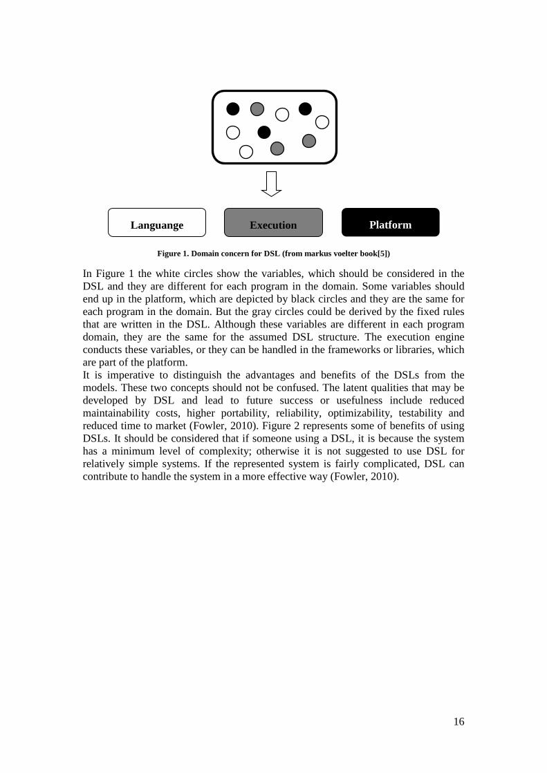
Figure 1. Domain concern for DSL (from markus voelter book[5])
In Figure 1 the white circles show the variables, which should be considered in the DSL and they are different for each program in the domain. Some variables should end up in the platform, which are depicted by black circles and they are the same for each program in the domain. But the gray circles could be derived by the fixed rules that are written in the DSL. Although these variables are different in each program domain, they are the same for the assumed DSL structure. The execution engine conducts these variables, or they can be handled in the frameworks or libraries, which are part of the platform. It is imperative to distinguish the advantages and benefits of the DSLs from the models. These two concepts should not be confused. The latent qualities that may be developed by DSL and lead to future success or usefulness include reduced maintainability costs, higher portability, reliability, optimizability, testability and reduced time to market (Fowler, 2010). Figure 2 represents some of benefits of using DSLs. It should be considered that if someone using a DSL, it is because the system has a minimum level of complexity; otherwise it is not suggested to use DSL for relatively simple systems. If the represented system is fairly complicated, DSL can contribute to handle the system in a more effective way (Fowler, 2010).
Platform Execution
Languange
17
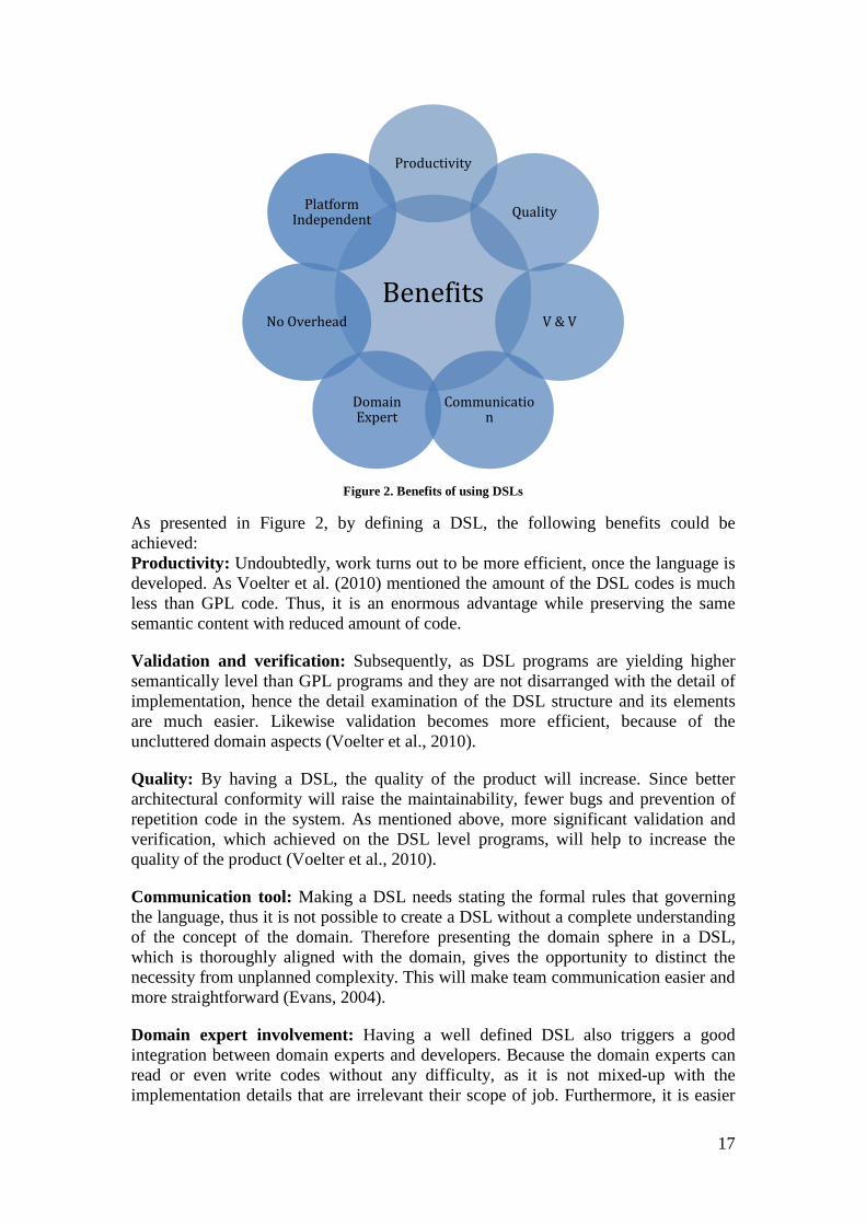
Figure 2. Benefits of using DSLs
As presented in Figure 2, by defining a DSL, the following benefits could be achieved: Productivity: Undoubtedly, work turns out to be more efficient, once the language is developed. As Voelter et al. (2010) mentioned the amount of the DSL codes is much less than GPL code. Thus, it is an enormous advantage while preserving the same semantic content with reduced amount of code.
Validation and verification: Subsequently, as DSL programs are yielding higher semantically level than GPL programs and they are not disarranged with the detail of implementation, hence the detail examination of the DSL structure and its elements are much easier. Likewise validation becomes more efficient, because of the uncluttered domain aspects (Voelter et al., 2010).
Quality: By having a DSL, the quality of the product will increase. Since better architectural conformity will raise the maintainability, fewer bugs and prevention of repetition code in the system. As mentioned above, more significant validation and verification, which achieved on the DSL level programs, will help to increase the quality of the product (Voelter et al., 2010).
Communication tool: Making a DSL needs stating the formal rules that governing the language, thus it is not possible to create a DSL without a complete understanding of the concept of the domain. Therefore presenting the domain sphere in a DSL, which is thoroughly aligned with the domain, gives the opportunity to distinct the necessity from unplanned complexity. This will make team communication easier and more straightforward (Evans, 2004).
Domain expert involvement: Having a well defined DSL also triggers a good integration between domain experts and developers. Because the domain experts can read or even write codes without any difficulty, as it is not mixed-up with the implementation details that are irrelevant their scope of job. Furthermore, it is easier
Benefits
Productivity
Quality
V & V
Communication
Domain Expert
No Overhead
Platform Independent
18
for the domain experts to at least join the developers to write a code or to do further works such as validation and reviews (Voelter et al., 2010).
No overhead: Voelter et al. (2010) also mention that the runtime overhead can be ignored by generating the source code from the DSL program. Because by using a generator similar to compiler, the abstractions can be eliminated and just the efficient code with low overhead will be generated. Thus if the performance, resource efficiency or the amount of data passing through a system or process is a concern, then DSL can be very beneficial solution. Platform Independent/ Isolation: The DSL code is independent of the target platform. Because the DSL itself as an execution parser makes the system not depending on another underlying technology platform. So it should be mentioned that the system portability and maintainability are increased by the DSL, as it supports the division and distinction of the system elements. For instance, application logic is detached from the implementation details and the target platform.
2.1.1 Internal DSL There are two main types of DSLs: internal and external DSLs. The internal DSLs are most approachable form of DSLs, because they are constructed on top of a defined programming language, which can be called the host language (Mernik et al. 2005). Fowler (2010) stated that there is no need to study about the grammar and parsing the language, since with internal DSLs, users deal with the regular language environment. The existing language infrastructure, which contains compiler, editor and interpreter, can be reused (Gunther et al. 2010). Therefore, as Gunther et al. (2010) claims that internal DSLs are built with less effort, there has been a large amount of interest in them over the last few years. According to Fowler (2010), by using the internal DSLs, developers are limited to the host language, because any expressions and syntax is going to be used should follow the host language. As mentioned before, one of the benefits of using internal DSLs is that the written language model can be directly manipulated in terms of objects, attributes and statements while there is no need to be parsed and analyzed for execution. It can be professed that making an internal DSL can be useful for the people who prefer to have syntactically correct declarations from the beginning point, because as mentioned before they stick to the host language syntax.
2.1.2 External DSL Unlike the internal DSLs, the external DSLs deliver a better syntactic independency and also make capable to use any desirable syntax by the developers. External DSLs need considerable process of investigation to obtain better result, as every new techniques and new languages have to be learned too. Thus in order to find a skillful or efficient way of building or achieving well-designed external DSL, considerable investments are required (Gunther et al, 2010). Putting an external DSL into practice is different from internal DSLs, since the process of parsing it is on the pure input text-files, which are not limited by any specific host language (Fowler, 2010). It should be stated that the procedure and methods utilized to parse the texts are basically the same as those that have been utilized in parsing the programing languages. The complete development environments explanation for external DSLs can be found in Bahlke et al. (1986) and Balance (1990), which is out of scope of this study.
19
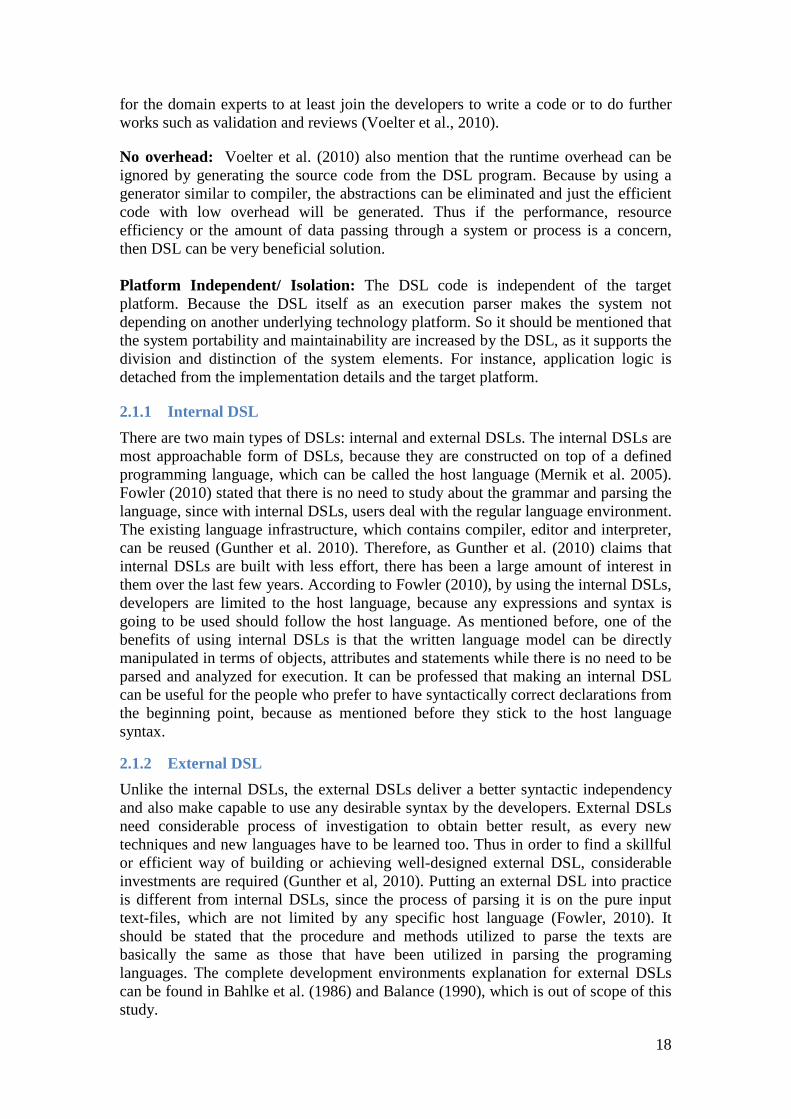
2.1.3 External versus Internal DSLs As mentioned in section 2.1.1 and also discussed by Voelter et al. (2010), the internal DSLs are embedded into GPL and generally the host languages are dynamically typed. Also internal DSLs implementation is based on the meta-programming. As Ghosh (2011) stated “Meta-programming is about writing a program, which write programs”. Typo checks are mostly executed at the runtime, by utilizing the dynamically typing. One of the key advantages of the external DSL is a static type system. Most of the DSLs with dynamic style structures are better suits as internal DSLs, because they rely on the dynamic style structure of the hosts language. These two systems adjust types with the language elements and afterward the types are verified against the defined typing rules. Also as depicted in Figure 3, making the internal DSL is simpler because, as declared before, it is limited to the host language. Accordingly writing an external DSL and defining all the grammar from the scratch is more complicated, but it worth for the flexibility provided.
Figure 3. The difference between two DSL origins
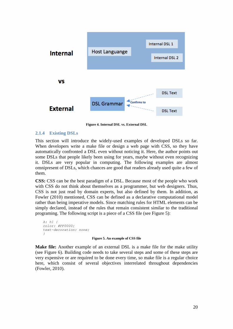
To conclude, the type checks are performed as the system executes in dynamic style structures, while in static style structures, type checks are performed a head of execution and it is based on the type specification in the system. In addition, Figure 4 represents a basic difference between internal and external DSLs.
Internal External
20
Figure 4. Internal DSL vs. External DSL
2.1.4 Existing DSLs This section will introduce the widely-used examples of developed DSLs so far. When developers write a make file or design a web page with CSS, so they have automatically confronted a DSL even without noticing it. Here, the author points out some DSLs that people likely been using for years, maybe without even recognizing it. DSLs are very popular in computing. The following examples are almost omnipresent of DSLs, which chances are good that readers already used quite a few of them.
CSS: CSS can be the best paradigm of a DSL. Because most of the people who work with CSS do not think about themselves as a programmer, but web designers. Thus, CSS is not just read by domain experts, but also defined by them. In addition, as Fowler (2010) mentioned, CSS can be defined as a declarative computational model rather than being imperative models. Since matching rules for HTML elements can be simply declared, instead of the rules that remain consistent similar to the traditional programing. The following script is a piece of a CSS file (see Figure 5):
A: h1 { color: #FF0000; text-decoration: none; }
Figure 5. An example of CSS file
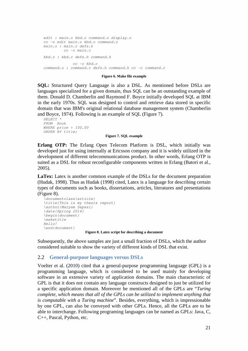
Make file: Another example of an external DSL is a make file for the make utility (see Figure 6). Building code needs to take several steps and some of these steps are very expensive or are required to be done every time, so make file is a regular choice here, which consist of several objectives interrelated throughout dependencies (Fowler, 2010).
21
edit : main.o kbd.o command.o display.o cc -o edit main.o kbd.o command.o main.o : main.c defs.h
cc -c main.c
kbd.o : kbd.c defs.h command.h
cc -c kbd.c command.o : command.c defs.h command.h cc -c command.c
Figure 6. Make file example
SQL: Structured Query Language is also a DSL. As mentioned before DSLs are languages specialized for a given domain, thus SQL can be an outstanding example of them. Donald D. Chamberlin and Raymond F. Boyce initially developed SQL at IBM in the early 1970s. SQL was designed to control and retrieve data stored in specific domain that was IBM's original relational database management system (Chamberlin and Boyce, 1974). Following is an example of SQL (Figure 7).
SELECT * FROM Book WHERE price > 100.00 ORDER BY title;
Figure 7. SQL example
Erlang OTP: The Erlang Open Telecom Platform is DSL, which initially was developed just for using internally at Ericsson company and it is widely utilized in the development of different telecommunications product. In other words, Erlang OTP is suited as a DSL for robust reconfigurable components written in Erlang (Batori et al., 2005).
LaTex: Latex is another common example of the DSLs for the document preparation (Hudak, 1998). Thus as Hudak (1998) cited, Latex is a language for describing certain types of documents such as books, dissertations, articles, literatures and presentations (Figure 8).
\documentclass{article} \title{This is my thesis report} \author{Maryam Sepasi} \date{Spring 2014} \begin{document} \maketitle Hello! \end{document}
Figure 8. Latex script for describing a document
Subsequently, the above samples are just a small fraction of DSLs, which the author considered suitable to show the variety of different kinds of DSL that exist.
2.2 General-purpose languages versus DSLs Voelter et al. (2010) cited that a general-purpose programming language (GPL) is a programming language, which is considered to be used mainly for developing software in an extensive variety of application domains. The main characteristic of GPL is that it does not contain any language constructs designed to just be utilized for a specific application domain. Moreover he mentioned all of the GPLs are “Turing complete, which means that all of the GPLs can be utilized to implement anything that is computable with a Turing machine”. Besides, everything, which is impressionable by one GPL, can also be conveyed with other GPLs. Hence, all the GPLs are to be able to interchange. Following programing languages can be named as GPLs: Java, C, C++, Pascal, Python, etc.
22
As Deursen and Klint (1998) stated, DSLs can be utilized in a more effective and easier way for a specific domain rather than GPLs regarding to maintenance rates and productivity. However, it should be mentioned that GPLs are perfectly well known in the lifetime of the software development process and most of the software engineers are familiar with the characteristics of them. Although it is more problematic to integrate the domain experts in the last phases of the GPL software development process (Gray et al. 2008). Since having a good programming skills is the most significant factor of using GPLs. Thus the domain experts who are not professionals in coding part cannot help on this stage. As mentioned at the section 2.1 and also Grey et al. (2008) stated, domain experts can also concentrate on the programing parts and can even do programing by working with DSLs. It is still most common choice to develop applications by using GPLs rather than DSLs. Although DSLs helpfulness is recognized and accepted, but still require promoting it among the experts. Because as Fowler (2010) specified, DSLs has been around for a long time, but lack of considerable information about how to work with them and also lack of information about how to program with them is a significant impediment.
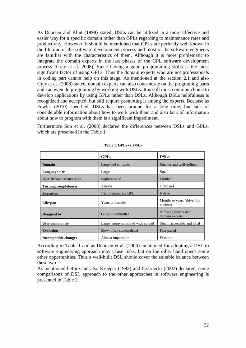
Furthermore Sun et al. (2008) declared the differences between DSLs and GPLs, which are presented in the Table 1.
Table 1. GPLs vs. DSLs
GPLs DSLs
Domain Large and complex Smaller and well-defined
Language size Large Small
User defined abstraction Sophisticated Limited
Turning completeness Always Often not
Execution Via intermediary GPL Native
Lifespan Years to decades Months to years (driven by context)
Designed by Guru or committee A few engineers and domain experts
User community Large, anonymous and wide spread Small, accessible and local
Evolution Slow, often standardized Fast-paced
Incompatible changes Almost impossible Feasible
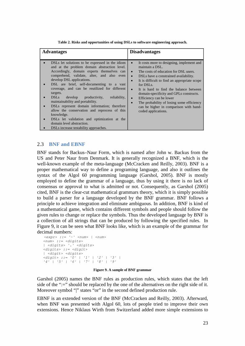
According to Table 1 and as Deursen et al. (2000) mentioned for adopting a DSL to software engineering approach may cause risks, but on the other hand opens some other opportunities. Thus a well-built DSL should cover the suitable balance between these two. As mentioned before and also Krueger (1992) and Czarnecki (2002) declared, some comparisons of DSL approach to the other approaches in software engineering is presented in Table 2.
23
Table 2. Risks and opportunities of using DSLs to software engineering approach.
Advantages Disadvantages
• DSLs let solutions to be expressed in the idiom and at the problem domain abstraction level. Accordingly, domain experts themselves can comprehend, validate, alter, and also even develop DSL applications.
• DSL are brief, self-documenting to a vast coverage, and can be reutilized for different targets.
• DSLs develop productivity, reliability, maintainability and portability.
• DSLs represent domain information; therefore allow the conservation and reprocess of this knowledge.
• DSLs let validation and optimization at the domain level abstraction.
• DSLs increase testability approaches.
• It costs more to designing, implement and maintain a DSL.
• The costs of education for DSL users. • DSLs have a constrained availability. • It is difficult to find an appropriate scope
for DSLs. • It is hard to find the balance between
domain-specificity and GPLs constructs. • Efficiency can be lower • The probability of losing some efficiency
can be higher in comparison with hand-coded applications.
2.3 BNF and EBNF BNF stands for Backus–Naur Form, which is named after John w. Backus from the US and Peter Naur from Denmark. It is generally recognized a BNF, which is the well-known example of the meta-language (McCracken and Reilly, 2003). BNF is a proper mathematical way to define a programing language, and also it outlines the syntax of the Algol 60 programming language (Garshol, 2005). BNF is mostly employed to define the grammar of a language, thus by using it there is no lack of consensus or approval to what is admitted or not. Consequently, as Garshol (2005) cited, BNF is the clear-cut mathematical grammars theory, which it is simply possible to build a parser for a language developed by the BNF grammar. BNF follows a principle to achieve integration and eliminate ambiguous. In addition, BNF is kind of a mathematical game, which contains different symbols and people should follow the given rules to change or replace the symbols. Thus the developed language by BNF is a collection of all strings that can be produced by following the specified rules. In Figure 9, it can be seen what BNF looks like, which is an example of the grammar for decimal numbers: <expr> ::= '-' <num> | <num>
<num> ::= <digits> | <digits> '.' <digits> <digits> ::= <digit> | <digit> <digits> <digit> ::= '0' | '1' | '2' | '3' | '4' | '5' | '6' | '7' | '8' | '9'
Figure 9. A sample of BNF grammar
Garshol (2005) names the BNF rules as production rules, which states that the left side of the “:=” should be replaced by the one of the alternatives on the right side of it. Moreover symbol “|” states “or” in the second defined production rule.
EBNF is an extended version of the BNF (McCracken and Reilly, 2003). Afterward, when BNF was presented with Algol 60, lots of people tried to improve their own extensions. Hence Niklaus Wirth from Switzerland added more simple extensions to
24
BNF that made expressing grammars more useful (Pattis, 1980). The option and repetition control forms are added to EBNF. So, although EBNF seems to be more sophisticated regarding to more features, but it is described in a simpler way to be more understandable. The extensions vary, but mostly are derived from regular expression syntax, such as:
• “*”: means 0 or more occurrences • “+”: means 1 or more occurrences • “?”: means 0 or 1 occurrences (sometimes “[ … ]” used instead)
Following is the same grammar as written above but in EBNF: <expr> := '-'? <digit>+ ('.' <digit>+)? <digit> := '0' | '1' | '2' | '3' | '4' | '5' | '6' | '7' | '8' | '9'
It should be mentioned that further explanation of the symbols and syntax of the BNF and EBNF is beyond the scope of this paper.
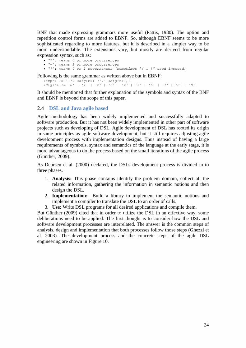
2.4 DSL and Java agile based Agile methodology has been widely implemented and successfully adapted to software production. But it has not been widely implemented in other part of software projects such as developing of DSL. Agile development of DSL has rooted its origin in same principles as agile software development, but it still requires adjusting agile development process with implementation designs. Thus instead of having a large requirements of symbols, syntax and semantics of the language at the early stage, it is more advantageous to do the process based on the small iterations of the agile process (Günther, 2009).
As Deursen et al. (2000) declared, the DSLs development process is divided in to three phases.
1. Analysis: This phase contains identify the problem domain, collect all the related information, gathering the information in semantic notions and then design the DSL.
2. Implementation: Build a library to implement the semantic notions and implement a compiler to translate the DSL to an order of calls.
3. Use: Write DSL programs for all desired applications and compile them. But Günther (2009) cited that in order to utilize the DSL in an effective way, some deliberations need to be applied. The first thought is to consider how the DSL and software development processes are interrelated. The answer is the common steps of analysis, design and implementation that both processes follow those steps (Ghezzi et al. 2003). The development process and the concrete steps of the agile DSL engineering are shown in Figure 10.

25
Figure 10. The Agile DSL development Process, Günther (2009)
As depicted in Figure 10, the development uses steps that are mutual to application development in general. In the domain design phase, the static and the dynamic domain model are designed. The model expresses entities, attributes, relationships, and operations. Then, the language design step builds DSL expressions that represent this domain model. Ultimately, the expressions are employed in the language implementation phase. Several pattern that support common DSL development problems are used in this step (Günther, 2009).
2.5 Model Driven Development One of the major problems in the software industry is the need for developing more complex and software systems in a shorter time and with lower budgets. Thus as Selic (2003) mentioned the desire to use code generation approaches has been grown. Hence for having a better development within organizations, raising the level of abstractions will increase the productivity. In addition, as Selic (2003) cited by achieving the abstraction level of software systems, the system problems and its possible solutions can be more comprehensible.
Modern Driven Development (MDD) outlines a set of standards for transforming models. MDD characteristic is more focus on the model rather than computer programs in software development process. Thus the first advantage that will be obtained of this is that models more bound to the underlying implementation technology and much closer to the problem domain. Furthermore, it also allows the domain experts to produce a system and not just coding experts (Selic, 2003). It should be mentioned that if there is code generation from the models, usually it is not necessary to test them in detail to determine the accuracy of them. As Selic (2003) stated, having “experience with MDD in industrial settings indicates that code
26
efficiency and correctness are not the primary challenges of MDD”. Moreover, modern enhanced compilers can perform better than most experts regarding the code effectiveness.
2.6 Different Computational Models As Fowler (2010) mentioned, GPLs follow the imperative computational models, which is kind of giving a sequence of the peremptory commands and steps that differ based on the conditionals and loops. In addition, object oriented languages grounded in the imperative models. Fowler (2010) also cited, DSLs support something other than imperative approach, which he called it more declarative. As there are different computational approaches to construct DSLs, therefore it can be another convincing reason to use them. Most of the domain experts think about the problems in a non-imperative approach, thus DSLs depiction allows them to comprehend the program in a more clear way.
There are many different computational models available in the literature such as decision tables, production rule systems, state machine, dependency network, etc.
Decision tables: Decision tables deliver a distinctive and more useful way of viewing and managing large sets of symmetric business rules. They are used to model complicated programming logic. They can make it easy to see that all possible combinations of conditions have been considered; when conditions are missed, it is easy to see this. The tables are composed of four parts: conditions, actions, condition alternatives (each column is a rule), and actions for the rules (Vanthienen and Geert, 1994).
Production rule systems: Production rule system represents comprehension in the form of rules. Rule-based systems utilize a working memory that primarily includes the input data for a particular run, and an inference engine to find match rules and execute them. On the other hand, the production rule system provides the notion of a set of rules, where each rule contains a condition and a consequent action. The system executes the rules on the data it has within a sequence of cycles, each cycle detecting the rules whose conditions alike, then applies the rules actions. A Production Rule System is generally at the core of an expert system (Quinlan, 1987).
State machine: A state machine is a model, which is designed by the set of states. It includes the initial state and a trigger to relate the state pairs (Lamport et al, 2010). It models the different ways in which an object acts in response to a particular situation or stimulus. By this model, the object behavior will divide into different states, thus regarding to the state of the object in each moment each event leads to a transition to a different state (Fowler, 2010).
Dependency network: This method delivers a distinct system level analysis for a network. For instance the way in which constituent parts are interrelated or arranged. Thus this approach analyses the fundamental topological relationship between nodes in the network and then delivers a conclusion reached on the basis of nodes activity relations reasoning (Heckerman et al., 2001).
The approaches introduced above are just small examples of a broad range of computational models and it helped the author to come up with specific computational model for this research domain.
27
2.7 Intentional domain workbench The Intentional Domain Workbench is a language workbench; certainly it is one of the systems that according to Fowler (2010) represent a set of tools that implement Language Oriented Programing (LOP). General notion of LOP allows experts to define reusable and interoperable DSLs without difficulty (Ward, 1994). It should be mentioned that Martin Fowler devised the language workbench term. Fowler (2010) stated the characteristics of language workbenches as follow:
• “Users can freely define new languages which are fully integrated with each other
• The primary source of information is a persistent abstract representation.
• Language designers define a DSL in three main parts: schema, editor(s), and generator(s).
• Language users manipulate a DSL through a projectional editor.
• A language workbench can persist incomplete or contradictory information in its abstract representation.”
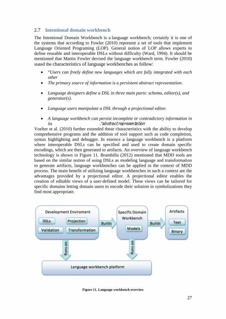
Voelter et al. (2010) further extended these characteristics with the ability to develop comprehensive programs and the addition of tool support such as code completion, syntax highlighting and debugger. In essence a language workbench is a platform where interoperable DSLs can be specified and used to create domain specific encodings, which are then generated to artifacts. An overview of language workbench technology is shown in Figure 11. Brambilla (2012) mentioned that MDD tools are based on the similar notion of using DSLs as modeling language and transformation to generate artifacts, language workbenches can be applied in the context of MDD process. The main benefit of utilizing language workbenches in such a context are the advantages provided by a projectional editor. A projectional editor enables the creation of editable views of a user-defined model. These views can be tailored for specific domains letting domain users to encode their solution in symbolizations they find most appropriate.
Figure 11. Language workbench overview
28
In the next section, section 2.8, the author will introduce some further examples regarding the language workbenches.
2.8 Different DSL tools Many different language workbenches exist for long time to build custom languages. As Voelter et al. (2010) cited, utilizing proficient tools and IDEs will help to create and integrate DSLs efficiently and may make qualitative differences. He also mentioned developing DSLs and IDEs has been decreased considerably, as the language workbenches have been developed proficiently. Nowadays, feature-rich IDEs and tools have been used more by the DSLs experts. For instance: Eclipse Modeling (Xtext), JetBrains MPS 1 , SDF/Stratego/Spoofax 2 , and the Intentional Domain Workbench3. In this section, just one of the tools, which is used in this research will be introduced.
2.8.1 Eclipse and Xtext: Eclipse4 is known as an integrated development environment (IDE) for Java. Eclipse is produced by an Open Source community at 2001 and is used in several different areas such as a development environment for Java5. Xtext6 is an open source framework for developing DSLs, which is being developed in the Eclipse platform. It is a framework for making the textual DSLs. It uses Xtend7, which is a high level and optimized programing language for the Java virtual machine. As Voelter et al. (2010) stated, Xtext might not be advanced in comparison with other existing tools, but it is very developed and has a vast support community. Furthermore, a great number of add-ons exist that support the building of complex DSL systems. It covers most of the aspects of a complete language infrastructure, from parsers, over linker, compiler or interpreter to fully-blown top-notch Eclipse IDE integration. It comes with good defaults for all these aspects and at the same time every single aspect can be tailored to experts needs.
2.9 Telecom Network at Ericsson Network management systems methodology has been used at telecommunication networks for controlling and observing network resources such as Radio Base Stations (RBSs). Now a days telecom industries try to use an object oriented approach, which the object information classification represent the network in an entity level abstraction (Venieris et al. 2000). By having this abstract representation, managing and controlling the object components and the underlying network, which are requested by operator can be handle in a better way. There are two different types of software interactions in telecom network: (1) External interaction, which is the communication between RBSs and the entire network, and (2) Internal interaction, which indicates the interaction between the software and hardware components within the RBS system. Thus when new topology requested by the customers for the
1 http://www.jetbrains.com/mps/
2 http://strategoxt.org/Spoofax
3 http://www.intentsoft.com/
4 http://www.eclipse.org/
5 Eclipse Foundation. (2014). About the Eclipse Foundation. Retrieved May 28, 2014, from: http://www.eclipse.org/org/
6 http://www.eclipse.org/Xtext/
7 http://www.eclipse.org/xtend/
29
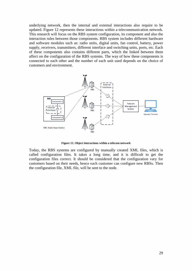
underlying network, then the internal and external interactions also require to be updated. Figure 12 represents these interactions within a telecommunication network. This research will focus on the RBS system configuration, its component and also the interaction rules between those components. RBS system includes different hardware and software modules such as: radio units, digital units, fan control, battery, power supply, receivers, transmitters, different interface and switching units, ports, etc. Each of these components also contains different parts, which the linked between them affect on the configuration of the RBS systems. The way of how these components is connected to each other and the number of each unit used depends on the choice of customers and environment.
Figure 12. Object interactions within a telecom network
Today, the RBS systems are configured by manually created XML files, which is called configuration files. It takes a long time, and it is difficult to get the configuration files correct. It should be considered that the configuration vary for customers based on their needs, hence each customer can configure new RBSs. Then the configuration file, XML file, will be sent to the node.

31
3 Research Approach This study was conducted at the Ericsson company headquarter at Kista –Stockholm. Ericsson is a Swedish multinational provider of communications technology and services. With its more than 110,000 employees in 180 countries around the world8, Ericsson offers a global service within Information and Communication Technology for telecom operators and other industries. The company was founded in 1876 by Lars Magnus Ericsson and today is a world leader in mobile network infrastructure with global market share of about 35%.
This section provides an overview of the research method used in this study. It explains the research setting and research process of this investigation. It also includes some details about the data collection and data analysis step. Finally it gives a few examples of the challenges that were faced during this industrial project.
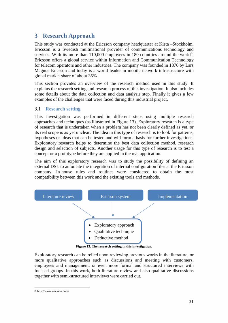
3.1 Research setting This investigation was performed in different steps using multiple research approaches and techniques (as illustrated in Figure 13). Exploratory research is a type of research that is undertaken when a problem has not been clearly defined as yet, or its real scope is as yet unclear. The idea in this type of research is to look for patterns, hypotheses or ideas that can be tested and will form a basis for further investigations. Exploratory research helps to determine the best data collection method, research design and selection of subjects. Another usage for this type of research is to test a concept or a prototype before they are applied in the real application.
The aim of this exploratory research was to study the possibility of defining an external DSL to automate the integration of internal configuration files at the Ericsson company. In-house rules and routines were considered to obtain the most compatibility between this work and the existing tools and methods.
Figure 13. The research setting in this investigation.
Exploratory research can be relied upon reviewing previous works in the literature, or more qualitative approaches such as discussions and meeting with customers, employees and management, or even more formal and structured interviews with focused groups. In this work, both literature review and also qualitative discussions together with semi-structured interviews were carried out.
8 http://www.ericsson.com/
Literature review
• Exploratory approach • Qualitative technique • Deductive method
Ericsson system
Implementation
32
This research was performed in the deductive way as it moved from general ideas and discussions toward particular cases. Reasoning together with qualitative methods were used to answer the research questions in this study. So the outcome from this work and causal correlations between the system variables should be valid in general. This means that the approach in this research is not limited to the specific application taken in this investigation and can be used in the similar applications.
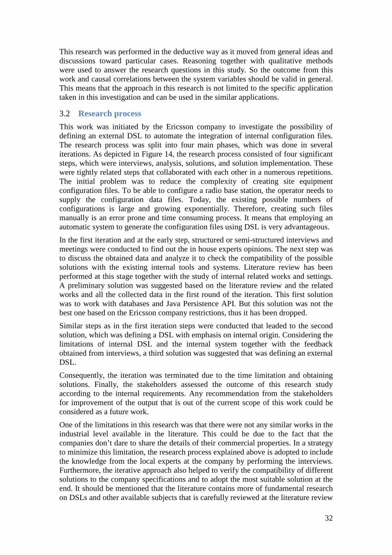
3.2 Research process This work was initiated by the Ericsson company to investigate the possibility of defining an external DSL to automate the integration of internal configuration files. The research process was split into four main phases, which was done in several iterations. As depicted in Figure 14, the research process consisted of four significant steps, which were interviews, analysis, solutions, and solution implementation. These were tightly related steps that collaborated with each other in a numerous repetitions. The initial problem was to reduce the complexity of creating site equipment configuration files. To be able to configure a radio base station, the operator needs to supply the configuration data files. Today, the existing possible numbers of configurations is large and growing exponentially. Therefore, creating such files manually is an error prone and time consuming process. It means that employing an automatic system to generate the configuration files using DSL is very advantageous.
In the first iteration and at the early step, structured or semi-structured interviews and meetings were conducted to find out the in house experts opinions. The next step was to discuss the obtained data and analyze it to check the compatibility of the possible solutions with the existing internal tools and systems. Literature review has been performed at this stage together with the study of internal related works and settings. A preliminary solution was suggested based on the literature review and the related works and all the collected data in the first round of the iteration. This first solution was to work with databases and Java Persistence API. But this solution was not the best one based on the Ericsson company restrictions, thus it has been dropped.
Similar steps as in the first iteration steps were conducted that leaded to the second solution, which was defining a DSL with emphasis on internal origin. Considering the limitations of internal DSL and the internal system together with the feedback obtained from interviews, a third solution was suggested that was defining an external DSL.
Consequently, the iteration was terminated due to the time limitation and obtaining solutions. Finally, the stakeholders assessed the outcome of this research study according to the internal requirements. Any recommendation from the stakeholders for improvement of the output that is out of the current scope of this work could be considered as a future work.
One of the limitations in this research was that there were not any similar works in the industrial level available in the literature. This could be due to the fact that the companies don’t dare to share the details of their commercial properties. In a strategy to minimize this limitation, the research process explained above is adopted to include the knowledge from the local experts at the company by performing the interviews. Furthermore, the iterative approach also helped to verify the compatibility of different solutions to the company specifications and to adopt the most suitable solution at the end. It should be mentioned that the literature contains more of fundamental research on DSLs and other available subjects that is carefully reviewed at the literature review
33
stage in this thesis. These were in the forms of scientific papers and books that a complete list of them is presented in the reference section.
Figure 14. The research process in this investigation.
3.3 Data collection There were two main data sources in this research. The first one was the literature from different sources such as journals, books, conferences and reports. A literature review was performed to check the state-of-the-art in this field. The initial step in the literature survey was to define the research problem in detail and also the final goal of the work. This helped to identify the areas that should be covered during the survey. Then the scientific databases such as IEEE Xplore, ScienceDirect and GoogleScholar were employed to search for the relevant articles and reports. Finally all the collected data was reviewed and the advantages and shortcomings of the previously performed researched were summarized. This gave a good understanding of the available knowledge and also new improvements needed to be performed in order to reach the goals of the project. As mentioned before, these scientific papers were mainly on the fundamental research topics of software engineering that provided the author the knowledge to perform this research. For instance, a comparison between the internal and external DSLs and the corresponding advantages and disadvantages for each of them is taken from the literature. A detail list of these papers is presented in the reference section.
The second data collection source in this investigation was the in-house specifications and routines in the Ericsson company, which was the originator of this project. Internal rules and routines were considered and the existing relevant documents were reviewed. Furthermore, structured or semi-structured interviews and meetings were conducted to obtain in hand experience of the company experts and their opinions. This ensured the most compatibility between the results of this work and the existing tools and methods in the company. Specifically, internal configuration files for radio base station were used to build the DSL rules that was the main goal of this project.
Implement Solutions
Interviews
Analysis
Solutions Initial problem
34
These interviews and technical meetings involved different groups of experts including system designers, system developers and managements. This diverse background provided valuable ideas and feedbacks from different points of view that were quite advantageous for the project.
3.4 Data analysis The collected data from the literature together with the company internal requirements and specifications were combined and were used as a base for this study. These data were interpreted into a meaningful content, which was then related to the objective of the project. Data analysis was performed to build a bridge between the available data and the possible solutions to reach the final goal of the project. One critical issue to be considered here, in this industrial research, was the compatibility between the suggested solution and the company internal tools and methods. This has a considerable effect on the data analysis step that was a prerequisite toward the final solution. As stated before, this research process was performed in an iterative way at different steps. Therefore the data collection and data analysis were done during each iteration. It means that each time the updated collected data was analyzed and gradually leaded to the final aim of the project. Thus the final solutions are evolved during this iteration process and are improved based on the feedback from interviews. The outcome from the above mentioned iterations leaded to three possible solutions that are compatible with company requirements. These solutions will be explained and compared in detail in section 4 and the conclusions will be drawn accordingly.
3.5 Limitations and challenges Despite the considerable internal knowledge and support from the company, performing such a research at Ericsson with its in house specifications and routines makes this work more challenging. For instance, there is an advance internal architecture that contains number connectors and components and is proven to be reliable by time. It should be mentioned that this architecture is not constrained by any specific architectural style. This specific internal architecture with its permitted platforms should be carefully followed. This means that all the architects within the company who design a system should deal with this architecture.
Another challenge in this multi-disciplinary project was to deal with different teams within the company. This makes a wider range of input and interests from different divisions and also increases the level of difficulty to perform the project in proper way. It should be mentioned that despite the DSLs have a long history within software engineering, but there is still limited number of examples in industry that this method is applied on a complex system. This resulted in a very few previous studies were found in the literature review stage. So it put an extra challenge in this project and increased the number of iterations before leading to the final solution.
35
4 Solutions As shown in Figure 14, this research consists of different iterations. Thus the final suggested solutions are evolved during this iteration process and are improved based on the feedback from interviews. The detail steps of the solutions cannot be shared by considering the limitation of distributing the properties of the Ericsson company. However, a fairly complete procedure of the solutions is presented in this section.
4.1 Solution 1 - Database The problem in this investigation is to deal with the manual configuration of RBS systems and also XML files. By using XML format, the configuration files are lengthy and it is problematic to write them manually.
The first stage to approach the problem consists of interviewees who are experts in the Ericsson company system. This step includes the interview process, data collection, and the building of the first solution. It was concluded at this stage that there high need to have a tool that can generate reliable configuration files.
As the problem focused on the object models of RBS systems, so the first solution was working with Java Persistence API (JPA) instead of directly writing SQL query to access data stores. It should be mentioned that based on the first input gathered from interviews that was aiming to have a rich domain model, a possible solution was working with the JPA framework. Because with JPA, it is possible to have all the entities as tables in the databases and also they can be modeled as classes in Java EE. In addition, it is also possible to embed behavior into these classes and thus reach an interactively rich domain model. All the RBS components, which are entities in this solution, have multiple purposes, involving the aim of replacing the data transfer objects for transporting data across the different tiers. The mapping links between the data representation in the relational databases, tables, records, representation of classes and objects in the Java EE application, was the reason to use JPA solution. Furthermore, generating and designing the database tables is quite straightforward by using JPA and java EE.
Based on the complexity of RBS configuration, it is very difficult to set the parameters and process the result by hand. Thus this solution leads to save a considerable development and debugging time from developers. As mentioned in section 2.9, RBS systems consist of several components and relations between them. Hence using JPA allows the developers to work directly with the RBS components rather than with SQL statements. Additionally, as JPA is database independent, therefore any database platform could be used regarding the Ericsson company own choice. After careful consideration, the author decided to use the PostgreSQL9, which is an object relational database. As it fulfills the entire project requirements and it is not against the Ericsson company’s limitation. Additionally in the most advanced queries, PostgreSQL is much easier to drop-in replacement for SQL server than other databases. Moreover, the ability to better aggregate data from various sources, deploying quickly, owning the own stack and having a very extendable system were also considered in selecting this solution.
9 http://www.postgresql.org/
36
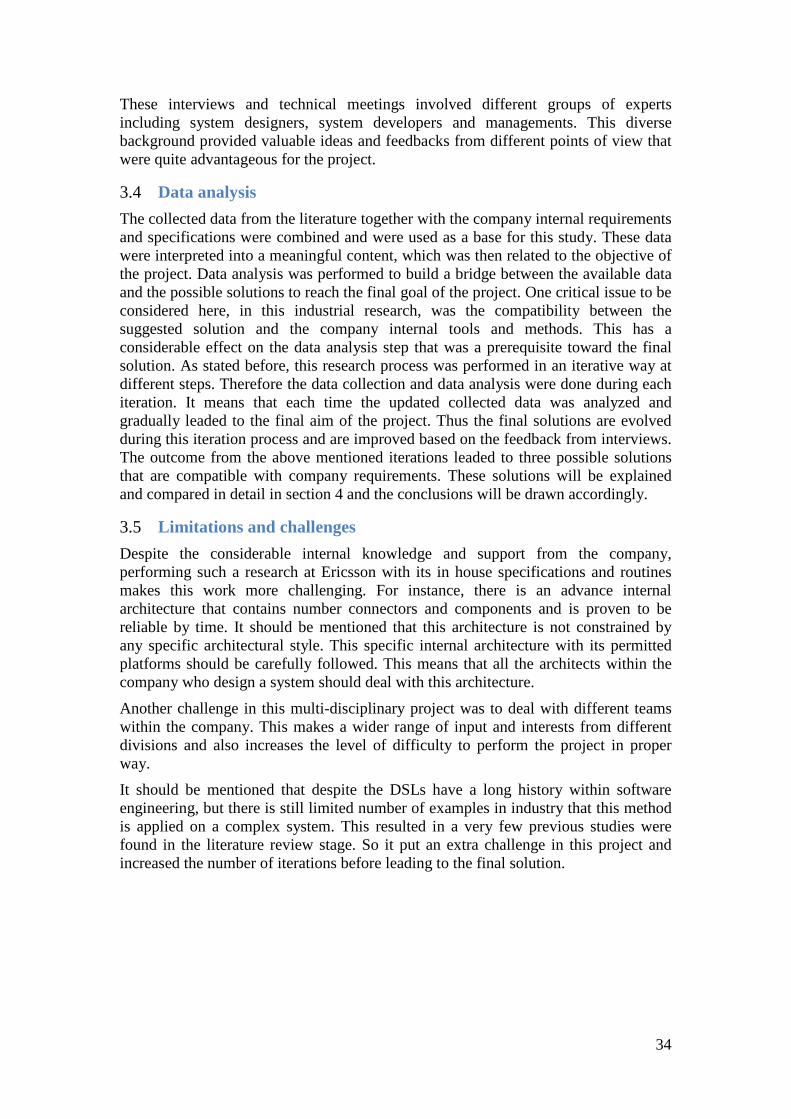
Figure 15. GUI of configuration tool
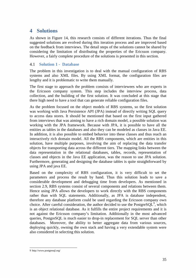
After extensive assessment, building an application was started. Firstly, UMLs were used to design the system and then implementation was performed with JPA accordingly. As it can be seen in picture Figure 15 , which is a graphical user interface of the project, customer can select different RBS configuration based on their own choice and the system filters the other components regarding to each selection. The desired data are stored in database tables. The project data tables are shown in Figure 16, which is the graphical user interface of PostgreSQL desktop application. As it is shown in the picture, for each component of RBS system, there is corresponded table. Also database tables are generated automatically, if there is any relationship between the components. So as it is clear, it is so easier to create a table for each component and add configuration specification based on the need. In addition, it would be so easier to maintain it in the future.

37
Figure 16. Database tables in PostgreSQL tool
However, after having more interviews with domain experts from different sections of the Company, the author found that this solution might not be a direct fit to the problem, especially when the data model is going to be modified regularly. One of the problems was about the complexity of the RBS configuration. Since as the hierarchy of components grows, the number of joined tables required to construct a leaf class also grows. Thus this results the poor performance. However the most important problem was about Ericsson company restrictions. It was required the tool be a stand-alone and not web-based. In addition, having a database in the server was not possible. Because the tool is given to customer, but they don’t have access to the Company servers.
Furthermore, writing the rules directly in database tables was too difficult for the developers. Another difficulty was regarding the UML diagrams. Since it forced the author to solve the same problem several times, firstly in problem domain and concepts, then UML model, and finally in the code. UML unfortunately does not raise the abstraction level further. It also does not assist the author in making correct design of the rules as it is general purpose and allows very little code to be generated. As a result, the author could not follow the UML model properly once the coding started, because of the complexity of the domain system. Although UML made a visual plan
38
of the problem and the code in advance, but it was not the best solution for this problem. Therefore after thorough thoughtfulness and having the other rounds of interviews, new company restriction in using this solution was noticed. Therefore the author decided to change the way out and go for another solution.
4.2 Solution 2 - External DSL As mentioned in the first solution, writing the rules in database tables was too difficult for the developers, since the complexity of the work did not let them to cover all the existing configurations. Hence after having the other round of interviews and based on the literature review, the author came up with the idea of using the DSL, which was quite convenient for people with different roles to read and write the appropriate expressions. In addition it covers most of the possible configuration rules.
As was discussed in section 2.1, with DSL the level of abstraction can be increased and be closer to the problem domain. This is performed not by visualizing the code, but by providing a highly tailored modeling language that visualize the problem domain and therefore guide the modelers into making correct design. Modelers design applications visually with the concept that mimic closely real objects and also enable generating the low level code from these designs. It is very important that we can target different programming languages such as Java, C++ or any other languages that are supported by Ericsson company.
As mentioned in section 2.1.2, external DSLs provide syntactic freedom, so the users can utilize any desired syntax. In addition the parsing process works on the pure text file input, which is not limited by any specific language.
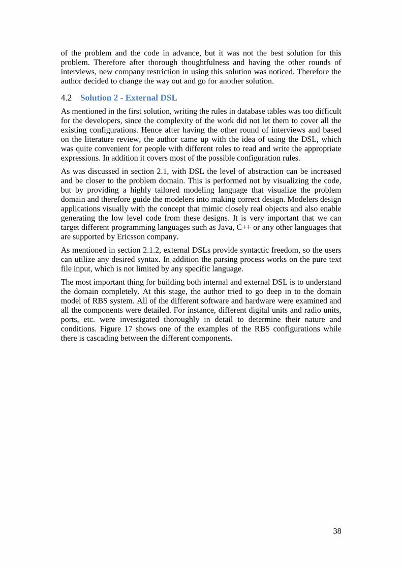
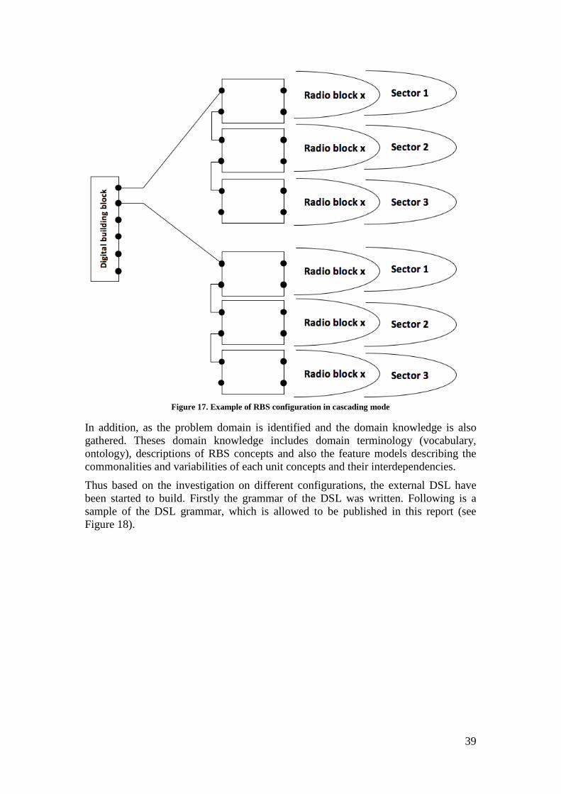
The most important thing for building both internal and external DSL is to understand the domain completely. At this stage, the author tried to go deep in to the domain model of RBS system. All of the different software and hardware were examined and all the components were detailed. For instance, different digital units and radio units, ports, etc. were investigated thoroughly in detail to determine their nature and conditions. Figure 17 shows one of the examples of the RBS configurations while there is cascading between the different components.
39
Figure 17. Example of RBS configuration in cascading mode
In addition, as the problem domain is identified and the domain knowledge is also gathered. Theses domain knowledge includes domain terminology (vocabulary, ontology), descriptions of RBS concepts and also the feature models describing the commonalities and variabilities of each unit concepts and their interdependencies.
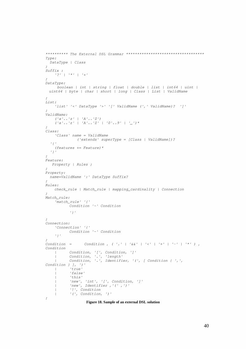
Thus based on the investigation on different configurations, the external DSL have been started to build. Firstly the grammar of the DSL was written. Following is a sample of the DSL grammar, which is allowed to be published in this report (see Figure 18).
40
********** The External DSL Grammar *********************************** Type: DataType | Class ; Suffix : '?' | '*' | '+' ; DataType: boolean | int | string | float | double | list | int64 | uint | uint64 | byte | char | short | long | Class | List | ValidName
; List: 'list' '<' DataType '>' '[' ValidName (',' ValidName)? ']' ; ValidName: ('a'..'z' | 'A'..'Z') ('a'..'z' | 'A'..'Z' | '0'..9' | '_')* ; Class: 'Class' name = ValidName ('extends' superType = [Class | ValidName])? '{' (features += Feature)* '}' ; Feature: Property | Rules ; ; Property: name=ValidName ':' DataType Suffix? ; Rules: check_rule | Match_rule | mapping_cardinality | Connection ; Match_rule: 'match_rule' '{'
Condition '~' Condition
'}'
; Connection: 'Connection' '{' Condition '~' Condition '}' ; Condition = Condition , ( '.' | '&&' | '<' | '+' | '-' | '*' ) , Condition | Condition, '[', Condition, ']' | Condition, '.', 'length' | Condition, '.', Identifier, '(', [ Condition { ',', Condition } ], ')' | 'true' | 'false' | 'this' | 'new', 'int', '[', Condition, ']' | 'new', Identifier ,'(' ,')' | '!', Condition | '(', Condition, ')' ;
Figure 18. Sample of an external DSL solution
41
Grammars are almost written in the form of EBNF, which was explained in section 2.3. Each line of the grammar is followed by the allowable elements of that rule. In the above example, the code may not be as clear as actual EBNF, but it is pretty close. It should be mentioned that most of the alteration is based on the domain requirements. One of the main risks that may occur by defining this external DSL is that it might unintentionally progress to become a GPL. If things become progressively worse, a DSL can easily become excessively complex. Especially in this project that have a lot of particular cases, which require special behavior, but are used seldom. Furthermore, above grammar, which is written in EBNF provide a human readable definitions of a language. So it makes it simpler for people to realize what an acceptable syntax in a language is. As it can be seen in the example, there are different operators have been used in this grammar such as range “..” , or “|” , brackets “[ ]”, etc. But the most important one is the end operator “;” which will help in the parsing phase.
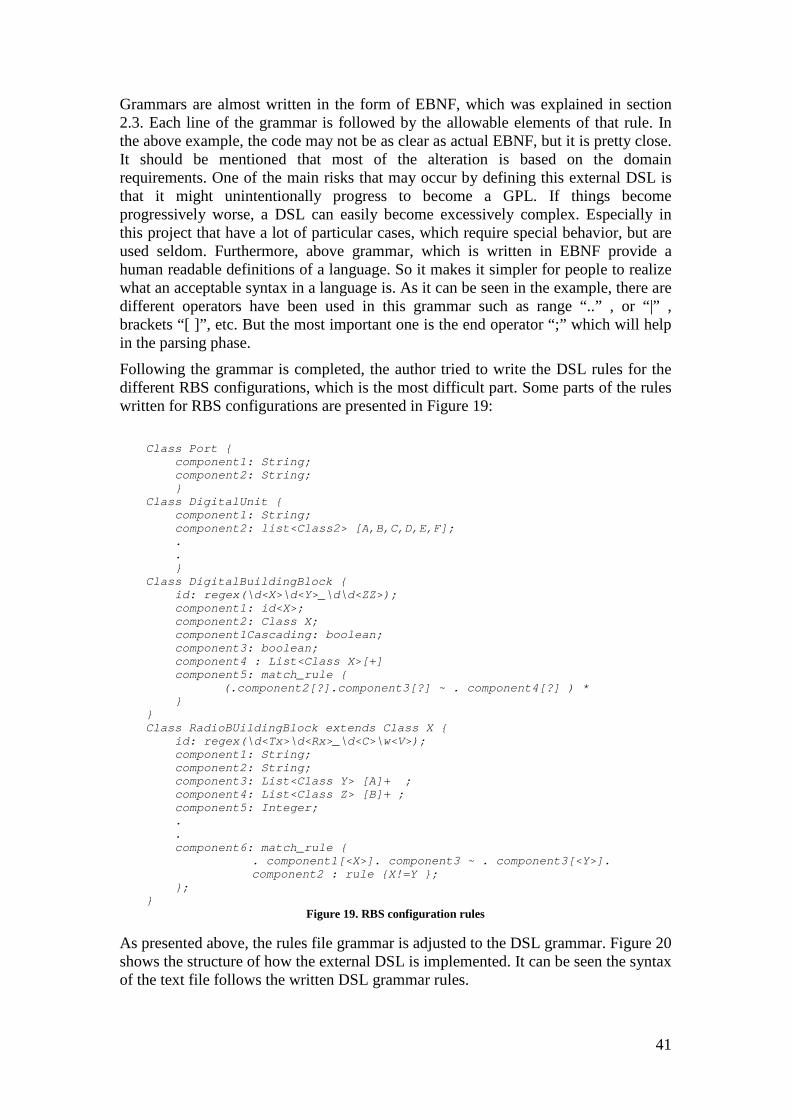
Following the grammar is completed, the author tried to write the DSL rules for the different RBS configurations, which is the most difficult part. Some parts of the rules written for RBS configurations are presented in Figure 19:
Class Port { component1: String; component2: String; } Class DigitalUnit { component1: String; component2: list<Class2> [A,B,C,D,E,F]; . . } Class DigitalBuildingBlock { id: regex(\d<X>\d<Y>_\d\d<ZZ>); component1: id<X>; component2: Class X; component1Cascading: boolean; component3: boolean; component4 : List<Class X>[+] component5: match_rule { (.component2[?].component3[?] ~ . component4[?] ) * } } Class RadioBUildingBlock extends Class X { id: regex(\d<Tx>\d<Rx>_\d<C>\w<V>); component1: String; component2: String; component3: List<Class Y> [A]+ ; component4: List<Class Z> [B]+ ; component5: Integer; . . component6: match_rule {
. component1[<X>]. component3 ~ . component3[<Y>]. component2 : rule {X!=Y };
}; }
Figure 19. RBS configuration rules
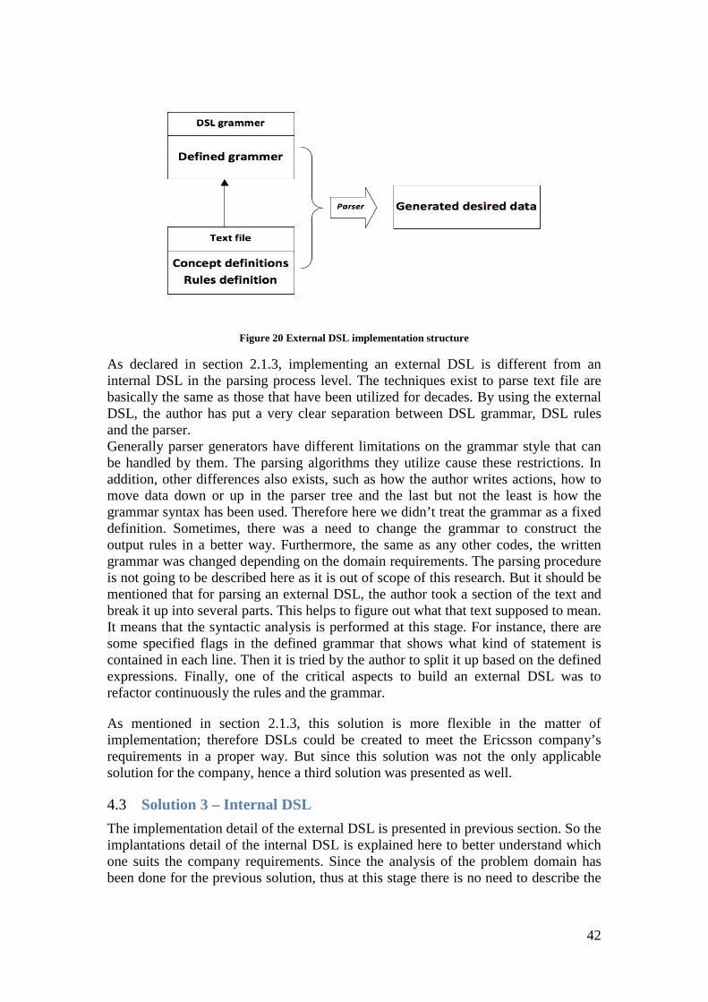
As presented above, the rules file grammar is adjusted to the DSL grammar. Figure 20 shows the structure of how the external DSL is implemented. It can be seen the syntax of the text file follows the written DSL grammar rules.
42
Figure 20 External DSL implementation structure
As declared in section 2.1.3, implementing an external DSL is different from an internal DSL in the parsing process level. The techniques exist to parse text file are basically the same as those that have been utilized for decades. By using the external DSL, the author has put a very clear separation between DSL grammar, DSL rules and the parser. Generally parser generators have different limitations on the grammar style that can be handled by them. The parsing algorithms they utilize cause these restrictions. In addition, other differences also exists, such as how the author writes actions, how to move data down or up in the parser tree and the last but not the least is how the grammar syntax has been used. Therefore here we didn’t treat the grammar as a fixed definition. Sometimes, there was a need to change the grammar to construct the output rules in a better way. Furthermore, the same as any other codes, the written grammar was changed depending on the domain requirements. The parsing procedure is not going to be described here as it is out of scope of this research. But it should be mentioned that for parsing an external DSL, the author took a section of the text and break it up into several parts. This helps to figure out what that text supposed to mean. It means that the syntactic analysis is performed at this stage. For instance, there are some specified flags in the defined grammar that shows what kind of statement is contained in each line. Then it is tried by the author to split it up based on the defined expressions. Finally, one of the critical aspects to build an external DSL was to refactor continuously the rules and the grammar.
As mentioned in section 2.1.3, this solution is more flexible in the matter of implementation; therefore DSLs could be created to meet the Ericsson company’s requirements in a proper way. But since this solution was not the only applicable solution for the company, hence a third solution was presented as well.
4.3 Solution 3 – Internal DSL The implementation detail of the external DSL is presented in previous section. So the implantations detail of the internal DSL is explained here to better understand which one suits the company requirements. Since the analysis of the problem domain has been done for the previous solution, thus at this stage there is no need to describe the
43
domain concepts again. So the information regarding the domain problem gathered in previous solution can be used to build the internal DSL.
As mentioned in section 2.1.1, internal DSL can be called embedding DSL. As DSL structures are embedded in an existing GPL by describing new abstract data types and operations. Dissimilar to an external DSL, for an internal DSL, the syntax and programming model of the host language restricts you. But there is no need to think about building a parser. Additionally, it is good that in the complicated situations, the host language features can be used.
Based on the Ericsson company requirements and literature reviews, Xtext was chosen as a tool here. As cited in section 2.8.1, Xtext is a textual Open source DSL development framework, which provides the ability to define DSL using a simple EBNF notation. Xtext will build a parser, a metamodel and a specific Eclipse text editor for defined DSL. Also it can be installed easily from Eclipse IDE, therefore it was a good choice to work with Xtext.
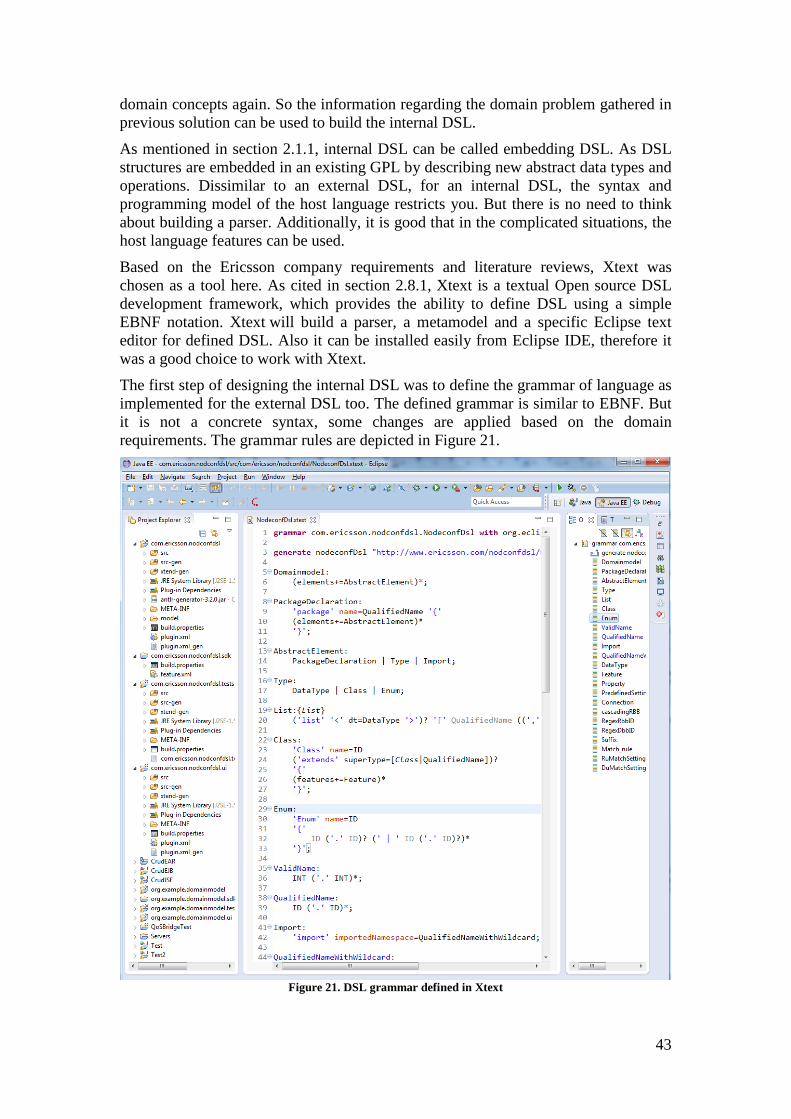
The first step of designing the internal DSL was to define the grammar of language as implemented for the external DSL too. The defined grammar is similar to EBNF. But it is not a concrete syntax, some changes are applied based on the domain requirements. The grammar rules are depicted in Figure 21.
Figure 21. DSL grammar defined in Xtext
44
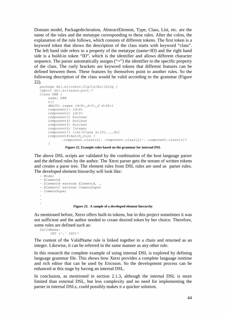
Domain model, Packagedecleration, AbstractElement, Type, Class, List, etc. are the name of the rules and the metatype corresponding to these rules. After the colon, the explanation of the rule follows, which consists of different tokens. The first token is a keyword token that shows the description of the class starts with keyword “class”. The left hand side refers to a property of the metatype (name=ID) and the right hand side is a build-in token “ID”, which is the identifier and allows different character sequence. The parser automatically assigns (“=”) the identifier to the specific property of the class. The curly brackets are keyword tokens that different features can be defined between them. These features by themselves point to another rules. So the following description of the class would be valid according to the grammar (Figure 22).
package dsl.ericsson.DigitalBuilding { import dsl.ericsson.port.* Class DBB { name: DBB n:1 dbbID: regex (d<X>_d<Y>_d d<ZZ>) component1: id<X> component2: id<Y> component3: boolean component4: boolean component5: boolean component6: Integer component7: list<Class x>[S1,..,Sn] component8:match_rule { .component.class[x]. component.class[y]~. component.class[z]} }
Figure 22. Example rules based on the grammar for internal DSL
The above DSL scripts are validated by the combination of the host language parser and the defined rules by the author. The Xtext parser gets the stream of written tokens and creates a parse tree. The element rules from DSL rules are used as parser rules. The developed element hierarchy will look like:
- Model - ElementA - ElementB extends ElementA, … - ElementC extends CommonSuper - CommonSuper . . .
Figure 23. A sample of a developed element hierarchy
As mentioned before, Xtext offers built-in tokens, but in this project sometimes it was not sufficient and the author needed to create desired token by her choice. Therefore, some rules are defined such as:
ValidName: INT ('.' INT)*
The content of the ValidName rule is linked together in a chain and returned as an integer. Likewise, it can be referred in the same manner as any other rule.
In this research the complete example of using internal DSL is explored by defining language grammar file. This shows how Xtext provides a complete language runtime and rich editor that can be used by Ericsson. So the development process can be enhanced at this stage by having an internal DSL.
In conclusion, as mentioned in section 2.1.3, although the internal DSL is more limited than external DSL, but less complexity and no need for implementing the parser in internal DSLs, could possibly makes it a quicker solution.
45
4.4 Reflections This study was set out to explore the challenges of defining an external and internal DSL to reduce the complexity for creating RBS configuration. As a non-disclosure agreement was signed, consequently more detailed information about the structure of the Ericsson DSL rules model and related documents cannot be shared. However the result of this study was shared as far as possible in this report without going into details.
The DSL solutions mentioned in section 4.2 and 4.3 were compared against by considering the company’s requirements. The solutions are similar in fundamental parts as each of them consists of grammar syntaxes and their relations, which will be used to write the rules. Due to these similarities, the author argues that both of these solutions can be used by the Ericsson company. It should be mentioned that using both DSLs solutions obtained positive feedback in the company and can be fully applied in the company. However, depending on the other requirements from stakeholders, one solution should be selected later.

47
5 Conclusion The purpose of this study was to explore the possibilities of how to transfer from a manually build RBS configuration toward a more automated and reliable system configuration. In order to reach the aim of this study, different solutions are investigated. External and Internal DSL, as an effective method to handle complicated system in a simple manner, are studied in detail based on internal requirements of the Ericsson company. As explained in section 2.1, defining DSLs raises the quality of the product and consequently increases the maintainability of the system. Also another alternative technique, database solution, was considered in addition to DSL solutions to ensure that the most effective possible one that leads the final goal of the project is selected. But due to the company internal restrictions, which the customers cannot access to the Company database server, this solution was identified as less suitable one.
During the construction process, the author came to the conclusion that there is not only one DSL solution, which suits the company requirements. Therefore, both Internal and External DSL were considered beneficial and one can be followed depends on desires of the Ericsson company. For example, if there is not a critical need to implement the specific parser for the DSL, then it is recommended to utilize the defined internal DSL. On the other hand, to obtain a more flexible tool that suits the complex system of the company, using an External DSL is recommended. Therefore this means that both methods are capable to fulfill the needs of the company for this project. However, all specific project requirements such as cost and schedule (which is out of the scope of this work) to be considered to decide which solution is more acceptable for the Company.
6 Future work The outcome of this thesis work is going to be used as a validation part of a specific tool within the Company. The desired customer RBS configuration as an input to the tool is going to be validated against the defined DSL. Although the defined DSL rules will be updated more often than the tool based on the upcoming RBS configuration in the future. It should be mentioned here that frequently updating the RBS configuration is one of the main reason to choose a DSL solutions over the other techniques.
The main focus of this study was on the RBS configurations. Therefore in terms of future improvement for this work, Antenna configuration could be included. This will be another important step toward having the same input format for different components within the Company. Furthermore, it is recommended to have a deeper investigation on the overall factors that affect the run-time behavior and user experience. This ensures to reach a higher quality of the tool in the future. Because the main focus of this project, due to the time plan, was to develop the system design and the process of defining the components, modules and data for the DSLs to satisfy the indicated requirements. Therefore, including the overall factors that influence the system behavior and were out of scope of this thesis work is essential in the future.

49
7 References
Bahlke, Rolf, and Gregor Snelting. 1986. “The PSG System: From Formal Language Definitions to Interactive Programming Environments.” ACM Transactions on Programming Languages and Systems (TOPLAS) 8 (4): 547–576.
Ballance, Robert A, Susan L Graham, and Michael L Van De Vanter. 1990. The Pan Language-Based Editing System for Integrated Development. Vol. 15. ACM.
Bass, Len, Paul Clements, and Rick Kazman. 2003. Software Architecture in Practice. Addison-Wesley Professional.
Batori, Gabor, Zoltan Theisz, and Domonkos Asztalos. 2005. “Robust Reconfigurable Erlang Component System.” In Erlang User Conference.
Brambilla, Marco, Jordi Cabot, and Manuel Wimmer. 2012. “Model-Driven Software Engineering in Practice.” Synthesis Lectures on Software Engineering 1 (1): 1–182.
Chamberlin, Donald D, and Raymond F Boyce. 1974. “SEQUEL: A Structured English Query Language.” In Proceedings of the 1974 ACM SIGFIDET (now SIGMOD) Workshop on Data Description, Access and Control, 249–264. ACM.
Crnkovic, Ivica. 2001. “Component‐based Software Engineering—new Challenges in Software Development.” Software Focus 2 (4): 127–133.
Curtis, Bill, Herb Krasner, and Neil Iscoe. 1988. “A Field Study of the Software Design Process for Large Systems.” Communications of the ACM 31 (11): 1268–1287.
Czarnecki, Krzysztof. 2002. “Generative Programming: Methods, Techniques, and Applications Tutorial Abstract.” In Software Reuse: Methods, Techniques, and Tools, 351–352. Springer.
Evans, Eric. 2004. Domain-Driven Design: Tackling Complexity in the Heart of Software. Addison-Wesley Professional.
Fowler, Martin. 2010. Domain-Specific Languages. Pearson Education.
Garshol, Lars Marius. 2005. “BNF and EBNF: What Are They and How Do They Work.” Acedida Pela Última Vez Em 16.
Ghezzi, Carlo, Mehdi Jazayeri, and Dino Mandrioli. 2002. Fundamentals of Software Engineering. Prentice Hall PTR.
Ghosh, Debasish. 2010. DSLs in Action. Manning Publications Co.
Gray, Jeff, Kathleen Fisher, Charles Consel, Gabor Karsai, Marjan Mernik, and Juha-Pekka Tolvanen. 2008. “DSLs: The Good, the Bad, and the Ugly.” In Companion to the 23rd ACM SIGPLAN Conference on Object-Oriented Programming Systems Languages and Applications, 791–794. ACM.
50
Gunther, Sebastian, Maximilian Haupt, and Matthias Splieth. 2010. “Agile Engineering of Internal Domain-Specific Languages with Dynamic Programming Languages.” In Software Engineering Advances (ICSEA), 2010 Fifth International Conference on, 162–168. IEEE.
Günther, Sebastian. 2009. “Agile DSL-Engineering and Patterns in Ruby.” Otto-von-Guericke-Universität Magdeburg, Technical Report (Internet) FIN-018-2009.
Heckerman, David, David Maxwell Chickering, Christopher Meek, Robert Rounthwaite, and Carl Kadie. 2001. “Dependency Networks for Inference, Collaborative Filtering, and Data Visualization.” The Journal of Machine Learning Research 1: 49–75.
Hudak, Paul. 1998. “Modular Domain Specific Languages and Tools.” In Software Reuse, 1998. Proceedings. Fifth International Conference on, 134–142. IEEE.
Jennings, Nicholas R. 2001. “An Agent-Based Approach for Building Complex Software Systems.” Communications of the ACM 44 (4): 35–41.
Krueger, Charles W. 1992. “Software Reuse.” ACM Computing Surveys (CSUR) 24 (2): 131–183.
Lamport, Leslie, Dahlia Malkhi, and Lidong Zhou. 2010. “Reconfiguring a State Machine.” ACM SIGACT News 41 (1): 63–73.
McCracken, Daniel D, and Edwin D Reilly. 2003. “Backus-Naur Form (bnf).”
Mernik, Marjan, Jan Heering, and Anthony M Sloane. 2005. “When and How to Develop Domain-Specific Languages.” ACM Computing Surveys (CSUR) 37 (4): 316–344.
Nakata, Junichi, Takehiro Sugita, and Mie Tajima. 2000. “Telecommunication System, Radio Base Station Thereof, and Portable Telecommunication Terminal Thereof”. Google Patents.
Pattis, Richard E. 1980. “EBNF: A Notation to Describe Syntax.” (Online) 10 Apr. 2015, <http://www.cs.cmu.edu/~pattis/misc/ebnf.pdf>.
Quinlan, J Ross. 1987. “Generating Production Rules from Decision Trees.” In IJCAI, 87:304–307. Citeseer.
Selic, Bran. 2003. “The Pragmatics of Model-Driven Development.” IEEE Software 20 (5): 19–25.
Van Deursen, Arie, and Paul Klint. 1998. “Little Languages: Little Maintenance?” Journal of Software Maintenance 10 (2): 75–92.
Van Deursen, Arie, and Paul Klint. 2002. “Domain-Specific Language Design Requires Feature Descriptions.” CIT. Journal of Computing and Information Technology 10 (1): 1–17.
Van Deursen, Arie, Paul Klint, and Joost Visser. 2000. “Domain-Specific Languages: An Annotated Bibliography.” Sigplan Notices 35 (6): 26–36.
Vanthienen, Jan, and Geert Wets. 1994. “From Decision Tables to Expert System Shells.” Data & Knowledge Engineering 13 (3): 265–282.
51
Ward, Martin P. 1994. “Language-Oriented Programming.” Software-Concepts and Tools 15 (4): 147–161.
Venieris, Iakovos, Fabrizio Zizza, and Thomas Magedanz. 2000. “Object Oriented Software Technologies in Telecommunications From Theory to Practice.”
Voelter, Markus, Sebastian Benz, Christian Dietrich, Birgit Engelmann, Mats Helander, Lennart C L Kats, Eelco Visser, and Guido Wachsmuth. 2013. DSL Engineering-Designing, Implementing and Using Domain-Specific Languages. dslbook. org.