modelling method extension for service-oriented business process
TRANSCRIPT
Modelling Method Extension for Service-Oriented BusinessProcess Management
Dissertation
zur Erlangung des akademischen GradesDoktor der Ingenieurwissenschaften
(Dr.-Ing.)
der Technischen Fakultätder Christian-Albrechts-Universität zu Kiel
Sebastian Stein
KielDezember 2008

1. Gutachter: Prof. Dr. Andreas Speck2. Gutachter: Prof. Dr. Witold AbramowiczDatum der mündlichen Prüfung: 11. Dezember 2009
Abstract
The introduction of service-oriented architectures (SOA) in the enterprise context promisesmany advantages. For example, by composing existing services new capabilities can beprovided quickly allowing a fast and agile reaction to changing market conditions.
In order to support companies in a successful adoption of SOA, service-orientation mustbe integrated in their enterprise architecture. Many companies made high investmentsin the past modelling their enterprise architecture based on different modelling methods.The introduction of SOA is fostered if existing models can be reused and investments arepreserved. Therefore, existing modelling methods must be extended by service-orientedconcepts.
This thesis extends the modelling method ARIS with concepts for service-oriented busi-ness process management. It contributes a graphical modelling language, which is tightlyintegrated with the existing ARIS modelling method.
Besides a modelling language, a modelling method also consists of algorithms andapplications using the content captured in the models. Therefore, this thesis developsthree distinct applications based on the contributed modelling language. First, servicediscovery enables identifying services needed for business process automation. Second,the automated EPC to BPEL model transformation allows transforming a business processinto an executable service orchestration. Third, semantic business process managementformalises enterprise models so that they are machine processable.
To evaluate the usefulness of the designed modelling language and the developed ap-plications, two empirical case studies are conducted. The first case study evaluates themodelling language together with the applications service discovery and process trans-formation. The second case study evaluates the application semantic business processmanagement.
Both case studies demonstrate the usefulness and relevance of the modelling languageas well as its applications. Hence, companies introducing service-oriented concepts canuse the extended ARIS modelling method to document and analyse their service-orientedenterprise architecture.

Contents
1 Introduction 11.1 Motivation . . . . . . . . . . . . . . . . . . . . . . . . . . . . . . . . . . . 11.2 Contribution . . . . . . . . . . . . . . . . . . . . . . . . . . . . . . . . . 3
1.2.1 Theses . . . . . . . . . . . . . . . . . . . . . . . . . . . . . . . . 31.2.2 Derived Contributions . . . . . . . . . . . . . . . . . . . . . . . . . 3
1.3 Epistemological Standpoint . . . . . . . . . . . . . . . . . . . . . . . . . 51.4 Research Design . . . . . . . . . . . . . . . . . . . . . . . . . . . . . . . 61.5 Outline . . . . . . . . . . . . . . . . . . . . . . . . . . . . . . . . . . . . 8
2 State of the Art 102.1 Business Process Management . . . . . . . . . . . . . . . . . . . . . . . 10
2.1.1 Overview . . . . . . . . . . . . . . . . . . . . . . . . . . . . . . . 102.1.2 Enterprise Modelling and Enterprise Architecture Frameworks . . . 112.1.3 Modelling Method ARIS . . . . . . . . . . . . . . . . . . . . . . . . 122.1.4 Business Process Modelling . . . . . . . . . . . . . . . . . . . . . 142.1.5 Business Process Automation . . . . . . . . . . . . . . . . . . . . 16
2.2 Service-Oriented Architecture . . . . . . . . . . . . . . . . . . . . . . . . 172.2.1 Overview . . . . . . . . . . . . . . . . . . . . . . . . . . . . . . . 172.2.2 Technological SOA . . . . . . . . . . . . . . . . . . . . . . . . . . 172.2.3 Service-Orientation as Management Concept . . . . . . . . . . . . 19
2.3 Model-Driven Integration Engineering . . . . . . . . . . . . . . . . . . . . 212.3.1 Overview . . . . . . . . . . . . . . . . . . . . . . . . . . . . . . . 212.3.2 Model-Driven Architecture . . . . . . . . . . . . . . . . . . . . . . 222.3.3 OrViA Framework . . . . . . . . . . . . . . . . . . . . . . . . . . . 222.3.4 Model Checking . . . . . . . . . . . . . . . . . . . . . . . . . . . . 24
2.4 Business Process Transformation . . . . . . . . . . . . . . . . . . . . . . 252.4.1 Overview . . . . . . . . . . . . . . . . . . . . . . . . . . . . . . . 252.4.2 Business to IT Transformation Process . . . . . . . . . . . . . . . . 252.4.3 Variation Points and Transformation Issues . . . . . . . . . . . . . 262.4.4 Control Flow Centred Approaches . . . . . . . . . . . . . . . . . . 282.4.5 Approaches Based on Domain-Specific Language Extensions . . . 292.4.6 Approaches Based on Frameworks . . . . . . . . . . . . . . . . . 302.4.7 Evaluation . . . . . . . . . . . . . . . . . . . . . . . . . . . . . . . 30
2.5 Service Discovery . . . . . . . . . . . . . . . . . . . . . . . . . . . . . . 322.5.1 Overview . . . . . . . . . . . . . . . . . . . . . . . . . . . . . . . 32
I

Contents
2.5.2 Approaches for Service Discovery . . . . . . . . . . . . . . . . . . 332.5.3 Strategies for Discovery Result Combination . . . . . . . . . . . . . 342.5.4 Service Discovery Process . . . . . . . . . . . . . . . . . . . . . . 35
2.6 Semantic Business Process Management . . . . . . . . . . . . . . . . . . 352.6.1 Motivation . . . . . . . . . . . . . . . . . . . . . . . . . . . . . . . 352.6.2 Use-Cases of Semantics in Business Process Management . . . . 362.6.3 Ontologies for Semantic Business Process Management . . . . . . 372.6.4 Methodology and Applications . . . . . . . . . . . . . . . . . . . . 392.6.5 Tools for Semantic Business Process Management . . . . . . . . . 402.6.6 Evaluation . . . . . . . . . . . . . . . . . . . . . . . . . . . . . . . 41
3 Modelling Language for Service-Oriented Business Process Management 423.1 Overview . . . . . . . . . . . . . . . . . . . . . . . . . . . . . . . . . . . 43
3.1.1 Motivation . . . . . . . . . . . . . . . . . . . . . . . . . . . . . . . 433.1.2 Constraints . . . . . . . . . . . . . . . . . . . . . . . . . . . . . . 433.1.3 ARIS Extension Development Process . . . . . . . . . . . . . . . . 44
3.2 Use Cases to be Supported . . . . . . . . . . . . . . . . . . . . . . . . . 453.2.1 Overview . . . . . . . . . . . . . . . . . . . . . . . . . . . . . . . 453.2.2 Service Discovery . . . . . . . . . . . . . . . . . . . . . . . . . . 463.2.3 Service Composition . . . . . . . . . . . . . . . . . . . . . . . . . 463.2.4 Service Substitution . . . . . . . . . . . . . . . . . . . . . . . . . 473.2.5 Service Governance and Management . . . . . . . . . . . . . . . . 47
3.3 Service Description Systematic . . . . . . . . . . . . . . . . . . . . . . . 483.3.1 Aspects and Views . . . . . . . . . . . . . . . . . . . . . . . . . . 483.3.2 Levels . . . . . . . . . . . . . . . . . . . . . . . . . . . . . . . . . 493.3.3 Service Categories . . . . . . . . . . . . . . . . . . . . . . . . . . 50
3.4 SOA Meta Model . . . . . . . . . . . . . . . . . . . . . . . . . . . . . . . 533.5 Service Description Elements . . . . . . . . . . . . . . . . . . . . . . . . 55
3.5.1 Overview . . . . . . . . . . . . . . . . . . . . . . . . . . . . . . . 553.5.2 Capability . . . . . . . . . . . . . . . . . . . . . . . . . . . . . . . 553.5.3 Service Type . . . . . . . . . . . . . . . . . . . . . . . . . . . . . 563.5.4 Service Owner . . . . . . . . . . . . . . . . . . . . . . . . . . . . 563.5.5 Non-Functional Description . . . . . . . . . . . . . . . . . . . . . . 563.5.6 Data Description . . . . . . . . . . . . . . . . . . . . . . . . . . . 583.5.7 Service Architecture . . . . . . . . . . . . . . . . . . . . . . . . . 583.5.8 Available Realisations . . . . . . . . . . . . . . . . . . . . . . . . 583.5.9 Strategy Alignment . . . . . . . . . . . . . . . . . . . . . . . . . . 593.5.10 Project Management Alignment . . . . . . . . . . . . . . . . . . . 593.5.11 Usage in Processes . . . . . . . . . . . . . . . . . . . . . . . . . 593.5.12 Service Availability . . . . . . . . . . . . . . . . . . . . . . . . . . 60
3.6 ARIS Modelling Method Extension . . . . . . . . . . . . . . . . . . . . . . 603.6.1 Overview . . . . . . . . . . . . . . . . . . . . . . . . . . . . . . . 603.6.2 Gap Analysis . . . . . . . . . . . . . . . . . . . . . . . . . . . . . 613.6.3 New or Changed Object and Symbol Types . . . . . . . . . . . . . 623.6.4 Changed Model Types . . . . . . . . . . . . . . . . . . . . . . . . 64
II

Contents
3.7 Example . . . . . . . . . . . . . . . . . . . . . . . . . . . . . . . . . . . 69
4 Service Discovery 724.1 Motivation . . . . . . . . . . . . . . . . . . . . . . . . . . . . . . . . . . . 724.2 Overall Approach to Service Discovery . . . . . . . . . . . . . . . . . . . 744.3 Structural Matching Algorithm . . . . . . . . . . . . . . . . . . . . . . . . 754.4 Semantic Matching Algorithm . . . . . . . . . . . . . . . . . . . . . . . . 774.5 Service Assessment and Refinement . . . . . . . . . . . . . . . . . . . . 784.6 Example . . . . . . . . . . . . . . . . . . . . . . . . . . . . . . . . . . . 79
5 Automated EPC to BPEL Transformation 825.1 Introduction . . . . . . . . . . . . . . . . . . . . . . . . . . . . . . . . . . 825.2 Business to IT Transformation Framework . . . . . . . . . . . . . . . . . . 84
5.2.1 Axiom . . . . . . . . . . . . . . . . . . . . . . . . . . . . . . . . . 845.2.2 Axiom’s Consequences and Requirements from the Field . . . . . . 845.2.3 Framework . . . . . . . . . . . . . . . . . . . . . . . . . . . . . . 86
5.3 Control Flow Transformation . . . . . . . . . . . . . . . . . . . . . . . . . 875.4 Data Transformation . . . . . . . . . . . . . . . . . . . . . . . . . . . . . 895.5 Functional Transformation . . . . . . . . . . . . . . . . . . . . . . . . . . 89
5.5.1 Transformation of Service Information . . . . . . . . . . . . . . . . 895.5.2 Synchronous and Asynchronous BPEL Processes . . . . . . . . . 915.5.3 Service Interface Generation . . . . . . . . . . . . . . . . . . . . . 915.5.4 Support for Proprietary BPEL Extensions . . . . . . . . . . . . . . 92
5.6 Merge Support . . . . . . . . . . . . . . . . . . . . . . . . . . . . . . . . 93
6 Case Study: Model-Driven Business Process Automation 946.1 Introduction . . . . . . . . . . . . . . . . . . . . . . . . . . . . . . . . . . 946.2 Research Aim . . . . . . . . . . . . . . . . . . . . . . . . . . . . . . . . 966.3 Scenario: Electronic Access to Register of Residents . . . . . . . . . . . . 966.4 Case Study . . . . . . . . . . . . . . . . . . . . . . . . . . . . . . . . . . 98
6.4.1 Overview . . . . . . . . . . . . . . . . . . . . . . . . . . . . . . . 986.4.2 Structured Requirements Analysis . . . . . . . . . . . . . . . . . . 986.4.3 Validation . . . . . . . . . . . . . . . . . . . . . . . . . . . . . . . 1006.4.4 Transformation and Execution . . . . . . . . . . . . . . . . . . . . 101
6.5 Results . . . . . . . . . . . . . . . . . . . . . . . . . . . . . . . . . . . . 1016.5.1 Case Study Domain . . . . . . . . . . . . . . . . . . . . . . . . . 1016.5.2 Structured Requirements Analysis . . . . . . . . . . . . . . . . . . 1026.5.3 Transformation and Execution . . . . . . . . . . . . . . . . . . . . 1036.5.4 Validation . . . . . . . . . . . . . . . . . . . . . . . . . . . . . . . 1036.5.5 Tool Chain . . . . . . . . . . . . . . . . . . . . . . . . . . . . . . 1046.5.6 Concluding Remarks . . . . . . . . . . . . . . . . . . . . . . . . . 104
7 Semantic Business Process Management 1067.1 Motivation . . . . . . . . . . . . . . . . . . . . . . . . . . . . . . . . . . . 1077.2 Solution Overview . . . . . . . . . . . . . . . . . . . . . . . . . . . . . . 107
III

Contents
7.3 Semantic ARIS Software Tools . . . . . . . . . . . . . . . . . . . . . . . . 1087.3.1 Overview . . . . . . . . . . . . . . . . . . . . . . . . . . . . . . . 1087.3.2 Representation of Semantics in ARIS . . . . . . . . . . . . . . . . 1087.3.3 Selecting a WSMO Goal in ARIS . . . . . . . . . . . . . . . . . . . 1097.3.4 Completing the Data Flow . . . . . . . . . . . . . . . . . . . . . . 1107.3.5 Injecting Semantic Annotations in BPEL . . . . . . . . . . . . . . . 111
7.4 Semantic Execution Environment . . . . . . . . . . . . . . . . . . . . . . 1127.4.1 Overview . . . . . . . . . . . . . . . . . . . . . . . . . . . . . . . 1127.4.2 Semantic Invocation Service . . . . . . . . . . . . . . . . . . . . . 1127.4.3 Execution Principle . . . . . . . . . . . . . . . . . . . . . . . . . . 116
8 Case Study: Semantic Business Process Management 1188.1 Introduction . . . . . . . . . . . . . . . . . . . . . . . . . . . . . . . . . . 1188.2 Research Aim . . . . . . . . . . . . . . . . . . . . . . . . . . . . . . . . 1198.3 Scenario: VoIP Ordering Process of Telekomunikacja Polska . . . . . . . . 1198.4 Case Study . . . . . . . . . . . . . . . . . . . . . . . . . . . . . . . . . . 121
8.4.1 Overview . . . . . . . . . . . . . . . . . . . . . . . . . . . . . . . 1218.4.2 Semantic Tutorial . . . . . . . . . . . . . . . . . . . . . . . . . . . 1218.4.3 Participants . . . . . . . . . . . . . . . . . . . . . . . . . . . . . . 1228.4.4 Questionnaire . . . . . . . . . . . . . . . . . . . . . . . . . . . . . 122
8.5 Results . . . . . . . . . . . . . . . . . . . . . . . . . . . . . . . . . . . . 1248.5.1 Overview . . . . . . . . . . . . . . . . . . . . . . . . . . . . . . . 1248.5.2 Understanding Semantics . . . . . . . . . . . . . . . . . . . . . . 1248.5.3 Getting Familiar With the Domain . . . . . . . . . . . . . . . . . . 1248.5.4 Visualisation of Ontologies . . . . . . . . . . . . . . . . . . . . . . 1258.5.5 Selecting WSMO Goals . . . . . . . . . . . . . . . . . . . . . . . . 1258.5.6 Completing the Data Flow . . . . . . . . . . . . . . . . . . . . . . 1268.5.7 Motivating Service Binding During Runtime . . . . . . . . . . . . . 1278.5.8 Advantages and Disadvantages of Semantic Approach . . . . . . . 1278.5.9 Feasibility of Semantic Approach for Business Experts . . . . . . . 128
9 Conclusions 1299.1 Summary . . . . . . . . . . . . . . . . . . . . . . . . . . . . . . . . . . . 1299.2 Theses Fulfilment . . . . . . . . . . . . . . . . . . . . . . . . . . . . . . 1309.3 Future Work . . . . . . . . . . . . . . . . . . . . . . . . . . . . . . . . . 131
Bibliography 132
List of Figures 151
List of Tables 153
Glossary 154
IV

Chapter
1 Introduction
This chapter introduces the thesis by first providing the motivation for the research con-ducted in section 1.1. Based on this motivation, section 1.2 describes the main con-tributions of this thesis. Section 1.3 first clarifies the epistemological standpoint of theauthor and briefly describes the research methods applied. This is further extended insection 1.4 by a discussion of measures taken to ensure a high validity of the researchresults achieved. At the end of this chapter, the overall structure of this thesis is presentedin section 1.5.
1.1 Motivation
Besides employees and their qualification, business processes are a core asset of everycompany. The imitation of products by competitors is easier than imitation of business pro-cesses, because the complete design of business processes is not visible to an externalobserver [SS08a]. Therefore, companies can create a significant competitive advantagethrough excellent business processes. To accomplish this vision of business process ex-cellence, companies invest in the management and improvement of their business pro-cesses by applying business process management [SS08a, BKR05, SF03].
As a discipline of business process management, business process automation triesto automate at least parts of a business process using IT. Here, the use of web servicesand combining them in a service orchestration is a promising approach [Ley04]. Such anapproach to business process automation requires the introduction of a service-orientedarchitecture (SOA) [SN96, Erl05, KBS05, MSJL06]. IT capabilities available in the com-pany’s IT landscape are encapsulated as web services published on the company’s net-work.
Different modelling languages like BPMN [OMG06] and EPC [KNS92, STA05] are usedin business process management and SOA to document the business processes and ser-vice orchestrations. As a matter of fact, companies have invested in past years in doc-umenting their business processes. While introducing SOA concepts to the company’s
1
Chapter 1 Introduction
Algorithms &
Applications
Modelling
Method
Modelling
Technique
Modelling
Procedure
Modelling
Language
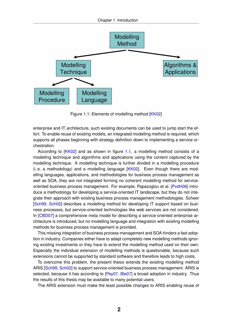
Figure 1.1: Elements of modelling method [KK02]
enterprise and IT architecture, such existing documents can be used to jump start the ef-fort. To enable reuse of existing models, an integrated modelling method is required, whichsupports all phases beginning with strategy definition down to implementing a service or-chestration.
According to [KK02] and as shown in figure 1.1, a modelling method consists of amodelling technique and algorithms and applications using the content captured by themodelling technique. A modelling technique is further divided in a modelling procedure(i. e. a methodology) and a modelling language [KK02]. Even though there are mod-elling languages, applications, and methodologies for business process management aswell as SOA, they are not integrated forming no coherent modelling method for service-oriented business process management. For example, Papazoglou et al. [PvdH06] intro-duce a methodology for developing a service-oriented IT landscape, but they do not inte-grate their approach with existing business process management methodologies. Scheer[Sch99, Sch02] describes a modelling method for developing IT support based on busi-ness processes, but service-oriented technologies like web services are not considered.In [CBD07] a comprehensive meta model for describing a service-oriented enterprise ar-chitecture is introduced, but no modelling language and integration with existing modellingmethods for business process management is provided.
This missing integration of business process management and SOA hinders a fast adop-tion in industry. Companies either have to adapt completely new modelling methods ignor-ing existing investments or they have to extend the modelling method used on their own.Especially the individual extension of modelling methods is questionable, because suchextensions cannot be supported by standard software and therefore leads to high costs.
To overcome this problem, the present thesis extends the existing modelling methodARIS [Sch99, Sch02] to support service-oriented business process management. ARIS isselected, because it has according to [Pey07, Ble07] a broad adoption in industry. Thusthe results of this thesis may be available to many potential users.
The ARIS extension must make the least possible changes to ARIS enabling reuse of
2
Chapter 1 Introduction
existing models. This lowers the adoption costs for companies and it preserves previous in-vestments. In addition, the extension must ensure that a transition from a service-orientedenterprise architecture to a service-oriented IT architecture is possible and supported.This is required to prevent a new divide between business and IT.
1.2 Contribution
1.2.1 Theses
The motivation shows that an integrated approach to service-oriented business processmanagement is missing. Therefore, this thesis aims at providing such an approach. Thework presented is based on the following theses:
1. An integrated modelling method is required, which does not just cover technicalSOA artefacts like web services, but which also provides modelling constructs for aservice-oriented enterprise architecture.
2. The modelling language to be developed as part of the modelling method will consistof several layers and will feature different notions of service concepts.
3. The service concepts of the modelling language must be flexible enough to not justcover syntactical service information, but also semantic business descriptions.
4. An algorithm or application is needed to transform content on one layer of the mod-elling language to content of another layer.
5. An algorithm or application must be provided to support business experts in select-ing an appropriate service for a specific modelling situation.
6. The modelling language must be extensible allowing custom description elementssuch as ontologies.
7. The modelling method must be integrated with existing modelling methods for busi-ness process and enterprise architecture management to ensure quick industrialadoption.
This thesis focuses on implementing those theses by providing several contributions.The following subsection presents the main contributions provided by this thesis.
1.2.2 Derived Contributions
This thesis extends the modelling method ARIS to also support service-oriented businessprocess management. The scientific contribution of this thesis is structured according tothe elements of a modelling method as defined by [KK02]. The contribution comprises thefollowing points, which are mapped in figure 1.2 to the elements of a modelling method:
3

Chapter 1 Introduction
Algorithms &
Applications
Modelling
Method
Modelling
Technique
Modelling
Procedure
Modelling
LanguageService
DiscoveryEPC2BPEL
TransformationSemantic
BPM
Legend:
not covered in thesis
covered in thesis
Figure 1.2: Extensions of ARIS modelling method provided by thesis
• The modelling method ARIS provides a modelling language for various aspects of anenterprise model. This modelling language is extended to support the definition of aservice architecture and the representation of a service-oriented IT landscape. Ex-isting modelling languages like EPC are extended to make use of service concepts.This contribution is described in chapter 3.
• Based on the modelling language, three applications and algorithms are developeddemonstrating the applicability of the extended ARIS modelling language. Those ap-plications generate additional value for users, because the content captured with themodelling language is not only used as documentation. The following applicationsare presented in this thesis:
– The application service discovery supports business experts in selecting ser-vices to automate a function. Two different matching algorithms are used toidentify relevant services and the results are presented in a user-friendly inter-face. This application is described in chapter 4.
– The application automated EPC to BPEL process transformation generates aservice orchestration out of a service-oriented business process model. In con-trast to previous work, the transformation does not solely transform the controlflow, but also considers other dimensions like data and service descriptions.This application is described in chapter 5.
– The application semantic business process management formalises enterprisemodels so that their content is machine processable. This enables servicediscovery during runtime, which is also demonstrated by this application. Thisapplication is described in chapter 7.
As shown in figure 1.2, a new or extended modelling procedure (i. e. methodology) isnot contributed by this thesis for several reasons. For example, the modelling methodARIS [Sch99, Sch02] comprises the modelling procedure ARIS Value Engineering (AVE),which is still applicable and valid. A SOA extension for AVE is currently a research topic ofRicken [Ric07, RP08]. Besides, several works [JM05, Jon06, PvdH06] on such modelling
4
Chapter 1 Introduction
procedures exist. In addition, it can be expected that companies define or extend their owninternal methodologies.
The extended modelling language as well as the developed applications are evaluatedin two empirical case studies. Those case studies are contributions, too. For example, thecase study evaluating semantic business process management is the first scientific casestudy in this research area.
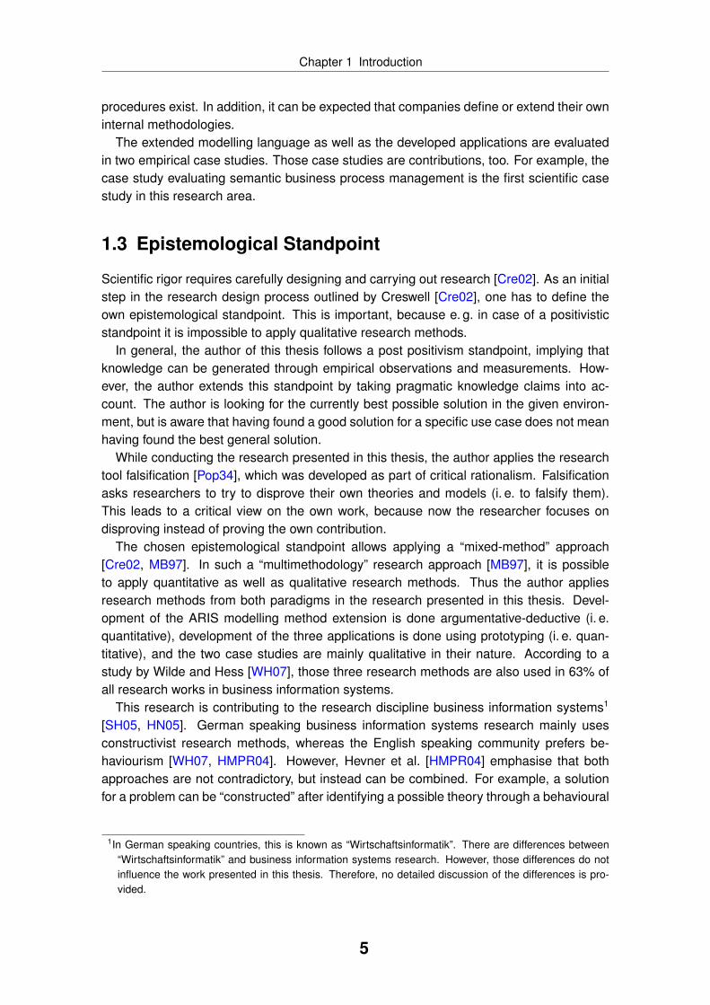
1.3 Epistemological Standpoint
Scientific rigor requires carefully designing and carrying out research [Cre02]. As an initialstep in the research design process outlined by Creswell [Cre02], one has to define theown epistemological standpoint. This is important, because e. g. in case of a positivisticstandpoint it is impossible to apply qualitative research methods.
In general, the author of this thesis follows a post positivism standpoint, implying thatknowledge can be generated through empirical observations and measurements. How-ever, the author extends this standpoint by taking pragmatic knowledge claims into ac-count. The author is looking for the currently best possible solution in the given environ-ment, but is aware that having found a good solution for a specific use case does not meanhaving found the best general solution.
While conducting the research presented in this thesis, the author applies the researchtool falsification [Pop34], which was developed as part of critical rationalism. Falsificationasks researchers to try to disprove their own theories and models (i. e. to falsify them).This leads to a critical view on the own work, because now the researcher focuses ondisproving instead of proving the own contribution.
The chosen epistemological standpoint allows applying a “mixed-method” approach[Cre02, MB97]. In such a “multimethodology” research approach [MB97], it is possibleto apply quantitative as well as qualitative research methods. Thus the author appliesresearch methods from both paradigms in the research presented in this thesis. Devel-opment of the ARIS modelling method extension is done argumentative-deductive (i. e.quantitative), development of the three applications is done using prototyping (i. e. quan-titative), and the two case studies are mainly qualitative in their nature. According to astudy by Wilde and Hess [WH07], those three research methods are also used in 63% ofall research works in business information systems.
This research is contributing to the research discipline business information systems1
[SH05, HN05]. German speaking business information systems research mainly usesconstructivist research methods, whereas the English speaking community prefers be-haviourism [WH07, HMPR04]. However, Hevner et al. [HMPR04] emphasise that bothapproaches are not contradictory, but instead can be combined. For example, a solutionfor a problem can be “constructed” after identifying a possible theory through a behavioural
1In German speaking countries, this is known as “Wirtschaftsinformatik”. There are differences between“Wirtschaftsinformatik” and business information systems research. However, those differences do notinfluence the work presented in this thesis. Therefore, no detailed discussion of the differences is pro-vided.
5
Chapter 1 Introduction
study [HMPR04]. This thesis follows the tradition of German speaking business informa-tion systems research. It uses quantitative as well as qualitative research methods toconstruct an extended modelling method. The measures taken to ensure a high validity ofthe research results are discussed in the following section.
1.4 Research Design
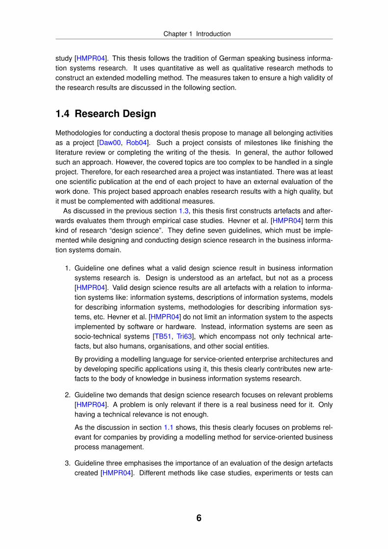
Methodologies for conducting a doctoral thesis propose to manage all belonging activitiesas a project [Daw00, Rob04]. Such a project consists of milestones like finishing theliterature review or completing the writing of the thesis. In general, the author followedsuch an approach. However, the covered topics are too complex to be handled in a singleproject. Therefore, for each researched area a project was instantiated. There was at leastone scientific publication at the end of each project to have an external evaluation of thework done. This project based approach enables research results with a high quality, butit must be complemented with additional measures.
As discussed in the previous section 1.3, this thesis first constructs artefacts and after-wards evaluates them through empirical case studies. Hevner et al. [HMPR04] term thiskind of research “design science”. They define seven guidelines, which must be imple-mented while designing and conducting design science research in the business informa-tion systems domain.
1. Guideline one defines what a valid design science result in business informationsystems research is. Design is understood as an artefact, but not as a process[HMPR04]. Valid design science results are all artefacts with a relation to informa-tion systems like: information systems, descriptions of information systems, modelsfor describing information systems, methodologies for describing information sys-tems, etc. Hevner et al. [HMPR04] do not limit an information system to the aspectsimplemented by software or hardware. Instead, information systems are seen associo-technical systems [TB51, Tri63], which encompass not only technical arte-facts, but also humans, organisations, and other social entities.
By providing a modelling language for service-oriented enterprise architectures andby developing specific applications using it, this thesis clearly contributes new arte-facts to the body of knowledge in business information systems research.
2. Guideline two demands that design science research focuses on relevant problems[HMPR04]. A problem is only relevant if there is a real business need for it. Onlyhaving a technical relevance is not enough.
As the discussion in section 1.1 shows, this thesis clearly focuses on problems rel-evant for companies by providing a modelling method for service-oriented businessprocess management.
3. Guideline three emphasises the importance of an evaluation of the design artefactscreated [HMPR04]. Different methods like case studies, experiments or tests can
6

Chapter 1 Introduction
be applied for evaluation. Hevner et al. demand to follow well established evaluationmethods.
The artefacts created in this thesis are evaluated manifold. For example, the mod-elling language created is challenged in modelling workshops with experts. Empiri-cal case studies are conducted as well following Yin’s [Yin03] methodology for casestudy research. In addition, several scientific publications were prepared to alsohave an external review of the research results.
4. Guideline four demands a clearly recognisable contribution to the body of knowl-edge in business information systems research [HMPR04]. Such a contribution canbe either about an artefact, about the process to develop an artefact or about theevaluation of artefacts.
The work presented in this thesis and summarised in section 1.2 belongs to thefirst category of contribution - knowledge about an artefact. Even though knowledgeabout creating artefacts and evaluating them was also gathered, this is not consid-ered as an own contribution and is therefore not explicitly discussed in this thesis.
5. Guideline five defines that accepted research methods must be applied while con-ducting design science [HMPR04]. It applies to the construction of artefacts as wellas to the evaluation of the created artefacts.
This thesis applies accepted research methods such as argumentative-deductivemethod development, prototyping, and case study research (see also section 1.3).By using case study research, the artefacts created are evaluated in a real-worldsetting.
6. Guideline six characterises design science in business information systems re-search as a search process [HMPR04]. Artefacts are created and optimised inseveral iterations. This search process aims at solutions fulfilling all current require-ments. The found solution does not have to be the final and optimal solution. Ifrequirements change, the artefacts must be changed in a new development cycle.
The development of the artefacts contributed in this thesis followed such an iterativesearch process. For example, the modelling language was discussed with usersseveral times in order to gather their feedback and improve the modelling languageaccordingly. It can be expected that the artefacts presented in this thesis are notfinal, but that they must be changed if new requirements emerge.
7. Finally, guideline seven demands that the research results get published [HMPR04].Yin [Yin03] defines a similar guideline for research results gathered through casestudies. Hevner et al. [HMPR04] emphasise that the solution must be communicatedto a technical audience like engineers and researchers as well as to a businessoriented audience like business experts and managers.
To implement this guideline, the different results were published. This led to an earlyexternal evaluation of the research conducted. The feedback gathered could beincorporated in the research, which helped to improve the research results further.
7

Chapter 1 Introduction
Table 1.1: Publications categorised by media typeMedia Type Number Publications
Journal, conference, workshop(with peer review)
16 [SLEK09], [SLI08a], [SSEKR08],[EKAdMSvdA08], [EKSP08], [SKD+08],[SKI08], [SSEK08b], [FKS08],[EKSMP08a], [EKSMP08b], [SSEK08a],[FFS08], [SBEK07], [DSSK07], [SI07a]
Book chapter/book 5 [SDS+09], [SSEKR09], [SS08b], [SI07c],[SI07b]
Technical report (without peerreview)
14 [FS09], [SH09], [SLI08b], [CSR08],[EKS08], [KSI08], [SKSD08], [Ste08c],[SKW06b], [SKW06a], [Ste06], [SI07d],[SR08], [Ste08b]
Tutorial 8 [FBS+08], [Ste08d], [Ste08a], [Ste07a],[DFK+07], [NS07], [PSS07], [Ste07b]
Sum 43
To reach the technical as well as business oriented audiences, different media typeswere used. The technical audience was reached by publications in journals and atscientific conference and workshops. Those publications were only accepted after ascientific peer review. Potential users and business experts were addressed by pub-lications in books, technical reports, articles in magazines, and tutorials. Table 1.1categorises the different publications based on the media type used.
Following those seven guidelines for design science in the business information systemsresearch ensures that the results presented in this thesis are valid, reliable, relevant, andfollow scientific standards.
1.5 Outline
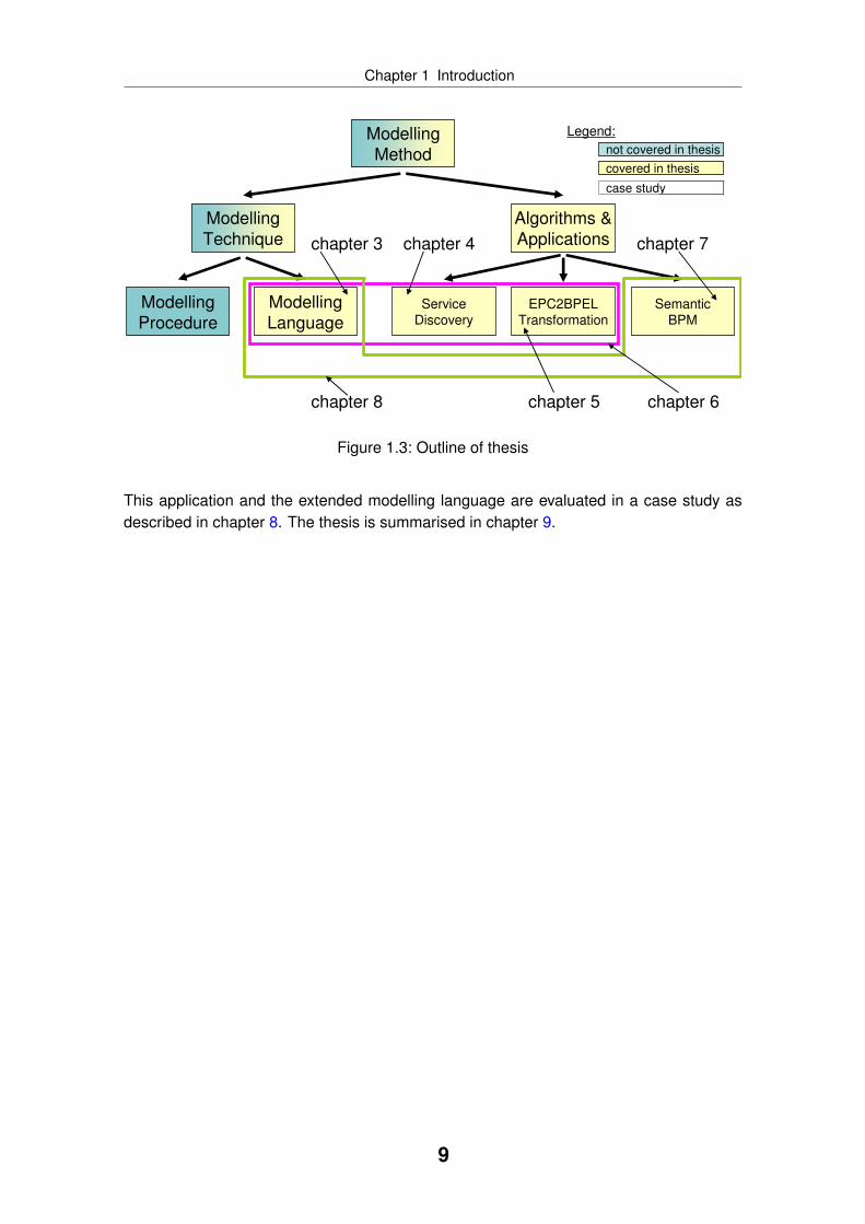
This thesis is structured according to the scientific contributions described in section 1.2.The outline is visualised in figure 1.3. The following chapter 2 describes the current state ofthe art in business process management, service-oriented architecture, business processtransformation, service discovery, and semantic business process management. Chap-ter 3 describes the extended modelling language including the underlying meta model. Af-terwards, the service discovery application is described in chapter 4. The transformation ofservice-oriented business process models into a BPEL service orchestration is describedin chapter 5. The application service discovery and EPC to BPEL transformation as wellas the extended modelling language are evaluated in a case study described in chapter 6.Afterwards, chapter 7 describes the application semantic business process management.
8
Chapter 1 Introduction
Algorithms &
Applications
Modelling
Method
Modelling
Technique
Modelling
Procedure
Modelling
LanguageService
DiscoveryEPC2BPEL
TransformationSemantic
BPM
Legend:
not covered in thesis
covered in thesis
chapter 3 chapter 4
chapter 5 chapter 6
chapter 7
chapter 8
case study
Figure 1.3: Outline of thesis
This application and the extended modelling language are evaluated in a case study asdescribed in chapter 8. The thesis is summarised in chapter 9.
9

Chapter
2 State of the Art
This thesis is based on existing research. This chapter introduces this existing knowledgethrough a state of the art discussion. The chapter is structured according to the differentareas addressed by this thesis. First, business process management is introduced insection 2.1. As this thesis is concerned with integrating the concept of service-orientedarchitecture (SOA) with business process management, section 2.2 provides an overviewof relevant works on SOA. Such an integration can be achieved through model-drivenengineering. Relevant techniques are discussed in section 2.3. One main contribution isan automated transformation to turn business processes into executable ones. Relatedwork on process transformations is presented in section 2.4. Section 2.5 introduces thedifferent approaches to web service discovery. Finally, section 2.6 describes the state ofthe art in semantic business process management.
2.1 Business Process Management
2.1.1 Overview
Different definitions and perceptions of business process management exist. Schmelzerand Sesselmann e. g. characterise business process management as an holistic manage-ment concept to design, control, and optimise business processes [SS08a, p. 5]. Accord-ing to this definition, business process management comprises many other managementmethods like quality management, activity based costing, change management, six sigma,and balanced scorecards [SS08a, pp. 12]. Here, business processes are a means to im-plement a corporate strategy. Similar holistic definitions of business process managementcan be found in [BKR05, SF03]. Besides those works, other authors like [Wes07] viewbusiness process management mainly as a discipline focusing on the automation of busi-ness processes using IT. Those two views of business process management are confirmedby Scheer et al. [SKJK06] by dividing the area into IT focused business process manage-ment on one hand and business oriented business process management on the other
10
Chapter 2 State of the Art
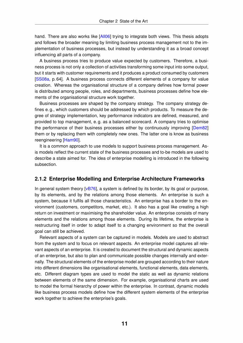
hand. There are also works like [All06] trying to integrate both views. This thesis adoptsand follows the broader meaning by limiting business process management not to the im-plementation of business processes, but instead by understanding it as a broad conceptinfluencing all parts of a company.
A business process tries to produce value expected by customers. Therefore, a busi-ness process is not only a collection of activities transforming some input into some output,but it starts with customer requirements and it produces a product consumed by customers[SS08a, p. 64]. A business process connects different elements of a company for valuecreation. Whereas the organisational structure of a company defines how formal poweris distributed among people, roles, and departments, business processes define how ele-ments of the organisational structure work together.
Business processes are shaped by the company strategy. The company strategy de-fines e. g., which customers should be addressed by which products. To measure the de-gree of strategy implementation, key performance indicators are defined, measured, andprovided to top management, e. g. as a balanced scorecard. A company tries to optimisethe performance of their business processes either by continuously improving [Dem82]them or by replacing them with completely new ones. The latter one is know as businessreengineering [Ham90].
It is a common approach to use models to support business process management. As-is models reflect the current state of the business processes and to-be models are used todescribe a state aimed for. The idea of enterprise modelling is introduced in the followingsubsection.
2.1.2 Enterprise Modelling and Enterprise Architecture Frameworks
In general system theory [vB76], a system is defined by its border, by its goal or purpose,by its elements, and by the relations among those elements. An enterprise is such asystem, because it fulfils all those characteristics. An enterprise has a border to the en-vironment (customers, competitors, market, etc.). It also has a goal like creating a highreturn on investment or maximising the shareholder value. An enterprise consists of manyelements and the relations among those elements. During its lifetime, the enterprise isrestructuring itself in order to adapt itself to a changing environment so that the overallgoal can still be achieved.
Relevant aspects of a system can be captured in models. Models are used to abstractfrom the system and to focus on relevant aspects. An enterprise model captures all rele-vant aspects of an enterprise. It is created to document the structural and dynamic aspectsof an enterprise, but also to plan and communicate possible changes internally and exter-nally. The structural elements of the enterprise model are grouped according to their natureinto different dimensions like organisational elements, functional elements, data elements,etc. Different diagram types are used to model the static as well as dynamic relationsbetween elements of the same dimension. For example, organisational charts are usedto model the formal hierarchy of power within the enterprise. In contrast, dynamic modelslike business process models define how the different system elements of the enterprisework together to achieve the enterprise’s goals.
11

Chapter 2 State of the Art
Table 2.1: Zachman frameworkAbstraction Level What How Where Who When Why
Scope Strategists
Business Executive Leaders
System Architects
Technology Engineers
Component Technicians
Operations Workers
The enterprise model is usually structured according to an enterprise architectureframework like Zachman1, ArchiMate [ARC04, ARC06], MODAF [MOD07], TOGAF[TOG07] or ARIS [Sch02, STA05]. Such an enterprise architecture framework defines thedimensions, abstraction levels, possible element types, and relation types. Table 2.1 showsthe Zachman framework. According to the Zachman framework, an enterprise model mustbe structured into six levels of abstraction and six different dimensions. Each level of ab-straction defines which role will create and work with the content on the abstraction level.In addition, the Zachman framework specifies several rules like that it is forbidden to addnew rows or columns to the framework. Even though the Zachman framework definesthe overall architecture of an enterprise model, it does not specify which notation to usefor the different models. For example, one can freely choose between different businessprocess notations like BPMN or EPC (see subsection 2.1.4) to document the content re-quired in the “How” dimension on the “Business” abstraction level. This thesis is based onthe modelling method ARIS, which includes an enterprise architecture framework amongother things. ARIS is described in the following section.
2.1.3 Modelling Method ARIS
ARIS [Sch02, STA05] is a modelling method developed and maintained by IDS Scheer2.It is according to market research reports by Gartner [Ble07] and Forrester [Pey07] theleading framework in this market. It implements all elements of a modelling method as de-fined by Karagiannis and Kühn [KK02] (see also figure 1.1). Tools for creating, analysing,and communicating models using ARIS are released by IDS Scheer as commercial soft-ware packages under the brand “ARIS Platform”3. The software tools are grouped into sixsolutions addressing different topics like enterprise architecture management and SOA.The modelling procedure is called ARIS Value Engineering (AVE)4. AVE has six differentflavours, one for each solution. However, all AVEs share a common core. ARIS supportsvarious modelling languages like BPMN, EPC, Entity Relationship Model (ERM), organisa-
1http://www.zifa.com/ and http://www.zachmaninternational.com/2http://www.ids-scheer.com/3http://www.aris.com/4http://www.aris.com/ave
12

Chapter 2 State of the Art
Figure 2.1: Dimensions and abstraction levels defined by ARIS
tional charts, product portfolios, balanced scorecards, UML, etc. for modelling all aspectsof an enterprise model. In many cases, a user is free to choose between different alterna-tives like either using BPMN or EPC for business process modelling.
ARIS distinguishes five dimensions each having three abstraction levels as shown in fig-ure 2.1. The process dimension in the centre of the figure links the elements of the otherdimensions together. For example, a process like a business process consists of functionsfrom the functional dimension, which are executed either by organisational elements fromthe organisational dimension or by IT systems from the functional dimension. Each func-tion of the business process consumes and produces data elements defined in the datadimension. A business process also produces products, which are defined in the productdimension.
The ARIS meta model [STA05] is flexible enough to represent those different modellinglanguages and to integrate them. The ARIS meta model predefines a set of object types,connection types, model types (diagram types), and symbol types5. Examples for an ob-ject type are the “organisational unit” object type, the “UML interface” object type or the“(business) function” object type. Symbol types are used to describe subtypes of objecttypes. For example, a function has the subtype “system function”, which is an automatedfunction. Different object types are connected with each other through connection types(i. e. relations). For example, a function and an organisational unit can be connected witheach other using the “carries out” connection type, meaning that the organisational unitexecutes the function. Model types define diagrams like “organisational chart” or “UMLuse-case diagram”. The ARIS meta model specifies, which object types can be related to
5There are more artefacts like attribute groups, but the overall principle remains.
13

Chapter 2 State of the Art
each other using which connection type. In addition, it specifies which object types andconnection types can be used in which model type. A user instantiates the pre-definedobject, model, and connection types like creating an organisational unit named “sales de-partment” in an organisational chart model type.
The object types can be reused between the various models. For example, a specificinstance of an “organisational unit” object type can be used in an organisational chart aswell as in a business process model. Model instances can be linked to object instances.For example, in a business process model a “function allocation diagram” can be assignedto a function to describe the function in more detail. A common application of ARIS isusing it for business process modelling. Business process modelling is described in thefollowing subsection.
2.1.4 Business Process Modelling
Business processes are captured visually to document and communicate them using amodelling language. There are different graphical modelling languages available like EPC[KNS92, STA05], BPMN [OMG06], and UML activity diagrams [OWS+03] to name a few.In addition, products like workflow environments often provide their own specific modellinglanguage.
The EPC modelling language as originally described by Keller et al. [KNS92] is a di-rected graph consisting of arcs and nodes. Arcs connect nodes to define the control flowof the process. Nodes are either functions (i. e. activities), events (i. e. pre- and post-conditions) or operators. An event with no incoming arc is called a start event, an eventwith no outgoing arc is a called an end event. Events and functions alternate. Two consec-utive functions are not allowed. Each function and event has maximum only one incomingand outgoing arc. Exceptions from this rule are operators. They might have either severalincoming or several outgoing arcs. Operators can be either “OR”, “AND” or “XOR”.
The original EPC modelling language has limited applicability, because it only uses el-ements from the functional and process dimension of the enterprise model. For example,it is impossible to specify who is executing a function and which input and outputs areneeded. Therefore, the EPC modelling language used in ARIS today (shown in figure 2.2)is an extended version including elements from other dimensions of the enterprise model.For example, it is possible to relate organisational elements to a function to specify who isexecuting a function. Also, elements representing IT systems can be added for the samepurpose. Functions can be related to different kinds of data elements to model the dataconsumed and the data produced by a function. It is also possible to model the productscreated by the process. There are many additional relations to other elements, which areneeded outside of pure process modelling. For example, for controlling purposes, func-tions can be related to KPI instances to define concrete metrics. Also, all elements have avariety of attributes like those needed for process simulation.
Following the classification by Mendling et al. [MLZ06], the EPC modelling languagehas a graph-structured representation scheme, i. e. the control flow is specified by arcsrepresenting the execution logic between nodes. Still, it is possible to model differentworkflow patterns [vdAtHKB03] like sequence, concurrency, alternatives, and loops which
14

Chapter 2 State of the Art
Function
Event
Event
SYS
Function
Function
Event
Event
Cluster (Data)
is input for
Cluster (Data) has output of
ApplicationSystem Type
Riskoccurs at
Org. Unit
AND
Product
carries out
produces
supports
Figure 2.2: Current EPC notation used in ARIS software tools
can be found in block-oriented modelling languages. However, it is impossible to representall workflow patterns as Mendling et al. [MNN05] show.
Currently, there are two exchange formats for EPC models available. The ARIS soft-ware tools support the proprietary AML format, which also includes diagram information.EPML [MN06] is an alternative exchange format, which is used by many OpenSource EPCmodelling tools. A transformation from AML to EPML exists as well [MN04].
The EPC modelling language is criticised, because of its unclear semantics [Weh07].There are different suggestions to overcome this issue like informal semantics [NR02],local semantics (e. g. free choice semantics [vdA99], boolean semantics [Weh07]), andnon-local semantics [Kin06]. Despite those problems, EPCs are used in many real-worldprojects and the EPC modelling language is also used to document the SAP referenceprocesses.
15
Chapter 2 State of the Art
Similar observations about unclear semantics can be made for BPMN and UML activitydiagrams [KHSW05]. Still, there is a growing popularity of BPMN despite those problems.It is expected that BPMN 26 provides a better definition of the execution semantics. TheBPMN modelling language [OMG06] mainly focuses on the functional and process dimen-sion of the enterprise model, but it is possible to relate elements from other dimensionsto BPMN elements as well. Similar to EPC, BPMN is a structured graph consisting offlow objects, connecting objects, swimlanes, and artefacts. Flow objects are events, activ-ities, and gateways. Possible connecting objects are sequence flows, message flows, andassociations. Swimlanes consist of pools, which may contain lanes. Artefacts are dataobjects, groups, and annotations. Besides those elements, BPMN provides a variety ofattributes, which have no visual representation. Business process models like BPMN andEPC are often the base for business process automation. This is discussed in the followingsubsection.
2.1.5 Business Process Automation
Even though the usage of IT in companies might not create a competitive advantage any-more [Car04], having no IT support at all will not work for most companies. Therefore,companies try to automate or support their business processes using IT. This can be doneeither by introducing standard software and customising it or by creating IT applicationsspecific for the business processes. According to Leymann [Ley04], the combination ofweb services to implement a business need is currently a promising way to create sucha business process specific application. In this scenario, web services are combined byan orchestration language such as BPEL [BPE03, BPE07a, JMS06]. The orchestrationlanguage is executed on an execution engine like Oracle BPEL Process Server or IBMWebsphere.
BPEL is a XML based language to describe an orchestration of web services as a pro-cess. For an overview of web service technology see the next section 2.2. BPEL supportsthe graph-oriented as well as the block-oriented paradigm as defined by Mendling et al.[MLZ06], because its ancestors are XLANG, a block-oriented language, and WSFL, agraph-oriented language [WvdADtH02]. Each element of a BPEL process is an activity,which is either a primitive or a structured one. Primitive activities are invoke, receive, re-ply, assign, throw, wait, terminate, and empty. To construct more complex control flows,structured activities like sequence, while, switch, flow, pick, and scope can be used. BPELallows nesting those structured activities. In addition, links can be used to define pro-cesses in a graph-oriented manner. Links can be also used to influence the executionorder of parallel activities. Besides the different activities, BPEL also provides elements forcompensation handling and exception handling.
BPEL allows the usage of elements from the process, function, and data dimension.The organisational dimension is not addressed by BPEL directly. For example, it is notpossible to specify a human activity. However, with BPEL4People [BPE07b] a standardisedextension exists for this as well.
6The author of this thesis participates in the BPMN 2 standardisation effort at OMG (http://www.omg.org/).
16

Chapter 2 State of the Art
Even though BPEL can be used to automate business processes, it is not meant to beused by business experts for business process modelling. Instead, it is a language meantto be compiled and executed. Therefore, it is necessary to derive a BPEL description froma business process model. This can be done either automatically through model transfor-mation as discussed in section 2.4 or manually as e. g. described by Allweyer [All06, All08].
The refinement of a business process into an executable one is hindered by the socalled business-IT divide [SF03, DvdA04, KHSW05]. The knowledge and backgroundof business experts and IT experts is different and therefore a seamless communicationbetween both groups is not always possible. For example, business experts might usea different terminology than IT experts. Also, a business expert designs a process froma business perspective trying to optimise the way the business is executed. In contrast,an IT expert designs a process from an implementation perspective trying to optimise theexecution on IT systems. Even though both worlds share some concepts, there is alsoinformation needed in only one of the worlds. For example, information for simulating abusiness process is not needed by an IT expert. On the contrary, a business expert is notinterested in exception and transaction handling.
Different strategies exist trying to overcome the business-IT divide. Smith and Fingar[SF03] try to obliterate the business-IT divide. Instead of transforming the business pro-cess model into an executable one, the business process model is directly executed. Sofar, this vision of obliterating the business-IT divide is not achieved. Another approachis using semantic technologies like reasoners, ontologies, and semantic web services.This approach is known as semantic business process management and is described insection 2.6. Besides manual approaches like [All06, All08], many authors suggest usingautomated model transformations to derive an executable process model out of a busi-ness process model. The state of the art on model transformations for business processautomation is presented in section 2.4. Many of the approaches discussed in section 2.4apply the concept of service-oriented architecture (SOA), which is introduced in the follow-ing section.
2.2 Service-Oriented Architecture
2.2.1 Overview
The concept of service-oriented architecture (SOA) is a hot topic discussed in research aswell as in industry. Most discussions focus on using SOA as a technological concept fordesigning an IT infrastructure. This view on SOA is discussed in the following subsection.There are other publications about a broader more abstract view of SOA. Here, SOA isperceived as a management concept shaping the overall structure of an enterprise. Thisunderstanding of SOA is discussed in subsection 2.2.3.
2.2.2 Technological SOA
In one of the first publications on SOA [SN96], SOA is described as an IT architecture.Common business logic and data input/output functionality is moved into services so that
17

Chapter 2 State of the Art
it can be shared between different applications. A service is mainly seen as a componentproviding access to a data store like a database. It is the idea to make the access to datatransparent by hiding the way data is distributed among different databases. In contrastto ordinary software architecture, the service is not part of one application’s architecture,but it is outside of the different applications using it. The authors [SN96] do not give anydetails how a service should be implemented or which technologies should be used toimplement the interaction between service and service consumers (i. e. the applicationsusing the shared functionality).
This view on SOA is supported by service-oriented computing [PG03]. Services areseen as “self-describing, open components that support rapid, low-cost composition ofdistributed applications” [PG03, p. 26]. However, in contrast to the previous work on SOA[SN96], services are said to communicate over the Internet, which is leading to the term“web service”. This documents a step away from using the service concept for softwarearchitecture as it was done in component oriented software design [Szy97, HS00]. Eventhough Papazoglou and Georgakopoulos [PG03] demand web services, they do not spec-ify which specific communication protocol to use. They only point out that web servicesmust be described and advertised, but they do not define which technologies to use. Asimilar definition of web services can be found in [Kre01]. Here, web services are “a col-lection of operations that are network-accessible through standardized XML messaging”[Kre01, p. 6].
Today, SOA standard literature [KBS05, Erl05, MSJL06] introduces web services asa technology based on the so called “W3C stack”. The term W3C stack refers to a setof standards published by the World Wide Web Consortium (W3C) like WSDL [WSD01],SOAP [GHM+03], HTTP [FGM+99], and the many different web service security standards(see [MSJL06] for an overview). WSDL [WSD01] is a XML based language describing theinterface of a web service. Operations with their parameters can be defined and groupedinto interfaces (which are called porttypes in WSDL version 1.1). Furthermore, bindingscan be defined specifying by which transport mechanism the operations of a porttypecan be accessed. Messages send between service consumer and service provider areencapsulated using SOAP [GHM+03]. SOAP messages are transported by a transportmechanism like HTTP [FGM+99], SMTP or FTP.
In order to allow potential service consumers to find a web service, the web servicedescription (i. e. WSDL) is published in a service registry by the service provider as shownin figure 2.3 [Kre01]. The service consumer retrieves the web service description and bindsthe web service. The message exchange between service consumer and service provideris based on SOAP messages, which are transported with protocols like HTTP. There aredifferent efforts for providing a web service registry standard like UDDI [CHvRR04] orebXML [FNS05]. Even though the W3C stack is adopted in industry, web service registrieshave not seen the same adoption rate.
Web service orchestration languages like BPEL [BPE03, BPE07a, JMS06] and XPDL[XPD08] combine several web services based on a process definition. This executableprocess definition itself is a web service, which can be invoked by another web serviceorchestration. This allows building a recursive hierarchy of web services. In complex ITenvironments, the BPEL execution engine does not directly invoke the web services as
18

Chapter 2 State of the Art
Service
Registry
Service
Requestor
Service
Provider
WSDL WSDL
bind & interact
UDDIebXML
Figure 2.3: SOA pyramid [Kre01]
specified by the BPEL process, but forwards each invocation request to an ESB software.Among other things, an ESB software supports load balancing so that execution of a webservice can be spread over several machines. The use of ESB software allows introducingcloud computing [Ley08], because the computation resources are not visible anymore tothe consumer.
Different authors [HHV06, ST07, KBS05, Erl05, MSJL06] provide collections of bestpractices supporting the design of reusable web services. There are also specific softwaredevelopment processes and methodologies available for web service development (seee. g. [PvdH06]).
Even though there seems to be a wide adoption of the W3C stack in enterprise comput-ing, some authors point to the fact that using the W3C stack is one possible way to imple-ment a SOA. Recently, the concept of using standard Internet protocols like HTTP withoutadding new layers like SOAP and WSDL on top of it received some traction [Alg07, Vin08].This approach is known as REST [Fie00]. At the current point, it is unclear if the W3Cstack will be adopted all over industry or if alternative concepts like REST will succeed.However, this shows that a SOA must be designed in a way to be as independent of anyspecific technology as possible, so that the implementation technology can be changed ifnew products and technologies become available. Besides discussing the specific tech-nology to base a SOA on, there are also broader and more abstract definitions of SOA asdiscussed in the following subsection.
2.2.3 Service-Orientation as Management Concept
There is some confusion about SOA, because SOA is often mixed with service science,even though both topics are not directly related. Service science [Teb06] deals with de-signing products, which are offered as service. Such services have some unique featurescompared to ordinary manufactured products like that a closer customer interaction isneeded while delivering the service. For example, in a consulting engagement the cus-tomer is working together with the contractor to come up with a possible solution. Accord-ing to Teboul [Teb06], today every product sold also contains to some degree a service. In
19

Chapter 2 State of the Art
his view, service is “front-stage” meaning it is the visible part of the customer interaction,whereas the product is “back-stage” and its preparation is not directly visible to the cus-tomer. Even though such a view on service can be adopted in SOA as well, it is not theprimary concern of service science. Service science focuses on different topics like how acustomer interaction must be designed to have a satisfying service experience. Therefore,service science literature is not further investigated, because it does not directly contributeto the topic of this thesis.
Extensive work on SOA is available as the OASIS SOA Reference Model [MLM+06].The SOA Reference Model defines the main terms used in this context like service, ser-vice consumer, service provider, service description, service interface, etc. It defines SOAas “a paradigm for organizing and utilizing distributed capabilities” [MLM+06, p. 8]. Ac-cording to this definition, services are “the mechanism by which needs and capabilities arebrought together” [MLM+06, p. 9]. A service must have the capability to perform work forsomeone with a need, it must specify, which work it can perform for others, and it mustoffer to actually do the work if requested [MLM+06]. Therefore, a service needs “visibility”to be used. Visibility consists of “awareness”, “willingness”, and “reachability” [MLM+06].Awareness means that service consumer and service provider must be aware of eachother. Willingness refers to the fact that both parties intent to work together. Finally, reach-ability means that service consumer and service provider can communicate. If one of thethree components is missing, no interaction is possible. For example, if both parties arewilling to work together and if they are both reachable, but if they do not know of eachother (i. e. no awareness), an interaction is impossible. The SOA Reference Model definesadditional terms like real world effects, contract and policy, and execution context. Themodel can be used to standardise the terminology used in a SOA project. It also helpsto visualise different conceptions of SOA, e. g. if SOA is solely seen as a technologicalconcept. The SOA Reference Model is independent of any technology. In fact, it does noteven demand an IT implementation of services.
Several researchers and standardisation bodies are working on different parts of a SOAmodelling method. For example, there are various efforts trying to define the semanticsof such a modelling language by creating SOA meta models. CBDI Service Architectureand Engineering (CBDI-SAE) [CBD07] is a SOA meta model including a taxonomy of allterms used. According to [CBD07], CBDI-SAE was made available to OMG for public stan-dardisation. Even though CBDI-SAE provides concepts for describing a business-orientedSOA independent of technology, it still focuses on services implemented as software. Forexample, it provides detailed models to describe the deployment of software services.CBDI-SAE is not integrated with any existing enterprise architecture framework or busi-ness process management modelling method. This makes it hard for potential users toadopt CBDI-SAE, because they first have to integrate it in the framework they use. Also,CBDI-SAE does not provide a modelling language, but focuses on defining a SOA metamodel. Again, potential users have to define their own modelling language in order tocapture the content specified by CBDI-SAE.
Jones and Morris [JM05] propose in their submission paper to OASIS a SOA method-ology. This SOA methodology is a modelling procedure with an implicitly defined mod-elling language. However, an unambiguous definition of the modelling language is missing.
20
Chapter 2 State of the Art
Jones extends this work in [Jon06] giving some examples how such a modelling languagemight look like. The work [JM05, Jon06] focuses on a business architecture. In an initialstep, it captures the main services offered by a company. While building a service archi-tecture, it should be first described what needs to be done, instead of describing how it isachieved. The authors reject the usage of processes on top level of an enterprise modeland instead propose the usage of business services. Only few of them are defined on thetop level. Those business service are further refined. Supporting services are added forcapabilities not directly contributing to the overall business goal, but still needed for opera-tion. Besides the modelling procedure, the work [JM05, Jon06] also provides details howto conduct a SOA project. For example, it defines roles needed in such a project.
Different enterprise architecture frameworks with a strong focus on service orientationexist. The ArchiMate framework [ARC04, ARC06] uses service entities on different ab-straction levels and views within the framework. A service is always connecting the differ-ent abstraction levels. For example, the more generic application layer can use technologyservices provided by the technology layer. However, this approach of a fixed set of servicecategories is not very flexible. The enterprise architecture framework MODAF [MOD07]has a strong notion of defining capabilities. It provides different views to describe capa-bilities and their relationships. ArchiMate and MODAF are missing a graphical modellinglanguage. Potential users have to define their own modelling language.
The ARIS [Sch02, STA05] modelling method for enterprise architecture and businessprocess management provides extensive support for modelling service-oriented IT archi-tectures. An IT system can be described on different abstraction levels using differentmodelling languages like UML. WSDL web services can be modelled in ARIS, too. How-ever, a notion of a service independent of IT is missing in ARIS.
2.3 Model-Driven Integration Engineering
2.3.1 Overview
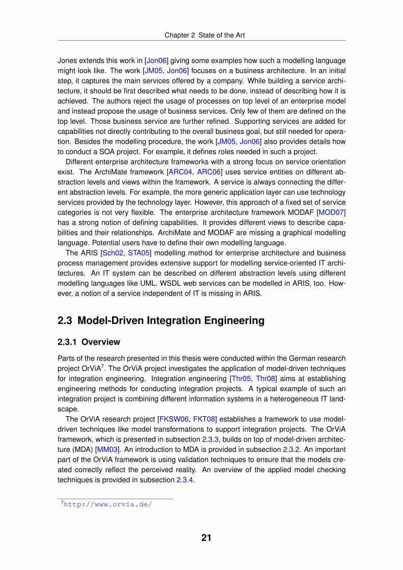
Parts of the research presented in this thesis were conducted within the German researchproject OrViA7. The OrViA project investigates the application of model-driven techniquesfor integration engineering. Integration engineering [Thr05, Thr08] aims at establishingengineering methods for conducting integration projects. A typical example of such anintegration project is combining different information systems in a heterogeneous IT land-scape.
The OrViA research project [FKSW06, FKT08] establishes a framework to use model-driven techniques like model transformations to support integration projects. The OrViAframework, which is presented in subsection 2.3.3, builds on top of model-driven architec-ture (MDA) [MM03]. An introduction to MDA is provided in subsection 2.3.2. An importantpart of the OrViA framework is using validation techniques to ensure that the models cre-ated correctly reflect the perceived reality. An overview of the applied model checkingtechniques is provided in subsection 2.3.4.
7http://www.orvia.de/
21
Chapter 2 State of the Art
2.3.2 Model-Driven Architecture
Model-driven architecture (MDA) [MM03] is a paradigm promoted by OMG. In most cases,MDA is used within model-driven software development. However, MDA is not limited tothis domain, because it focuses on model-driven system development. A system mayinclude “anything: a program, a single computer system, [. . . ], people, an enterprise, afederation of enterprises” [MM03, p. 2]. This is a broad definition, which is similar to theone found in general system theory [vB76]. However, it is admitted that in most cases MDAis used for model-driven software engineering [MM03, p. 2].
MDA introduces three major viewpoints as a mean for abstraction: computation indepen-dent viewpoint, platform independent viewpoint, and platform specific viewpoint. Modelsare used to capture the view on a system from one of the three viewpoints. Consequently,there are three different model levels:
• The computation independent model (CIM) is an outside view on the system not re-vealing any internal details [MM03]. A CIM is used by practitioners, who are dealingwith the system, but who usually do not have the necessary knowledge to under-stand the internal realisation details of the system. Therefore, the CIM is used tobridge the gap between those making use of a system and those implementing it.
• The platform independent model (PIM) describes internal details of a system, butabstracts from a specific platform [MM03]. Therefore, the description provided issuitable for different platforms.
• The platform specific model (PSM) is the most concrete level in MDA [MM03]. Itprovides all details required to execute the system on a specific platform. Therefore,the PSM is not portable, because it makes use of the specific concepts of a platform.
MDA envisions using model transformations to derive a PSM out of a PIM [MM03].Such a transformation uses the information available in the PIM and other informationlike specific transformation rules for a target platform. It is expected that a PIM can betransformed into different PSMs using different transformations. MDA does not define howsuch a transformation is implemented, but it only outlines the overall concepts. Therefore,a transformation does not have to be (completely) automated. This is a main differenceto computer-aided software engineering (CASE), where all parts of a software should begenerated out of models.
MDA is too abstract to be applied directly. For example, MDA does not define whichmodels are needed, which aspects of a system must be described, and how to executea transformation. Therefore, specific frameworks are needed guiding an user in applyingmodel-driven engineering. The OrViA framework, described in the following subsection, issuch a framework.
2.3.3 OrViA Framework
The OrViA framework [KTS05, FKSW06, FKT08] is illustrated in figure 2.4. It can beseen that the OrViA framework uses models on different abstraction levels. The OrViAframework provides a top-down approach to model-driven integration engineering.
22

Chapter 2 State of the Art
transformationorchestration patterns(domain-specific)
cooperativee-business systems
(e.g. Microsoft BizTalk, Intershop Enfinity)
technicalorchestration models
(e.g. BPEL4WS)
business requirements(unstructured, informal)
businessprocess models
(e.g. EPC)XOR
business requirements(structured, formal)
structured requirements analysis
validation
requirements patterns(domain-specific)
Figure 2.4: OrViA framework [KTS05]
At the beginning, only informal and unstructured requirements exist. This tacit knowl-edge is turned into structured and formal models through structured requirements anal-ysis. The OrViA framework does not specify how to perform structured requirementsanalysis. For example, in case of software engineering, requirements engineering tech-niques [KS04] are used. One application area of the OrViA framework is business processautomation (see subsection 2.1.5). Therefore, techniques taken from business processmanagement can be used as well. The OrViA framework envisions that domain specificpatterns are used to facilitate this step. For example, domain specific reference modelscan be used to make models more expressive.
After structured requirements analysis, formal and structured models exist. Those mod-els are viewed as a platform independent description of the integration scenario. TheOrViA framework applies model transformations to those models to turn them into tech-nical platform specific models. For example, in case of business process automation,business process models (e. g. EPC or BPMN models) are transformed into executablemodels like BPEL. This transformation uses platform specific transformation rules. Thegenerated platform specific models are used for execution, which is shown at the bottom offigure 2.4. The transformations for business process automation discussed in section 2.4are a possible implementation of the transformation step within the OrViA framework.
Figure 2.4 shows validation as another main element of the OrViA framework. Valida-tion is used at various places during the integration project. It ensures that the informalrequirements existing at the beginning are correctly implemented at the end of the in-tegration project. For example, besides formalising the requirements, also rules to be
23
Chapter 2 State of the Art
implemented are extracted. The rules are used to check that the platform independentas well as the platform specific models comply to the rules established. Within the OrViAresearch project, a specific technology is used to implement validation. This technology ispresented in the following subsection.
2.3.4 Model Checking
A modelling language consists of syntax, notation, and semantic. Whereas the syntaxspecifies how to use the different elements of the modelling language, the semantic speci-fies the meaning of the different elements. Many works like [KKGL08] exist, which are val-idating the syntax of a given model. Such works are important, because they ensure thatthe modelling language is used correctly. However, syntax validation cannot ensure that amodel is meaningful, because it does not analyses the content of the model. Therefore, theOrViA research project investigates more advanced technologies enabling content valida-tion. Specifically, the OrViA research project investigates techniques for temporal processvalidation. Such a validation approach consists of two main parts:
• models to be validated
• rules, which the models must comply with
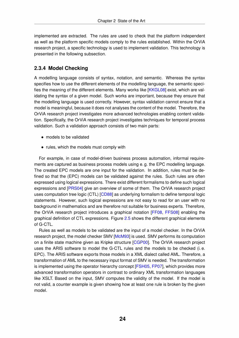
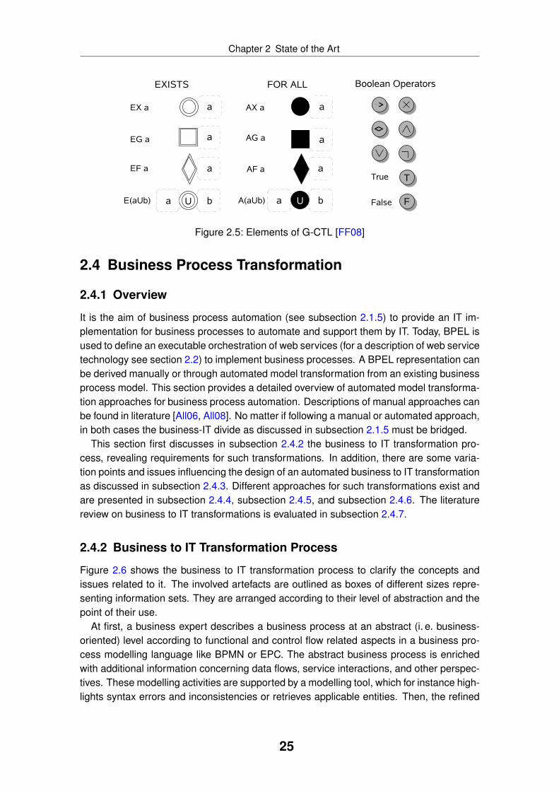
For example, in case of model-driven business process automation, informal require-ments are captured as business process models using e. g. the EPC modelling language.The created EPC models are one input for the validation. In addition, rules must be de-fined so that the (EPC) models can be validated against the rules. Such rules are oftenexpressed using logical expressions. There exist different formalisms to define such logicalexpressions and [PRS04] give an overview of some of them. The OrViA research projectuses computation tree logic (CTL) [CD88] as underlying formalism to define temporal logicstatements. However, such logical expressions are not easy to read for an user with nobackground in mathematics and are therefore not suitable for business experts. Therefore,the OrViA research project introduces a graphical notation [FF08, FFS08] enabling thegraphical definition of CTL expressions. Figure 2.5 shows the different graphical elementsof G-CTL.
Rules as well as models to be validated are the input of a model checker. In the OrViAresearch project, the model checker SMV [McM93] is used. SMV performs its computationon a finite state machine given as Kripke structure [CGP00]. The OrViA research projectuses the ARIS software to model the G-CTL rules and the models to be checked (i. e.EPC). The ARIS software exports those models in a XML dialect called AML. Therefore, atransformation of AML to the necessary input format of SMV is needed. The transformationis implemented using the operator hierarchy concept [FSH05, FP07], which provides moreadvanced transformation operators in contrast to ordinary XML transformation languageslike XSLT. Based on the input, SMV computes the validity of the model. If the model isnot valid, a counter example is given showing how at least one rule is broken by the givenmodel.
24
Chapter 2 State of the Art
Figure 2.5: Elements of G-CTL [FF08]
2.4 Business Process Transformation
2.4.1 Overview
It is the aim of business process automation (see subsection 2.1.5) to provide an IT im-plementation for business processes to automate and support them by IT. Today, BPEL isused to define an executable orchestration of web services (for a description of web servicetechnology see section 2.2) to implement business processes. A BPEL representation canbe derived manually or through automated model transformation from an existing businessprocess model. This section provides a detailed overview of automated model transforma-tion approaches for business process automation. Descriptions of manual approaches canbe found in literature [All06, All08]. No matter if following a manual or automated approach,in both cases the business-IT divide as discussed in subsection 2.1.5 must be bridged.
This section first discusses in subsection 2.4.2 the business to IT transformation pro-cess, revealing requirements for such transformations. In addition, there are some varia-tion points and issues influencing the design of an automated business to IT transformationas discussed in subsection 2.4.3. Different approaches for such transformations exist andare presented in subsection 2.4.4, subsection 2.4.5, and subsection 2.4.6. The literaturereview on business to IT transformations is evaluated in subsection 2.4.7.
2.4.2 Business to IT Transformation Process
Figure 2.6 shows the business to IT transformation process to clarify the concepts andissues related to it. The involved artefacts are outlined as boxes of different sizes repre-senting information sets. They are arranged according to their level of abstraction and thepoint of their use.
At first, a business expert describes a business process at an abstract (i. e. business-oriented) level according to functional and control flow related aspects in a business pro-cess modelling language like BPMN or EPC. The abstract business process is enrichedwith additional information concerning data flows, service interactions, and other perspec-tives. These modelling activities are supported by a modelling tool, which for instance high-lights syntax errors and inconsistencies or retrieves applicable entities. Then, the refined
25

Chapter 2 State of the Art
AbstractBPM Refined
BPM
manualrefine-ment
AbstractOrchestration Refined
Orchestration
manualrefine-ment
RefinedBPM'evolution
Abstract Orchestration
transformation
Refined Orchestrationevo-
lutionsynchronisationlevel of
abstraction
time
transformation
BPM = Business Process Model
Figure 2.6: Artefacts in business to IT transformation process
business process model is translated into an abstract orchestration model (i. e. BPEL). Be-fore executing it, the model is extended by an IT expert adding technology-related aspectssuch as service bindings or exception handling.
The artefacts created evolve over time. The IT expert may change the refined orches-tration. At the same time, the business expert may modify the business process model,because of changing business requirements, incremental development cycles or inappro-priate test results. The changed business process model again is translated in an abstractorchestration model. Since the transformation result conflicts with the evolved refined or-chestration, the models must be synchronised.
2.4.3 Variation Points and Transformation Issues
The outlined transformation process consists of several variation points and issues. A vari-ation point is a case where a decision between rather equivalent alternatives for instanti-ating the transformation process in a specific environment must be taken. For example, atransformation process might either support BPMN or EPC to define the business processmodel. An issue is an inherent difficulty for which no obvious solution exists. For example,transforming a graph-structured process graph into block-oriented BPEL is not possibleunder all circumstances.
Variation Point: Business Process Modelling LanguageThe modelling language defines modelling concepts used to describe certain aspects ofbusiness processes and the level of abstraction at which these aspects are considered.EPC and BPMN provide accepted notations for this purpose as discussed in subsec-tion 2.1.4. BPMN provides more technical-oriented concepts, but is also considered asan adequate notation for business experts. Another relevant notation often used in contextof object-oriented design is UML activity diagrams.
Issue: Complexity Reduction StrategyBusiness processes are manifold entities. An adequate description of them for the pur-pose of transformation introduces a significant cognitive complexity. Different mechanismsmay be used for complexity reduction, e. g. introduction of new language constructs, intro-duction of domain-specific patterns or multi-perspective modelling.
26

Chapter 2 State of the Art
Variation Point: SOA Implementation TechnologyDuring a business process automation project a decision must be taken which implementa-tion technology to use. The solution space ranges from workflow related languages XPDLand web service oriented languages like BPEL to domain-specific execution languagesused in business domains such as e-government and e-commerce. Besides, there aremany proprietary languages offered by different middleware vendors. For more details seesubsection 2.1.5.
Issue: Transformation PowerThe degree of how the divide between business and IT can be bridged through modeltransformations depends on various aspects like: the process perspectives used, the gran-ularity of entities, the tolerated extent of ambiguity, the incompleteness and inconsistencyof input models, the readability of output models, and others.
With respect to granularity and amount of data of input and output models, Mens et al.[MCVG05] distinguish horizontal and vertical transformations. A horizontal transformationtranslates input and output models on the same level of abstraction, whereas a verticaltransformation refines the input model to a more detailed level. In context of business toIT transformations, a horizontal transformation uses a business process model annotatedwith technical details. In case of a vertical transformation, only an orchestration stub iscreated. In both cases, the transformation value is rather limited. Vertical transformationstry to bridge the gap between business and IT by adding additional information, which israther difficult to accomplish and has impacts in synchronisation of co-evolved artefacts.
The semantics of business process modelling languages is often not precisely definedas discussed in subsection 2.1.4 [KHSW05, Weh07]. A transformation approach has tohandle this issue, e. g. by restricting the input language to an unambiguous subset.
Variation Point: Representation SchemeConcerning readability, Mendling et al. [MLZ06] classify process modelling languagesaccording to two different representation schemes. EPC and BPMN are mostly graph-structured, i. e. the control flow is specified by arcs representing the execution logic be-tween nodes (see subsection 2.1.4). In opposite, block-oriented languages define the con-trol flow by nested elements representing sequences, concurrency, alternatives, and loops.BPEL provides concepts for both paradigms in a redundant manner [WvdADtH02]. Conse-quently, transformation approaches between graph-structured business process modellinglanguages and BPEL have a certain freedom of choice.
Issue: Adaptability and Extensibility of the TransformationCustomisation of the execution environment or the modelling language may cause adap-tation or extensions of the transformation as well. Declarative implementations expressedin relational or graph based transformation languages tend to provide more adaptable andunderstandable transformation rules than operational implementations expressed in im-perative transformation languages. Functional and template based approaches may beused for both paradigms.
27

Chapter 2 State of the Art
Issue: Iterative Development SupportThe co-evolution of process models at different levels of abstraction causes divergent arte-facts. As outlined in figure 2.6, conflicting models overlap to some extent. Changed ab-stract orchestration elements resulting from changed business process models have to bemerged with changed elements of the refined orchestration. A comprehensive transfor-mation approach defines mechanisms for model synchronisation, which is also known asreconciliation [KHSW05].
Variation Point: Level of AutomationEven though this section describes work on automated business to IT transformations, thedegree of automation might vary. For example, a transformation approach might requireadditional manual steps before the actual transformation is started. Therefore, there iscertain freedom in choosing a level of automation.
Considering these issues and variation points, existing transformation approaches canbe grouped into two main classes:
1. Approaches focusing on control flow transformation (presented in subsection 2.4.4).
2. Approaches trying to provide more comprehensive support by transforming addi-tional artefacts besides the control flow. This class can be further divided into thefollowing two subclasses:
a) Approaches using domain-specific language extensions (presented in subsec-tion 2.4.5).
b) Approaches using frameworks (presented in subsection 2.4.6).
The literature overview focuses only on works transforming business process models(EPC, BPMN or UML activity diagrams) into the orchestration language BPEL, becauseBPEL has the widest industrial adoption.
2.4.4 Control Flow Centred Approaches
Basic considerations about transformations of business process models into executableones (and vice versa) are described by Hauser and Koehler [HK04]. They use compilertheory techniques to transform process graphs (a subset of UML activity diagrams) intoBPEL. Their approach translates sequential process graphs (without OR-splits and OR-joins) into goto-programs, which are further processed by a goto-elimination algorithm.Concurrent parts are translated by identification of sequential “single entry single exit”(SESE) fragments.
In a similar approach, van der Aalst and Lassen [vdAL05] abstract from concrete mod-elling languages (like EPC, BPMN or UML activity diagrams) and use workflow nets in-stead. Similar to [HK04], they identify and translate structured SESE fragments.
A pragmatic transformation approach from EPC to BPEL is proposed by Ziemann andMendling [ZM05], who restrict their approach to acyclic EPCs. Depending on connecteddata elements, EPC functions are mapped to basic BPEL activities (like invoke, receive orreply). The EPC is translated to graph-structured BPEL constructs on the basis of split and
28

Chapter 2 State of the Art
join patterns. The approach is implemented as XML transformation working on the EPMLformat (for information on EPML see [MN06, MN04]).
Kopp et al. [KUL06] describe a similar approach. The authors map acyclic extendedNautilus EPCs, which allow in contrast to standard EPCs [KNS92] multiple events betweenfunctions, to graph-structured BPEL. EPC events are interpreted as transition conditionsof BPEL links.
In contrast to graph-structured transformations, the approach described by Specht et al.[SDTK05] relies on the identification of workflow patterns [vdAtHKB03] to transform struc-tured EPCs to block-structured BPEL. Inner EPC events are interpreted as business-oriented documentation and are ignored in the transformation process. The algorithmsearches for corresponding split and join patterns and transforms such pairs to BPELswitch and flow activities.
Similar transformation approaches exist for other graph based business process mod-elling languages. White [Whi05] proposes a mapping between BPMN and BPEL on thebase of templates and relations between syntax elements. Yet, this description is consid-ered as informal and incomplete [MLZ06, ODBtH06]. The BPMN specification [OMG06]does not provide significant improvements with respect to this. A more formalised ap-proach is given by Ouyang et al. [ODBtH06]. For each BPMN activity so-called precondi-tion sets are identified, which are mapped to event condition actions in BPEL (onEvent han-dlers). The authors emphasise that their approach can be improved according to compact-ness and comprehensibility aspects. Following this intention, Ouyang et al. [OvdADtH06]combine this approach with a structure-identification mechanism based on components[vdAL05].
2.4.5 Approaches Based on Domain-Specific Language Extensions
Several approaches rely on UML activity diagrams extended by self-defined or standard-ised UML profiles. Mantell [Man03] proposes a BPEL-specific profile to model and trans-form UML activity diagrams. Activities are marked with stereotypes such as «process»,«receive» or «invoke».
Bordbar and Staikopoulos [BS04] use a specific UML profile, too. UML activity diagramsmodelled by business experts are refined and enriched with stereotypes such as «CallOp-erationAction» or «datastore». The enriched process models are transformed to BPEL forwhich the authors outline a few transformation rules.
Skogan et al. [SGS04] take existing web services in terms of WSDL descriptions into ac-count. WSDL descriptions are transformed to UML class diagrams, which are referencedby UML activity diagrams. The transformation to BPEL relies on technical information inthe business process model. For example, activities are stereotyped with «WebService-Call» or «DataTransformation».
Heckel and Voigt [HV04] define a BPEL-specific UML profile for UML component, class,and activity diagrams. They call for synchronism between the UML source and the BPELtarget, which allows iterative incremental development. For this purpose, a declarativetransformation approach using graph transformation techniques is proposed.
Another BPEL generation approach is given by Yu et al. [YZZ+07]. This approach differs
29

Chapter 2 State of the Art
from other UML profile based approaches by relying on a standard UML profile (EDOCCCA8) and using OMG’s standard transformation technique QVT.
Following the intention of EPC transformation approaches like [ZM05, KUL06, SDTK05],Schmelzle [Sch07] transforms acyclic EPCs to graph-structured BPEL processes. He ex-plicitly differentiates between business oriented and implementation oriented levels of ab-stractions. The author declines using default values for aspects not expressed in the busi-ness process models but required on the implementation level. Instead, an intermediatelevel is introduced, where additional information can be supplemented using annotations.
2.4.6 Approaches Based on Frameworks
Another class of approaches proposes extensible frameworks, which have to be adapted tothe specific requirements of an application domain. Allweyer [All07] applies model-drivenarchitecture (MDA) [MM03] concepts to the area of business process management andoutlines an EPC framework based on high-level process patterns. The conceptual frame-work requires the specification of validation rules for source models, templates for targetmodels, and transformation rules defining the execution logic of templates. The proposedapproach should be applicable for recurring business related as well as implementation re-lated problems. The outlined approach is presented as a control flow centred non-iterativeone-step refinement, whereas extensions according to a multi-perspective and multi-stepapproach are possible.
Considering multi language support as an essential feature in design and implementa-tion phases of process-driven SOAs, Zdun and Dustdar [ZD06] propose a language engi-neering framework based on model-driven development concepts. The framework allowsthe recursive specification of modelling patterns based on pattern primitives. For example,to decompose the control flow perspective the concepts “Macroflow”, “Macroflowsteps”,“Microflow”, and “Microflowsteps” are introduced. The authors refer to code generationcapabilities of the framework but without any detailed explanation.
Instead of a pattern based approach, Roser et al. [RLB07] propose a language ori-ented framework. It allows the extension of standard workflow models with pre-defineddomain concepts, such as “application”, “service” or “offer”. Additionally, to support dif-ferent expectations, experiences, and skills of business experts and IT experts, languageconcepts can be visualised differently using customised concrete syntaxes. For the pur-pose of adaptability and reuse, the framework aims at the separation of domain specificand domain independent concerns. It is therefore structured into domain specific languageadapters and code generation templates and domain independent process transformationand rephrasing components.
2.4.7 Evaluation
The variation points and issues discussed in subsection 2.4.3 are used to evaluate thetransformation approaches. Because of the different intentions, control flow centred andholistic approaches are discussed separately.
8http://www.omg.org/technology/documents/formal/edoc.htm
30

Chapter 2 State of the Art
Table 2.2: Control flow centred transformation approachesHT/VT = Horizontal/Verticaltrans., EP/EM = ElementPreservation/ Minimisation,SI/SM = StructureIdentification/Maximisation
Input/Output Abstr. Strategy Paradigm Descr.
Source Target HT
VT
EP
EM
SI
SM
Impe
rativ
eFu
nctio
nal
Rel
atio
nal
Gra
phTe
mpl
ate
Form
al
Sem
if.
[ZM05] EPK BPEL × × × ×[ODBtH06] BPMN BPEL × × × ×[KUL06] N-eEPK BPEL × × × ×[SDTK05] EPK BPEL × × × ×[Whi05] BPMN BPEL × × × × ×[HK04] UML AD BPEL × × × ×[vdAL05] WFN BPEL × × × ×[OvdADtH06] BPMN BPEL × × × × ×
Control flow centred transformation approaches focus on the process perspective, whichaccording to [KtHvdA03] is the most essential dimension of process modelling languagesand engines. The mapping of the functional perspective is basically restricted to speciali-sation refinements. Abstract concepts (e. g. EPC functions) are replaced by more concreteconcepts with reduced extension and increased intension (e. g. BPEL receive, reply, invokeactivities). Other refinement strategies (see [CE00, GS04]) like functional or aspectual de-composition, choice of representation, choice of algorithm, concretisation, elaboration, andrealisation are only partly used. Therefore, these approaches are horizontal transforma-tions (see table 2.2).
Control flow centred approaches deal with different process representation schemes(graph-oriented, block-oriented) and can therefore be classified according to the fourtransformation strategies for business process models described in [MLZ06]: “Element-Preservation” (EP), “Element-Minimisation” (EM), “Structure-Identification” (SI), and“Structure-Maximisation” (SM). Since most approaches are formally described, the un-derlying programming paradigm used to implement the approach can be determined.The spectrum ranges from imperative and functional implementations to relational, graphbased, and template based approaches [MCVG05]. The evaluation for control flow centredapproaches is shown in table 2.2.
Table 2.3 summarises domain specific and framework based approaches. Most of themextend control flow centred process transformations to holistic approaches in terms of us-ability and code generation capabilities. The described UML based transformations usethe UML language extension mechanisms to introduce new technical concepts. The levelof abstraction between the UML source and the BPEL target are rather close to one an-other. In many cases this is due to the motivation of introducing a modelling notation forBPEL (see [HV04]). Other approaches aim at complexity reduction in business processmodelling by providing a design method, which is aligned to business needs. They in-crease the level of abstraction by introducing business related concepts expressed as new
31

Chapter 2 State of the Art
Table 2.3: Domain specific and framework based transformation approachesSA/AU = (Semi) automated, NLC=New language concepts, MM=Multi- perspective modelling, ER=Extension required, ID=Iterativedevelopment
Input/Output Abstr. Auto. Compl. Usab.
Source Target HT
VT
SA
AU NLC
Pat
tern
sM
MA
dapt
abili
tyE
RID
[Man03] UML profile BPEL × × + − + ± − −[BS04] UML profile BPEL × × + − + ± − −[SGS04] UML profile BPEL × × + − + ± − −[HV04] UML profile BPEL × × + − + ± − +[YZZ+07] UML CCA BPEL × × + − + ± − −[Sch07] annot. EPC BPEL × × + − − − − −[All07] annot. EPC BPEL × × − + + + + −[ZD06] DSL BPEL × n/a − + + + + −[RLB07] DSL BPEL × × + − − + + −
language concepts or patterns, which enable reuse of recurring problem solutions. Thecognitive complexity is also reduced by multi perspective modelling.
Depending on the considered transformation input, some approaches offer a completelyautomated transformation process. Adaptability is mainly addressed by framework basedapproaches. A practical usage of them requires extensions. In general, the need for incre-mental development is basically not considered in all reviewed works. Only one approach(the horizontal UML to BPEL transformation given in [HV04]) addresses this issue by takingadvantage of bidirectional unambiguous pair grammar.
2.5 Service Discovery
2.5.1 Overview
In context of business process automation as described in subsection 2.1.5, business pro-cesses are automated by an IT implementation. Today, such an IT implementation is oftenbased on web services (see subsection 2.2.2). To support business process automation,appropriate web services must be selected. A web service must be able to support thecapabilities requested by a function in a business process. Hence, web service discoverysupports the potential service consumer in finding a web service by analysing the avail-able service description and comparing them to the service request issued by the serviceconsumer (see also figure 2.3). A concrete service discovery implementation is influencedby different aspects:
• Different approaches for matching exist like structural, lexical, and semantic match-ing. The approaches are discussed in subsection 2.5.2.
32

Chapter 2 State of the Art
• Different strategies can be applied to combine the results generated by the matchingalgorithm. The strategies are discussed in subsection 2.5.3.
• Service discovery differs if done during design-time or runtime (see subsec-tion 2.5.3).
• Service discovery is influenced by how the service discovery process described insubsection 2.5.4 is implemented.
This section is structured according to the different aspects. It uses literature to illustratethe different aspects.
2.5.2 Approaches for Service Discovery
There are no specific approaches dealing with web service discovery for business processautomation. However, there is an enormous number of publications about web servicediscovery in various domains. For example, many publications are targeting web servicediscovery in context of grid computing [FK99, FKT01]. Here, services are bound dur-ing execution often based on quality of service (QoS) parameters. A related domain isagent systems [Wei99] trying to identify a communication partner with a set of definedcapabilities. Other publications deal with identifying web services in context of softwareengineering. The idea is to construct complex (software) systems by combining basic webservices. Public market places are created so that service providers can advertise theirofferings and service consumers can evaluate and bind them. Today, public standards forsuch service registries are available like UDDI [CHvRR04] and ebXML Registry Informa-tion Model [FNS05] as discussed in subsection 2.2.2.
Even though web service discovery is used in various domains, there are basically threedifferent approaches applied:
1. Structural discovery approaches use syntactical information available like the inter-face description and the definition of the data messages exchanged between thecommunication partners. This kind of matching is very technical, as it requires theservice requester to specify structural requirements like a certain operation signatureor data type. A typical example of such a discovery approach is given by Ramasamy[Ram06]. Ramasamy compares operation names and operation parameters to theservice request to discover web services.
2. Lexical discovery approaches use natural language descriptions. For example, webservice operation names usually contain some terms describing their functionality.Also, WSDL and other standards allow embedding natural language descriptions.The lexical algorithms remove stop words from those descriptions, find synonymsusing lexical databases like WordNet [Fel98] and compute similarity coefficients.For example, Zhuang et al. [ZMJ05] present an algorithm to compute the similarityof two web services. Their approach uses the information given in the WSDL filesand does not require any additional annotations. They do manual pre-processingof the WSDL files to remove abbreviations, but it should be possible to use lexicaldatabases like WordNet to automate this task in the future.
33

Chapter 2 State of the Art
3. Semantic descriptions often based on ontologies are another major approach forweb service discovery. They use formal methods to describe web service capabili-ties and properties so that machine reasoning can be used to identify possible can-didates for a service request. There are competing formalisms for describing thissemantic information like the Web Service Modeling Ontology (WSMO) [FLP+06] orOWL-S [MBH+04]. The proposed standard WSDL-S [AFM+05] provides some ex-tensions for WSDL so that semantic descriptions in any formalism can be referencedfrom a WSDL file and so semantic annotation of existing web services becomespossible. An early example for semantic matching is Paolucci et al. [PKPS02]. Theyuse DAML-S to describe the capabilities of a web service as well as the service re-quest. In a more recent example Kritikos and Plexousakis [KP06] describe qualityof service (QoS) parameters using OWL-S allowing matching on non-functional webservice properties.
2.5.3 Strategies for Discovery Result Combination
Most discovery algorithms combine different approaches to achieve a better result. Forexample, Wang and Stroulia [WS03] combine structural and lexical analysis. Kokash et al.[KvdHD06, p. 526] describe three strategies for the combination of the discovery resultsgenerated by different discovery approaches:
• The mixed strategy uses different discovery approaches and matching algorithmsin parallel and unites the returned result sets into one final result set. Normally,duplicates are removed from the final result set.
• The cascading strategy applies different discovery approaches and matching algo-rithms in sequence. A matching is only performed on the result set returned by theprevious algorithm. This helps to reduce the amount of processing needed and itcan increase the overall result quality. This can be seen as a stepwise refinement.
• The switching strategy selects between different discovery strategies and matchingalgorithms based on predefined criteria. For example, if the results returned by afirst algorithm are not satisfactory, a second algorithm is used. The cascading andswitching strategy can be combined to create more complex strategies.
Besides those strategies, there is another important characteristic to correctly classifyweb service discovery approaches and matching algorithms. One has to distinguish be-tween discovery during design-time and runtime. The former is normally initiated by a userdesigning a web service composition for example to create a custom software applicationor to automate a business process. This is also sometimes referred to as early binding.The latter one is used during execution of a service composition. In this case, the com-position only contains a requirements definition for a service call, but it does not specifywhich specific web service to use. At runtime, discovery is done to find all web servicesmatching the requirements specification and the best fitting web service is used. This issometimes referred to as late binding.
34

Chapter 2 State of the Art
All WebServices
ServiceRequest
CriteriaSet
MatchingWeb
Services
AssessedWeb
Services
SelectedWeb
Service
Assessment
Phase
Matching
Phase
Selection
Phase
Figure 2.7: Service discovery process [KvdHD06]
2.5.4 Service Discovery Process
According to Kokash et al. [KvdHD06, p. 522] web service discovery consists of three majorphases, also illustrated in figure 2.7:
1. During the matching phase, matching algorithms belonging to the different discoveryapproaches are applied. The results are combined according to the chosen strategy.The result set might solely consist of all web services matching the request or theymight be ranked according to their fitness.
2. During the assessment phase, the matching results are further refined by a set ofcriteria. Where matching is normally done automatically, the assessment is oftendone manually, especially if web service discovery is done during design-time.
3. In the final selection phase a web service is chosen and used in the composition asintended. This might also mean to adapt either the web service or the consumingprocess or application.
2.6 Semantic Business Process Management
2.6.1 Motivation
Enterprise models captured with one of the popular modelling methods (see subsec-tion 2.1.2) often contain valuable content. This content is communicated, analysed, andchanged by human users to continuously improve the way the business is conducted. How-ever, the content of an enterprise model is not directly machine processable, even thoughin most cases enterprise models are documented with some kind of software product likeARIS. A software might be able to list all diagrams of a certain type or to search for text inthe different diagrams, but more complex analysis is not directly available. For example, ifa manager is interested in a detailed analysis of the documented as-is processes, either ahuman user must perform this analysis using the content available in the enterprise modelor a new analysis report must be implemented.
A similar situation exists in context of the Internet. The Internet contains an enormousamount of information, distributed among a high number of web pages, databases, webservices, etc. Still, machines are not able to understand this information. To overcome
35
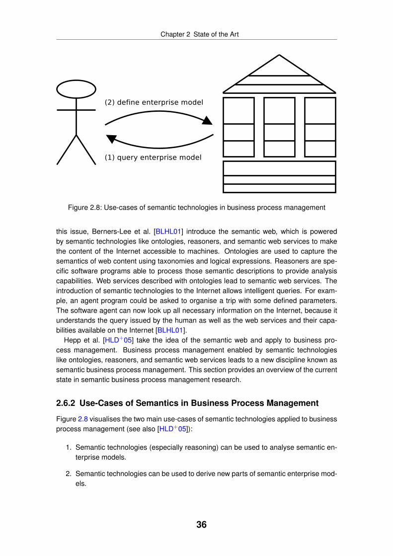
Chapter 2 State of the Art
Figure 2.8: Use-cases of semantic technologies in business process management
this issue, Berners-Lee et al. [BLHL01] introduce the semantic web, which is poweredby semantic technologies like ontologies, reasoners, and semantic web services to makethe content of the Internet accessible to machines. Ontologies are used to capture thesemantics of web content using taxonomies and logical expressions. Reasoners are spe-cific software programs able to process those semantic descriptions to provide analysiscapabilities. Web services described with ontologies lead to semantic web services. Theintroduction of semantic technologies to the Internet allows intelligent queries. For exam-ple, an agent program could be asked to organise a trip with some defined parameters.The software agent can now look up all necessary information on the Internet, because itunderstands the query issued by the human as well as the web services and their capa-bilities available on the Internet [BLHL01].
Hepp et al. [HLD+05] take the idea of the semantic web and apply to business pro-cess management. Business process management enabled by semantic technologieslike ontologies, reasoners, and semantic web services leads to a new discipline known assemantic business process management. This section provides an overview of the currentstate in semantic business process management research.
2.6.2 Use-Cases of Semantics in Business Process Management
Figure 2.8 visualises the two main use-cases of semantic technologies applied to businessprocess management (see also [HLD+05]):
1. Semantic technologies (especially reasoning) can be used to analyse semantic en-terprise models.
2. Semantic technologies can be used to derive new parts of semantic enterprise mod-els.
36

Chapter 2 State of the Art
In the first use-case, semantic technologies are used to discover so far unknown factsfrom the enterprise model. This is possible, because the content of the enterprise modelis processable by machines. For example, a food trading company is influenced by a newregulation released by the EU Commission or some other government organisation. Thenew regulation defines that certain kinds of vegetables must be sold within a shorter timeperiod than before. The food trading company has to implement this regulation. Other-wise, it will loose its licence. A business expert has to analyse all as-is processes to findout those processes affected by the new regulation. This manual analysis work can besimplified if semantic technologies are used to query a semantically enabled enterprisemodel. The business expert defines a query based on the domain ontology used in thecompany. A reasoner uses the query as well as the content of the enterprise model todiscover all business processes and other elements of the enterprise affected by the newregulation.
In the second use-case, semantic technologies are used to generate or at least partiallydefine new elements of the enterprise model. For example, a business process is anno-tated with semantic descriptions specifying what capabilities are expected by each functionso that they can be automated. Semantic web service discovery (see subsection 2.5.2)is used to find matching web services and reasoning techniques are used to derive anexecutable process model. If two interacting web services use different data structures, amediator can be used to moderate between the different data formats. This is possible,because the data formats of the web services are specified semantically, too.
Semantic business process management also promises bridging the business-IT divide[HLD+05] as described in subsection 2.1.5. Instead of forcing business experts to apply ITconcepts in business process modelling or asking IT experts to get familiar with businessadministration knowledge, an ontological mapping is established between both domains.Business experts and IT experts still use their own specific languages and methods, butthey are integrated on a more abstract level through ontological mapping.
Semantic business process management is based on the assumption that all aspects ofan enterprise model can be captured semantically. Therefore, ontologies must exist for thedifferent aspects of an enterprise model. The following subsection introduces the currentlyavailable ontologies for semantic business process management.
2.6.3 Ontologies for Semantic Business Process Management
Ontologies are the backbone of semantic business process management, because theycapture the content in a machine processable way. “An ontology is an explicit specificationof a conceptualization” [Gru93, p. 1]. Ontologies are created in a development processcalled ontological engineering [MI96, GPFLC04]. This development process involves cap-turing the knowledge to be formalised. The knowledge is turned into competence ques-tions. The competence questions are used to later check if the formalised ontology is ableto answer the questions. Similar to software development, designing an ontology is aniterative approach, because the domain described is evolving while designing the ontology[Hep07].
An early version of an ontology for semantic business process management is pre-
37

Chapter 2 State of the Art
BPMOLegend:
UPO
BRO
sEPC sBPMN sBPEL
mining & analysis
ontologies
organisational
ontologies
maps to
imports
set of ontologies
ontology
Figure 2.9: Ontology stack for semantic business process management [HR07, PBvL+08,SUP07]
sented by Uschold et al. [UKMZ98] as “Enterprise Ontology”. The enterprise ontology pro-vides concepts for organisational modelling, strategy modelling, process modelling, andresource modelling. Even though the enterprise ontology is quite comprehensive, it doesnot provide support for current modelling languages used in industry. Furthermore, theenterprise ontology is provided as one single definition not allowing replacing or extendingparts of it with other ontologies.
The SUPER9 research project, a public integrated project financed by the EU Com-mission, proposes a stack of ontologies to represent the various aspects of an enterprisemodel [HR07, PBvL+08, SUP07]. A simplified version of the SUPER ontology stack forsemantic business process management is shown in figure 2.9. All ontologies are definedwith WSML [FLP+06]. In contrast to the enterprise ontology [UKMZ98], there is not a sin-gle ontology representing all aspects of an enterprise model. The upper process ontology(UPO) [HR07, PBvL+08, SUP07] is used to integrated the other ontologies in the stack bydefining common concepts like process, agent or role.
A successful adoption of semantic business process management in industry is very un-likely if existing enterprise models cannot be reused. To enable reuse, the ontology stackprovides support for existing modelling languages like EPC and BPMN (see figure 2.9).The sEPC ontology [FKS08] is introduced for semantic business process modelling usingthe EPC modelling language. Besides the elements defined by the EPC modelling lan-guage, processes can be described semantically like annotating a function with a WSMOgoal [FLP+06]. Similar work is available for BPMN with the sBPMN ontology [AFKK07].The sEPC and sBPMN ontologies provide similar concepts, which are mapped to the busi-ness process modelling ontology (BPMO) [PBvL+08, SUP07]. In addition, BPMO is usedto link the two process modelling ontologies to other ontologies like the set of organisationalontologies. The organisational ontologies are not depicted in detail, but a typical exampleis an ontology for defining business goals [MK08]. Additional ontologies are available orprepared, e. g. to model organisational structures or strategies.
BPMO facilitates the transformation of business process models into executable ones[PBvL+08], because only a single transformation is required instead of providing a trans-
9The author of this thesis is a member of the SUPER research project (http://www.ip-super.org/).
38

Chapter 2 State of the Art
formation for every business process modelling language to be supported. The ontol-ogy stack also provides an ontologised version of BPEL, namely the sBPEL ontology[NWvL07]. In contrast to SA-WSDL [FL07], the sBPEL ontology does not only add linkspointing to semantic descriptions to BPEL, but embeds the semantic descriptions directlyin BPEL. For example, a new activity to invoke a semantic goal is provided. The semanticdescriptions are based on WSMO [FLP+06] and are not solely used to support semanticweb service discovery during runtime, but also to enable process mediation to integrateheterogeneous processes and data definitions.
The behavioural reasoning ontology (BRO) [Nor08] enables temporal reasoning. Anadditional set of ontologies is used to enable semantic process mining and analysis ofexecuted business processes [PDAdM08]. Besides those core ontologies of the stack, it ispossible to add domain specific ontologies. For example, Frankowski et al. [FRS07] definean ontology for the telecommunication company Telekomunikacja Polska.
At different points in the ontology stack, semantic descriptions of web services are used.Those semantic descriptions are expected to be based on WSMO [FLP+06]. WSMOproposes four main components to describe semantic web services, namely: ontologies,web services, goals, and mediators [FLP+06]. Ontologies are used to define terminologyspecific for the semantic web service. Web services provide the actual implementations ofthe semantic web service. Goals are used to describe the capabilities of the semantic webservice from a user perspective. Here, the ontologies defined are used. Finally, mediatorsdescribe mechanisms to resolve interoperability problems. There are other ontologiesavailable for describing semantic web services, e. g. OWL-S [MBH+04]. OWL-S is meantto support discovery, invocation, composition, and monitoring of semantic web services.
2.6.4 Methodology and Applications
Besides providing the necessary ontologies, it is also important to provide guidance howto apply them. The SUPER methodology [WMF+07, dFMM+08, WHMN07] defines alifecycle consisting of four phases:
• In the modelling phase, business processes are captured using the sEPC or sBPMNmodelling language. Besides defining the business process, semantic annotationsare added to the models so that they are machine processable. Those semanticannotations allow auto-completion of processes, because similar already existingprocess models can be discovered while modelling.
• In the implementation phase, business processes are transformed into executableones. For example, sBPEL representations are generated. Also, semantic web ser-vices, which are able to support the semantically annotated functions in the businessprocess model, are discovered. If no semantic web service exists, service compo-sition is used. During the implementation phase, also the necessary deploymentinformation is generated.
• In the execution phase, the semantic business process is executed on a semanticexecution engine. This execution engine supports the discovery of semantic webservices during runtime if requested. Also, semantic web services can be invoked.
39
Chapter 2 State of the Art
• In the analysis phase, executed business processes are analysed so that they canbe optimised [CAdMZ+07]. Also semantic process mining techniques are used toextract so far unknown process models from execution logs [AdMPvdA+07] or toextract ontologies.
This short overview of the SUPER methodology for semantic business process man-agement shows that it mainly focuses on business process automation. At the currentpoint, semantic business process management focuses on a technological definition ofbusiness process management, similar to what Weske [Wes07] presents for non-semanticbusiness process management (see also subsection 2.1.1). However, preliminary workexists focusing on other elements of business process management like compliance man-agement. For example, El Kharbili et al. [EKSMP08b] introduce a framework for semanticcompliance management. In this framework, regulations and laws are broken down intorules, which are semantically defined. Those semantic rules are used to check if a se-mantic enterprise model complies with those rules. The approach taken is similar to thevalidation techniques applied within the OrViA research project (see subsection 2.3.4), buthere a different set of technologies is used.
2.6.5 Tools for Semantic Business Process Management
Semantic business process management can be understood as a modelling method asdefined by Karagiannis and Kühn [KK02] and as discussed in section 1.1. Therefore, se-mantic business process management is not yet a complete modelling method by providinga modelling technique consisting of a modelling language (i. e. the ontologies introduced insubsection 2.6.3) and a modelling procedure (i. e. the methodology discussed in subsec-tion 2.6.4). Semantic business process management must also provide tools to leveragethe content defined with the modelling technique. As semantic business process manage-ment is still a young research discipline, only few tools are available.
Dimitrov et al. [DSSK07] provide an extension for the ontology development softwareWSMO Studio [DSKM07], which allows modelling of BPMO processes in a visual mannerusing the BPMN notation. In a similar effort, Born et al. [BHK+08] provide an extensionof SAP’s BPMN modelling tool Maestro, which allows creating sBPMN processes andinitiating semantic process composition. Maestro is not a product available to ordinaryusers, but instead it is a research prototype used at SAP to evaluate new technologies.
Preliminary work on a semantic BPEL execution engine exists as well. In [vLND+07],the authors describe an architecture of such an execution environment. One importantcomponent is the semantic service bus, which provides access to reasoning services andfunctionality to invoke semantic web services. Here, existing environments like WSMX[HCM+05] and IRS III [DCH+04] can be reused. Currently, the authors of those two en-vironments are collaborating to create a reference architecture of a semantic executionenvironment as a public OASIS standard10.
10See the homepage of the belonging technical committee at OASIS: http://www.oasis-open.org/committees/tc_home.php?wg_abbrev=semantic-ex
40

Chapter 2 State of the Art
In another effort focusing on semantic process mining, Alves de Medeiros et al.[AdMvdAP08] describe an architecture of tools based on the ProM platform11. First se-mantic plugins for ProM are already available on ProM’s homepage.
2.6.6 Evaluation
This overview shows that semantic business process management is an actively re-searched area. So far, most efforts are fundamental research either:
• defining the necessary languages [HR07, PBvL+08, UKMZ98, SUP07, FLP+06,FKS08, AFKK07, MK08, NWvL07, Nor08, PDAdM08, FRS07] or
• providing some preliminary tools [DSKM07, DSSK07, BHK+08, vLND+07,HCM+05, DCH+04, AdMvdAP08] or
• outlining overall approaches and methodologies [HLD+05, WMF+07, dFMM+08,WHMN07, CAdMZ+07, AdMPvdA+07, EKSMP08b].
However, empirical evaluation of the proposed technologies to validate the practical rel-evance of semantic business process management is still missing. Also, integration ofsemantic business process management with current modelling methods is not investi-gated yet. Such work would provide feedback, which could be incorporated in researchagendas to realign the research efforts with requirements from the industrial field. It couldalso demonstrate the relevance of semantic business process management to practition-ers, fostering the adoption of it in industry.
11http://prom.sourceforge.net/
41
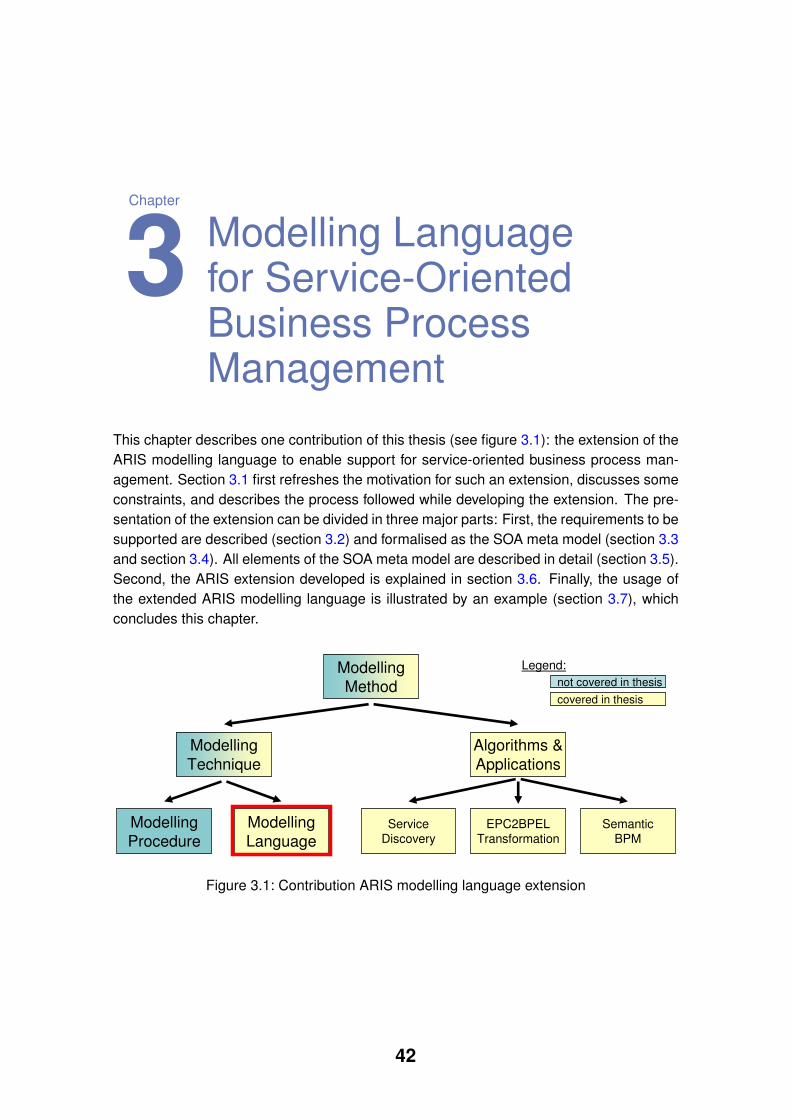
Chapter
3 Modelling Languagefor Service-OrientedBusiness ProcessManagement
This chapter describes one contribution of this thesis (see figure 3.1): the extension of theARIS modelling language to enable support for service-oriented business process man-agement. Section 3.1 first refreshes the motivation for such an extension, discusses someconstraints, and describes the process followed while developing the extension. The pre-sentation of the extension can be divided in three major parts: First, the requirements to besupported are described (section 3.2) and formalised as the SOA meta model (section 3.3and section 3.4). All elements of the SOA meta model are described in detail (section 3.5).Second, the ARIS extension developed is explained in section 3.6. Finally, the usage ofthe extended ARIS modelling language is illustrated by an example (section 3.7), whichconcludes this chapter.
Algorithms &
Applications
Modelling
Method
Modelling
Technique
Modelling
Procedure
Modelling
LanguageService
DiscoveryEPC2BPEL
TransformationSemantic
BPM
Legend:
not covered in thesis
covered in thesis
Figure 3.1: Contribution ARIS modelling language extension
42

Chapter 3 Modelling Language for Service-Oriented Business Process Management
3.1 Overview
3.1.1 Motivation
In literature (see section 2.1), two different understandings of business process manage-ment exist: a business-oriented and a technical understanding. Even though the secondone can be seen as a part of the first one, an integration between both understandings isonly hardly achieved. A similar situation exists for works on SOA as shown in the literaturereview in section 2.2. However, the technical understanding of SOA has far more supportand is clearly leading.
In fact, there are only few attempts trying to integrate those different understandings.A notably exception is the OASIS SOA Reference Model [MLM+06], because it abstractsfrom concrete usages. Besides, other works exist as shown in subsection 2.2.3. How-ever, those works offer only single point solutions by addressing only parts of a modellingmethod. As a matter of fact, there is no complete modelling method covering all parts.For example, CBDI-SAE [CBD07] defines a comprehensive meta model, but it misses amodelling language and modelling procedure.
To overcome this problem, this thesis extends the existing modelling method ARIS tocover all relevant aspects of a modelling method for service-oriented business processmanagement. In this thesis, this is called “ARIS extension”. The ARIS extension was de-signed in a structured development process as described in subsection 3.1.3. The designof the ARIS extension was also constrained by several points, which are discussed in thefollowing subsection.
3.1.2 Constraints
The design and implementation of the ARIS extension was constrained by the followingpoints discussed below. The points are general rules by IDS Scheer applying to all ARISextensions done. They try to prevent ARIS modelling method getting too complex.
1. The ARIS extension must enable reuse of as many existing ARIS models as possibleto preserve users’ investments. Introducing a completely new modelling language isnot a valid solution.
2. The ARIS extension must be fully integrated with the existing ARIS modelling lan-guage. This includes reusing as many existing objects and diagrams as possible.
3. Relying on pilot users is not possible, because users expect to receive a solutionrather than standardising their competitive advantage.
4. The skill sets of the typical ARIS user must be taken into account. Internal useranalysis at IDS Scheer shows that most ARIS users have no natural science normathematical background but instead studied business administration and relatedsocial science subjects.
5. There are many software modelling languages available like UML, which must beintegrate if possible.
43
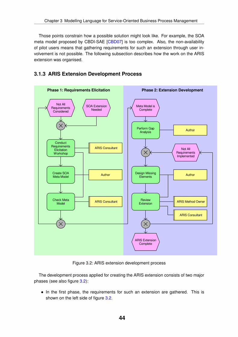
Chapter 3 Modelling Language for Service-Oriented Business Process Management
Those points constrain how a possible solution might look like. For example, the SOAmeta model proposed by CBDI-SAE [CBD07] is too complex. Also, the non-availabilityof pilot users means that gathering requirements for such an extension through user in-volvement is not possible. The following subsection describes how the work on the ARISextension was organised.
3.1.3 ARIS Extension Development Process
SOA ExtensionNeeded
Not AllRequirementsConsidered
ConductRequirements
ElicitationWorkshop
Create SOAMeta Model
Check MetaModel
Meta Model isComplete
Perform GapAnalysis
Design MissingElements
Not AllRequirementsImplemented
ReviewExtension
ARIS ExtensionComplete
ARIS Consultant
ARIS Consultant ARIS Method Owner
Author Author
Author
ARIS Consultant
Phase 1: Requirements Elicitation Phase 2: Extension Development
Figure 3.2: ARIS extension development process
The development process applied for creating the ARIS extension consists of two majorphases (see also figure 3.2):
• In the first phase, the requirements for such an extension are gathered. This isshown on the left side of figure 3.2.
44
Chapter 3 Modelling Language for Service-Oriented Business Process Management
• In the second phase, the ARIS extension is developed based on the requirementsgathered before. This is shown on the right side of figure 3.2.
Figure 3.2 shows the different steps of the development process. To gather require-ments, a workshop with IDS Scheer consultants working in the domains enterprise ar-chitecture management, business process automation, IT architecture management, andgeneral business process management was conducted. Afterwards, the requirementswere turned into the SOA meta model presented in section 3.4, also using other exist-ing work on this topic (see subsection 2.2.3 for related work). This SOA meta model wasreviewed by the consultants. Those three steps were repeated several times to ensure allrequirements are reflected in the SOA meta model. After finishing the SOA meta model,the second phase of the development process was started.
During the second phase, first a gap analysis was performed. The existing ARIS mod-elling language was compared with the SOA meta model to find those parts of the SOAmeta model not covered yet by the ARIS modelling language. The gap analysis is pre-sented in subsection 3.6.2. If a gap was identified, the gap was closed by designing themissing parts. Those extensions were reviewed by the ARIS method owners as well as theconsultants, who were involved in requirements elicitation. The method owners providedfeedback whether the proposed extension follows the guidelines of the ARIS modellingtechnique. The consultants checked that all their requirements are fulfilled in the designof the ARIS method extension. After no further gaps could be identified, the design of theARIS extension was considered to be complete.
The following sections first present the identified use cases to be supported by theARIS extension (section 3.2), considerations about a service description (section 3.3),an overview of the SOA meta model (section 3.4), a detailed look at the elements of theSOA meta model (section 3.5), the ARIS modelling language extension (section 3.6), andan example illustrating the ARIS extension (section 3.7).
3.2 Use Cases to be Supported
3.2.1 Overview
From an abstract point of view, it is the aim of the ARIS extension to support businessexperts in creating a business-oriented service description. Such a service descriptionhelps business experts to evaluate the capabilities provided by a service and to decide ifa service should be used. A comprehensive service description does not solely detail thecapabilities of a service, but also who implements the service, who is responsible for theservice description, and how the service can be used. The main use cases are (partlybased on [OEtH02]):
• Service discovery: A potential user defines his need and all existing and availableservices having the necessary capabilities are suggested.
• Service composition: Several services are combined to provide a more complexcapability.
45

Chapter 3 Modelling Language for Service-Oriented Business Process Management
• Service substitution: If a currently used service becomes unavailable, the service isreplaced with another service with similar capabilities.
• Service governance and management: Creating and maintaining a service architec-ture without redundancies and with clearly defined responsibilities.
Those use cases are further described in the following subsections. In reality, thoseuse cases are interrelated. For example, service discovery requires up-to-date servicedescriptions, which is the task of service governance. Also, service substitution mightdepend on service discovery so that a replacement can be identified quickly.
3.2.2 Service Discovery
The service description defines which capabilities are provided by a service. Therefore, theservice description is a central information object for potential service consumers trying toidentify a service for their needs. By comparing the offered capabilities with the own needs,a service consumer decides whether the usage of the service is possible and beneficial.
This comparison of need and capability is similar to general market mechanisms relyingon supply and demand. Services are suppliers of capabilities and service consumers aredemanders of needs. The evaluation of a service is not limited to the capabilities, but itmust also include the conditions under which the capabilities are provided. For example,the service usage creates costs, which must be covered by the service consumer. If theservice consumer (e. g. a company department) does not pay them directly, it will paythem indirectly by creating enough business value to cover the costs of an IT department.Besides financial conditions, there might be other conditions like the temporal or spatialavailability of the service.
It is also possible that the service itself defines conditions to be met by the serviceconsumer. For example, a service might define that all communication must be encrypted.A service consumer issuing a non-encrypted request will be rejected in such a scenario.
The service description is an offer by the service provider. The offer is binding meaningthat the service must provide the advertised capabilities if requested. The OASIS SOAReference Model [MLM+06] characterises this as “willingness”.
Besides providing the necessary ARIS extension to describe a service so that it canbe discovered, this thesis also contributes a service discovery application supporting aservice consumer in discovering a matching service for a function in a business process.Here, service discovery is done during design-time while the business expert is creatinga business process model. This application is described in chapter 4. The applicationsemantic business process management uses a formalised service description so that theservice description is machine processable. A prototype is provided demonstrating servicediscovery during process execution. This application is described in chapter 7.
3.2.3 Service Composition
It is common to not only invoke a single service, but instead to use several services toconsume a more complex capability. Such a service composition can be implemented
46

Chapter 3 Modelling Language for Service-Oriented Business Process Management
differently. For example, based on a business process an executable service orchestra-tion is created. This service orchestration itself is provided as a service. For a serviceconsumer, it does not make a difference if a single service or a service composition isinvoked. Another possibility for service composition is the combination of services in asoftware architecture. Such an approach is based on previous work done in the area ofcomponent-oriented software engineering like [Szy97, HS00].
Having standardised interfaces is a fundamental requirement of service composition. Inaddition, the interfaces must be documented in the service description. Only if servicesprovide their functionality through standardised interfaces, which can be integrated easily,service composition can be done. However, having standardised interfaces does not meanservices must be implemented with the same technology. The service composition isbased on the service interface and the service description, but the technology behind isnot visible.
This thesis extends the modelling language ARIS to cover all aspects necessary forservice composition. In addition, an exemplarily application is developed demonstratinghow to turn a business process modelled with the EPC notation into a service orchestrationbased on BPEL. The belonging application generates a service interface for the BPELprocess as well, so that it can be consumed like any other service. This application isdescribed in chapter 5.
3.2.4 Service Substitution
The service substitution use case adds details to a service description so that a servicewith similar capabilities can replace a currently used one. A substitution is only possibleif the substitute has no incompatible capabilities or conditions. For example, if a currentlyused service supports encrypted as well as non-encrypted invocation, a substitute canonly constrain the communication to encrypted if the service consumer also supports anencrypted request.
Service substitution is important in failover scenarios. Here, a service becomes unavail-able, e. g. because of hardware failure. The service must be replaced immediately by asubstitute to ensure the operation of the business process or company. Therefore, ser-vice substitution requires that services with similar or equal capabilities are described in asimilar way so that a substitute can be found easily. Also, the ability to explicitly define asubstitute might be needed in some cases.
3.2.5 Service Governance and Management
Services and their development must be planned, maintained, and continuously improved.The belonging activities are summarised as service governance or service management.Activities can be grouped in operational, tactical, and strategical tasks.
Operational activities focus on a short timeframe. They ensure the daily availability ofdeployed services. They also monitor and control the current execution of services. In caseof breakdown, it is an operational task to provide a substitute if the failed service is criti-cal for the operation of the company. Tactical tasks are focused on a midterm timeframe.
47

Chapter 3 Modelling Language for Service-Oriented Business Process Management
staticdynamic static dynamic
External Internal
Figure 3.3: Views and aspects of service description
Here, the deployment or replacement of services is planned and implemented. Strategicaltasks have a significant longer timeframe. For example, they focus on the developmentof the overall service architecture like defining the necessary service categories to groupservices. They also establish the necessary means to enable service usage like train-ing potential service consumers in evaluating service descriptions. A service descriptionmust enable service governance and management for operational, tactical, and strategicaltasks.
The following section introduces some basic considerations about a service descriptionas a systematic. It details which views, aspects, and levels must be represented by aservice description.
3.3 Service Description Systematic
3.3.1 Aspects and Views
This section introduces a systematic, which defines the basic structure of a service de-scription. This systematic is mainly based on general system theory [vB76], because aservice can be viewed as a system. In that sense, a service consists of elements andrelations among those elements. There are static as well as dynamic relations possiblebetween different elements. Therefore, a service description must distinguish between dy-namic and static aspects as shown in figure 3.3. For example, a company might define aservice architecture decomposing some high-level services into detailed ones. Here, staticrelations are used to build a hierarchy of services. A service might not be always avail-able, for example depending on location and time. Here, a dynamic relation is establishedbetween service, location, and time.
As outlined in the previous section, there are different use cases, which a service de-scription has to support. Service governance and management is mainly an internal activ-ity not completely visible to service consumers. In contrast, elements of a service descrip-tion used during service discovery must be available externally to enable the evaluationof the capabilities by a potential service consumer. Therefore, a service description mustdistinguish between an internal and external view as shown in figure 3.3. The externalview contains all elements relevant for service consumers and which should be visible ex-ternally, whereas the internal view contains all remaining elements. External and internal
48

Chapter 3 Modelling Language for Service-Oriented Business Process Management
staticdynamic static dynamic
External Internal
staticdynamic static dynamic
CIM
PIM
......PSM
Figure 3.4: Levels of service description
view represent dynamic as well as static information. For example, the structure of theservice interface is a static external information. An interaction protocol constraining theinvocation order of service operations is a dynamic external information, because it is im-portant for service consumers to know in which order to invoke certain operations of theservice. In contrast, an information describing the physical deployment of the service is aninternal information, which is not relevant for an outside viewer.
Even though it is clear that a service description must distinguish between internal andexternal view, it is impossible to define which elements belong to which view. Each com-pany has to define on its own, which information must be provided to service consumersand which information is only available internally.
3.3.2 Levels
The service description provides various information of different detail. Also, the servicedescription is used by different users like business experts, IT architects, and system ad-ministrators. Therefore, the service description must distinguish different levels of detailas shown in figure 3.4. This thesis uses the levels defined by model driven architecture(MDA) [MM03] (see subsection 2.3.2), namely:
• The computation independent model (CIM) level describes the service from a busi-ness point of view. A service described on this level can be implemented in manydifferent ways like contracting an external party or providing an IT implementation.
• The platform independent model (PIM) level describes services provided as soft-
49

Chapter 3 Modelling Language for Service-Oriented Business Process Management
ware. However, this level is not bound to any specific technology, so a service canbe implemented e. g. using the W3C stack or based on REST.
• The platform specific model (PSM) level describes services based on a specifictechnology or framework like web services. A web service description provided inthe WSDL format is such a platform specific model.
In this model, a level is always independent from the levels below. For example, aservice might be described on CIM level, but the service might be not available as an ITimplementation. In that case, the PIM and PSM levels are missing. In another case, aservice might feature several IT implementations and so several PIM and PSM levels areavailable.
Most current work on SOA focuses on the PIM and PSM level by providing standardsto describe technical service artefacts. A service description independent of IT is ignored.This hinders an integration with business process management, because business pro-cesses are described independent of IT by business experts. By adding a computationindependent level to the service description, an integration is enabled. However, only hav-ing a computation independent service description is not enough either, because moretechnical descriptions are required for business process automation.
3.3.3 Service Categories
In business process management it is common to group business processes in differentcategories like core processes and supporting processes [SS08a]. The same is useful forservices. This requirement can also be found in SOA literature (e. g. [Jon06]). Appliedto the service description systematic, it must be possible to represent different servicecategories as shown in figure 3.5.
Each service is assigned to exactly one category. To allow an unambiguous assign-ment, clear criteria must be defined for each category. Those criteria must be reworkedif a service cannot be clearly assigned to a category. Besides defining criteria, it is alsoimportant to define the viewpoint from which values for each criterion for a given serviceare defined. For example, a company may classify a service to send short text messageto mobile devices as infrastructural service. However, a company, which is operating amobile network, may classify such a service as a value adding service, because it is prob-ably one of their cash cows. That shows that defining the viewpoint is important for servicecategorisation. It is a task of service governance to define categories and the belongingcriteria. Also, the categorisation of each service must be checked from time to time to seeif a service still belongs to a category. There is no guarantee that a service belongs alwaysto the same category for its whole lifetime.
Categorisation of services can be used to define specific management and governanceprocesses. For example, services directly impacting the overall performance of the com-pany may need a more careful management than a service, which is very seldom used.Because of limited resources, it can be decided to only focus on services of a specificcategory ignoring all other services. Maintenance of services in different categories might
50

Chapter 3 Modelling Language for Service-Oriented Business Process Management
CIM
PIM
static static dynamic
static static dynamic
dynamic
dynamic
External Internalvalue adding
supporting
infrastructural
Figure 3.5: Service categories
also require different skills. For example, an infrastructural service might require compre-hensive IT knowledge whereas maintenance of a value adding service relies on businessadministration knowledge.
The number of categories and the category names are company specific. It is impossi-ble to provide a pre-defined set. Therefore, a modelling language for service descriptionmust be customisable. However, this thesis suggests introducing the following three cate-gories with the following criteria (see also figure 3.5):
• Value adding services are the core of each company. According to their name,they directly contribute to the success of the company by generating business value.Value adding services are provided to customers and are therefore visible externally.It can be expected that only few value adding services exist. Jones [Jon06] calls thiscategory business services and estimates their number to less than 10. It is unlikelythat a value adding service can be implemented completely through IT. Probably, avalue adding service is a complex composition of many services, which are not allimplemented through IT. Possible criteria fulfilled by a value adding service are:
– directly contributes to the value creation of the company
– cannot be substituted
– is externally visible
– contains business logic
– cannot be implemented completely by IT
– there are less than 10 services of this kind
51

Chapter 3 Modelling Language for Service-Oriented Business Process Management
– often offered to customers
• Supporting services are the building blocks of value adding services. They providecommon business logic, which is reused in many places. Therefore, supportingservices have a high degree of reuse. Typical examples of supporting services areaccounting, human resource, and payroll management. There is usually a good soft-ware coverage for supporting services so that they can be implemented using stan-dard software packages. It is possible to substitute a supporting service. However,such a substitution must be carefully planned and managed as a change project.Possible criteria fulfilled by a supporting service are:
– service supports value creation
– contains business logic
– can be substituted, but not on short notice
– is not offered to customers
– can be implemented through standard software
– high degree of reuse
– there are several hundred services of this kind
• Infrastructural services represent the many individual IT functions needed to oper-ate a company. Those services do not support value creation, even though they canbe used in a service composition creating value. However, infrastructural servicesonly provide technical capabilities, which can be substituted easily and on short no-tice. Such services are not externally visible and a very high degree of reuse canbe expected. Such services are normally provided by application systems, standardsoftware, middleware products, and external service providers. Possible criteria ful-filled by an infrastructural service are:
– does not support value creation
– does not contain business logic
– can be substituted on short notice
– not externally visible
– probably completely automated execution
– very high degree of reuse
– there can be several thousand of this kind
Most SOA literature and approaches focus only on infrastructural services, ignoring themore abstract service categories. The following section presents the SOA meta model,which relies on the systematic described in this section. The SOA meta model supportsdynamic as well as static aspects, which can be distributed between an internal and exter-nal view. The SOA meta model describes a service on different levels of abstraction (i. e.CIM, PIM, PSM) and enables the definition of company specific service categories.
52

Chapter 3 Modelling Language for Service-Oriented Business Process Management
Logical DataObject
Function
Capability
Service Type
Process
Software Service
Appliance
n
describes
m
mhas input/outputn
SLA
n
describes
m
Business Object1owns
n
requires1
realises n
1
realisesn
1
encompassesn
Software ServiceOperation
WSDL Specific UML Models
WSDL Service WSDL Operation
WSDL Porttype
Optional (Blueprinting)
Generic UML Models
TechnicalSoftware Service
TechnicalSoftware Service
Interface
TechnicalSoftware Service
Operation
Function
Capability
1 has n
1
groups
n
hascontains
BPEL Activity
n
supports
m
n
describes
m
invokes/receives
n
realises
1
containshas
n
describes
m
CIM
PIM
PSM
1
n
1
n
implemented by
Business Object
1ownsn
nhas input/outputm
Capabilityrequires
Capability
requires
Logical DataObject
KPIdefines
Org. Elementn
provides1
Org. Elementowns
supports
Logical DataObject
Company Goal Project
influences/leads
created/extended in
Org Element
Product/Servicen
1
realises
input/output
input/output
owns
Requirementdescribesbelongs to
Figure 3.6: SOA meta model
3.4 SOA Meta Model
Figure 3.6 shows the complete SOA meta model. The SOA meta model was created bygathering requirements from consultants. Those requirements were formalised as the SOAmeta model (see subsection 3.1.3 for details on the development process). Figure 3.6 usesan informal modelling language to represent the SOA meta model. Rectangles representconcepts of the SOA meta model. Some objects are grouped like the generic UML modelsused on the PIM level to represent a platform independent software service design. Thisgrouping carries no further semantics, but is introduced to make the model more readable.Concepts as well as relations represent elements of a service description.
Using an informal modelling language might not be a good practice. Therefore, part ofthe SOA meta model is available as UML class diagram in figure 3.7 to demonstrate that
53

Chapter 3 Modelling Language for Service-Oriented Business Process Management
Service Type Service Owner
Project Capability
Software Service Type
Web Service (WSDL) CORBA Service
Service Provider
Business Process
Workflow Process
GeneralizationGeneralization
DependencyDependencyService Level
AgreementCompany Goal
OrganisationalElement
GeneralizationGeneralization
GeneralizationGeneralization
RealizationRealization
Appliance
GeneralizationGeneralization
XPDL BPEL
DependencyDependency
RealizationRealizationRealizationRealization RealizationRealization
«use»
Usage
«use»
Usage
«use»
Usage
«use»
Usage
realises
1
*
realises
1
*
realises
1
*
realises
1
*
realises
1
*
realises
1
*
RealizationRealization
«use»
Usage
«use»
Usage
RealizationRealization
«encompass»
0..1
*
«encompass»
0..1
*
CIM
PIM
PS
M
Figure 3.7: Subset of SOA meta model represented as UML class diagram
the informal description can be formalised. Using UML for meta modelling is an acceptedapproach according to Karagiannis and Kühn [KK02]. The UML class diagram only showsa subset of the SOA meta model, because the notation requires more space. Therefore,in the following sections the informal representation shown in figure 3.6 is used while de-scribing the different concepts of the SOA meta model.
The structure of the SOA meta model follows what is described in the systematic in sec-tion 3.3. The SOA meta model is structured into the three MDA levels CIM, PIM, and PSM.Dynamic as well as static aspects are not distinguished in the SOA meta model, becausethe SOA meta model describes all relations between the concepts. However, dynamicas well as static aspects are later distinguished in the modelling language developed byproviding different diagrams (see subsection 3.6.4). As discussed in the systematic in sub-section 3.3.1, it is impossible to define, which elements of a service description belong tothe internal and external view. Therefore, the SOA meta model does not assign conceptsto specific views.
The different elements of a service description, represented as concepts and relationsin the SOA meta model, are described in the following section.
54

Chapter 3 Modelling Language for Service-Oriented Business Process Management
3.5 Service Description Elements
3.5.1 Overview
The SOA meta model shown in figure 3.6 consists of several concepts and relations be-tween the concepts. Each concept represents an element of a service description. It canbe seen that most concepts focus on the CIM level and fewer concepts are provided forthe PIM and PSM level. Of course, there are important aspects on those levels as well, butthose levels are already covered well by the ARIS modelling language and are thereforenot included in the SOA meta model. For example, it is possible to model on which kind ofhardware a software service is deployed. This is already possible prior the modelling lan-guage extension contributed in this thesis. The following subsections describe the differentelements, thereby specifying the scope of the modelling language to be developed.
3.5.2 Capability
Entities like organisations, IT systems, and business processes have a set of capabilities.Their capabilities enable them “to solve or support a solution for the problems they face inthe course of their business” [MLM+06, p. 8]. A capability is a descriptive element docu-menting a system. In the specific case of the SOA meta model (see figure 3.6), capabilitiesare used to describe service types and software service types. Capabilities can be used todescribe functional and non-functional properties. However, in case quantitative descrip-tion is possible, defining service level agreements (SLA) is recommended, because theyare more expressive than capabilities. For a discussion on non-functional properties seesubsection 3.5.5.
The SOA meta model does not limit the way capabilities are defined. The reviewedworks use different formalisms for describing capabilities and there seems to be no con-sensus among them. For example, in WSMO [FLP+06] a formal language based on logicalexpressions is used. On the other hand, MODAF [MOD07] suggests defining a taxonomy.The SOA meta model allows linking capabilities to more detailed and maybe even for-malised descriptions like WSMO goals, but such a description is not mandatory. Chapter 7introduces an application using such formalised descriptions.
A capability is always global and can be reused to describe different services. There-fore, a capability must clearly define the context it can be used in. Reusing capabilitiesamong services allows identifying services with similar capabilities (see use case servicesubstitution in subsection 3.2.4), which is important e. g. in case of service failure or whileharmonising a service architecture.
To ensure reuse of capabilities, the capability architecture must be actively managed.Unused capabilities must be reviewed and newly created capabilities must be integrated toprevent redundancy. The vocabulary used for naming capabilities must be standardised toprevent competing definitions and misunderstandings. If the capabilities of an entity like anIT system are changed, this must be manually reflected in the belonging models. This is amanagement issue and cannot be automated. Specific methods like ontological engineer-ing [MI96, GPFLC04] must be applied for creating a sound capability architecture. The
55

Chapter 3 Modelling Language for Service-Oriented Business Process Management
modelling procedure ARIS Value Engineering (AVE) provides specific guidelines. How-ever, AVE is not part of this thesis.
3.5.3 Service Type
The service concept presented in MacKenzie et al. is generic enough to not only coversoftware or web services, but instead any “mechanism enabling access to one or morecapabilities” [MLM+06, p. 12]. A similar view can be found in service science [Teb06],where a service is also not limited to technology. This abstract notation of a service is alsopresent in the SOA meta model by introducing the service type concept as a mechanismenabling access to a set of capabilities. A similar construct called “notional service” canbe found in CBDI-SAE [CBD07].
Service types themselves can be grouped into different categories like business ser-vices, decision services, supporting services, infrastructure services, etc. (see subsec-tion 3.3.3). There is no consensus on useful service categories, because the categori-sation depends on the company’s context. Therefore, the SOA meta model does notdistinguish between different service types. However, it allows the definition of differentsubtypes so that it is possible to group services into categories.
The functionality made available by the service type is described by relating capabilitiesto it. A capability can be reused by several service types to describe similar service types.Besides, the service type is related to much more concepts in the SOA meta model. Thepurpose of those relations is described in the following subsections.
3.5.4 Service Owner
Each service type has a service owner. The service owner is responsible for maintainingthe service type’s description and advertising the service offering. In addition, the serviceowner is responsible for reviewing change requests like newly requested or changed ca-pabilities. It might be also the task of the service owner to manage the development ofthe service. If the tasks are too complex to be handled by a single person, the role canbe shared. Knowing who is responsible for a service is important for external service con-sumers as well as internally. Therefore, this information should be available in the externalview of the service description.
3.5.5 Non-Functional Description
Describing a service using capabilities has the disadvantage that it is only an unstructureddefinition. For example, if a capability defines that a service must be reacting quickly to aservice request, it is unclear what “react quickly” means. In such cases, it is better to useconcrete quantitative definitions instead of relying on “soft” specifications. Usually, sucha quantitative definition describes the circumstances under which a service is provided.Such descriptions can be seen as non-functional properties of the service. However, whiledeveloping the SOA meta model there was no consensus among the involved consultantson a clear definition for functional and non-functional properties. Therefore, capabilities are
56

Chapter 3 Modelling Language for Service-Oriented Business Process Management
not divided in those two categories. Instead, the SOA meta model shown in figure 3.6 onlydistinguishes between capabilities and service level agreements (SLA), which are definedthrough key performance indicators. It is up to the users of the ARIS extension to definethe SLAs needed to correctly describe their services.
According to O’Sullivan et al. [OEtH02], non-functional properties can be further divided:
• Availability refers to the temporal and spatial constraints applied to a service[OEtH02]. This requirement is detailed in subsection 3.5.12.
• Channels constrain the way a service is accessed [OEtH02]. This is reflected in theSOA meta model by allowing different realisations of a service type as discussed insubsection 3.5.8.
• Charging styles define how service usage must be paid. Typical examples are charg-ing per request, charging per measured unit, and charging based on a ratio of theservice effect (e. g. commission) [OEtH02]. It is expected that capabilities are usedto model the different charging styles.
• Settlements define the obligations to be expected from service usage. For example,a service might be rented for a longer time or a new contract is established eachtime the service is consumed. Additional terms and conditions might be definedfor service usage like a description what happens if something goes wrong duringservice delivery [OEtH02]. Again, capabilities are used to model this informationunless quantitative descriptions can be provided. In that case, SLAs are used.
• Payment obligations define how the service usage must be paid. For example, itmust be defined if the service usage is charged immediately upon request or onlyafter the service request was answered completely [OEtH02]. It is expected thatcapabilities are used to model this information.
• Service quality defines how the service is delivered like reliability and responsive-ness [OEtH02]. That are quantitative descriptions and therefore SLAs are used.
• Security and trust must be defined as well, for example how data send to the serviceis protected [OEtH02]. It is expected that capabilities are used to express this kindof information.
• Ownership and rights received by service usage must be specified as well. Forexample, it must be defined if the service provider is allowed to offer the service toother service requestors as well [OEtH02]. Again, capabilities are used to modelthis information.
This list of non-functional properties shows that a service description must contain manymore details besides the functional description. The details are necessary so that a validlegal contract is established by requesting a service.
57

Chapter 3 Modelling Language for Service-Oriented Business Process Management
3.5.6 Data Description
The SOA meta model shown in figure 3.6 relates the different service concepts on theCIM, PIM, and PSM level to data objects. It can be seen that each service concept canconsume, produce, and own data. It is important to note that different kinds of data areused on the different levels in the SOA meta model. For example, data descriptions onthe CIM level must be independent of computational aspects (i. e. conceptual data modelslike business objects or a shared business vocabulary). Here, a business vocabulary or ataxonomy of the main business terms might be used. In contrast, XML schema definitions(XSDs) may be used on the PSM level.
Consuming and producing data establishes an important link between services andbusiness processes, because functions also consume and produce data. For example, if aservice should support a function, it must be able to consume and produce the same dataas the function does.
Services can also own data. This is an important modelling concept in context of compo-nent oriented software design [Szy97, HS00]. For example, the methodology establishedby Herzum and Sims [HS00] makes heavy use of designing components around centraldata objects. Such components can be represented with the service type. Therefore, aservice type can own data. Such an ownership specifies that all access to the data mustbe made through the service. This is a conceptual requirement, which can be relaxedduring implementation, for example to ensure high performance.
3.5.7 Service Architecture
It might be useful to nest services to build a service architecture. Therefore, the SOA metamodel shown in figure 3.6 allows a recursive relation to the service type concept itself.There is no general rule whether the more fine grained services are visible externally orinternally. Also, it might be possible that only fine grained services can be consumed, butthat those services belong to a more abstract service in the service architecture. Eventhough services can be refined into more fine grained services, it is not defined that thosefine grained services must belong to the same service category as the parent service.
The nesting of services to build a hierarchy of services is a common concept, whichcan also be found in component oriented software design [Szy97, HS00]. Also, it mightbe a use case to model the overall structure of an enterprise using services as shown in[JM05, Jon06].
3.5.8 Available Realisations
Figure 3.6 shows that a service type can be realised or provided in different ways, namely:
• as a software service type
• by an organisation
• as an appliance (combination of hardware and software)
58

Chapter 3 Modelling Language for Service-Oriented Business Process Management
• as a business process
• by a product
Each service provider must have all capabilities specified by the service type. Other-wise, the service provider does not fulfil the service offering as described by the servicetype. It is important to note that the service type itself is not a realisation, which can beconsumed. The service type is only a mechanism to provide access to such realisationsand it is described using capabilities offered by all realisations.
The real-world effects resulting from contracting a service provider must be the samefor all service providers. However, the service realisations provided might differ in the waythey achieve the real-world effects. Therefore, realisations can have additional capabilitiesas long as they do not provide fewer or conflicting capabilities as defined by the servicetype.
3.5.9 Strategy Alignment
In order to align the service architecture with the company strategy, a service type can berelated to company goals. In that way it is possible to model, which company goals aresupported by a service type. The ARIS modelling method supports different methods andtechniques to strategy definition like balanced scorecards. If SOA is not solely understoodas an implementation technology, it is important to align the service architecture with theoverall company goals. The service landscape is informed by the company goals provid-ing support in implementing it. Therefore, relating company goals and other strategicalmodelling concepts to services is important to support strategic business-IT alignment asdefined by Henderson and Venkatraman [HV93].
3.5.10 Project Management Alignment
Similar to the alignment of the service architecture with the overall company strategy, itmust be possible to relate services to projects and programs. Projects and programs areestablished as concrete actions to implement a company strategy. Such actions mightdefine new services or alter existing ones.
In general, the service owner must decide whether the service is changed in a project.Besides modelling that a service belongs to a certain project, it is also important to specifywhich capabilities of the service are added or changed during the project. If a capabilityshould be added to a service in a project, a requirement is created, which also belongs tothe project. After completing the project, the requirement is removed and the new capabilityis added to the service description.
3.5.11 Usage in Processes
Services are introduced to support and structure business activities. Business activitiesare usually described using business process models. Therefore, it must be also possibleto use services in business process models to model that a function in a business process
59

Chapter 3 Modelling Language for Service-Oriented Business Process Management
is supported or even automated by a service. It can be seen in figure 3.6 that the differentservices on the three levels can all be used in process models. However, a service shouldonly be used in those processes, which are on the same abstraction level as the service.For example, it would be wrong to use a service type in a BPEL process. Here, only webservices are used, because BPEL processes and web services are both platform specific.
It is not a trivial task to identify services to be used in a process. One possible approachis analysing the data processed and produced by a function. A service able to supportthis function must also process and produce the same data objects. Another approach isrelying on functional descriptions using capabilities. Here, a function specifies the capa-bilities to be possessed by a service, which should support the function. By analysing theservice descriptions, it is possible to identify services offering the requested set of capa-bilities. Here, user support is needed, because this is a complex task. Especially in caseof big service landscapes it cannot be done manually. Therefore, the application servicediscovery is contributed by this thesis as discussed in chapter 4.
Services are not only used in processes, but the SOA meta model also shows that aprocess is a valid realisation of a service. For example, on the PSM level a BPEL processrealises a web service.
3.5.12 Service Availability
Besides those service description elements represented as concepts in the SOA metamodel shown in figure 3.6, the requirement to model the spatial as well as temporal avail-ability of a service is not represented there.
Spatial availability describes at which (physical or virtual) location a service is provided.This is especially interesting for service realisations. For example, a web service realisinga service type might be available in all offices, but a certain department handling the samerequest might be only available in the headquarter of a company.
Temporal availability describes at which time a service is provided. For example, a webservice realising a service type might be available all the day, but a certain departmenthandling the same request might only be available on work days during working hours. Aservice description must be able to represent such availability information.
3.6 ARIS Modelling Method Extension
3.6.1 Overview
Subsection 3.1.3 described the development process of the ARIS extension, which isshown in figure 3.2. First, the requirements for such an extension were gathered andformalised as the SOA meta model discussed in the previous sections. This part of thedevelopment process is shown on the left side of figure 3.2. The SOA meta model (seesection 3.4) and the belonging systematic (see section 3.3) can be viewed as a require-ments specification defining what should be possible to model with the ARIS modellinglanguage. This requirement specification was input for the development process of theARIS extension, which is shown on the right side of figure 3.2. As a first step, a gap
60

Chapter 3 Modelling Language for Service-Oriented Business Process Management
Logical DataObject
Function
Capability
Service Type
Process
Software Service
Appliance
n
describes
m
mhas input/outputn
SLA
n
describes
m
Business Object1owns
n
requires1
realises n
1
realisesn
1
encompassesn
Software ServiceOperation
WSDL Specific UML Models
WSDL Service WSDL Operation
WSDL Porttype
Optional (Blueprinting)
Generic UML Models
TechnicalSoftware Service
TechnicalSoftware Service
Interface
TechnicalSoftware Service
Operation
Function
Capability
1 has n
1
groups
n
hascontains
BPEL Activity
n
supports
m
n
describes
m
invokes/receives
n
realises
1
containshas
n
describes
m
CIM
PIM
PSM
1
n
1
n
implemented by
Business Object
1ownsn
nhas input/outputm
Capabilityrequires
Capability
requires
Logical DataObject
KPIdefines
Org. Elementn
provides1
Org. Elementowns
supports
Logical DataObject
Company Goal Project
influences/leads
created/extended in
Org Element
Product/Servicen
1
realises
input/output
input/output
owns
Requirementdescribesbelongs to
x
xx x x
xx
xx
x
xx
x
xx
x
x
x
xx
x
x
Figure 3.8: Parts of SOA meta model not supported by ARIS
analysis was performed to identify those parts of the SOA meta model, which cannot berepresented with the ARIS modelling language already today. This gap analysis is pre-sented in subsection 3.6.2. In a second step, the missing elements like new object typesand model types were designed. The newly introduced or changed elements of the ARISmodelling language are described in subsection 3.6.3 and subsection 3.6.4.
3.6.2 Gap Analysis
Figure 3.8 shows, which concepts of the SOA meta model were not represented com-pletely before developing the ARIS extension. A red cross denotes that the concept wascompletely missing. A yellow cross denotes that the concept was present, but used witha different or narrower meaning. For example, the ARIS modelling language allowed de-
61
Chapter 3 Modelling Language for Service-Oriented Business Process Management
scribing application systems independent from the technology they are implemented withusing the “application system type” object type. However, there was no subtype to markapplication system types representing a software service type. This also applies to opera-tions of an application system type.
Prior extending ARIS, there was no object type representing a capability. Instead, anobject type called “information system function” existed, which was used to model thecapabilities of information systems. However, the “information system function” objecttype was mainly used to describe IT capabilities and therefore has a narrower meaningcompared to a general capability able to describe any functionality and not only IT basedones.
There is no object type in the ARIS modelling language to represent an appliance. In-stead, “application system type” object types are used. In a model type called “accessdiagram” it is possible to model that the application system type is bound to a specific kindof “hardware”.
Business objects (i. e. conceptual data objects) are represented in the ARIS modellinglanguage by two object types, namely: “technical term” and “cluster”. Logical data objects(i. e. data objects on the platform independent level) are represented with four differentobject types, namely: “technical term”, “cluster”, “entity type”, and “class”. Those differentobject types are reused and no additional object types are added to the ARIS modellinglanguage for data modelling.
The gap analysis revealed that a service concept independent of IT was almost com-pletely missing in the ARIS modelling language. An object type called “functional cluster”existed, which was part of the proprietary modelling technique “IT city planning” used for ITarchitecture management. A functional cluster groups IT systems with similar capabilities.However, as the functional cluster is used in IT architecture management, it is not consid-ered to be computation independent. Therefore, figure 3.8 shows that no equivalent for theservice type existed in the ARIS modelling language before extending it. As the servicetype concept was missing, it was also not possible to represent the different relations to itas shown in figure 3.8.
The gap analysis revealed the parts of the SOA meta model not yet supported by theARIS modelling language. This information was used to design the ARIS extension. Theadded or changed object and symbol types of the ARIS modelling language are describedin the following subsection.
3.6.3 New or Changed Object and Symbol Types
Figure 3.9 gives an overview of the main changes done to the ARIS modelling languageby the ARIS extension described in this thesis. Changed or new object/symbol types are:“capability”, “service type”, and “software service type”.
CapabilityAs discussed in the previous subsection, the object type “information system function” wasused to describe capabilities of IT systems. This object type was renamed to “capability”lifting its meaning to a computation independent level. This is illustrated in figure 3.9. It wasdecided not to introduce a completely new object type, because no easy to understand
62
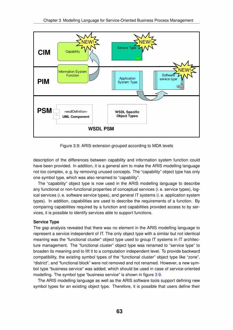
Chapter 3 Modelling Language for Service-Oriented Business Process Management
ApplicationSystem Type
CapabilityService Type
«wsdlDefinition»
UML Component
CIM
PIM
PSM
WSDL PSM
WSDL SpecificObject Types
NEW!
Information SystemFunction
NEW!
Softwareservice type
NEW!
Figure 3.9: ARIS extension grouped according to MDA levels
description of the differences between capability and information system function couldhave been provided. In addition, it is a general aim to make the ARIS modelling languagenot too complex, e. g. by removing unused concepts. The “capability” object type has onlyone symbol type, which was also renamed to “capability”.
The “capability” object type is now used in the ARIS modelling language to describeany functional or non-functional properties of conceptual services (i. e. service types), log-ical services (i. e. software service types), and general IT systems (i. e. application systemtypes). In addition, capabilities are used to describe the requirements of a function. Bycomparing capabilities required by a function and capabilities provided access to by ser-vices, it is possible to identify services able to support functions.
Service TypeThe gap analysis revealed that there was no element in the ARIS modelling language torepresent a service independent of IT. The only object type with a similar but not identicalmeaning was the “functional cluster” object type used to group IT systems in IT architec-ture management. The “functional cluster” object type was renamed to “service type” tobroaden its meaning and to lift it to a computation independent level. To provide backwardcompatibility, the existing symbol types of the “functional cluster” object type like “zone”,“district”, and “functional block” were not removed and not renamed. However, a new sym-bol type “business service” was added, which should be used in case of service-orientedmodelling. The symbol type “business service” is shown in figure 3.9.
The ARIS modelling language as well as the ARIS software tools support defining newsymbol types for an existing object type. Therefore, it is possible that users define their
63
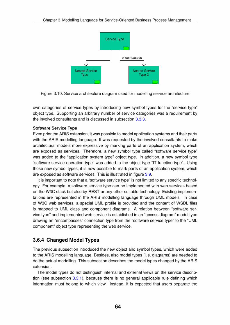
Chapter 3 Modelling Language for Service-Oriented Business Process Management
Service Type
Nested ServiceType 1
Nested ServiceType 2
encompasses
Figure 3.10: Service architecture diagram used for modelling service architecture
own categories of service types by introducing new symbol types for the “service type”object type. Supporting an arbitrary number of service categories was a requirement bythe involved consultants and is discussed in subsection 3.3.3.
Software Service TypeEven prior the ARIS extension, it was possible to model application systems and their partswith the ARIS modelling language. It was requested by the involved consultants to makearchitectural models more expressive by marking parts of an application system, whichare exposed as services. Therefore, a new symbol type called “software service type”was added to the “application system type” object type. In addition, a new symbol type“software service operation type” was added to the object type “IT function type”. Usingthose new symbol types, it is now possible to mark parts of an application system, whichare exposed as software services. This is illustrated in figure 3.9.
It is important to note that a “software service type” is not limited to any specific technol-ogy. For example, a software service type can be implemented with web services basedon the W3C stack but also by REST or any other suitable technology. Existing implemen-tations are represented in the ARIS modelling language through UML models. In caseof W3C web services, a special UML profile is provided and the content of WSDL filesis mapped to UML class and component diagrams. A relation between “software ser-vice type” and implemented web service is established in an “access diagram” model typedrawing an “encompasses” connection type from the “software service type” to the “UMLcomponent” object type representing the web service.
3.6.4 Changed Model Types
The previous subsection introduced the new object and symbol types, which were addedto the ARIS modelling language. Besides, also model types (i. e. diagrams) are needed todo the actual modelling. This subsection describes the model types changed by the ARISextension.
The model types do not distinguish internal and external views on the service descrip-tion (see subsection 3.3.1), because there is no general applicable rule defining whichinformation must belong to which view. Instead, it is expected that users separate the
64

Chapter 3 Modelling Language for Service-Oriented Business Process Management
Capability
Sub Capability 1 Sub Capability 2
encompasses
Figure 3.11: Service architecture diagram used for modelling capability architecture
views on their own and distributed the information between different model type instancesof the same type.
Service Architecture DiagramThe SOA meta model shown in figure 3.6 specifies that it must be possible to build ahierarchy of service types. For this purpose, the model type “service architecture diagram”is used. As shown in figure 3.10, an “encompasses” connection type can be establishedbetween two “service type” object types. The usage of the “encompasses” connectiontype is not constrained by the symbol type of the object types. Therefore, it is possible todo arbitrary nesting between different service types. This is needed, because the numberand naming of symbol types must be customisable so that users can introduce their ownsymbol types (i. e. categories) of service types.
The model type “service architecture diagram” existed before, but was named “enter-prise architecture model” before. It was previously used to model a hierarchy of “functionalcluster” object types. As the belonging proprietary modelling technique “IT city planning”is not used anymore, the model types used before were renamed and reused for service-oriented modelling on a computational independent level.
The model type “service architecture diagram” can also be used to describe a hierarchyof “capability” object types. This is not shown in the SOA meta model, because it wasnot a requirement of the involved consultants. Instead, it was already possible to model ahierarchy of “information system function” object types in the past. As the “capability” objecttype is replacing the “information system function” object type, this model concept must bepreserved in the ARIS modelling language. Similar to the hierarchy of service types, alsoan “encompasses” connection type can be modelled between “capability” object types inthe “service architecture diagram” model type as shown in figure 3.11.
A service architecture diagram can also be used to relate capabilities to service types.Here, the connection type “encompasses” is established pointing from a “service type” ob-ject type to a “capability” object type. However, modelling the capabilities of a service typein the service architecture diagram is not recommended, because the service architecturediagram should contain overall information on the service architecture but not specific in-formation only influencing a single service type. For the latter case, the model type “serviceallocation diagram” should be used, which is introduced in the following paragraph.
65

Chapter 3 Modelling Language for Service-Oriented Business Process Management
Service Type
Capability
encompasses
SoftwareServiceType
supports
Organizational unit
provides
Business Object1
Business Object2
is input for
has output of
Business Object3
is owner of
Organizationalunit type
is responsible for
Process
realizes
Objective
Product/Service
realizes
supports
KPI Instance
is measured by
Figure 3.12: Service allocation diagram
Service Allocation DiagramFigure 3.12 shows the model type “service allocation diagram”. A service allocation di-agram is used to describe an individual service by collecting all necessary information.For example, capabilities can be related to the service type and a service owner can bedefined. The “service allocation diagram” model type existed prior extending ARIS, butthe model type was called “IE context model”. This model type was also used in the nowobsolete modelling technique “IT city planning”.
The connection types used in the “service allocation diagram” often do not correspond tothe relations defined in the SOA meta model. For example, the SOA meta model definesa connection type “describes” pointing from a capability to a service type. However, inthe service allocation diagram a connection type “encompasses” pointing in the oppositedirection is used. The reason for this discrepancy is that existing connection types werereused while designing the ARIS extension. Even though this is not an optimal solutionfrom a scientific point of view, it is a pragmatic solution enforced by the ARIS methodowners.
As shown in figure 3.12, a service type can own, process, and produce business ob-jects. Such business objects are represented in the ARIS modelling language by the objecttypes “technical term” and “cluster”. The shown connection types can be defined betweentechnical terms and service types as well as between clusters and service types.
There are different object types possible to represent an organisational object. Fig-ure 3.12 only shows the object type “organisational unit”. However, the connection typesrelating the object types “service type” and “organisational unit” shown in figure 3.12 can
66
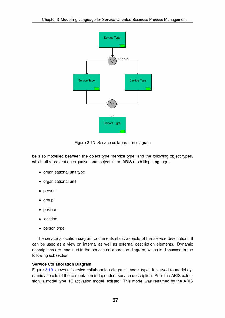
Chapter 3 Modelling Language for Service-Oriented Business Process Management
Service Type
Service Type Service Type
Service Type
activates
Figure 3.13: Service collaboration diagram
be also modelled between the object type “service type” and the following object types,which all represent an organisational object in the ARIS modelling language:
• organisational unit type
• organisational unit
• person
• group
• position
• location
• person type
The service allocation diagram documents static aspects of the service description. Itcan be used as a view on internal as well as external description elements. Dynamicdescriptions are modelled in the service collaboration diagram, which is discussed in thefollowing subsection.
Service Collaboration DiagramFigure 3.13 shows a “service collaboration diagram” model type. It is used to model dy-namic aspects of the computation independent service description. Prior the ARIS exten-sion, a model type “IE activation model” existed. This model was renamed by the ARIS
67

Chapter 3 Modelling Language for Service-Oriented Business Process Management
extension. The service collaboration diagram provides various constructs to model thedynamic relationships between services and their environment. However, those modellingcapabilities already existed before and were not changed by the ARIS extension. Themodel type is still affected by the ARIS extension, because the “functional cluster” ob-ject type was renamed to “service type” and a new symbol type “business service” wasintroduced.
Service Support MatrixA service support matrix is used to model the spatial availability of a service. However,the service support matrix is not an own model type in the ARIS modelling language butinstead a specific feature of the ARIS software tools. The ARIS software tools allow cre-ating a matrix by assigning different object types as column and row headers. At the endof the chapter in section 3.7, an example of such a matrix is provided in figure 3.16. Itcan be seen that the service type defines the column header and the different locationsdefine the row headers. The cells contain all those realisations of the service type, whichare available at the location specified in the row header.
Time Based ModellingSimilar to the service support matrix, time based modelling is a specific feature of theARIS software tools, but it is not an own model type in the ARIS modelling language. Timebased modelling looks similar to a service support matrix. The column header is definedby the service type and each row represents a point in time or a time range. Each cellcontains all realisations of the service type, which are available at the time specified in therow header.
Event-driven Process Chain (EPC)Besides services using the different model types described in the previous paragraphs,services are also used in business process modelling. Therefore, it was necessary toextend the EPC notation. Figure 3.14 shows the possible connection types. It can beseen that “function” object types can be related to “service type” object types using the“supports” connection type. This modelling construct describes that the execution of thefunction is supported by the service type. An employee executing the business processcan look up the description of the service type to identify a service realisation or serviceprovider.
Another use case of service-oriented business process management aims at automat-ing all functions of a business process so that the business process itself can be executedon a process engine. Therefore, it is possible to relate “software service type” object typesand their operations (i. e. “software service operation type” object types) to functions in thebusiness process using the “supports” connection type. Here, it is important to note thatthe software service types represent services implemented through technology, but notspecifying which technology is used. This ensures that the business process models donot contain any platform specific details. This is important, because if technology changes,the business process models can be reused without changing them.
The relations shown in the EPC model in figure 3.14 can also be modelled in a “functionallocation diagram” model type. A function allocation diagram is assigned to a function in abusiness process model to move information in a separated view. This reduces the overall
68
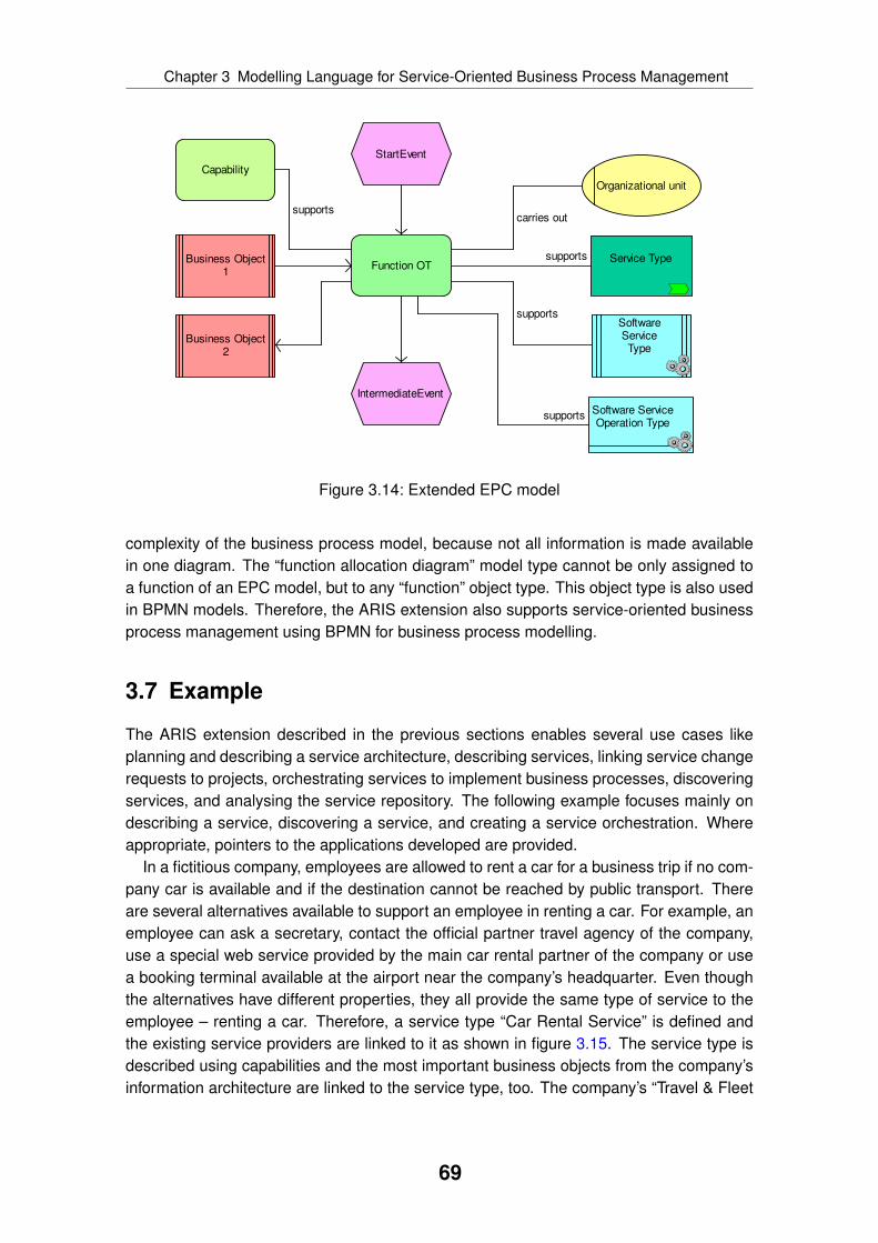
Chapter 3 Modelling Language for Service-Oriented Business Process Management
Service Type
StartEvent
Function OT
IntermediateEvent
supports
Capability
supports
Business Object1
Business Object2
SoftwareServiceType
Organizational unit
Software ServiceOperation Type
supports
carries out
supports
Figure 3.14: Extended EPC model
complexity of the business process model, because not all information is made availablein one diagram. The “function allocation diagram” model type cannot be only assigned toa function of an EPC model, but to any “function” object type. This object type is also usedin BPMN models. Therefore, the ARIS extension also supports service-oriented businessprocess management using BPMN for business process modelling.
3.7 Example
The ARIS extension described in the previous sections enables several use cases likeplanning and describing a service architecture, describing services, linking service changerequests to projects, orchestrating services to implement business processes, discoveringservices, and analysing the service repository. The following example focuses mainly ondescribing a service, discovering a service, and creating a service orchestration. Whereappropriate, pointers to the applications developed are provided.
In a fictitious company, employees are allowed to rent a car for a business trip if no com-pany car is available and if the destination cannot be reached by public transport. Thereare several alternatives available to support an employee in renting a car. For example, anemployee can ask a secretary, contact the official partner travel agency of the company,use a special web service provided by the main car rental partner of the company or usea booking terminal available at the airport near the company’s headquarter. Even thoughthe alternatives have different properties, they all provide the same type of service to theemployee – renting a car. Therefore, a service type “Car Rental Service” is defined andthe existing service providers are linked to it as shown in figure 3.15. The service type isdescribed using capabilities and the most important business objects from the company’sinformation architecture are linked to the service type, too. The company’s “Travel & Fleet
69

Chapter 3 Modelling Language for Service-Oriented Business Process Management
Legend:capability
bus. srv.
cluster
org. unit
soft. srv. type
appliance
Booking Terminal
Self Service Travel Management Fleet Management Booking
SecretaryCar Rental
Web ServiceTravel Agency
Travel & FleetManagementDepartment
realises
is input for
provides
Car Rental Service
provides
Travel Plan
Car RentContract
has output of
is owner of
Figure 3.15: Example service allocation diagram
Management Department” owns the service and is responsible for maintaining and devel-oping it. All this information is documented in a service allocation diagram as shown infigure 3.15.
The service support matrix shown in figure 3.16 models the spatial availability of theservice providers. The column headers contain the service types and the row headersthe locations. In the example, only the availability of the car rental service is modelled. Aservice realisation or provider is assigned to a cell if the service provider offers the speci-fied service type at the given location. Figure 3.16 shows that the “Car Rental Service” isavailable at the locations “Paris” and “London”. It also shows that in “London” the service isprovided by a “Secretary” and a web service. In addition to that, a “Booking Terminal” anda “Travel Agency” is available in “Paris”. The “Booking Terminal” denotes an appliance,which consists of hardware and software.
Service support matrix as well as service allocation diagram can be used for analy-sis. For example, redundancies in the service landscape can be identified or a differentprovider can be looked up in case a contracted service provider becomes unavailable. Theservice support matrix can be used to evaluate different scenarios like introducing a newrealisation at a location or de-supporting a realisation in the future. In chapter 4, an ap-plication is introduced, which provides automated support for service discovery based onthe content of the service allocation diagram.
Services can be used in business process models to document, which service supportsa function. Figure 3.17 shows a part of a business process model using the EPC notation.The function “Rent a Car” consumes the business object “Travel Plan” and produces thebusiness object “Car Rent Contract”. It is documented that a service is needed providingthe capabilities “Self Service” and “Travel Management”. Based on this information andthe information given in the service allocation diagram, it is possible to discover a ser-vice as shown in chapter 4. The service description becomes machine processable if the
70

Chapter 3 Modelling Language for Service-Oriented Business Process Management
Secretary
Secretary
Travel Agency
Car Rental
Web Service
Car Rental
Web ServiceBooking Terminal
Car Rental Service
London
Paris
Figure 3.16: Example service support matrix (spatial availability)
Car Rental Service
No CompanyCar Available
Car Rented
Rent a Car
Self Service Travel Management
needs
Travel Plan
Car RentContract
is input for
has output of
supports Legend:capability
bus. srv.
cluster
function
event
Figure 3.17: Snippet of example EPC process
service description is further formalised. An application using such a formalised servicedescription is described in chapter 7.
The business process model shown in figure 3.17 is used by an end user to decide,which service to use. If the business process is not automated but meant as a working in-struction, a user can use the information given in the service allocation diagram to evaluatethe different service providers. If all functions are supported by a software service imple-mented as a web service, the business process can be transformed into an executablemodel like BPEL. The automated EPC to BPEL transformation application is described inchapter 5. Another analysis is looking up all usages of a service type. This helps to esti-mate the impact of a proposed change and who is affected by a breakdown of a servicerealisation.
71

Chapter
4 Service Discovery
This chapter describes the first out of three applications based on the ARIS extension (seefigure 4.1). Service discovery aims at providing support in identifying services to be usedfor business process modelling. A motivation for developing this application is given insection 4.1. Section 4.2 describes the overall approach to service discovery and relates theapproach to the state of the art presentation in section 2.5. The following sections presentthe algorithms used in detail. Section 4.3 describes the structural matching algorithm andsection 4.4 introduces the semantic matching algorithm. Service assessment is supportedby a graphical user interface, which is presented in section 4.5. To illustrate the differentalgorithms, an example is provided in section 4.6.
4.1 Motivation
As it was shown in the state of the art presentation about business process automationin subsection 2.1.5, it is a common approach to use an orchestration of web services to
Algorithms &
Applications
Modelling
Method
Modelling
Technique
Modelling
Procedure
Modelling
LanguageService
DiscoveryEPC2BPEL
TransformationSemantic
BPM
Legend:
not covered in thesis
covered in thesis
Figure 4.1: Contribution service discovery application
72
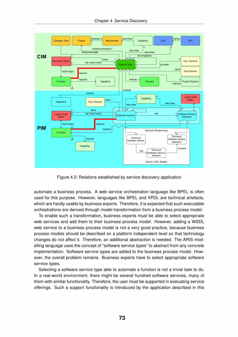
Chapter 4 Service Discovery
Logical DataObject
Function
Capability
Service Type
Process
Software Service
Appliance
n
describes
m
mhas input/outputn
SLA
n
describes
m
Business Object1owns
n
requires1
realises n
1
realisesn
1
encompassesn
Software ServiceOperation
Optional (Blueprinting)
Generic UML Models
TechnicalSoftware Service
TechnicalSoftware Service
Interface
TechnicalSoftware Service
Operation
Function
Capability
1 has n
n
supports
m
n
describes
mn
realises
1
containshas
n
describes
m
CIM
PIM
1
n
Business Object
1ownsn
nhas input/outputm
Capabilityrequires
Capability
requires
Logical DataObject
KPIdefines
Org. Elementn
provides1
Org. Elementowns
supports
Logical DataObject
Company Goal Project
influences/leads
created/extended in
Org Element
Product/Servicen
1
realises
input/output
input/output
owns
Requirementdescribesbelongs to
Figure 4.2: Relations established by service discovery application
automate a business process. A web service orchestration language like BPEL is oftenused for this purpose. However, languages like BPEL and XPDL are technical artefacts,which are hardly usable by business experts. Therefore, it is expected that such executableorchestrations are derived through model transformation from a business process model.
To enable such a transformation, business experts must be able to select appropriateweb services and add them to their business process model. However, adding a WSDLweb service to a business process model is not a very good practice, because businessprocess models should be described on a platform independent level so that technologychanges do not affect it. Therefore, an additional abstraction is needed. The ARIS mod-elling language uses the concept of “software service types” to abstract from any concreteimplementation. Software service types are added to the business process model. How-ever, the overall problem remains. Business experts have to select appropriate softwareservice types.
Selecting a software service type able to automate a function is not a trivial task to do.In a real-world environment, there might be several hundred software services, many ofthem with similar functionality. Therefore, the user must be supported in evaluating serviceofferings. Such a support functionality is introduced by the application described in this
73

Chapter 4 Service Discovery
chapter. The service discovery application helps to connect functions to software servicetypes or service types as visualised in figure 4.2.
The application provided aims at service discovery during design-time. The businessexpert is supported in selecting an appropriate service while modelling a business pro-cess. Service selection can also be done during runtime as shown in the state of the artpresentation on service discovery in section 2.5. An application supporting service dis-covery during runtime is presented in chapter 7. However, the case study presented inchapter 8 shows that currently business experts are not able to clearly motivate servicediscovery during runtime.
Even though the service discovery application supports the discovery of service typesas well as software service types, this chapter mainly focuses on the discovery of softwareservice types, because that is the more complex problem. Software service types areinternally mapped to implementations like WSDL web services and a discovery algorithmmust use the information provided by the WSDL description as well. This is not the casefor service types, because they are only described through capabilities and the businessobjects they consume and produce. The following section gives more details on the overallapproach taken.
4.2 Overall Approach to Service Discovery
The state of the art presentation in section 2.5 provided the following criteria to classifywork on service discovery:
• There are different approaches for service matching like structural, lexical, and se-mantic matching (see subsection 2.5.2).
• There are different strategies to combine the results of matching (see subsec-tion 2.5.3).
• Service discovery can be done during design-time and runtime (see subsec-tion 2.5.3).
• Service discovery applications differ in the way they implement the general servicediscovery process consisting of the main phases matching, assessment, and selec-tion (see subsection 2.5.4).
The previous section already discussed that the service discovery application focuseson service discovery during design-time. It is the aim of the application to support businessexperts in selecting appropriate services while they design business process models.
The service discovery application uses a structural and a lightweight semantic match-ing algorithm. A lexical matching algorithm is not used, even though the user can refinethe matching results during the assessment phase using ordinary string search. This isdiscussed in detail in section 4.5.
The structural matching algorithm discovers matching software service types byanalysing the data processed in the business process and the message formats supported
74

Chapter 4 Service Discovery
by the web services implementing the software service types. The structural matching al-gorithm is described in section 4.3.
The service discovery application also uses a lightweight semantic matching algorithm.It analyses the capabilities used in the service description and compares the availablecapabilities to the capabilities needed to automate the selected function. This algorithm iscalled only a lightweight semantic matching algorithm, because it does not use semanticweb technologies like reasoners and ontologies, but it still analyses the semantics of aservice. The algorithm is described in section 4.4.
The results of the structural and semantic matching algorithm are united following amixed strategy. A service is considered to fulfil the service discovery request if it is ei-ther discovered by structural or semantic matching or by both algorithms. Duplicates areremoved from the final result set before presenting it to the user for assessment.
The service discovery application is structured according to the three phases of the ser-vice discovery process. The user initiates the service discovery by selecting the functionto be related to a service (i. e. either to a service type or to a software service type). Duringthe first phase, the context of the selected function is analysed and the service request isderived. All services available in the ARIS software tools are compared against the ser-vice discovery request using the structural and lightweight semantic matching algorithms.In the second phase, the result set is presented to the user for assessment. In the thirdphase, the user selects the service to use and the service is added to the business processmodel relating it to the selected function. The overall behaviour of the service discoveryapplication does not differ for service types and software service types. The first phase ofthe service discovery process is automated, the other two phases are manual steps doneby the user.
The following subsections describe the different parts of the application in detail. Duringthe description, no specific user roles are mentioned to make the description not too com-plicated. An example is given in section 4.6. This example provides a walk-through alsodescribing the involved user roles.
4.3 Structural Matching Algorithm
The ARIS software tools support the WSDL standard version 1.1 [WSD01]. The contentof the WSDL file is represented in the ARIS modelling language using UML diagrams. Forexample, a WSDL porttype is mapped to an “UML interface” and the belonging operationsto “UML operations”. XSD files can be imported in the same way. The content of those filesis also represented using UML models. Those UML models are not meant to be used bybusiness experts. Therefore, an abstraction is introduced by using software service typesand software service operation types. Also, a business expert is not expected to deal withXSD data definitions. These data definitions are mapped to a logical data model, whichconsists of the object types “technical term”, “cluster”, “entity type” or “class”. The mappingbetween the different abstraction levels is established by relating the UML objects to themore abstract object types in different model types. The structural matching algorithmuses this mapping information to discover services by navigating from the logical dataconstructs used in the business process model to the technical constructs provided by
75

Chapter 4 Service Discovery
Function
Business
Object
Business
Object
Business
Object
Business
Object
… …
Input Output
Customer
B.O.
xsd:String
Abstract
Data Type (XSD)
Traverse Mapping Message
Type
Message
Type
Message
Type
Message
Type
Operation
ParameterOperation
ParameterOperation
ParameterOperation
Parameter
Match message types with operation parameters
(Input/Output)
Extract matching operation for each matched parameter
(Input/Output)
Operation
Operation
Operation
Operation
Get owning service
for each operation
1
23
45
Address
B.O.
OutputInput
ServiceService
Output
ServiceService
InputServiceService
Matching
Set
Compute intersection of matched input and output services
6
Figure 4.3: Structural service matching algorithm
the web service. The structural matching algorithm does not work if the mapping is notprovided by the user. Establishing this mapping is the task of creating an informationarchitecture1.
The structural matching algorithm for discovering software service types works as fol-lows: First, it extracts all business objects (i. e. either technical terms, clusters, entity typesor classes) modelled as input and output of the function (see step 1 in figure 4.3). Afterthis first step, there are two sets, one containing all business objects required as inputand the other one containing all business objects required as output. For each of thosetwo sets, the algorithm navigates through the data mapping to identify all message types.Implementing this navigation is not trivial, because the ARIS modelling language allowsarbitrary abstraction levels between business object and message type including cyclicdependencies. For example, the business object customer used in a business processis further decomposed into an address. This address can be represented using differentmessage types. The algorithm has to identify all message types mapped to the businessobject. This is illustrated between step 1 and 2 in figure 4.3. After this step, there are twosets of message types, one containing message types required as input and one contain-ing message types required as output. In step 3, the algorithm checks to which operationparameters those message types belong and if the parameters have the same direction asthe message types (i. e. input or output). Extracting this information is possible, becausethe complete WSDL content is available in the ARIS software tools and mapped to UML
1Other terms used for such an initiative are shared business vocabulary, business taxonomy or data archi-tecture.
76
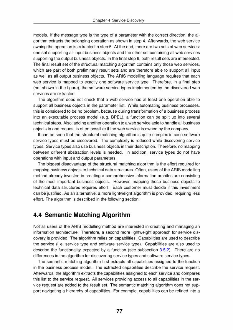
Chapter 4 Service Discovery
models. If the message type is the type of a parameter with the correct direction, the al-gorithm extracts the belonging operation as shown in step 4. Afterwards, the web serviceowning the operation is extracted in step 5. At the end, there are two sets of web services:one set supporting all input business objects and the other set containing all web servicessupporting the output business objects. In the final step 6, both result sets are intersected.The final result set of the structural matching algorithm contains only those web services,which are part of both preliminary result sets and are therefore able to support all inputas well as all output business objects. The ARIS modelling language requires that eachweb service is mapped to exactly one software service type. Therefore, in a final step(not shown in the figure), the software service types implemented by the discovered webservices are extracted.
The algorithm does not check that a web service has at least one operation able tosupport all business objects in the parameter list. While automating business processes,this is considered to be no problem, because during transformation of a business processinto an executable process model (e. g. BPEL), a function can be split up into severaltechnical steps. Also, adding another operation to a web service able to handle all businessobjects in one request is often possible if the web service is owned by the company.
It can be seen that the structural matching algorithm is quite complex in case softwareservice types must be discovered. The complexity is reduced while discovering servicetypes. Service types also use business objects in their description. Therefore, no mappingbetween different abstraction levels is needed. In addition, service types do not haveoperations with input and output parameters.
The biggest disadvantage of the structural matching algorithm is the effort required formapping business objects to technical data structures. Often, users of the ARIS modellingmethod already invested in creating a comprehensive information architecture consistingof the most important business objects. However, mapping those business objects totechnical data structures requires effort. Each customer must decide if this investmentcan be justified. As an alternative, a more lightweight algorithm is provided, requiring lesseffort. The algorithm is described in the following section.
4.4 Semantic Matching Algorithm
Not all users of the ARIS modelling method are interested in creating and managing aninformation architecture. Therefore, a second more lightweight approach for service dis-covery is provided. The algorithm relies on capabilities. Capabilities are used to describethe service (i. e. service type and software service type). Capabilities are also used todescribe the functionality expected by a function (see subsection 3.5.2). There are nodifferences in the algorithm for discovering service types and software service types.
The semantic matching algorithm first extracts all capabilities assigned to the functionin the business process model. The extracted capabilities describe the service request.Afterwards, the algorithm extracts the capabilities assigned to each service and comparesthis list to the service request. All services providing access to all capabilities in the ser-vice request are added to the result set. The semantic matching algorithm does not sup-port navigating a hierarchy of capabilities. For example, capabilities can be refined into a
77

Chapter 4 Service Discovery
Figure 4.4: Graphical user interface for service assessment
capability architecture using the model type “service architecture diagram” (see subsec-tion 3.6.4). This hierarchy is not considered in the semantic matching algorithm. A serviceis only discovered if it provides access to exactly those capabilities, which are specified inthe service discovery request.
4.5 Service Assessment and Refinement
The final result set consists of all services discovered either by the structural matchingalgorithm or by the semantic matching algorithm. The matching results are presented tothe user in a graphical user interface. A screenshot can be seen in figure 4.4. The screendesign consists of three parts, which are marked in the screenshot with the numbers 1–3.
During the assessment phase, the user further refines the result set. For example,
78

Chapter 4 Service Discovery
«wsdlService»
http://car-rental.com/webservice::CarRentalService
«interface»
«wsdlPortType»
http://car-rental.com/webservice::carRentalPT
+«wsdlOperation» checkAvailabilityOp(in inputPara: availabilityMsg, out outputPara: availabilityMsg)
+«wsdlOperation» rentCarOp(in inputPara: rentalMsg, out outputPara: rentalMsg)
«reside»
Figure 4.5: WSDL web service as UML component diagram
the user can search the descriptions and names of the services with a string search orhe can filter the list of services according to their namespace (only possible for softwareservice types). He can also filter the list according to the date the services were createdor imported into the ARIS software tools. Those refinement settings are done in part 1 ofthe screen design.
The current result set can be seen in part 2 of the screen design. This part also allowsswitching between a list of all services and the list with matching services. This is useful incase the matching algorithms did not return a satisfying discovery result.
The user has to assess if a service fulfils the service request. This assessment cannotbe done based on the name of a service. Therefore, additional information is shown in part3 of the screen design for the currently selected service. For example, all business objectssupported by the service are shown as well as the textual description. It is also possible tosee in which other contexts the service is used.
Finally, the user selects a service and confirms this selection. The dialog closes andthe service is automatically related to the function in the business process model. At thispoint, the application described in this chapter is complete.
4.6 Example
This section provides an example to better illustrate the service discovery application. Theexample mentions two different roles – a business expert and an IT architect. The businessexpert has no IT background, but instead experience in business process modelling. TheIT architect has SOA know-how and is able to use typical SOA middleware products andstandards. In reality, there are usually more roles involved. The example is aligned withthe example used in the previous chapter, which illustrated the use of the ARIS extension(see section 3.7).
A fictitious company defines an internal business process for organising business trips.If such a business trip has to be done by car, the employee has to use a company car ifavailable. Only if no company car is available, the employee is allowed to rent a car from adefined car rental company.
The car rental company provides a web service for this purpose. In order to be ableto use this web service in business process modelling, the web service is imported in the
79

Chapter 4 Service Discovery
CarRentalService
CarRentalService
encompasses
Web Interface
supports
Travel Management
Booking
Fleet Management
Partner Manager
Figure 4.6: Description of software service type (access diagram)
No CompanyCar Available
Rent a Car Car Rented
Web Interface Travel Management
Travel Plan
Car RentalContract
is input for
has output of
Figure 4.7: Business process without software service type
ARIS software tools. An IT architect imports the web service. The content of the WSDLfile is visualised as an UML component diagram as shown in figure 4.5.
Besides using this technical information, the IT architect abstracts from the web serviceby introducing a software service type for it. The software service type is described bythe IT architect using capabilities. The IT architect chooses between existing capabilities.The set of capabilities was defined in the past during an enterprise architecture modellingeffort. In addition, the IT architect might add who is responsible for this software servicetype. Figure 4.6 shows the description of the software service type. It has four capabilitiesand one owner.
If the company has an information architecture, the IT architect maps the message typesused by the web service to the belonging business objects. This can be a complex taskand he might have to consult the business expert to identify the correct business objects.The mapping is done in different diagrams, which are not shown.
A business expert models the business process described at the beginning of this sec-
80

Chapter 4 Service Discovery
CarRentalService
No CompanyCar Available
Rent a Car Car Rented
Web Interface Travel Management
Travel Plan
Car RentalContract
is input for
has output of
Figure 4.8: Business process with software service type
tion. Figure 4.7 shows a small part of the business process using the EPC notation. Thebusiness expert creates a function and connects it with the input and output businessobjects. In addition, the business expert specifies expected functionality by relating thefunction to capabilities. In reality, companies have either an information architecture or acapability architecture, but probably not both.
The business expert wants to automate the function using a software service type. Heselects the function and starts the service discovery application. The service discoveryapplication evaluates the content of the business process by extracting all input and outputbusiness objects and extracting the capabilities connected to the function. This informationis the input for the semantic and structural matching algorithms as described in the previ-ous sections. The results are shown to the business expert in the graphical user interfacediscussed in section 4.5. The business expert selects a software service type after as-sessing the different choices. The software service type is added to the business processas shown in figure 4.8. The symbol of the function is changed as well to visualise that thisfunction is now automated by a software service type.
The resulting business process cannot be executed directly, because different technicalinformation is still missing. An IT analyst uses the EPC to BPEL transformation applicationdescribed in the next chapter to generate a corresponding BPEL model. This BPEL modelmust be further refined, for example selecting correct web service operations or definingtechnical exception handling.
The example given in this section shows that a business expert is able to automatebusiness processes by discovering matching software service types. In order to select asoftware service type, the business expert does not need IT knowledge. In addition, an ITexpert implementing a business process receives a detailed specification for his work.
81

Chapter
5 Automated EPC toBPELTransformation
In order to bridge the business-IT divide, automated model transformations can be used.In case of business process automation, business process models are transformed intoexecutable models like EPC to BPEL. This thesis contributes such a transformation. Af-ter introducing the transformation in section 5.1, industrial requirements are extracted andcondensed in a general business to IT transformation framework (see section 5.2). After-wards, the chapter presents the different parts of the transformation application like thecontrol flow transformation in section 5.3, the data transformation in section 5.4, the ser-vice transformation in section 5.5, and the merge support in section 5.6. The EPC to BPELtransformation is one of three applications developed within this thesis (see figure 5.1).
5.1 Introduction
Business process automation, as described in subsection 2.1.5, aims as implementingbusiness processes through IT. In general, business process automation does not spec-
Algorithms &
Applications
Modelling
Method
Modelling
Technique
Modelling
Procedure
Modelling
LanguageService
DiscoveryEPC2BPEL
TransformationSemantic
BPM
Legend:
not covered in thesis
covered in thesis
Figure 5.1: Contribution EPC to BPEL process transformation application
82
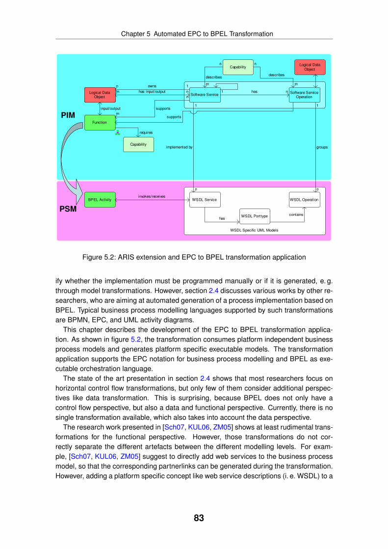
Chapter 5 Automated EPC to BPEL Transformation
Software ServiceSoftware Service
Operation
WSDL Specific UML Models
WSDL Service WSDL Operation
WSDL Porttype
Function
Capability
1 has n
1
groups
n
hascontains
BPEL Activity
n
supports
m
n
describes
m
invokes/receives
n
describes
m
PIM
PSM
1
n
implemented by
Business Object
1ownsn
nhas input/outputm
Capability
requires
Logical DataObject
supports
Logical Data
Object
input/output
Figure 5.2: ARIS extension and EPC to BPEL transformation application
ify whether the implementation must be programmed manually or if it is generated, e. g.through model transformations. However, section 2.4 discusses various works by other re-searchers, who are aiming at automated generation of a process implementation based onBPEL. Typical business process modelling languages supported by such transformationsare BPMN, EPC, and UML activity diagrams.
This chapter describes the development of the EPC to BPEL transformation applica-tion. As shown in figure 5.2, the transformation consumes platform independent businessprocess models and generates platform specific executable models. The transformationapplication supports the EPC notation for business process modelling and BPEL as exe-cutable orchestration language.
The state of the art presentation in section 2.4 shows that most researchers focus onhorizontal control flow transformations, but only few of them consider additional perspec-tives like data transformation. This is surprising, because BPEL does not only have acontrol flow perspective, but also a data and functional perspective. Currently, there is nosingle transformation available, which also takes into account the data perspective.
The research work presented in [Sch07, KUL06, ZM05] shows at least rudimental trans-formations for the functional perspective. However, those transformations do not cor-rectly separate the different artefacts between the different modelling levels. For exam-ple, [Sch07, KUL06, ZM05] suggest to directly add web services to the business processmodel, so that the corresponding partnerlinks can be generated during the transformation.However, adding a platform specific concept like web service descriptions (i. e. WSDL) to a
83
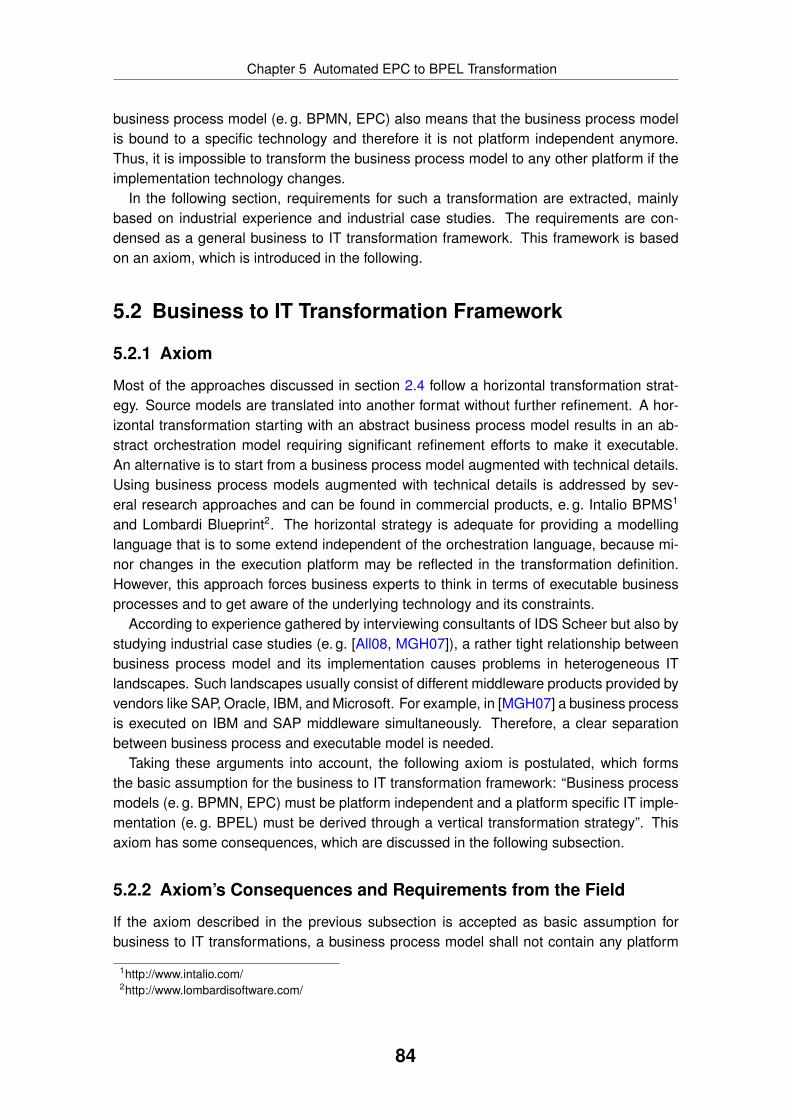
Chapter 5 Automated EPC to BPEL Transformation
business process model (e. g. BPMN, EPC) also means that the business process modelis bound to a specific technology and therefore it is not platform independent anymore.Thus, it is impossible to transform the business process model to any other platform if theimplementation technology changes.
In the following section, requirements for such a transformation are extracted, mainlybased on industrial experience and industrial case studies. The requirements are con-densed as a general business to IT transformation framework. This framework is basedon an axiom, which is introduced in the following.
5.2 Business to IT Transformation Framework
5.2.1 Axiom
Most of the approaches discussed in section 2.4 follow a horizontal transformation strat-egy. Source models are translated into another format without further refinement. A hor-izontal transformation starting with an abstract business process model results in an ab-stract orchestration model requiring significant refinement efforts to make it executable.An alternative is to start from a business process model augmented with technical details.Using business process models augmented with technical details is addressed by sev-eral research approaches and can be found in commercial products, e. g. Intalio BPMS1
and Lombardi Blueprint2. The horizontal strategy is adequate for providing a modellinglanguage that is to some extend independent of the orchestration language, because mi-nor changes in the execution platform may be reflected in the transformation definition.However, this approach forces business experts to think in terms of executable businessprocesses and to get aware of the underlying technology and its constraints.
According to experience gathered by interviewing consultants of IDS Scheer but also bystudying industrial case studies (e. g. [All08, MGH07]), a rather tight relationship betweenbusiness process model and its implementation causes problems in heterogeneous ITlandscapes. Such landscapes usually consist of different middleware products provided byvendors like SAP, Oracle, IBM, and Microsoft. For example, in [MGH07] a business processis executed on IBM and SAP middleware simultaneously. Therefore, a clear separationbetween business process and executable model is needed.
Taking these arguments into account, the following axiom is postulated, which formsthe basic assumption for the business to IT transformation framework: “Business processmodels (e. g. BPMN, EPC) must be platform independent and a platform specific IT imple-mentation (e. g. BPEL) must be derived through a vertical transformation strategy”. Thisaxiom has some consequences, which are discussed in the following subsection.
5.2.2 Axiom’s Consequences and Requirements from the Field
If the axiom described in the previous subsection is accepted as basic assumption forbusiness to IT transformations, a business process model shall not contain any platform
1http://www.intalio.com/2http://www.lombardisoftware.com/
84

Chapter 5 Automated EPC to BPEL Transformation
changed PIM
changed PSM
MERGE
top-d
ow
n
Figure 5.3: Concurrent changes resolved by means of merge functionality
specific details. This means, WSDL or SOAP descriptions shall not be added to the busi-ness process model, because even though WSDL and SOAP are standards supported bydifferent middleware products, they are still only one way to implement a SOA (see alsosubsection 2.2.2).
As platform specific details should not be added to the business process model, the exe-cutable model should be separated from it. This means, there is only one business processmodel, but there might be several implementations (1 : n). Each implementation can followanother paradigm. For example, a business process model can be implemented as a webservice orchestration, but also as an ordinary software application. This clear separationallows having a customised view on the business process – one view for business expertsand one view for implementation experts like software engineers.
Besides those consequences, there are also additional requirements from the field. Ac-cording to the experience gathered, it is possible and allowed to restrict the expressivenessof the source model language to a subset, which can be unambiguously transformed toan executable model. Obviously, this restriction should at least allow well-structured in-put models including cycles. Instead of supporting exotic control flow transformations, thebusiness expert should be guided according to clear modelling guidelines and supportedby validation functionality provided by the modelling tool.
In a vertical transformation strategy, it is necessary that the generated executable modelis further refined. Therefore, the generated executable model should be comprehensiblefor human users. For example, in case of BPEL only block elements should be usedignoring BPEL’s flow character. This is also demanded by [MLZ06, vdAL05].
As the generated model is usually changed manually after transformation, it must bepossible to have a link between business process model and executable model so thatusers can navigate easily between both worlds. If source and target model are availablein one tool, this is fairly easy to achieve, but if different tools are involved, some integrationbetween the tools is needed.
Transforming a business process model into an executable one is not a task done onlyonce [All08, see e. g.]. In contrast, business process models as well as BPEL models arechanged several times, also concurrent changes might happen. To resolve such concur-rent changes, a merge functionality is needed. A transformation algorithm must providesupport for merging concurrent changes like automatically resolving all conflicts or pre-senting conflicts to the user for manual resolution. This is visualised in figure 5.3.
85

Chapter 5 Automated EPC to BPEL Transformation
Business Objects
XSD Data
Definitions
Business Process
Control Flow
Executable Process
Control Flow
Supporting Application
Systems
Invoked Web
Services
Process
Perspective
Data
Perspective
Functional
Perspective
PIM
(BPMN, EPC)
PSM
(BPEL, WSDL,
XSD)
ver
tica
l tr
ansf
orm
atio
n
MERGE MERGE MERGE
Figure 5.4: Business to IT transformation framework
Finally, it is not enough to solely focus on a transformation of the control flow. As pointedout before, a transformation must take BPEL’s ability into account to represent data as wellas functions (services). In fact, transformation of the control flow is not the biggest chal-lenge from an industrial point of view [All08] and it is solved in many commercial softwareproducts already.
The next subsection develops a general framework for business to IT transformationstaking into account the requirements and the axiom’s consequences discussed in thissection.
5.2.3 Framework
Based on the requirements stated in the previous section and the axiom’s consequences,it is possible to formulate a general framework for business to IT transformations (see fig-ure 5.4). The framework refers to different modelling perspectives – process, data, andinteraction perspective – and thus reduces cognitive complexity at design-time. Further-more, figure 5.4 exemplifies some entities on two different levels of abstraction as wellas their relationships, which are operationalised by a vertical transformation. Manual re-finements in iterative development cycles are explicitly addressed by perspective-specificmerge functionalities.
The business to IT transformation framework does not designate a certain way of howthe transformation itself is implemented. For example, the control flow transformation mightbe completely automated whereas the data transformation might involve manual user in-teraction.
A transformation application not supporting all perspectives has only limited practicalapplicability. Therefore, the framework shown in figure 5.4 highlights that the intendedtransformation does not solely consist of a control flow transformation, but that also dataand interaction related aspects must be transformed. For example, a business processusually has a notion of data like business objects consumed and produced by functions.Those business objects must be present in the generated BPEL model as well, e. g. as
86

Chapter 5 Automated EPC to BPEL Transformation
input and output variables. The same is true for functional aspects. A business processmight specify which application system type supports which function. This informationmust be present in the generated BPEL model, e. g. as partnerlinks invoked by a BPELactivity.
The framework does not propose a particular way to implement the merge of differentmodel versions. At least, it must support model matching, change detection, change visu-alisation, and merge capabilities. Implementation details, e. g. the type of merge (2-way,3-way, 4-way), type of match (identity based, heuristic) or time of synchronisation, de-pend on the requirements of the specific usage scenario. Also, a transformation might usedifferent approaches for perspective specific merge functionality. There seems to be noneed at this point to have complete roundtrip support, so changes done in the generatedBPEL model should not be automatically propagated back to the business process model.Therefore, a business to IT transformation does not have to be bidirectional.
As the presented business to IT transformation framework incorporates real-world re-quirements, it ensures that transformations implementing it have a bigger practical impact.In the following sections, the EPC to BPEL transformation application is described in detail.The EPC to BPEL transformation application implements the framework developed in thissection.
5.3 Control Flow Transformation
The EPC to BPEL transformation application implements the business to IT transformationframework described in section 5.2. The belonging control flow transformation is describedin this section. The transformation application also provides support for transforming thedata perspective (see section 5.4) and the functional perspective (see section 5.5). It alsosupports merging as discussed in section 5.6.
The control flow transformation is based on a mapping of workflow patterns betweenEPC and BPEL. The 20 workflow patterns documented by Aalst et al. [vdAtHKB03] de-scribe common constructs like sequences, decisions, and loops found in many workflowlanguages. Those constructs can be combined with each other to build more complexcontrol flows. The analysis done by Wohed et al. [WvdADtH02] shows that BPEL does notsupport all workflow patterns. Another analysis by Mendling et al. [MNN05] shows similarresults for EPC. The compilation of both studies is shown in table 5.1.
Table 5.1 shows that BPEL supports all workflow patterns also supported by EPC exceptfor workflow pattern number 10. Workflow pattern number 10 describes arbitrary cycles.Aalst et al. [vdAtHKB03] explain that arbitrary cycles can be converted into structuredcycles if there is no advanced workflow pattern used in the cycle itself. As EPC do notsupport the advanced workflow patterns like workflow pattern number 14, this requirementis fulfilled and the cycles can be mapped in most cases to a BPEL while activity. Thetransformation restricts the EPC notation to further prevent modelling such constructs. Forexample, the transformation only supports EPC models using the XOR or AND operator.In addition, a branch must be joined with the same operator it was opened with and thenesting of the operators must be correct without intersections. Those restrictions do notallow the modelling of workflow pattern 6 and 7. The restrictions lead to structured EPC
87
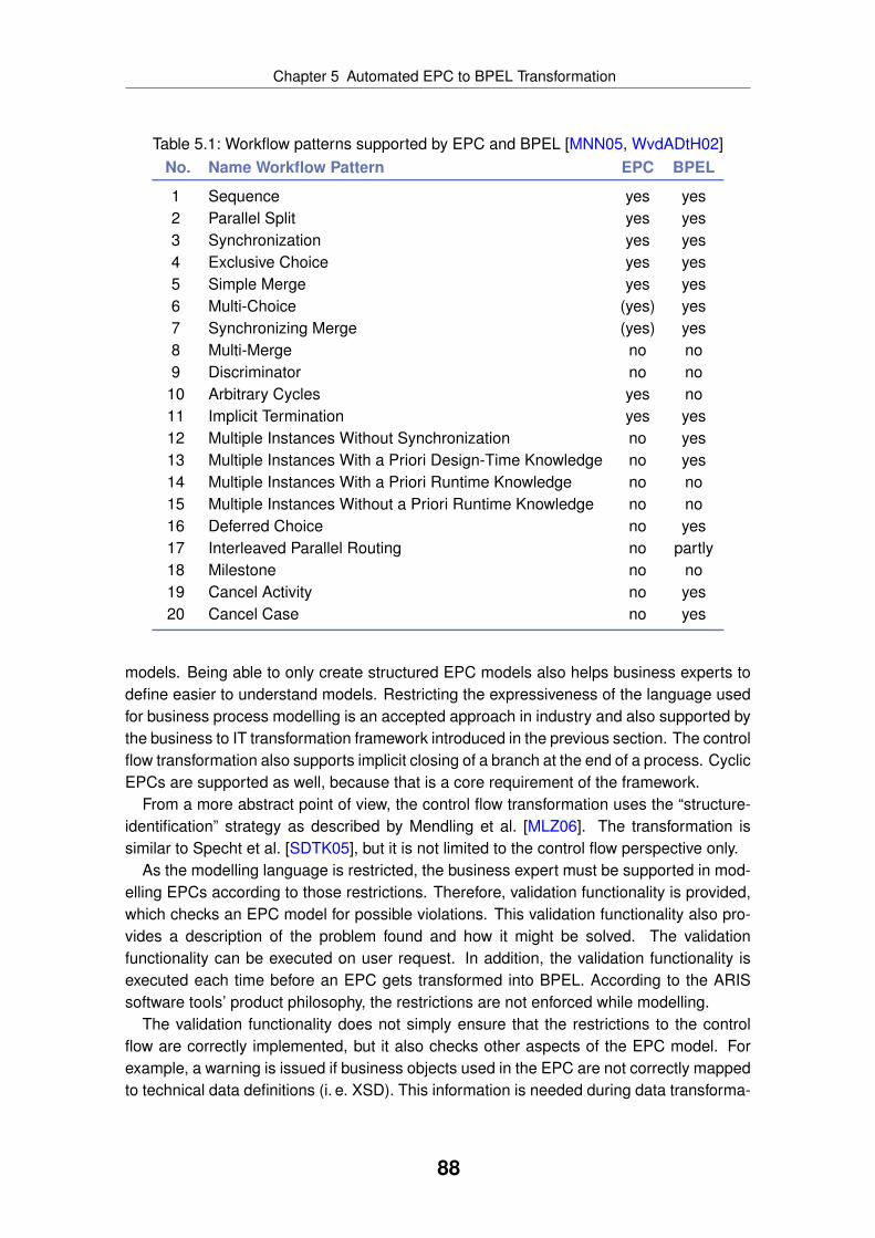
Chapter 5 Automated EPC to BPEL Transformation
Table 5.1: Workflow patterns supported by EPC and BPEL [MNN05, WvdADtH02]No. Name Workflow Pattern EPC BPEL
1 Sequence yes yes2 Parallel Split yes yes3 Synchronization yes yes4 Exclusive Choice yes yes5 Simple Merge yes yes6 Multi-Choice (yes) yes7 Synchronizing Merge (yes) yes8 Multi-Merge no no9 Discriminator no no10 Arbitrary Cycles yes no11 Implicit Termination yes yes12 Multiple Instances Without Synchronization no yes13 Multiple Instances With a Priori Design-Time Knowledge no yes14 Multiple Instances With a Priori Runtime Knowledge no no15 Multiple Instances Without a Priori Runtime Knowledge no no16 Deferred Choice no yes17 Interleaved Parallel Routing no partly18 Milestone no no19 Cancel Activity no yes20 Cancel Case no yes
models. Being able to only create structured EPC models also helps business experts todefine easier to understand models. Restricting the expressiveness of the language usedfor business process modelling is an accepted approach in industry and also supported bythe business to IT transformation framework introduced in the previous section. The controlflow transformation also supports implicit closing of a branch at the end of a process. CyclicEPCs are supported as well, because that is a core requirement of the framework.
From a more abstract point of view, the control flow transformation uses the “structure-identification” strategy as described by Mendling et al. [MLZ06]. The transformation issimilar to Specht et al. [SDTK05], but it is not limited to the control flow perspective only.
As the modelling language is restricted, the business expert must be supported in mod-elling EPCs according to those restrictions. Therefore, validation functionality is provided,which checks an EPC model for possible violations. This validation functionality also pro-vides a description of the problem found and how it might be solved. The validationfunctionality can be executed on user request. In addition, the validation functionality isexecuted each time before an EPC gets transformed into BPEL. According to the ARISsoftware tools’ product philosophy, the restrictions are not enforced while modelling.
The validation functionality does not simply ensure that the restrictions to the controlflow are correctly implemented, but it also checks other aspects of the EPC model. Forexample, a warning is issued if business objects used in the EPC are not correctly mappedto technical data definitions (i. e. XSD). This information is needed during data transforma-
88

Chapter 5 Automated EPC to BPEL Transformation
tion to correctly generate the necessary BPEL variables and message types. The datatransformation is described in the following section.
5.4 Data Transformation
A business process model usually contains data elements detailing the data flow withinthe process. The ARIS modelling language allows relating a function to business objectsin an EPC. The business object is either consumed or produced by the function. Businessobjects are mapped to a logical data model like an entity relationship model or an UMLclass diagram. There are usually several implementations of a logical data model likespecific database schemas or XSDs in case of web services.
XML schema definitions (XSD) are represented in the ARIS modelling language usingUML models with a specific UML profile. The user has to map the business objects tothe logical data model, which itself is mapped to different implementations. This mappingis done before the transformation and is usually part of a different effort focusing on es-tablishing an information architecture. By using business objects in the business processmodel instead of using technical data descriptions, the EPC remains technology neutraland is not bound to any specific implementation platform. The mapping is evaluated duringthe transformation to identify for each business object the belonging data implementation.BPEL variables are created for each business object and the variables are added as inputand output to the generated BPEL activities like invoke, receive, and reply. The visualisa-tion of generated variables is shown in figure 5.5. Data transformation also occurs whilegenerating a service interface for the BPEL process itself. This is discussed in subsec-tion 5.5.3.
5.5 Functional Transformation
5.5.1 Transformation of Service Information
In the ARIS modelling language, a “function” object type of a business process can berelated to an “application system type” object type to model that the function is supportedor even automated by an IT functionality. An application system type is a logical repre-sentation, which can be mapped to different implementations like legacy software or webservices. In case it is mapped to a web service, the symbol type “software service type”is used for the “application system type” object type. This mapping between software ser-vice type and implementing web service is also visualised in the SOA meta model like thesnippet shown in figure 5.2 at the beginning of this chapter.
As in case of XSDs, WSDL web services are represented in the ARIS modelling lan-guage by mapping the WSDL description to UML models using a specific UML profile.The mapping between application system types and their implementations is done beforethe transformation, e. g. while importing a WSDL file into the ARIS software tools. By us-ing application system types in the EPC and mapping them to web services outside of thebusiness process, the EPC does not contain any platform specific details.
89

Chapter 5 Automated EPC to BPEL Transformation
E1
SYS
F1
E2
Service
DataObj 1
DataObj 2
PortTypeService
PartnerLink
OperationF1
DataObj 1 DataObj 2
Figure 5.5: Transformation of service information from EPC to BPEL
The mapping between application system types and web services is evaluated duringthe transformation to identify for each function the belonging web service. For each func-tion, a BPEL invoke or receive activity is generated. The BPEL activity generated dependson the data objects related to the function in the EPC. The default situation is generating aBPEL invoke activity. If the function produces only an output data object, it is mapped to aBPEL receive activity.
Details of the BPEL activity are not presented in the main BPEL diagram generated.Instead, a “BPEL allocation diagram” model type is assigned to each activity in the BPELprocess. In this model type, the correct porttype and partnerlink are generated. It isalso possible that the user selects a web service operation. In that case, the operation ismodelled in the BPEL allocation diagram, too. In addition, the partnerlink types are alsogenerated and modelled in a BPEL allocation diagram connected to the start element of
90

Chapter 5 Automated EPC to BPEL Transformation
the BPEL process. Those additional details fulfil the aim of generating an executable BPELmodel out of a business process description. An example of a BPEL allocation diagram isshown at the bottom of figure 5.5. This figure also shows how variables are visualised inthe generated BPEL model.
BPEL supports synchronous as well as asynchronous process design. The followingsubsection describes how the transformation application supports those two different fla-vors of BPEL.
5.5.2 Synchronous and Asynchronous BPEL Processes
BPEL supports synchronous and asynchronous processes. If an external entity calls asynchronous BPEL process, the external entity waits for the answer of the BPEL processand is blocked for this period of time. In an asynchronous call, the external entity does notwait but instead the BPEL process invokes the external entity to call back. A synchronousBPEL process starts with a BPEL receive activity and ends with a BPEL reply activity. Anasynchronous BPEL process starts with a BPEL receive activity, but ends with a BPELinvoke activity.
EPCs can be transformed to synchronous as well as asynchronous processes. Theuser of the transformation application specifies if he wants to generate a synchronous orasynchronous process. However, in some cases the structure of the EPC already deter-mines what kind of BPEL process must be generated. For example, if an EPC has severalstart events merged with an AND or XOR operator, the EPC can be only transformed toan asynchronous BPEL process.
5.5.3 Service Interface Generation
Besides creating the BPEL constructs for the web services consumed, the transforma-tion application creates a WSDL description for the generated BPEL process itself. Thisweb service description is needed to invoke the BPEL process. The web service descrip-tion includes a complete partnerlink type with the belonging message types for the publicmessage exchange with the BPEL process.
Each BPEL process itself is also a web service, which can be invoked by other pro-cesses. By transforming a business process, the EPC can be reused as a web service. Inorder to reuse the business process as a web service, it must have an interface descriptionin WSDL. Therefore, the user can specify the target namespace and the name of the webservice to be generated. The transformation application generates the WSDL description,which can be exported as a file along with the BPEL file.
A service interface description does not only specify the operations of the service, butalso the input and output messages. Specifying those message types must also be possi-ble in EPC, otherwise reuse of the EPC as a web service is not possible. The transforma-tion application supports two different ways of modelling such a process interfaces. Bothways are illustrated in figure 5.6. The preferable way can be seen on the left side of thefigure. Here, the business objects are directly connected to the start and end event of theprocess. In the second, system functions named “Process Messaging Activity” are added
91

Chapter 5 Automated EPC to BPEL Transformation
IncomingMessage
OutgoingMessage
Start Event
End Event
F1
has state
has state
ProcessMessaging
Activity
Incoming
Message
Outgoing
Message
ProcessMessaging
Activity
Start Event
End Event
F1
is input for
has output of
a) b)
Figure 5.6: Implicit (a) and explicit (b) modelling of external message interface
directly after the start event and directly before the end event. The business objects areconnected to these system functions as shown on the right side of figure 5.6. The busi-ness objects are again mapped to technical data definitions (i. e. XSD). The transformationapplication evaluates this information to create the necessary data definitions for the webservice interface of the BPEL process.
5.5.4 Support for Proprietary BPEL Extensions
Even though BPEL is a public standard and supported by many different vendors, almostall vendors providing a BPEL execution engine have their own proprietary extensions.Typical examples are extensions for human tasks and business rules. The transformationapplication is meant to be vendor neutral by only creating standard BPEL and WSDL.It does not support such product specific BPEL extensions out of the box. However, incustomer projects support is needed. Therefore, the transformation can be extended.
If an EPC function is connected to an organisational element like an employee or or-ganisational role, a so called “extension activity” is added to the BPEL process as a place-holder. The user can extend this to export the human task in a format specific for theexecution engine used.
92

Chapter 5 Automated EPC to BPEL Transformation
merge
EPC EPC´
BPEL
BPEL´´
BPEL´
DiffBPELdiff update
BPEL´´´
manual change
automatic refinement automatic refinement
manual change
Figure 5.7: Merge support for EPC to BPEL transformation
5.6 Merge Support
The practical usage of a business to IT transformation requires that the user can run thetransformation several times without loosing manual changes already done on the targetIT model. This is a main requirement of the business to IT transformation frameworkintroduced in section 5.2.
The EPC to BPEL transformation application protects changes as depicted in figure 5.7.It is assumed that the user changes the business process model (e. g. adding a new func-tion) as well as the implementation model (e. g. some manual refinements). The manualchanges of the implementation model are computed on the base of a model differenceoperation that takes the original implementation model (BPEL) and the changed model(BPEL´´) as input. The difference model contains model changes and stores which ele-ments, attributes or relations are added, removed, and changed. The model differencesare added to the new implementation model (BPEL´), which results from the same auto-matic refinement operation as the original implementation model (BPEL). There can beconflicts arising from concurrent changes. For example, a function is removed while itscorresponding implementation function was changed or refined. In such cases, the mergefunction resolves conflicts according to a priority mode which determines whether changesin the business model dominate over changes in the implementation model or vice versa.The result of the merge operation is a new implementation model preserving most of themanual changes. The previously changed implementation model (BPEL´´) is not overwrit-ten by the merged implementation model (BPEL´´´) so that the user can review the mergeresult.
93

Chapter
6 Case Study:Model-DrivenBusiness ProcessAutomation
This thesis contains two case studies, which were conducted to evaluate the ARIS ex-tension and the applications developed. This chapter presents the first case study, whichevaluated the applications developed for business process automation. The introduction insection 6.1 specifies, which parts of the thesis’ contribution are evaluated and which previ-ous work is used. Section 6.2 provides some additional ideas about the research questiontackled by this case study. Afterwards, section 6.3 presents the real-world scenario usedin this case study and section 6.4 discusses how the case study was implemented. Finally,the results are presented in section 6.5. The case study was conducted within the publicresearch project OrViA1.
6.1 Introduction
The case study presented in this chapter was conducted to evaluate the following contri-butions made in this thesis:
• The ARIS modelling language together with the ARIS extension developed are cov-ered in this case study. The case study mainly focuses on the PIM and PSM level ofthe SOA meta model (see section 3.4).
• The service discovery application described in chapter 4 is evaluated, too. Servicediscovery is used to add software service types to a platform independent businessprocess model.
• The EPC to BPEL transformation application described in chapter 5 is used in thecase study to transform the annotated business process into an executable serviceorchestration.
1http://www.orvia.de/
94

Chapter 6 Case Study: Model-Driven Business Process Automation
Such an evaluation is necessary, because according to guidelines for design scienceresearch it is not enough to solely design new artefacts like the ARIS extension, but theartefacts must also be carefully evaluated [HMPR04]. See section 1.4 for a completediscussion on that topic.
The case study presented does not focus on a single artefact, but instead combines sev-eral of them to see how the artefacts interact and work together. For example, the servicediscovery application is needed to model a service-oriented business process model. Theannotation of the business process model is done based on the ARIS extension developedin this thesis. The service-oriented business process model is input for the EPC to BPELtransformation application to generate an executable business process model.
Besides artefacts developed in this thesis, the case study incorporates other works andtechniques, which were introduced in the state of the art chapter. The included techniquesare:
• The case study operates in the field of business process automation as discussedin subsection 2.1.5.
• The case study uses model transformations (see section 2.4) to automate a busi-ness process.
• More specifically, the case study follows model-driven integration engineering (seesection 2.3) for business process automation.
• The OrViA framework (see subsection 2.3.3) is used as guiding principle for model-driven integration engineering.
• Model checking techniques as discussed in subsection 2.3.4 are used in the casestudy, too.
This short overview of the included artefacts and techniques shows that the case studyis a complex one trying to explore the combination of a set of artefacts. The following sec-tion elaborates in detail on the research aim of this case study by formulating a hypothesis.
The case study presented in this chapter was done within the German research projectOrViA2. As such a research project is a collaborative effort, other researchers partic-ipated in it. The example business process was provided by the German company“Datenverarbeitungszentrum Mecklenburg-Vorpommern GmbH” [LRK06, KTRL07]. Thedomain specific extensions used to capture the example process are documented in[SDH06, DHW08]. The techniques for model validation are described in subsection 2.3.4and published in [FF08]. This collaborative effort is documented in several joined pub-lications [SKD+08, FFS08, SKI08]. The author of this thesis put together the differenttechniques and methods to form an integrated case study and the author performed theanalysis of the case study results.
2http://www.orvia.de/
95
Chapter 6 Case Study: Model-Driven Business Process Automation
6.2 Research Aim
The case study was conducted to investigate if model-driven integration engineering follow-ing the OrViA framework is possible and what problems exist. In order to prevent favouringthe OrViA framework by ignoring criticism, critical rationalism by Popper [Pop34] is appliedand the research question is turned around into the following hypothesis:
Hypothesis It is impossible to successfully use the OrViA framework as a guiding princi-ple for model-driven SOA implementations based on the ARIS modelling method.
To make the hypothesis operational, the application is considered to be “successful” iffewer budget is required, quality is improved, project length is shortened or a combinationof those three factors. Based on that hypothesis, the research question can be furtherrefined asking what is missing that it does not work, what shortcomings exist, where istool support missing, which parts of the OrViA framework are not integrated, what parts ofthe ARIS modelling language are not useful, and where is future research needed? Thisshows that the evaluation is explorative trying to draw overall conclusions, but not focusingon a single problem. The application of the different artefacts is explored based on anindustrial use case, which is described in the following section.
6.3 Scenario: Electronic Access to Register of Residents
The case study is conducted in the e-government domain, whereas “the term e-government focuses on the use of information and communication technologies (ICT) bygovernments applied to the full range of government functions” [Lau01, p. 2].
The real-world e-government scenario used in the case study is provided by the Ger-man company “Datenverarbeitungszentrum Mecklenburg-Vorpommern GmbH” (DVZ M-V3) [LRK06, KTRL07]. The company is based in Schwerin, Germany. DVZ M-V main-tains the IT systems of the public administration in the German region Mecklenburg-Vorpommern. They also support and implement new administrational processes.
DVZ M-V is responsible for the technical infrastructure and operation of the register ofresidents in Mecklenburg-Vorpommern. A German citizen must be registered at the placewhere he lives. Information about all residents of Mecklenburg-Vorpommern is stored inthe register of residents maintained by DVZ M-V.
The register of residents is used by public administration, companies, and individuals.For example, a company can use the register of residents to validate an address (e. g.address of an invoice to be issued). The register of residents is not a directory. Forexample, it is not possible to query all residents living in a certain street. The register ofresidents can only be used to validate an address. The access to the register of residentsis regulated by the law “Landesmeldegesetz Mecklenburg-Vorpommern”.
DVZ M-V provides electronic access to the register of residents. This service is offeredto interested parties through their web portal as a web service. The service is called“simple electronic access to the register of residents” (EARR). A visualisation of EARR
3http://www.dvz-mv.de/
96

Chapter 6 Case Study: Model-Driven Business Process Automation
Portal
WSDL
BPEL
EARR
Service
Service
Service
provided by DVZ M-V
Figure 6.1: Simple electronic access to register of residents (EARR) service
is shown in figure 6.1. The prerequisites and conditions under which EARR takes placeare defined by several legal regulations like the law “Landesmeldegesetz Mecklenburg-Vorpommern”.
Different public authorities take part in this service as service providers and service con-sumers, using different IT systems. For example, there are 100 different registration appli-cations by six different vendors used in the region Mecklenburg-Vorpommern. To ensureinteroperability between these systems, standardisation is needed. In the field of Germangovernmental registration services, the public “XMeld” standard4 defines the messages tobe exchanged between the different systems. The implementation of EARR must complywith those legal regulations and standards. Unfortunately, several versions of the XMeldstandard are available and must be supported by the EARR service simultaneously.
The process of validating an address and name of a single person with the registerof residents starts with an incoming XMeld message describing the validation request.Next, it is checked if the request can be answered complying with legal regulations likedata protection. If this is the case, access is granted and the responsible IT system isdetermined, i. e. the register containing the requested data. For example, if the personis not living in the German region Mecklenburg-Vorpommern, the request is forwarded toIT systems of the corresponding region. This is done through a so called intermediaryservice. There are several IT systems in Mecklenburg-Vorpommern, because the registerof residents is organised peripherally. The request is forwarded to the designated systemand the system answers with another XMeld message. This answer is passed back to therequestor. Each request is documented.
Following the idea of a technical SOA as described in subsection 2.2.2, all describedtasks are executed by a business process execution engine invoking several WSDL webservices. As the tasks are orchestrated in the shape of a BPEL process, the entire processcan easily be reused as a service in more complex settings. For example, the EARR
4http://www.osci.de/xmeld132a/xmeld-132a.zipversion1.3.2a
97
Chapter 6 Case Study: Model-Driven Business Process Automation
service can be used to validate a list of persons and addresses instead of creating a singlerequest for each person address pair.
Before this case study was conducted, DVZ M-V already implemented the EARR ser-vice manually. The implementation used the BPEL execution engine Microsoft BizTalkServer and the BPEL orchestration was created with Microsoft Orchestration Designer.This previous experience allows comparing the usage of the OrViA framework and theARIS modelling language against a manual approach.
The following section describes what was done during the case study and how thedifferent elements of the OrViA were instantiated. Also, it is shown how the ARIS modellinglanguage and the two evaluated applications were used.
6.4 Case Study
6.4.1 Overview
According to the research question described in section 6.2, it is the aim to evaluate if andhow the OrViA framework can be used successfully as a guiding principle for a model-driven SOA implementation based on the ARIS modelling language. The case study im-plements the electronic access to the register of residents service as described in theprevious section. This section describes the case study and is structured according to thethree main building blocks of the OrViA framework, namely:
• structured requirements analysis (including the service discovery application)
• validation
• transformation (including the EPC to BPEL transformation application)
6.4.2 Structured Requirements Analysis
The previous manual implementation of the EARR service was directly modelled in BPELby DVZ M-V. This modelling resulted in a very complex model, because business detailsas well as technical details were mixed in one model. This model was platform specific(PSM) not allowing exchanging the underlying technology. The OrViA framework insteadrecommends to first do structured requirements analysis on a platform independent level(PIM) and to derive the platform specific level through model transformation and stepwiserefinement. This allows separating business and technical details.
To elicit the requirements, the domain experts of DVZ M-V were interviewed and therelevant laws and regulations were studied. After, a first version of the process model wascreated and reworked together with the domain experts of DVZ M-V in several workshops.Also, the lead developer, who created the previous implementation of EARR, was inter-viewed and the BPEL model he created was studied. The existing implementation gaveadditional insights so that doing the same mistakes again could be prevented. For exam-ple, in the manually created version the handling for different XMeld versions was directlyincluded in the BPEL process.
98
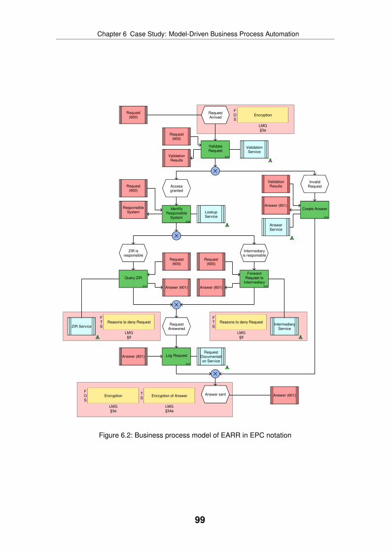
Chapter 6 Case Study: Model-Driven Business Process Automation
RequestArrived
Answer sent
Request(600)
ResponsibleSystem
Answer (601)
SYS
ValidateRequest
Accessgranted
InvalidRequest
SYS
IdentifyResponsible
System SYS
Create Answer
ZIR isresponsible
Intermediaryis responsible
SYS
Query ZIR
SYS
ForwardRequest to
Intermediary
Request(600)
ValidationResults
Request(600)
Request(600)
Request(600)
Answer (601) Answer (601)
Answer (601)
LookupService
AnswerService
ZIR ServiceIntermediary
Service
FOS
Encryption
LMG§3a
FOS
Encryption
LMG§3a
TS
Encryption of Answer
LMG§34a
FTS
Reasons to deny Request
LMG§9
FTS
Reasons to deny Request
LMG§9
ValidationResults
RequestAnswered
ValidationService
SYS
Log RequestAnswer (601)Request
Documentation Service
Figure 6.2: Business process model of EARR in EPC notation
99

Chapter 6 Case Study: Model-Driven Business Process Automation
Temporal Operators
All Globally
All Future
Figure 6.3: Example graphical validation rule for EARR process
To formally define the requirements, the ARIS modelling language was used. A ser-vice oriented business process model was created using the EPC notation. The ser-vice discovery application was used to assign a software service type to each function.The resulting model is shown in figure 6.2. The EPC notation was extended to alsocover domain-specific details like annotations with the corresponding laws and regulations[SDH06, DHW08]. This helps domain experts to easily navigate from the business processmodel to the belonging laws or regulations. The laws and regulations describe each stepin detail.
The resulting business process model is detailed enough to be transformed to BPELusing the EPC to BPEL transformation application. However, before the transformationwas done, first the model was validated. The OrViA framework demands the usage ofmodel validation to ensure that all informal requirements are correctly covered. The infor-mal and unstructured requirements are defined in the laws and regulations. The followingsubsection describes how validation was done.
6.4.3 Validation
The case study applied the model checking techniques introduced in subsection 2.3.4.First, the laws and regulations were analysed for possible rules. Afterwards, the rules weremodelled using G-CTL. For example, it is defined that each access to the register of resi-dents must be documented. This rule is shown in figure 6.3. In plain CTL, this rule is rep-resented by the follwoing expression: “AG(E_Access_granted -> AF(F_Log_Request))”. Itmeans that on every process path (“AG”) beginning from the event “Access granted” thefunction “Log Request” has to exist on all paths in the future (“AF”).
The G-CTL rules as well as the EPC model were exported in the ARIS software tools’proprietary AML format. To enable model checking, the content of the AML files wasconverted to the required format of the model checker SMV. The conversion was doneusing the operator hierarchy concept described in subsection 2.3.4. Computation of the
100
Chapter 6 Case Study: Model-Driven Business Process Automation
validation result by the model checker SMV took only a few microseconds. If a rule couldnot be validated, a counter example was given by the model checker.
To evaluate if G-CTL can be used by business experts, a modelling workshop with busi-ness experts was conducted. At the beginning, the G-CTL notation was introduced basedon some examples. Afterwards, the business experts were asked to formalise rules givenas textual description. In most cases, the business experts were able to create the correctG-CTL diagram.
6.4.4 Transformation and Execution
The validation showed that all requirements were formalised correctly. Also, the validationfunctionality of the EPC to BPEL transformation application issued no warnings or errors.Therefore, the EPC model was transformed into BPEL using the transformation applicationdescribed in chapter 5.
It was not possible to deploy directly the generated BPEL model, but instead somemanual refinements were needed like fixing the variable definitions and adding additionalnamespaces to the BPEL header. Still, no significant reworks were needed. The BPELprocess was deployed on the Oracle SOA Suite5. It was not possible to deploy the gen-erated model on Microsoft BizTalk, because BizTalk is not standard compliant. The webservices were not hosted on the Oracle server, because in reality they are not hosted onthe same machine either. The web services were deployed on the Java servlet containerApache Tomcat6. It was not possible to directly use the web services provided by DVZ M-V, because of data protection reasons. Therefore, a dummy implementation was createdfor the web services as well as for the end user portal7. This implementation followed theimplementation done by DVZ M-V.
6.5 Results
6.5.1 Case Study Domain
The previous section described how the OrViA framework was instantiated in the casestudy, where the two applications developed in this thesis were used, and where the ARISmodelling language extended in this thesis was applied. The case study was conductedto check if the hypothesis formulated in section 6.2 holds. The hypothesis postulates thatthe OrViA framework cannot be used as a guiding principle to do a model-driven SOAimplementation based on the ARIS modelling language. After conducting the case study,the author tends to slightly reject the hypothesis under the conditions discussed in thissection.
The case study was done with a use case from the e-government domain. Therefore,the hypothesis can only be rejected for the e-government domain if the selected use case
5http://www.oracle.com/technologies/soa/soa-suite.html6http://tomcat.apache.org/7https://service.mv-regierung.de/web/emrauser/emra
101
Chapter 6 Case Study: Model-Driven Business Process Automation
is representative for this domain. The author is confident that the use case is representa-tive for the e-government domain, because it was selected by a well-established use casepartner working in this domain. The use case partner tried in the past to implement thesame use case, but in contrast to the case study, the use case partner followed a manualapproach without using structured requirements analysis. The use case is directly imple-menting a public law and it involves different actors like the register of residents, gatewaysto other German regions, and an end user portal. As the use case implements the busi-ness process as it is defined by the law, the use case is not too simplistic but instead arealistic one. Even though only one case study was done in the e-government domain, thecurrently most important technologies were covered, because the used technologies wereselected by the use case partner already before the case study was conducted.
As the case study was only done for a use case in the e-government domain, additionaluse cases in other domains are required to see if the OrViA framework based on the ARISmodelling language can be applied there as well. Because of the limited time available toprepare this thesis, conducting additional case studies was not possible.
6.5.2 Structured Requirements Analysis
One important building block of the OrViA framework is structured requirements analysis.In order to be able to reject the hypothesis, the usefulness and applicability of it must beshown in case of the use case. The ARIS modelling language was used as a base forstructured requirements analysis. The process defined by the law was formalised usingthe EPC notation. To better represent the requirements, the standard EPC notation wasextended to cover domain-specific elements like clauses from the law. This approach ofcombining the advantages of a standard notation with a domain-specific language provedto be very successful. Using a standard notation has the advantage that it is supportedby commercial tools, which also provide the necessary transformations to follow a model-driven SOA implementation approach. On the other hand, extending such a standardnotation by domain-specific elements allows to better capture the domain and to adaptthe used language to the language used by the domain experts. This increases the com-prehensibility of the models for the domain experts and results in a higher acceptance bythem.
It was possible to model all aspects important for the SOA implementation and to laterderive the implementation through automated model transformation. During structuredrequirements analysis, the usage of the service discovery application was evaluated aswell. The service discovery application was able to suggest the correct services for eachprocess step. As no capabilities were used, only the structural matching algorithm wasused.
Additional benefits of doing structured requirements analysis were identified. For exam-ple, as the SOA implementation is directly derived from the business process model, theuse case partner can use the business process model for proving the compliance of the im-plementation with the law. This is possible, because structured requirements specificationand implementation are not mixed in a single BPEL model, but instead the implementationis derived out of the structured requirements specification through an automated transfor-
102

Chapter 6 Case Study: Model-Driven Business Process Automation
mation. Therefore, it is enough to check the structured requirements specification duringan audit in contrast to also checking the actual implementation.
6.5.3 Transformation and Execution
Another important element of the OrViA framework is the transformation used to derivethe IT implementation out of the structured requirements model. Here, the EPC to BPELtransformation application contributed by this thesis was used.
The author tends to reject the hypothesis in case of the transformation as well, butthere are a few more concerns to be discussed. It was possible to use the transforma-tion to create the BPEL model. The structure of the business process model as well asthe selected software services were correctly transformed into the corresponding BPELconstructs. This helps to speed up the implementation step, because creating all thoseconstructs manually requires much more effort and is an error-prone task. On the otherhand, the current transformation has some shortcomings, which result from bugs in thetransformation as well as conceptual problems. For example, transforming business ob-ject descriptions given in the business process model into data definitions (given as XSDs)is not working as expected. However, this was due to a bug in the transformation imple-mentation and not related to any fundamental conceptual problems in the approach. It waspossible to provide small scripts fixing the wrongly created data constructs.
A more pressing issue is related to the transformation of conditions in the control flowof the business process model. As BPEL is an executable language, the conditions forloops and branches must be defined with a strict syntax like XPath expressions. However,a business process model usually does not contain such formal expressions nor can it beexpected that a business expert is able or willing to create such expressions. This would bewrong from a conceptual view point, as well. XPath expressions are a concrete technologyand should therefore not be added to a platform independent model like the businessprocess model. Therefore, it must be investigated, how such conditions can be expressedin a technology independent way. A possible solution might be adding business rules tothe EPC, but this needs further investigations. Besides those problems discussed, it waspossible to deploy and execute the generated BPEL models without having to change alot.
6.5.4 Validation
The third core element of the OrViA framework is validation. According to the OrViA frame-work, validation should be applied to different artefacts like the business process model,the transformation rules, and the generated executable process model. During the casestudy, validation was not done on the transformation rules, because they are part of thetransformation application. Validation was used for the business process model. Basedon the law, a set of rules was created, which must be enforced like that each access tothe register of residents must be documented. Afterwards, the business process modelwas checked to see if it complies with the rules using model checking techniques. Froman algorithmic and technological standpoint, the author can confirm that validation works.
103

Chapter 6 Case Study: Model-Driven Business Process Automation
However, a more interesting question is whether the approach is feasible in real-worldprojects. The workshop with the business experts showed that they are able to formulatecorrect CTL expressions using the G-CTL notation.
Another important question is how the rules can be integrated with the process models.For example, it must be possible to reference a process model element like an event ora function in the rules. The current solution is not satisfying, because the dependencybetween rule and process model is too tight. If a rule specifies that a function must occurafter a certain event, the model checker will be only able to validate this rule if the functionand the event in the process model are named exactly as in the rule. If business expertsare allowed to freely name model elements while creating a business process model, thisis very unlikely to happen. Therefore, the vocabulary used for the model elements must bedefined and naming conventions must be enforced. At the current point, the author seesthis as a major problem.
The OrViA framework suggests validating the generated executable process model inorder to ensure that manual changes have not changed the semantics and that the ex-ecutable model is still implementing all business requirements. This validation step wasnot done in the case study, because the approach would have been similar to validatingthe business process model and the same limitations would apply. In summary, the authorrejects the hypothesis in case of validation, even though this is the most problematic part.
6.5.5 Tool Chain
The author does not consider it to be a threat to the validity of the study that only onespecific set of tools was used (mainly ARIS software tools, Oracle BPEL Process Server,and Apache Tomcat), because the focus was on evaluating if the OrViA framework can beapplied for such an implementation and not if it works with any kind of tool combination.However, it will be interesting to see if such a tool chain can also be built using OpenSource software or with other commercial products.
In general, the author found it challenging to integrate the different tools to form a com-plete tool chain, even though there are public standards like BPEL and WSDL. Makingthe top-down approach work is possible, but implementing a roundtrip scenario is almostimpossible. For example, if the BPEL model is changed in the ARIS software tools as wellas in Oracle JDeveloper, it is hard to merge those changes. The OrViA framework onlyprovides a top-down path with no backward links, because this makes the OrViA frame-work simple and easy to understand. On the other hand, it might be a too simplistic viewfor real-world projects, which is another point why the hypothesis is only slightly rejected.
6.5.6 Concluding Remarks
Besides the problems and limitations discussed above, there are also some clear advan-tages of applying the OrViA framework together with the ARIS modelling language. TheOrViA framework clearly divides the necessary tasks into packages. Each package re-quires specific skills like having profound business knowledge for structured requirementsanalysis or having software engineering skills for deployment and execution of the gener-
104

Chapter 6 Case Study: Model-Driven Business Process Automation
ated executable process model. This clear separation helps to reduce the overall com-plexity, because people only need a part of the overall required skill set to handle the partthey are assigned to. The complexity is further reduced by step-wise refinement. Eachstep only adds few aspects to the models and is therefore easier to handle. For exam-ple, during business process modelling, software services are discovered and selectedbut providing the correct binding information is done at a later step. This confirms the ad-vantage of having different abstraction levels as the ARIS modelling language extended inthis thesis does. It also shows that a vertical transformation is needed to convert betweenthe different abstraction levels.
The OrViA framework supports in providing different perspectives on the overall solution,which is another advantage and success factor for real-world projects. Another advantagelies in the fact that the OrViA framework is agnostic of the software engineering method-ology used. It does not matter if the project is done following the Waterfall model or usingan agile approach. This is an important fact, because companies usually have their ownmethodologies, which often cannot and should not be replaced. Therefore, being indepen-dent of a concrete methodology supports the adoption of the OrViA framework. On theother hand, the OrViA framework is conceptual and therefore it cannot be used out of thebox. Companies wishing to use the OrViA framework have to conduct a pilot project to seehow the framework must be tailored for their needs.
In summary, the author slightly rejects the hypothesis that the OrViA framework cannotbe used successfully as a guiding principle for model-driven SOA implementations basedon the ARIS modelling language. The two applications evaluated proved to be useful aswell.
105

Chapter
7 Semantic BusinessProcessManagement
The previous chapters introduced the extension added to the ARIS modelling languageand described two applications analysing the content captured with the ARIS modellinglanguage. This chapter introduces the third and final application (see figure 7.1) – semanticbusiness process management. This application combines the ARIS modelling languagewith semantic technologies to make the models machine processable. After motivatingthe use of semantics in section 7.1, the overall technical solution is outlined in section 7.2.The solution consists of two main parts: a semantically extended version of the ARISsoftware tools (see section 7.3) and a semantic execution environment (see section 7.4).The semantic business process management application is evaluated in the case studypresented in chapter 8.
The author of this thesis defined the overall architecture of the semantic business pro-cess management application and how the different components of it work together. Theactual software implementation was done in the diploma thesis [Sta08] supervised by theauthor.
Algorithms &
Applications
Modelling
Method
Modelling
Technique
Modelling
Procedure
Modelling
LanguageService
DiscoveryEPC2BPEL
TransformationSemantic
BPM
Legend:
not covered in thesis
covered in thesis
Figure 7.1: Contribution semantic business process management application
106
Chapter 7 Semantic Business Process Management
7.1 Motivation
The use of semantic technologies in business process management promises many ad-vantages. For example, semantic technologies like ontologies, reasoners, and mediatorscan be used to analyse an enterprise model like checking if the model complies with alaw or regulation. Additional advantages are discussed in the state of the art presenta-tion in section 2.6. In general, it is the aim of semantic business process managementto make the content of enterprise models accessible for machines. As discussed in sub-section 2.6.2, there are two main use cases supported by semantic business processmanagement:
1. Semantic technologies are used to analyse the content of an enterprise model.
2. Semantic technologies are used to derive new parts of an enterprise model.
So far, there is no empirical evaluation if the promised advantages can be achieved. Inaddition, it is not clear if semantic business process management can be integrated withexisting methods like the ARIS method. Therefore, this chapter presents a prototypicalapplication integrating semantic business process management with the ARIS method.The application only supports the first use case – analysing the enterprise model throughmachine reasoning. The application is used in the case study presented in chapter 8,where the actual empirical evaluation is done.
The application does not only enable evaluation of semantic business process manage-ment, but it also shows that the ARIS extension developed is flexible enough to be inte-grated with other approaches. For example, the ARIS extension introduces capabilities,but only textual descriptions are used to define their meaning. Semantic business processmanagement uses formal logical definitions to capture the capabilities of a system. It isthe challenge of this application to integrate both approaches.
The application also focuses on supporting business process automation like the EPCto BPEL transformation application described in chapter 5. In contrast to the EPC to BPELtransformation application, services used for automating the functions of the business pro-cess are not selected while modelling. Instead, only a semantic description is specifiedand service selection is done automatically during process execution. Therefore, the ap-plication described in this chapter consists of a semantic modelling environment and asemantic execution environment. The overall technical solution is described in the follow-ing section.
7.2 Solution Overview
The application contributes to the domain of business process automation. Semantic de-scriptions are used during process execution to discover and bind web services. The se-mantic descriptions are defined by business experts while modelling the business process.Therefore, the application consists of two parts:
1. The ARIS software tools are extended to allow semantic annotations of EPC processmodels. In addition, the EPC to BPEL transformation application is extended so that
107
Chapter 7 Semantic Business Process Management
the semantic annotations are preserved while generating the BPEL model. This partof the application is described in section 7.3.
2. Current BPEL execution engines are not able to evaluate semantic annotations.Therefore, a proxy service is provided, which takes care of semantic service dis-covery during process execution. It is described in section 7.4.
The following section describes in detail the changes done to the ARIS software toolsand the EPC to BPEL transformation application to enable semantic annotations.
7.3 Semantic ARIS Software Tools
7.3.1 Overview
The semantic modelling environment is based on the ARIS software tools. The follow-ing parts are added to the ARIS software tools to enable support for semantic businessprocess management:
• Semantic descriptions like WSMO goals can be loaded into the ARIS software tools.Therefore, the semantic descriptions must be represented by the ARIS modellinglanguage. This is described in subsection 7.3.2.
• Business experts must be able to annotate an EPC business process model withthe semantic descriptions. The belonging user interface concept is described insubsection 7.3.3.
• Semantic annotations also add ontological input and output instances to the busi-ness process model. Those instances must be combined to define a complete dataflow. The belonging tool is described in subsection 7.3.4.
• The EPC to BPEL transformation application must be extended to preserve the se-mantic annotations during process transformation. The implemented solution is de-scribed in subsection 7.3.5.
7.3.2 Representation of Semantics in ARIS
The semantic web community develops and supports different formalisms like OWL-S[MBH+04] and WSMO [FLP+06] (see also section 2.6). Therefore, the semantically ex-tended ARIS software tools must not be bound to a specific semantic formalism, but in-stead be as independent as possible. This means, the way semantic descriptions arerepresented by the ARIS modelling language must be the same for different semanticformalisms if possible. In an ideal case, this allows exchanging the semantic formalismwithout having to change the semantically annotated process models. Also, the user in-terface to select or create a semantic description must be identical, because the semanticformalism used does not matter for a business expert. The semantic business processmanagement application developed supports semantic annotations based on WSMO (see
108

Chapter 7 Semantic Business Process Management
Verify-Formal-Requirements
FormalVerification
customer::TP_Customer
formalVerification::FormalVerification
Figure 7.2: Function annotated with WSMO goal
subsection 2.6.3). Nevertheless, the general modelling principle used in the applicationcan be straightforwardly transferred to other formalisms like OWL-S.
Describing the functionality of (IT) systems is not a completely new approach and is usedin IT architecture management since several years. However, the semantic communityproposes a much more formal approach, which is harder to understand by people withno background in logic, mathematics or computer science, but which, on the other hand,is expressive enough to use automated reasoning. The ARIS modelling language usesthe “capability” object type to describe the functionality of systems. This object is used torepresent the semantic descriptions as well.
Figure 7.2 shows a part of an EPC process model with the function “Verify-Formal-Requirements”. In a complete EPC process model, this function would be related to otherfunctions or events (see subsection 2.1.4). The semantic description “Formal Verification”is represented by a “capability”, which is connected to the function. The “capability” wascreated by importing a WSMO goal description as described in the next subsection. Asthe semantic description is represented by a separate modelling object and not storedas an attribute value of the function, it can be reused to annotate different functions orIT systems. For example, if the semantic description is changed, only this object and itsattributes must be updated. All other objects like functions related to it will have the updatedsemantic description as well. This ensures that semantic descriptions stay consistent andit prevents redundancy, because each semantic description is only stored once in the ARISsoftware tools. Figure 7.2 also shows the ontological input/output instances defined by theWSMO goal. They are represented by a separate object and connected the function aswell. The following subsection shows the graphical user interface used to add semanticdescriptions to business process models.
7.3.3 Selecting a WSMO Goal in ARIS
Functions of an EPC process model can be annotated with semantic descriptions to de-scribe their functionality. In the semantic business process management application, the
109

Chapter 7 Semantic Business Process Management
Figure 7.3: GUI to select WSMO goal in ARIS software tools
annotation is supported by the graphical user interface shown in figure 7.3. The dialog isexecuted after selecting the function in the EPC, which should be annotated.
First, the user selects a folder on the local hard drive, where WSMO goal descriptionsas WSML files are stored. The dialog lists all files found in the selected folder on the leftside of the dialog. If the user clicks on an entry in the list, the content of the file is shownon the right side of the dialog. At this stage, the content of the WSML file is shown withoutany syntax highlighting or other visual support.
The user evaluates the applicability of a WSMO goal based on the WSML code. Finally,the user confirms the selection of a WSMO goal by clicking the “OK” button. A “capability”object type is created and automatically related to the function as shown in figure 7.2 anddiscussed before.
Another small support functionality is provided allowing to remove a semantic descrip-tion from a function, too. The dialog to select a WSMO goal and the support functionalityto remove a WSMO goal are implemented by the scripting language embedded in theARIS software tools. The scripts are available to the user and can be changed by them ifnecessary.
7.3.4 Completing the Data Flow
By selecting a WSMO goal to annotate a function, the WSMO goal and the ontologicalinput/output instances are added to the EPC. The ontological input/output instances mustbe mapped to define a complete data flow. This is illustrated in figure 7.4. A supportfunctionality is provided by the semantic business process management application todefine this mapping between ontological input/output instances. The user first selectsan output instance and afterwards the input instance. Now, the support functionality is
110
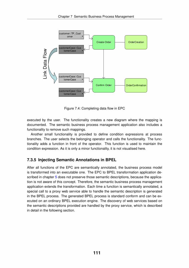
Chapter 7 Semantic Business Process Management
Create-Order
Confirm Order
OrderCreation
customer::TP_Cust
omer
customerCase::CustomerCase
OrderConfirmation
customerCase::Cus
tomerCase
customerCase::Cus
tomerCase
Lin
k D
ata
Flo
w
Figure 7.4: Completing data flow in EPC
executed by the user. The functionality creates a new diagram where the mapping isdocumented. The semantic business process management application also includes afunctionality to remove such mappings.
Another small functionality is provided to define condition expressions at processbranches. The user selects the belonging operator and calls the functionality. The func-tionality adds a function in front of the operator. This function is used to maintain thecondition expression. As it is only a minor functionality, it is not visualised here.
7.3.5 Injecting Semantic Annotations in BPEL
After all functions of the EPC are semantically annotated, the business process modelis transformed into an executable one. The EPC to BPEL transformation application de-scribed in chapter 5 does not preserve those semantic descriptions, because the applica-tion is not aware of this concept. Therefore, the semantic business process managementapplication extends the transformation. Each time a function is semantically annotated, aspecial call to a proxy web service able to handle the semantic description is generatedin the BPEL process. The generated BPEL process is standard conform and can be ex-ecuted on an ordinary BPEL execution engine. The discovery of web services based onthe semantic descriptions provided are handled by the proxy service, which is describedin detail in the following section.
111
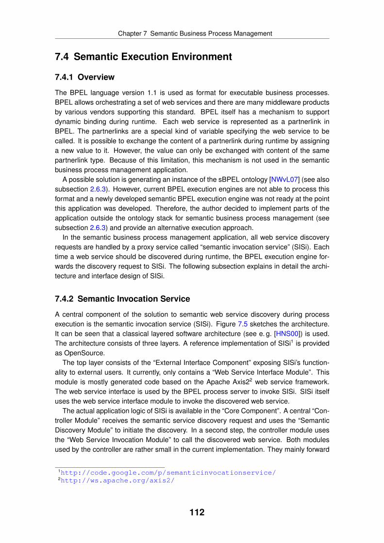
Chapter 7 Semantic Business Process Management
7.4 Semantic Execution Environment
7.4.1 Overview
The BPEL language version 1.1 is used as format for executable business processes.BPEL allows orchestrating a set of web services and there are many middleware productsby various vendors supporting this standard. BPEL itself has a mechanism to supportdynamic binding during runtime. Each web service is represented as a partnerlink inBPEL. The partnerlinks are a special kind of variable specifying the web service to becalled. It is possible to exchange the content of a partnerlink during runtime by assigninga new value to it. However, the value can only be exchanged with content of the samepartnerlink type. Because of this limitation, this mechanism is not used in the semanticbusiness process management application.
A possible solution is generating an instance of the sBPEL ontology [NWvL07] (see alsosubsection 2.6.3). However, current BPEL execution engines are not able to process thisformat and a newly developed semantic BPEL execution engine was not ready at the pointthis application was developed. Therefore, the author decided to implement parts of theapplication outside the ontology stack for semantic business process management (seesubsection 2.6.3) and provide an alternative execution approach.
In the semantic business process management application, all web service discoveryrequests are handled by a proxy service called “semantic invocation service” (SISi). Eachtime a web service should be discovered during runtime, the BPEL execution engine for-wards the discovery request to SISi. The following subsection explains in detail the archi-tecture and interface design of SISi.
7.4.2 Semantic Invocation Service
A central component of the solution to semantic web service discovery during processexecution is the semantic invocation service (SISi). Figure 7.5 sketches the architecture.It can be seen that a classical layered software architecture (see e. g. [HNS00]) is used.The architecture consists of three layers. A reference implementation of SISi1 is providedas OpenSource.
The top layer consists of the “External Interface Component” exposing SISi’s function-ality to external users. It currently, only contains a “Web Service Interface Module”. Thismodule is mostly generated code based on the Apache Axis22 web service framework.The web service interface is used by the BPEL process server to invoke SISi. SISi itselfuses the web service interface module to invoke the discovered web service.
The actual application logic of SISi is available in the “Core Component”. A central “Con-troller Module” receives the semantic service discovery request and uses the “SemanticDiscovery Module” to initiate the discovery. In a second step, the controller module usesthe “Web Service Invocation Module” to call the discovered web service. Both modulesused by the controller are rather small in the current implementation. They mainly forward
1http://code.google.com/p/semanticinvocationservice/2http://ws.apache.org/axis2/
112

Chapter 7 Semantic Business Process Management
Semantic Invocation Service (SISi)
Semantic Abstraction Component
Semantic Interface Factory Module
WSMX AdapterModule
IRS III AdapterModule
...
External Interface Component
Web Service Interface Module
Core Component
Semantic DiscoveryModule
Web Service InvocationModule
Controller Module
Semantic Abstraction Component
Semantic Interface Factory Module
WSMX AdapterModule
IRS III AdapterModule
...
Semantic Interface Factory Module
BPEL Process Server
WSMX IRS III ...
WSMX AdapterModule
IRS III AdapterModule
...
Semantic DiscoveryModule
Web Service InvocationModule
Discovered WebService
Controller Module
Web Service Interface Module
Figure 7.5: Software architecture of SISi
113

Chapter 7 Semantic Business Process Management
SemanticInvocation
Service (SISi)
SemanticDescription
Input Message
OutputMessage
Figure 7.6: Input consumed and output produced by SISi
the requests to the other components of SISi. The modules are included to ensure exten-sibility to fulfil future requirements. For example, if data mediation is needed in a futureversion, this can be added to the semantic discovery module without having to change thecontroller.
<?xml version="1.0" encoding="utf-8"?><wsdl:definitions name="WebServiceInterfaceWS"targetNamespace="http://sisi.externalInterface/"xmlns:wsdl="http://schemas.xmlsoap.org/wsdl/"xmlns:tns="http://sisi.externalInterface/"xmlns:dataNs="http://sisi.externalInterface/dataTypes"xmlns:xsd="http://www.w3.org/2001/XMLSchema"><wsdl:types><schema xmlns="http://www.w3.org/2001/XMLSchema"><import namespace="http://sisi.externalInterface/dataTypes"schemaLocation="SISi_WebServiceInterface_dataTypes.xsd"/>
</schema></wsdl:types><wsdl:message name="invokeSemanticWebServiceRequest"><wsdl:part name="semanticDescription" element="xsd:string"/><wsdl:part name="parameters" element="dataNs:hashMap"/>
</wsdl:message><wsdl:message name="invokeSemanticWebServiceResponse"><wsdl:part name="parameters" element="dataNs:hashMap"/>
</wsdl:message><wsdl:portType name="WebServiceInterfaceWS"><wsdl:operation name="invokeSemanticWebService"><wsdl:input message="invokeSemanticWebServiceRequest"/><wsdl:output message="invokeSemanticWebServiceResponse"/></wsdl:operation>
</wsdl:portType></wsdl:definitions>
Figure 7.7: WSDL definition of SISi
The bottom layer called “Semantic Abstraction Component” provides access to the se-mantic discovery components. Even though there are preliminary efforts3 to standardise
3http://www.oasis-open.org/committees/tc_home.php?wg_abbrev=semantic-ex
114

Chapter 7 Semantic Business Process Management
<xsd:schema xmlns:xsd="http://www.w3.org/2001/XMLSchema"xmlns:tns="http://sisi.externalInterface/dataTypes"><xsd:complexType name="hashMap"><xsd:complexContent><xsd:extension base="map"><xsd:sequence/>
</xsd:extension></xsd:complexContent>
</xsd:complexType><xsd:complexType name="map"><xsd:sequence><xsd:element name="mapEntry" type="mapEntry" minOccurs="0"maxOccurs="unbounded"/>
</xsd:sequence></xsd:complexType><xsd:complexType name="mapEntry"><xsd:sequence><xsd:element name="key" type="xsd:anyType"/><xsd:element name="value" type="xsd:anyType"/></xsd:sequence>
</xsd:complexType></xsd:schema>
Figure 7.8: Data definition of SISi
such components in a reference architecture, the author is not aware of any widely ac-cepted standard. Therefore, an individual adapter module is required for each seman-tic discovery component to be supported. The current implementation contains only anadapter module for WSMX [HCM+05]. All adapter modules must implement the same setof interface operations so that they can be used transparently through the “Semantic In-terface Factory Module”. This approach allows great flexibility, because any specifics ofthe different semantic discovery components to be supported are implemented in a singlemodule.
Figure 7.6 shows the input consumed and the output produced by SISi. In order toperform its task, SISi needs the semantic description like a WSMO goal and it needs theinput message for the web service to be invoked. As a result, SISi returns the message itreceived from the invoked web service. As SISi cannot foresee which web service will befound and invoked, it cannot provide an operation with parameters as the discovered webservice has.
The code snippet in figure 7.7 shows the WSDL definition of SISi and figure 7.8 showsthe belonging data definition of the different message parts. It can be seen that the in-put message consists of two parts – the semantic description and the message to beforwarded to the discovered web service. Currently, the type of the message part for thesemantic description is only a plain string. It is unknown what type is needed for the inputmessage of the discovered web service. Therefore, a hash map is used, which can con-tain objects of any type. The output message of SISi only consists of one message part.This message part transports the message received from the discovered and invoked web
115

Chapter 7 Semantic Business Process Management
Orchestration Engine
Web Service Engine
WS3WS2WS1...
SISi
1.
4.
3.
2.
Process1
Reasoner
5.
6.
Figure 7.9: System architecture for semantic process execution
service back to the calling BPEL process. Again, as the format of this message is notknown in advance, a hash map is used to store a collection of objects of any type.
7.4.3 Execution Principle
In order to execute the generated process, a special execution environment is needed, inwhich SISi is only one part. Additionally, the landscape includes an orchestration enginefor executing the generated BPEL process as well as a web service engine hosting theinvolved web services. Furthermore, also a semantic reasoner is needed for discoveringthe web services based on the given semantic descriptions. The overall system landscapeand the underlying execution principle can be found in figure 7.9. The execution of theBPEL process works as follows:
1. The BPEL process is executed on a standard orchestration engine. Whenever asemantically annotated function is found, the request is forwarded to SISi.
2. SISi receives the semantic discovery request. Besides the semantic description,SISi also takes the needed input parameters. SISi passes the semantic descriptionto the semantic reasoner.
3. The reasoner uses semantic discovery algorithms to find matching semantic webservice descriptions. The best fitting web service description is selected and passedback to SISi.
116

Chapter 7 Semantic Business Process Management
4. SISi uses the semantic web service description and finds through the includedgrounding information the underlying concrete web service implementation. Then,this web service is invoked with the input parameters received in the second step.
5. The web service is executed and the output data returned to SISi.
6. SISi forwards the output back to the BPEL process.
In the semantic business process management application, the system architecture isimplemented with the following software components:
• The semantically annotated BPEL process is executed on the Oracle BPEL ProcessServer4. The BPEL process definition includes invocations of SISi each time a webservice must be discovered during runtime.
• SISi itself is hosted on an instance of Apache Tomcat5.
• WSMX6 is used as semantic discovery environment. WSMX includes the necessaryreasoning components. WSMX also supports invoking the discovered web services.Therefore, WSMX is doing the actual invocation of the web services and passes theoutput message back to SISi. Step 4 and 5 are handled by WSMX as shown infigure 7.9.
• The web services are hosted on another instance of Apache Tomcat.
4http://www.oracle.com/lang/de/technologies/soa/soa-suite.html5http://tomcat.apache.org/6http://www.wsmx.org/
117

Chapter
8 Case Study:Semantic BusinessProcessManagement
This thesis uses case studies to evaluate the artefacts created. This chapter presents thesecond case study, which mainly focuses on evaluating the ARIS extension (see chapter 3)and the semantic business process management application (see chapter 7). This chapteris structured as follows: First, the motivation for this case study is presented in section 8.1.Afterwards, the research aim is presented in section 8.2. The scenario used in the casestudy is presented in section 8.3. The case study done is described in section 8.4 and theresults are presented and discussed at the end of this chapter in section 8.5.
8.1 Introduction
Semantic business process management as summarised in section 2.6 promises manyadvantages by enabling machines to process the content of enterprise models. Re-searchers aim at making semantic business process management a complete modellingmethod by working on specific modelling procedures, modelling languages, and applica-tions. However, as the evaluation of semantic business process management literature insubsection 2.6.6 shows, today no empirical studies are available to validate the usefulnessof it. In addition, semantic business process management is only expected to be suc-cessful if existing models (e. g. business process models) can be reused. So far, work onontologies built on top of existing modelling languages is provided, but a more integratedapproach is not available.
The present case study tackles both problems: providing empirical evaluation of seman-tic business process management and integrating it with an existing modelling method forbusiness process management. In context of the ARIS extension developed, the casestudy evaluates if the ARIS extension is flexible enough to be combined with a more for-malised approach. The case study presented is using the semantic business processmanagement application described in chapter 7. Also the EPC to BPEL transformationapplication is reused and extended as described in subsection 7.3.5.
The case study presented in this chapter was done within the European research project
118

Chapter 8 Case Study: Semantic Business Process Management
SUPER1. As such a research project is a collaborative effort, work done by the use-casepartner Telekomunikacja Polska [ESF+08, pp. 19] was reused. The business process ofthe use-case partner TP was converted into an EPC model and adapted to the needs ofthe case study. In addition, WSMO goals as described in [FRS07] were reused withoutany changes, too. Reusing this existing work ensured that the example process usedin the case study is a realistic one, which increases the validity of the case study. Thecollaboration between Telekomunikacja Polska and the author is documented in joinedpublications [SSEKR08, SSEKR09].
8.2 Research Aim
This case study aims at evaluating semantic business process management in an indus-trial setting. Therefore, the following research question is defined: “How does businessprocess management benefit from introducing semantic technologies and how is the adop-tion in industry of semantic business process management hindered?”
The research interests are of explorative nature. According to Yin [Yin03], controlledexperiments as well as case studies are research methods able to answer such “how” and“why” questions. Kitchenham et al. [KPP95] add that experiments are usually applied for“research-in-the-small” and case studies for “research-in-the-typical”. The research aimclearly focuses on research-in-the-typical, because it intends to investigate the usage ofsemantic business process management in a real-world setting. Kitchenham et al. alsostate that case study research is often used to evaluate new technologies. This also ap-plies for the research aim defined. To ensure that the research is conducted in an realisticenvironment, the existing ARIS method is used and extended to support semantic busi-ness process management as discussed in chapter 7. In addition, the case study is basedon a real-world use case, which is described in section 8.3.
The case study research follows the methodology defined by Yin [Yin03]. Yin’s method-ology is augmented with ideas taken from Kitchenham et al. [KPP95], because they de-scribe specific practices for case study research in software engineering, which are appli-cable here as well.
8.3 Scenario: VoIP Ordering Process of TelekomunikacjaPolska
The business process used in the semantic tutorial was contributed by TelekomunikacjaPolska2 (TP) [ESF+08, pp. 19]. Telekomunikacja Polska Group is the dominant player inthe Polish telecommunications market serving 10.6 million fixed-line subscribers and over12 million mobile customers, as of Q1/2007, employing about 28.000 people.
The voice-over-IP (VoIP) ordering business process is illustrated in figure 8.1 using theEPC notation. Most events and all semantic annotations were removed from the process
1http://www.ip-super.org/2http://www.tp.pl/
119

Chapter 8 Case Study: Semantic Business Process Management
Identify-Customer
Verify-Formal-Requirements
Customer-Confirms-Order
Prepare-Contract
Prepare-Hardware
Send-via-Courier-Service
Activate-VoIP-Platform
Archive-Contract
Activate-Billing
VoIP-Order-Request-Received
Verify-Technical-Requirements
Check-Customer-Deal-
for-Live-Box
VoIP-Order-Request-Finished
Create-Order Notify-Customer
Figure 8.1: VoIP ordering process at Telekomunikacja Polska
120

Chapter 8 Case Study: Semantic Business Process Management
model so that it fits on one page. The VoIP ordering process allows TP’s customers toorder the VoIP service for an existing contract. The ordering process is initiated by thecustomer through TP’s web portal. After identifying the customer, the process first checksif all technical and formal requirements are fulfilled. A new order is created, which must beconfirmed by the customer. A check is run to see if the customer already has the necessaryhardware. If not, the hardware is sent together with the contract to the customer. After TPreceives the signed contract, the contract is archived, the billing system is activated, andfinally the VoIP service is activated. Frankowski et al. [FRS07] provide a set of semanticdescriptions for the telecommunication domain, which were reused in the case study.
8.4 Case Study
8.4.1 Overview
The case study aims at evaluating semantic business process management in a real-worldsetting. The following elements contribute to this aim:
• The semantic business process management application is based on the ARISmethod, which is an accepted modelling method for business process management.
• The real-world scenario described in the previous section is used.
• Participants of the case study have an industrial background (see subsection 8.4.3).
During the case study, a tutorial and the semantic business process management ap-plication were provided to participants. The tutorial describes in a step-by-step instructionhow to use the application (see subsection 8.4.2). After conducting the tutorial, partici-pants were interviewed. The questionnaire and details about the interviews can be foundin subsection 8.4.4. The results of the case study are presented in section 8.5.
8.4.2 Semantic Tutorial
The tutorial describes the necessary steps to be conducted by the participants. This tu-torial is a written document and a modelling database for the ARIS software tools. Thetutorial starts with describing the domain ontology and the business process to be anno-tated semantically. Afterwards, it provides a step-by-step instruction to first annotate thebusiness process with WSMO goals, second to complete the data flow, third to transformthe business process into an executable one, and finally how the business process is exe-cuted. Each part of the tutorial is illustrated by one example. For example, it is explainedhow to annotate the first function in the business process. Annotating the remaining func-tions is the task of the participant and no further guidance is available in the tutorial. Thetutorial does not include any descriptions about semantics.
121

Chapter 8 Case Study: Semantic Business Process Management
Table 8.1: Participants of semantic business process management case studyType of Organisation Organisations Interviews Participants
Research Consulting Institute 2 2 3University 1 2 2University of Applied Sciences 2 4 4Company 3 5 8
Sum: 8 13 17
8.4.3 Participants
There are participants from different organisations. Table 8.1 shows the different typesof organisations, how many organisations of each type participated, how often the casestudy was done, and how many people took part. Research consulting institutes are re-search institutes, which are not solely financed through the public, but also offer commer-cial consulting services. A typical example is the German Fraunhofer institutes. The tabledistinguishes between university and university of applied sciences, because the latter onefocuses on practical application in contrast to theoretical education. None of the partici-pants was part of the research team and most of them had no prior knowledge of semantictechnologies. No additional material for background reading was provided to the partici-pants besides the semantic tutorial. The author paid special attention that the participantsdo not get aware of his own preconception of semantic business process managementand the case study propositions. The questionnaire used is discussed in the followingsubsection.
8.4.4 Questionnaire
After the participants conducted the tutorial, their experience was gathered through semi-structured interviews with 18 open-ended questions. The interviewees were asked to de-scribe what they have done, how non-semantic and semantic approach differ, and to reflecton the usage of semantics. At the beginning of each interview, the author elaborated onthe background of the research effort and explained that the interview results are madeanonymous and not publicly available assuring privacy. The author emphasised that heis not trying to prove or disprove semantics as beneficial. Participants were encouragedto ask questions. The interviews were not recorded but instead conducted by two re-searchers. One researcher led the interview and the other researcher focused on takingnotes. Each interviewer wrote a small summary immediately after the interview and bothsummaries were then exchanged. Work artefacts were collected like the semantically an-notated business process models. Some interviews were conducted as group interviewswith two or three participants. Therefore, there are a higher number of participants thaninterviews.
The questionnaire is shown below. Questions were rephrased if necessary. Also, ques-tions were skipped if the interviewee already provided an answer earlier during the inter-view.
122
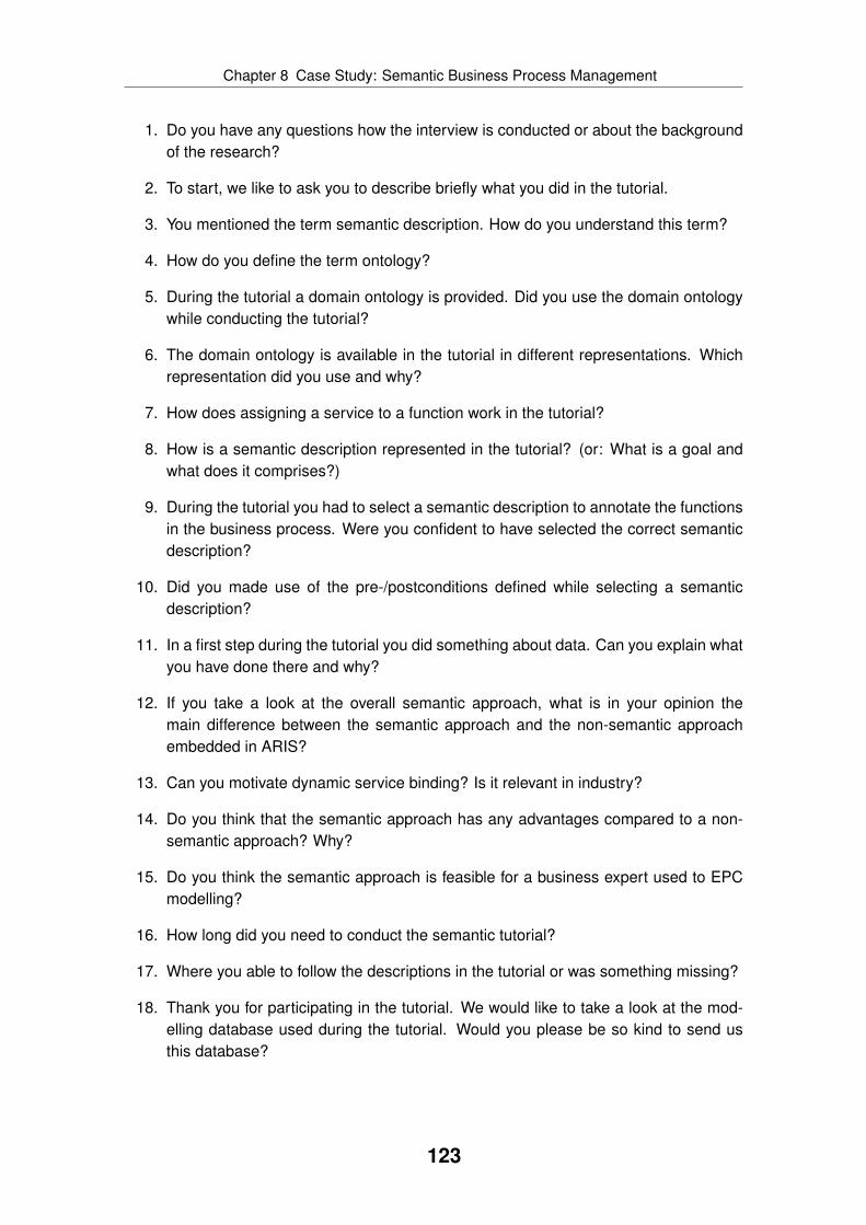
Chapter 8 Case Study: Semantic Business Process Management
1. Do you have any questions how the interview is conducted or about the backgroundof the research?
2. To start, we like to ask you to describe briefly what you did in the tutorial.
3. You mentioned the term semantic description. How do you understand this term?
4. How do you define the term ontology?
5. During the tutorial a domain ontology is provided. Did you use the domain ontologywhile conducting the tutorial?
6. The domain ontology is available in the tutorial in different representations. Whichrepresentation did you use and why?
7. How does assigning a service to a function work in the tutorial?
8. How is a semantic description represented in the tutorial? (or: What is a goal andwhat does it comprises?)
9. During the tutorial you had to select a semantic description to annotate the functionsin the business process. Were you confident to have selected the correct semanticdescription?
10. Did you made use of the pre-/postconditions defined while selecting a semanticdescription?
11. In a first step during the tutorial you did something about data. Can you explain whatyou have done there and why?
12. If you take a look at the overall semantic approach, what is in your opinion themain difference between the semantic approach and the non-semantic approachembedded in ARIS?
13. Can you motivate dynamic service binding? Is it relevant in industry?
14. Do you think that the semantic approach has any advantages compared to a non-semantic approach? Why?
15. Do you think the semantic approach is feasible for a business expert used to EPCmodelling?
16. How long did you need to conduct the semantic tutorial?
17. Where you able to follow the descriptions in the tutorial or was something missing?
18. Thank you for participating in the tutorial. We would like to take a look at the mod-elling database used during the tutorial. Would you please be so kind to send usthis database?
123

Chapter 8 Case Study: Semantic Business Process Management
8.5 Results
8.5.1 Overview
This section presents the case study results and a discussion of the outcomes. The resultsare not simply observed facts, but also a summary of the discussions with the participants.This section is structured around the main interview points. The answers between partici-pants from the different types of organisation were consistent if not discussed otherwise.
8.5.2 Understanding Semantics
At the beginning of each interview, participants were asked to summarise the differentsteps of the tutorial. Most participants were able to name the steps and their order. Dur-ing this summary, most of them used the word “semantic”. They were asked how theyunderstand semantics and how they define the term “ontology”.
All participants said a semantic description is not a technical one, but instead businessoriented. Interestingly, some of the participants said that a semantic description definesonly what needs to be done but not how to achieve it. None of the participants providedone of the popular definitions of ontology like “shared conceptualisation”. Instead, all par-ticipants tried to describe what an ontology is. Almost all participants pointed out thatan ontology is a collection of terms, concepts or classes. Some of them used the term“glossary” or “taxonomy”, but only a few called an ontology a “namespace”, a “domain”,a “classification” or a “domain specific language”. Some participants pointed out that anontology not only defines terms, but also relations between them. For example, one partic-ipant said an ontology describes “what exists and how everything is related to each other”and another said it is a “model of the world”. One participant pointed out that an ontologystandardises the vocabulary used. Interestingly, some participants also talked about “busi-ness cases” while actually referring to concepts. However, only a few pointed out that anontology is processable by machines.
None of the participants seemed to be comfortable with the term “ontology”, becausethe term is not known from daily language usage and seems artificial to them. The au-thor concludes to not use the term ontology while talking to business experts, but insteadtalk about “semantics” or “semantic descriptions”. To give a more detailed definition, oneshould talk about a glossary of business terms, which also has detailed relations betweenterms in contrast to ordinary glossaries. One should also point out that semantic descrip-tions of services are business oriented, processable by machines, and used to describewhat needs to be done, and not how it should be implemented.
8.5.3 Getting Familiar With the Domain
At the beginning of the semantic tutorial, the domain ontology developed by TP was pre-sented to the participants. All participants confirmed to have studied the domain ontologyat the beginning of the tutorial, but only a few of them used it later. The example processwas still simple enough and the terminology used was also known to the participants, whoproved to be experienced in business process management, because they were familiar
124

Chapter 8 Case Study: Semantic Business Process Management
with similar business processes. Many participants pointed out that it is unclear where thedomain ontology comes from and who creates it. The domain ontology was only availablein the printed tutorial, but it was not available in the ARIS software tools. This was con-fusing for some participants, because they expected the ontology to be present in the tool,too. Many of them pointed out that for more complex ontologies an “ontology browser” isrequired to allow easy navigation between the different concepts.
The author concludes that having a domain ontology is useful even if no other seman-tic technologies are used. Such an ontology must be available in the business processmodelling tool allowing easy usage and navigation.
8.5.4 Visualisation of Ontologies
The domain ontology was presented in three different ways to the participants: first a “star”of the main concepts generated by WSMO Studio, second a UML class diagram with aclass for each concept plus the belonging attributes and the main relations, and third theWSML code.
If participants were familiar with UML modelling like the participants not working in acompany, they found the UML class diagram most useful. Participants said that the UMLclass diagram contains far more information compared to the star diagram. If participantswere not familiar with UML, they preferred the star, because it provides an easy to under-stand overview of the domain ontology. All participants said the WSML code is not usefuland readable. Some of them noted that it might be possible to understand the WSML syn-tax after training, but that it is definitely not useful for business experts. One participatingbusiness expert confirmed that by saying he refuses to look at “something” like the WSMLcode.
The author concludes that a graphical representation along with a textual description ofa domain ontology is required. Probably several graphical representations are necessaryallowing the user to select the preferred one.
8.5.5 Selecting WSMO Goals
One important step of the tutorial was selecting a goal for each function using the graph-ical user interface described in subsection 7.3.3. It turned out that all participants identi-fied the name of the WSMO goal in the WSML code and based their decision mostly onthe name. Only a few of them looked at additional details of the goal description suchas pre-/postconditions. However, most participants recognised they must use the pre-/postconditions when goal selection is ambiguous.
Most participants were not satisfied with goal selection. Many pointed out that browsinga list of goals does not scale and more advanced search mechanisms are needed. Aparticipant suggested that it must be possible to filter the list of goals based on conceptstaken from the ontology. Another participant proposed using the pre-/postconditions asfilter criteria, e. g. only showing those goals able to produce a defined state. It was alsosuggested to add a graphical representation for each goal. One participant suggested the
125

Chapter 8 Case Study: Semantic Business Process Management
Preconditions
Postconditions
Goal NameC
apa
bilitie
sI/O
Data
Order ListConfirmation
Order List isCreated
Customer isIdentified
Confirm OrderList
Order Lis t
Order Lis t
Order List isConfirmed
Order List isPartly Confirmed
Order List is notConfirmed
Query Order List
Request Order
Confirmation
Figure 8.2: Participant contribution: graphical representation of WSMO goal
visualisation shown in figure 8.2. According to this participant, it is important to include thedifferent visual elements in the same place so that information can be identified quickly.
The author concludes that goal selection is an important part and must be supportedby a sophisticated tool. This requirement is amplified, because some participants pointedout that they cannot see any advantage compared to selecting a web service directly.Therefore, research should focus on ways to graphically visualise goals and semanticdescriptions.
8.5.6 Completing the Data Flow
After selecting a goal, participants completed the data flow by mapping ontological inputand output instances. Even though all participants were able to complete this step, someconcerns were raised. Participants pointed out that input/output instances are similar tovariables, whereas business objects are normally used in business process modelling. Ac-cording to participants, those two concepts are not interchangeable, because a businessobject is always persistent whereas a variable must be stored in a data store explicitly.This is an interesting point, which must be further investigated. It seems that ontologi-
126

Chapter 8 Case Study: Semantic Business Process Management
cal instances defined by WSMO goals are not abstract enough to be useful in businessprocess modelling.
8.5.7 Motivating Service Binding During Runtime
Participants were asked to motivate dynamic service binding during process execution.There was a diverse set of answers with no clear conclusion. Participants were explicitlyasked for an economic motivation. If they provided such a motivation, they often mentionedfailover scenarios. In the author’s opinion, this problem can be already solved today withenterprise service bus (ESB) platforms, but the participants were not confronted with thisopinion. Participants said that instead of hard coding an endpoint URL into the executableprocess, only the service name is added to the process. This helps in case the service ismoved to another server. Again, this seems to be a case where today’s technologies suchas service registries can be used.
Some participants noted dynamic service binding only makes sense if there are sev-eral services for each goal. If there is only a 1 : 1 relation between service and goal,participants were not able to justify dynamic service binding. Participants with researchbackground also pointed out that dynamic service binding in a company might not be asrelevant as e. g. in ubiquitous computing, because a company is able to better control andgovern the service architecture. Other participants mentioned dynamic service bindingis dangerous, because it adds a new error source and increases the complexity of theenterprise computing stack. This shows there is no consensus whether dynamic servicebinding is necessary in business process automation.
8.5.8 Advantages and Disadvantages of Semantic Approach
Participants were asked about advantages and disadvantages of the semantic approach.Surprisingly, most of them mentioned a better separation of business and IT as the mainadvantage of the semantic approach, because the business process model does not con-tain technical details. Instead, the business expert only specifies the required capabilities.This helps business experts to concentrate on the business part of process modelling in-stead of dealing with implementation details. It also allows using not yet existing services.In addition, technical service descriptions do not have to be available in the business pro-cess modelling tool, which prevents redundancy. Participants characterised the semanticapproach as creating a process template, which can be flexibly enacted, because thebusiness process model only specifies what has to be done but not how to do it. Someparticipants mentioned the possibility of dynamic service binding as an advantage, butthere was no consensus.
A significant problem is the conceptual mismatch between business objects and onto-logical input/output instances. Besides, several participants were not convinced that theinvestment in semantics can be justified economically, because ontologies must be definedand maintained. Some participants were reluctant about ontology modelling, becausein their opinion similar efforts such as establishing an enterprise information architecturefailed in the past. Such concerns are also raised by Hepp [Hep07] and must be taken
127

Chapter 8 Case Study: Semantic Business Process Management
into account. All participants agreed that business experts are not able to create ontolo-gies and goals. Graphical tools are required to overcome hurdles like WSML syntax andlogical expressions. Using semantics might require having ontology engineers, which is aspecific qualification. In general, the learning curve is increased, because semantics bringtheir own set of technologies, methods, and methodologies along. Also, the complexity ofthe enterprise computing stack is increased, which augments the probability of introducingerrors and integration problems. Many participants pointed to the unbalanced distributionof efforts and benefits for using semantics as another major disadvantage. Ontologies,goals, and semantic descriptions must be defined by IT after consulting business experts,but those artefacts mainly help business experts. This discrepancy must be carefully man-aged to ensure close cooperation between all involved parties.
8.5.9 Feasibility of Semantic Approach for Business Experts
Participants were asked whether the semantic approach is feasible for business experts.Most of them agreed that it is feasible, but they also mentioned potential problems. Cur-rently, technology is still too visible. For example, WSML code should not be shown andontological input/output instances must be lifted to a more abstract level. Ontologies andgoals used must exist upfront, because currently it is impossible for business experts todefine and modify them on their own. Besides the tooling issues, a solution must be foundto provide incentives to those who have to create the semantic descriptions.
Some participants were surprised that they were asked to annotate functions withsemantic descriptions. They believed that a business process model already containsenough information. Those participants envisioned a more advanced way of using seman-tics. For example, one participant desired to have a repository of semantically describedprocess fragments. Instead of defining the control flow of the business process, the par-ticipant expected to solely define the pre- and postconditions as well as constraints andthe control flow would be automatically created. This vision seems to be similar with whatvan der Aalst and Pesic [vdAP06] propose as Declarative Service Flow language. Insteadof defining a fixed control flow, the flow is declaratively defined allowing a more flexibleenactment. It will be interesting to see if such visionary approaches will gain momentum.
128

Chapter
9 Conclusions
This chapter summarises the work presented (see section 9.1), compares the work to theinitial theses (see section 9.2), and outlines future research activities (see section 9.3),which are planned to be done or which were already initiated.
9.1 Summary
This thesis aims at providing an integrated modelling method for service-oriented businessprocess management. Instead of designing a completely new modelling method, the ex-isting and established modelling method ARIS is reused. This thesis extends the ARISmodelling language so that services on different abstraction levels can be described. TheARIS extension is based on a comprehensive SOA meta model. In contrast to other works,the ARIS extension does not only cover the description of technical services, but also moreabstract services can be described. In addition, it is fully integrated with all other parts ofthe ARIS modelling method. This shows that SOA and business process managementcan be integrated and are not contradicting concepts.
Based on the ARIS extension, three applications are developed to operate on the modelcontent. The service discovery application helps business experts to evaluate serviceofferings and to select services for functions of a business process. The EPC to BPELtransformation application converts a business process annotated with software servicesinto an executable BPEL orchestration following a vertical transformation strategy. Thesemantic business process management application uses a formalised service descriptionand supports service discovery during process execution.
All artefacts created are evaluated in two empirical case studies to demonstrate theirrelevance and applicability. The first case study focuses on business process automationand covers the ARIS extension, the service discovery application, and the EPC to BPELtransformation application. The case study shows that business process automation ispossible and beneficial based on those artefacts. The second case study evaluates theARIS extension and the semantic business process management application. The results
129

Chapter 9 Conclusions
show that semantic business process management is a promising approach, but that thereare also several research challenges ahead.
The evaluation clearly demonstrates that the ARIS modelling method extension is able tomediate between the different perceptions of business process management and service-oriented architecture by providing an integrated modelling method.
9.2 Theses Fulfilment
Subsection 1.2.1 lists seven theses, which are expected to shape the work done in thisthesis. The first thesis describes that an integrated modelling method is required, whichdoes not solely focus on technical SOA artefacts. The modelling language introduced inchapter 3 and the applications and algorithms developed throughout this thesis confirmthis thesis. An integrated modelling method is created, which covers business as well astechnical aspects of a service-oriented enterprise architecture.
The structure of the modelling language introduced in chapter 3 also confirms the sec-ond thesis. The modelling language consists of several layers and features different no-tions of service concepts. For example, on the top layer a service type is introduced, whichcan be realised by a software service type on the platform independent layer.
Thesis three states that just relying on syntactical information like a programming inter-face description is not enough. This thesis is confirmed. The modelling language featuresdifferent modelling constructs to semantically describe a service, for example using capa-bilities. As shown in the case studies in chapter 6 and chapter 8, such modelling constructsare important enabling business experts to assess service offerings.
Thesis four postulates that algorithms or applications are needed to transform contentbetween different layers of the modelling language. Chapter 5 introduced one useful trans-formation, converting content on the platform independent layer to content on the platformspecific layer. The usefulness of such a transformation is confirmed in the case study inchapter 6.
To support business experts in selecting appropriate services in a specific modellingsituation, thesis five states that a supporting algorithm or application is needed. Such aservice discovery algorithm is described in chapter 4 and proved to be useful in the casestudy in chapter 6.
Thesis six states that the modelling language must be extensible. The application se-mantic business process management described in chapter 7 demonstrates the extensi-bility of the modelling language.
Finally, thesis seven postulates that the modelling method must be integrated with exist-ing modelling methods to ensure adoption in industry. The modelling method presented inthis thesis is integrated with and based on the modelling method ARIS, which is one of theleading modelling methods for enterprise architecture and business process managementin industry.
This overview shows that it was possible to confirm all theses stated at the beginning ofthis thesis in subsection 1.2.1.
130

Chapter 9 Conclusions
9.3 Future Work
The thesis touches many different areas and therefore many opportunities for future re-search exist. For example, the EPC to BPEL transformation application described in chap-ter 5 needs a more advanced data transformation algorithm. The current version doesnot generate the correct variable definitions under some circumstances. To improve thesituation, first work on this issue was already conducted in [CSR08]. In this work, a moreadvanced mapping between logical data objects and technical data definitions is used. Atransformation application can use this mapping to generate the corresponding data flow.
The thesis developed one application using semantic technologies to support businessprocess automation (see chapter 7). However, business process management is not lim-ited to business process automation and therefore additional applications of semantic tech-nologies in this domain are possible. In an early attempt, the author conducted a study toextract requirements for business process analysis. Those requirements document whatpractitioners try to achieve through business process analysis. One clear outcome is thatpractitioners are interested in compliance management, e. g. proving that they correctlyimplement a law or regulation. Therefore, in [EKSP08, EKSMP08b, EKSMP08a, EKS08]the usage of semantic technologies in compliance management is outlined. Laws andregulations are formalised as semantic policies, which must be enforced. On the otherhand, enterprise models are defined semantically, too. Both artefacts, semantic policiesand enterprise models, are consumed by a semantic inference engine to check whetherthe semantic enterprise model complies with the semantic policies. This approach is notlimited to enterprise models, but it can also be used to enforce policies during processexecution.
The service discovery application developed enables business experts to evaluate ser-vice offerings. However, the graphical user interface is still too complex and a much easierinterface is needed. A new concept for such an user interface was developed by the author.
The ARIS extension developed is currently used in first end user projects. Here, newrequirements emerge like providing a new model type to model value-chains consisting ofservice types. Those requirements are collected and carefully evaluated so that the ARISmodelling language covering SOA is further extended based on real-world requirements.In addition, the development of the belonging modelling procedure (see [Ric07, RP08])might create additional requirements, which must be supported by a future version of theARIS modelling language for service-oriented business process management.
This short overview of future work shows that the artefacts developed in this thesis arenot final, but that they will evolve as soon as the conditions and environment they werebuilt for changes. Also, new research findings will influence the design. The author willensure that the artefacts are maintained, enhanced, and extended if needed.
131

Bibliography
[AdMPvdA+07] A. K. Alves de Medeiros, C. Pedrinaci, W. M. P. van der Aalst,J. Domingue, M. Song, A. Rozinat, B. Norton, and L. Cabral. An out-look on semantic business process mining and monitoring. In On theMove to Meaningful Internet Systems 2007: OTM 2007 Workshops, vol-ume 4806 of LNCS, pages 1244–1255, Vilamoura, Portugal, November2007.
[AdMvdAP08] A. K. Alves de Medeiros, W. M. P. van der Aalst, and C. Pedrinaci. Se-mantic process mining tools: Core building blocks. In 16th EuropeanConference on Information Systems (ECIS), Galway, Ireland, 2008.
[AFKK07] W. Abramowicz, A. Filipowska, M. Kaczmarek, and T. Kaczmarek. Se-mantically enhanced business process modelling notation. In Work-shop on Semantic Business Process and Product Lifecycle Manage-ment (SBPM), volume 251 of CEUR Workshop Proceedings, pages 88–91, Innsbruck, Austria, June 2007.
[AFM+05] R. Akkiraju, J. Farrell, J. Miller, M. Nagarajan, M.-T. Schmidt, A. Sheth,and K. Verma. Web service semantics (wsdl-s) version 1.0. Technicalreport, W3 Consortium, November 2005.
[Alg07] J. Algermissen. Serviceorientierung mit rest. In G. Starke and S. Tilkov,editors, SOA-Expertenwissen – Praxis, Methoden und Konzepte ser-viceorientierter Architekturen, pages 777–804. dpunkt.verlag GmbH,Heidelberg, Germany, 2007.
[All06] T. Allweyer. Geschäftsprozessmanagement – Strategie, Entwurf, Imple-mentierung, Controlling. IT lernen. W3L GmbH, 2006.
[All07] T. Allweyer. Erzeugung detaillierter und ausführbarer geschäftsprozess-modelle durch modell-zu-modell-transformationen. In 6th GI Workshopon Event-Driven Process Chains (EPK), volume 303 of CEUR WorkshopProceedings, 2007.
[All08] T. Allweyer. Vom fachlichen modell zum ausführbaren workflow: Ambeispiel von aris und intalio bpms. Technical report, University of AppliedSciences Kaiserslautern, Kaiserslautern, Germany, February 2008.
132
Bibliography
[ARC04] Concepts for architectural description. Technical ReportTI/RS/2003/007, Telematica Institute, December 2004. ArchiMateDeliverable 2.2.1 v4.0.
[ARC06] Architecture language reference manual. Technical ReportTI/RS/2003/030, Telematica Institute, April 2006. ArchiMate Deliv-erable 2.2.2b v4.1.
[BHK+08] M. Born, J. Hoffmann, T. Kaczmarek, M. Kowalkiewicz, I. Markovic,J. Scicluna, I. Weber, and X. Zhou. Semantic annotation and compo-sition of business processes with maestro. In European Semantic WebConference (ESWC) Demo Track, June 2008.
[BKR05] J. Becker, M. Kugeler, and M. Rosemann, editors. Prozessmanage-ment: Ein Leitfaden zur prozessorientierten Organisationsgestaltung.Springer, Berlin, Germany, 5th edition, 2005.
[Ble07] M. Blechar. Magic quadrant for business process analysis market, 2h07.Technical report, Gartner, June 2007.
[BLHL01] T. Berners-Lee, J. Hendler, and O. Lassila. The semantic web. ScientificAmerican, 284(5):34–44, 2001.
[BPE03] Business process execution language for web services (bpel4ws) 1.1.Technical report, OASIS, May 2003.
[BPE07a] Web services business process execution language (bpel) version 2.0.Technical report, OASIS, April 2007.
[BPE07b] Ws-bpel extension for people (bpel4people), version 1.0. Technical re-port, June 2007.
[BS04] B. Bordbar and A. Staikopoulos. On behavioural model transformationin web services. In eCOMO – E-Business Processes and Infrastructure,volume 3289 of LNCS, 2004.
[CAdMZ+07] I. Celino, A. K. Alves de Medeiros, G. Zeissler, M. Oppitz, F. Facca, andS. Zöller. Semantic business process analysis. In Workshop on Se-mantic Business Process and Product Lifecycle Management (SBPM),volume 251 of CEUR Workshop Proceedings, pages 44–47, Innsbruck,Austria, June 2007.
[Car04] N. G. Carr. Does IT matter? Information Technology and the Corrosionof Competitive Advantage. Harvard Business School Press, 2004.
[CBD07] Cbdi service architecture and engineering (cbdi-sae). Technical report,Everware-CBDI Inc., 2007. Version 2.0.
133
Bibliography
[CD88] E. M. Clarke and I. A. Draghicescu. Expressibility results for linear-timeand branching-time logics. In Linear Time, Branching Time and Par-tial Order in Logics and Models for Concurrency, volume 354 of LNCS,pages 428–437, 1988.
[CE00] K. Czarnecki and U. W. Eisenecker. Generative Programming: Methods,Tools, and Applications. Addison-Wesley, 2000.
[CGP00] E. M. Clarke, O. Grumberg, and D. A. Peled. Model Checking. The MITPress, London, UK, January 2000.
[CHvRR04] L. Clement, A. Hately, C. von Riegen, and T. Rogers. Uddi version 3.0.2.Technical report, OASIS, October 2004.
[Cre02] J. W. Creswell. Research design: Qualitative, quantitative, and mixedmethod approaches. Sage Publications, Thousand Oaks, USA, 2nd edi-tion, 2002.
[CSR08] T. Conz, S. Stein, and C. Reck. Datentransformation im rahmender geschäftsprozessautomatisierung. In K.-P. Fähnrich, S. Kühne,and M. Thränert, editors, Model-Driven Integration Engineering, vol-ume XI of Leipziger Beiträge zur Informatik, pages 111–122. Eigenver-lag Leipziger Informatik-Verbund (LIV), Leipzig, Germany, September2008.
[Daw00] C. W. Dawson. The essence of computing projects: A student’s guide.Pearson Education Limited, Essex, UK, 2000.
[DCH+04] J. Domingue, L. Cabral, F. Hakimpour, D. Sell, and E. Motta. Irs iii: Aplatform and infrastructure for creating wsmo based semantic web ser-vices. In Workshop on WSMO Implementations (WIW2004), Frankfurt,Germany, 2004.
[Dem82] W. E. Deming. Out of the Crisis. MIT Press, 1982.
[DFK+07] J. Domingue, A. Filipowska, D. Karastoyanova, S. Stein, D. Roman, andM. Zaremba. Semantic BPM – The Integration of Business ProcessManagement and Semantic Web Services. Innsbruck, Austria, June2007. Tutorial at 4th European Semantic Web Conference (ESWC).
[dFMM+08] D. de Francisco, I. Markovic, J. Martinez, H. Munoz, and N. Perez.Methodological extensions for semantic business process modeling.In 10th International Conference on Enterprise Information Systems(ICEIS), Barcelona, Spain, June 2008.
[DHW08] J. Drawehn, O. Höß, and A. Weisbecker. Prozessbasierte anforderungs-analyse im kontext von serviceorientierten architekturen (soa). In K.-P.Fähnrich, S. Kühne, and M. Thränert, editors, Model-Driven Integration
134

Bibliography
Engineering, volume XI of Leipziger Beiträge zur Informatik, pages 51–60. Eigenverlag Leipziger Informatik-Verbund (LIV), Leipzig, Germany,September 2008.
[DSKM07] M. Dimitrov, A. Simov, M. Konstantinov, and V. Momtchev. Wsmo studio– a semantic web services modelling environment for wsmo (system de-scription). In 4th European Semantic Web Conference (ESWC), number4519 in LNCS, pages 749–758, Innsbruck, Austria, 2007.
[DSSK07] M. Dimitrov, A. Simov, S. Stein, and M. Konstantinov. A BPMO based se-mantic business process modelling environment. In M. Hepp, K. Hinkel-mann, D. Karagiannis, R. Klein, and N. Stojanovic, editors, Workshopon Semantic Business Process and Product Lifecycle Management(SBPM), volume 251 of CEUR Workshop Proceedings, pages 101–104,Innsbruck, Austria, June 2007.
[DvdA04] J. Dehnert and W. M. P. van der Aalst. Bridging the gap between busi-ness models and workflow specifications. International Journal of Co-operative Information Systems, 13(3):289–332, 2004.
[EKAdMSvdA08] M. El Kharbili, A. K. Alves de Medeiros, S. Stein, and W. M. P. van derAalst. Business process compliance checking: Current state and futurechallenges. In Modellierung betrieblicher Informationssysteme (MobIS),volume 141 of LNI, pages 107–113, Saarbrücken, Germany, November2008.
[EKS08] M. El Kharbili and S. Stein. Compliance management auf ba-sis von semantischen richtlinien. In K.-P. Fähnrich, S. Kühne, andM. Thränert, editors, Model-Driven Integration Engineering, volume XIof Leipziger Beiträge zur Informatik, pages 253–262. EigenverlagLeipziger Informatik-Verbund (LIV), Leipzig, Germany, September 2008.
[EKSMP08a] M. El Kharbili, S. Stein, I. Markovic, and E. Pulvermüller. Towards aframework for semantic business process compliance management. InThe Impact of Governance, Risk, and Compliance on Information Sys-tems (GRCIS), volume 339 of CEUR Workshop Proceedings, pages 1–15, Montpellier, France, June 2008.
[EKSMP08b] M. El Kharbili, S. Stein, I. Markovic, and E. Pulvermüller. Towards policy-powered semantic enterprise compliance management – discussion pa-per. In 3rd International Workshop on Semantic Business Process Man-agement (SBPM), CEUR Workshop Proceedings, Tenerife, Spain, June2008.
[EKSP08] M. El Kharbili, S. Stein, and E. Pulvermüller. Policy-based semanticcompliance checking for business process management. In Gemis-chter Workshop zu Referenzmodellierung und semantische Geschäft-
135

Bibliography
sprozessmodellierung, volume 420 of CEUR Workshop Proceedings,pages 178–192, Saarbrücken, Germany, November 2008.
[Erl05] T. Erl. Service-Oriented Architectures: Concepts, Technology, and De-sign. Prentice Hall, London, UK, September 2005.
[ESF+08] M. Evenson, B. Schreder, J. Frankowski, P. Rubach, and M. Skorczyk.Crm and billing prototypes, version 1.2. Technical Report Deliverable9.2, SUPER Research Project, November 2008.
[FBS+08] A. Filipowska, S. Bhiri, S. Stein, B. Norton, and M. Dimitrov. SemanticBusiness Process Management. Milan, Italy, September 2008. Tutorialat 6th International Conference on Business Process Management.
[Fel98] C. Fellbaum. WordNet: An Electronic Lexical Database. MIT Press,1998.
[FF08] S. Feja and D. Fötsch. Model checking with graphical validation rules.In 15th Annual IEEE Conference and Workshop on the Engineering ofComputer Based Systems (ECBS), pages 117–125. IEEE CS, 2008.
[FFS08] S. Feja, D. Fötsch, and S. Stein. Grafische validierungsregeln ambeispiel von epks. In Workshop Modellgetriebene Softwarearchitektur –Evolution, Integration und Migration (MSEIM), LNI, München, Germany,February 2008. GI.
[FGM+99] R. T. Fielding, J. Gettys, J. Mogul, H. Frystyk, L. Masinter, P. Leach, andT. Berners-Lee. Hypertext transfer protocol – http/1.1. Technical Report2616, W3 Consortium, June 1999.
[Fie00] R. T. Fielding. Architectural Styles and the Design of Network-basedSoftware Architectures. PhD thesis, University of California, Irvine, USA,2000.
[FK99] I. Foster and C. Kesselman, editors. The Grid: Blueprint for a new com-puting infrastructure. Morgan Kaufman, San Francisco, CA, USA, 1999.
[FKS08] A. Filipowska, M. Kaczmarek, and S. Stein. Semantically annotatedepc within semantic business process management. In Workshop onAdvances in Semantics for Web Services (semantics4ws), Milan, Italy,September 2008.
[FKSW06] K.-P. Fähnrich, S. Kühne, A. Speck, and J. Wagner, editors. OrViA– Integration betrieblicher Informationssysteme: Problemanalysen undLösungsansätze des Model-Driven Integration Engineering, volume IVof Leipziger Beiträge zur Informatik. Eigenverlag Leipziger Informatik-Verbund (LIV), Leipzig, Germany, 2006.
136

Bibliography
[FKT01] I. Foster, C. Kesselman, and S. Tuecke. The anatomy of the grid: En-abling scalable virtual organizations. International Journal of High Per-formance Computing Applications, 15(3):200–223, 2001.
[FKT08] K.-P. Fähnrich, S. Kühne, and M. Thränert, editors. Model-DrivenIntegration Engineering, volume XI of Leipziger Beiträge zur Infor-matik. Eigenverlag Leipziger Informatik-Verbund (LIV), Leipzig, Ger-many, September 2008.
[FL07] J. Farrell and H. Lausen. Semantic annotations for wsdl. Technicalreport, W3 Consortium, 2007.
[FLP+06] D. Fensel, H. Lausen, A. Polleres, J. de Bruijn, M. Stollberg, D. Roman,and J. Domingue. Enabling Semantic Web Services: The Web ServiceModeling Ontology. Springer, 2006.
[FNS05] S. Fuger, F. Najmi, and N. Stojanovic. ebxml registry information modelversion 3.0. Technical report, OASIS, May 2005.
[FP07] D. Fötsch and E. Pulvermüller. Constructing higher-level transformationlanguages based on xml. In 5th International Conference on SoftwareMethodologies, Tools and Techniques (SOMET), Rome, Italy, November2007. IOS Press.
[FRS07] J. Frankowski, P. Rubach, and E. Szczekocka. Collaborative ontologydevelopment in real telecom environment. In 1st International WorkingConference on Business Process and Services Computing (BPSC), vol-ume 116 of LNI, pages 40–53, Leipzig, Germany, September 2007.
[FS09] T. Feld and S. Stein. Soa - lessons from the battlefield. In InternationalSymposium on Service Science (ISSS), Leipzig, Germany, March 2009.
[FSH05] D. Fötsch, A. Speck, and P. Hänsgen. The operator hierarchy conceptfor xml document transformation technologies. In 3. Berliner XML-Tage2005 (BXML05), pages 59–70, Berlin, Germany, 2005.
[GHM+03] M. Gudgin, M. Hadley, N. Mendelsohn, J.-J. Moreau, and H. Frystyk.Soap version 1.2 part 1: Messaging framework. Technical report, W3Consortium, June 2003.
[GPFLC04] A. Gómez-Pérez, M. Fernández-López, and O. Corcho. Ontological En-gineering. Springer, London, UK, 2nd edition, 2004.
[Gru93] T. R. Gruber. A translation approach to portable ontologies. KnowledgeAcquisition, 5(2):199–220, 1993.
[GS04] J. Greenfield and K. Short. Software Factories: Assembling Applicationswith Patterns, Models, Frameworks, and Tools. Wiley, 2004.
137

Bibliography
[Ham90] M. Hammer. Reengineering work: Don’t automate, obliterate. HarvardBusiness Review, pages 104–112, July 1990.
[HCM+05] A. Haller, E. Cimpian, A. Mocan, E. Oren, and C. Bussler. Wsmx – asemantic service-oriented architecture. In International Conference onWeb Service (ICWS), Orlando, Florida, USA, 2005.
[Hep07] M. Hepp. Possible ontologies: How reality constrains the developmentof relevant ontologies. IEEE Internet Computing, 11(1):90–96, 2007.
[HHV06] A. Hess, B. Humm, and M. Voß. Regeln für serviceorientierte architek-turen hoher qualität. Informatik Spektrum, 29(6):395–411, 2006.
[HK04] R. Hauser and J. Koehler. Compiling process graphs into executablecode. In 3rd International Conference on Generative Programming andComponent Engineering (GPCE), volume 3286 of LNCS, pages 317–336, Vancouver, Canada, 2004.
[HLD+05] M. Hepp, F. Leymann, J. Domingue, A. Wahler, and D. Fensel. Seman-tic business process management: A vision towards using semantic webservices for business process management. In IEEE International Con-ference on e-Business Engineering (ICEBE), pages 535–540, Beijing,China, 2005.
[HMPR04] A. R. Hevner, S. T. March, J. Park, and S. Ram. Design science in infor-mation systems research. MIS Quarterly, 28(1):75–105, March 2004.
[HN05] H. R. Hansen and G. Neumann. Wirtschaftsinformatik 1. Utb, 9th, re-vised edition, 2005.
[HNS00] C. Hofmeister, R. Nord, and D. Soni. Applied software architecture.Addison-Wesley, Massachusetts, USA, 2nd edition, 2000.
[HR07] M. Hepp and D. Roman. An ontology framework for semantic businessprocess management. In 8th International Conference Wirtschaftsinfor-matik, pages 423–440, Karlsruhe, 2007.
[HS00] P. Herzum and O. Sims. Business Component Factory. Wiley, 2000.
[HV93] J. C. Henderson and N. Venkatraman. Strategic alignment: Leverag-ing information technology for transforming organizations. IBM SystemsJournal, 32(1):472–484, 1993.
[HV04] R. Heckel and H. Voigt. Model-based development of executable busi-ness processes for web services. In Lectures on Concurrency and PetriNets, volume 3098 of LNCS, pages 559–584, 2004.
[JM05] S. Jones and M. Morris. A methodology for service architectures. Tech-nical report, Capgemini UK plc, London, UK, October 2005. submittedto OASIS.
138
Bibliography
[JMS06] M. B. Juric, B. Mathew, and P. Sarang. Business Process ExecutionLanguage for Web Services. PACKT Publishing, Birmingham, UK, 2ndedition, 2006.
[Jon06] S. Jones. Enterprise SOA Adoption Strategies. Lulu, 2006.
[KBS05] D. Krafzig, K. Banke, and D. Slama. Enterprise SOA: Service OrientedArchitecture Best Practices. Prentice Hall, 2005.
[KHSW05] J. Koehler, R. Hauser, S. Sendall, and M. Wahler. Declarative techniquesfor model-driven business process integration. IBM Systems Journal,44(1):47–65, 2005.
[Kin06] E. Kindler. On the semantics of epcs: Resolving the vicious circle. DataKnowledge Engineering, 56(1):23–40, 2006.
[KK02] D. Karagiannis and H. Kühn. Metamodelling platforms. In 3rd Inter-national Conference EC-Web, volume 2455 of LNCS, pages 182–195,Aix-en-Provence, France, 2002.
[KKGL08] S. Kühne, H. Kern, V. Gruhn, and R. Laue. Business process modellingwith continuous validation. In 1st International Workshop on Model-Driven Engineering for Business Process Management (MDE4BPM),Milan, Italy, September 2008.
[KNS92] G. Keller, M. Nüttgens, and A.-W. Scheer. Semantische prozessmod-ellierung auf der grundlage ereignisgesteuerter prozessketten (epk).Technical Report Heft 89, Universität des Saarlandes, Saarbrücken,Germany, 1992.
[KP06] K. Kritikos and D. Plexousakis. Semantic qos metric matching. In 4thEuropean Conference on Web Services (ECOWS), pages 265–274, De-cember 2006.
[KPP95] B. Kitchenham, L. Pickard, and S. L. Pfleeger. Case studies for methodand tool evaluation. IEEE Software, 12(4):52–62, 1995.
[Kre01] H. Kreger. Web services conceptual architecture (wsca 1.0). Technicalreport, IBM, May 2001.
[KS04] G. Kotonya and I. Sommerville. Requirements Engineering: Processesand Techniques. Wiley, Chichester, UK, 2004.
[KSI08] S. Kühne, S. Stein, and K. Ivanov. Abbildung fachlicher prozessmodelleauf bpel-basierte laufzeitumgebungen. In K.-P. Fähnrich, S. Kühne, andM. Thränert, editors, Model-Driven Integration Engineering, volume XI ofLeipziger Beiträge zur Informatik, pages 93–110. Eigenverlag LeipzigerInformatik-Verbund (LIV), September 2008.
139

Bibliography
[KtHvdA03] B. Kiepuszewski, A. ter Hofstede, and W. M. P. van der Aalst. Funda-mentals of control flow in workflows. Acta Informatica, 39(3):143–209,2003.
[KTRL07] S. Kühne, M. Thränert, W. Rotzoll, and J. Lehmann. Model-driven inte-gration engineering in der e-government-domäne meldewesen. In 8thInternational Conference Wirtschaftsinformatik, pages 109–126, Karl-sruhe, Germany, 2007.
[KTS05] S. Kühne, M. Thränert, and A. Speck. Towards a methodology for or-chestration and validation of cooperative e-business components. InM. J. Rutherford, editor, 7th GPCE Young Researcher Workshop, pages29–34, 2005.
[KUL06] O. Kopp, T. Unger, and F. Leymann. Nautilus event-driven processchains: Syntax, semantics, and their mapping to bpel. In 5th GI Work-shop on Event-Driven Process Chains (EPK), pages 85–104, Vienna,Austria, 2006.
[KvdHD06] N. Kokash, W.-J. van den Heuvel, and V. D’Andrea. Leveraging web ser-vices discovery with customizable hybrid matching. In 4th InternationalConference on Service-Oriented Computing (ICSOC), number 4294 inLNCS, pages 522–528, Berlin, Germany, 2006.
[Lau01] E. Lau. E-government: Analysis framework and methodology. TechnicalReport PUMA(2001)16/ANN/REV1, OECD, December 2001.
[Ley04] F. Leymann. The influence of web services on software: Potentials andtasks. In 34th Annual Meeting of the German Computer Society, Ulm,Germany, September 20-24 2004. Springer.
[Ley08] F. Leymann. Cloud computing (keynote). In 11th International Con-ference on Business Information Systems (BIS), volume 7 of LNBIP,Innsbruck, Austria, May 2008. Springer.
[LRK06] J. Lehmann, W. Rotzoll, and S. Kühne. Analyse der e-government-domäne meldewesen am beispiel des dienstes “einfache melderegis-terauskunft”. In K.-P. Fähnrich, S. Kühne, A. Speck, and J. Wagner, ed-itors, OrViA – Integration betrieblicher Informationssysteme, volume IVof Leipziger Beiträge zur Informatik, pages 20–30. Eigenverlag LeipzigerInformatik-Verbund (LIV), Leipzig, Germany, 2006.
[Man03] K. Mantell. From uml to bpel: Model driven architecture in a web ser-vices world. Technical report, IBM developerWorks, September 2003.
[MB97] J. Mingers and J. Brocklesby. Multimethodology: Towards a frameworkfor mixing methodologies. Omega: International Journal of ManagementScience, 25(5):489–509, October 1997.
140

Bibliography
[MBH+04] D. Martin, M. Burstein, J. Hobbs, O. Lassila, D. McDermott, S. McIlraith,S. Narayanan, M. Paolucci, B. Parsia, T. Payne, E. Sirin, N. Srinivasan,and K. Sycara. Owl-s: Semantic markup for web services. Technicalreport, World Wide Web Consortium (W3C), 2004.
[McM93] K. L. McMillan. Symbolic Model Checking. Kluwer Academic Publishers,August 1993.
[MCVG05] T. Mens, K. Czarnecki, and P. Van Gorp. A taxonomy of model transfor-mations. In J. Bezivin and R. Heckel, editors, Language Engineering forModel-Driven Software Development, number 04101 in Dagstuhl Semi-nar Proceedings, Dagstuhl, Germany, 2005.
[MGH07] H. Moertl, H.-J. Groß, and M. Herrmann. Prototypische implementierungeines bestellanforderungsprozesses nach den prinzipien einer service-orientierten architektur (soa) bei der daimler ag. Technical report, Bun-desverband Informationswirtschaft, Telekommunikation und neue Me-dien e. V. (BITKOM), Berlin, Germany, 2007.
[MI96] R. Mizoguchi and M. Ikeda. Towards ontology engineering. TechnicalReport AI-TR-96-1, I.S.I.R., Osaka University, 1996.
[MK08] I. Markovic and M. Kowalkiewicz. Linking business goals to processmodels in semantic business process modeling. In 12th IEEE Interna-tional EDOC Conference, Munich, Germany, September 2008.
[MLM+06] C. M. MacKenzie, K. Laskey, F. McCabe, P. F. Brown, and R. Metz. Ref-erence model for service oriented architecture 1.0. Technical report,OASIS, July 2006.
[MLZ06] J. Mendling, K. B. Lassen, and U. Zdun. Transformation strategies be-tween block-oriented and graph-oriented process modelling languages.In F. Lehner, H. Nösekabel, and P. Kleinschmidt, editors, MultikonferenzWirtschaftsinformatik (MKWI), volume 2, pages 297–312, Passau, Ger-many, 2006. GITO-Verlag Berlin.
[MM03] J. Miller and J. Mukerji. Mda guide. Technical Report omg/2003-06-01,Object Management Group (OMG), June 2003. Version 1.0.1.
[MN04] J. Mendling and M. Nüttgens. Transformation of aris markup language toepml. In M. Nüttgens and F. J. Rump, editors, 3rd GI Workshop on Event-Driven Process Chains (EPK), pages 61–79, Luxembourg, Luxembourg,2004.
[MN06] J. Mendling and M. Nüttgens. Epc markup language (epml) – an xml-based interchange format for event-driven process chains (epc). In-ternational Journal Information Systems and e-Business Management(ISeB), 4(3):245–263, July 2006.
141

Bibliography
[MNN05] J. Mendling, G. Neumann, and M. Nüttgens. Towards workflow pat-tern support of event-driven process chains (epc). In M. Nüttgens andJ. Mendling, editors, 2nd Workshop XML4BPM, pages 23–38, Karl-sruhe, Germany, 2005.
[MOD07] Ministry of defence architectural framework (modaf). Technical report,UK Ministry of Defence, April 2007.
[MSJL06] J. McGovern, O. Sims, A. Jain, and M. Little. Enterprise Service Ori-ented Architectures. Springer, Dordrecht, The Netherlands, 2006.
[Nor08] B. Norton. Ontology-based behavioural reasoning for business pro-cesses. In Workshop on Advances in Semantics for Web Services (se-mantics4ws), Milan, Italy, September 2008.
[NR02] M. Nüttgens and F. J. Rump. Syntax und semantik ereignisgesteuerterprozessketten (epk). In Prozessorientierte Methoden und Werkzeugefür die Entwicklung von Informationssystemen (Promise2002), Potsdam,Germany, 2002.
[NS07] B. Norton and S. Stein. Semantics Applied to Business Process Man-agement. Vienna, Austria, May 2007. Tutorial at 1st European SemanticTechnology Conference (ESTC).
[NWvL07] J. Nitzsche, D. Wutke, and T. van Lessen. An ontology for executablebusiness processes. In Workshop on Semantic Business Process andProduct Lifecycle Management (SBPM), volume 251 of CEUR Work-shop Proceedings, pages 52–63, Innsbruck, Austria, June 2007.
[ODBtH06] C. Ouyang, M. Dumas, S. Breutel, and A. H. M. ter Hofstede. Translat-ing standard process models to bpel. In 18th International Conferenceon Advanced Information Systems Engineering (CAiSE), Luxembourg,Luxembourg, June 2006.
[OEtH02] J. O’Sullivan, D. Edmond, and A. H. M. ter Hofstede. What’s in a service?Distributed and Parallel Databases, 12(2-3):117–133, 2002.
[OMG06] OMG. Business process modeling notation (bpmn) specification. Tech-nical report, Object Management Group (OMG), February 2006.
[OvdADtH06] C. Ouyang, W. M. P. van der Aalst, M. Dumas, and A. H. M. ter Hofstede.Translating bpmn to bpel. Technical Report BPM-06-02, BPM Center,Eindhoven, Netherlands, 2006.
[OWS+03] B. Oestereich, C. Weiss, C. Schröder, T. Weilkiens, and A. Lenhard.Objektorientierte Geschäftsprozessmodellierung mit der UML.dpunkt.verlag, Heidelberg, Germany, 2003.
142
Bibliography
[PBvL+08] C. Pedrinaci, C. Brelage, T. van Lessen, J. Domingue, D. Karastoyanova,and F. Leymann. Semantic business process management: Scaling upthe management of business processes. In 2nd IEEE International Con-ference on Semantic Computing (ICSC), Santa Clara, CA, USA, August2008.
[PDAdM08] C. Pedrinaci, J. Domingue, and A. K. Alves de Medeiros. A core ontologyfor business process analysis. In 5th European Semantic Web Confer-ence (ESWC), volume 5021 of LNCS, pages 49–64, Tenerife, Spain,June 2008.
[Pey07] H. Peyret. The forrester wave: Enterprise architecture tools, q2. Techni-cal report, Forrester, April 2007.
[PG03] M. P. Papazoglou and D. Georgakopoulos. Service-oriented computing.Communications of the ACM, 46(10):25–28, October 2003.
[PKPS02] M. Paolucci, T. Kawamura, T. R. Payne, and K. Sycara. Semantic match-ing of web services capabilities. In 1st International Semantic Web Con-ference (ISWC), number 2342 in LNCS, Sardinia, Italy, June 2002.
[Pop34] K. Popper. Logik der Forschung. Mohr Siebeck, Tübingen, Germany,11th, revised edition, 1934.
[PRS04] J.-H. Pfeiffer, W. R. Rossak, and A. Speck. Applying model checking toworkflow verification. In 11th IEEE International Conference and Work-shop on the Engineering of Computer-Based Systems (ECBS), pages144–151, Washington, DC, USA, May 2004. IEEE CS.
[PSS07] C. Pedrinaci, M. Stollberg, and S. Stein. Semantic Web Service forBusiness Process Management. Mauritius, May 2007. Tutorial at 2ndInternational Conference on Internet and Web Applications and Services(ICIW).
[PvdH06] M. P. Papazoglou and W.-J. van den Heuvel. Service-oriented designand development methodology. International Journal of Web Engineer-ing and Technology (IJWET), 2(4), 2006.
[Ram06] V. Ramasamy. Syntactical & semantical web services discovery andcomposition. In 8th IEEE International Conference on E-CommerceTechnology and 3rd IEEE International Conference on Enterprise Com-puting, E-Commerce, and E-Services (CEC/EEE), 2006.
[Ric07] J. Ricken. Top-down modeling methodology for model-driven soa con-struction. In On the Move to Meaningful Internet Systems, volume 4805of LNCS, pages 323–332, November 2007.
143

Bibliography
[RLB07] S. Roser, F. Lautenbacher, and B. Bauer. Generation of workflow codefrom dsms. In J. Sprinkle, J. Gray, M. Rossi, and J.-P. Tolvanen, edi-tors, 7th OOPSLA Workshop on Domain-Specific Modeling (DSM2007),number TR-38 in Computer Science and Information System Reports,pages 149–159, Jyväskylä, Finland, 2007. Jyväskylä University PrintingHouse.
[Rob04] C. Roberts. The Dissertation Journey: A Practical and ComprehensiveGuide to Planning, Writing, and Defending Your Dissertation. CorwinPress, 2004.
[RP08] J. Ricken and M. Petit. Characterization of methods for process-orientedengineering of soa. In 2nd International Workshop on CollaborativeBusiness Processes (CBP), Milan, Italy, September 2008.
[SBEK07] S. Stein, K. Barchewitz, and M. El Kharbili. Enabling business experts todiscover web services for business process automation. In C. Pautassoand T. Gschwind, editors, 2nd Workshop on Emerging Web ServicesTechnology, pages 19–35, Halle, Germany, November 2007.
[Sch99] A.-W. Scheer. ARIS – Business Process Frameworks. Springer, Berlin,Germany, 3rd edition, 1999.
[Sch02] A.-W. Scheer. ARIS – Vom Geschäftsprozeß zum Anwendungssystem.Springer, Berlin, Germany, 4th edition, 2002.
[Sch07] O. Schmelzle. Transformation von annotierten geschäftsprozessen nachbpel. Master’s thesis, Gottfried Wilhelm Leibniz Universität Hannover,Hannover, Germany, 2007.
[SDH06] T. Specht, J. Drawehn, and O. Höß. Domänspezifische modellierungvon e-government-szenarien. In K.-P. Fähnrich, S. Kühne, A. Speck,and J. Wagner, editors, OrViA – Integration betrieblicher Information-ssysteme, volume IV of Leipziger Beiträge zur Informatik, pages 80–93. Eigenverlag Leipziger Informatik-Verbund (LIV), Leipzig, Germany,2006.
[SDS+09] K. Schneider, J. Dörr, S. Stein, S. Adam, and D. Lübke, editors. Work-shop on Requirements Engineering und Business Process Management- Konvergenz, Synonym oder doch so wie gehabt? (REBPM), Kaiser-slautern, Germany, March 2009.
[SDTK05] T. Specht, J. Drawehn, M. Thränert, and S. Kühne. Modeling cooperativebusiness processes and transformation to a service oriented architec-ture. In 7th International IEEE Conference on E-Commerce Technology,2005.
144

Bibliography
[SF03] H. Smith and P. Fingar. Business Process Management: The ThirdWave. Meghan-Kiffer Press, Tampa, FL, USA, 1st edition, 2003.
[SGS04] D. Skogan, R. Grønmo, and I. Solheim. Web service composition inuml. In 8th IEEE International Enterprise Distributed Object ComputingConference (EDOC), 2004.
[SH05] P. Stahlknecht and U. Hasenkamp. Einführung in die Wirtschaftsinfor-matik. Springer, Berlin, Germany, 11th edition, 2005.
[SH09] S. Stein and Erik Hagen. Adopting bpmn with aris. Technical report,ARIS Expert Paper, Saarbrücken, Germany, January 2009.
[SI07a] S. Stein and K. Ivanov. Epk nach bpel transformation als voraussetzungfür praktische umsetzung einer soa. In W.-G. Bleek, J. Raasch, andH. Züllighoven, editors, Software Engineering 2007, volume 105 of LNI,pages 75–80, Hamburg, Germany, March 2007. GI.
[SI07b] S. Stein and K. Ivanov. Fachliche beschreibung von services. InG. Starke and S. Tilkov, editors, SOA-Expertenwissen - Praxis, Meth-oden und Konzepte serviceorientierter Architekturen, pages 215–229.dpunkt.verlag GmbH, Heidelberg, Germany, 2007.
[SI07c] S. Stein and K. Ivanov. Fachlicher serviceentwurf im rahmen einer enter-prise architecture. In S. Tilkov, editor, Service-orientierte Architekturen(SOA). Euroforum Verlag, Düsseldorf, Germany, April 2007.
[SI07d] S. Stein and K. Ivanov. Vorgehensmodell zur entwicklung vongeschäftsservicen. In K.-P. Fähnrich and M. Thränert, editors, Integra-tion Engineering – Motivation, Begriffe, Methoden und Anwendungsfälle,volume VI of Leipziger Beiträge zur Informatik. Eigenverlag LeipzigerInformatik-Verbund (LIV), Leipzig, Germany, 2007.
[SKD+08] S. Stein, S. Kühne, J. Drawehn, S. Feja, and W. Rotzoll. Evaluationof orvia framework for model-driven soa implementations: An industrialcase study. In 6th International Conference on Business Process Man-agement (BPM), volume 5240 of LNCS, pages 310–325, Milan, Italy,September 2008. Springer.
[SKI08] S. Stein, S. Kühne, and K. Ivanov. Business to it transformations re-visited. In 1st International Workshop on Model-Driven Engineering forBusiness Process Management (MDE4BPM), Milan, Italy, September2008.
[SKJK06] A.-W. Scheer, H. Kruppke, W. Jost, and H. Kindermann, editors. Agilitätdurch ARIS Geschäftsprozessmanagement. Springer, Berlin, Germany,2006.
145

Bibliography
[SKSD08] A. Speck, S. Kühne, S. Stein, and J. Drawehn. Das projekt orvia – or-chestrierung und validierung integrierter anwendungssysteme. In K.-P.Fähnrich, S. Kühne, and M. Thränert, editors, Model-Driven IntegrationEngineering, volume XI of Leipziger Beiträge zur Informatik, pages 35–47. Eigenverlag Leipziger Informatik-Verbund (LIV), Leipzig, Germany,September 2008.
[SKW06a] S. Stein, S. Kühne, and J. Wagner. Das forschungsprojekt orvia - or-chestrierung und validierung integrierter anwendungssysteme. In K.-P.Fähnrich, S. Kühne, A. Speck, and J. Wagner, editors, OrViA – Integra-tion betrieblicher Informationssysteme, volume IV of Leipziger Beiträgezur Informatik, pages 3–12. Eigenverlag Leipziger Informatik-Verbund(LIV), Leipzig, Germany, 2006.
[SKW06b] S. Stein, S. Kühne, and J. Wagner. Orvia - orchestrierung und va-lidierung integrierter anwendungssysteme. In BMBF StatuskonferenzForschungsoffensive “Software Engineering 2006”, Leipzig, Germany,2006.
[SLEK09] S. Stein, Y. Lauer, and M. El Kharbili. Using template analysis as back-ground reading technique for requirements elicitation. In GI SoftwareEngineering, volume 143 of LNI, pages 127–138, Kaiserslautern, Ger-many, March 2009. GI.
[SLI08a] S. Stein, J. Lauer, and K. Ivanov. Aris method extension for business-driven soa. Wirtschaftsinformatik, 50(6):436–444, December 2008.
[SLI08b] S. Stein, J. Lauer, and K. Ivanov. Systematik einer fachlichen ser-vicebeschreibung. In K.-P. Fähnrich, S. Kühne, and M. Thränert, editors,Model-Driven Integration Engineering, volume XI of Leipziger Beiträgezur Informatik, pages 61–65. Eigenverlag Leipziger Informatik-Verbund(LIV), Leipzig, Germany, September 2008.
[SN96] R. W. Schulte and Yefim V. Natis. Service oriented architectures, part 1.Technical report, Gartner, April 1996.
[SR08] S. Stein and U. Roediger. Fachliche servicebeschreibung am beispieleines virtuellen autokonzerns. In T. Wieland, editor, Service-orientierteArchitekturen (SOA). OBJEKTspektrum, April 2008.
[SS08a] H. J. Schmelzer and W. Sesselmann. Geschäftsprozessmanagement inder Praxis. Carl Hanser Verlag, München, Germany, 6th revised edition,2008.
[SS08b] S. Stein and C. Stamber. Semantic business process management.In D. Kuropka, P. Tröger, S. Staab, and M. Weske, editors, SemanticService Provisioning, pages 127–143. Springer, Berlin, Germany, April2008.
146

Bibliography
[SSEK08a] C. Stamber, S. Stein, and M. El Kharbili. Prototypical implementation ofa pragmatic approach to semantic web service discovery during processexecution. In W. Abramowicz and D. Fensel, editors, 11th InternationalConference on Business Information Systems (BIS), volume 7 of LNBIP,pages 201–212, Innsbruck, Austria, May 2008. Springer.
[SSEK08b] S. Stein, C. Stamber, and M. El Kharbili. Aris for semantic businessprocess management. In Workshop on Advances in Semantics for WebServices (semantics4ws), Milan, Italy, September 2008.
[SSEKR08] S. Stein, C. Stamber, M. El Kharbili, and P. Rubach. Semantic busi-ness process management: An empirical case study. In Gemis-chter Workshop zu Referenzmodellierung und semantische Geschäft-sprozessmodellierung, volume 420 of CEUR Workshop Proceedings,pages 165–177, Saarbrücken, Germany, November 2008.
[SSEKR09] S. Stein, C. Stamber, M. El Kharbili, and P. Rubach. Semantic businessprocess management: A case study. In G. Mentzas and A. Friesen,editors, Semantic Enterprise Application Integration for Business Pro-cesses: Service-Oriented Frameworks. Idea Group Reference, Septem-ber 2009.
[ST07] G. Starke and S. Tilkov, editors. SOA-Expertenwissen – Praxis, Meth-oden und Konzepte serviceorientierter Architekturen. dpunkt.verlagGmbH, Heidelberg, Germany, 2007.
[STA05] A.-W. Scheer, O. Thomas, and O. Adam. Process modelling using event-driven process chains. In M. Dumas, W. M. P. van der Aalst, and A. H. M.ter Hofstede, editors, Process-Aware Information Systems, pages 119–146. Wiley, Hoboken, New Jersey, USA, 2005.
[Sta08] C. Stamber. Transformation of business processes onto soa platformsby means of semantic technologies, 2008. Diploma Thesis, TechnischeUniversität Kaiserslautern, Germany.
[Ste06] S. Stein. Umsetzung des orvia-frameworks mit aris. In K.-P. Fähnrich,S. Kühne, A. Speck, and J. Wagner, editors, OrViA – Integration be-trieblicher Informationssysteme, volume IV of Leipziger Beiträge zur In-formatik, pages 73–79. Eigenverlag Leipziger Informatik-Verbund (LIV),Leipzig, Germany, 2006.
[Ste07a] S. Stein. Vom geschäftsprozess zum ausführbaren system. In D. Spath,A. Weisbecker, O. Höß, and J. Drawehn, editors, Stuttgarter Soft-waretechnik Forum 2007, pages 73–81, Stuttgart, Germany, November2007.
[Ste07b] S. Stein. Von EPK nach BPEL – Technische Einblicke in ARIS SOAArchitect. Saarbrücken, Germany, January 2007. ARIS Online Tutorial.
147

Bibliography
[Ste08a] S. Stein. ARIS SOA Architect in der Praxis. Saarbrücken, Germany,February 2008. ARIS Webcasts.
[Ste08b] S. Stein. Business-oriented service description in a virtual automotivegroup. Technical report, ARIS Expert Paper, Saarbrücken, Germany,May 2008.
[Ste08c] S. Stein. Fachliche servicebeschreibung im rahmen des service en-gineerings. Information Management & Consulting (IM), 23(3):36–41,2008.
[Ste08d] S. Stein. SOA Management mit ARIS. Saarbrücken, Germany, April2008. ARIS Webcasts.
[SUP07] Business process ontology framework, version 1.0. Technical ReportDeliverable 1.1, SUPER Research Project, May 2007.
[Szy97] C. Szyperski. Component Software: Beyond Object-Oriented Program-ming. Addison-Wesley, 1997.
[TB51] E. L. Trist and K. W. Bamforth. Some social and psychological conse-quences of the longwall method of coal-getting: An examination of thepsychological situation and defences of a work group in relation to thesocial structure and technological content of the work system. HumanRelations, 4(1):3–38, 1951.
[Teb06] J. Teboul. Service Is Front Stage: Positioning Services for Value Advan-tage. Palgrave Macmillan, New York, USA, 2006.
[Thr05] M. Thränert. Integration – eine begriffsbestimmung. In K.-P. Fähn-rich, M. Thränert, and P. Wetzel, editors, Umsetzung von kooperativenGeschäftsprozessen auf eine internetbasierte IT-Struktur, volume III ofLeipziger Beiträge zur Informatik, pages 11–22. Eigenverlag LeipzigerInformatik-Verbund (LIV), Leipzig, Germany, 2005.
[Thr08] M. Thränert. Integration-Engineering: Grundlagen, Vorgehen und Fall-studien. PhD thesis, Universität Leipzig, Leipzig, Germany, 2008.
[TOG07] TOGAF 2007 Edition (Incorporating 8.1.1). Van Haaren Publishing, Oc-tober 2007. 978-9087530945.
[Tri63] E. L. Trist. Organizational choice: Capabilities of groups at the coal faceunderr changing technoligies: the loss, rediscovery & transformation ofa work tradition. Tavistock Publications, London, UK, 1963.
[UKMZ98] M. Uschold, M. King, S. Moralee, and Y. Zorgios. The enterprise ontol-ogy. The Knowledge Engineering Review, 13, 1998.
148

Bibliography
[vB76] L. von Bertalanffy. General System Theory. Braziller Inc., New York,USA, 1976.
[vdA99] W. M. P. van der Aalst. Formalization and verification of event-drivenprocess chains. Information and Software Technology, 41(10):639–650,1999.
[vdAL05] W. M. P. van der Aalst and K. B. Lassen. Translating workflow netsto bpel4ws. Technical Report BPM-05-16, BPM Center, Eindhoven,Netherlands, 2005.
[vdAP06] W. M. P. van der Aalst and M. Pesic. Decserflow: Towards a truly declar-ative service flow language. Technical Report BPM-06-21, BPM Center,Eindhoven, Netherlands, 2006.
[vdAtHKB03] W. M. P. van der Aalst, A. H. M. ter Hofstede, B. Kiepuszewski, andA. P. Barros. Workflow patterns. Distributed and Parallel Databases,14(3):5–51, July 2003.
[Vin08] S. Vinoski. Convenience over correctness. IEEE Internet Computing,12(4):89–92, 2008.
[vLND+07] T. van Lessen, J. Nitzsche, M. Dimitrov, M. Konstantinov, D. Karastoy-anova, and L. Cekov. An execution engine for semantic business pro-cesses. In 2nd International Workshop on Business Oriented Aspectsconcerning Semantics and Methodologies in Serviceoriented Comput-ing (SeMSoC), 2007.
[Weh07] J. Wehler. Boolean and free-choice semantics of event-driven processchains. In EPK 2007 – Geschäftsprozessmanagement mit Ereignisges-teuerten Prozessketten, volume 303 of CEUR Workshop Proceedings,2007.
[Wei99] G. Weiss. Multiagent Systems: A Modern Approach to Distributed Arti-ficial Intelligence. MIT Press, 1999.
[Wes07] M. Weske. Business Process Management: Concepts, Languages, Ar-chitectures. Springer, Berlin, Germany, 2007.
[WH07] T. Wilde and T. Hess. Forschungsmethoden der wirtschaftsinformatik– eine empirische untersuchung. Wirtschaftsinformatik, 49(4):280–287,2007.
[Whi05] S. A. White. Using bpmn to model a bpel process. Technical report,BPTrends, March 2005.
[WHMN07] I. Weber, J. Hoffmann, J. Mendling, and J. Nitzsche. Towards a method-ology for semantic business process modeling and configuration. In 2nd
149
Bibliography
International Workshop on Business Oriented Aspects concerning Se-mantics and Methodologies in Service-oriented Computing (SeMSoC),2007.
[WMF+07] B. Wetzstein, Z. Ma, A. Filipowska, M. Kaczmarek, S. Bhiri, S. Losada,J.-M. Lopez-Cob, and L. Cicurel. Semantic business process manage-ment: A lifecycle based requirements analysis. In Workshop on Se-mantic Business Process and Product Lifecycle Management (SBPM),volume 251 of CEUR Workshop Proceedings, pages 1–11, Innsbruck,Austria, June 2007.
[WS03] Y. Wang and E. Stroulia. Flexible interface matching for web-servicediscovery. In 4th International Conference on Web Information SystemsEngineering (WISE), pages 147–156, 2003.
[WSD01] Web service description language (wsdl) 1.1. Technical report, W3 Con-sortium, March 2001.
[WvdADtH02] P. Wohed, W. M. P. van der Aalst, M. Dumas, and A. H. M. ter Hofstede.Pattern-based analysis of bpel4ws. Technical Report FIT-TR-2002-04,Queensland University of Technology, Brisbane, Australia, 2002.
[XPD08] Process definition interface – xml process definition language (xpdl).Technical report, Workflow Management Coalition (WfMC), March 2008.version 2.1.
[Yin03] R. K. Yin. Case Study Research: Design and Methods, volume 5 ofApplied Social Research Methods Series. Sage Publications, London,UK, 3rd edition, 2003.
[YZZ+07] X. Yu, Y. Zhang, T. Zhang, L. Wang, J. Zhao, G. Zheng, and X. Li. To-wards a model driven approach to automatic bpel generation. In 3rdEuropean Conference on Model Driven Architecture-Foundations andApplications (ECMDA), volume 4530 of LNCS, pages 204–218, Haifa,Israel, June 2007.
[ZD06] U. Zdun and S. Dustdar. Model-driven and pattern-based integration ofprocess-driven soa models. In The Role of Business Processes in Ser-vice Oriented Architectures, number 06291 in Dagstuhl Seminar Pro-ceedings, Dagstuhl, Germany, 2006.
[ZM05] J. Ziemann and J. Mendling. Epc-based modelling of bpel processes: apragmatic transformation approach. In MITIP2005, Italy, 2005.
[ZMJ05] Z. Zhuang, P. Mitra, and A. Jaiswal. Corpus-based web services match-making. In Workshop on Exploring Planning and Scheduling for WebServices, Grid and Autonomic Computing, Pittsburgh, PA, USA, July2005.
150
List of Figures
1.1 Elements of modelling method [KK02] . . . . . . . . . . . . . . . . . . . . 21.2 Extensions of ARIS modelling method provided by thesis . . . . . . . . . . 41.3 Outline of thesis . . . . . . . . . . . . . . . . . . . . . . . . . . . . . . . 9
2.1 Dimensions and abstraction levels defined by ARIS . . . . . . . . . . . . . 132.2 Current EPC notation used in ARIS software tools . . . . . . . . . . . . . 152.3 SOA pyramid [Kre01] . . . . . . . . . . . . . . . . . . . . . . . . . . . . . 192.4 OrViA framework [KTS05] . . . . . . . . . . . . . . . . . . . . . . . . . . 232.5 Elements of G-CTL [FF08] . . . . . . . . . . . . . . . . . . . . . . . . . . 252.6 Artefacts in business to IT transformation process . . . . . . . . . . . . . . 262.7 Service discovery process [KvdHD06] . . . . . . . . . . . . . . . . . . . . 352.8 Use-cases of semantic technologies in business process management . . . 362.9 Ontology stack for semantic business process management [HR07,
PBvL+08, SUP07] . . . . . . . . . . . . . . . . . . . . . . . . . . . . . . 38
3.1 Contribution ARIS modelling language extension . . . . . . . . . . . . . . 423.2 ARIS extension development process . . . . . . . . . . . . . . . . . . . . 443.3 Views and aspects of service description . . . . . . . . . . . . . . . . . . 483.4 Levels of service description . . . . . . . . . . . . . . . . . . . . . . . . . 493.5 Service categories . . . . . . . . . . . . . . . . . . . . . . . . . . . . . . 513.6 SOA meta model . . . . . . . . . . . . . . . . . . . . . . . . . . . . . . . 533.7 Subset of SOA meta model represented as UML class diagram . . . . . . . 543.8 Parts of SOA meta model not supported by ARIS . . . . . . . . . . . . . . 613.9 ARIS extension grouped according to MDA levels . . . . . . . . . . . . . . 633.10 Service architecture diagram used for modelling service architecture . . . . 643.11 Service architecture diagram used for modelling capability architecture . . . 653.12 Service allocation diagram . . . . . . . . . . . . . . . . . . . . . . . . . . 663.13 Service collaboration diagram . . . . . . . . . . . . . . . . . . . . . . . . 673.14 Extended EPC model . . . . . . . . . . . . . . . . . . . . . . . . . . . . 693.15 Example service allocation diagram . . . . . . . . . . . . . . . . . . . . . 703.16 Example service support matrix (spatial availability) . . . . . . . . . . . . . 713.17 Snippet of example EPC process . . . . . . . . . . . . . . . . . . . . . . 71
4.1 Contribution service discovery application . . . . . . . . . . . . . . . . . . 724.2 Relations established by service discovery application . . . . . . . . . . . 734.3 Structural service matching algorithm . . . . . . . . . . . . . . . . . . . . 76
151

List of Figures
4.4 Graphical user interface for service assessment . . . . . . . . . . . . . . . 784.5 WSDL web service as UML component diagram . . . . . . . . . . . . . . 794.6 Description of software service type (access diagram) . . . . . . . . . . . 804.7 Business process without software service type . . . . . . . . . . . . . . . 804.8 Business process with software service type . . . . . . . . . . . . . . . . 81
5.1 Contribution EPC to BPEL process transformation application . . . . . . . 825.2 ARIS extension and EPC to BPEL transformation application . . . . . . . . 835.3 Concurrent changes resolved by means of merge functionality . . . . . . . 855.4 Business to IT transformation framework . . . . . . . . . . . . . . . . . . 865.5 Transformation of service information from EPC to BPEL . . . . . . . . . . 905.6 Implicit (a) and explicit (b) modelling of external message interface . . . . . 925.7 Merge support for EPC to BPEL transformation . . . . . . . . . . . . . . . 93
6.1 Simple electronic access to register of residents (EARR) service . . . . . . 976.2 Business process model of EARR in EPC notation . . . . . . . . . . . . . 996.3 Example graphical validation rule for EARR process . . . . . . . . . . . . 100
7.1 Contribution semantic business process management application . . . . . 1067.2 Function annotated with WSMO goal . . . . . . . . . . . . . . . . . . . . 1097.3 GUI to select WSMO goal in ARIS software tools . . . . . . . . . . . . . . 1107.4 Completing data flow in EPC . . . . . . . . . . . . . . . . . . . . . . . . . 1117.5 Software architecture of SISi . . . . . . . . . . . . . . . . . . . . . . . . . 1137.6 Input consumed and output produced by SISi . . . . . . . . . . . . . . . . 1147.7 WSDL definition of SISi . . . . . . . . . . . . . . . . . . . . . . . . . . . 1147.8 Data definition of SISi . . . . . . . . . . . . . . . . . . . . . . . . . . . . 1157.9 System architecture for semantic process execution . . . . . . . . . . . . . 116
8.1 VoIP ordering process at Telekomunikacja Polska . . . . . . . . . . . . . . 1208.2 Participant contribution: graphical representation of WSMO goal . . . . . . 126
152
List of Tables
1.1 Publications categorised by media type . . . . . . . . . . . . . . . . . . . 8
2.1 Zachman framework . . . . . . . . . . . . . . . . . . . . . . . . . . . . . 122.2 Control flow centred transformation approaches . . . . . . . . . . . . . . . 312.3 Domain specific and framework based transformation approaches . . . . . 32
5.1 Workflow patterns supported by EPC and BPEL [MNN05, WvdADtH02] . . 88
8.1 Participants of semantic business process management case study . . . . 122
153
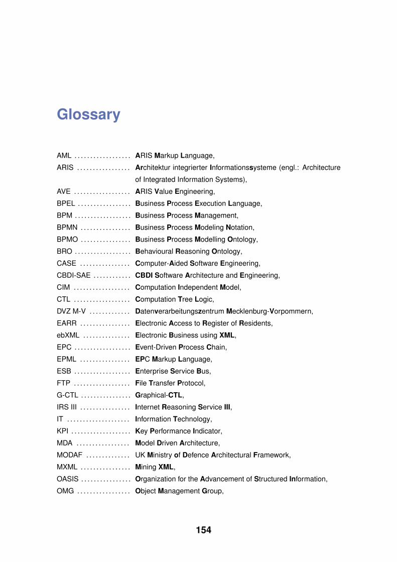
Glossary
AML . . . . . . . . . . . . . . . . . . ARIS Markup Language,
ARIS . . . . . . . . . . . . . . . . . Architektur integrierter Informationssysteme (engl.: Architecture
of Integrated Information Systems),
AVE . . . . . . . . . . . . . . . . . . ARIS Value Engineering,
BPEL . . . . . . . . . . . . . . . . . Business Process Execution Language,
BPM . . . . . . . . . . . . . . . . . . Business Process Management,
BPMN . . . . . . . . . . . . . . . . Business Process Modeling Notation,
BPMO . . . . . . . . . . . . . . . . Business Process Modelling Ontology,
BRO . . . . . . . . . . . . . . . . . . Behavioural Reasoning Ontology,
CASE . . . . . . . . . . . . . . . . Computer-Aided Software Engineering,
CBDI-SAE . . . . . . . . . . . . CBDI Software Architecture and Engineering,
CIM . . . . . . . . . . . . . . . . . . Computation Independent Model,
CTL . . . . . . . . . . . . . . . . . . Computation Tree Logic,
DVZ M-V . . . . . . . . . . . . . Datenverarbeitungszentrum Mecklenburg-Vorpommern,
EARR . . . . . . . . . . . . . . . . Electronic Access to Register of Residents,
ebXML . . . . . . . . . . . . . . . Electronic Business using XML,
EPC . . . . . . . . . . . . . . . . . . Event-Driven Process Chain,
EPML . . . . . . . . . . . . . . . . EPC Markup Language,
ESB . . . . . . . . . . . . . . . . . . Enterprise Service Bus,
FTP . . . . . . . . . . . . . . . . . . File Transfer Protocol,
G-CTL . . . . . . . . . . . . . . . . Graphical-CTL,
IRS III . . . . . . . . . . . . . . . . Internet Reasoning Service III,
IT . . . . . . . . . . . . . . . . . . . . Information Technology,
KPI . . . . . . . . . . . . . . . . . . . Key Performance Indicator,
MDA . . . . . . . . . . . . . . . . . Model Driven Architecture,
MODAF . . . . . . . . . . . . . . UK Ministry of Defence Architectural Framework,
MXML . . . . . . . . . . . . . . . . Mining XML,
OASIS . . . . . . . . . . . . . . . . Organization for the Advancement of Structured Information,
OMG . . . . . . . . . . . . . . . . . Object Management Group,
154

Glossary
OrViA . . . . . . . . . . . . . . . . Orchestrierung und Validierung integrierter Anwendungssysteme
(engl.: Orchestration and Validation of Integrated Application
Systems),
PIM . . . . . . . . . . . . . . . . . . Platform Independent Model,
PSM . . . . . . . . . . . . . . . . . . Platform Specific Model,
QoS . . . . . . . . . . . . . . . . . . Quality of Service,
REST . . . . . . . . . . . . . . . . Representational State Transfer,
sBPEL . . . . . . . . . . . . . . . semantic BPEL,
sBPMN . . . . . . . . . . . . . . . semantic BPMN,
sEPC . . . . . . . . . . . . . . . . . semantic EPC,
SESE . . . . . . . . . . . . . . . . Single Entry Single Exit,
SISi . . . . . . . . . . . . . . . . . . Semantic Invocation Service,
SLA . . . . . . . . . . . . . . . . . . Service Level Agreement,
SMTP . . . . . . . . . . . . . . . . Simple Mail Transfer Protocol,
SMV . . . . . . . . . . . . . . . . . . Symbolic Model Verifier,
sMXML . . . . . . . . . . . . . . . semantic MXML,
SOA . . . . . . . . . . . . . . . . . . Service-Oriented Architecture,
SUPER . . . . . . . . . . . . . . . Semantics Utilised for Process Management Within and Between
Enterprises,
TOGAF . . . . . . . . . . . . . . . The Open Group Architecture Framework,
TP . . . . . . . . . . . . . . . . . . . . Telekomunikacja Polska,
UDDI . . . . . . . . . . . . . . . . . Universal Description, Discovery and Integration,
UML . . . . . . . . . . . . . . . . . . Unified Modeling Language,
UPO . . . . . . . . . . . . . . . . . . Upper Process Ontology,
W3C . . . . . . . . . . . . . . . . . World Wide Web Consortium,
WSDL . . . . . . . . . . . . . . . . Web Service Description Language,
WSFL . . . . . . . . . . . . . . . . Web Services Flow Language,
WSML . . . . . . . . . . . . . . . . Web Service Modeling Language,
WSMO . . . . . . . . . . . . . . . Web Service Modeling Ontology,
WSMX . . . . . . . . . . . . . . . Web Service Modelling Execution Environment,
XML . . . . . . . . . . . . . . . . . . Extensible Markup Language,
XPDL . . . . . . . . . . . . . . . . . XML Process Definition Language,
XSD . . . . . . . . . . . . . . . . . . XML Schema Definition,
XSLT . . . . . . . . . . . . . . . . . Extensible Stylesheet Language Transformation,
155