modified space vector switching for three level npc ... · it is observed from simulation results...
TRANSCRIPT

International Journal of Scientific & Engineering Research, Volume 4, Issue 5, May-2013 2013 ISSN 2229-5518
IJSER © 2013 http://www.ijser.org
Modified Space Vector Switching for Three Level NPC Converter Based Unity Power Factor Conditioner in
Grid Connected WECS Naik. R. L,1 and Jangamshetti. S. H2
Abstract— This paper presents a Modified Space Vector Switching for three level NPC converter. A simplified switching strategy is developed by exploiting the redundant states of switching vectors available in three level space vectors. The proposed switching strategy is tested using the DSP TMS320F2812. It is observed that, the complexity of proposed switching strategy reduces to that of two level and has better harmonic performance as compared to conventional space vector PWM. Further, the developed switching strategy is used in voltage oriented controller to control grid connected three level NPC converter for variable speed WECS. Symmetrical optimum approach in designing of regulators for DC voltage and current control loops are proposed for voltage oriented control. The performance of controller is verified for constant and step change in wind speeds through simulation in MATLAB/SIMULINK. It is observed from simulation results that, the controller simultaneously regulates DC link voltage, maintains power factor at unity and overcomes the problem of voltage imbalance that exists between the capacitors of three level NPC converter connected to grid.
KEY WORDS.
Index Terms— Three level NPC converter, DSPTMS320F2812, WECS, SVPWM
—————————— ——————————
1 INTRODUCTION
n recent years, variable speed wind-energy conversion systems connected to grid have been increasing significantly in their size and capacity. Today rating of single wind turbine have reached up
to 5 MW. To transfer the energy from such high rated wind turbine to grid, multilevel converters, specifically three level NPC converters are more suitable [1]. The advantages of three-level NPC Converter are reduced voltage ratings for the switches, reduced harmonic distortion and lower electromagnetic interference. To control three level NPC converter, various modulation techniques are reported [2-6]. Among them, Space Vector PWM (SVPWM) is one of the promising modulation technique as it increases the modulation range by 15% compared to sinusoidal PWM[7]. Although three-level SVPWM technique is derived from two level SVPWM, it is considerably more complex as compared to two level. This is due to large number of converter switches and the problem of voltage balancing that exists between the capacitor of NPC converter. Researchers have developed various simplified SVM approach for three level NPC converter to over come said problems [7-8]. In [8] switching signals are generated for NPC converter using half wave, quarter wave symmetry and three phase symmetry. To implement this method, fictitious vector has to be created during the computation of time intervals for all six sectors, which increases the complexity and overloads the processors. The switching sequences are arranged in symmetrical pattern to reduce the complexity and computational time of the processor [7]. However in this approach, each switch is turned ‘ON’ more than once in each time period at unequal duty cycles. This will increase stress on individual switch and switching losses from medium to higher switching frequencies.
Further, to transfer the controlled power from wind turbine to the grid, grid side converter has to be controlled using grid side controller. Popularly, grid side converter is controlled using Voltage Oriented Control (VOC), in which the dq reference frame is usually aligned with the grid voltage vector [9-10]. This method guarantees an excellent dynamics and static performance via an internal control loop. However, the final configuration and performance of the system largely depends on the design of PI regulators for DC voltage and current control loops.
In view of the above identified problems in SVPWM for three level NPC converter and grid side controller, this paper presents Modified Space Vector Switching PWM (MSVSPWM) and simplified approach in designing of PI controllers for VOC. The details are given in the following sections.
2 SYSTEM DESCRIPTION AND MODEL
Wind turbine connected to grid using back-back converter scheme is shown in Fig.1. Information about generator side controller with MPPT is discussed in literature [12]. Grid side controller architecture used for development of modified space vector switching for three level NPC converter and designing of PI controller for grid side controller is shown in Fig.2
I IJSER
International Journal of Scientific & Engineering Research, Volume 4, Issue 5, May-2013 2014 ISSN 2229-5518
IJSER © 2013 http://www.ijser.org
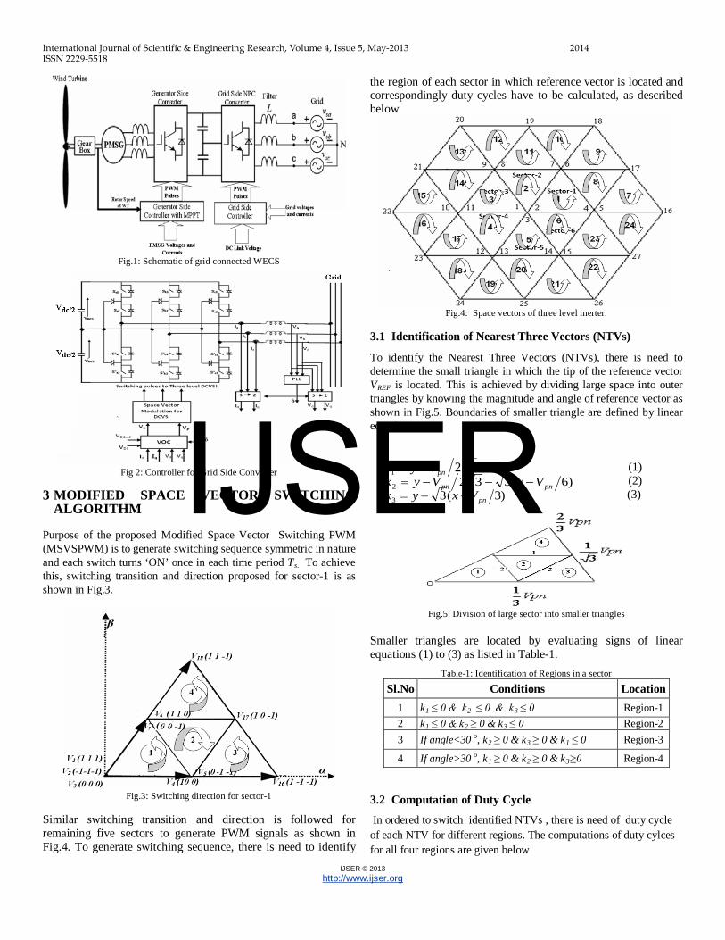
Fig.1: Schematic of grid connected WECS
Fig 2: Controller for Grid Side Converter
3 MODIFIED SPACE VECTOR SWITCHING
ALGORITHM
Purpose of the proposed Modified Space Vector Switching PWM (MSVSPWM) is to generate switching sequence symmetric in nature and each switch turns ‘ON’ once in each time period Ts. To achieve this, switching transition and direction proposed for sector-1 is as shown in Fig.3.
Fig.3: Switching direction for sector-1
Similar switching transition and direction is followed for remaining five sectors to generate PWM signals as shown in Fig.4. To generate switching sequence, there is need to identify
the region of each sector in which reference vector is located and correspondingly duty cycles have to be calculated, as described below
Fig.4: Space vectors of three level inerter.
3.1 Identification of Nearest Three Vectors (NTVs)
To identify the Nearest Three Vectors (NTVs), there is need to determine the small triangle in which the tip of the reference vector VREF is located. This is achieved by dividing large space into outer triangles by knowing the magnitude and angle of reference vector as shown in Fig.5. Boundaries of smaller triangle are defined by linear equations as
321 pnVyk −= (1) )6(3322 pnpn VxVyk −−−= (2)
)3(33 pnVxyk −−= (3)
Fig.5: Division of large sector into smaller triangles
Smaller triangles are located by evaluating signs of linear equations (1) to (3) as listed in Table-1.
Table-1: Identification of Regions in a sector
Sl.No Conditions Location 1 k1 ≤ 0 & k2 ≤ 0 & k3 ≤ 0 Region-1 2 k1 ≤ 0 & k2 ≥ 0 & k3 ≤ 0 Region-2 3 If angle<30 o, k2 ≥ 0 & k3 ≥ 0 & k1 ≤ 0 Region-3
4 If angle>30 o, k1 ≥ 0 & k2 ≥ 0 & k3≥0 Region-4
3.2 Computation of Duty Cycle
In ordered to switch identified NTVs , there is need of duty cycle of each NTV for different regions. The computations of duty cylces for all four regions are given below
IJSER

International Journal of Scientific & Engineering Research, Volume 4, Issue 5, May-2013 2015 ISSN 2229-5518
IJSER © 2013 http://www.ijser.org
1. Duty cycles of NTVs for VREF lies region-1 as shown in Fig.6a
)sin(2)sin()cos(31
))sin()cos(3(
1
θθθ
θθ
mdmmd
md
s
s
so
=−−=
−= (4)
Where, m is modulating index
2. Duty cycles of NTVs for VREF lies region-2 as shown in Fig.6b
)sin()cos(31
)sin()cos(31
)cos(21
1
θθ
θθ
θ
mmd
mmd
md
M
s
so
++−=
+−=
−= (5)
3. Duty cycles of NTVs for VREF lies in region-3 as shown in Fig.6c
( ) ( )
( )( ) ( )
3 cos sin 2
2 sin
1 3 cos sin
so
M
L
d m m
d m
d m m
θ θ
θ
θ θ
= − − +
=
= − + −
(6)
4. Duty cycles of NTVs for VREF lies in region-4 as shown in Fig.6d
1sin2sincos3
cos3sin2
−=−=
−−=
θθθ
θθ
mdmmd
mmd
L
M
SO (7)
Fig. 6: (a) Vref in region-1, (b) Vref in region-2, (c): Vref in region-3 and (d) Vref in region-4
3.3 Switching strategy
In this section switching sequences for different regions are presented to generate PWM switching signals. In the proposed switching strategy, each switch is turned ‘ON’ once in each time period Ts. The switching squence of all four regions for the first sector is shown in Table-2. Similar switching strategy is applied to other 6- sectors and 24 regions referring to the Fig.4.
Table-2: Switching Sequence for the first sector
Sector-1 Switching Sequence Region-1 2,5,7,3,4,6,1 1,6,4,3,7,5,2 return Region-2 5, 7, 17, 4 4, 17,7,5 return Region-3 5,16.17,4 4,17,16,5 return Region-4 7,17,18,6 6,18,17,7 return
4.0 TMS320F2812 DSP IMPLEMENTATION
In the present work TMS320F2812 DSP is used to implement MSVSPWM. This DSP has a dedicated Event Manager (EM) module for generation of PWM pulses. Traditionally EM module is designed for two level converters. However with a modified switching strategy, this module is programmed to generate PWM pulses for three level NPC converter. The DSP has six compare units, that is CMPR1, CMPR2, CMPR3, CMPR4, CMPR5 and CMPR6 for the generation of PWM pulses to switches Sa1, Sa2, Sb1, Sb2 , Sc1 and Sc2 referring to Fig,2.
The comparators and the timers have different modes of operation, which can be programmed using control registers GPTCON, COMCON and ACTR [13]. The GPTCON is programmed in continuous UP/DOWN count mode to implement symmetric SVPWM. The COMCON register is programmed to get following functions.
• The six comparators are enabled for PWM mode. • Timer 1 is used as time base for all the comparators, hence the
synchronization ensured. • The comparator registers, ACTR register and period register of
timer 1 (T1PR) are reloaded on period match.
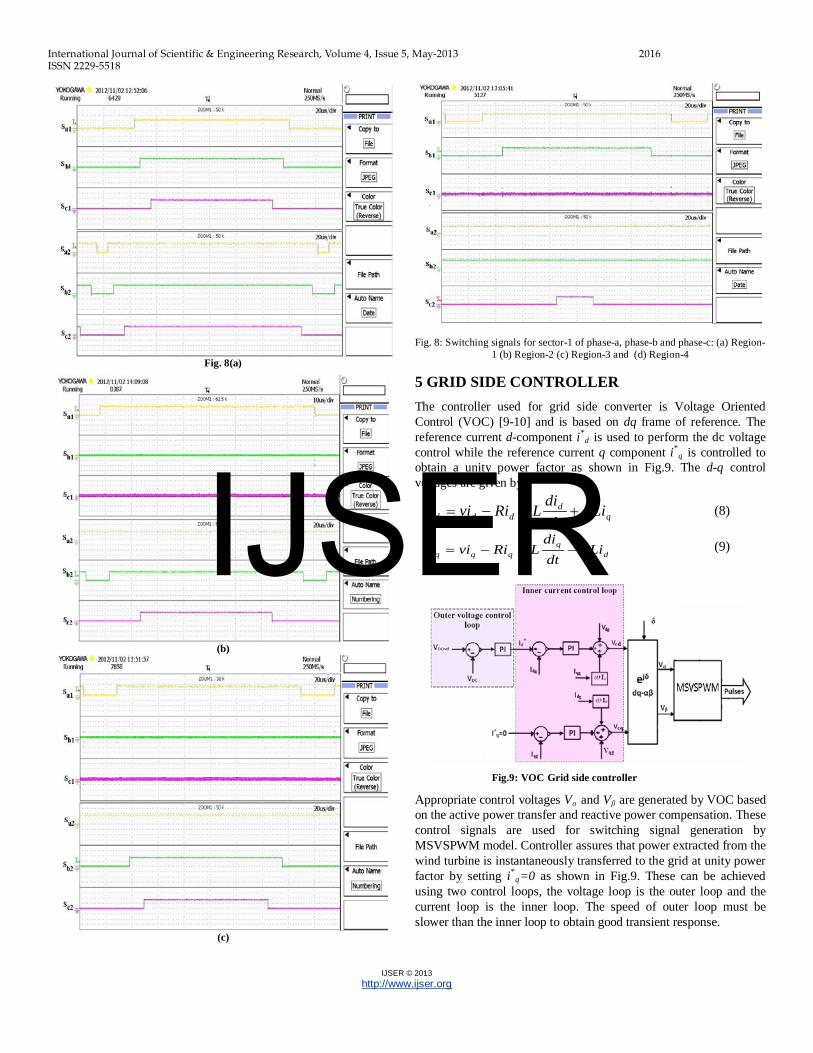
The ACTR register is used to program each comparator output either in Forced low or Forced high or Active high or Active low. Triangular wave is generated using GP timer1 and is compared with duty cycles of sector-1, region 2 for the generation of PWM pulses as shown in Fig.7. Above realization procedures is followed for remaining sectors. The switching pulses are obtained from DSP F2812 for the sector 1, Region-1 are shown in Fig.8. It is observed that, during implementation of three level SVPWM complexity is reduced to that of two level.
Fig.7: Generation of PWM pulses for phase-a, b and c
(b)
(c)
(a)
(d)
IJSER
International Journal of Scientific & Engineering Research, Volume 4, Issue 5, May-2013 2016 ISSN 2229-5518
IJSER © 2013 http://www.ijser.org
Fig. 8(a)
(b)
(c)
Fig. 8: Switching signals for sector-1 of phase-a, phase-b and phase-c: (a) Region-1 (b) Region-2 (c) Region-3 and (d) Region-4
5 GRID SIDE CONTROLLER The controller used for grid side converter is Voltage Oriented Control (VOC) [9-10] and is based on dq frame of reference. The reference current d-component i*
d is used to perform the dc voltage control while the reference current q component i*
q is controlled to obtain a unity power factor as shown in Fig.9. The d-q control voltages are given by.
qd
ddd Lidtdi
LRiviv ω+−−= (8)
d
qqqq Li
dtdi
LRiviv ω−−−= (9)
Fig.9: VOC Grid side controller
Appropriate control voltages Vα and Vβ are generated by VOC based on the active power transfer and reactive power compensation. These control signals are used for switching signal generation by MSVSPWM model. Controller assures that power extracted from the wind turbine is instantaneously transferred to the grid at unity power factor by setting i*
q=0 as shown in Fig.9. These can be achieved using two control loops, the voltage loop is the outer loop and the current loop is the inner loop. The speed of outer loop must be slower than the inner loop to obtain good transient response.
IJSER
International Journal of Scientific & Engineering Research, Volume 4, Issue 5, May-2013 2017 ISSN 2229-5518
IJSER © 2013 http://www.ijser.org
5.1 Voltage Control Loop
The block diagram of voltage control loop in s domain is shown in Fig.10. The DC-link voltage is controlled by means of the grid side controller, DC link capacitor taken as plant is given by [10].
sC
SGdc
dDC 4
3= (10)
Where, Sd is the switching steady state signal on d-axis and is averaged its value as 1 and CDC is the DC link capacitor.
Fig.10: Voltage Control Loop
sC
SsTsT
sTKG
dc
d
si
ipOL 4
33111
++
= (11)
The parameter Kp and Ti in (11) is chosen in accordance with the “symmetrical optimum” [14]. The cross-over frequency is chosen at the geometric mean of the two corner frequencies to obtain maximum phase margin, which results optimum damping of the voltage control loop. According to symmetrical optimum controller time Ti is taken as
si TaT 23= , a > 1 (12)
ψψ
sincos1+
=a (13)
Where, a is the responsible for cross over frequency and Ψ is the phase margin. The crossover frequency is
sis
c aTTT 31
31
==ω (14)
The cross over condition is applied for (11)
1)( =cOL jG ω (15)
The controller gain of voltage control loop is obtained from (15) and given by
sd
dcp TaS
CK
94
= (16)
To have the two complex conjugate poles of the closed loop transfer function critically damped (a = 2.4)
sd
dcp TS
CK 19.0= (17)
si TT 17= (18)
ss
bi TaTf
501
61
≈=π
(19)
The designed values of controller parameter for the proposed system Kp =1.9, Ti=8.85 ms and band width fbi = 45 Hz. The designed values are obtained for DC link capacitor CDC =500 μF and switching frequency fs=2 KHz
5.2 Current Control Loop for d and q axis Both current loops have the same dynamics. The tuning will be made only for one current controller, assuming for the other current loop having the same parameters. The block diagram of the synchronous current controller working in d-q coordinates is shown in Fig.11.
Fig.11: Current Control Loop
The transfer function of the open loop is given by
ssTsT
sTKG
si
ipOL τ++
+=
11
5.1111
(20)
Where, τ is the time constant of L filter and is given by L/R
To achieve the “technical optimum” (i.e. 5% overshoot) [14], the PI integrator time constant Ti should be chosen equal to the plant time constant T and the constant Kp is given as.
s
p TLK
3= (21)
ss
bi TTf
201
61
≈=π
(22)
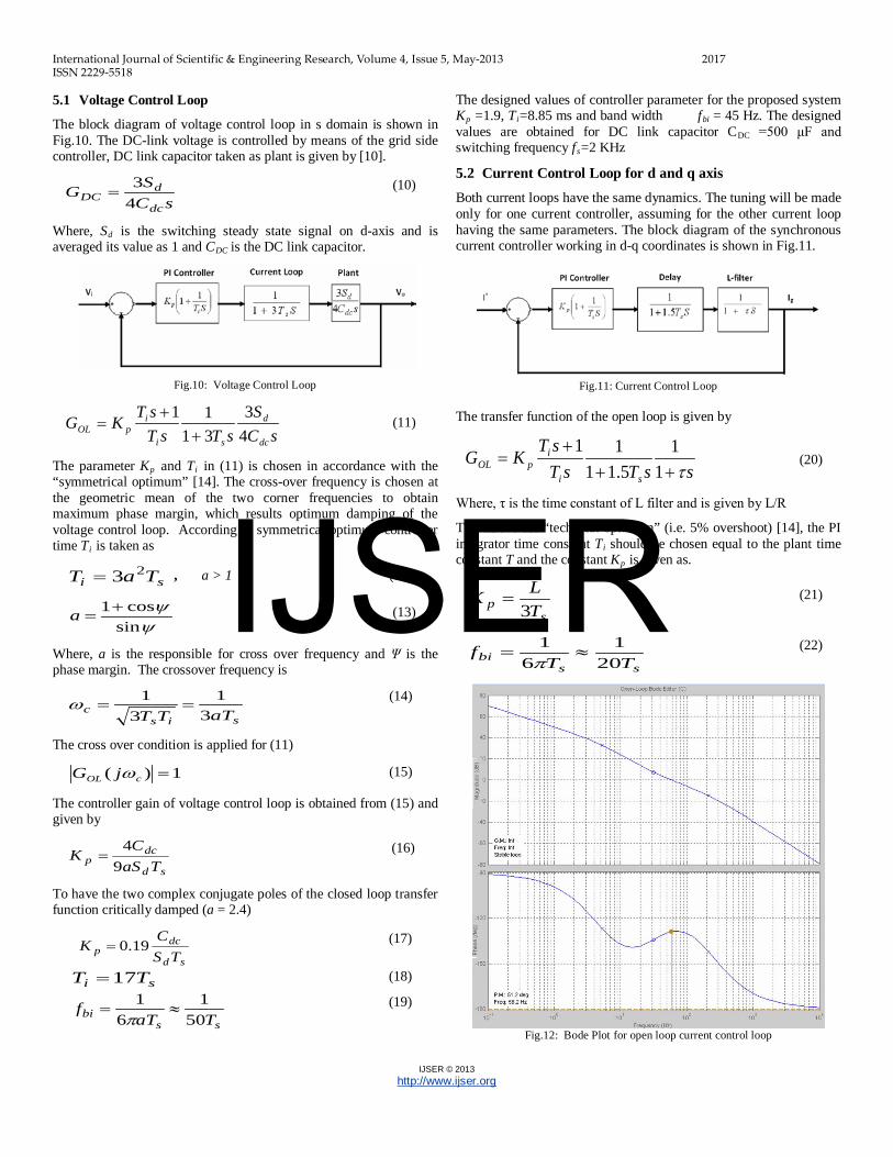
Fig.12: Bode Plot for open loop current control loop
IJSER

International Journal of Scientific & Engineering Research, Volume 4, Issue 5, May-2013 2018 ISSN 2229-5518
IJSER © 2013 http://www.ijser.org
Fig.13: Bode Plot for closed loop current control loop
The filter parameters considered for the proposed system are L=15 mH and R=0.5 Ω, the designed values of controller parameter Kp=10 and Ti =5ms. The open loop and closed loop bode plots of current controller are plotted as shown in Fig.12 and Fig.13 respectively. It is noted from Fig. 12 that, the controller is stable and the phase margin is 51.2o
. Further it is also observed from Fig 13 that, band width of current controller is obtained as 93 Hz. The speed of current controller is faster as compared voltage control loop i.e bandwidth is 40 Hz.
6.0 RESULTS AND DISCUSSION 6.1 Modified Space Vector Switching PWM
The performance of MSVSPWM is verified by simulating three level NPC converter connected to the R.L load. Simulation is carried out in MATLAB/ Simulink and tested for 2.5KVA and 0.9 power factor R-L load without controller. The line to line voltage of three level NPC converter is given in Fig.14 for Vdc=700 volts, m =0.85 and fs=2.0 KHz.
Fig.14: Line to Line Voltage
6.2 Performance Evaluation
The performance of proposed MSVSPWM algorithm for three level NPC converter is characterized by the Total Harmonic Distortion (THD), Weighted Total harmonic Distortion (WTHD) and DC mid point voltage.
Advantage of proposed MSVSPWM over conventional SVPWM in terms of THD variation is shown in Fig.15. It is noted that for the linear modulation index, m<0.577 the MSVSPWM has the lower THD as compared to the Conventional Space Vector Space Vector PWM (CSVPWM). Further WTHD gives a better measure of harmonic pollution by using the order of each harmonic component [11]. It is noted from Fig.16 that, for linear modulation index MSVSPWM has the much lower WTHD than CSVPWM. Even after linear modulation index it is found that MSSVPWM has no much variation in THD and WTHD compared to CSVPWM.
DC Bus mid point voltage
In three level NPC inverters the dc bus capacitors carry the load current. The unequal loading of the upper and lower capacitors causes the mid point voltage to fluctuate. The dc bus mid point voltage variation (ΔVo) is estimated from dc mid point current (io) is given as:
dtiC
VsT
oDC
o ∫=∆0
1 (23)
In proposed MSVSPWM small vectors are switched at the beginning and end of each state with equal ‘ON’ time to reduce voltage imbalance between the capacitors. The simulation results of DC bus capacitors and mid point voltage variation are shown in Fig.17. It is noted that NPC inverter maintains the Vdc/2 around both the capacitors and fluctuation of mid point voltage is minimum
Fig.15: Variation of THD versus Modulating Index ma
IJSER
International Journal of Scientific & Engineering Research, Volume 4, Issue 5, May-2013 2019 ISSN 2229-5518
IJSER © 2013 http://www.ijser.org
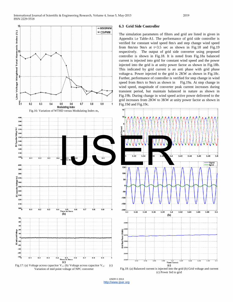
Fig.16: Variation of WTHD versus Modulating Index ma
(a)
(b)
(c)
Fig.17: (a) Voltage across capacitor Vc1. (b) Voltage across capacitor Vc2 (c) Variation of mid point voltage of NPC converter
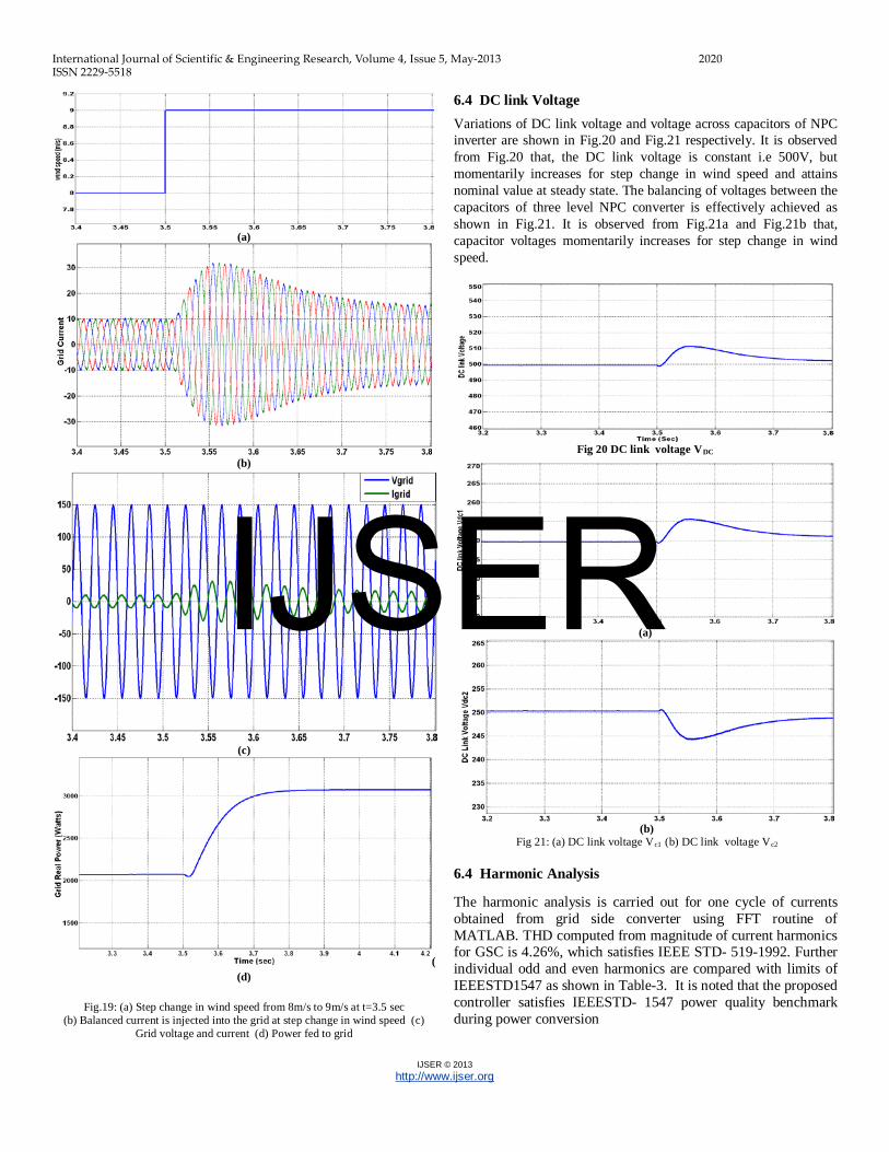
6.3 Grid Side Controller The simulation parameters of filters and grid are listed in given in Appendix i.e Table-A1. The performance of grid side controller is verified for constant wind speed 8m/s and step change wind speed from 8m/sto 9m/s at t=3.5 sec as shown in Fig.18 and Fig.19 respectively. The output of grid side converter using proposed controller is shown in Fig.18. It is noted from Fig.18a balanced current is injected into grid for constant wind speed and the power injected into the grid is at unity power factor as shown in Fig.18b. This indicated by grid current is an anti phase with grid phase voltage-a. Power injected to the grid is 2KW as shown in Fig.18c. Further, performance of controller is verified for step change in wind speed from 8m/s to 9m/s as shown in Fig.19a. At step change in wind speed, magnitude of converter peak current increases during transient period, but maintain balanced in nature as shown in Fig.19b. During change in wind speed active power delivered to the grid increases from 2KW to 3KW at unity power factor as shown in Fig.19d and Fig.19c.
(a)
(b)
(c)
Fig.18: (a) Balanced current is injected into the grid (b) Grid voltage and current (c) Power fed to grid
IJSER
International Journal of Scientific & Engineering Research, Volume 4, Issue 5, May-2013 2020 ISSN 2229-5518
IJSER © 2013 http://www.ijser.org
(a)
(b)
(c)
((d)
Fig.19: (a) Step change in wind speed from 8m/s to 9m/s at t=3.5 sec (b) Balanced current is injected into the grid at step change in wind speed (c)
Grid voltage and current (d) Power fed to grid
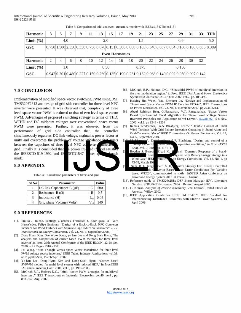
6.4 DC link Voltage
Variations of DC link voltage and voltage across capacitors of NPC inverter are shown in Fig.20 and Fig.21 respectively. It is observed from Fig.20 that, the DC link voltage is constant i.e 500V, but momentarily increases for step change in wind speed and attains nominal value at steady state. The balancing of voltages between the capacitors of three level NPC converter is effectively achieved as shown in Fig.21. It is observed from Fig.21a and Fig.21b that, capacitor voltages momentarily increases for step change in wind speed.
Fig 20 DC link voltage VDC
(a)
(b)
Fig 21: (a) DC link voltage Vc1 (b) DC link voltage Vc2
6.4 Harmonic Analysis The harmonic analysis is carried out for one cycle of currents obtained from grid side converter using FFT routine of MATLAB. THD computed from magnitude of current harmonics for GSC is 4.26%, which satisfies IEEE STD- 519-1992. Further individual odd and even harmonics are compared with limits of IEEESTD1547 as shown in Table-3. It is noted that the proposed controller satisfies IEEESTD- 1547 power quality benchmark during power conversion
IJSER
International Journal of Scientific & Engineering Research, Volume 4, Issue 5, May-2013 2021 ISSN 2229-5518
IJSER © 2013 http://www.ijser.org
Table-3: Comparison of odd and even current harmonic with IEEEstd1547 limits [15]
Harmonic
3 5 7 9 11 13 15 17 19 21 23 25 27 29 31 33 TDD Limit (%) 4.0 2.0 1.5 0.6 5.0
GSC
0.750 1.500 2.550 0.330 0.750 0.678 0.151 0.306 0.088 0.103 0.340 0.037 0.064 0.100 0.100 0.055 0.389
Even Harmonics
Harmonic
2 4 6 8 10 12 14 16 18 20 22 24 26 28 30 32
Limit (%) 1.0 0.50 0.375 0.150
GSC
0.942 0.201 0.480 0.227 0.150 0.269 0.135 0.190 0.231 0.132 0.068 0.140 0.092 0.050 0.097 0.142
7.0 CONCLUSION Implementation of modified space vector switching PWM using DSP TMS320F2812 and design of grid side controller for three level NPC inverter were presented. It was observed that, complexity of three level space vector PWM is reduced to that of two level space vector PWM. Advantages of proposed switching strategy in terms of THD, WTHD and DC midpoint voltages over conventional space vector PWM were presented. Further, it was observed from the performance of grid side controller that, the controller simultaneously regulates DC link voltage, maintains power factor at unity and overcomes the problem of voltage imbalance that exists between the capacitors of three level NPC converter connected to grid. Finally it is concluded that the power injected to grid satisfies the IEEESTD-519-1992 and IEEESTD1547 power quality bench mark.
8.0 APPENDIX
Table-A1: Simulation parameters of filters and grid
Sl.No Parameter Value 1 DC link Capacitance C (µF) : C 500 2 Resistance R (Ω) : R 0.5 3 Inductance (H) Lsi 0.05 4 Grid phase Voltage (Volts) Vph 140
9.0 REFERENCES [1]. Emilio J. Bueno, Santiago C´obreces, Francisco J. Rodr´ıguez, A´ lvaro
Herna´ndez, Felipe Espinosa, “Design of a Back-to-Back NPC Converter Interface for Wind Turbines with Squirrel-Cage Induction Generator”, IEEE Transactions on Energy Conversion, Vol. 23, No. 3, September 2008.
[2]. Dong Hyun Kim, Dae Wook Kang, yo han Lee and Dong Soek Hyun,“The analysis and comparison of carrier based PWM methods for three level inverter",in Proc. 26th Annual Conference of the IEEE-IECON, 22-28 Oct. 2000, vol.2 Pages:1316 - 1321.
[3]. Fei Wang, ”Sine Triangle versus space vector modulation for three-level PWM voltage source inverters," IEEE Trans. Industry Applications, vol.38, no.2, pp500-506, March/April 2002.
[4]. Yo-han Lee, Dong-Hyun Kim and Dong-Seok Hyun, “Carrier based SVPWM method for multi level system with reduced HDF," in Proc.IEEE IAS annual meeting Conf. 2000, vol.3, pp. 1996-2003.
[5]. McGrath B.P., Holmes D.G., “Multi carrier PWM strategies for multilevel inverters ,” IEEE Transactions on Industrial Electronics, vol.49, no.4 , pp. 858 -867, Aug. 2002.
[6]. McGrath, B.P.; Holmes, D.G., “Sinusoidal PWM of multilevel inverters in the over modulation region," in Proc. IEEE 33rd Annual Power Electronics Specialists Conference, 23-27 June 2002, vol.2, pp. 485-490.
[7]. Haibing Hu, Wenxi Yao, Zhengyu Lu, “Design and Implementation of Three-Level Space Vector PWM IP Core for FPGAs”, IEEE Transactions on Power Electronics, Vol. 22, No. 6, November 2007, pp 2234-2244.
[8]. Abdul Rahiman Beig, G.Narayanan, V.T. Ranganathan, “Space Vector Based Synchronized PWM Algorithm for Three Level Voltage Source Inverters: Principles and Application to V/f Drives”, IECON 02 , 5-8 Nov. 2002, vol.2, pp 1249 - 1254
[9]. Remus Teodorescu, Frede Blaabjerg, Fellow “Flexible Control of Small Wind Turbines With Grid Failure Detection Operating in Stand-Alone and Grid-Connected Mode” IEEE Transactions On Power Electronics, Vol. 19, No. 5, September 2004.
[10]. M. Liserre, A. Dell’Aquila, and F. Blaabjerg, “Design and control of a three-phase rectifier under non ideal operating conditions,” in Proc. IAS’02 Conf., vol. 2, 2002, pp. 1181–1188
[11]. Bogdan S. Borowy, Ziyad M. Salameh “Dynamic Response of a Stand-Alone Wind Energy Conversion System with Battery Energy Storage to a Wind Gust” IEEE Transactions on Energy Conversion, Vol. 12, No. 1, pp 73-78, March 1997.
[12]. Naik. R. L, Jangamshetti. S. H, “Control Strategy For Current Controlled Generator Side Converter Based Power Factor Conditioner For Variable Speed WECS”, communicated to sixth IASTED Asian conference on Power and Energy System 2013 at Phuket, Thailand
[13]. Reference guide of TMS320x281x DSP Event Manager (EV), Literature Number: SPRU065D November 2004 − Revised August 2006.
[14]. C. Krause. Analysis of electric machinery. 2nd Edition. United States of America: Willey, 2002
[15]. IEEE Application Guide for IEEE Std 1547™, IEEE Standard for Interconnecting Distributed Resources with Electric Power Systems, 15 April 2009.
IJSER