n0960f major line - ciat · 2019-01-22 · n 09.60 f fr-1 la société &,$7 vous remercie de...
TRANSCRIPT

10-2015
N 09.60F
MAJ
OR
LIN
E
Manuel d'instructionsInstruct ion manualB e n u t z e r h a n d b u c hManual de instruccionesManuale di istruzioniI n s t r u c t i e h a n d b o e k
Használati útmutató

35kg
+50°C
-10°C
1
2
1
467 7
8
9
10
11
12
5
35
1 2
3
4
2
3
4
100 mm mini
a
a
b
c

5
6
7
a
a b a
c
b
d
7
V4 V5 V6PE PE Ph Ph N
MVCd
N
Q
1
2
N N V1 V2 V3
+
230/1/50
g g a b c d e f
9
8
230/1/50
N
Q
1
2
MVCd
BSCM
BSCA
R1 R2
V4 V5 6 7PEXB PE Ph Ph Ph N N N N V1 V2 V3
g g a b c d e f
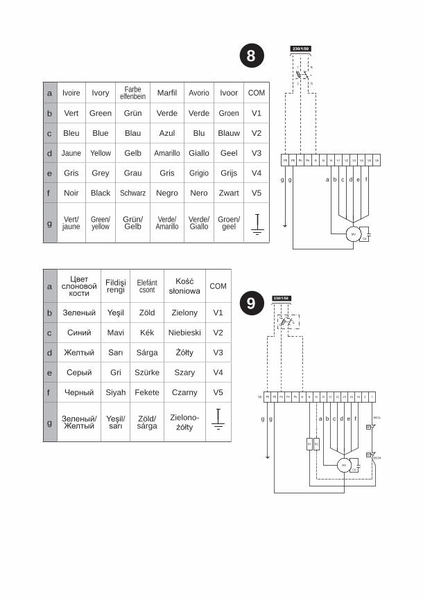
a Ivoire Ivory Farbe elfenbein Marfil Avorio Ivoor COM
b Vert Green Grün Verde Verde Groen V1
c Bleu Blue Blau Azul Blu Blauw V2
d Jaune Yellow Gelb Amarillo Giallo Geel V3
e Gris Grey Grau Gris Grigio Grijs V4
f Noir Black Schwarz Negro Nero Zwart V5
g Vert/jaune
Green/ yellow
Grün/ Gelb
Verde/Amarillo
Verde/ Giallo
Groen/ geel
a rengiElefánt csont COM
b Zöld Zielony V1
c Mavi Kék Niebieski V2
d Sárga V3
e Gri Szürke Szary V4
f Siyah Fekete Czarny V5
g Zöld/sárga
Zielono-
11
12
a b
c
a
a
c
d
b
10
13
14
15
abc
d
b
a
a
16
b
b
a
17
a
b
c
d

18
e

c
f
a
b
n
i
j
k
l
m
d
e
w
g/h
19
102A/102C/104X
202A/202C/202D/204X
302A/302B/302C/304X
402C/404X 502C/504X 602C/604X
a 7203338 7203339 7203340 7203341 7203342 7203343
b 7241968 7241969 7241970 7241971 7241972 7241973c 7203420 7203421 7203422 7203423 7203424 7203425d 7203408
e 7203344
f 7203345
7203409
h 7203410
i 7167660 (x1) 7167661(x1) 7167660 (x2) 7167661 (x2) 7244505 (x2) 7244505 (x2)j 7243915 7243916 7243917 7243918 7243918 7243919k 7203352 (x1) 7203353 (x1) 7203352 (x2) 7203353 (x2) 7203354 (x2) 7203354 (x2)l 7203355 (x1) 7203356 (x1) 7203355 (x2) 7203356 (x2) 7203357 (x2) 7203357 (x2)m 7203358 7203359 7203360 7203361 7203362 7203363n 7203346 7203347 7203348 7203349 7203350 7203351
t
uv
q
s
r
o
p
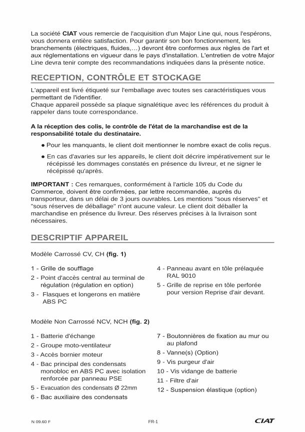
102A/102C/104X
202A/202C/202D/204X
302A/302B/302C/304X
402C/404X 502C/504X 602C/604X
o+v 7418371 7418372 7418373 7418374 7418375 7418376
p 7203498
q 7203365
r 7203364
s 7203378 7203379 7203380 7203381 7203382 7203383
t 7203384 7203385 7203386 7203387 7203388 7203389
u 7203390 7203391 7203392 7203393 7203394 7203395
w
102A 7203450
202A 7203452
302C 7203454
402A 7203456
502A 7203458
w
102C 7203451
202C 7203453
302C 7203455
402C 7203457
502C 7203459
602C 7203460
w
104X 7203462
204X 7203463
304X 7203464
404X 7203465
504X 7203466
604X 7203467
102B 7239151
202B 7239153
302B 7239157
402B 7239159
602B 7239161
102D 7239151
202D 7239153
302D 7239157
402D 7239159
502D 7239161
602D 7239162
104Y 7239145
204Y 7239146
304Y 7239147
404Y 7239148
504Y 7239149
604Y 7239150
N 09.60 F FR-1
La société vous remercie de l'acquisition d'un Major Line qui, nous l'espérons, vous donnera entière satisfaction. Pour garantir son bon fonctionnement, les
Line devra tenir compte des recommandations indiquées dans la présente notice.
L'appareil est livré étiqueté sur l'emballage avec toutes ses caractéristiques vous
Chaque appareil possède sa plaque signalétique avec les références du produit à rappeler dans toute correspondance.
responsabilité totale du destinataire.
En cas d'avaries sur les appareils, le client doit décrire impérativement sur le récépissé les dommages constatés en présence du livreur, et ne signer le récépissé qu'après.
Ces remarques, conformément à l'article 105 du Code du
transporteur, dans un délai de 3 jours ouvrables. Les mentions "sous réserves" et "sous réserves de déballage" n'ont aucune valeur. Le client doit déballer la marchandise en présence du livreur. Des réserves précises à la livraison sont nécessaires.
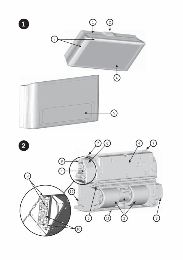
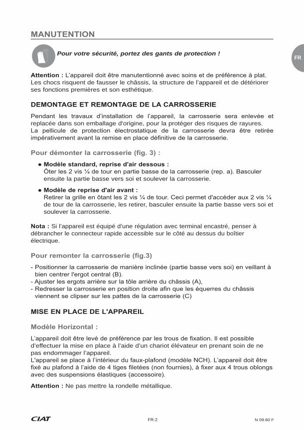
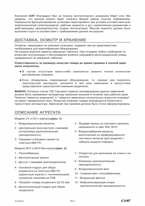
2 - Point d'accès central au terminal de
3 - Flasques et longerons en matière ABS PC
4 - Panneau avant en tôle prélaquée RAL 9010
5 - Grille de reprise en tôle perforée pour version Reprise d'air devant.
1 - Batterie d'échange2 - Groupe moto-ventilateur3 - Accès bornier moteur4 - Bac principal des condensats
monobloc en ABS PC avec isolation renforcée par panneau PSE
5 - Evacuation des condensats Ø 22mm
au plafond
9 - Vis purgeur d'air10 - Vis vidange de batterie11 - Filtre d'air
Modèle Non Carrossé NCV, NCH
Modèle Carrossé CV, CH
FR
FR-2 N 09.60 F
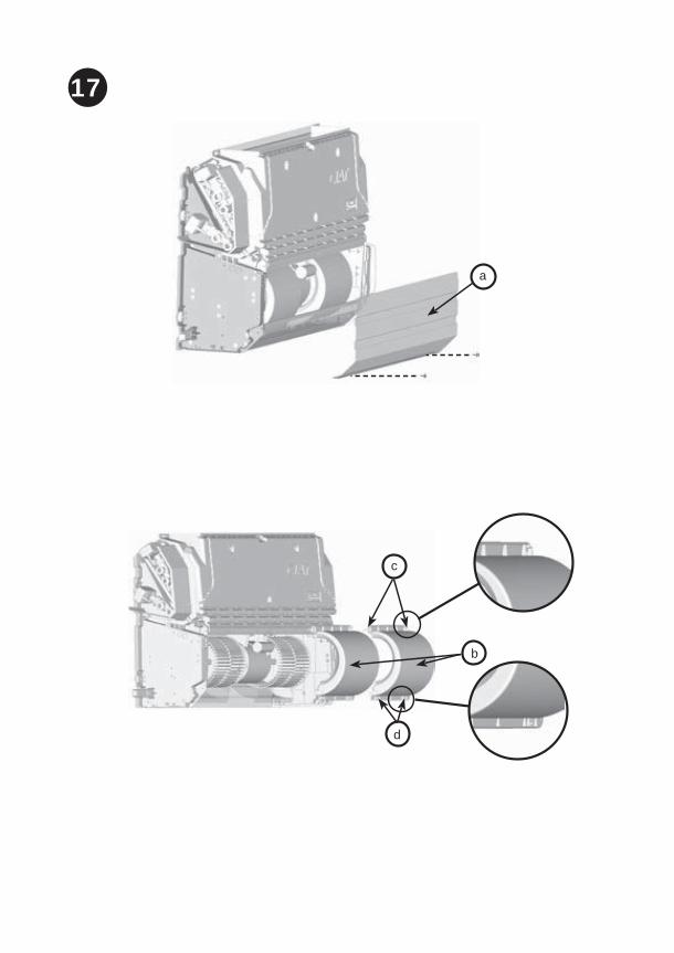
Pour votre sécurité, portez des gants de protection !
Les chocs risquent de fausser le châssis, la structure de l’appareil et de détériorer ses fonctions premières et son esthétique.
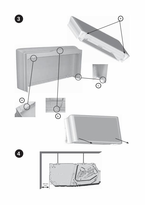
replacée dans son emballage d'origine, pour la protéger des risques de rayures.
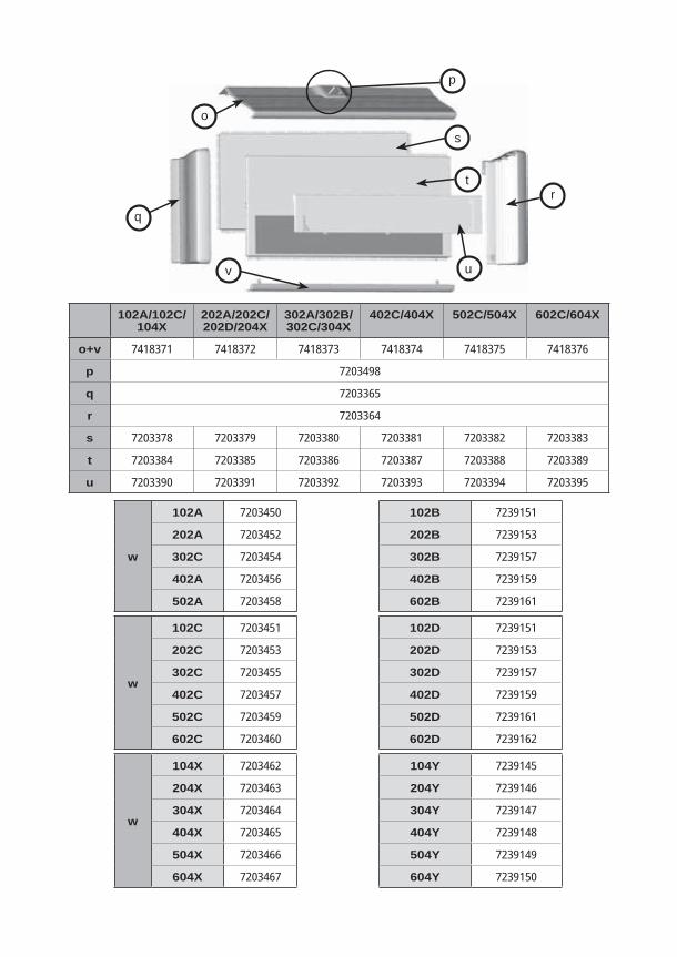
ensuite la partie basse vers soi et soulever la carrosserie.
de tour de la carrosserie, les retirer, basculer ensuite la partie basse vers soi et soulever la carrosserie.
Si l’appareil est équipé d’une régulation avec terminal encastré, penser à débrancher le connecteur rapide accessible sur le côté au dessus du boîtier électrique.
d’effectuer la mise en place à l’aide d’un chariot élévateur en prenant soin de ne pas endommager l’appareil.
Ne pas mettre la rondelle métallique.
N 09.60 F FR-3
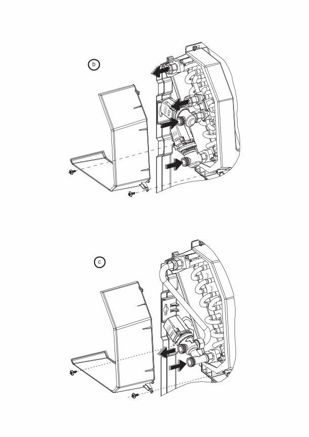
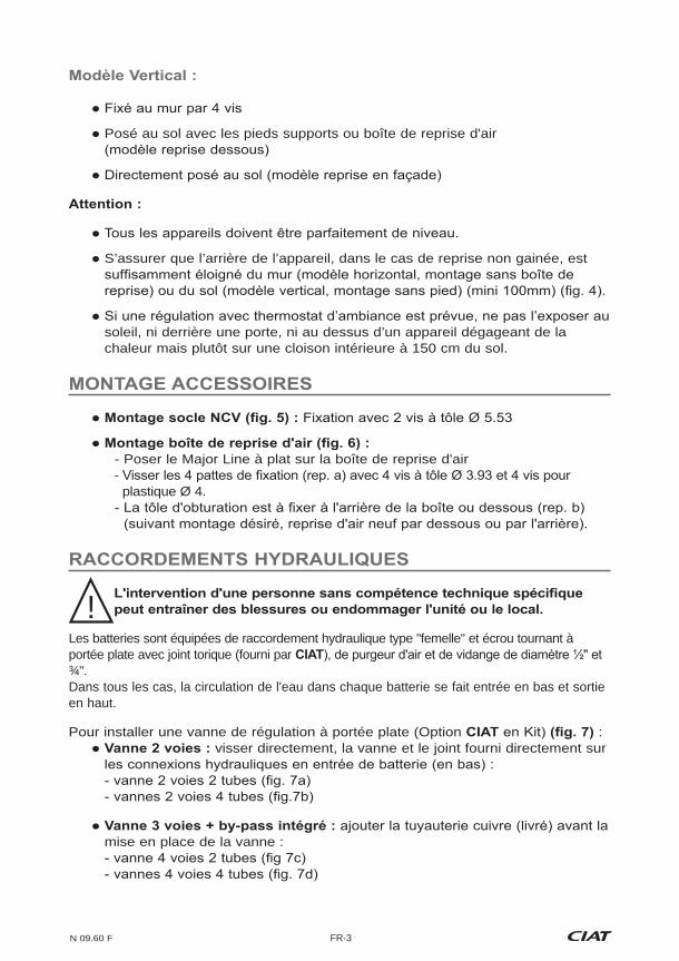
Posé au sol avec les pieds supports ou boîte de reprise d'air
S’assurer que l’arrière de l’appareil, dans le cas de reprise non gainée, est
soleil, ni derrière une porte, ni au dessus d’un appareil dégageant de la chaleur mais plutôt sur une cloison intérieure à 150 cm du sol.
- Poser le Major Line à plat sur la boîte de reprise d'air -
plastique Ø 4.
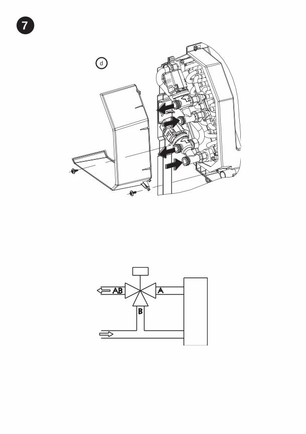
Les batteries sont équipées de raccordement hydraulique type "femelle" et écrou tournant à portée plate avec joint torique (fourni par ¾".Dans tous les cas, la circulation de l'eau dans chaque batterie se fait entrée en bas et sortie en haut.
Pour installer une vanne de régulation à portée plate (Option : visser directement, la vanne et le joint fourni directement sur
mise en place de la vanne :
!

FR
FR-4 N 09.60 F
Installation
Pour ne pas détériorer ce raccord ou la vanne , ne pas appliquer un couple de serrage supérieur à 3,5 daN.m. Utiliser 2 clés, une de maintien, l’autre de serrage pour garantir l’étanchéité du raccord de vanne.
Bien respecter le sens de montage de la vanne. Sur ces vannes la circulation doit se faire de A > AB
est de 100 kPa. préconise de ne pas dépasser 60 kPa.
Recommandations hydrauliques
fonctionnement de l'installation. Pour cela prévoyez des vannes de vidange bien placées et en nombre suffisant, des pots à boue, des purges correctement installées en position haute du circuit, des tés d'équilibrage sur chaque Major Line et des vannes de décharge si nécessaire.
A AB
Vannes thermiques : Enlever le servo-moteur pour mettre en place le bouchon, ce qui provoquera l'appui sur l'arbre donc l'ouverte du passage ou faire une demande d'ouverture de la vanne par la commande.
Vannes modulantes 3 Points : Si la mise en tension n'a pas été encore effectuée, par défaut la vanne sera ouverte. Dans le cas contraire, si la régulation a déjà été mise sous tension, enlever le servo-moteur, ce qui permettra de libérer la tige et donc l'ouverture du passage.
AB A
B
Purgez les batteries lors de la mise en service.
N 09.60 F FR-5
Pour les vannes équipées de moteurs thermiques, veiller à ce que l'ambiance environnante du moteur de vanne ne dépasse pas 50°C pour éviter tout risque d'ouverture intempestive. Risque à prendre en compte notamment pour les appareils
erreur de conception du réseau d'alimentation hydraulique ou d'une erreur de mise en service.
nécessaire de calorifuger les tuyauteries sur toute leur longueur en s'assurant que
l'alimentation des appareils. En cas de surchauffe de la batterie électrique, une élévation ponctuelle de la température de l'eau est possible. Celle-ci peut faire chuter très rapidement
S'assurer, avant toute intervention, que l'appareil soit hors tension en coupant l'alimentation électrique.
Les personnes intervenant sur les raccordements électriques doivent
entretiens.
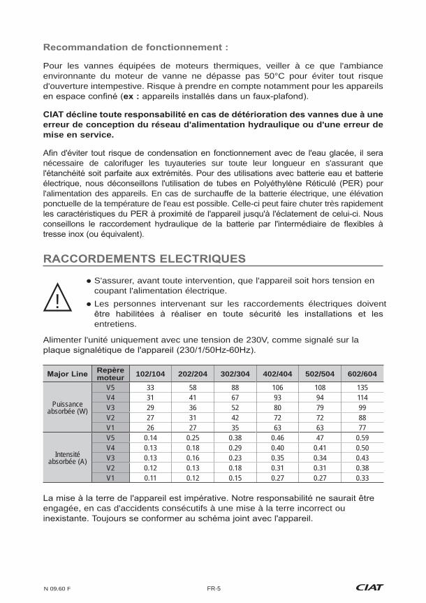
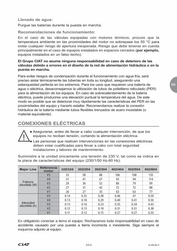
Alimenter l'unité uniquement avec une tension de 230V, comme signalé sur la
!
Repère moteur 102/104 202/204 302/304 402/404 502/504 602/604
Puissance absorbée (W)
V5 33 58 88 106 108 135V4 31 41 67 93 94 114V3 29 36 52 80 79 99V2 27 31 42 72 72 88V1 26 27 35 63 63 77
Intensité absorbée (A)
V5 0.14 0.25 0.38 0.46 47 0.59V4 0.13 0.18 0.29 0.40 0.41 0.50V3 0.13 0.16 0.23 0.35 0.34 0.43V2 0.12 0.13 0.18 0.31 0.31 0.38V1 0.11 0.12 0.15 0.27 0.27 0.33
engagée, en cas d'accidents consécutifs à une mise à la terre incorrect ou

FR
FR-6 N 09.60 F
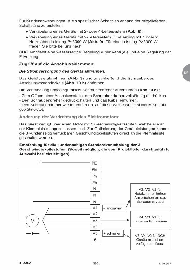
Pour des applications client, le schéma électrique est à concevoir à partir des schémas fournis :
résistances
CIAT préconise l'utilisation d'une régulation de l'appareil sur l'eau (active sur la ou
Mettre l'appareil hors tension en coupant l'alimentation électrique.
Démonter la carrosserie puis retirer la vis du capot du boîtier électrique .
Utiliser impérativement un tournevis pour procéder au câblage :
- Insérer le câble tout en maintenant le tournevis- Enlever ensuite le tournevis, le contact est alors établi de manière sûre.
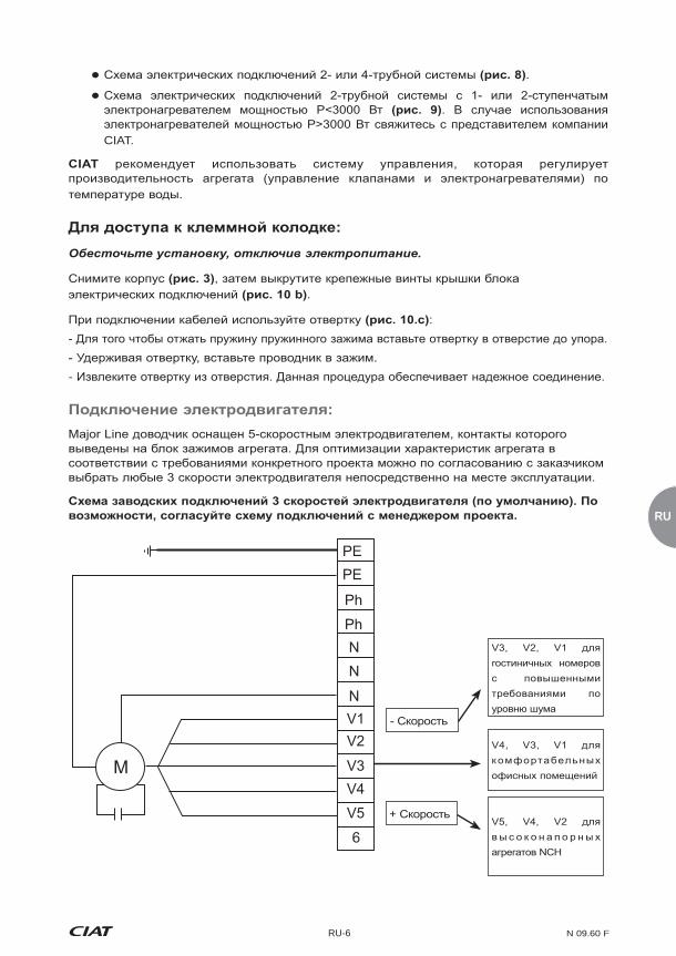
Major Line dispose d’un moteur à 5 vitesses, toutes ramenées sur le bornier de l'appareil. Pour optimiser les performances de l'appareil, il est possible d'adapter les 3 vitesses client sur site directement sur le bornier.
V3, V2, V1 pour chambres d’hôtels à forte contrainte acoustique
V4, V3, V1 pour
standing
V5, V4, V2 pour des appareils NCH avec une forte pression disponible
PEPE
Ph
NN
NV1V2
V3MV4V5
6
Ph
- Vite
N 09.60 F FR-7
intempestif du groupe moto-ventilateur doit entraîner impérativement la coupure de l'alimentation des résistances électriques et une post-ventilation.
bon fonctionnement de nos sécurités.
La protection contre la surchauffe accidentelle des appareils équipés de
placé toujours côté boitier électrique. Le réarmement éventuel des thermostats ne sera effectué qu'après avoir recherché les causes de la surchauffe ayant provoqué un déclenchement de celui-ci :
> Mise sous tension sans ventilation.
Ne jamais raccorder plusieurs moteurs de ventilo-convecteur en
à la norme internationale de référence CEI 60364 (Installations électriques des
Un bac polymère incliné sans rétention d'eau équipe le MAJOR LINE, équipé d'un
il est donc impératif d’ôter le bouchon selon le coté du raccordement hydraulique choisi.
mettre le
Le raccordement peut s'effectuer par la gauche ou par la droite de l'appareil.
raccordée à une tuyauterie principale d’évacuation. Utiliser un tube d’évacuation transparent et/ou rigide pour une pente de 1 cm/m minimum, avec un dénivelé
!

FR
FR-8 N 09.60 F
constant tout le long du parcours. Prévoir un siphon d’au moins 5 cm pour éviter tout refoulement de gaz ou d’odeurs désagréables.
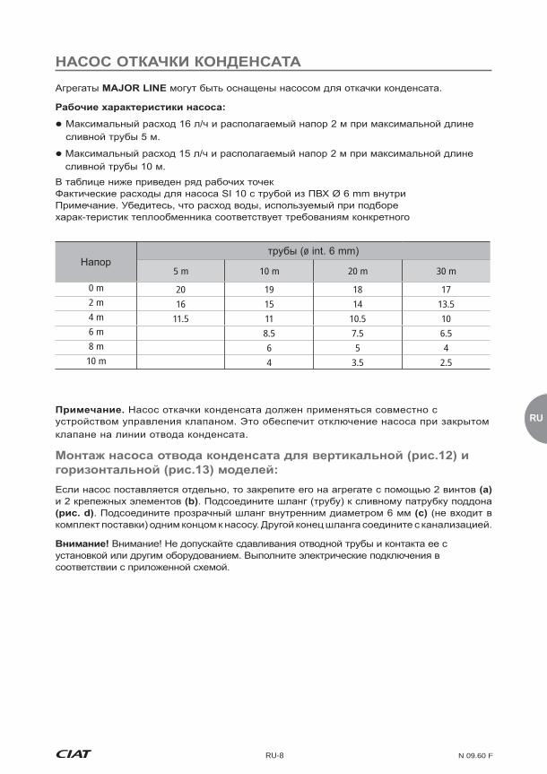
Une pompe de relevage peut équiper les .
Se référer au tableau ci-dessous pour les différents points de fonctionnement.Tableau des débits réels pour la pompe SI 10 avec tube PVC Ø 6 mm intérieur.
Hauteur de refoulementLongueur de tuyauterie (ø int. 6 mm)
5 m 10 m 20 m 30 m
0 m 20 19 18 172 m 16 15 14 13.54 m 11.5 11 10.5 106 m 8.5 7.5 6.58 m 6 5 410 m 4 3.5 2.5
Bien vérifier que le débit d'eau à évacuer dans la sélection thermique correspond bien à votre cas d'application
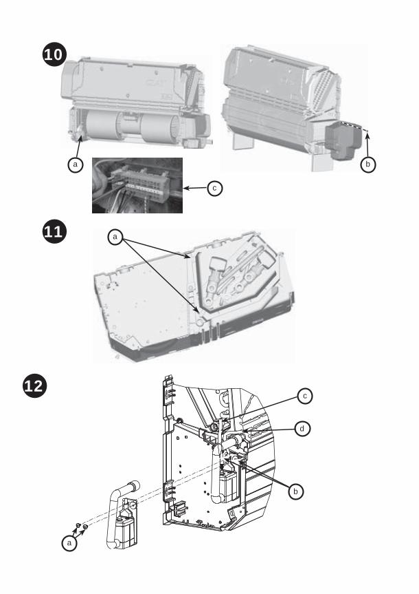
Dans le cas où celle-ci est livrée séparément sous forme de kit, visser sur l'appareil l'ensemble à l'aide des 2 plots et 2 vis , connecter la durite de raccordement au bac de condensats . Connecter un tuyau d'évacuation transparent non fourni de diamètre 6 mm intérieur entre le refoulement de la pompe et le conduit d'eau usée.
N 09.60 F FR-9
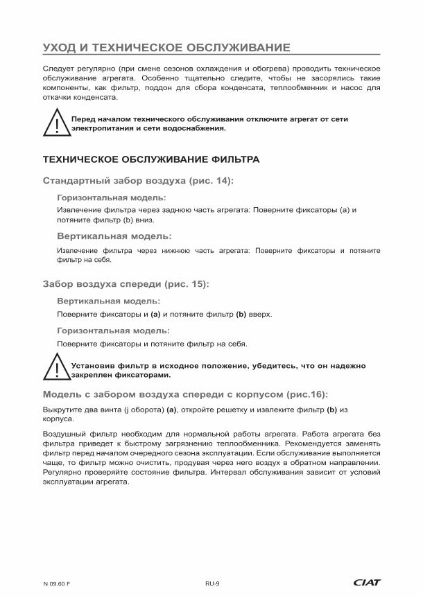
Un entretien périodique entre les saisons de chauffe et de rafraîchissement est à prévoir, notamment pour les éléments subissant un encrassement : filtre, bac des
coupant l'alimentation électrique et hydraulique.
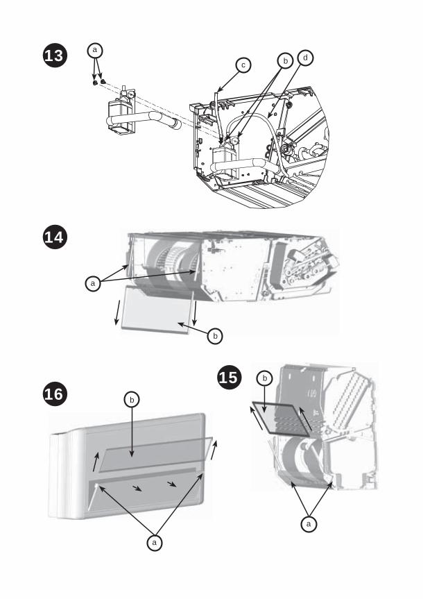
Retrait du filtre par la partie arrière de l'appareil : Pivoter les glissières
Retrait du filtre par la partie inférieure de l'appareil : Pivoter les glissières et faire glisser le filtre vers soi en le libérant des glissières.
en le tirant vers le haut.
Pour retirer le filtre, faire pivoter les glissières et libérer le filtre en le tirant vers soi.
verrouiller.
Tourner les 2 vis ¼ de tour de son logement.
colmatage de la batterie d’échange. Nous préconisons son échange entre chaque
!
!

FR
FR-10 N 09.60 F
hors tension.
Retirer le groupe moteur/turbine de l'appareil.
Faire l’opération inverse pour le remontage.
nécessaire, les nettoyer à l’aide d’un aspirateur en prenant soin de ne pas les endommager. Le moteur électrique ne nécessite aucun entretien particulier.
Le bac des condensats doit rester propre. Un nettoyage complet du bac plastique et de ses douilles peut se faire à l'aide de produits détergents à l'eau non abrasifs.
Ce nettoyage peut s'effectuer en retirant le bac en dévissant les 2 vis latérales et les 2 vis frontales du bac .
L'état de propreté de la batterie est un facteur déterminant pour le bon rendement de l'appareil en cas de nécessité, nettoyer la batterie à l'aide d'un aspirateur.S'il est nécessaire de démonter la batterie en cas de fuite :
Déconnecter la batterie eau et l'évacuation des condensats.
Dévisser les vis latérales de la batterie d'échange et en la dégageant de son emplacement entre les pieds support de l'appareil.
Il est possible d'effectuer le démontage du bac des condensats sans retrait de la batterie d'échange.

N 09.60 F FR-11
Pour garantir l’esthétique de l’appareil, passer une éponge humide légèrement
détergents à l'eau non abrasifs.
a - Panneau arrièreb - Filtrec - Batterie électrique 1 ou 2 résistance
e - Pied droit support châssisf - Pied gauche support châssis
i - Turbine
k - Demi-volute supérieurel - Demi-volute inférieurem - Panneau avant acier galvanisée
p - Cache terminalq - Flasque gaucher - Flasque droits - Panneau avant carrosseriet - Panneau avant carrosserie pour reprise d'air devantu - Grille de reprise d'air perforéev - Longeronw - Batterie hydraulique 2 Tubes ou 4 Tubes
Ils sont garantis contre tous vices de fabrication, mais notre responsabilité ne
garantis en cas d’erreur de branchement électrique, d’une mauvaise protection ou
Notre garantie couvre les moteurs dans le cas de la garantie de notre fournisseur.
A aucun moment, l’installateur ne doit intervenir sur le moteur. Dans le cas
est en conformité avec le marquage CE, autorisant une libre circulation de ses appareils sur l’ensemble du territoire de l’Union Européenne. Ce marquage est un gage de sécurité et de protection des personnes.

EN
EN-EN-1 N 09.60 F
thanks you for purchasing a Major Line unit. We trust that it will give you complete satisfaction. To ensure correct operation, all connections (electrical,
in force in the country of use. Your Major Line must be maintained as recommended in this manual.
Each unit bears a data plate. Include the reference number shown on the data plate in all correspondence.
It is the sole responsibility of the recipient to inspect the contents of the
of parcels delivered.
If any damage is found upon delivery, report it on the delivery receipt in the presence of the delivery driver before the delivery note is signed.
In accordance with Article 105 of the French Code of Commerce, these claims must be reported to the carrier by registered letter within three business days of receipt. The terms "conditional" and "pending unwrapping" shall have no value. The client must unwrap the goods in the presence of the driver. Claims must be made at the time of delivery and be described in detail.
1 - Discharge grille2 - Central point of access to the control
3 - ABS PC end plates and side members
4 - Front panel in RAL 9010 prelaquered sheet metal
5 - Recovery grille in perforated sheet metal for the front air recovery version.
2 - Fan motor assembly3 - Access to motor terminal4 - Main ABS PC single unit condensate
drain pan with insulation reinforced by PSE panelling
6 - Ancillary condensate drain pan
7 - Slots for attaching to the wall or ceiling
9 - Air bleed screw10 - Coil drain screw
CV, CH Model with Casing
NCV, NCH Model without Casing

N 09.60 F EN - 2
For your safety, wear protective gloves!
may cause damage to the frame or the body of the unit and adversely affect its main functions and its appearance.
When installing the unit, the casing must be removed and replaced in its original packaging, to protect it from any risk of scratching.The protective electrostatic casing film must always be removed before the
lower section towards you and lift the casing.
towards you and lift the casing.
If the unit is equipped with a control with flush-mounted terminal, remember to disconnect the quick-release connector, accessible on the side on top of the
- Return the casing to an upright position so that the brackets on the frame clip into
The unit should be lifted by its mounting holes. It is possible to carry out the installation using a fork-lift truck, as long as care is taken not to damage the unit.

EN
EN-3 N 09.60 F
Placed on the ground with support feet or air recovery unit (model with
All units must be perfectly levelled.
If the recovery has no duct, ensure that the rear of the unit is at a sufficient distance from the wall (horizontal model, fitted without recovery
If a control terminal with room thermostat is to be used, do not place it in direct sunlight, behind a door or on top of a device which emits heat. Place it in an interior compartment, 150 cm from the ground.
- Fit the Major Line flat on the air recovery unit - Screw the 4 mounting lugs
(depending on the type of configuration required: new air recovery
connections must be made by qualified personnel only.
face and an O ring (supplied by
: screw the valve and seal supplied directly on the hydraulic
installing the valve:
!
N 09.60 F EN - 4
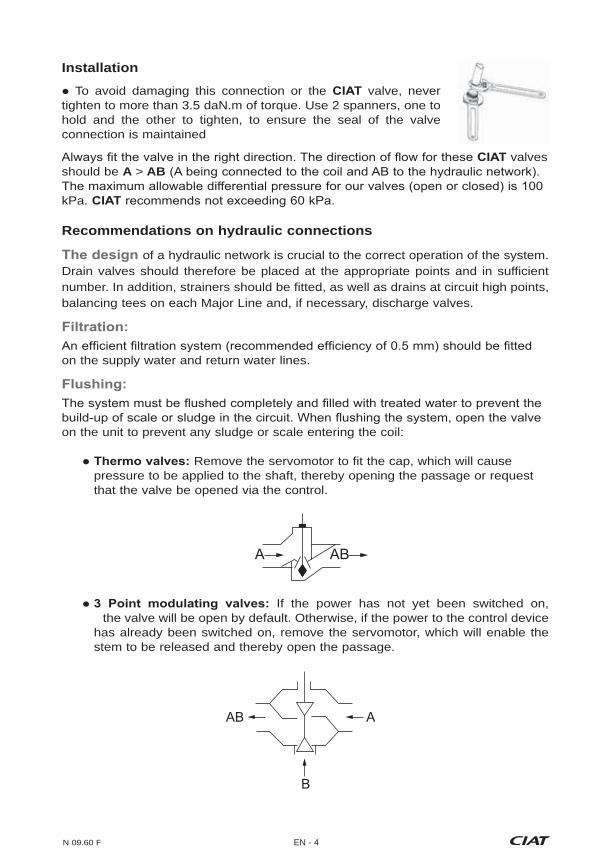
Installation To avoid damaging this connection or the valve, never
tighten to more than 3.5 daN.m of torque. Use 2 spanners, one to hold and the other to tighten, to ensure the seal of the valve connection is maintained
valves should be A > AB
kPa.
Recommendations on hydraulic connections
of a hydraulic network is crucial to the correct operation of the system. Drain valves should therefore be placed at the appropriate points and in sufficient number. In addition, strainers should be fitted, as well as drains at circuit high points, balancing tees on each Major Line and, if necessary, discharge valves.
on the supply water and return water lines.
on the unit to prevent any sludge or scale entering the coil:
Remove the servomotor to fit the cap, which will cause pressure to be applied to the shaft, thereby opening the passage or request that the valve be opened via the control.
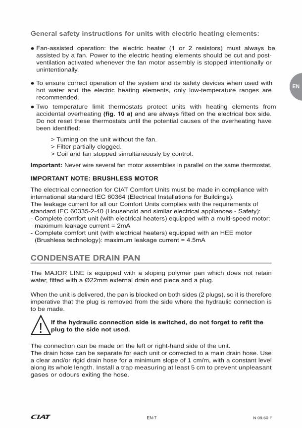
If the power has not yet been switched on, the valve will be open by default. Otherwise, if the power to the control device has already been switched on, remove the servomotor, which will enable the stem to be released and thereby open the passage.
A AB
AB A
B

EN
EN-5 N 09.60 F
Motor Reference 102/104 202/204 302/304 402/404 502/504 602/604
Input power (W)
V5 33 58 88 106 108 135V4 31 41 67 93 94 114V3 29 36 52 80 79 99V2 27 31 42 72 72 88V1 26 27 35 63 63 77
Input current (A)
V5 0.14 0.25 0.38 0.46 47 0.59V4 0.13 0.18 0.29 0.40 0.41 0.50V3 0.13 0.16 0.23 0.35 0.34 0.43V2 0.12 0.13 0.18 0.31 0.31 0.38V1 0.11 0.12 0.15 0.27 0.27 0.33
Drain the coils during commissioning.
To prevent any inopportune opening of the thermo-actuators, the temperature of the air surrounding the thermo-actuators should be kept at no higher than 50°C. This
units
To protect against the risk of condensation when using chilled water, lagging should be placed along the entire lengths of pipes and completely sealed at its ends. When using the water coil and electric heater, we advise against using cross-linked polyethylene
deterioration of the PEX pipe near the unit and cause it to burst. We recommend using
Ensure that the electrical supply is disconnected before working on the unit. Only personnel qualified to perform electrical work may carry out installation and maintenance work.
As indicated on the data plate, the unit must be connected to a single-phase 230V
!
The unit must be earthed. CIAT shall not be liable for incidents resulting from faulty

N 09.60 F EN - 6
Circuit diagrams for customer applications should be based on the diagrams supplied: Unit wiring for 2-pipe or 4-pipe systems . .
For a P>3000 W version, please contact us. recommends using a system that controls the unit in relation to the temperature of the water (to actuate the
Disconnect the unit from the electrical power supply.
Remove the casing .
- To open a connection point, insert the screwdriver fully.- Insert the cable while holding the screwdriver.
The Major Line has a 5-speed motor, all connected to the unit's terminal. To optimise the performance of the unit, it is possible to adapt the 3 on-site customer speeds directly on the unit.
V3, V2, V1 for hotel rooms with stringent acoustic constraints
V4, V3, V1 for
V5, V4, V2 for NCH units with high available pressure
PEPE
Ph
NN
NV1V2
V3MV4V5
6
Ph
- Speed
EN
EN-7 N 09.60 F
assisted by a fan. Power to the electric heating elements should be cut and post-ventilation activated whenever the fan motor assembly is stopped intentionally or unintentionally.
To ensure correct operation of the system and its safety devices when used with hot water and the electric heating elements, only low-temperature ranges are recommended.
Two temperature limit thermostats protect units with heating elements from accidental overheating Do not reset these thermostats until the potential causes of the overheating have been identified:
> Turning on the unit without the fan. > Filter partially clogged. > Coil and fan stopped simultaneously by control.
Never wire several fan motor assemblies in parallel on the same thermostat.
The electrical connection for CIAT Comfort Units must be made in compliance with
The leakage current for all our Comfort Units complies with the requirements of
The MAJOR LINE is equipped with a sloping polymer pan which does not retain
imperative that the plug is removed from the side where the hydraulic connection is to be made.
The connection can be made on the left or right-hand side of the unit.The drain hose can be separate for each unit or corrected to a main drain hose. Use a clear and/or rigid drain hose for a minimum slope of 1 cm/m, with a constant level along its whole length. Install a trap measuring at least 5 cm to prevent unpleasant
!
N 09.60 F EN - 8
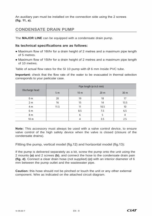
The can be equipped with a condensate drain pump.
of 5 metres.
of 10 metres.
Table of actual flow rates for the SI 10 pump with Ø 6 mm Inside PVC tube.
check that the flow rate of the water to be evacuated in thermal selection corresponds to your particular case.
Discharge headPipe length (ø in.6 mm)
5 m 10 m 20 m 30 m
0 m 20 19 18 172 m 16 15 14 13.54 m 11.5 11 10.5 106 m 8.5 7.5 6.58 m 6 5 4
10 m 4 3.5 2.5
This accessory must always be used with a valve control device, to ensure valve control of the high safety device when the valve is closed (closure of the
If the pump is delivered separately as a kit, screw the pump onto the unit using the 2 mounts and 2 screws , and connect the hose to the condensate drain pain
with an interior diameter of 6 mm between the pump outlet and the wastewater pipe.
component. Wire as indicated on the attached circuit diagram.
EN
EN-9 N 09.60 F
The unit must be serviced periodically between the heating and cooling seasons. In particular,
Disconnect the electrical and hydraulic supplies to the unit before
towards the bottom, freeing it from the runners.
Removing the filter via the lower section of the unit: Swivel the runners and slide the filter towards you, freeing it from the runners.
by
pulling it upwards.
To remove the filter, swivel the runners and release the filter by pulling it towards you.
lock them.
from its housing.
unit is installed and its operating conditions.
!
!

N 09.60 F EN - 10
switched off.
Remove the motor/turbine assembly from the unit
To reassemble the fan motor assembly, perform these steps in reverse order.
clean them using a vacuum cleaner, taking care to ensure they are not damaged. No special maintenance is required for the electric motor.
The condensate drain pan must be kept clean. Clean the plastic pan and its
Cleaning must be carried out with the pan removed, by unscrewing the 2 side screws and the 2 front screws from the pan .
A clean coil is crucial to the efficiency of the unit. If necessary, clean the coil with a vacuum cleaner.
If the coil must be disassembled on account of a leak:
Disconnect the water coil and the condensate drain.
between the unit's support feet.
The condensate pan can be removed without having to remove the coil.
EN
EN-11 N 09.60 F
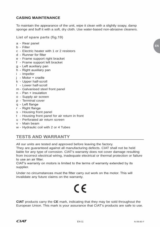
To maintain the appearance of the unit, wipe it clean with a slightly soapy, damp sponge and buff it with a soft, dry cloth. Use water-based non-abrasive cleaners.
a - Rear panelb - Filterc - Electric heater with 1 or 2 resistors
e - Frame support right bracketf - Frame support left bracket
i - Impeller
k - Upper half-scrolll - Lower half-scrollm - Galvanised steel front panel
o - Supply air screenp - Terminal cover
s - Housing front panelt - Housing front panel for air return in frontu - Perforated air return screenv - Main beamw - Hydraulic coil with 2 or 4 Tubes
All our units are tested and approved before leaving the factory.They are guaranteed against all manufacturing defects. CIAT shall not be held liable for any type of corrosion. CIAT's warranty does not cover damage resulting from incorrect electrical wiring, inadequate electrical or thermal protection or failure
supplier.
invalidate any future claims on the warranty.
products carry the CE mark, indicating that they may be sold throughout the European Union. This mark is your assurance that CIAT's products are safe to use.
N 09.60 F DE-1
Das Unternehmen dankt Ihnen für den Erwerb des Major Line, der hoffentlich Ihre Erwartung erfüllen wird. Für einen einwandfreien Betrieb müssen alle
geltenden Gesetzen und Vorschriften montiert werden. Die Wartung des Major Line muss unter Beachtung der in der vorliegenden Anleitung angegebenen Empfehlungen durchgeführt werden.
Korrespondenz anzugeben sind.
der Annahme zu kontrollieren.
empfangenen Kollis anzugeben.
vermerkt und dieser dann unterzeichnet werden.
Vorbehalte jeglicher Art sind dem Transportunternehmen innerhalb von 3
nicht anerkannt. Der Kunde muss daher die Waren in Anwesenheit des Anlieferers
vermerkt wurden.
2 - Ventilator3 - Zugang Motorklemmkasten4 - Monoblock-Kondensatauffangwanne
Isolierung durch PSE Platte5 - Kondensatabführung Ø 22mm
7 - Befestigungsösen zur Wand bzw. Deckenbefestigung
9 - Entlüftungsschraube10 - Schraube zur Registerentleerung
1 - Zuluftgitter2 - Zugang Regelung (Regelung
4 - Abdeckblech vorne aus lackiertem Stahlblech RAL 9010
5 - Rückluftgitter aus Lochblech gültig für Ausführung mit Rückluftgitter auf der Vorderseite.
DE
DE-2 N 09.60 F
Tragen Sie zu Ihrer eigenen Sicherheit Schutzhandschuhe beim Transport!
und in der Originalverpackung aufbewahrt, damit es vor Kratzern geschützt ist.
anheben.
Beide Schnellverschlussschrauben entfernen und das Gitter abnehmen. Dadurch wird der Zugang zu den beiden Schnellverschlussschrauben des
und das
Horizontales Modell
Die Metall-Unterlegscheibe nicht verwenden.

N 09.60 F DE-3
Vertikales Modell Befestigung an der Wand mit 4 Schrauben
Sicherstellen, dass im Fall einer Rückluftführung ohne Kanal an der
Falls eine Regelung mit Raumthermostat vorgesehen ist, darf dieser nicht
Ideal ist die Anbringung auf einer Innenwand in einem Boden-Abstand von 150 cm.
Befestigung mit 2 Blechschrauben Ø 5.53
- Die 4 Befestigungsbleche mit 4 Blechschrauben Ø 3.93 und 4 Kunststoffschrauben Ø 4 anbringen.
(je
Flachbundmuttern mit O-Ring-Dichtung (von
In jedem Fall muss die Wasserzirkulation in den Registern mit Eintritt unten und Austritt oben erfolgen.
: Das Ventil und die mitgelieferte Dichtung direkt auf die
- 2 Wegeventil 2 Leitersystem - 2 Wegeventil 4 Leitersystem
dem Einbau des Ventils montieren: - 4 Wegeventil 2 Leitersystem - 4 Wegeventil 4 Leitersystem
!

DE
DE-4 N 09.60 F
A AB
Installation Um den Anschluss bzw. das Ventil von nicht zu
betragen. Um die Dichtigkeit des Ventilanschlusses zu
einen zum Anziehen.Die Montagerichtung des Ventils beachten. Für die Ventile von gilt die
A > AB
reibungslosen Betrieb der Anlage. Es sind Ablassventile an den richtigen Positionen und in ausreichender Anzahl sowie Schlamm-Absetztöpfe und Entlüftungen am
zum Ausgleich und Überdruckventile angebracht werden, wenn nötig.
und -rückleitung vorzusehen.
Die gesamte Anlage und die Leitungen müssen vor der Inbetriebnahme gespült werden. Das Wasser ist entsprechend zu behandeln, um eine Verschmutzung des
Ablagerung von Schlamm und Unreinheiten im Register zu vermeiden:
Den Stellmotor der Ventile abnehmen, um den Stopfen
Regelung ausgegeben werden.
Falls noch kein Strom eingeschaltet wurde, befindet
Regelung bereits eingeschaltet wurde, den Stellmotor entfernen, wodurch die Welle frei wird und der Durchgang geöffnet wird.
AB A
B
N 09.60 F DE-5
Die Register bei der Inbetriebnahme entlüften.
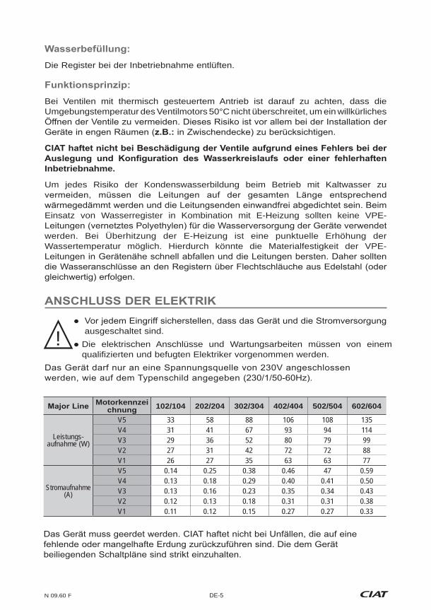
Bei Ventilen mit thermisch gesteuertem Antrieb ist darauf zu achten, dass die Umgebungstemperatur des Ventilmotors 50°C nicht überschreitet, um ein willkürliches
Inbetriebnahme.
Um jedes Risiko der Kondenswasserbildung beim Betrieb mit Kaltwasser zu
Einsatz von Wasserregister in Kombination mit E-Heizung sollten keine VPE-
werden. Bei Überhitzung der E-Heizung ist eine punktuelle Erhöhung der Wassertemperatur möglich. Hierdurch könnte die Materialfestigkeit der VPE-
ausgeschaltet sind.
Die elektrischen Anschlüsse und Wartungsarbeiten müssen von einem qualifizierten und befugten Elektriker vorgenommen werden.
!
Motorkennzei 102/104 202/204 302/304 402/404 502/504 602/604
Leistungs-aufnahme (W)
V5 33 58 88 106 108 135V4 31 41 67 93 94 114V3 29 36 52 80 79 99V2 27 31 42 72 72 88V1 26 27 35 63 63 77
Stromaufnahme (A)
V5 0.14 0.25 0.38 0.46 47 0.59V4 0.13 0.18 0.29 0.40 0.41 0.50V3 0.13 0.16 0.23 0.35 0.34 0.43V2 0.12 0.13 0.18 0.31 0.31 0.38V1 0.11 0.12 0.15 0.27 0.27 0.33
DE
DE-6 N 09.60 F
.
. Für eine Leistung P>3000 W, fragen Sie bitte bei uns nach.
E-Heizung.
Die Stromversorgung des Geräts abtrennen.
Anschlusskastendeckels entfernen.
Die Verkabelung unbedingt mittels Schraubendreher durchführen :
- Den Schraubendreher gedrückt halten und das Kabel einführen.- Den Schraubendreher wieder entfernen, auf diese Weise ist ein sicherer Kontakt
die 3 kundenseitig verfügbaren Geschwindigkeitsstufen direkt an die Klemmleiste geschaltet werden.
V3, V2, V1 für Hotelzimmer hohen Ansprüchen an das
V4, V3, V1 für
V5, V4, V2 für NCH
verfügbaren Druck
PEPE
Ph
NN
NV1V2
V3MV4V5
6
Ph
- langsamer
N 09.60 F DE-7
Für den reibungslosen Betrieb der Warmwasserproduktion und der E-Heizungen sollten nur Niedertemperaturen zum Einsatz kommen, damit Sicherheitseinrichtungen einwandfrei arbeiten können.
Zwei eingebaute Temperaturbegrenzungsthermostate
die Überhitzung ausgelöst hat rückgesetzt werden, zum Beispiel:
> Einschalten ohne Ventilator. > Verschmutzung des Filters. > Regelung, schaltet E-Heizung und Ventilator gleichzeitig ab.
Es dürfen niemals mehrere Motoren der Klimakonvektoren parallel am gleichen Thermostat geschaltet werden.
Wasseranschlusses entfernt werden.
Sammelleitung erfolgen. Zur Ableitung eine transparente, starre Leitung mit
verwenden. Einen Siphon von mindestens 5 cm vorsehen, um einen Rückstau von Gasen oder unangenehmen Gerüchen zu vermeiden.
!
DE
DE-8 N 09.60 F
anbringen
kann mit einer Kondenswasserpumpe ausgerüstet werden.
von 10 m.
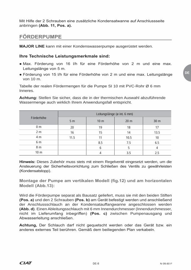
Tabelle der realen Fördermengen für die Pumpe SI 10 mit PVC-Rohr Ø 6 mm Inneres.
Stellen Sie sicher, dass die in der thermischen Auswahl abzuführende Wassermenge auch wirklich Ihrem Anwendungsfall entspricht.
FörderhöheLeitungslänge (ø int. 6 mm)
5 m 10 m 20 m 30 m
0 m 20 19 18 172 m 16 15 14 13.54 m 11.5 11 10.5 106 m 8.5 7.5 6.58 m 6 5 410 m 4 3.5 2.5
Dieses Zubehör muss stets mit einem Regelventil eingesetzt werden, um die
Wird die Förderpumpe separat als Bausatz geliefert, muss sie mit den beiden Stiften und den 2 Schrauben
der Anschlussschlauch an der Kondensatauffangwanne angeschlossen werden . Einen Ableitungsschlauch mit 6 mm Innendurchmesser (Innendurchmesser,
zwischen Pumpenausgang und

N 09.60 F DE-9
und Klimatisierung vorzusehen. Dies gilt insbesondere für alle Teile, die leicht
Vertikales Modell
Filter zu sich schieben und aus den Schienen führen.
Vertikales Modell Die Schienen ausklappen und den Filter entfernen , indem
dieser nach oben herausgezogen wird.
Die Schienen ausklappen, den Filter zu sich schieben und aus den Schienen herausziehen.
einrasten.
Die beiden Schnellverschlussschrauben drehen, das Gitter abschwenken und den Filter aus seiner Aufnahme entfernen.
festlegen zu können. Die Intervalle können je nach Raum und Installationsbedingungen sehr unterschiedlich sein.
!
!

DE
DE-10 N 09.60 F
Zum Einbau in umgekehrter Ausbaureihenfolge vorgehen.
Wartung.
Die Kondensatwanne muss stets sauber gehalten werden. Die Kunststoffwanne und die Tüllen können mit einem milden Reinigungsmittel und Wasser komplett gereinigt werden.
Zur Reinigung die Kunststoffwanne entfernen, indem die beiden seitlichen und die beiden vorderen Schrauben der Kunststoffwanne herausgedreht werden .
Ein sauberes Register ist ein entscheidender Faktor für die Aufrechterhaltung der
Bei einem Leck kann das Register wie folgt ausgebaut werden:
Wasserregister und Kondensatableitung abklemmen.
Es ist möglich, die Kondensatauffangwanne zu entnehmen, ohne den
N 09.60 F DE-11
Reiniger abgewaschen und mit einem weichen Tuch getrocknet werden. Keine aggressiven Reinigungsmittel oder Scheuermittel verwenden.
a - Paneel hintenb - Filter
d - Gleitschiene für Filter
g - Zusatzwanne linksh - Zusatzwanne rechtsi - Turbine
m - Paneel vorne, Stahlblech verzinkt
o - Ausblasgitterp - Abschlussverkleidungq - Flansch linksr - Flansch rechts
u - Rückluftgitter aus Lochblech
w - Wasserregister, 2 Rohre oder 4 Rohre
die elektrischen Anschlüsse falsch angeschlossen, der Motor falsch abgesichert oder
Motorherstellers.
Mit der CE-Kennzeichnung erfüllt die Bestimmungen der -Richtlinie, so dass
ES-1 N 09.60 F
ES
El quede plenamente satisfecho con este producto. Para garantizar su correcto
cuenta las recomendaciones indicadas en el presente manual.
El equipo se entrega embalado y etiquetado con todas las referencias para que se
estado de la mercancía.
paquetes recibidos.
En caso observarse daños en los equipos, el cliente deberá describir obligatoriamente en el albarán de entrega los daños detectados en presencia
presencia del transportista. En el momento de la entrega, las eventuales reservas deben indicarse de forma precisa.
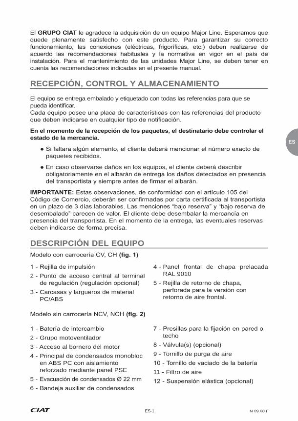
2 - Punto de acceso central al terminal
3 - Carcasas y largueros de material PC/ABS
4 - Panel frontal de chapa prelacada RAL 9010
5 - Rejilla de retorno de chapa,
retorno de aire frontal.
2 - Grupo motoventilador3 - Acceso al bornero del motor4 - Principal de condensados monobloc
en ABS PC con aislamiento reforzado mediante panel PSE
5 -
techo
9 - Tornillo de purga de aire
11 - Filtro de aire
N 09.60 F ES-2
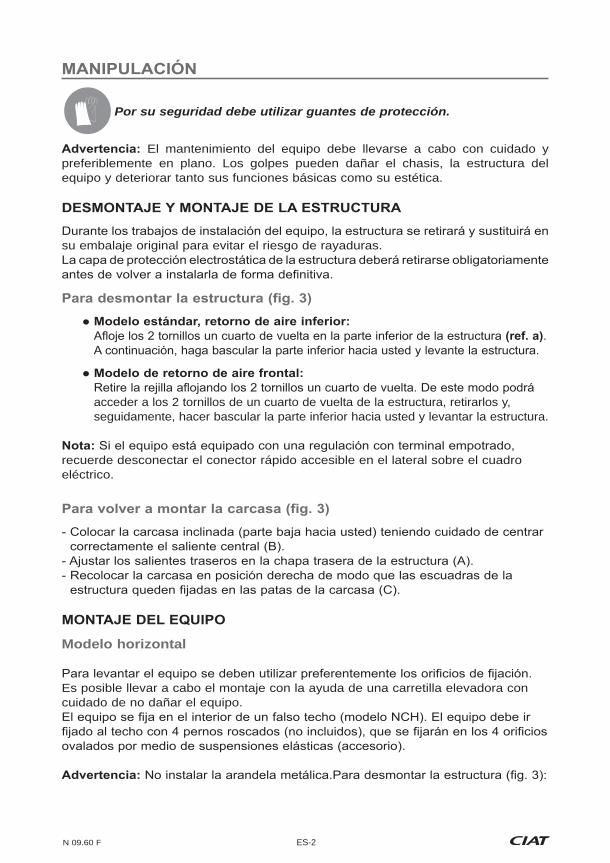
Por su seguridad debe utilizar guantes de protección.
El mantenimiento del equipo debe llevarse a cabo con cuidado y preferiblemente en plano. Los golpes pueden dañar el chasis, la estructura del equipo y deteriorar tanto sus funciones básicas como su estética.
su embalaje original para evitar el riesgo de rayaduras.
.
acceder a los 2 tornillos de un cuarto de vuelta de la estructura, retirarlos y, seguidamente, hacer bascular la parte inferior hacia usted y levantar la estructura.
recuerde desconectar el conector rápido accesible en el lateral sobre el cuadro eléctrico.
Modelo horizontal
Es posible llevar a cabo el montaje con la ayuda de una carretilla elevadora con cuidado de no dañar el equipo.
ES-3 N 09.60 F
ES
Fijado a la pared con 4 tornillos Fijado al el suelo con las patas de apoyo o la caja de retorno de aire (modelo
Todos los equipos deben estar perfectamente nivelados. Asegúrese que la parte posterior del equipo, en caso de retorno sin conducto, esté
.
desprenda calor, sino más bien en un tabique interior a 150 cm del suelo.
- Coloque la unidad Major Line en plano sobre la caja de retorno de aire
con 4 tornillos para chapa Ø 3,93 y 4 tornillos para plástico Ø 4
misma
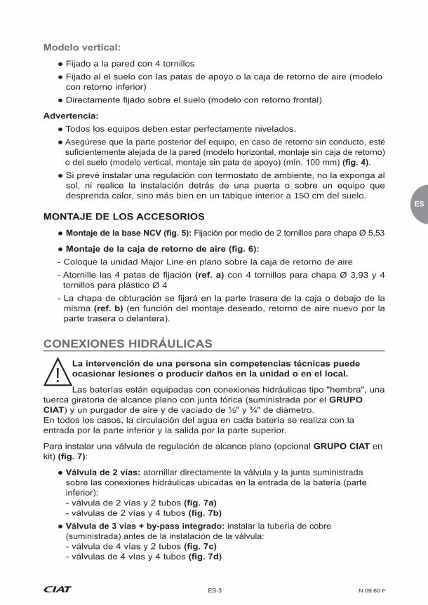
ocasionar lesiones o producir daños en la unidad o en el local.
entrada por la parte inferior y la salida por la parte superior.
en :
atornillar directamente la válvula y la junta suministrada
!
N 09.60 F ES-4
Instalación
, no aplique un par de apriete superior a 3,5 daN.m. Utilice 2 llaves,
Respete el sentido de montaje correcto de la válvula. En las válvulas del A > AB
recomienda no sobrepasar los 60 kPa.
Recomendaciones hidráulicas
El diseño de las redes hidráulicas es un factor determinante para el correcto
número suficiente válvulas de vaciado, colectores de barro, purgadores en la parte superior del circuito, piezas de equilibrado en T en cada Major Line y válvulas de descarga, si es preciso.
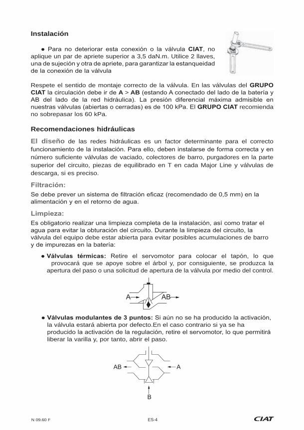
válvula del equipo debe estar abierta para evitar posibles acumulaciones de barro
provocará que se apoye sobre el árbol y, por consiguiente, se produzca la apertura del paso o una solicitud de apertura de la válvula por medio del control.
A AB
la válvula estará abierta por defecto.En el caso contrario si ya se ha
liberar la varilla y, por tanto, abrir el paso.
AB A
B
ES-5 N 09.60 F
ES
En el caso de las válvulas equipadas con motores térmicos, procure que la
evitar cualquier riesgo de apertura inesperada. Riesgo que debe tenerse en cuenta principalmente en el caso de equipos instalados en espacios cerrados (
válvulas debido a errores en el diseño de la red de alimentación hidráulica o en la puesta en marcha.
deben estar cualificadas para llevar a cabo con total seguridad instalaciones y labores de mantenimiento.
!
Referencia motor 102/104 202/204 302/304 402/404 502/504 602/604
Potencia absorbida (W)
V5 33 58 88 106 108 135V4 31 41 67 93 94 114V3 29 36 52 80 79 99V2 27 31 42 72 72 88V1 26 27 35 63 63 77
Intensidad absorbida (A)
V5 0.14 0.25 0.38 0.46 47 0.59V4 0.13 0.18 0.29 0.40 0.41 0.50V3 0.13 0.16 0.23 0.35 0.34 0.43V2 0.12 0.13 0.18 0.31 0.31 0.38V1 0.11 0.12 0.15 0.27 0.27 0.33
Es obligatorio conectar a tierra el equipo. Rechazamos toda responsabilidad en caso de
esquema adjunto al equipo.

N 09.60 F ES-6
V3, V2, V1 para habitaciones de hotel con una
importante
V4, V3, V1 para oficinas de alto
standing
V5, V4, V2 para dispositivos NCH
disponible importante
PEPE
Ph
NN
NV1V2
V3MV4V5
6
Ph
- Rápido
Para aplicaciones del cliente, el esquema eléctrico deberá elaborarse a partir de los esquemas suministrados:
El
Para acceder al bornero eléctrico:Desconecte el equipo de la alimentación eléctrica.
Desmonte la estructura cuadro eléctrico .
Utilizar obligatoriamente un destornillador en el cableado :
- Introducir el cable manteniendo el destornillador.
manera segura
Major Line dispone de un motor de 5 velocidades, todas ellas llevadas al bornero del equipo. Para optimizar el rendimiento del equipo, es posible adaptar las 3 velocidades del cliente en obra directamente al bornero.
Consejos para un cableado por defecto de las 3 velocidades en obra. (En la
ES-7 N 09.60 F
ES
o inesperada del grupo motoventilador debe implicar obligatoriamente el corte
garantizar que el funcionamiento de nuestros dispositivos de seguridad sea el adecuado.
resistencias está garantizada por medio de los 2 termostatos del limitador de
eventual rearme de los termostatos se llevará a cabo únicamente después de
No conecte nunca varios motores de ventiloconvector al mismo termostato en paralelo.
cabo conforme a la norma internacional de referencia CEI 60364 (Instalaciones
La corriente de fuga de todas nuestras unidades de confort es conforme a las
olvide volver a colocar el tapón en el otro lado.!
N 09.60 F ES-8
evitar posibles emisiones de olores desagradables.
de 2 tornillos
.
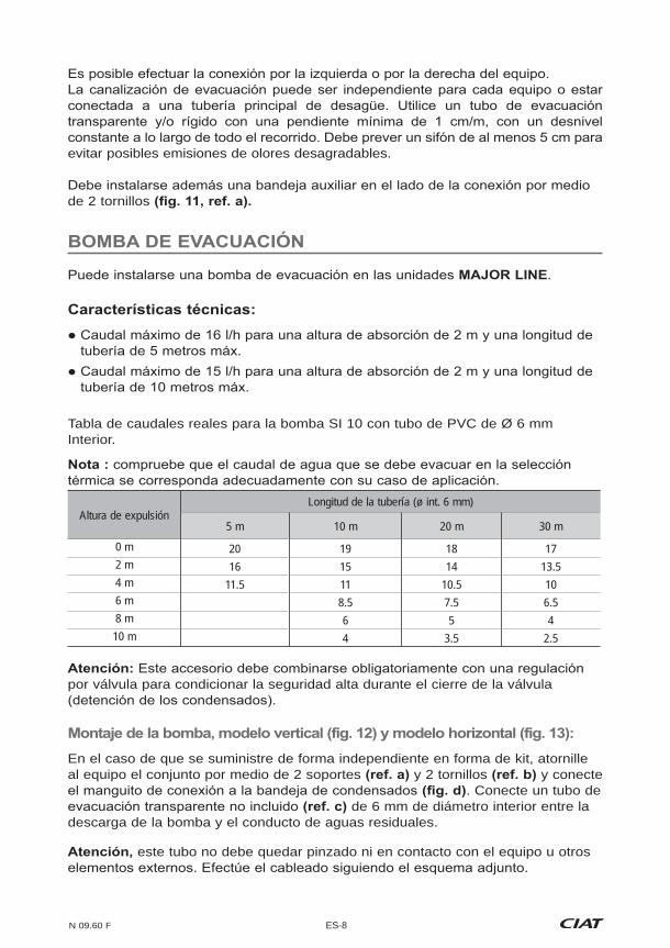
Tabla de caudales reales para la bomba SI 10 con tubo de PVC de Ø 6 mm Interior.
Altura de expulsiónLongitud de la tubería (ø int. 6 mm)
5 m 10 m 20 m 30 m
0 m 20 19 18 172 m 16 15 14 13.54 m 11.5 11 10.5 106 m 8.5 7.5 6.58 m 6 5 410 m 4 3.5 2.5
por válvula para condicionar la seguridad alta durante el cierre de la válvula
En el caso de que se suministre de forma independiente en forma de kit, atornille al equipo el conjunto por medio de 2 soportes y 2 tornillos y conecte
. Conecte un tubo de de 6 mm de diámetro interior entre la
descarga de la bomba y el conducto de aguas residuales.
este tubo no debe quedar pinzado ni en contacto con el equipo u otros

ES-9 N 09.60 F
ES
esté desconectado cortando la alimentación eléctrica e hidráulica.
Modelo horizontal
.
él hacia arriba.
Modelo horizontal
bloquearlas.
Gire los 2 tornillos de ¼ de vuelta , haga pivotar la rejilla y retire el filtro de su alojamiento.
temporada de funcionamiento. En el caso de un mantenimiento más frecuente, el
!
!
N 09.60 F ES-10
haya desconectado.
Retire el grupo motor/turbina del equipo
no requiere ningún mantenimiento particular.
La bandeja de condensados tiene que estar limpia. Se puede limpiar toda la bandeja de plástico y sus tomas con productos detergentes a base de agua no abrasivos.
Esta limpieza puede llevarse a cabo retirando la bandeja tras desatornillar los 2 tornillos laterales y los 2 tornillos frontales de la misma .
aspirador.
su emplazamiento entre las patas de apoyo del equipo.
Ahora es posible desmontar la bandeja de condensados sin necesidad de
ES-11 N 09.60 F
ES
Para proteger la estética del equipo, pasar una esponja húmeda ligeramente enjabonada y sacar brillo con un trapo suave y seco. Utilizar productos detergentes a base de agua no abrasivos.
a - Panel traserob - Filtro
e - Pie derecho de soporte del chasisf - Pie izquierdo de soporte del chasis
i - Turbina
k - Semivoluta superiorl - Semivoluta inferiorm - Panel delantero de acero galvanizado
o - Rejilla de descargap - Cubrebornesq - Brida izquierdar - Brida derecha
u - Rejilla perforada de retorno de airev - Larguero
proveedor.
El instalador no debe intervenir en el motor en ningún caso. De lo contrario,
cuenta con el marcado CE

N 09.60 F IT-1
vi ringrazia per aver acquistato l'unità Major Line che, si augura, possa rispondere pienamente alle vostre aspettative. Per il corretto funzionamento dell'unità, i collegamenti
paese di installazione. Per la manutenzione ordinaria dell'unità Major Line si dovrà tenere conto delle raccomandazioni indicate nella presente guida.
L'apparecchio viene fornito etichettato sull'imballaggio con tutte le
Su ogni apparecchio è apposta una targhetta che riporta i riferimenti del prodotto da indicare su tutta la corrispondenza.
Se mancano dei componenti, il cliente deve indicare il numero esatto dei colli ricevuti.
Se si riscontrano dei danni sugli apparecchi, il cliente deve indicare sulla bolla i danni constatati alla presenza dell'addetto alla consegna e solo
I reclami, come indicato nell'articolo 105 del Codice del Commercio,
giorni lavorativi. Le citazioni "con riserva" o "con riserva di disimballo" non hanno alcun valore. Il cliente deve disimballare la merce alla presenza del trasportatore. Sono necessarie riserve precise alla consegna.
1 - Griglia di mandata2 - Punto d'accesso centrale al
terminale di regolazione (regolazione
3 - Flange e longheroni in materiale ABS PC
4 - Pannello anteriore in lamiera preverniciata RAL 9010
5 - Griglia di ripresa in lamiera perforata per la versione Ricircolo aria anteriore.
1 - Batteria di scambio2 - Gruppo moto-ventilatore3 - Accesso scatola motore4 - Vasca principale per lo scarico
condensa - monoblocco in ABS PC con isolamento rinforzato dal pannello PSE
5 - Scarico condensa Ø22mm6 - Vasca supplementare dello scarico
condensa
9 - Viti di spurgo aria10 - Viti di scarico della batteria11 - Filtro aria
Modello Senza Carter NCV, NCH
Modello con Carter CV, CH

IT
IT-2 N 09.60 F
Per la vostra sicurezza, indossate guanti protettivi!
L’apparecchio deve essere spostato con cura e preferibilmente in piano. Gli urti possono deformare il telaio, la struttura dell'apparecchio e danneggiarne le funzioni primarie e la sua estetica.
Durante gli interventi di installazione dell'apparecchio, il mantello verrà rimosso e
La pellicola protettiva elettrostatica del mantello dovrà essere rimossa tassativamente
Modello standard, ricircolo aria inferiore:
quindi verso di sé la parte inferiore e sollevare il mantello.
Modello di ricircolo aria anteriore: Togliere la griglia svitando le 2 viti di ¼ di giro. Questo consente di accedere alle 2 viti del telaio, svitarle e toglierle, di spostare quindi verso di sé la parte inferiore e sollevare il telaio.
se l'apparecchio dispone di una regolazione con terminale incassato, scollegare il connettore rapido accessibile dal lato superiore della scatola elettrica.
- Raddrizzare il mantello in posizione verticale in modo che gli angolari del telaio
possibile effettuare il montaggio usando un carrello elevatore facendo attenzione a non danneggiare l'apparecchio.
Non inserire la rondella metallica.
N 09.60 F IT-3
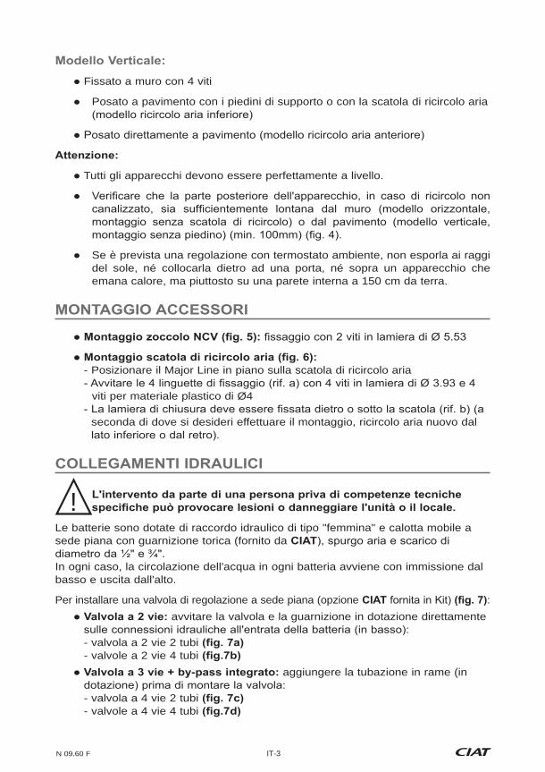
Fissato a muro con 4 viti
Posato a pavimento con i piedini di supporto o con la scatola di ricircolo aria
Tutti gli apparecchi devono essere perfettamente a livello.
Se è prevista una regolazione con termostato ambiente, non esporla ai raggi del sole, né collocarla dietro ad una porta, né sopra un apparecchio che emana calore, ma piuttosto su una parete interna a 150 cm da terra.
- Posizionare il Major Line in piano sulla scatola di ricircolo aria
viti per materiale plastico di Ø4
seconda di dove si desideri effettuare il montaggio, ricircolo aria nuovo dal
Le batterie sono dotate di raccordo idraulico di tipo "femmina" e calotta mobile a sede piana con guarnizione torica (fornito da
In ogni caso, la circolazione dell'acqua in ogni batteria avviene con immissione dal basso e uscita dall'alto.
Per installare una valvola di regolazione a sede piana (opzione : avvitare la valvola e la guarnizione in dotazione direttamente
- valvola a 2 vie 2 tubi - valvole a 2 vie 4 tubi
aggiungere la tubazione in rame (in
- valvola a 4 vie 2 tubi - valvole a 4 vie 4 tubi
!

IT
IT-4 N 09.60 F
Impianto Per evitare di deteriorare questo raccordo o la valvola , non
applicare una coppia di serraggio superiore a 3,5 daN.m.
garantire la tenuta del raccordo della valvola
Rispettare il senso di montaggio della valvola. Su queste valvole CIAT la circolazione avviene in direzione A > AB (con A collegato sul lato batteria e AB sul
Raccomandazioni idrauliche
delle reti idrauliche è un fattore determinate per il corretto funzionamento dell'impianto. Per tale ragione prevedere delle valvole di scarico correttamente posizionate e in numero sufficiente, dei raccogli fango, degli sfiati installati in posizione alta sul circuito, dei profilati a T di equilibratura su ogni Major Line e delle valvole di scarico, se necessario.
sull'alimentazione di acqua e sulle acque di ritorno.
modo da evitare l'incrostamento del circuito. Durante il risciacquo del circuito, la valvola del vostro apparecchio deve essere aperta per evitare ogni accumulo di sedimenti e di impurità nella batteria:
Valvole termiche: togliere il servomotore per applicare il tappo. Questa operazione provocherà la pressione sull'albero quindi l'apertura del foro oppure richiedere l'apertura della valvola espletando l'apposito comando.
Valvole modulanti a 3 Punti: se l'allacciamento non è ancora stato eseguito, la valvola si aprirà automaticamente. In caso contrario, se la regolazione è già stata allacciata, togliere il servomotore. Questa operazione consentirà di disimpegnare l'asta e quindi l'apertura del foro.
A AB
AB A
B
Spurgare le batterie al momento della messa in servizio.

N 09.60 F IT-5
Nel caso di valvole dotate di motori termici, controllare che la temperatura dell'area attorno al motore della valvola non superi i 50°C per evitare qualsiasi rischio di apertura intempestiva. Rischio da considerare soprattutto per gli apparecchi
messa in servizio.
con acqua fredda, sarà necessario isolare termicamente le canalizzazioni sulla loro intera lunghezza, assicurandosi che la tenuta alle estremità sia perfetta. Per impianti con batteria acqua e batteria elettrica, sconsigliamo l'utilizzo di tubi di
surriscaldamento della batteria elettrica, è possibile un aumento puntuale della temperatura. Tale aumento può far calare molto rapidamente le caratteristiche del
Prima di un intervento, escludere l'alimentazione elettrica all'apparecchio. Il personale che interviene sui collegamenti elettrici deve essere abilitato a realizzare in assoluta sicurezza installazione e manutenzione.
Alimentare l'unità solo con una tensione di 230V, come indicato sulla targhetta
Riferimentomotore 102/104 202/204 302/304 402/404 502/504 602/604
Potenza assorbita (W)
V5 33 58 88 106 108 135V4 31 41 67 93 94 114V3 29 36 52 80 79 99V2 27 31 42 72 72 88V1 26 27 35 63 63 77
Intensità assorbita (A)
V5 0.14 0.25 0.38 0.46 47 0.59V4 0.13 0.18 0.29 0.40 0.41 0.50V3 0.13 0.16 0.23 0.35 0.34 0.43V2 0.12 0.13 0.18 0.31 0.31 0.38V1 0.11 0.12 0.15 0.27 0.27 0.33
!
La messa a terra dell'apparecchio è obbligatoria. CIAT declina ogni responsabilità per incidenti conseguenti alla mancata messa a terra dell'apparecchio o ad una messa a terra non corretta. Attenersi sempre allo schema fornito con l'apparecchio.
IT
IT-6 N 09.60 F
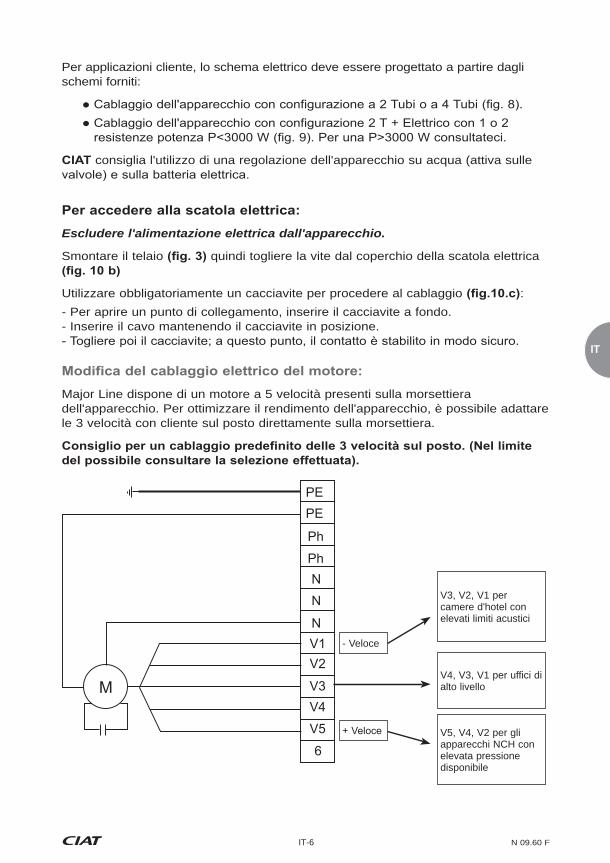
Per applicazioni cliente, lo schema elettrico deve essere progettato a partire dagli schemi forniti:
consiglia l'utilizzo di una regolazione dell'apparecchio su acqua (attiva sulle
Escludere l'alimentazione elettrica dall'apparecchio.
Smontare il telaio quindi togliere la vite dal coperchio della scatola elettrica
Utilizzare obbligatoriamente un cacciavite per procedere al cablaggio :- Per aprire un punto di collegamento, inserire il cacciavite a fondo.- Inserire il cavo mantenendo il cacciavite in posizione.
Major Line dispone di un motore a 5 velocità presenti sulla morsettiera dell'apparecchio. Per ottimizzare il rendimento dell'apparecchio, è possibile adattare le 3 velocità con cliente sul posto direttamente sulla morsettiera.
V3, V2, V1 per camere d'hotel con elevati limiti acustici
V4, V3, V1 per uffici di alto livello
V5, V4, V2 per gli apparecchi NCH con elevata pressione disponibile
PEPE
Ph
NN
NV1V2
V3MV4V5
6
Ph
- Veloce

N 09.60 F IT-7
tassativamente asservita al ventilatore. Lo spegnimento volontario o intempestivo del gruppo moto-ventilatore deve comportare tassativamente il disinserimento dell'alimentazione delle resistenze elettriche e una post-ventilazione.
elettriche, sono raccomandati solo regimi a bassa temperatura al fine di assicurare il corretto funzionamento dei nostri dispositivi di sicurezza.
La protezione dal surriscaldamento accidentale degli apparecchi dotati di resistenze è garantita da 2 termostati limitatori di temperatura posizionati sempre a lato della scatola elettrica. L'eventuale riarmo dei termostati andrà eseguito solo dopo aver individuato le cause del surriscaldamento che ne hanno comportato l'attivazione:
> Messa in tensione senza ventilazione.
> Regolazione che arresta contemporaneamente la batteria e il ventilatore.
Non collegare mai più moto-ventilatori in parallelo sullo stesso termostato.
Il collegamento elettrico delle Unità di comfort CIAT deve essere effettuato in conformità con la norma internazionale di riferimento CEI 60364 (Impianti elettrici
La corrente di fuga di tutte le nostre Unità di comfort è conforme ai requisiti della
Sull'unità MAJOR LINE è installata una vasca in polimero inclinata senza ritenzione d'acqua, dotata di un terminale di scarico di Ø 22mm all'esterno, e di un tappo.
quindi tassativamente il tappo in base al lato del raccordo idraulico scelto.
applicare il tappo nel lato opposto.
Il raccordo può essere effettuato nel lato sinistro o destro dell'apparecchio.La canalizzazione di scarico può essere indipendente per ogni apparecchio oppure collegata ad una tubazione principale di scarico. Utilizzare un tubo di scarico trasparente e/o rigido per una pendenza di almeno 1 cm/m, con un dislivello costante lungo tutto il percorso.
!

IT
IT-8 N 09.60 F
Prevedere un sifone di almeno 5 cm per evitare mandate di gas o di odori sgradevoli.
Una vasca supplementare deve essere montata sul lato del raccordo utilizzando le 2 viti
Sull'unità può essere montata una pompa di scarico.
Portata massima di 16l/h per un'altezza di scarico di 2 metro ed una lunghezza massima della tubazione di 5 metri.
Portata massima di 15l/h per un'altezza di scarico di 2 metro ed una lunghezza massima della tubazione di 10 metri.
Tabella delle capacità reali per la pompa SI 10 con tubo PVC Ø 6 mm interiore.
selezione termica corrisponda correttamente al vostro caso di applicazione.
Altezza di mandataLunghezza della tubazione (ø int. 6 mm)
5 m 10 m 20 m 30 m
0 m 20 19 18 172 m 16 15 14 13.54 m 11.5 11 10.5 106 m 8.5 7.5 6.58 m 6 5 410 m 4 3.5 2.5
Questo accessorio deve essere obbligatoriamente associato ad una
Nel caso in cui questa venga fornita separatamente sotto forma di kit, avvitare l'insieme sull'apparecchio utilizzando 2 supporti e 2 viti , collegare il tubo di raccordo alla vasca di scarico della condensa . Collegare un tubo di scarico trasparente non in dotazione
di 6 mm di diametro interno tra la mandata della pompa e il condotto d'acqua utilizzata.
questo tubo non deve essere stretto o a contatto con l'apparecchio o altro elemento esterno. Cablare seguendo lo schema allegato.
N 09.60 F IT-9
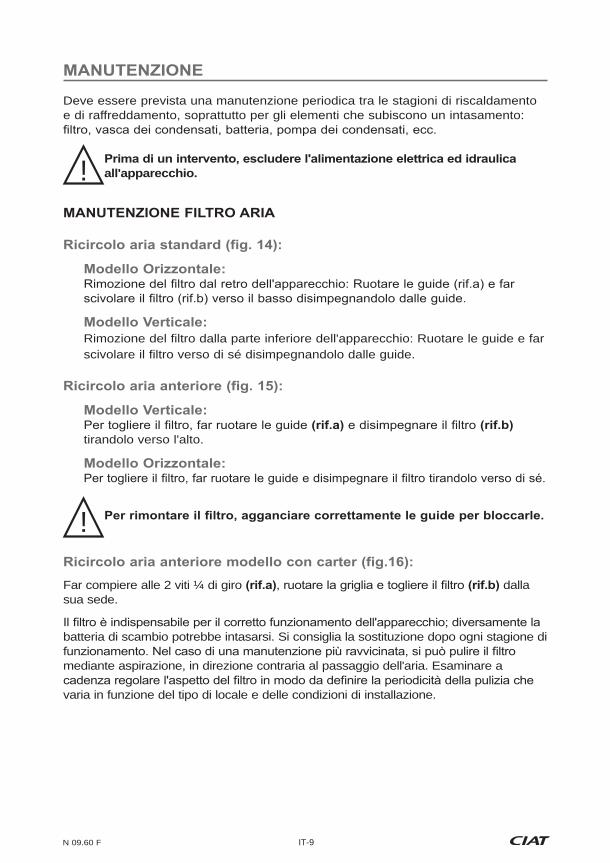
Deve essere prevista una manutenzione periodica tra le stagioni di riscaldamento e di raffreddamento, soprattutto per gli elementi che subiscono un intasamento:
all'apparecchio.
Rimozione del filtro dalla parte inferiore dell'apparecchio: Ruotare le guide e far scivolare il filtro verso di sé disimpegnandolo dalle guide.
tirandolo verso l'alto.
Far compiere alle 2 viti ¼ di giro dalla sua sede.
batteria di scambio potrebbe intasarsi. Si consiglia la sostituzione dopo ogni stagione di
mediante aspirazione, in direzione contraria al passaggio dell'aria. Esaminare a
varia in funzione del tipo di locale e delle condizioni di installazione.
!
!

IT
IT-10 N 09.60 F
l'apparecchio.
Togliere il gruppo motore/turbina dell'apparecchio
Per il rimontaggio, procedere nel senso inverso.
necessario, pulirli con un aspiratore prestando attenzione a non danneggiarli. Il motore elettrico non richiede alcuna manutenzione particolare.
La vasca di scarico della condensa deve rimanere pulita. Una pulizia completa della vasca di plastica e dei suoi manicotti può essere effettuata usando prodotti detergenti a base di acqua non abrasivi.
Questa pulizia può essere effettuata togliendo la vasca, svitandone le 2 viti laterali e
MANUTENZIONE BATTERIA DI SCAMBIO
Lo stato di pulizia della batteria è un fattore determinante per l'elevata resa
Se occorre smontare la batteria in caso di perdita:
Scollegare la batteria acqua e lo scarico della condensa.
Svitare le viti laterali della batteria di scambio disimpegnandola dalla sua sede
tra i piedini di supporto dell'apparecchio.
è possibile smontare la vasca di scarico della condensa senza rimuovere la batteria di scambio.

N 09.60 F IT-11
Per pulire l'involucro dell'apparecchio, passare una spugna umida leggermente
detergenti ad acqua non abrasivi.
a - Pannello posterioreb - Filtroc - Batteria elettrica con 1 o 2 resistenze
e - Piedino destro di supporto per telaiof - Piedino sinistro di supporto per telaiog - Vasca supplementare sinistrah - Vasca supplementare destrai - Turbina
k - Semi-chiocciola superiorel - Semi-chiocciola inferiorem - Pannello anteriore in acciaio galvanizzato
o - Griglia di mandatap - Copriterminaleq - Flangia sinistrar - Flangia destras - Pannello anteriore del mantellot - Pannello anteriore del mantello per ricircolo aria anterioreu - Griglia di ricircolo aria perforatav - Longheronew - Batteria idraulica a 2 Tubi o 4 Tubi
Tutti i nostri apparecchi sono testati e collaudati prima della spedizione.Sono garantiti contro tutti i vizi di fabbricazione. La nostra responsabilità non copre tuttavia eventuali casi di corrosione. I motori non sono garantiti in caso di errore di
La nostra garanzia copre i motori secondo la garanzia del nostro fornitore.
Per nessuna ragione, l'installatore deve intervenire sul motore. In caso contrario,
Il marchio CE autorizza la libera circolazione degli apparecchi in tutto il territorio dell'Unione Europea. Questa marcatura è una garanzia di sicurezza e di protezione delle persone.

NL
NL-1 N 09.60 F
dankt u voor het in haar gestelde vertrouwen door het aanschaffen van een Major Line die, naar wij hopen, aan al uw verwachtingen zal voldoen. Om de goede werking te
uitgevoerd volgens de in het land van de installatie geldende voorschriften. Het onderhoud van uw Major Line moet worden uitgevoerd volgens de aanbevelingen die in deze handleiding staan.
Op het etiket op de verpakking van het apparaat staan alle gegevens waarmee u het kunt
Elk apparaat heeft een typeplaatje met de referenties van het product die u bij eventuele correspondentie altijd moet vermelden.
vermelden.
Indien apparaten zijn beschadigd, is de klant verplicht de geconstateerde schade te vermelden op het ontvangstbewijs in aanwezigheid van de bezorger, en moet de klant het ontvangstbewijs daarna pas ondertekenen.
Deze opmerkingen moeten, overeenkomstig artikel 105 van de Franse wet op de koophandel, binnen 3 werkdagen worden bevestigd door middel van een aangetekend schrijven aan de transporteur. De vermeldingen "onder voorbehoud" en "onder voorbehoud van uitpakken" hebben geen enkele waarde. De klant moet de
zorg gebeuren.
Omkast model CV, CH
1 - Uitblaasrooster2 - Centraal toegangspunt naar de
3 - Flenzen en langsbalken van kunststof ABS PC
4 - Voorpaneel van gelakte plaat, kleur RAL 9010
5 - Aanzuigrooster van geperforeerde plaat voor uitvoering met luchtaanzuiging aan de voorkant.
Niet-omkast model NCV, NCH
1 - Wisselbatterij2 - Ventilatormotorunit3 - Toegang aansluitstrip van de motor4 - Hoofdbak voor condenswater uit één
stuk van ABS PC met versterkte isolatie door paneel van PSE
5 - Condenswaterafvoer Ø 22 mm
7 - Sleufgaten voor bevestiging tegen de muur of aan het plafond
9 - Ontluchtschroef10 - Aftapschroef van de batterij
N 09.60 F NL-2
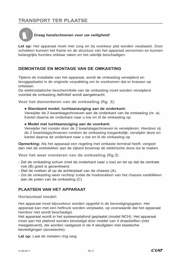
Draag handschoenen voor uw veiligheid!
Het apparaat moet met zorg en bij voorkeur plat worden verplaatst. Door schokken kunnen het frame en de structuur van het apparaat vervormen en kunnen belangrijke functies onklaar raken en het uiterlijk beschadigen.
Tijdens de installatie van het apparaat, wordt de omkasting verwijderd en teruggeplaatst in de originele verpakking om te voorkomen dat er krassen op ontstaan.De elektrostatische beschermfolie van de omkasting moet worden verwijderd
Kantel daarna de onderkant naar u toe en til de omkasting op.
Verwijder het rooster door de 2 kwartslagschroeven te verwijderen. Hierdoor zij
de 2 kwartslagschroeven rondom de omkasting toegankelijk, verwijder deze en kantel daarna de onderkant naar u toe en til de omkasting op.
Als het apparaat een regeling met omkaste terminal heeft, vergeet dan niet de snelstekker aan de zijkant bovenop de elektrische doos los te maken.
- Zet de omkasting weer rechtop zodat de hoekstukken van het chassis vastklikken
Het apparaat moet bijvoorkeur worden opgetild in de bevestigingsgaten. Het apparaat kan met een heftruck worden verplaatst, op voorwaarde dat het apparaat hierdoor niet wordt beschadigd.
moet aan het plafond worden bevestigd door middel van 4 draadstiften (niet
Laat de metalen ring weg.

NL
NL-3 N 09.60 F
Tegen de muur bevestigd met 4 schroeven
Op de vloer geplaatst met steunpoten of luchtaanzuigkamer (model met
Alle apparaten moeten perfect waterpas zijn.
Controleer of de achterkant van het apparaat, indien de aanzuiging niet via een kanaal verloopt, voldoende verwijderd is van de muur (horizontaal model,
.
Bij een regeling met kamerthermostaat mag deze niet in de zon, niet achter een deur, niet boven een apparaat dat warmte afgeeft zijn geplaatst, maar tegen een binnenmuur op 150 cm van de vloer.
Bevestiging met 2 plaatschroeven Ø 5.53 - Plaats de Major Line plat op de luchtaanzuigkamer - Schroef de 4 bevestigingspoten vast met 4 plaatschroeven Ø 3.93 en
4 schroeven voor plastic Ø 4 - De afsluitplaat wordt vastgezet aan de achterkant van de kamer of eronder
(naargelang de gewenste montage, luchtaanzuiging via onder- of
kennis kunnen
De batterijen hebben wateraansluitingen met inwendige schroefdraad en een vlak draagvlak met een O-ring (geleverd door
In alle gevallen circuleert het water in elke batterij van de ingang aan de onderkant naar de uitgang aan de bovenkant.
Voor het installeren van een regelventiel met plat draagvlak (optie :
schroef het ventiel en de meegeleverde afdichting rechtstreeks
- 2-weg ventiel 2 buizen - 2-weg ventielen 4 buizen
voeg de koperen leidingen
!
N 09.60 F NL-4
Installatie
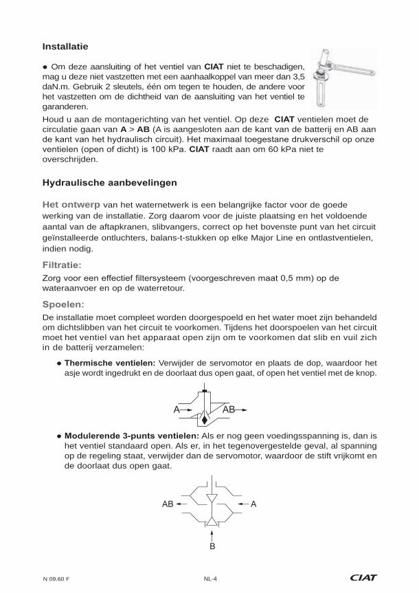
Om deze aansluiting of het ventiel van niet te beschadigen, mag u deze niet vastzetten met een aanhaalkoppel van meer dan 3,5 daN.m. Gebruik 2 sleutels, één om tegen te houden, de andere voor het vastzetten om de dichtheid van de aansluiting van het ventiel te garanderen.Houd u aan de montagerichting van het ventiel. Op deze ventielen moet de circulatie gaan van A > AB (A is aangesloten aan de kant van de batterij en AB aan
raadt aan om 60 kPa niet te overschrijden.
Het ontwerp van het waternetwerk is een belangrijke factor voor de goede werking van de installatie. Zorg daarom voor de juiste plaatsing en het voldoende aantal van de aftapkranen, slibvangers, correct op het bovenste punt van het circuit geïnstalleerde ontluchters, balans-t-stukken op elke Major Line en ontlastventielen, indien nodig.
wateraanvoer en op de waterretour.
De installatie moet compleet worden doorgespoeld en het water moet zijn behandeld om dichtslibben van het circuit te voorkomen. Tijdens het doorspoelen van het circuit moet het ventiel van het apparaat open zijn om te voorkomen dat slib en vuil zich in de batterij verzamelen:
Verwijder de servomotor en plaats de dop, waardoor het asje wordt ingedrukt en de doorlaat dus open gaat, of open het ventiel met de knop.
Als er nog geen voedingsspanning is, dan is het ventiel standaard open. Als er, in het tegenovergestelde geval, al spanning op de regeling staat, verwijder dan de servomotor, waardoor de stift vrijkomt en de doorlaat dus open gaat.
AB A
B
A AB
NL
NL-5 N 09.60 F
Ontlucht de batterijen bij het inbedrijfstellen.
Voor de ventielen met thermische motortjes, moet u erop letten dat de omgeving van de motor van het ventiel niet warmer wordt dan 50 °C om te voorkomen dat het ventiel onterecht opent. Dit gevaar geldt met name voor apparaten in kleine ruimtes (
Om ieder gevaar van condensatie tijdens de werking met gekoeld water te voorkomen, moeten de leidingen over hun gehele lengte worden geïsoleerd met isolatiemateriaal dat ook aan de einden perfect dicht is. Bij toepassingen met waterbatterijen en elektrische batterijen, adviseren wij het gebruik van buizen van gereticuleerd
de elektrische batterij, kan de watertemperatuur kortstondig hoog oplopen. Hierdoor kunnen de eigenschappen van het PER in de buurt van het apparaat snel achteruitgaan waardoor het materiaal kan scheuren. Wij adviseren de batterij op het watercircuit aan
Zorg er voor alle werkzaamheden voor dat het apparaat spanningsloos is door het uitschakelen van de elektrische voeding.
Personen die werken aan de elektrische aansluitingen moeten beschikken over de noodzakelijke vakkennis voor het veilig kunnen werken aan en onderhouden van de installatie.
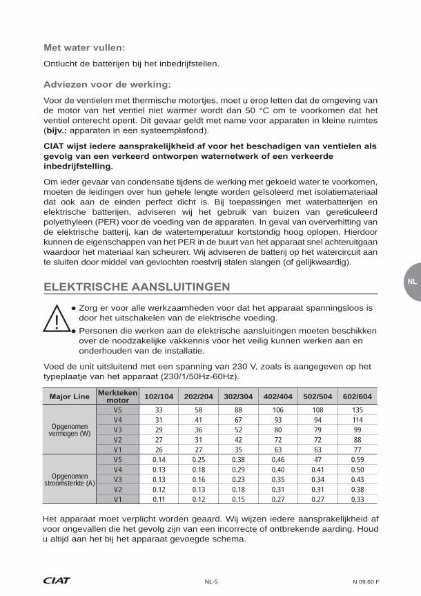
Voed de unit uitsluitend met een spanning van 230 V, zoals is aangegeven op het
!
Merkteken motor 102/104 202/204 302/304 402/404 502/504 602/604
Opgenomen vermogen (W)
V5 33 58 88 106 108 135V4 31 41 67 93 94 114V3 29 36 52 80 79 99V2 27 31 42 72 72 88V1 26 27 35 63 63 77
Opgenomen stroomsterkte (A)
V5 0.14 0.25 0.38 0.46 47 0.59V4 0.13 0.18 0.29 0.40 0.41 0.50V3 0.13 0.16 0.23 0.35 0.34 0.43V2 0.12 0.13 0.18 0.31 0.31 0.38V1 0.11 0.12 0.15 0.27 0.27 0.33
Het apparaat moet verplicht worden geaard. Wij wijzen iedere aansprakelijkheid af voor ongevallen die het gevolg zijn van een incorrecte of ontbrekende aarding. Houd u altijd aan het bij het apparaat gevoegde schema.
N 09.60 F NL-6
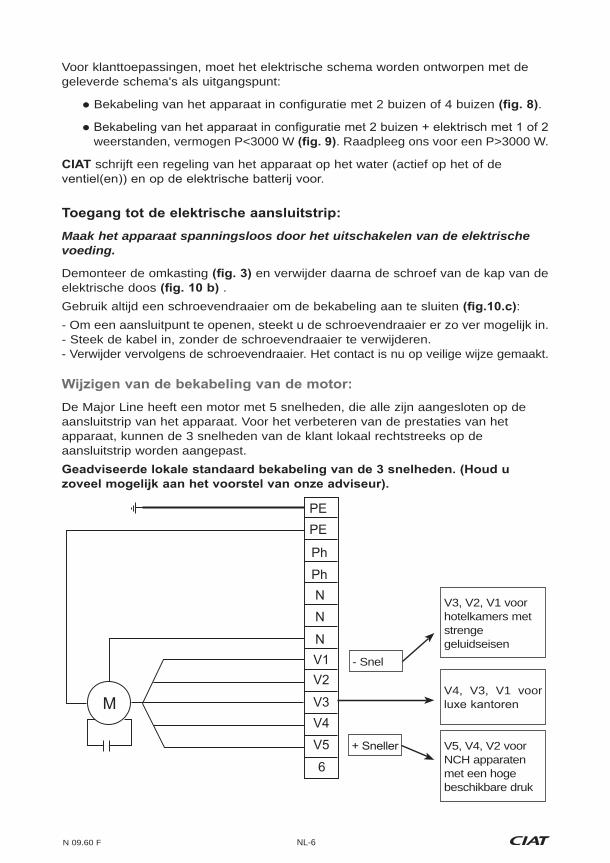
V3, V2, V1 voor hotelkamers met strenge geluidseisen
V4, V3, V1 voor
V5, V4, V2 voor NCH apparaten met een hoge beschikbare druk
PEPE
Ph
NN
NV1V2
V3MV4V5
6
Ph
- Snel
Voor klanttoepassingen, moet het elektrische schema worden ontworpen met de geleverde schema's als uitgangspunt:
Bekabeling van het apparaat in configuratie met 2 buizen of 4 buizen .
weerstanden, vermogen P<3000 W . Raadpleeg ons voor een P>3000 W.
schrijft een regeling van het apparaat op het water (actief op het of de
Maak het apparaat spanningsloos door het uitschakelen van de elektrische voeding.
Demonteer de omkasting en verwijder daarna de schroef van de kap van de elektrische doos .Gebruik altijd een schroevendraaier om de bekabeling aan te sluiten :- Om een aansluitpunt te openen, steekt u de schroevendraaier er zo ver mogelijk in.- Steek de kabel in, zonder de schroevendraaier te verwijderen.- Verwijder vervolgens de schroevendraaier. Het contact is nu op veilige wijze gemaakt.
De Major Line heeft een motor met 5 snelheden, die alle zijn aangesloten op de aansluitstrip van het apparaat. Voor het verbeteren van de prestaties van het apparaat, kunnen de 3 snelheden van de klant lokaal rechtstreeks op de aansluitstrip worden aangepast.

NL
NL-7 N 09.60 F
De MAJOR LINE heeft een schuine gladde kunststof bak, met een aansluiting voor de afvoer Ø 22 mm uitwendig, en een dop.
moet daarom de dop verwijderen aan de kant van de wateraansluiting die u kiest.
de dop aan de andere kant te plaatsen.
De aansluiting is mogelijk aan de linker- of de rechterkant van het apparaat.Elk apparaat kan een eigen afvoerleiding hebben, of deze kunnen worden aangesloten op een verzamelafvoerleiding. Gebruik een transparante afvoerslang en/of buis met een helling van minimaal 1 cm/m, met een constant hoogteverschil over de gehele lengte. Zorg voor een sifon van ten minste 5 cm om stank te voorkomen.
moet verplicht worden bekrachtigd door de ventilator. Met ieder opzettelijk of per ongeluk uitschakelen van de ventilatormotor moet verplicht de voeding worden onderbroken van de elektrische weerstanden en een naventilatie worden toegepast.
worden alleen snelheden voor lage temperatuur geadviseerd om een goede werking van onze beveiligingen te garanderen.
De beveiliging tegen per ongeluk te heet worden van apparaten met
die zijn geplaatst aan de kant van de elektrische doos. Het eventueel resetten van de thermostaten mag pas gebeuren na het verhelpen van de oorzaak van het te warm worden waardoor zij in werking waren gekomen:
> Elektrische voeding zonder ventilatie.
> Regeling die de batterij en de ventilator tegelijk uitschakelt. Sluit nooit meerdere motoren van ventilatorconvectoren parallel aan op
dezelfde thermostaat.
De Comfortunits van CIAT moeten worden aangesloten volgens de internationale
De lekstroom van al onze Comfortunits voldoet aan de eisen van de norm CEI
!
N 09.60 F NL-8
2 schroeven
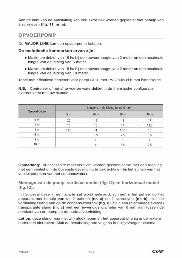
De kan een opvoerpomp hebben.
lengte van de leiding van 5 meter.
lengte van de leiding van 10 meter.
Tabel met effectieve debieten voor pomp SI 10 met PVC-buis Ø 6 mm binnenzijde
Controleer of het af te voeren waterdebiet in de thermische configuratie overeenkomt met uw situatie.
OpvoerhoogteLengte van de leiding (ø int. 6 mm)
5 m 10 m 20 m 30 m
0 m 20 19 18 172 m 16 15 14 13.54 m 11.5 11 10.5 106 m 8.5 7.5 6.58 m 6 5 410 m 4 3.5 2.5
Dit accessoire moet verplicht worden gecombineerd met een regeling met een ventiel om de bovenste beveiliging te bekrachtigen bij het sluiten van het
In het geval deze in een aparte set wordt geleverd, schroeft u het geheel op het apparaat met behulp van de 2 pennen en 2 schroeven , sluit de verbindingsslang aan op de condenswaterbak transparante slang met een inwendige diameter van 6 mm aan tussen de perskant van de pomp en de oude afvoerleiding.
onderdeel niet raken. Sluit de bekabeling aan volgens het bijgevoegde schema.
NL
NL-9 N 09.60 F
Periodiek onderhoud is voorzien tussen het winter- en het zomerseizoen, met name
condenswaterpomp, enz.
omlaag uit de rails.
Kantel de rails door het omhoog te trekken.
Draai de 2 kwartslagschroeven uit zijn houder.
de wisselbatterij dichtslibt. Wij adviseren het bij elke seizoenswisseling te vervangen.
een stofzuiger, in de omgekeerde richting van de luchtstroom. Controleer regelmatig
interval is variabel en afhankelijk van de aard van de ruimtes en de werkomstandigheden van de installatie.
!
!
N 09.60 F NL-10
ONDERHOUD VENTILATORMOTORUNIT
spanningsloos is gemaakt.
Verwijder het luchtfilter .
Verwijder het voorpaneel van de ventilatormotorunit .
door het losmaken van de 2 nokjes met een en de 2 assemblageklemmetjes .
Draai de bevestigingsschroef van de motor los.
Haal de motor/turbine-unit uit het apparaat
Ga bij de montage te werk in omgekeerde volgorde.
indien nodig met een stofzuiger zonder ze te beschadigen. De elektromotor vraagt geen speciaal onderhoud.
De condenswaterbak moet schoon blijven. De plastic bak en de doppen kunnen worden gereinigd met niet-schurende schoonmaakmiddelen op waterbasis.
Verwijder de bak om hem schoon te maken door de 2 schroeven aan de zijkanten en de 2 schroeven aan de voorkant van de bak los te draaien.
De reinheid van de batterij is een belangrijke factor voor het rendement van het apparaat. Reinig de batterij indien nodig met een stofzuiger.
Als het nodig is om de batterij te demonteren in geval van lekkage:
Maak de batterij los van de wateraansluitingen en van de condenswaterafvoer.
Demonteer de ventilatormotorunit
Demonteer de condenswaterbak
Draai de schroeven aan de zijkanten van de wisselbatterij los en door deze vrij te maken tussen de steunpoten van het apparaat.
De demontage van de condenswaterbak is mogelijk zonder de wisselbatterij te verwijderen.
NL
NL-11 N 09.60 F
Neem de buitenkant van het apparaat af met een in een beetje zeepsop gedrenkte spons en wrijf hem glanzend schoon met een zachte droge doek. Gebruik niet-schurende schoonmaakmiddelen op waterbasis.
a - Achterpaneelb - Filterc - Elektrische batterij met 1 of 2 weerstanden
e - Chassissteunpoot rechtsf - Chassissteunpoot links
i - Turbine
k - Bovenste halfrondl - Onderste halfrondm - Voorpaneel van gegalvaniseerd staal
o - Uitblaasroosterp - Afdekkap van bedieningseenheidq - Flens linksr - Flens rechtss - Voorpaneel omkastingt - Voorpaneel omkasting voor luchtaanzuiging aan voorkantu - Geperforeerd luchtaanzuigroosterv - Langsbalkw - Waterbatterij voor 2 buizen of 4 buizen
Al onze apparaten zijn getest en beproefd bij het verlaten van de fabriek.Zij zijn gegarandeerd tegen fabricagefouten, maar wij zijn niet aansprakelijk voor welke vorm van corrosie dan ook. De garantie van de motoren vervalt door een verkeerde elektrische aansluiting, door een verkeerde bescherming of door gebruik
Onze garantie dekt de motoren in geval van de garantie van onze leverancier.
De installateur mag nooit werkzaamheden aan de motor uitvoeren. In het tegenovergestelde geval vervalt onze eventuele garantie.
producten hebben het CE, keurmerk, waardoor deze apparaten overal in de Europese Unie zijn toegelaten. Dit keurmerk is een garantie voor de veiligheid en de bescherming van personen.
N 09.60 F RU-1

RU
RU-2 N 09.60 F
.
-
N 09.60 F RU-3
.
-
:
!

RU
RU-4 N 09.60 F
A AB
AB A
B
: A > AB

N 09.60 F RU-5
(
102/104 202/204 302/304 402/404 502/504 602/604
V5 33 58 88 106 108 135V4 31 41 67 93 94 114V3 29 36 52 80 79 99V2 27 31 42 72 72 88V1 26 27 35 63 63 77V5 0.14 0.25 0.38 0.46 47 0.59V4 0.13 0.18 0.29 0.40 0.41 0.50V3 0.13 0.16 0.23 0.35 0.34 0.43V2 0.12 0.13 0.18 0.31 0.31 0.38V1 0.11 0.12 0.15 0.27 0.27 0.33
!
RU
RU-6 N 09.60 F
.
CIAT.
.
:
-
PEPE
Ph
NN
NV1V2
V3MV4V5
6
Ph
N 09.60 F RU-7
.
!
RU
RU-8 N 09.60 F
ø
5 m 10 m 20 m 30 m
0 m 20 19 18 172 m 16 15 14 13.54 m 11.5 11 10.5 106 m 8.5 7.5 6.58 m 6 5 410 m 4 3.5 2.5
N 09.60 F RU-9
!
!

RU
RU-10 N 09.60 F
.
.
.
.
N 09.60 F RU-11
a - b - c - d - e - f - g - h - i - j - k - l - m - n - o - p - q - r - s - t - u - v - w -
CE
TR
TR-1 N 09.60 F
pano
CV, CH Kasetli Model
NCV, NCH Kasetsiz Model
1 - Serpantin2 - Fan motor grubu
Ø22mm
7 - Duvara veya tavana sabitleme kilit
N 09.60 F TR-2
verebilir.
konuma getiriniz.
sabitlenmelidir.
TR
TR-3 N 09.60 F
.
:
- 2 borulu 2 yollu vana - 4 borulu 2 yollu vana
- 2 borulu 4 yollu vana - 4 borulu 4 yollu vana
!
N 09.60 F TR-4
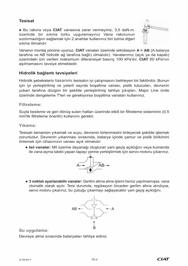
A AB
AB A
B
Bu rakora veya
A > AB (A batarya

TR
TR-5 N 09.60 F
Her tür müdahaleden önce, elektrik beslemesini keserek cihaza
gerilimle besleyiniz.
!
Motor 102/104 202/204 302/304 402/404 502/504 602/604
Çekilen güç (W)
V5 33 58 88 106 108 135V4 31 41 67 93 94 114V3 29 36 52 80 79 99V2 27 31 42 72 72 88V1 26 27 35 63 63 77
(A)
V5 0.14 0.25 0.38 0.46 47 0.59V4 0.13 0.18 0.29 0.40 0.41 0.50V3 0.13 0.16 0.23 0.35 0.34 0.43V2 0.12 0.13 0.18 0.31 0.31 0.38V1 0.11 0.12 0.15 0.27 0.27 0.33
kaynaklanan kazalar durumunda CIAT sorumluluk üstlenmeyecektir. Daima cihazla
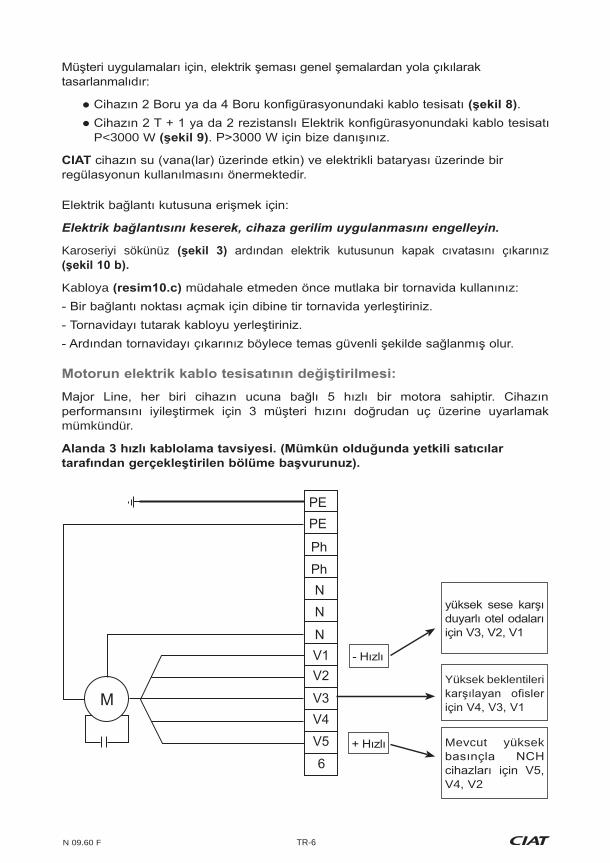
N 09.60 F TR-6
Yüksek beklentileri
Mevcut yüksek
V4, V2
PEPE
Ph
NN
NV1V2
V3MV4V5
6
Ph
.
P<3000 W
Karoseriyi sökünüz
Kabloya
mümkündür.
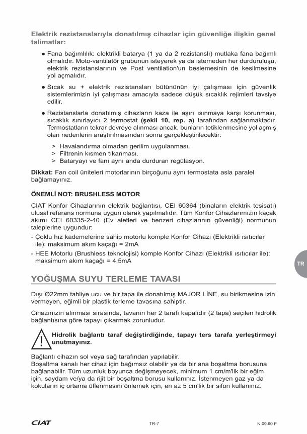
TR
TR-7 N 09.60 F
edilir.
taleplerine uygundur:
!
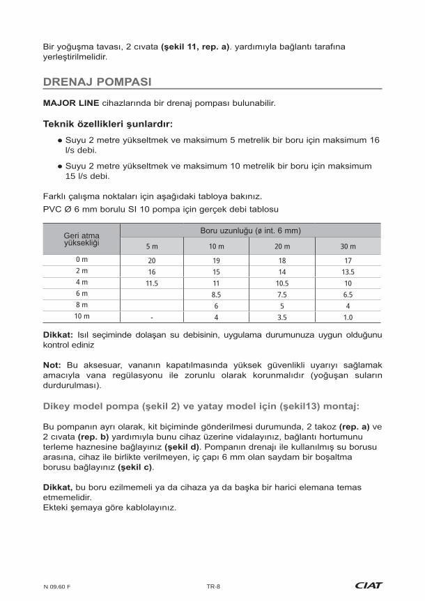
N 09.60 F TR-8
Geri atma ø
5 m 10 m 20 m 30 m
0 m 20 19 18 172 m 16 15 14 13.54 m 11.5 11 10.5 106 m 8.5 7.5 6.58 m 6 5 410 m - 4 3.5 1.0
l/s debi.
15 l/s debi.
kontrol ediniz
ve
.
etmemelidir.

TR
TR-9 N 09.60 F
ve
.
klipsleyiniz.
!
!
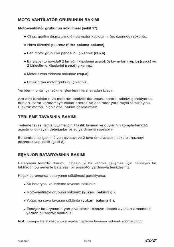
N 09.60 F TR-10
.
.
ve
.
Moto-vantilatör grubunu sökünüz
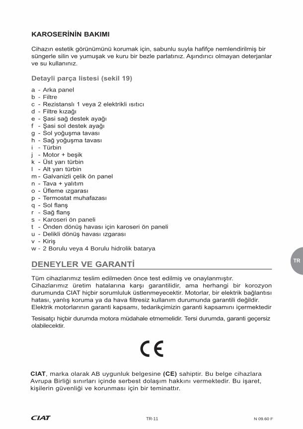
TR
TR-11 N 09.60 F
a - Arka panelb - Filtre
i - Türbin
s - Karoseri ön paneli
w - 2 Borulu veya 4 Borulu hidrolik batarya
olabilecektir.
, marka olarak AB uygunluk belgesine sahiptir. Bu belge cihazlara

N 09.60 F HU-1
A társaság köszöni, hogy Major Line berendezését választotta, reméljük hogy a használat
Mennyiségi hiány esetén az átvevõnek jeleznie kell, hogy pontosan hány csomag érkezett.
Ezeket a megjegyzéseket, a francia kereskedelmi törvény 105. cikkelyének
"feltételesen" és a "feltételesen, kicsomagolás nélkül" megjegyzések érvénytelenek. Az
fenntartásokat pontosan meg kell fogalmazni.
Burkolatos kivitel CV, CH
hozzáférési pontja (szabályozás külön
4 - Homloklap elõlakkozott lemezbõl RAL 9010
1 - Hõcserélõ
2 - Motor-ventilátor egység
szerelõfedele
külsõ hõszigeteléssel11 - Levegõszûrõ
Burkolat nélküli kivitel NCV, NCH
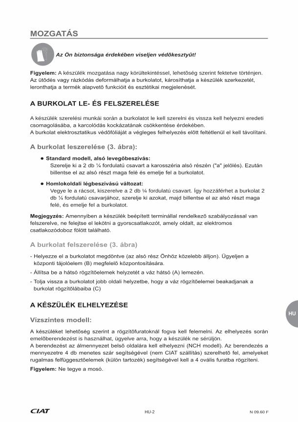
HU
HU-2 N 09.60 F
Az Ön biztonsága érdekében viseljen védõkesztyût!
A készülék mozgatása nagy körültekintéssel, lehetõség szerint fektetve történjen.
A készülék szerelési munkái során a burkolatot le kell szerelni és vissza kell helyezni eredeti
Vegye le a rácsot, kiszerelve a 2 db ¼ fordulatú csavart. Így hozzáférhet a burkolat 2
felé, és emelje fel a burkolatot.
emelõberendezést is használhat, ügyelve arra, hogy a készülék ne sérüljön.
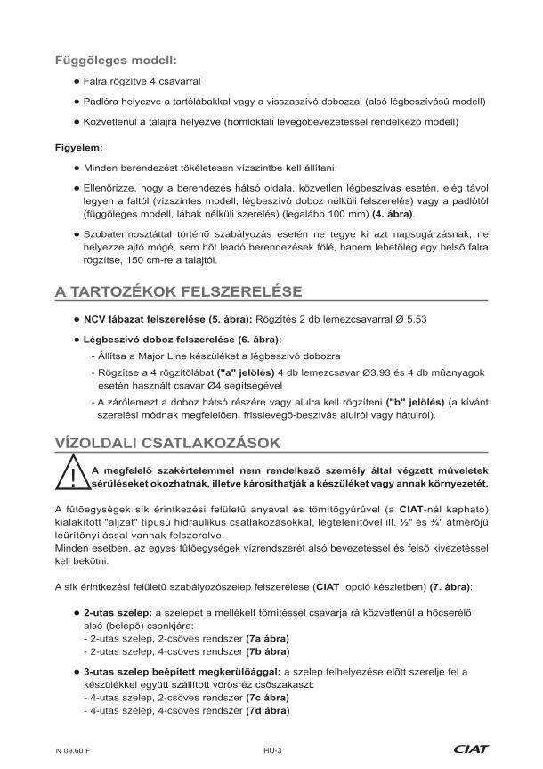
N 09.60 F HU-3
.
Szobatermosztáttal történõ szabályozás esetén ne tegye ki azt napsugárzásnak, ne
4 db lemezcsavar Ø3.93 és 4 db mûanyagok
kell bekötni.
:
- 2-utas szelep, 2-csöves rendszer - 2-utas szelep, 4-csöves rendszer
a szelep felhelyezése elõtt szerelje fel a
- 4-utas szelep, 2-csöves rendszer - 4-utas szelep, 4-csöves rendszer
!
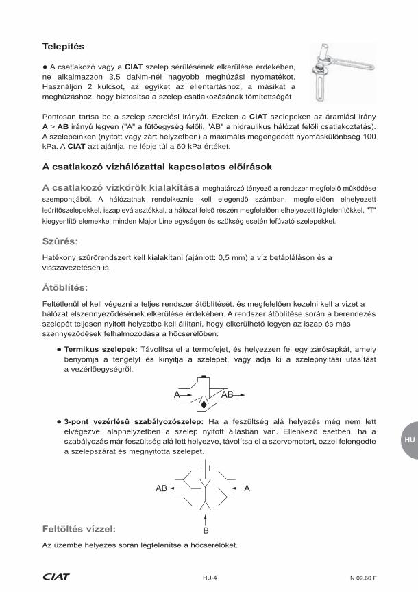
HU
HU-4 N 09.60 F
A AB
AB A
B
szelep sérülésének elkerülése érdekében, ne alkalmazzon 3,5 daNm-nél nagyobb meghúzási nyomatékot. Használjon 2 kulcsot, az egyiket az ellentartáshoz, a másikat a
Pontosan tartsa be a szelep szerelési irányát. Ezeken a szelepeken az áramlási irány A > AB
kPa. A azt ajánlja, ne lépje túl a 60 kPa értéket.
visszavezetésen is.
a vezérlõegységrõl.
Ha a feszültség alá helyezés még nem lett elvégezve, alaphelyzetben a szelep nyitott állásban van. Ellenkezõ esetben, ha a
a szelepszárat és megnyitotta szelepet.
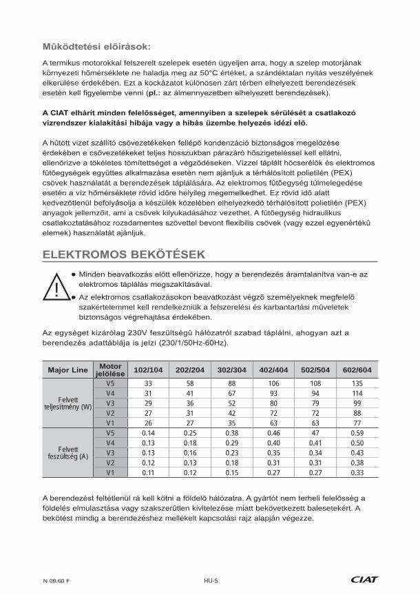
N 09.60 F HU-5
A termikus motorokkal felszerelt szelepek esetén ügyeljen arra, hogy a szelep motorjának környezeti hõmérséklete ne haladja meg az 50°C értéket, a szándéktalan nyitás veszélyének elkerülése érdekében. Ezt a kockázatot különösen zárt térben elhelyezett berendezések
csövek használatát a berendezések táplálására. Az elektromos fûtõegység túlmelegedése
anyagok jellemzõit, ami a csövek kilyukadásához vezethet. A fûtõegység hidraulikus
Az elektromos csatlakozásokon beavatkozást végzõ személyeknek megfelelõ szakértelemmel kell rendelkezniük a felszerelési és karbantartási mûveletek biztonságos végrehajtása érdekében.
!
Motor 102/104 202/204 302/304 402/404 502/504 602/604
Felvett teljesítmény (W)
V5 33 58 88 106 108 135V4 31 41 67 93 94 114V3 29 36 52 80 79 99V2 27 31 42 72 72 88V1 26 27 35 63 63 77
Felvett feszültség (A)
V5 0.14 0.25 0.38 0.46 47 0.59V4 0.13 0.18 0.29 0.40 0.41 0.50V3 0.13 0.16 0.23 0.35 0.34 0.43V2 0.12 0.13 0.18 0.31 0.31 0.38V1 0.11 0.12 0.15 0.27 0.27 0.33
földelés elmulasztása vagy szakszerûtlen kivitelezése miatt bekövetkezett balesetekért. A bekötést mindig a berendezéshez mellékelt kapcsolási rajz alapján végezze.
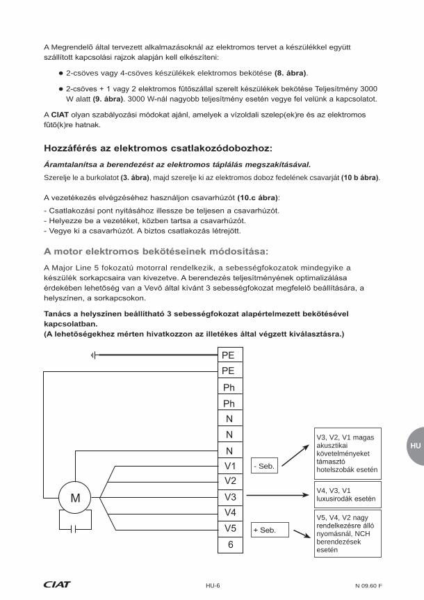
HU
HU-6 N 09.60 F
V3, V2, V1 magas akusztikai követelményeket
hotelszobák esetén
V4, V3, V1
V5, V4, V2 nagy
nyomásnál, NCH berendezések esetén
PEPE
Ph
NN
NV1V2
V3MV4V5
6
Ph
- Seb.
A Megrendelõ által tervezett alkalmazásoknál az elektromos tervet a készülékkel együtt
2-csöves vagy 4-csöves készülékek elektromos bekötése .
W alatt
A
Áramtalanítsa a berendezést az elektromos táplálás megszakításával.
Szerelje le a burkolatot , majd szerelje ki az elektromos doboz fedelének csavarját .
:
A Major Line 5 fokozatú motorral rendelkezik, a sebességfokozatok mindegyike a
kapcsolatban.
N 09.60 F HU-7
feltétlenül reteszelni kell a ventilátor üzeméhez. A motor-ventilátor egység szándékos
mûködhessenek.
A fûtõellenállásokkal felszerelt berendezések véletlenszerû túlmelegedés elleni , amelyek
> Feszültség alá helyezés a ventilátor mûködése nélkül. > A szûrõ részleges eltömõdése.
termosztátra.
A CIAT komfort egységek elektromos bekötését az IEC 60364 (Épületek villamos
kellemetlen szagok és a gázok visszaáramlásának megelõzése érdekében szereljen fel egy legalább 5 cm-es szifont.
!

HU
HU-8 N 09.60 F
A
hosszúságú csõvezeték esetén.
hosszúságú csõvezeték esetén.
A különbözõ üzemelési pontokkal kapcsolatban lásd az alábbi táblázatot.
esetén.
Leengedési magasság
Csõvezeték hossza (ø int. 6 mm)
5 m 10 m 20 m 30 m0 m 20 19 18 172 m 16 15 14 13.54 m 11.5 11 10.5 106 m 8.5 7.5 6.58 m 6 5 410 m 4 3.5 2.5
mennyisége megfelel-e az adott alkalmazási igényeknek.
és 2 csavar . Kössön egy 6 mm belsõ átmérõjû
Elektromos bekötés a mellékelt kapcsolási rajz szerint.

N 09.60 F HU-9
A fûtési és hûtési idõszakok között rendszeres karbantartást kell beütemezni, különös
és csúsztassa a szûrõt
A szûrõ kiemeléséhez hajtsa ki a vezetõelemeket felfelé húzva húzva.
húzva.
érdekében.
Csavarja ki a 2 db ¼ fordulatú csavart , hajtsa ki a rácsot és emelje ki a szûrõt a helyérõl.
A szûrõ jelenléte nélkülözhetetlen a berendezés megfelelõ mûködése érdekében, ellenkezõ esetben fennáll a hõcserélõ fûtõegység eltömõdésének veszélye. Javasoljuk, hogy a légszûrõt
hely jellegétõl és a beszerelés feltételeitõl függõen nagyon különbözõ lehet.
!
!

HU
HU-10 N 09.60 F
Kösse le a motor vezetékeit
Vegye ki a levegõszûrõt .
.
és a 2 szerelõkapcsot .
.
különleges karbantartást.
.
Ha szivárgás miatt ki kell szerelni a hõcserélõt:
között.
elvégezhetõ.
N 09.60 F HU-11
A termékek jogosultak a CE megfelelõségi jelzés viselésére. E termékek szabadon
biztonságos használatát és a személyi biztonságot.
A berendezés esztétikus megjelenésének megõrzéséhez törölje át enyhén szappanos nedves
a - b - Szuroc - 1 vagy 2 ellenállással felszerelt elektromos futoegységd - A szuro vezetoeleme e - f - g - h - i - j - k - Felso csigaház-féll - m - n - o - p - Terminál burkolataq - Bal oldali burkolatr - Jobb oldali burkolats - Burkolat homloklapjat - u - v - w - 2-csöves vagy 4-csöves hidraulikus futoegység
védelemre vagy a levegõszûrõ nélküli használatra.
A felszerelést végzõ semmilyen beavatkozást sem végezhet a motoron. Ellenkezõ esetben az esetleges garancia érvényét veszti.
PL
PL-1 N 09.60 F
Firma
instrukcji.
adresata jest sprawdzenie stanu towaru.
paczek.
1 - Kratka nadmuchu
PC
lakierowanej RAL 9010
5 - Kratka wywiewu z blachy perforowanej do wersji z przednim wywiewem powietrza.
Model bez obudowy NCV, NCH
1 - Bateria wymienna
5 - Odprowadzenie skroplin Ø 22mm
6 - Dodatkowy zbiornik na skropliny
10 - Korek spustowy baterii
11 - Filtr powietrza

N 09.60 F PL-2
oryginalnym opakowaniu, w celu zabezpieczenia przed ewentualnym zarysowaniem.
-

PL
PL-3 N 09.60 F
.
!
:
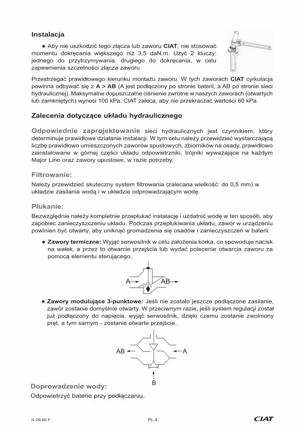
N 09.60 F PL-4
A AB
AB A
B
Instalacja
cyrkulacja A > AB
Major Line oraz zawory upustowe, w razie potrzeby.
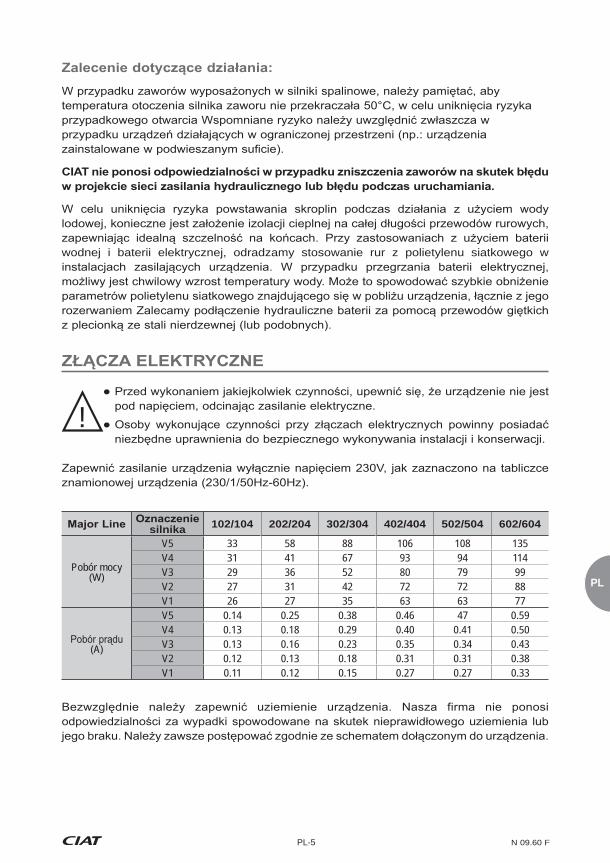
PL
PL-5 N 09.60 F
silnika 102/104 202/204 302/304 402/404 502/504 602/604
Pobór mocy (W)
V5 33 58 88 106 108 135V4 31 41 67 93 94 114V3 29 36 52 80 79 99V2 27 31 42 72 72 88V1 26 27 35 63 63 77
(A)
V5 0.14 0.25 0.38 0.46 47 0.59V4 0.13 0.18 0.29 0.40 0.41 0.50V3 0.13 0.16 0.23 0.35 0.34 0.43V2 0.12 0.13 0.18 0.31 0.31 0.38V1 0.11 0.12 0.15 0.27 0.27 0.33
wodnej i baterii elektrycznej, odradzamy stosowanie rur z polietylenu siatkowego w
!

N 09.60 F PL-6
V3, V2, V1 do pokoi hotelowych
wymaganiach akustycznych
V4, V3, V1 do biur o wysokim standardzie
V5, V4, V2 do
PEPE
Ph
NN
NV1V2
V3MV4V5
6
Ph
- Szybko
oparciu o dostarczone schematy:
.
mocy P<3000 W
Aby urz¹dzenie nie znajdowa³o siê pod napiêciem, odci¹æ zasilanie elektryczne.
elektrycznego .
okablowaniem :
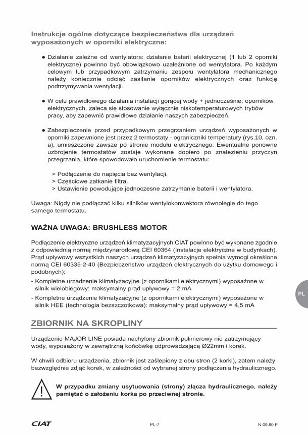
PL
PL-7 N 09.60 F
podtrzymywania wentylacji.
oporniki zapewnione jest przez 2 termostaty - ograniczniki temperatury (rys.10, ozn.
samego termostatu.
!
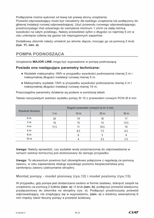
N 09.60 F PL-8
ramach selekcji termicznej jest dostosowany do danego przypadku
.
5 m 10 m 20 m 30 m
0 m 20 19 18 172 m 16 15 14 13.54 m 11.5 11 10.5 106 m 8.5 7.5 6.58 m 6 5 410 m 4 3.5 2.5

PL
PL-9 N 09.60 F
z gniazda.
!
!
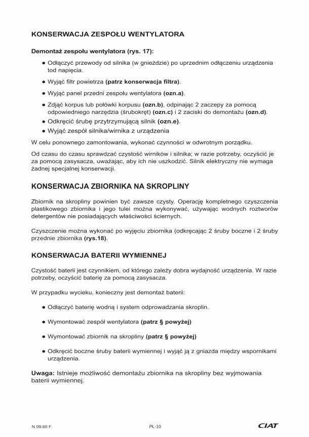
N 09.60 F PL-10
.
.
.
.
przednie zbiornika .
baterii wymiennej.
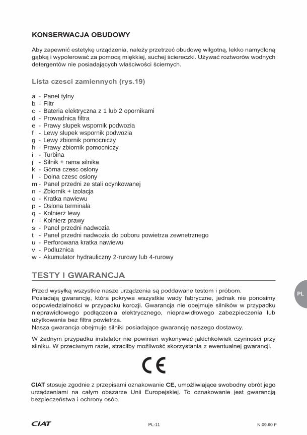
PL
PL-11 N 09.60 F
a - Panel tylnyb - Filtrc - Bateria elektryczna z 1 lub 2 opornikamid - Prowadnica filtrae - Prawy slupek wspornik podwoziaf - Lewy slupek wspornik podwoziag - Lewy zbiornik pomocniczyh - Prawy zbiornik pomocniczy i - Turbinaj - k - l - Dolna czesc oslonym - Panel przedni ze stali ocynkowanejn - o - Kratka nawiewup - Oslona terminalaq - Kolnierz lewyr - Kolnierz prawys - Panel przedni nadwoziat - Panel przedni nadwozia do poboru powietrza zewnetrznegou - Perforowana kratka nawiewuv - Podluznicaw - Akumulator hydrauliczny 2-rurowy lub 4-rurowy
stosuje zgodnie z przepisami oznakowanie CE


Siège socialAvenue Jean Falconnier B.P. 14
01350 Culoz - France Tel. : +33 (0)4 79 42 42 42Fax : +33 (0)4 79 42 42 [email protected] - www.ciat.com
Compagnie Industrielled’Applications Thermiques
S.A. au capital de 26 728 480 €R.C.S. Bourg-en-Bresse B 545.620.114
(0,15
Document non contractuel. Dans le souci constant,d’améliorer son matériel, CIAT se réserve
le droit de procéder sans préavis à toutes modifications techniques.
Non-contractual document. With the thought of material improvement always in mind, CIAT reserves the right, without notice
to proceed with any technical modification.
Dieses Dokument ist keine Vertragsunterlage.
Änderungen ohne vorherige Ankündigung vorzunehmen.
Documento no contractual. En la preocupaciòn constantede mejorar su material, CIAT se reserva el derecho de proceder,
sin previo aviso, a cualquier modificaciòn technica.
Documento non contrattuale. Nella preoccupazione costante di migliorare il suo materiale, CIAT si riserva il diritto di procederesenza preavviso a tutte le modificazioni tecniche necessarie.
Niet contractueel document. In het vooruitzicht het materiaal steeds te verbeteren, behoud CIAT zich het recht voor om zonder
verwittiging technische wijzigingen aan te brengen
Nem szerzõdéses dokumentum. A berendezések folyamatos fejlesztését szem elõtt tartva, a CIAT fenntartja a jogot minden