network coding in transcad - الصفحات الشخصية...
TRANSCRIPT
Network Coding in TransCADMurtaza [email protected]: 416.979.5000, ext. 2480
Creating and Using Networks
• Goal: understand what a network is and how to:– Create a network
– Solve a shortest path problem
– Enable and disable links
– Work with one-way streets
Basics: Network
• Definition: A special TransCAD data structure that is created from a reference line layer and is used to analyze the way people and commodities flow from one location to another
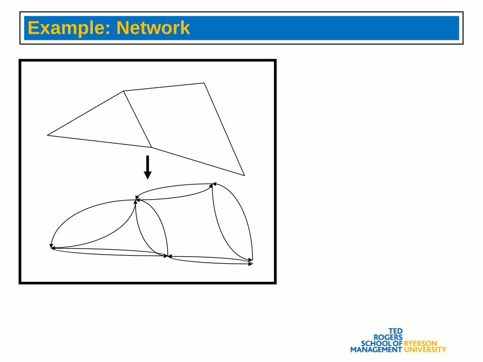
Example: Network
Basics: Nodes and Links
• Nodes are locations where flows start, end, or branch
• Links are conduits that carry directional flow from node to node
• Every node and link in a network has an ID• TransCAD usually creates two network links for
every line feature• Line features can be designated as one-way
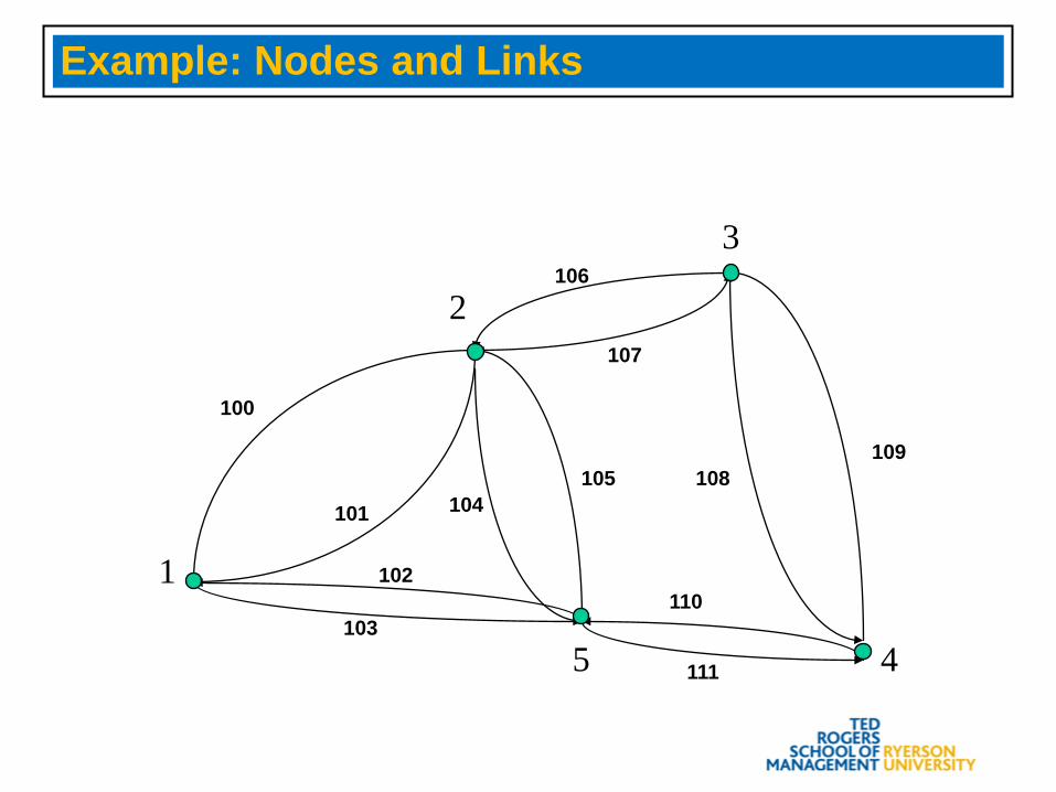
Example: Nodes and Links
1
2
3
45
100
101
102
103
104105
106
107
108109
110
111
Basics: Network Attributes
• Network nodes and links contain costs and other attributes
• The attributes are taken from the line and endpoint layers
• TransCAD procedures require at least one attribute to be present in a network
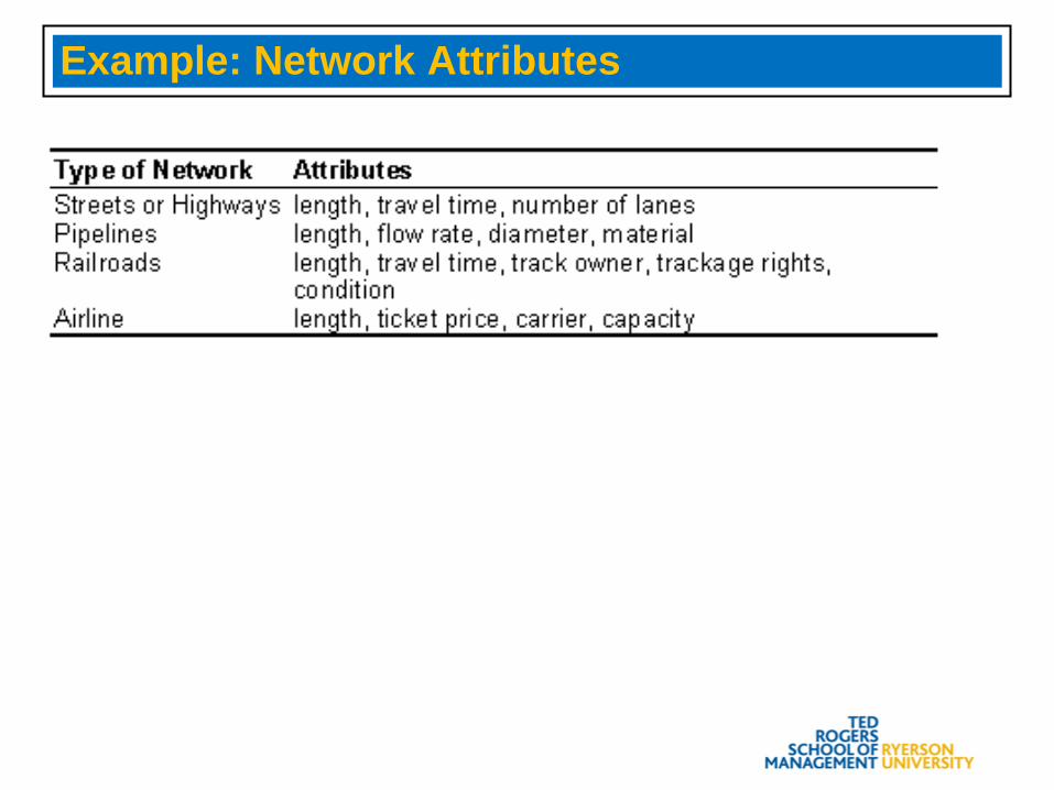
Example: Network Attributes
Quick Start: Getting Ready to Create a Network
• Choose File-Close All, then choose File-Open or click on the toolbar.
• Open the geographic file BOSTON.CDF in the TCW\TUTORIAL directory. TransCAD displays downtown Boston.
• If Network/Paths is not on the menu, choose Procedures-Network/Paths.
Creating a Network
• Choose Network/Paths-Create. TransCAD displays the Create Network dialog box.
• All the settings are correct. Click OK.• Enter MYNET as the network file name and click
OK. TransCAD creates a network from the Streets line layer.
Changing a Network
• Choose Network/Paths-Settings. TransCAD displays the Network Settings dialog box.
• Click Network and choose BOSTON.NET as the network. TransCAD changes the current network in memory to BOSTON.NET.
• Click Info to display information about the network. Click Close when you are done.
In Depth: Options When Creating a Network
• You have several options when you create a network. You can:– Create a network from a selection of line features– Add node and link attributes to the network– Include turn information– Ignore link direction
Creating a Network
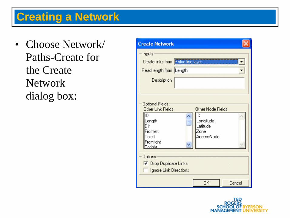
• Choose Network/Paths-Create for the Create Network dialog box:
Basics: Shortest Path
• Definition: The path taken from one location to another that minimizes the total value of a network cost attribute
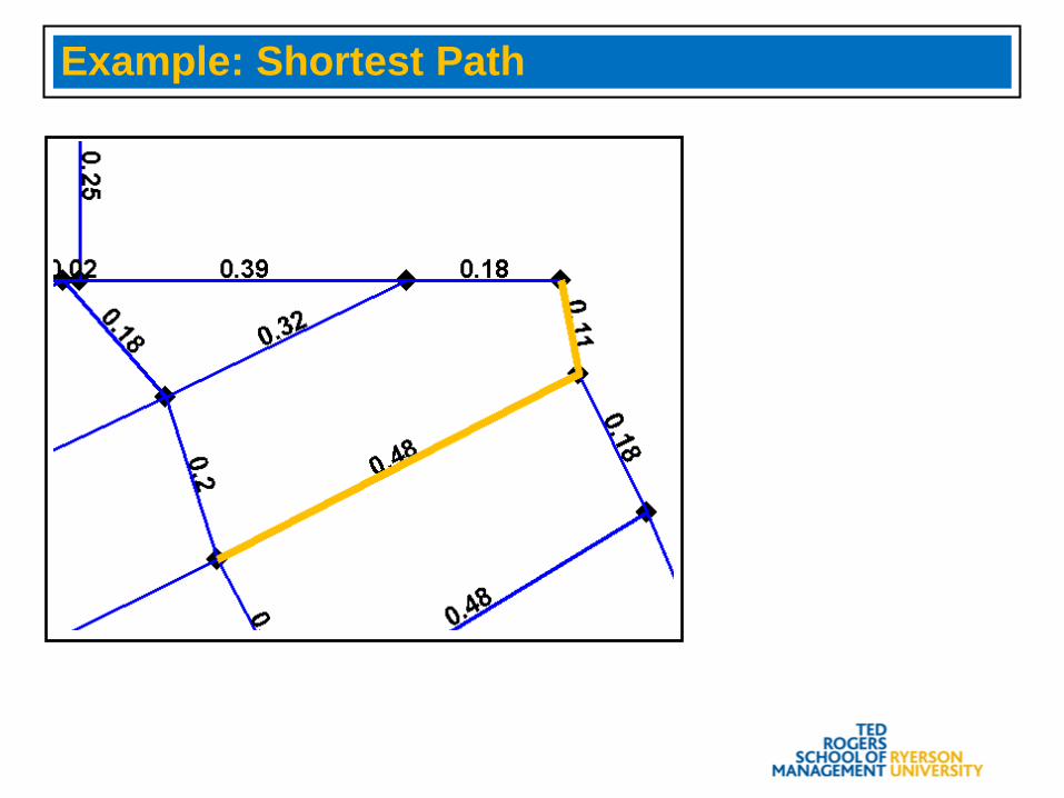
Example: Shortest Path

Getting Ready to Display a Shortest Path
• Choose File-Close All, then choose File-Open or click on the toolbar.
• Open the geographic file SAN_FRAN.CDF. TransCAD displays the streets of San Francisco.
• Click and open the network file SAN_FRAN.NET in TCW\TUTORIAL. TransCAD displays the Network dialog box. Click OK.
Displaying a Shortest Path
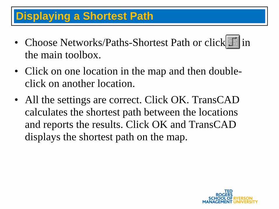
• Choose Networks/Paths-Shortest Path or click in the main toolbox.
• Click on one location in the map and then double-click on another location.
• All the settings are correct. Click OK. TransCAD calculates the shortest path between the locations and reports the results. Click OK and TransCAD displays the shortest path on the map.
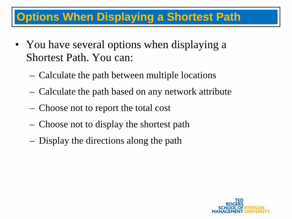
Options When Displaying a Shortest Path
• You have several options when displaying a Shortest Path. You can:– Calculate the path between multiple locations
– Calculate the path based on any network attribute
– Choose not to report the total cost
– Choose not to display the shortest path
– Display the directions along the path
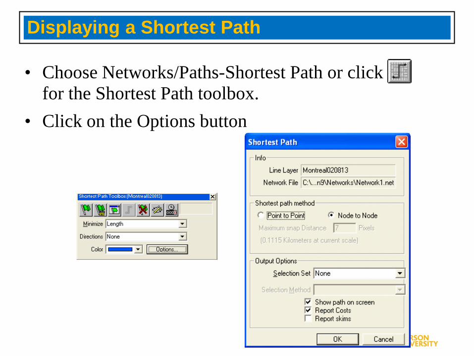
Displaying a Shortest Path
• Choose Networks/Paths-Shortest Path or click for the Shortest Path toolbox.
• Click on the Options button
Basics: Skimming
• Definition: The process of computing the total value of multiple network attributes along a shortest path. One attribute is used to calculate the shortest path and other attributes are “skimmed” from that shortest path
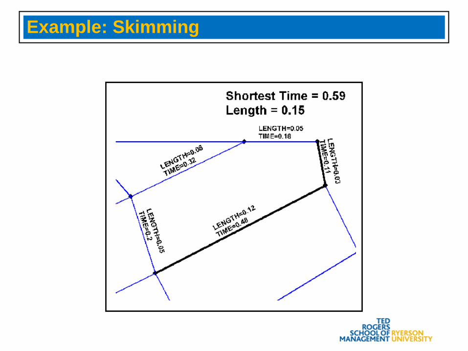
Example: Skimming
Getting Ready to Skim a Shortest Path
• Choose File-Close All, then choose File-Open or click on the toolbar.
• Open the geographic file BOSTON.CDF. TransCAD displays the streets of Boston.
• Click and open the network file BOSTON.NET in TCW\TUTORIAL. TransCAD displays the Network dialog box. Click OK.
Displaying a Shortest Path
• Choose Networks/Paths-Shortest Path or click in the main toolbox.
• Click on one location in the map and then double-click on another location.
• Choose the [TIME(min)] field from the Minimize drop-down list.
• Click Skims to display the Network Skim Settings dialog box.
Skimming a Network Field
• For the LENGTH field, choose All Links in the Skim Type drop-down list and click OK.
• Check the Report Skims box and click OK. TransCAD calculates and displays the minimum time between two locations.
• Click OK again. TransCAD reports the total length on the shortest path.
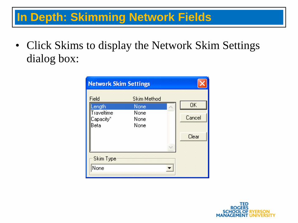
In Depth: Skimming Network Fields
• Click Skims to display the Network Skim Settings dialog box:
Basics: Updating Networks
• Once a network is created, the links and attributes in the network file cannot be changed, but you can update portions of the network such as:– Enable or disable selected links in the network file– Change link attributes from the line layer dataview and
then update these attributes in the network
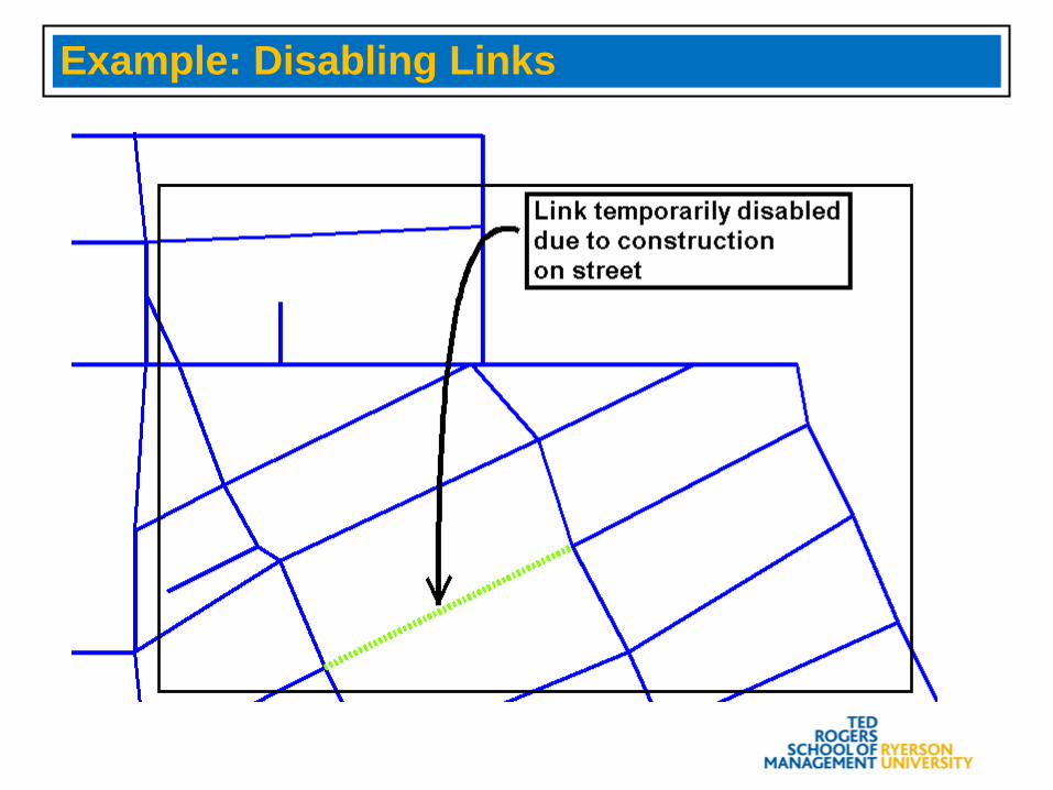
Example: Disabling Links
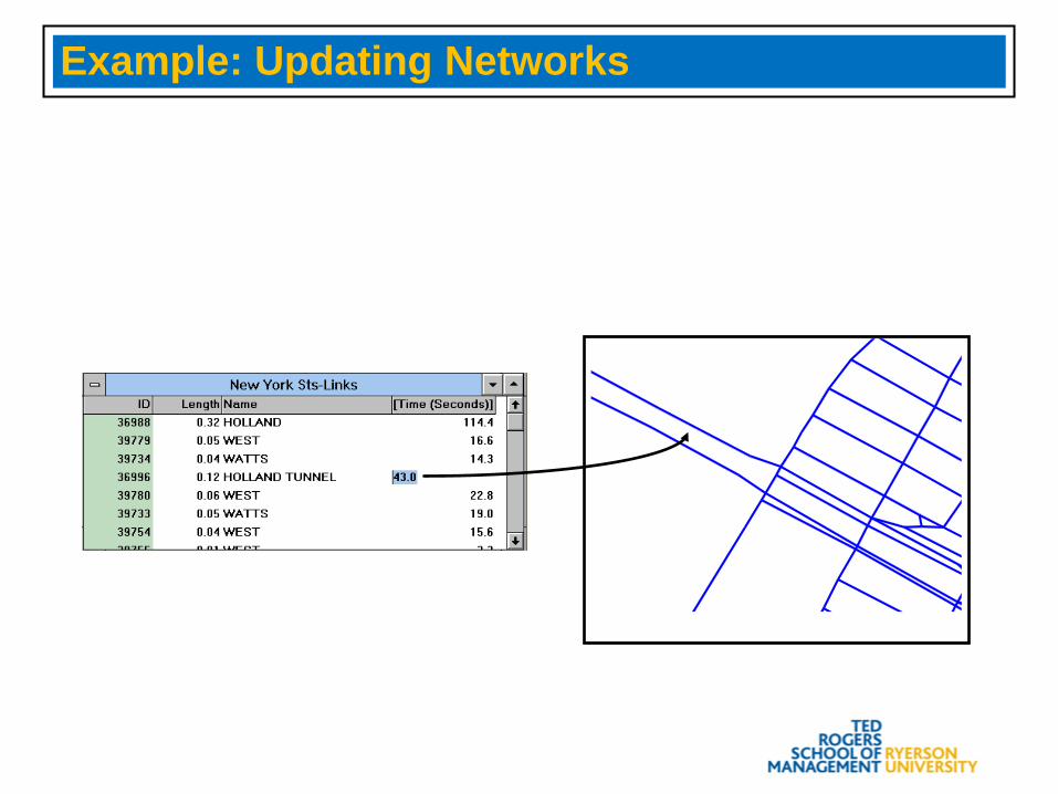
Example: Updating Networks
Getting Ready To Disable a Link #1
• Choose File-Close All, then choose File-Open or click on the toolbar.
• Open the geographic file MAN_STR.DBD in the TCW\TUTORIAL directory. TransCAD displays streets in Manhattan.
• Zoom in and select street segments within a circle of about a quarter mile radius.
Getting Ready To Disable a Link #2
• Choose Networks/Paths-Create.• Choose Selection from the Create links from drop-
down list and click OK.• Enter MYMANHAT as the network file name and
click OK. TransCAD creates a network from the selection.
Displaying a Shortest Path
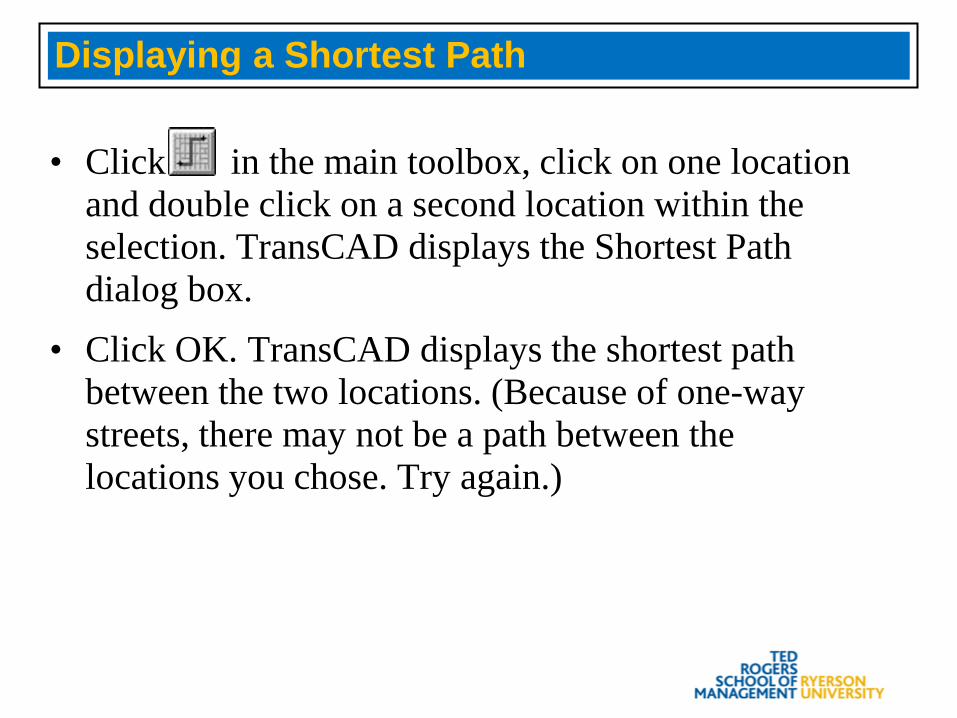
• Click in the main toolbox, click on one location and double click on a second location within the selection. TransCAD displays the Shortest Path dialog box.
• Click OK. TransCAD displays the shortest path between the two locations. (Because of one-way streets, there may not be a path between the locations you chose. Try again.)
Disabling a Link
• Select a street segment that is on the path and then choose Networks/Paths-Settings.
• Click Update to display the Update Network dialog box.
• Choose Disable Links from the Option drop-down list and Selection from the Using drop-down list.
• Click OK. TransCAD disables the link.
Displaying a Shortest Path Again
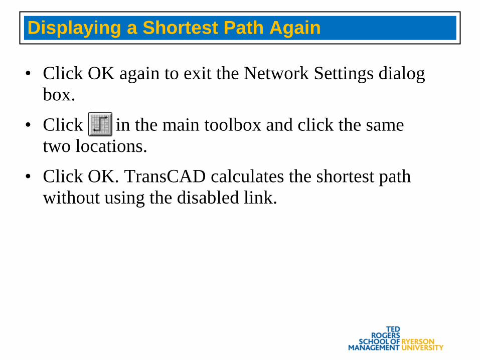
• Click OK again to exit the Network Settings dialog box.
• Click in the main toolbox and click the same two locations.
• Click OK. TransCAD calculates the shortest path without using the disabled link.
In Depth: Updating Networks
• There are several options when updating a network. You can:– Enable and disable links based on an expression
– Update costs on all links for all network fields, or only update costs for selected fields
Updating Networks
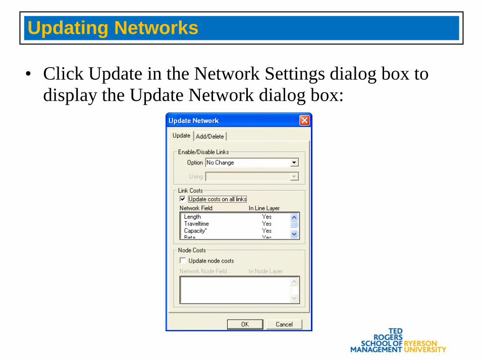
• Click Update in the Network Settings dialog box to display the Update Network dialog box:
Basics: One-Way Streets
• When TransCAD creates a network, most of the time a line feature is considered bi-directional and TransCAD converts the line into two one-way links
• A line feature can be designated as uni-directional if you change the value in its DIR or DIRECTION field. The network must be recreated to reflect the change
• TransCAD can show direction of flow
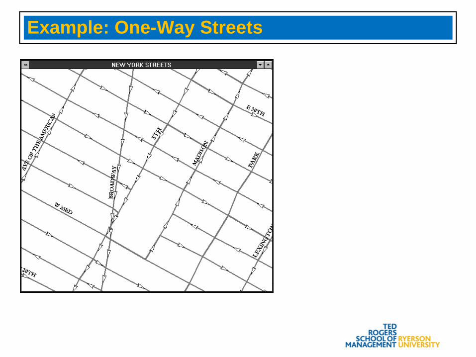
Example: One-Way Streets
Basics: Direction of Flow and Topology
• Direction of Flow: The direction in which flow is allowed to travel
• Topology: The order in which the endpoints of a line feature are connected
Changing the Value of Direction
• The direction of a line feature is stored in a field called DIR or DIRECTION that can have the following values:– 0: Travel is allowed for both directions– 1: Travel is one-way in the same direction that the
endpoints are connected (with topology)– -1: Travel is one-way in the direction opposite from the
way the endpoints are connected (against topology)
Quick Start: Getting Ready To Show Directions
• Choose File-Close All, then choose File-Open or click on the toolbar.
• Open the geographic file MAN_STR.DBD. TransCAD displays streets in Manhattan.
• Zoom in to display a few streets.• Click on the toolbar.
Showing Directions
• Choose Topology from the Arrowheads radio buttons, and click OK. TransCAD shows the direction of the lines based on the order in which the endpoints are connected.
• Click on the toolbar again.• Choose Direction of Flow from the Arrowheads
radio buttons, and click OK. TransCAD shows all one-way streets.
Changing Directions
• Click in the main toolbox.• Click on a bi-directional line (a line with no
arrows).• In the Info dataview, change the value of the DIR
field to 1.• Choose Windows-Redraw. The line is now one-
way.
Marking One-Way Streets
• Use a selection tool and select several line features running generally east-west.
• Choose Networks/Paths-Link Directions to display the Link Direction dialog box.
• Choose Selection from the Mark drop-down list, choose One Way Eastbound for the direction, and click OK. TransCAD changes the directions of all of the selected lines.