new application using super-long-range piv system for non
TRANSCRIPT
13th Int Symp on Applications of Laser Techniques to Fluid Mechanics Lisbon, Portugal, 26-29 June, 2006
#1337
1
New Application using Super-Long-Range PIV System for Non-Contacting Measurement of Flow-Induced Vibration
Hideaki Tezuka1, Michitsugu Mori1,Koichi Hishida2
1)R & D Center, Tokyo Electric Power Co., Inc.
4-1 Egasaki, Tsurumi-ward, Yokohama-city, 230-8510 Japan
TEL:++81-45-613-6701/FAX:7899/E-MAIL:[email protected]
2)Department of System Design Engineering, Keio University
Hiyoshi 3-14-1, Kohoku-ward, Yokohama-city, 223-8522 Japan
Abstract Expanded technologies on Long-Range PIV by using the CCD camera with the long-focus optical system enabled us to measure the velocity field hardly accessible as the top of the soaring chimney at fossil-fired power plants. Field application development for such sophisticated technologies as Super-Long-Range PIV was utilized for managing operation and considering effects on the environment in the power plants. It has the possibility effective in grasping the surrounding environment as large-scale phenomena for a power plant, and furthermore grasping the influence of the natural disaster on the environment such as a volcanic eruption. In present investigation, we have extended the Super-Long-Range PIV technology and developed its new application for non-contacting measurement of Flow-Induced Vibration (FIV). This system can measure a wide velocity field with a long distance. Using this system, a velocity field in the location difficult to access and therefore so far difficult to measure is measurable with a long distance without close access to the measurement target. In this study, we used the system (Super-Long Range PIV System) which was the combination with the already-developed optical system suitable for long range measurement, and applied it to the non-contacting measurement of flow-induced vibration on structures (rigid bodies). The troubles are caused by FIV have been significant issues for power plant facilities. New application using Super-Long-Range PIV system for non-contacting measurement of Flow-Induced Vibration (FIV) has been developed, and vibration originated from FIV caused by internal flows and external flows was measured.
1. Introduction
We have extended the conventional PIV technology(1) and developed a system using long focal length optics with the use of a telescope instead of conventional imaging lenses(2). This system can measure a wide velocity field from a long distance. Using this system, a velocity field in the location difficult to access and therefore so far difficult to measure is measurable from a long distance without close access to the measurement target. This system is suitable for measuring targets in the location not easily accessible such as, for example, boiler stacks installed high in a power station, wind power generation facilities, and volcanic smoke.
In this study, we used the system (Super-Long Range PIV)(2) which was the combination with the already-developed optical system suitable for long range measurement, and applied it to the measurement of vibration of structures (rigid bodies). For electric power facilities, facility trouble caused by flow-related vibration is a significant issue. While it is important to identify the cause of
13th Int Symp on Applications of Laser Techniques to Fluid Mechanics Lisbon, Portugal, 26-29 June, 2006
#1337
2
vibration, investigations of the impact caused by the structure itself (i.e. vibration) are important as well for the maintenance of facilities. It used to cost a large amount to measure targets located high or difficult to access. The PIV method enables us to obtain not only the displacement but also the information of the velocity and acceleration in any area of the photographed image. It is also possible to utilize widely studied high precision methods and a number of highly functional PIV devices available such as high speed cameras and laser light sources.
We measured vibration of piping located at a distance (15 m) to the measurement target from the measurement system as an example of flow-induced vibration caused by internal flows, as well as vibration of a transmission line and a transmission tower located at a long distance (240 m) as an example of flow-induced vibration caused by external flows.
2.System
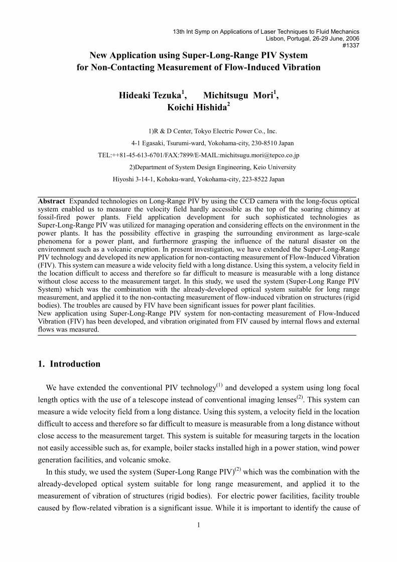
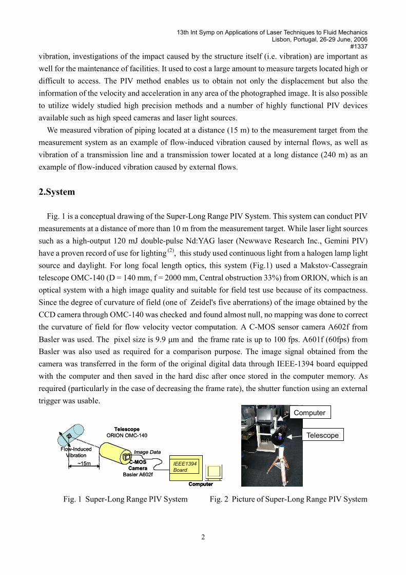
Fig. 1 is a conceptual drawing of the Super-Long Range PIV System. This system can conduct PIV measurements at a distance of more than 10 m from the measurement target. While laser light sources such as a high-output 120 mJ double-pulse Nd:YAG laser (Newwave Research Inc., Gemini PIV) have a proven record of use for lighting (2), this study used continuous light from a halogen lamp light source and daylight. For long focal length optics, this system (Fig.1) used a Makstov-Cassegrain telescope OMC-140 (D = 140 mm, f = 2000 mm, Central obstruction 33%) from ORION, which is an optical system with a high image quality and suitable for field test use because of its compactness. Since the degree of curvature of field (one of Zeidel's five aberrations) of the image obtained by the CCD camera through OMC-140 was checked and found almost null, no mapping was done to correct the curvature of field for flow velocity vector computation. A C-MOS sensor camera A602f from Basler was used. The pixel size is 9.9 m and the frame rate is up to 100 fps. A601f (60fps) from Basler was also used as required for a comparison purpose. The image signal obtained from the camera was transferred in the form of the original digital data through IEEE-1394 board equipped with the computer and then saved in the hard disc after once stored in the computer memory. As required (particularly in the case of decreasing the frame rate), the shutter function using an external trigger was usable.
Fig. 1 Super-Long Range PIV System Fig. 2 Picture of Super-Long Range PIV System
Telescope
Computer
�����
Image Data
C-MOSCamera
Basler A602f
TelescopeORION OMC-140
Flow-Induced Vibration
Computer
IEEE1394 Board
~15m
���������������
Image Data
C-MOSCamera
Basler A602f
TelescopeORION OMC-140
Flow-Induced Vibration
Computer
IEEE1394 Board
Computer
IEEE1394 Board
~15m
13th Int Symp on Applications of Laser Techniques to Fluid Mechanics Lisbon, Portugal, 26-29 June, 2006
#1337
3
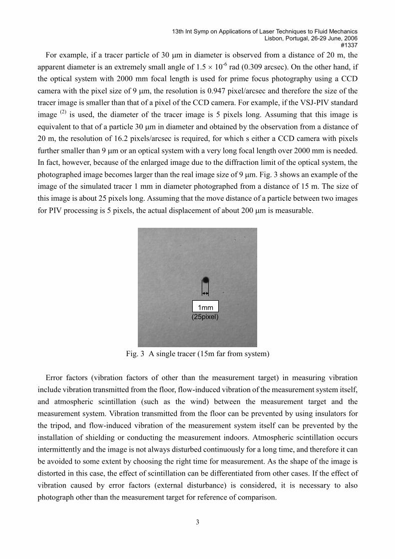
For example, if a tracer particle of 30 m in diameter is observed from a distance of 20 m, the apparent diameter is an extremely small angle of 1.5 10-6 rad (0.309 arcsec). On the other hand, if the optical system with 2000 mm focal length is used for prime focus photography using a CCD camera with the pixel size of 9 m, the resolution is 0.947 pixel/arcsec and therefore the size of the tracer image is smaller than that of a pixel of the CCD camera. For example, if the VSJ-PIV standard image (2) is used, the diameter of the tracer image is 5 pixels long. Assuming that this image is equivalent to that of a particle 30 m in diameter and obtained by the observation from a distance of 20 m, the resolution of 16.2 pixels/arcsec is required, for which s either a CCD camera with pixels further smaller than 9 m or an optical system with a very long focal length over 2000 mm is needed. In fact, however, because of the enlarged image due to the diffraction limit of the optical system, the photographed image becomes larger than the real image size of 9 m. Fig. 3 shows an example of the image of the simulated tracer 1 mm in diameter photographed from a distance of 15 m. The size of this image is about 25 pixels long. Assuming that the move distance of a particle between two images for PIV processing is 5 pixels, the actual displacement of about 200 m is measurable.
Fig. 3 A single tracer (15m far from system)
Error factors (vibration factors of other than the measurement target) in measuring vibration include vibration transmitted from the floor, flow-induced vibration of the measurement system itself, and atmospheric scintillation (such as the wind) between the measurement target and the measurement system. Vibration transmitted from the floor can be prevented by using insulators for the tripod, and flow-induced vibration of the measurement system itself can be prevented by the installation of shielding or conducting the measurement indoors. Atmospheric scintillation occurs intermittently and the image is not always disturbed continuously for a long time, and therefore it can be avoided to some extent by choosing the right time for measurement. As the shape of the image is distorted in this case, the effect of scintillation can be differentiated from other cases. If the effect of vibration caused by error factors (external disturbance) is considered, it is necessary to also photograph other than the measurement target for reference of comparison.
1mm(25pixel)
13th Int Symp on Applications of Laser Techniques to Fluid Mechanics Lisbon, Portugal, 26-29 June, 2006
#1337
4
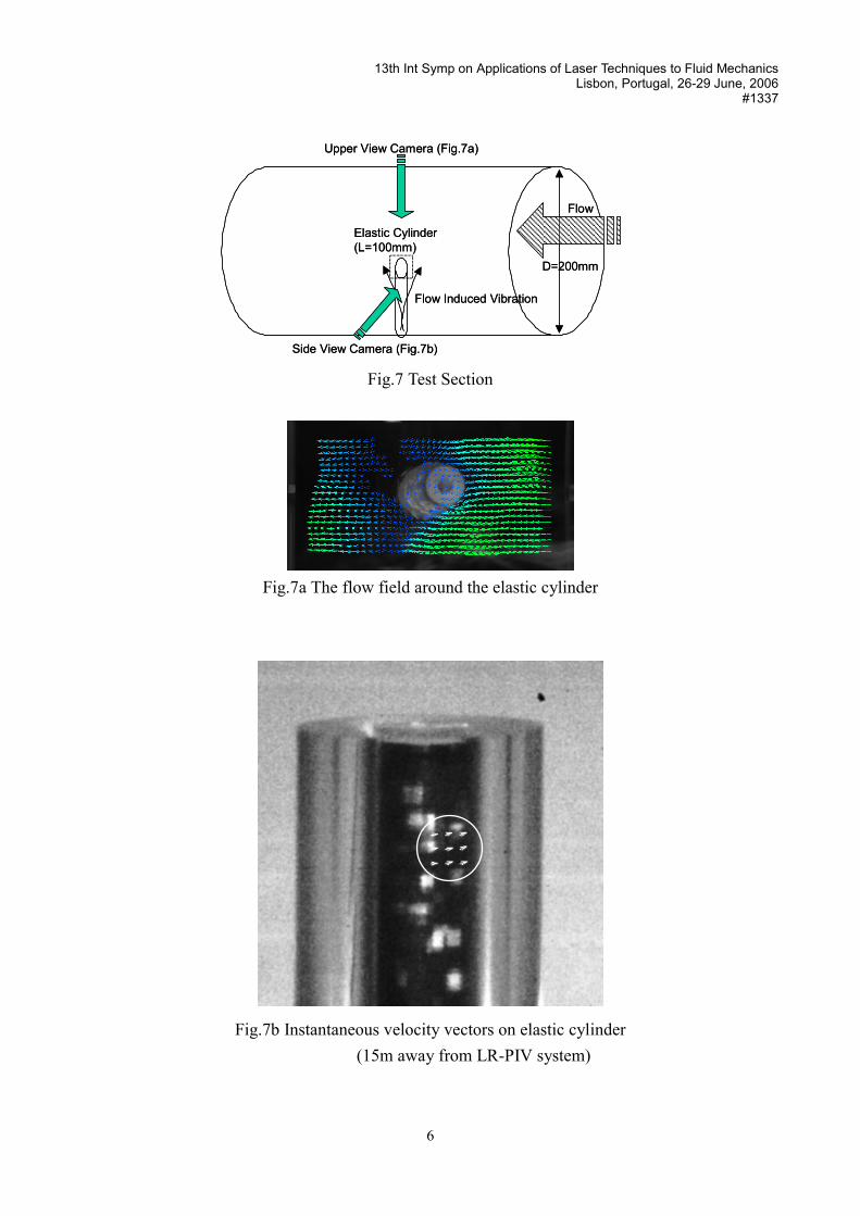
3. Measurement Test 3.1 Measurement of flow-induced vibration of piping (internal flows)
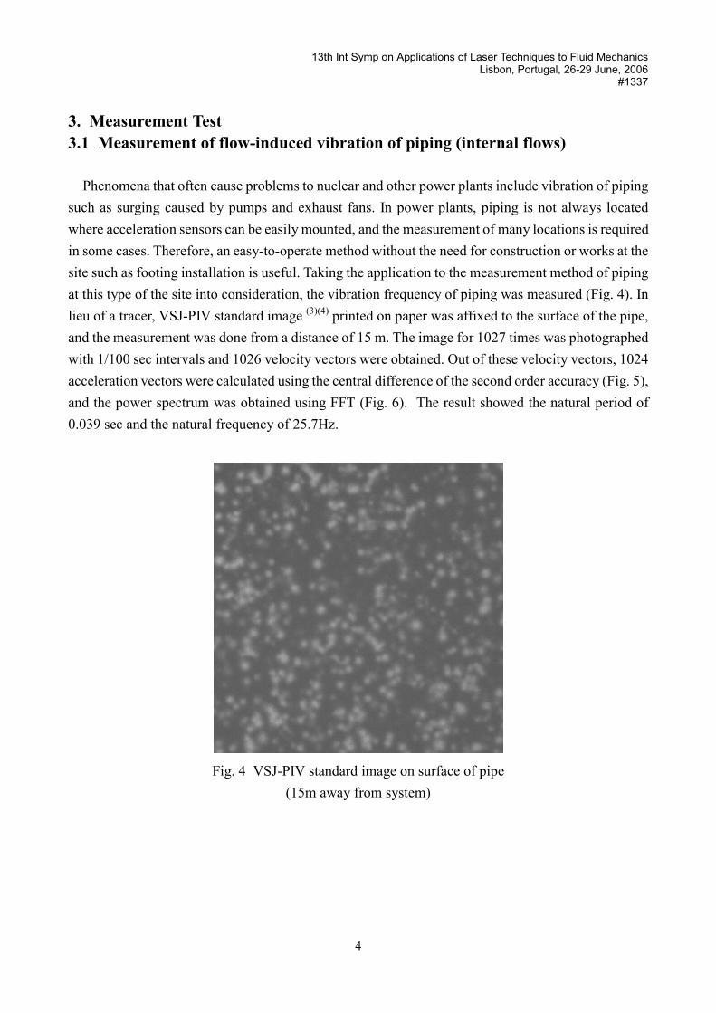
Phenomena that often cause problems to nuclear and other power plants include vibration of piping such as surging caused by pumps and exhaust fans. In power plants, piping is not always located where acceleration sensors can be easily mounted, and the measurement of many locations is required in some cases. Therefore, an easy-to-operate method without the need for construction or works at the site such as footing installation is useful. Taking the application to the measurement method of piping at this type of the site into consideration, the vibration frequency of piping was measured (Fig. 4). In lieu of a tracer, VSJ-PIV standard image (3)(4) printed on paper was affixed to the surface of the pipe, and the measurement was done from a distance of 15 m. The image for 1027 times was photographed with 1/100 sec intervals and 1026 velocity vectors were obtained. Out of these velocity vectors, 1024 acceleration vectors were calculated using the central difference of the second order accuracy (Fig. 5), and the power spectrum was obtained using FFT (Fig. 6). The result showed the natural period of 0.039 sec and the natural frequency of 25.7Hz.
Fig. 4 VSJ-PIV standard image on surface of pipe (15m away from system)
13th Int Symp on Applications of Laser Techniques to Fluid Mechanics Lisbon, Portugal, 26-29 June, 2006
#1337
5
Fig. 5 Time domain (Pipe)
Fig. 6 Power spectrum (Pipe)
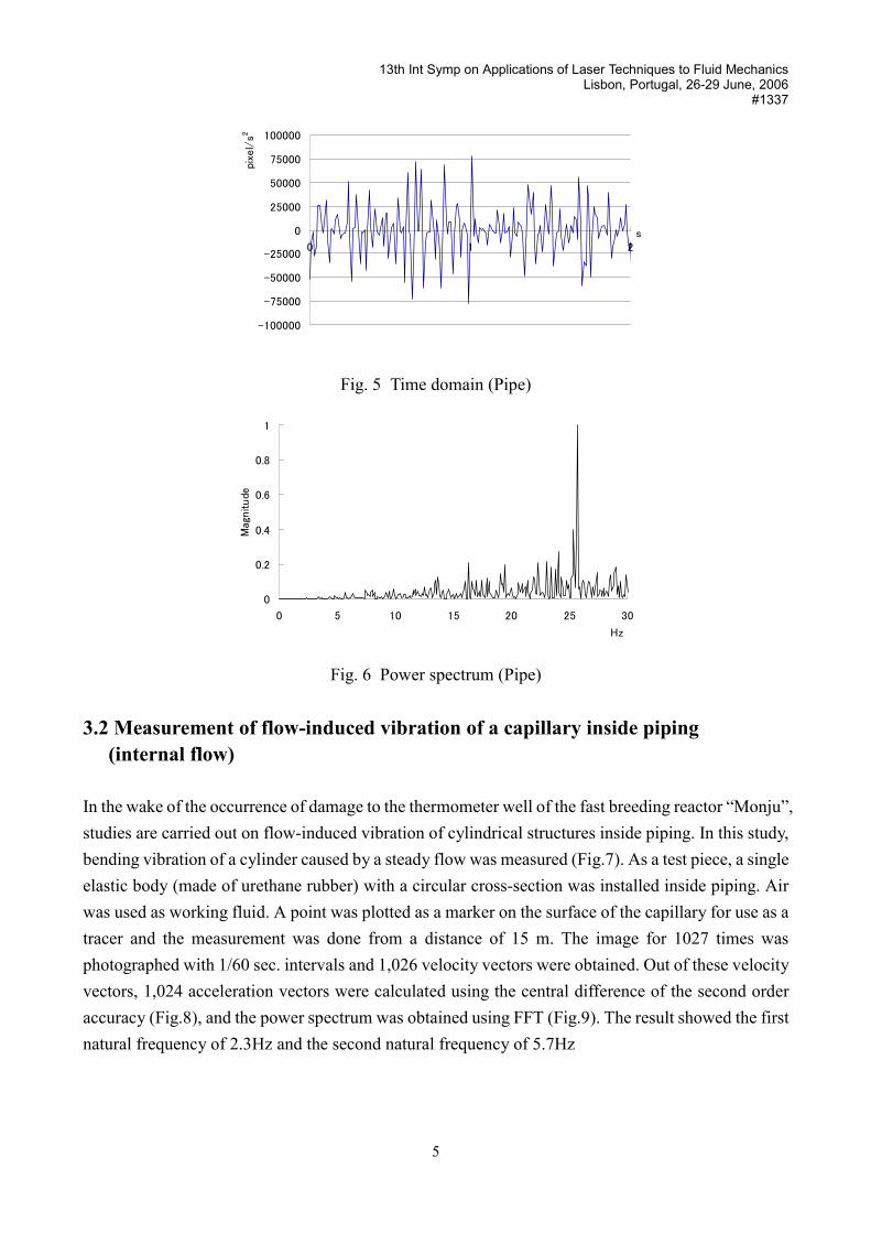
3.2 Measurement of flow-induced vibration of a capillary inside piping (internal flow)
In the wake of the occurrence of damage to the thermometer well of the fast breeding reactor “Monju”, studies are carried out on flow-induced vibration of cylindrical structures inside piping. In this study, bending vibration of a cylinder caused by a steady flow was measured (Fig.7). As a test piece, a single elastic body (made of urethane rubber) with a circular cross-section was installed inside piping. Air was used as working fluid. A point was plotted as a marker on the surface of the capillary for use as a tracer and the measurement was done from a distance of 15 m. The image for 1027 times was photographed with 1/60 sec. intervals and 1,026 velocity vectors were obtained. Out of these velocity vectors, 1,024 acceleration vectors were calculated using the central difference of the second order accuracy (Fig.8), and the power spectrum was obtained using FFT (Fig.9). The result showed the first natural frequency of 2.3Hz and the second natural frequency of 5.7Hz
13th Int Symp on Applications of Laser Techniques to Fluid Mechanics Lisbon, Portugal, 26-29 June, 2006
#1337
6
D=200mm
Flow��������������������������������������������������������������������������������������������������������������������������������
���������
������Elastic Cylinder
(L=100mm)
Flow Induced Vibration
Upper View Camera (Fig.7a)
Side View Camera (Fig.7b)
D=200mm
Flow��������������������������������������������������������������������������������������������������������������������������������
���������
������Elastic Cylinder
(L=100mm)
Flow Induced Vibration
Upper View Camera (Fig.7a)
Side View Camera (Fig.7b)
Fig.7 Test Section
Fig.7a The flow field around the elastic cylinder
Fig.7b Instantaneous velocity vectors on elastic cylinder (15m away from LR-PIV system)
13th Int Symp on Applications of Laser Techniques to Fluid Mechanics Lisbon, Portugal, 26-29 June, 2006
#1337
7
Fig.8 Time domain (Elastic cylinder)
Fig.9 Power spectrum (Elastic cylinder)
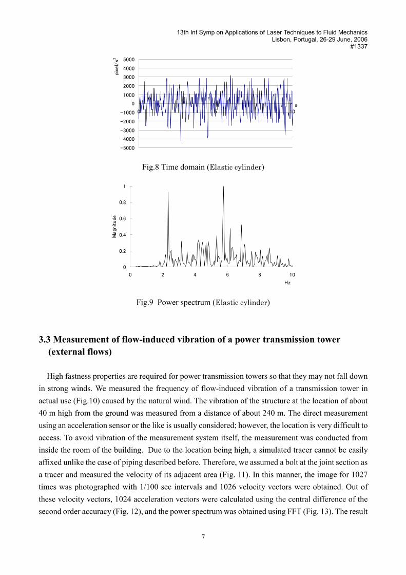
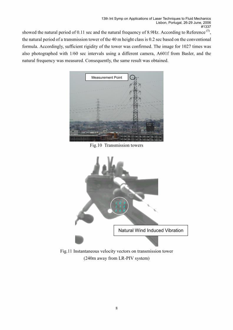
3.3 Measurement of flow-induced vibration of a power transmission tower (external flows)
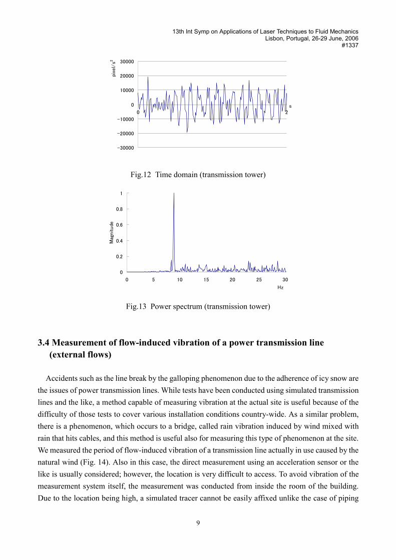
High fastness properties are required for power transmission towers so that they may not fall down in strong winds. We measured the frequency of flow-induced vibration of a transmission tower in actual use (Fig.10) caused by the natural wind. The vibration of the structure at the location of about 40 m high from the ground was measured from a distance of about 240 m. The direct measurement using an acceleration sensor or the like is usually considered; however, the location is very difficult to access. To avoid vibration of the measurement system itself, the measurement was conducted from inside the room of the building. Due to the location being high, a simulated tracer cannot be easily affixed unlike the case of piping described before. Therefore, we assumed a bolt at the joint section as a tracer and measured the velocity of its adjacent area (Fig. 11). In this manner, the image for 1027 times was photographed with 1/100 sec intervals and 1026 velocity vectors were obtained. Out of these velocity vectors, 1024 acceleration vectors were calculated using the central difference of the second order accuracy (Fig. 12), and the power spectrum was obtained using FFT (Fig. 13). The result
13th Int Symp on Applications of Laser Techniques to Fluid Mechanics Lisbon, Portugal, 26-29 June, 2006
#1337
8
showed the natural period of 0.11 sec and the natural frequency of 8.9Hz. According to Reference (5),the natural period of a transmission tower of the 40 m height class is 0.2 sec based on the conventional formula. Accordingly, sufficient rigidity of the tower was confirmed. The image for 1027 times was also photographed with 1/60 sec intervals using a different camera, A601f from Basler, and the natural frequency was measured. Consequently, the same result was obtained.
Fig.10 Transmission towers
Fig.11 Instantaneous velocity vectors on transmission tower (240m away from LR-PIV system)
Measurement Point
Natural Wind Induced Vibration
13th Int Symp on Applications of Laser Techniques to Fluid Mechanics Lisbon, Portugal, 26-29 June, 2006
#1337
9
Fig.12 Time domain (transmission tower)
Fig.13 Power spectrum (transmission tower)
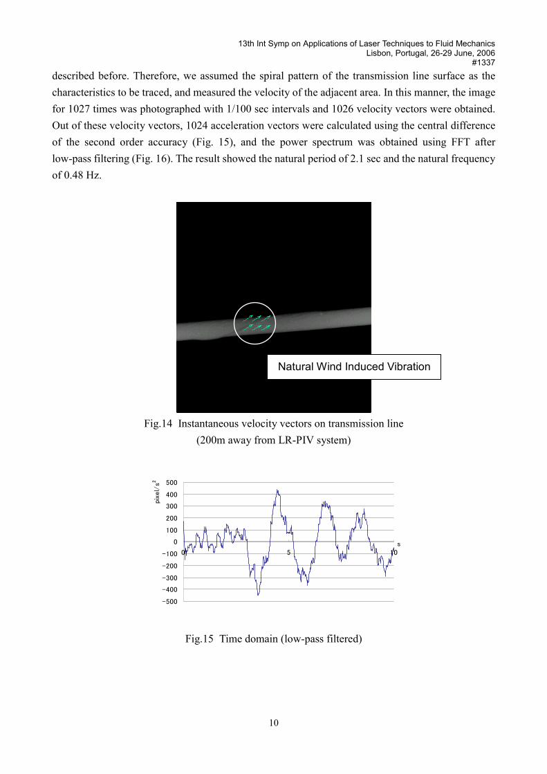
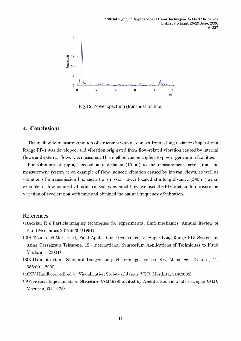
3.4 Measurement of flow-induced vibration of a power transmission line (external flows)
Accidents such as the line break by the galloping phenomenon due to the adherence of icy snow are the issues of power transmission lines. While tests have been conducted using simulated transmission lines and the like, a method capable of measuring vibration at the actual site is useful because of the difficulty of those tests to cover various installation conditions country-wide. As a similar problem, there is a phenomenon, which occurs to a bridge, called rain vibration induced by wind mixed with rain that hits cables, and this method is useful also for measuring this type of phenomenon at the site. We measured the period of flow-induced vibration of a transmission line actually in use caused by the natural wind (Fig. 14). Also in this case, the direct measurement using an acceleration sensor or the like is usually considered; however, the location is very difficult to access. To avoid vibration of the measurement system itself, the measurement was conducted from inside the room of the building. Due to the location being high, a simulated tracer cannot be easily affixed unlike the case of piping
13th Int Symp on Applications of Laser Techniques to Fluid Mechanics Lisbon, Portugal, 26-29 June, 2006
#1337
10
described before. Therefore, we assumed the spiral pattern of the transmission line surface as the characteristics to be traced, and measured the velocity of the adjacent area. In this manner, the image for 1027 times was photographed with 1/100 sec intervals and 1026 velocity vectors were obtained. Out of these velocity vectors, 1024 acceleration vectors were calculated using the central difference of the second order accuracy (Fig. 15), and the power spectrum was obtained using FFT after low-pass filtering (Fig. 16). The result showed the natural period of 2.1 sec and the natural frequency of 0.48 Hz.
Fig.14 Instantaneous velocity vectors on transmission line (200m away from LR-PIV system)
Fig.15 Time domain (low-pass filtered)
Natural Wind Induced Vibration
13th Int Symp on Applications of Laser Techniques to Fluid Mechanics Lisbon, Portugal, 26-29 June, 2006
#1337
11
Fig.16 Power spectrum (transmission line)
4. Conclusions
The method to measure vibration of structures without contact from a long distance (Super-Long Range PIV) was developed, and vibration originated from flow-related vibration caused by internal flows and external flows was measured. This method can be applied to power generation facilities.
For vibration of piping located at a distance (15 m) to the measurement target from the measurement system as an example of flow-induced vibration caused by internal flows, as well as vibration of a transmission line and a transmission tower located at a long distance (240 m) as an example of flow-induced vibration caused by external flow, we used the PIV method to measure the variation of acceleration with time and obtained the natural frequency of vibration.
References (1)Adrian R J,Particle-imaging techniques for experimental fluid mechanics. Annual Review of
Fluid Mechanics 23: 26l-304(1991) (2)H.Tezuka, M.Mori et al, Field Application Development of Super-Long Range PIV System by
using Cassegrain Telescope, 12th International Symposium Applications of Techniques to Fluid Mechanics (2004)
(3)K.Okamoto et al, Standard Images for particle-image velocimetry, Meas. Sci. Technol., 11, 685-691,(2000)
(4)PIV Handbook, edited by Visualization Society of Japan (VSJ), Morikita, 314(2002) (5)Vibration Experiments of Structure (AIJ1978) ,edited by Architectual Instisute of Japan (AIJ),
Maruzen,291(1978)