nsc heat seal manual easyseal – iii avnatmar-nsc.com/manuals/hs177_178-1.pdf · nsc . heat seal...
TRANSCRIPT

NSC HEAT SEAL MANUAL
EASYSEAL – III AV
MODEL NUMBER HS177-1, HS178-1
REV0612
Natmar Services Company
139 Beattie Street . P.O. Box 6743 . Syracuse, NY 13217
Toll Free 800-798-8206 ● Local (315) 445-2419 ● Fax (315) 445-8046
Visit us on the web at www.natmar-nsc.com
1

Table of Contents
Page
Warranty…………………………………………………………………………………….......3 Unpacking & Installation……………………………………………………………………….4 ● Checking Shipment/Warnings & Cautions/Installation/Air Supply/Electrical Requirements Operation………………………………………………………………………………………..6 Heat Sealing…………………………………………………………………………………….8 ● Heat Sealing Guide Periodic Maintenance…………………………………………………………………………...9 Troubleshooting-General……………………………………………………………………....10 Troubleshooting-Heated Related Problems & Air Links……………………………………....11 Digital Temperature Control……………………………………………………………………13 Re-setting the Heat Controller………………………………………………………………….14 Touch Board Adjustment……………………………………………………………………….17 Low Air Pressure Switch……………………………………………………………………….18 Schematic Drawings Machine-General (M-1)…………………………………………………………………………19 Frame Assembly (M-2)…………………………………………………………………………20 Upper Head Mounting (M-3)……………………………………………………………………21 Lower Head Assembly (M-5)…………………………………………………………………...22 Front Cover Assembly (M-6)……………………………………………………………………23 Frame Assembly AV Upper (M-9)……………………………………………………………...24 Start and Repeat Switch Assembly (M-10)……………………………………………………...25 Air Cylinder Assembly (P-1)…………………………………………………………………….26 Solenoid Valve Assembly (P-2)…………………………………………………………………27 Air Regulator & Pressure Switch Assembly…………………………………………………….28 Air Filter/Air Gauge Assembly (P-4)……………………………………………………………29 Rotary Cylinder Assembly (P-5)………………………………………………………………...30 Manual Air Valve Assembly (P-6)………………………………………………………………31 Pneumatic Diagram (P-7)………………………………………………………………………..32 Pneumatic Parts List (P-8)……………………………………………………………………….33 Wiring Diagram-120 Volt (E-1)…………………………………………………………………34 Wiring Diagram-240 Volt (E-2)…………………………………………………………………35 70145 Heat Controller Set Up Instructions……………………………………………………...36 70184 Timer, Set-Up procedure for Replacement………………………………………………39
2
Natmar Services Company
139 Beattie Street ● P.O. Box 6743 ● Syracuse, NY 13217
Tool Free 800-798-8206 ● Local (315) 445-2419 ● Fax (315) 445-8046
Warranty For Heat Seal Machine
Natmar Services Company, Syracuse, New York (“Seller”) warrants this Heat Seal Machine to be free from defects in material and workmanship under normal use service. Any part which proves to be defective in material or workmanship within one year of the date of original purchase for use, will be repaired or replaced, at Seller’s option, free of service or labor charges, with a new or functionally operative part. Seller’s liability under the warranty shall be limited to repairing or replacing at its own factory or through an authorized service distributor or dealer, material which is determined by Seller to have been defective in manufacturer and upon which is a claim has been made by the original purchaser or user to Seller (or an authorized distributor or dealer) within the warranty period. An authorized officer Of Seller will honor claims under tins warranty only upon written approval. Approved return of parts or products will be on a prepaid transportation charges basis only. Claims under this Warranty will be honored only upon Seller’s determination that the claim is covered by this Warranty, and Seller shall incur no obligation under this warranty prior to such determination This warranty does not supply: (1) To any machinery or equipment which has been altered or repaired , except by Seller or its authorized representatives, or (2) to any machinery or equipment which has been subject to misuse, or accident, including, without limitation, use an operation of such machinery or equipment while parts are loose, broken, out of order, or damaged by the elements. Parts replaced under this warranty and warranted only through the remainder of the original Warranty. Any and all claims for warranty service must include such information as Sellers designates, and shall include specifically the serial number of each unit (if appropriate). The forgoing shall constitute the sole and exclusive remedy of any using purchaser and the sole an exclusive liability of Seller in connection with this product. THIS WARRANTY IS IN LIEU OF ALL OTHER WARRANTIES, EXPRESS, IMPLIED OR STATUTORY, INCLUDING OTHER OBLIGATIONS OR LIABILITIES OF SELLER, INCLUDING ANY TORT LIABILTY, FOR NEGLIGENT DESIGN OR MANUFATURE OF THIS PRODUCT OR OTHERWISE. It is expressed agreed that buyer shall not be entitled to recover any incidental or consequential damages, as those terms are defined in the Uniform Commercial Code, and that Buyer shall have no right of rejection or of revocation of acceptance of any part of revocation of acceptance of any part or all the goods covered hereby. Natmar services Company reserves the right to make changes in design and changes or improvements upon its product without imposing any obligation upon itself to install the same upon its product previously manufactured.
3

1. UNPACKING AND INSTALLATION
1-1 CHECKING SHIPMENT A. The machine is shipped fully assembled B. Check items received against item on the packing slip.
Thoroughly check the machine for any damage that may have occurred in transit. Advise the carrier of any damage or missing components within seven (7) days of
receipt. 1-2 NOTES, CAUTIONS AND WARNINGS
Notes, cautions and warnings are used throughout the manual to emphasize important and critical instructions. NOTE: A note is used to emphasize operation procedures, practices, etc…essential for proper use. CAUTION: A caution is used to emphasize operating procedures, practices, etc., which if not strictly observed may result in damage to the machine. WARNING: A warning is used to emphasize operation procedures, practices, etc., which if not strictly followed may result in person injury or loss of life.
1-3 INSTALLATION
The machine may be installed on any level surface capable of supporting its weight. It should be located at least 12 inches from the closest object for ease of maintenance, and should be set back at least 6 inches from the edge of the bench or table on which it rests. Consistent with these requirements, the machine may be further arranged for maximum operator comfort and efficiency.
4

1-4 MACHINE SAFETY GUARDING AND DEVICES
The machine is equipped with safety guarding and devices to prevent injury to the machine operator. To provide the maximum level of safety to the operator, these guards and devices must remain in place and must not be altered in any manner!
1-5 MACHINE SAFETY GUARDING AND DEVICES Continued
The following pictures illustrate the proper installation and maintenance of the Touch Guard Safety Device.
5
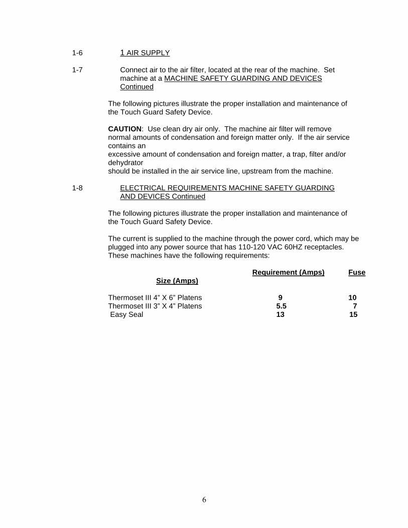
1-6 1 AIR SUPPLY
1-7 Connect air to the air filter, located at the rear of the machine. Set machine at a MACHINE SAFETY GUARDING AND DEVICES Continued
The following pictures illustrate the proper installation and maintenance of the Touch Guard Safety Device.
CAUTION: Use clean dry air only. The machine air filter will remove normal amounts of condensation and foreign matter only. If the air service contains an excessive amount of condensation and foreign matter, a trap, filter and/or dehydrator should be installed in the air service line, upstream from the machine.
1-8 ELECTRICAL REQUIREMENTS MACHINE SAFETY GUARDING AND DEVICES Continued
The following pictures illustrate the proper installation and maintenance of the Touch Guard Safety Device.
The current is supplied to the machine through the power cord, which may be plugged into any power source that has 110-120 VAC 60HZ receptacles. These machines have the following requirements:
Requirement (Amps) Fuse
Size (Amps)
Thermoset III 4” X 6” Platens 9 10 Thermoset III 3” X 4” Platens 5.5 7 Easy Seal 13 15
6

1-9 ELECTRICAL REQUIREMENTS Continued
WARNING: ELECTRICAL GROUNDING INSTRUCTIONS The power supply cord has a 3-prong grounding for your personal safety. It must be plugged into a mating 3-prong grounding type wall receptacle, grounded in accordance with the National Electrical Code and local codes and ordinances.
DO NOT REMOVE THE GROUND PLUG!
DO NOT USE AN EXTENSION CORD!
7
2. Operation
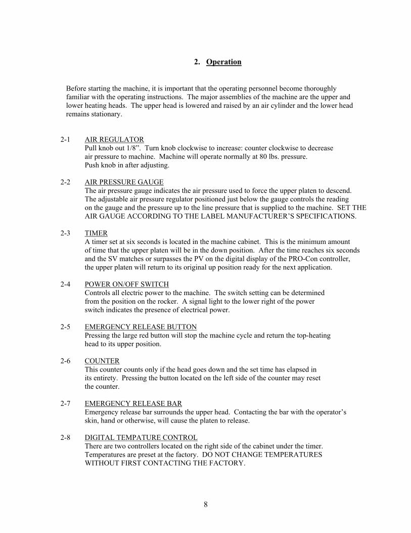
Before starting the machine, it is important that the operating personnel become thoroughly familiar with the operating instructions. The major assemblies of the machine are the upper and lower heating heads. The upper head is lowered and raised by an air cylinder and the lower head remains stationary. 2-1 AIR REGULATOR Pull knob out 1/8”. Turn knob clockwise to increase: counter clockwise to decrease air pressure to machine. Machine will operate normally at 80 lbs. pressure. Push knob in after adjusting. 2-2 AIR PRESSURE GAUGE The air pressure gauge indicates the air pressure used to force the upper platen to descend. The adjustable air pressure regulator positioned just below the gauge controls the reading on the gauge and the pressure up to the line pressure that is supplied to the machine. SET THE AIR GAUGE ACCORDING TO THE LABEL MANUFACTURER’S SPECIFICATIONS. 2-3 TIMER A timer set at six seconds is located in the machine cabinet. This is the minimum amount of time that the upper platen will be in the down position. After the time reaches six seconds and the SV matches or surpasses the PV on the digital display of the PRO-Con controller, the upper platen will return to its original up position ready for the next application. 2-4 POWER ON/OFF SWITCH Controls all electric power to the machine. The switch setting can be determined from the position on the rocker. A signal light to the lower right of the power switch indicates the presence of electrical power. 2-5 EMERGENCY RELEASE BUTTON Pressing the large red button will stop the machine cycle and return the top-heating head to its upper position. 2-6 COUNTER This counter counts only if the head goes down and the set time has elapsed in its entirety. Pressing the button located on the left side of the counter may reset the counter. 2-7 EMERGENCY RELEASE BAR Emergency release bar surrounds the upper head. Contacting the bar with the operator’s skin, hand or otherwise, will cause the platen to release. 2-8 DIGITAL TEMPATURE CONTROL There are two controllers located on the right side of the cabinet under the timer. Temperatures are preset at the factory. DO NOT CHANGE TEMPERATURES WITHOUT FIRST CONTACTING THE FACTORY.
8

2-9 MACHINE SHUTDOWN FEATURE – AIR PRESSURE AND TEMPERATURE this feature is designed to insure the machine is being operated at the proper sealing conditions. The machine will cease to operate under the following conditions: A. Air pressure drops below 20 #. B. Temperature of either heat controller deviates 15◦ from the set point. C. Temperature deviates +/-20◦ from the 380◦ factory set Pro-Con Set Value (SV-green display).
9
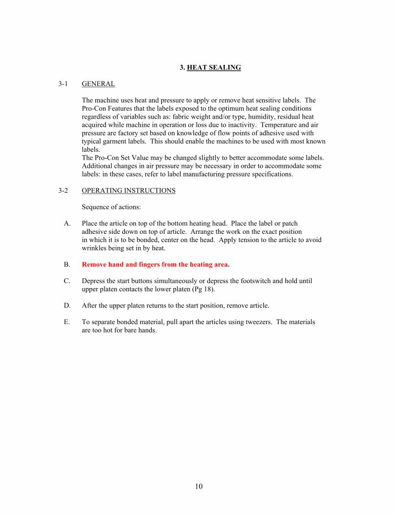
3. HEAT SEALING 3-1 GENERAL The machine uses heat and pressure to apply or remove heat sensitive labels. The Pro-Con Features that the labels exposed to the optimum heat sealing conditions regardless of variables such as: fabric weight and/or type, humidity, residual heat acquired while machine in operation or loss due to inactivity. Temperature and air pressure are factory set based on knowledge of flow points of adhesive used with typical garment labels. This should enable the machines to be used with most known labels. The Pro-Con Set Value may be changed slightly to better accommodate some labels. Additional changes in air pressure may be necessary in order to accommodate some labels: in these cases, refer to label manufacturing pressure specifications. 3-2 OPERATING INSTRUCTIONS Sequence of actions: A. Place the article on top of the bottom heating head. Place the label or patch adhesive side down on top of article. Arrange the work on the exact position in which it is to be bonded, center on the head. Apply tension to the article to avoid wrinkles being set in by heat. B. Remove hand and fingers from the heating area. C. Depress the start buttons simultaneously or depress the footswitch and hold until upper platen contacts the lower platen (Pg 18). D. After the upper platen returns to the start position, remove article. E. To separate bonded material, pull apart the articles using tweezers. The materials are too hot for bare hands.
10

4. PERIODIC MAINTANCE
Machine malfunctions and damage to articles being processed can be minimized by performing the periodic inspection below. These inspections should be made daily. 4-1 INSPECTION PROCEDURE A. Check temperature, pressure and time setting. If these settings have been changed, return these settings to their original set point. B. Check external airline filters and traps. Clean out as required. Periodically, the filter element and bowl should be removed and cleaned. To remove the filter element, the filter must be depressurized and the bowl removed. The bowl should be washed with soapy water. WARNING: Never disassemble unit under pressure. Relieve all pressure before disassembly of machine.
The filter element can be washed in the same solution as the bowl. After washing, dry air filter element by blowing compressed air from the inside of the filter element, outwards. Replace and reassemble bowl.
CAUTION: Never wash transparent bowls with gasoline or any fluids containing the following chemicals: Acetone, Ethyl, Acetate, Ethylene, Dichloride, or Toluene, Chemical of this nature will structurally weaken the filter bowl. Filter bowls that are structurally weakened, can rupture causing serious injury to machine operates. C. Inspect Teflon head covers for damage or wear. Replace as necessary. Wiping off any sticking adhesive periodically will help to extend the life of Teflon covers. D. Check safety bar for damage and for proper operation. E. Clean the machine. The machine should be thoroughly dusted at the end of each day’s operation. NOTE: Occasionally, adhesive, lint, etc., may build up on the underside of the heating head and platen cover. This build up can be removed by starting the machine and wiping the build up off with a cloth after heating heads are warm. WARNING: Always disconnect the power plug from the outlet and the air line before performing repairs. THE USE OF SYNTHETIC OILS IN THIS MACHINE WILL HAVE A NEGATIVE EFECT ONTHE “O” RINGS IN THE AIR VALVE CAUSING THE MACHINE TO
BECOME INOPERABLE. WE RECOMMEND THAT NO OIL BE PLACED INTO THE AIR OF THIS MACHINE.
11

THIS MACHINE
5. TROUBLE SHOOTING STANDARD MODELS ONLY
Trouble Possible Cause Corrective Action Head will not descend ● Defective start/stop switch
● Timer Switch ● Top head not in position ● Defective anti-tie down relay ● Defective air valve ● Defective touch control board
● Replace switch or adjust start switch ● Replace timer or relay ● Move head to full right or left position ● Check for faulty regulator ● Replace Valve ● Replace cylinder ● Reduce touch sensitivity-bypass touch board, call Natmar for instructions
Head will not rise ● Defective timer or relay ● Defective valve
● Replace timer or relay ● Replace valve
Head descends or rises too slowly
● Improper air pressure ● Check and adjust air regulator
Head will not remain down ● Defective Timer ● Improper timer setting ● Damp Clothes ● Sensitivity on touch
● Replace timer or relay ● Adjust timer ● Reduce sensitivity by turning knob
No heat or too much heat at one heating head
● Defective thermocouple-Easy Seal ● Defective temp controller- Easy Seal ● Defective heating head ● Loose or broken wire connection ● Defective head control relay
● Replace thermocouple ● Replace temperature controller ● Replace heating pads ● Restore wire connections ● Replace relay
Weak bond ● Timer set incorrectly for operation being performed ● Temperature too high or too low ● Incorrect air pressure ● Defective tapes
● Adjust timer ● Adjust temperature of heads ● Adjust air regulator ● Call manufacturer of tapes to obtain suggested sealing conditions
Audible air leaks or “blow-by”in valve
● Defective valve ● Sticking valve ● Cylinder “O” ring or piston cup worn
● Replace valve ● Replace valve ● Repair or replace air cylinder
12

` Troubleshooting Heat Related Problems & Air Links
Head will not descend: ● Check air gauge and air pressure ● Check if timer is operating. If the timer is operating properly, then check the timer with a voltage meter to see if you are getting power out of the timer and to the air valve. IF YES, then the air valve (part # 2324 or # 2959 on 100 volt machine) is defective. IF NO. the timer (part # 2860) is defective. ● Check the touch board (part # 2025). The green light should be “ON” and the red light should be “OFF” for proper operation. See page titled “installation and use of model 2025 touch board”. If the machine then operates, the board could be defective. ● Check the anti-tie down relay (ATD Relay). The blue plug device that is located behind the ON/OFF switch. Swap relays to see if problem follows with the relay, if so, replace the anti-tie down (ATD Relay-part # 3300) ● Next, check for voltage on the timing circuit by placing one probe on the terminal strip (part # 1660) where the white wires connect. Carefully place the other probe one at a time on the following: NC on the touch control board (part # 2025) C on the red stop switch (part # 2823) RED wires on the terminal strip (part # 1660) C on the single start switch (part # 2823) C on the double start switch (part # 3305) *There are two poles; power should be on one pole at a time, alternating when the single start button is pushed. Unplug the ATD Relay ( part # 3300). There should be power on #3. Press both green buttons and there should be power on #2 & #8 (may be helpful to have another person assist in pressing buttons.) Plug the ATD Relay back in and check for power at #7 on the timer (part # 2860) ● By now the defective part should have been located. If not, call Natmar Services Company @ 1-800-798-8206 for assistance.
13

Head will not rise: ● Turn the machine off by moving the ON/OFF rocker switch (part # 2150) to the OFF position. If the head remains down, then the Air valve (part # 2324) is defective. ● Check the timer for proper setting. Make sure the last digit is on the S for seconds. Head will not remain down: ● Check the timer for proper setting. Make sure the last digit is on S for seconds. ● Make sure the garment are dry. Wet garment will trigger the safety bar feature, preventing the head from staying down. ● See page titled “installation and use of model 2025 touch control board” for proper setup and operation of the touch control board. You may have to reset the sensitivity. Actuator collar must make contact with the switch # 2055-62. Actuator collar is located at the top of the guide rod. Guide rods screws into the upper head mounting plate. Tighten guide rod by turning clockwise. Adjust switch to ensure that actuator collar is making contact with switch No heat on one side: ● Check to see if heat controller is set at the proper setting. Check SV setting on the controller (green number) ● Check to see if heat controller is calling for heat. Out light should be showing ON. If heat controller is not ON the thermocouple could be bad. Replace the thermocouple (part # 2061) ● Switch heat controllers between the two heads. If the problem follows the controller, the controller should be replaced. ● Check he voltage between the white wire on the terminal strip and #2 on the solid-state relay (part # 3568). If there is no voltage, replace the relay. ● Remove cover on rear of head and check for voltage between white and black wire. If there is voltage, the head is bad. Replace heating head (part # 23180). If there is no voltage, check for broken wire leading to the heating head. AUDIBLE AIR LEAK For air leaking around the shaft of the cylinder: ● Repair Air Cylinder with repair kit #2612a Audible Air leak out of muffler on air valve ● Air leaks when head is up: Remove airline from top of air cylinder and check if air is coming out of cylinder. If yes, replace cylinder internal seals (part # 2612B). ● If no ,replace air valve (part # 2324) Air leaks when head is down: ● Unplug machine and shut off air supply to the machine. Remove the airline between air valve and bottom of cylinder (at the air valve # 2324). Turn air back on (air will come out of the air- line) and press the small white button on the right side of the air valve. check for air coming out of the airline while the button is in. If yes, replace the cylinder’s internal seals (repair kit # 2612B) ● If no, replace air valve # 234.
14

15
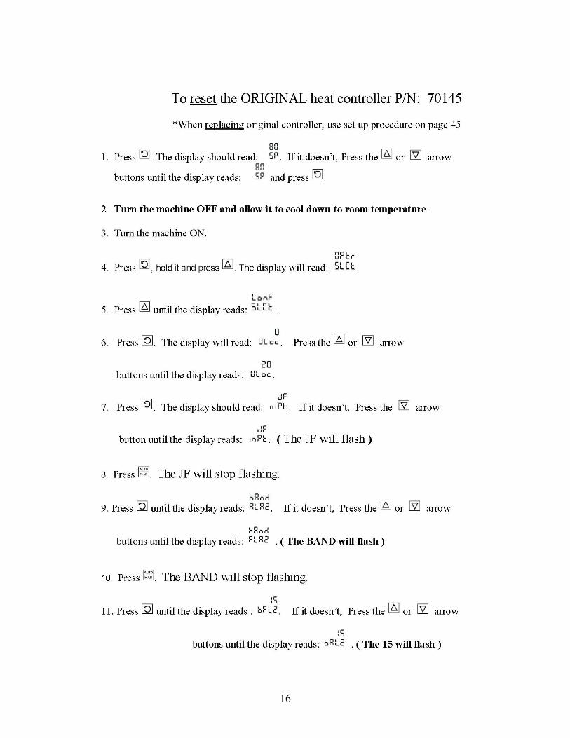
16
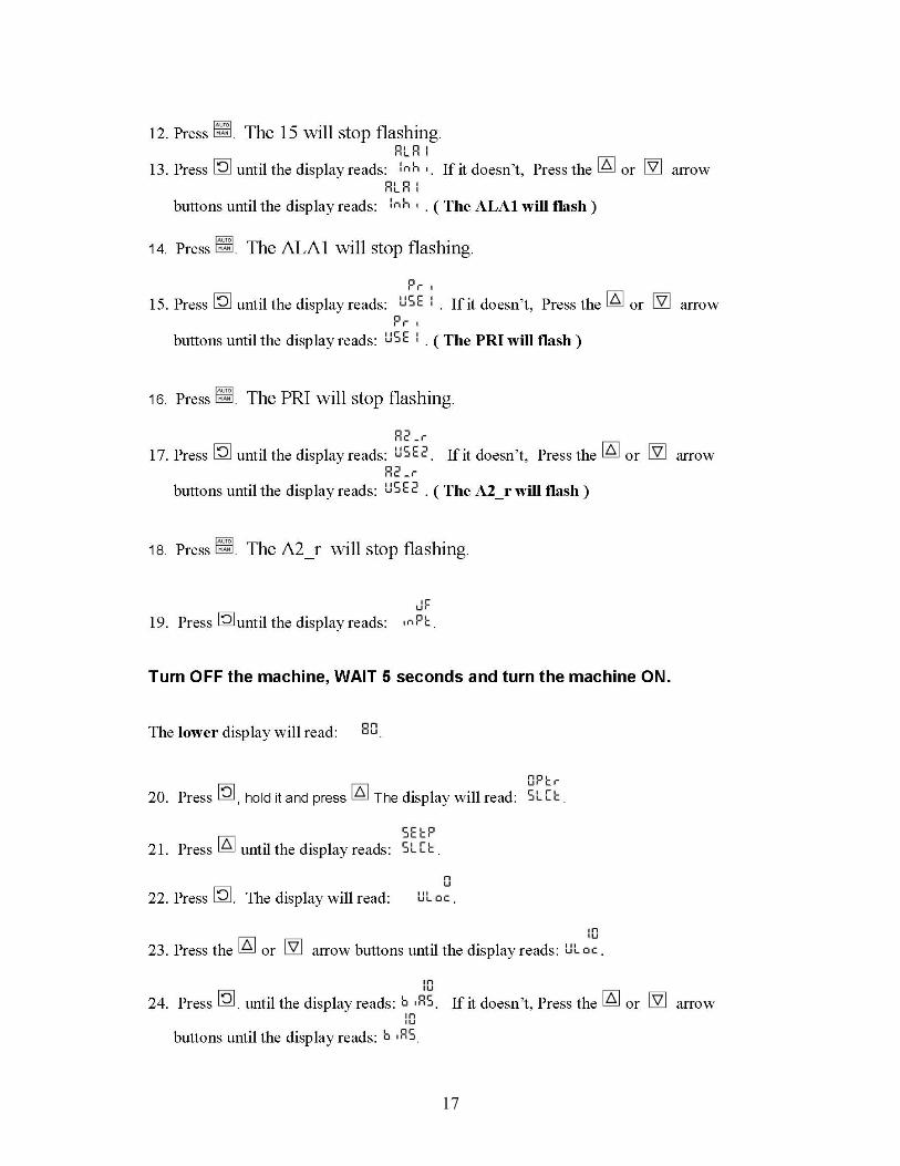
17

18

Touch Control board adjustment procedure
1. Switch the machine to the off position and unplug the line cord from power source. 2. Remove the machine back cover. The Touch board is located inside of the machine case on the right hand side. 3. Remove the touch Guard sensor Wire form the Touch Bar assembly. 4. Plug in the machine line cord. To the power source, and allow the machine to come up to operating temperature. 5. Turn the Sensor Detect Adjustment Screw until the Sensor Detect Lights turn off. 6. Adjust the Sensor Detect Adjustment Screw until the Sensor Detect Light turns on. 7. Reconnect the Touch Guard Sensor Wire to the Touch Bar assembly. When adjusted correctly, the Sensor Detected Light will go out. 8. Adjust the trigger Adjustment until the Trigger Light turns on when you touch the Touch Bar assembly with one finger. 9. If the Touch Board operates erratically, turn off the machine, unplug the line cord from the power source, and follow the instruction to test the Touch Guard Sensor wire. 10. If the Touch Board will not adjust or operate correctly, turn off the machine, unplug the line cord from the power source, and follow the instructions to bypass the Touch Board to test the machine
19
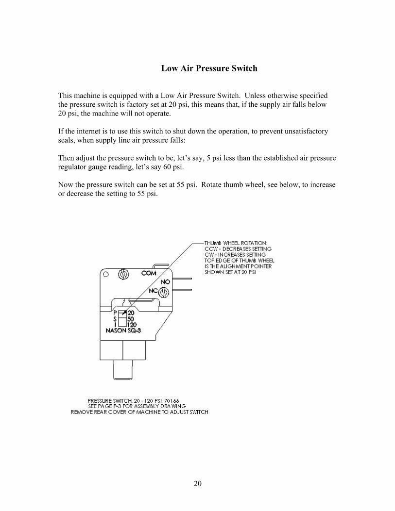
Low Air Pressure Switch This machine is equipped with a Low Air Pressure Switch. Unless otherwise specified the pressure switch is factory set at 20 psi, this means that, if the supply air falls below 20 psi, the machine will not operate. If the internet is to use this switch to shut down the operation, to prevent unsatisfactory seals, when supply line air pressure falls: Then adjust the pressure switch to be, let’s say, 5 psi less than the established air pressure regulator gauge reading, let’s say 60 psi. Now the pressure switch can be set at 55 psi. Rotate thumb wheel, see below, to increase or decrease the setting to 55 psi.
20

TEM NO. PART NUMBER DESCRIBTION QTY.
1 FRAME ASSY, ES AV SEE PAGE M-2 1 2 UPPER HEAD, INSUL 4X6 120V SEE PAGE M-4 1 3 LOWER HEAD 4X6 120V SEE PAGE M-5 2 4 FRONT COVERS ASSY, ES AV SEE PAGE M-6 1 5 32109AV BACK COVER 1 6 21063-02-1-N SHCS-10-24X1/4 LONG 1 7 21023-01 FW-#10 1 8 21061-02-F BUTTON HD SCR 1/420X3/8 LONG 4 9 21021-09-A L’W – INT NO. 1/4 4
10 3322 ELECTRIC CAUTION DECAL 1 11 20081-18 FUSE HOLDER 15 AMP MAX
(SEE NOTE 1) 1
12 20015-24 FUSE,15AMP 250V TIME DELAY. 25X1.25 (SEE NOTE 1 )
1
13 46083 LABEL, FUSE WARING, 15AMP (SEE NOTE 1)
1
14 21977 LABEL, MODEL AND SERIAL NO. 1 15 2963 POWER CORD 15 AMP 14GA
(SEE NOTE 1) 1
16 2856 WARNING LABEL 1 17 2873 NATMAR DECAL 1 18 2861 SOCKET FOR TIMER 1 19 26002T LABEL, TOP 1 20 26002L LABEL, LEFT 1 21 26002R LABEL, RIGHT 1 22 70184 TIMER, ALLEN-BRADLEY 1 23 70186 SHIELD, PLASTIC 1 24 70185 CLIP, RETAINER 1 25 70190 LABEL, EASYSEAL AV-111 2
NOTE 1: FOR 240V MACHINE, HS 178-1, USE 10 AMP FUSE, 1734; FUSE HOLDER, 9696;
FUSE LABEL, 10A 70098; POWER CORD, 1695
21

HS 177-1 EASYSEAL AV 120V SHOWN
ITEM NO. PART NUMBER DESCRIBTION QTY.
M-2
1 30592 FRAME WELDMENT, LOWER 1 2 FRAME A V UPPER SSY, A SEE PAGE M-9 1 3 28254 GUARD, PLASTIC, AV 1 4 ACTUATOR GUIDE & SWITCH ASSY SEE PAGE M-10 1 5 28200 COLLAR, LOWER, 3” BORE SC300 1 6 2843 CONE, BEARING 2 7 2844 CUP, BEARING 2 8 21012-11 SET SC ½ LG W – CUP ½-12 X 1 9 1630 STRAIN RELIEF BUSHING 1
10 D-1454 CLAMP 3/8 CABLE 1 11 21 058-08-E PH- 6-32 X 5/8 LG 1 12 21023-22 WASHER –FLAT NO.6 1 13 2 1021-05-A L’W-INT NO.6 1 14 21051-06-A HEX NUT-6#-32 1 15 AIR FILTER ASSY, ES SEE PAGE P-4 1 16 UPP ES ER HEAD MOUNTING, SEE PAGE M-3 1
22
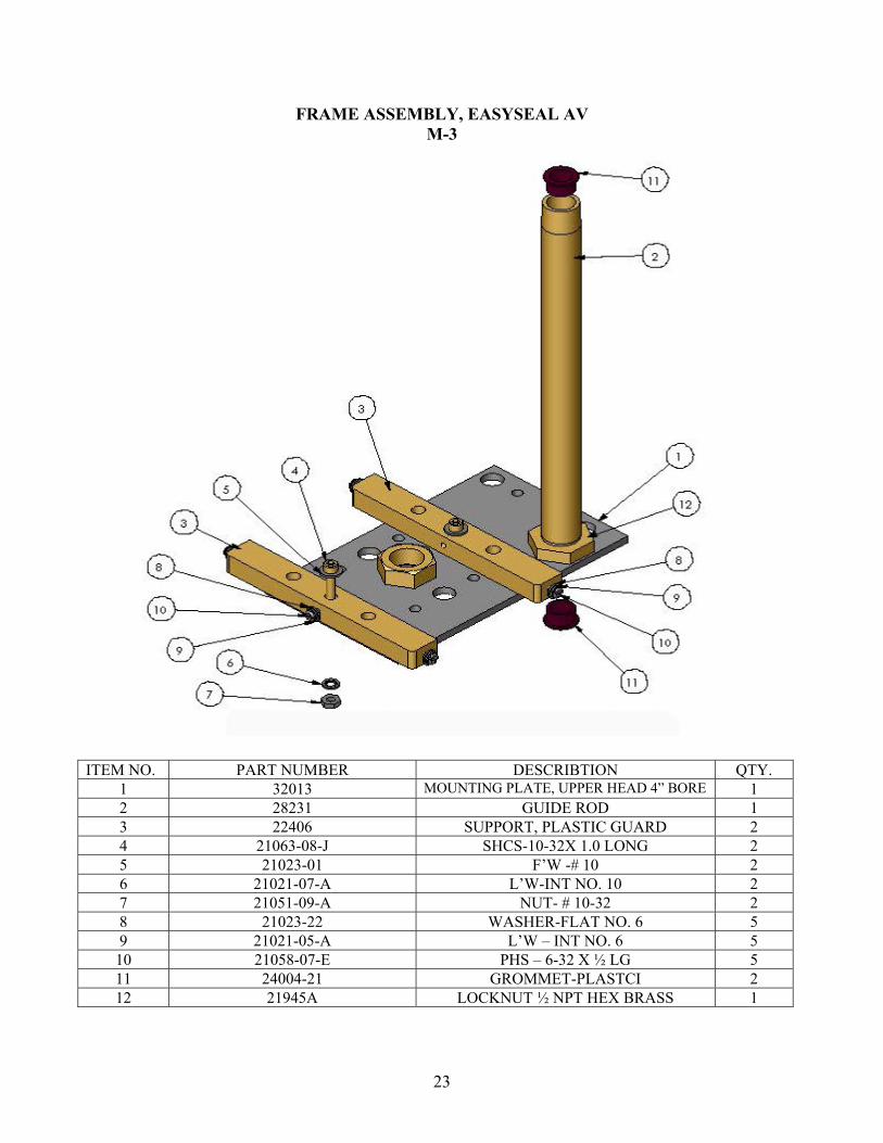
FRAME ASSEMBLY, EASYSEAL AV M-3
ITEM DESCRIBTION QTY. NO. PART NUMBER 1 32013 MOUNTING P AD 4” BORE LATE, UPPER HE 1 2 28231 GUIDE ROD 1 3 22406 SUPPORT, PLASTIC GUARD 2 4 21063-08-J SHCS-10-32X 1.0 LONG 2 5 21023-01 F’W -# 10 2 6 2 L’W-INT NO. 10 1021-07-A 2 7 21051-09-A NUT- # 10-32 2 8 21023-22 WASHER-FLAT NO. 6 5 9 2 1021-05-A L’W – INT NO. 6 5
10 21058-07-E P HS – 6-32 X ½ LG 5 11 24004-21 GROMMET-PLASTCI 2 12 21945A LOC SS KNUT ½ NPT HEX BRA 1
23

UPPER HEAD MOUNTING, ES
ITEM NO. PART NUMBER DESCRIBTION QTY.
1 36165 WIRE COVER 4X6 1 2 30344 SAFETY BAR, UPPER 4X6 1 3 21 K 063-08- SHCS ¼ 20 X 1.0 LG 2 4 21021-09-A L’W – INT NO. 1/4 4 5 21063-08-J SHC G S – 10-32 X 1.0 LON 2 6 21023-01 F’W - #10 2 7 2 L’W 10 1021-07-A – INT NO. 2 8 21051-09-A NUT - #10-32 2 9 21058-03-E PH S 6-32 X ¼ LG 1
10 21021-05-B L’W – EXT NO. 6 1 11 1200 ACORN HEX NUT ¼-20 2 12 1676 CERAMIC BUSHING W/ SPRING 1 13 70062-B TEFLON W/ PSA 4X6 1 14 2 1058-05-G PHS 10-24 X 3/8 LG 1 15 21021-07-B L’W-EXT NO. 10 1 16 30990 WIRING HARNESS, HEATER 1 17 23180 HE ) 1 ATER 4X6, 120V (SEE NOTE 1
NOTE 1: FOR A 240V MACHINE USE HEATER, #23181A
UPPER HEAD ASSEMBLY 4X6, 120X SHOWN M-4
24

ITEM NO. PART NUMBER DESCRIBTION QTY.
1 23673 MOUNTING PLATE, LOWER HEAD 1 2 23180 HEATER 46, 120V 1 3 9770 HEX COUPLING, 3/8X7/8LG #1/4 20 4 4 22012 BOTTOM HEAT INSULATOR 2 5 36165 WIRE COVER, 4X6 1 6 1676 CERAMIC BLUSHING W/SPRING 1 7 210 A 21-09- L’W – INT NO. 1/4 4 8 1200 ACORN HEX NUT ¼ 20 2 9 210 G 58-05- PHS 10-24 X 3/8 LG 3
10 21027-07-B L’W – EXT NO. 10 1 11 21021-07-A L’W – INT NO. 10 4 12 21058-03-E PHS 6-32 X ¼ LG 2 13 21021-05-A L’W – INT NO. 6 2 14 20425 PLATE, TEFLON CLAMP 2 15 23996-A TEFLON W/OUT PSA 4X6 1 16 32298 WELDMENT 4X6LOWER SAFETY BAR 1 17 21 K 063-08- SHCS ¼ -20 X 1.0 LG 1 18 21058-09-H PHS 10-32 X ¾ LG 2 19 21051-09-A NUT - #10-32 2 20 1260 HHCS ¼ -20 X 2 ½ LG 4 21 1986 HEX WIZ NUT ¼ -20 12 22 26108 P AD, FIRM 3/8 X 4 X 6 1 23 30990 WIRING HARNESS, HEATER 1
NOTE 1: FOR A 240V MACHINE. USE HEATER #23181
LOWER HEAT 4X6, 120V SHOWN M-5
25
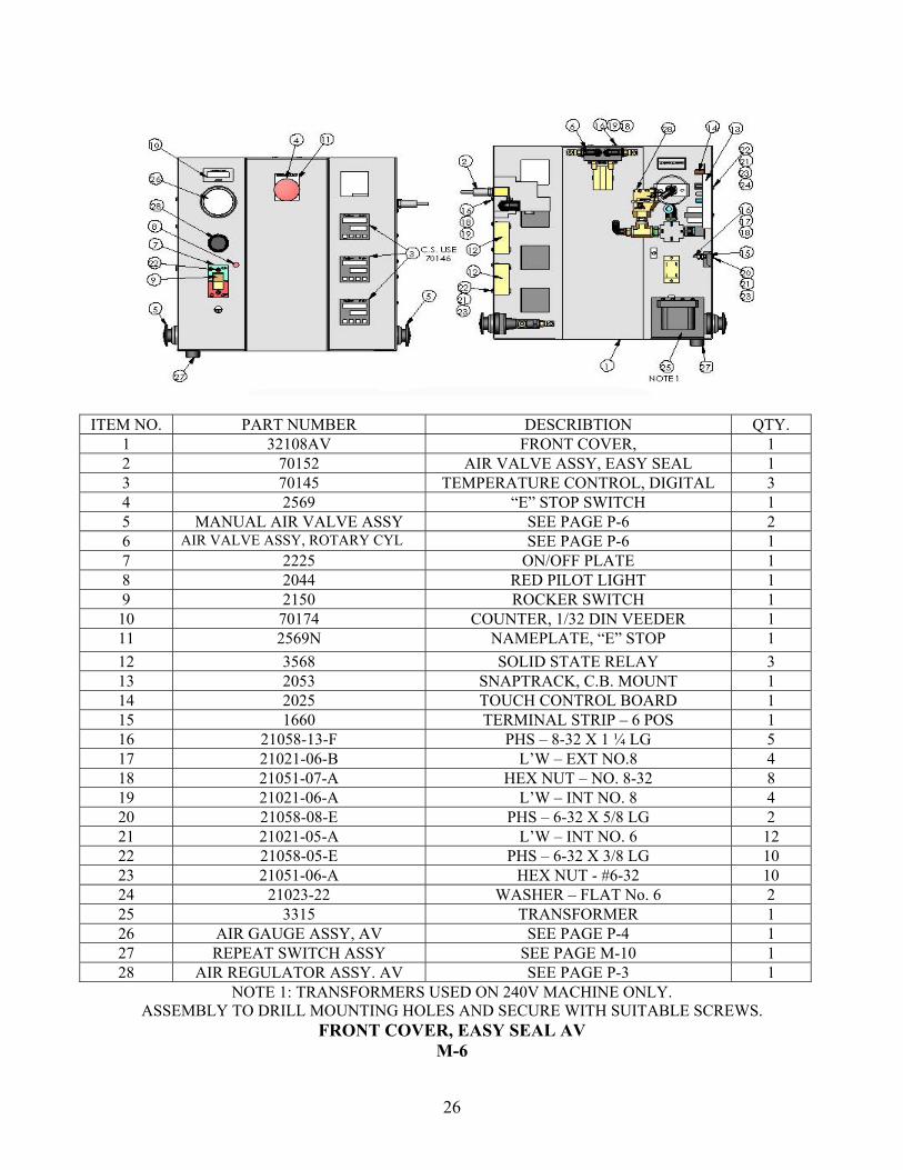
ITEM NO. PART NUMBER DESCRIBTION QTY. 1 32108AV FRONT COVER, 1 2 70152 AIR VALVE ASSY, EASY SEAL 1 3 70145 TEMPERATURE CONTROL, DIGITAL 3 4 2569 “E” STOP SWITCH 1 5 MANUAL AIR VALVE ASSY SEE PAGE P-6 2 6 AIR VALVE ASSY, ROTARY CYL SEE PAGE P-6 1 7 2225 ON/OFF PLATE 1 8 2044 RED PILOT LIGHT 1 9 2150 ROCKER SWITCH 1
10 70174 COUNTER, 1/32 DIN VEEDER 1 11 2569N NAMEPLATE, “E” STOP 1
12 3568 SOLID STATE RELAY 3 13 2053 SNAPTRACK, C.B. MOUNT 1 14 2025 TOUCH CONTROL BOARD 1 15 1660 TERMINAL STRIP – 6 POS 1 16 21058-13-F PHS – 8-32 X 1 ¼ LG 5 17 21021-06-B L’W – EXT NO.8 4 18 21051-07-A HEX NUT – NO. 8-32 8 19 21021-06-A L’W – INT NO. 8 4 20 21058-08-E PHS – 6-32 X 5/8 LG 2 21 21021-05-A L’W – INT NO. 6 12 22 21058-05-E PHS – 6-32 X 3/8 LG 10 23 21051-06-A HEX NUT - #6-32 10 24 21023-22 WASHER – FLAT No. 6 2 25 3315 TRANSFORMER 1 26 AIR GAUGE ASSY, AV SEE PAGE P-4 1 27 REPEAT SWITCH ASSY SEE PAGE M-10 1 28 AIR REGULATOR ASSY. AV SEE PAGE P-3 1
NOTE 1: TRANSFORMERS USED ON 240V MACHINE ONLY. ASSEMBLY TO DRILL MOUNTING HOLES AND SECURE WITH SUITABLE SCREWS.
FRONT COVER, EASY SEAL AV M-6
26
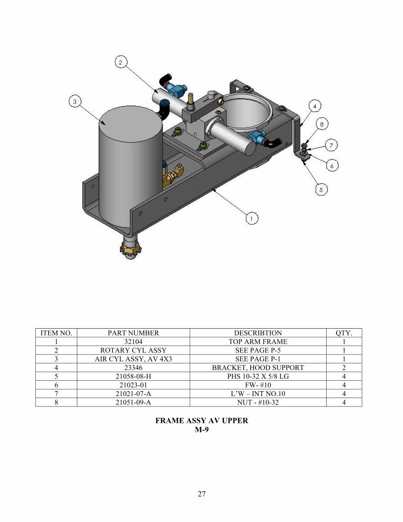
ITEM NO. PART NUMBER DESCRIBTION QTY. 1 32104 TOP ARM FRAME 1 2 ROTARY CYL ASSY SEE PAGE P-5 1 3 AIR CYL ASSY, AV 4X3 SEE PAGE P-1 1 4 23346 BRACKET, HOOD SUPPORT 2 5 21058-08-H PHS 10-32 X 5/8 LG 4 6 21023-01 FW- #10 4 7 21021-07-A L’W – INT NO.10 4 8 21051-09-A NUT - #10-32 4
FRAME ASSY AV UPPER
M-9
27
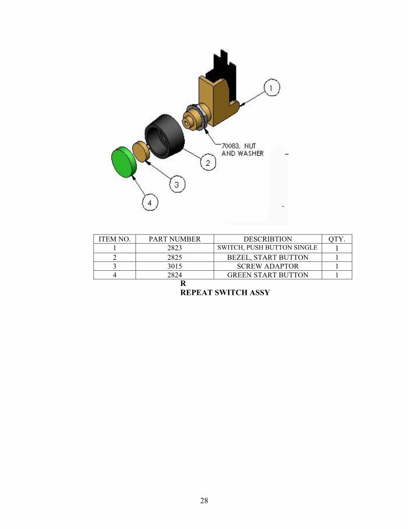
RREPEAT SWITCH ASSY
ITEM NO. PART NUMBER DESCRIBTION QTY. 1 2823 SWITCH, PUSH BUTTON SINGLE 1 2 2825 BEZEL, START BUTTON 1 3 3015 SCREW ADAPTOR 1 4 2824 GREEN START BUTTON 1
28
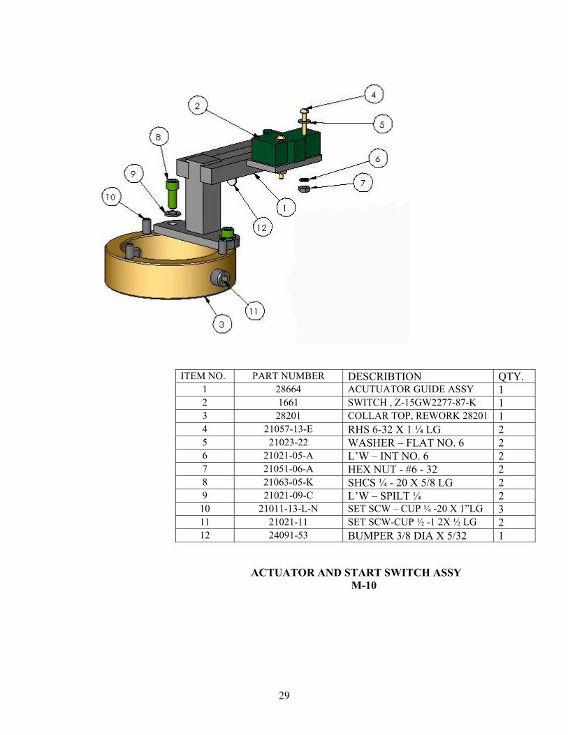
ITEM NO. PART NUMBER DESCRIBTION QTY. 1 28664 ACUTUATOR GUIDE ASSY 1 2 1661 SWITCH , Z-15GW2277-87-K 1 3 28201 COLLAR TOP, REWORK 28201 1 4 21057-13-E RHS 6-32 X 1 ¼ LG 2 5 21023-22 WASHER – FLAT NO. 6 2 6 21021-05-A L’W – INT NO. 6 2 7 21051-06-A HEX NUT - #6 - 32 2 8 21063-05-K SHCS ¼ - 20 X 5/8 LG 2 9 21021-09-C L’W – SPILT ¼ 2
10 21011-13-L-N SET SCW – CUP ¼ -20 X 1”LG 3 11 21021-11 SET SCW-CUP ½ -1 2X ½ LG 2 12 24091-53 BUMPER 3/8 DIA X 5/32 1
ACTUATOR AND START SWITCH ASSY M-10
29

ITEM NO. PART NUMBER DESCRIBTION DEFAULT QTY.
1 2845 AIR CYLINDER 4” BORE 7” STROKE 1 2 2845S SHAFT, PART OF 2845 1 3 2353 HEX JAM NUT ¾ -16 1 4 21021-16-B L’W –EXT NO 3/4 1 5 9442 REDUCING BUSHING ½ MPT X 1/4 FPT 2 6 22015-34 ELBOW-1/4 MPT X 3/8 TUBE 1 7 20140 STREET TEE ¼ MPT X ¼ MPT X ¼ FPT X ¼ FPT 1 8 HHCS.31 -18 X 1.0LG SUPPLIED W/ AIR CYLINDER 4 9 21021-10-C L’W #5/16 SPILT 4
10 20107 CONN – ¼ MPT X 3/8 TUBE 1 11 21934 ELBOW, 1/8 MPT X 5/32 TUBE 1 12 20114 BUSHING, ¼ MPT X 1/8 FPT 1
AIR CYLINDER ASSY, ASSY, AV 4 x 3 P-1
30

ITEM NO. PART NUMBER DESCRIBTION QTY.
1 2324 PENUMATIC SOLENOID VALVE 120V 1 2 22015-34 ELBOW – ¼ MPT X 3/8 TUBE 3 3 2339 MUFFLER, SPEED CONTROL 1 4 1598 ELBOW, STREET, 90 deg (BRASSCRAFT) 1
70152 COMPLETE VALVE ASSEM, EASYSEAL, AV & MANUAL
P-2
31
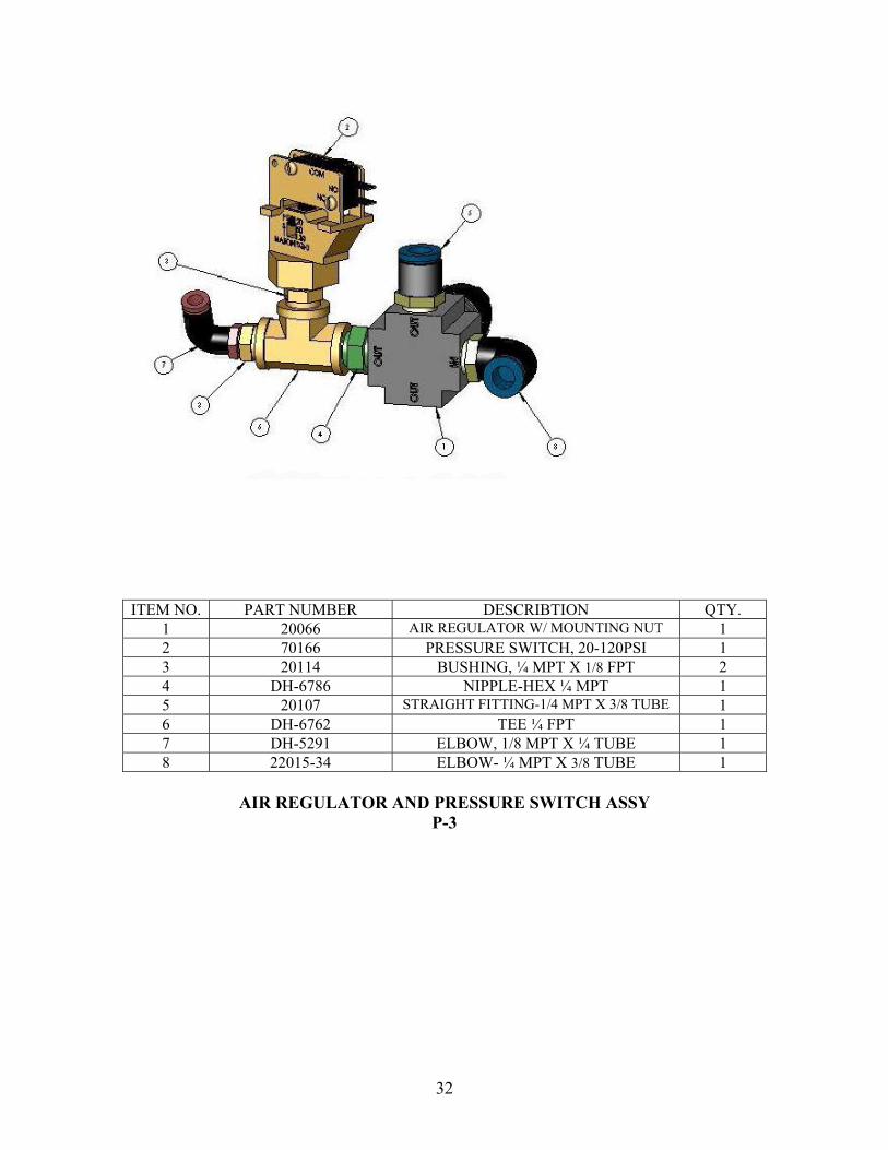
ITEM NO. PART NUMBER DESCRIBTION QTY.
1 20066 AIR REGULATOR W/ MOUNTING NUT 1 2 70166 PRESSURE SWITCH, 20-120PSI 1 3 20114 BUSHING, ¼ MPT X 1/8 FPT 2 4 DH-6786 NIPPLE-HEX ¼ MPT 1 5 20107 STRAIGHT FITTING-1/4 MPT X 3/8 TUBE 1 6 DH-6762 TEE ¼ FPT 1 7 DH-5291 ELBOW, 1/8 MPT X ¼ TUBE 1 8 22015-34 ELBOW- ¼ MPT X 3/8 TUBE 1
AIR REGULATOR AND PRESSURE SWITCH ASSY
P-3
32

ITEM NO. PART NUMBER DESCRIBTION QTY. 1 21983 AIR GAUGE 1 2 20152 CONN-1/4 FPT X 1/8/FPT 1 3 DH-5291 ELBOW, 1/8 MPT X ¼ TUBE 1
AIR GUAGE ASSY, AV
33
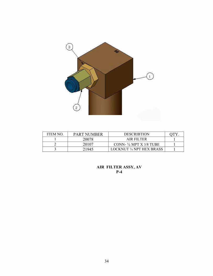
ITEM NO. PART NUMBER DESCRIBTION QTY.
1 20078 AIR FILTER 1 2 20107 CONN- ¼ MPT X 3/8 TUBE 1 3 21945 LOCKNUT ¼ NPT HEX BRASS 1
AIR FILTER ASSY, AV P-4
34
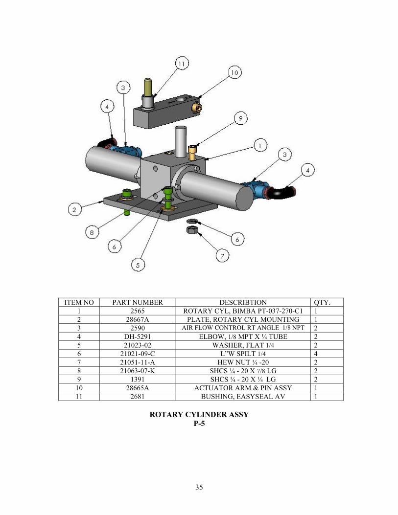
ITEM NO PART NUMBER DESCRIBTION QTY. 1 2565 ROTARY CYL, BIMBA PT-037-270-C1 1 2 28667A PLATE, ROTARY CYL MOUNTING 1 3 2590 AIR FLOW CONTROL RT ANGLE 1/8 NPT 2 4 DH-5291 ELBOW, 1/8 MPT X ¼ TUBE 2 5 21023-02 WASHER, FLAT 1/4 2 6 21021-09-C L”W SPILT 1/4 4 7 21051-11-A HEW NUT ¼ -20 2 8 21063-07-K SHCS ¼ - 20 X 7/8 LG 2 9 1391 SHCS ¼ - 20 X ¼ LG 2
10 28665A ACTUATOR ARM & PIN ASSY 1 11 2681 BUSHING, EASYSEAL AV 1
ROTARY CYLINDER ASSY
P-5
35

ITEM NO. PART NUMBER DESCRIBTION QTY.
1 2567 AIR VALVE 1 2 2568 PNEUMADYNE ADAPTOR 1 3 2566 BLACK BUTTON 1 4 21936 STR FITT 1/8 MPT X 5/32 TUBE 1 5 21934 ELBOW, 1/8 MPT X 5/32 TUBE 1
MANUAL AIR VALVE ASSY
ITEM NO. PART NUMBER DESCRIBTION QTY.
1 2327 AIR VALVE 1/8 PORTS 1 2 DH-5291 ELBOW, 1/8 MPT 3 3 71142 EXAUST MUFFLER P-18 2 4 21934 ELBOW, 1/8 MPT 2
AIR VALVE ASSY, ROTARY CYL
P-6
36
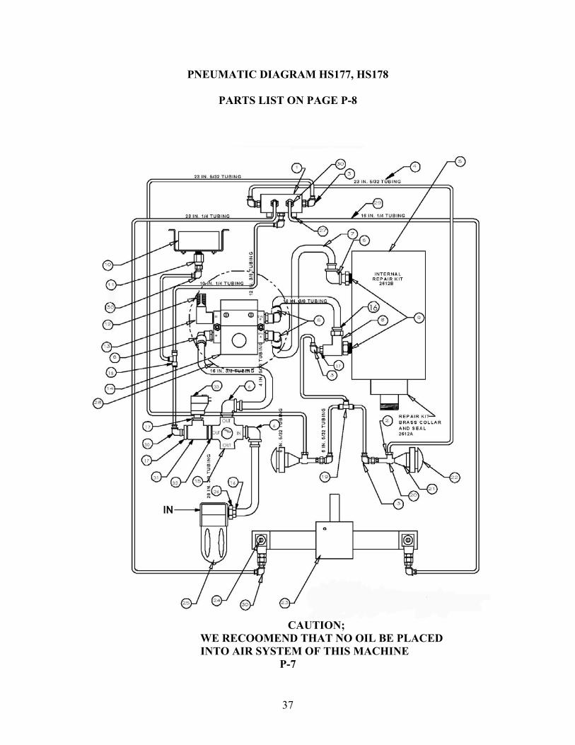
PNEUMATIC DIAGRAM HS177, HS178
PARTS LIST ON PAGE P-8
CAUTION;
WE RECOOMEND THAT NO OIL BE PLACED INTO AIR SYSTEM OF THIS MACHINE
P-7
37

PNEUMATIC DIAGRAM HS177, HS178 PARTS LIST FOR P-7
ITEM DESCRIBTION QTY PART NUMBER
1 AIR VALVE 1/8 FPT PORTS 1 2327 2 STRAIGHT FITTING 1/8 MPT X 5/32 TUBE 2 21936 3 ELBOW FITTING 1/8 MPT X 5/32 TUBE 5 21934 4 5/32” TUBING 68” 1871 5 BIMBA AIR CYLINDER 4” BORE, 3” STROKE 1 2845 6 ELBOW 3/8 TUBE ¼ MPT 6 22015-34 7 3/8 “TUBING 72” 9463 8 STREET TEE 1/4” NPT 1 20140 9 REDUCING BUSHING ½ MPT X ¼ MPT 2 9442
10 AIR PRESSURE GAUGE ¼ MPT 1 21983 11 REDUCING COUPLING ¼ FPT X 1/8 FPT 1 20152 12 SPEED CONTROL MUFFLER, ¼ MPT 1 2339 13 STREET ELBOW ¼ NPT 1 1598 14 AIR VALVE 1 2324 15 AIR REGULATOR W/MTG. NUT 1 20066 16 CONNECTOR 3/8” TUBE X ¼ MPT 2 20107 17 BRASS BUSHING ¼ NPT X 1/8 FPT 3 20114 18 INSTANT 3 WAY CONNECTOR ¼” TUBE 1 22025-17 19 FITTING, INSTANT TEE 5/32 1 21935 20 AIR VALVE 2 2567 21 PNEUMADYNE ADAPTOR 2 2568 22 BLACK BUTTON 2 2566 23 ROTARY CYLINDER 1 2565 24 FLOW CONTROL VALVE 1/8 NPT 2 2590 25 AIR FILTER 1 20078 26 HEX BRASS LOCK NUT ¼ NPT 1 21945 27 EXHAUST MUFFLER P-18 2 71142 28 AIR AVALVE ASSY. SEE NOTE 1 1 70152 29 1/4 “ TUBING, POLYFLO 64” DH-5297-1 30 ELBOW 1/8” MPT X ¼ “ TUBE 7 DH--5291 31 TEE, ¼ FPT 1 DH-6762 32 NIPPLE, HEX ¼ MPT 1 DH-6786 33 PRESSURE SWITCH, 20-120 PSI 7 70166
NOTE:
1. ITEM #28, AIR VALVE ASSEMBLY (70152) INCLUDES 6, 12, 13, & 14 P-8
38
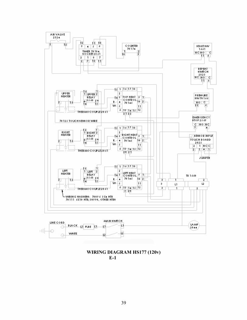
WIRING DIAGRAM HS177 (120v) E-1
39
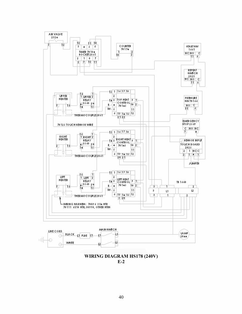
WIRING DIAGRAM HS178 (240V)
E-2
40
41
42

43
44