objet30 3d printer systems - cnsi microfluidics labmicrofluidics.cnsi.ucsb.edu/tools/objet 30 pro...
TRANSCRIPT
User GuideEnglish
Objet303D Printer Systems

DOC-34015 Rev. B
CopyrightCopyright © 2014 Stratasys Ltd. All rights reserved. This documentation contains proprietary information of Stratasys Ltd. This information is supplied solely to assist authorized users of Objet30 3D printing systems. No part of this document may be used for other purposes, and it may not be disclosed to other parties. The specifications on which this document is based are subject to change without notice.No part of this book may be reproduced in any form or by any means, nor stored in a database or retrieval system, without prior permission in writing from Stratasys Ltd.If this document is distributed as a PDF file, you may print it for internal use.
TrademarksThe following are registered trademarks of Stratasys Ltd.: Stratasys®, Objet®, FullCure®.The following are trademarks of Stratasys Ltd.: Objet30, Objet30‐Pro, Objet30‐OrthoDesk, Objet24, PolyJet, Objet Studio, Job Manager.Microsoft and Microsoft XP are trademarks of Microsoft Corporation.All names of products and services cited in this book are trademarks or registered trademarks of their respective companies.
FCC ComplianceThe equipment referred to in this guide has been tested and found to comply with the limits for a Class A device pursuant to part 15 of the FCC rules. These limits provide reasonable protection against harmful interference when the equipment is operated in a commercial environment. Objet 3D printing systems generate, use and can radiate radio‐frequency energy and, if not installed and used in accordance with the instruction manual, may cause harmful interference to radio communications. Operation of this equipment in a residential area is likely to cause harmful interference, in which case the user will be required to correct the interference at his own expense. The 3D printer referred to in this guide contains a transmitter module, FCC ID YH6‐RFID. NOTE: Stratasys is not responsible for radio or TV interference caused by unauthorized modification to this equipment. Such modification could void the user’s authority to operate the equipment.
Equipment RecyclingIn the European Union, this symbol indicates that when the last user wishes to discard a product, it must be sent to appropriate facilities for recovery and recycling. For information about proper disposal, check your purchase contract, or contact the supplier of the equipment.
Limitation of LiabilityThe product, software or services are being provided on an “as is” and “as available” basis. Except as may be stated specifically in your contract, Stratasys Ltd. expressly disclaims all warranties of any kind, whether express or implied, including, but not limited to, any implied warranties of merchantability, fitness for a particular purpose and non‐infringement.You understand and agree that Stratasys Ltd. shall not be liable for any direct, indirect, incidental, special, consequential or exemplary damages, including but not limited to, damages for loss of profits, goodwill, use, data or other intangible losses (even if Stratasys has been advised of the possibility of such damages), resulting from: (i) the use or the inability to use the product or software; (ii) the cost of procurement of substitute goods and services resulting from any products, goods, data, software, information or services purchased; (iii) unauthorized access to or alteration of your products, software or data; (iv) statements or conduct of any third party; (v) any other matter relating to the product, software, or services. The text and drawings herein are for illustration and reference only. The specifications on which they are based are subject to change. Stratasys Ltd. may, at any time and without notice, make changes to this document. Stratasys Ltd., for itself and on behalf of its subsidiaries, assumes no liability for technical or editorial errors or omissions made herein, and shall not be liable for incidental, consequential, indirect, or special damages, including, without limitation, loss of use, loss or alteration of data, delays, or lost profits or savings arising from the use of this document.

iv
PatentsThis product is covered by one or more of the following U.S. patents:5,386,5006,259,9626,569,3736,658,3146,850,3347,183,3357,209,7977,225,0457,364,6867,369,9157,479,5107,500,8467,604,7687,628,8577,658,9767,725,209
Stratasys Ltd. http://www.stratasys.com
DOC‐34015Revision BMarch 2014
DOC-34015 Rev. B
1 About This GuideUsing This Guide ............................................................................................................................... 1–2For More Information........................................................................................................................ 1–2Terms Used in This Guide................................................................................................................ 1–3
2 SafetySafety Features ................................................................................................................................... 2–3Symbols and Warning Labels .......................................................................................................... 2–4Safety Guidelines ............................................................................................................................... 2–5
Printer Installation .............................................................................................................................. 2–5Printer Operation ................................................................................................................................ 2–5UV Radiation ....................................................................................................................................... 2–5Printer Maintenance ........................................................................................................................... 2–5Model and Support Materials ........................................................................................................... 2–6
First Aid for Working with Printing Materials.............................................................................. 2–7Contact with Skin................................................................................................................................ 2–7Contact with Eyes ............................................................................................................................... 2–7Ingestion............................................................................................................................................... 2–7Inhalation ............................................................................................................................................. 2–7
Waste Disposal ................................................................................................................................... 2–8
3 Introducing the Objet 3D Printing SystemWork Configurations......................................................................................................................... 3–2Source Files ......................................................................................................................................... 3–4
STL Files ............................................................................................................................................... 3–4SLC Files............................................................................................................................................... 3–4
Printing Materials .............................................................................................................................. 3–5Available Materials............................................................................................................................. 3–5Storage .................................................................................................................................................. 3–7Shelf Life............................................................................................................................................... 3–7Exposure to Light................................................................................................................................ 3–7Safety Considerations......................................................................................................................... 3–7Disposal ................................................................................................................................................ 3–7
Work Environment ............................................................................................................................ 3–8Workstation Requirements............................................................................................................... 3–9Preparing Files for Use with Objet 3D Printing Systems........................................................... 3–10
Converting CAD Files to STL Format............................................................................................ 3–10Converting CAD Files to SLC Format ........................................................................................... 3–10
Objet Studio Software ..................................................................................................................... 3–11
4 Installing Objet SoftwareHow to Install Software for the Objet 3D Printing System.......................................................... 4–2How to Uninstall Objet Studio......................................................................................................... 4–6
Contents

Objet30 User Guide
vi
5 Using Objet StudioLaunching Objet Studio .................................................................................................................... 5–3
Windows® 7 Security Warning.........................................................................................................5–3Objet Studio Interface .........................................................................................................................5–4Ribbon Commands..............................................................................................................................5–6Objet Studio Commands Menu.........................................................................................................5–8Model Tree Pane ..................................................................................................................................5–8
Preparing Models for Production.................................................................................................... 5–9OBJDF Files: Overview.......................................................................................................................5–9Model Files ...........................................................................................................................................5–9Placing Objects on the Build Tray .....................................................................................................5–9Opening Objet Tray Files..................................................................................................................5–13Quick‐Access Model Commands....................................................................................................5–15Copying and Pasting Objects...........................................................................................................5–16Selecting Objects ................................................................................................................................5–17Surface Finish .....................................................................................................................................5–17
Positioning Objects on the Build Tray .......................................................................................... 5–18Automatic Orientation......................................................................................................................5–18Automatic Placement........................................................................................................................5–19Manual Positioning ...........................................................................................................................5–19
Model Orientation............................................................................................................................ 5–20Manipulating Objects on the Build Tray ...................................................................................... 5–21
Positioning Objects on the Z‐Axis...................................................................................................5–21Valid Object Placement.....................................................................................................................5–22Using a Grid to Position Objects .....................................................................................................5–23Measurement Units ...........................................................................................................................5–24Setting Model Dimensions ...............................................................................................................5–25Repositioning Objects .......................................................................................................................5–25Changing an Object’s Orientation...................................................................................................5–27Freezing Model Orientation.............................................................................................................5–28
Display Options................................................................................................................................ 5–29Viewing Objects .................................................................................................................................5–29Screen Layout.....................................................................................................................................5–31Tray Perspective ................................................................................................................................5–32Setting Object Colors.........................................................................................................................5–33Loading Large Files...........................................................................................................................5–34Large File Manipulation ...................................................................................................................5–34Zoom Options ....................................................................................................................................5–36
Handling Completed Trays............................................................................................................ 5–37Tray Validation ..................................................................................................................................5–37Production Estimates ........................................................................................................................5–38E‐mailing Objet Digital Files............................................................................................................5–38Printing the Tray File ........................................................................................................................5–39
Applying Additional Objet Studio Features ................................................................................ 5–40Dividing Objects ................................................................................................................................5–40Choosing the Support Strength .......................................................................................................5–41“Hollow”— Filling Models with Support Material......................................................................5–42Displaying the Cross Section of Objects.........................................................................................5–43Saving the Screen Display as an Image File ..................................................................................5–44Exporting and Importing Objet Build Trays .................................................................................5–45
Customizing Objet Studio............................................................................................................... 5–46Creating a Quick Access Toolbar ....................................................................................................5–46Hiding the Ribbon .............................................................................................................................5–47Display Colors....................................................................................................................................5–48Keyboard Shortcuts...........................................................................................................................5–49Setting User Preferences ...................................................................................................................5–50

User Guide
DOC-34015 Rev. B vii
Professional Mode Features ........................................................................................................... 5–51Default Settings ................................................................................................................................. 5–52Open GL Driver Configuration ...................................................................................................... 5–53
Getting Additional Objet Studio Assistance................................................................................ 5–55Objet Studio Version, Material Module and Licensed Features ............................................... 5–55Monitoring and Managing Print Jobs ........................................................................................... 5–57
Job Manager Screen .......................................................................................................................... 5–57Setting the Printer Connection........................................................................................................ 5–59Off‐line Mode .................................................................................................................................... 5–60Setting the Remote Printer Connection (Client Mode)................................................................ 5–62Job Manager Commands ................................................................................................................. 5–62Configuring User Alerts................................................................................................................... 5–65Printing the Tray ............................................................................................................................... 5–66Additional Server Features.............................................................................................................. 5–66
6 Operating & Maintaining the Objet30 3D PrinterStarting the Objet30 Printer .............................................................................................................. 6–2Loading Model and Support Cartridges ........................................................................................ 6–4Producing Models.............................................................................................................................. 6–6
Printer Interface Color Key................................................................................................................ 6–8Printing Indicators .............................................................................................................................. 6–9
Resuming Production After Printing has Stopped ..................................................................... 6–10Changing the Model Material ........................................................................................................ 6–12Keeping the Printer in Idle Mode.................................................................................................. 6–18Shutting Down the Printer ............................................................................................................. 6–19
Shutdown Wizard............................................................................................................................. 6–19Material Flush/Fill Wizard .............................................................................................................. 6–21
Maintaining the Printer................................................................................................................... 6–24Routine Maintenance Schedule....................................................................................................... 6–24Cleaning the Print Heads................................................................................................................. 6–25Pattern Test ........................................................................................................................................ 6–27Improving Print Quality .................................................................................................................. 6–28Cleaning and Replacing the Wiper ................................................................................................ 6–29Cleaning and Replacing the Roller Waste Collector.................................................................... 6–32Aligning the Print Heads................................................................................................................. 6–35Optimizing (Calibrating) Print Heads ........................................................................................... 6–39Replacing Print Heads...................................................................................................................... 6–46Testing and Calibrating the UV Lamp........................................................................................... 6–56Calibrating the Load Cells ............................................................................................................... 6–59Replacing the Odor Filter ................................................................................................................ 6–61Replacing the UV Lamp................................................................................................................... 6–62Built‐in Tests ...................................................................................................................................... 6–66Replacing the Waste Container....................................................................................................... 6–68Cleaning the Exterior Panels ........................................................................................................... 6–70Backing‐Up and Restoring Printer Settings .................................................................................. 6–70ReInitiate Wizard .............................................................................................................................. 6–70
7 Handling Printed ModelsRemoving Models After Printing .................................................................................................... 7–2Removing the Support Material ...................................................................................................... 7–2Post‐Printing Treatment for Models Printed with Objet VeroClear .......................................... 7–4
Photo‐Bleaching Instructions ............................................................................................................ 7–4Storing Models ................................................................................................................................... 7–5


DOC-34015 Rev. B 1–1
About This Guide
Using This Guide................................................................................. 2For More Information ......................................................................... 2Terms Used in This Guide.................................................................. 3

About This Guide
1–2 DOC-34015 Rev. B
Using This GuideThis user guide provides instructions for installing, operating and maintaining Objet 3D printing systems. It explains how to use features, and provides practical examples to guide you as you use the system.This document is meant to be used with Objet30 3D printers, running software version 33.2.0, and with Objet Studio software version 9.2.This guide assumes that:• all the hardware, software, and network components of your Objet
system are installed, configured, and operating correctly.• the operator has a working knowledge of the Windows® PC platform.
For More InformationVisit http://www.stratasys.com/ for more details about Objet printer technology, products and consumables, and for service and support contacts.For other documents that relate to Objet30 3D printing systems, and for this document in other languages, contact your regional Stratasys Customer Support office.If you have any questions about the information presented in this document, or if you have any comments or suggestions for future editions, please send a message to c‐[email protected].
DOC-34015 Rev. B 1–3
Objet30 User Guide
Terms Used in This Guide
build tray In Objet Studio: The surface displayed on the screen that represents the actual build tray in the printer.In the printer: The surface upon which models are produced.
cleaning fluid Cleanser for flushing material feed tubes and the printing block, used to completely remove Model and Support material from the system before loading another type of material in the printer and before long‐term shutdown. The cleaning fluid is supplied in standard material cartridges.
client/user workstation The workstation on which Objet software is installed, used for preparing build trays for production on Objet printers. (There is no limit to the number of client workstations in the local network.)
Objet™ printer The Objet 3D printer referred to in this guide.
Printer computer The computer inside the Objet printer that operates it. (This is sometimes referred to as the “embedded” computer.)
Printer interface The GUI (graphical user interface) used for controlling the Objet printer.
Printer software Software running on the computer inside the Objet printer, that controls all printer operations.
host/server workstation The workstation that interfaces directly with the Objet printer and is typically positioned next to it.
Job Manager™ The part of Objet Studio software that manages production jobs before they are sent to the Objet printer.
Model material Material used for building models.
Objet Studio™ The software with which users prepare jobs for producing models.
OBJTF (Objet Tray Format) The extension of a file that contains all of the information needed for a model‐printing job on Objet 3D printers. An objtf file is used to send a print job to an Objet 3D printer.
OBJZF (Objet Z Format) The extension of a compressed “wrapper” file containing all of the files used in an Objet Studio build tray. Using objzf files, a printing job can be saved as a single file, for convenient storage and transfer.
resin The base substance from which photopolymer printing materials are made for use in Objet printers. In Objet Studio and printer‐application screens, “resin” refers to cartridges of model and support materials.

About This Guide
1–4 DOC-34015 Rev. B
SLC A file type used with Objet software. (These files are bitmaps of individual slices of the object. For more information, see page 3‐4.)
STL A file type used with Objet software. (For more information, see page 3‐4.)
Support material Material used for supporting the structure of models during production.

DOC-34015 Rev. B 2–1
Safety
Safety Features............................................................................................. 3Symbols and Warning Labels .................................................................... 4Safety Guidelines......................................................................................... 5
Printer Installation ......................................................................................... 5Printer Operation ........................................................................................... 5UV Radiation .................................................................................................. 5Printer Maintenance ...................................................................................... 5Model and Support Materials ...................................................................... 6
First Aid for Working with Printing Materials ....................................... 7Waste Disposal............................................................................................. 8


DOC-34015 Rev. B 2–3
Objet30 User Guide
Safety FeaturesObjet 3D printers are designed to comply with CE and FCC standards. They are equipped with the following safety features:
Figure 2-1: Front and back views of the Objet30 printer
Cover Interlock Switch
The power supplied to the UV lamp and the motion motors is turned off when the cover is opened.WARNING: Do not defeat (override) the interlock switch. Doing so could result in serious personal injury. If the interlock switch does not function correctly, do not use the printer, and contact your service provider.
Safety Lock The cover is locked while the printer is working. The lock is released when the printer reverts to pause or stop mode.WARNING: Do not defeat (override) the safety lock. Doing so could result in serious personal injury. If the safety lock does not function correctly, do not use the printer, and contact your service provider.
UV Screening The transparent section of the cover blocks harmful UV radiation, allowing the operator to view the model as it is being made.
Circuit Breaker The power to the printer is turned off in case of electrical overcurrent. Note: The circuit breaker is only accessible to service personnel.
Grounded Chassis The chassis of the printer is grounded, to prevent electrical shock.Note: The power outlet must be properly grounded, in accordance with the local electric code, to provide this protection.
UV screen
Cover interlock switch
Circuit breaker
If the Objet 3D printing system is not used as specified in this guide, the safety features may not provide adequate protection.

Safety
2–4 DOC-34015 Rev. B
Symbols and Warning LabelsThis following table lists the warning labels located on or in Objet printers.
Warning Symbol
Meaning Location Comments
Hazard (general)
On the name plate on the back of the printer.
Read the instructions in this document before operating the printer.
Hot surface On the print‐head block.
Risk of burns. Do not touch this surface after printing.
High voltage Near the UV lamp connector.Near the power‐supply enclosures.
Risk of electric shock.
Ultraviolet radiation
Near the UV lamp. Risk of injury from ultraviolet radiation.
Moving parts On top of the printing assembly.
Risk of injury from moving parts.

DOC-34015 Rev. B 2–5
Objet30 User Guide
Safety GuidelinesThe following general guidelines, together with the instructions provided throughout this user guide, ensure user safety while operating and maintaining the Objet system. If the system is not operated as specified, the userʹs safety may be compromised!
Printer Installation
Installation and removal of the printer should only be done by qualified service personnel. Connect the printer to the electric outlet using a power cord that is safety‐certified.The electric outlet should be easily accessible, near the printer.Never connect the power plug to an outlet that does not have a ground (earth) wire, and never disconnect the ground. Doing so might expose the operator to serious danger from electric shock.
FI: Laite on liitettävä suojakoskettimilla varustettuun pistorasiaan.NO: Apparatet må tilkoples jordet stikkontakt.SE: Apparaten skall anslutas till jordat uttag.
Leave a minimum of 20 centimeters between ventilation openings and walls or other objects.
Printer Operation
The printer should only be operated by persons trained by a Stratasys customer‐support representative.All personnel operating or maintaining the printer should know the location of first aid and emergency equipment and how to use it. Never block access to this equipment!Keep fingers and other body parts clear of the printer cover when closing it.Never attempt to open the main cover of the printer while it is working!Never override the interlock safety switch!If the interlock safety switch ever fails, do not use the printer. Several parts of the printer remain extremely hot even after it has stopped operating. Avoid touching the UV lamp and the print block.
UV Radiation The UV lamp used in the printer emits dangerous radiation. If the UV lamp remains on when the printer cover is open, do not stare directly at the UV light. Shut down the printer and call your Stratasys service provider.
Printer Maintenance
Service operations should be performed only by qualified personnel who have been instructed in relevant safety precautions.Notify co‐workers and those who have access to the Objet system before beginning non‐routine and hazardous work.
Report any potential dangers and safety-related accidents to your safety officer or to other appropriate authorities.

Safety
2–6 DOC-34015 Rev. B
Model and Support Materials
Model and support materials are made of chemical substances. Although precautions must be taken when handling these materials directly, all model and support materials used by the Objet system are handled in sealed cartridges. Normally, operators of the printer should never be directly exposed to hazardous materials. In the unlikely event of a leak or spill, follow the instructions that are included with the printing‐material cartridge used.
Store model and support materials indoors, in a dry area with adequate ventilation, between 16‐27 degrees Celsius (60‐81 degrees Fahrenheit). Never expose them to flames, heat, sparks, or direct sunlight.Keep model and support materials away from areas where food and drink are stored, prepared and consumed.Uncured printing material is considered a hazardous substance, requiring certain precautions when directly handling it. To prevent skin irritation, wear neoprene or nitrile gloves. If there is any chance that model and support materials might splash into the eyes, wear safety goggles. Prolonged direct contact with printing materials can cause an allergic reaction.When handling UV‐cured models that may not be completely cured on the surface, common latex gloves are adequate. To prevent respiratory irritation, ventilate areas where model and support materials are used. The ventilation system should totally replace the air at least four times per hour.Clean up model‐material and support‐material spills with disposable towels or other absorbent, non‐reusable material, such as sawdust or activated charcoal. Rinse the spill area with denatured or isopropyl alcohol (IPA), followed by soap and water. Dispose of the absorbent material in accordance with local regulations.Do not wash contaminated clothing at home; clothing should be professionally laundered.Dispose of contaminated shoes, belts and other leather items in accordance with any applicable regulations. Absorbed printing material may re‐expose the user when these items are worn.

DOC-34015 Rev. B 2–7
Objet30 User Guide
First Aid for Working with Printing MaterialsIn general, try to avoid direct contact with uncured printing material. If skin or eyes come into contact with it, wash the area immediately and thoroughly with water, and follow these first‐aid instructions.
Contact with Skin
If uncured printing material comes in contact with skin, wash the affected area immediately and thoroughly with soap and cool water, then remove contaminated clothing. Pay particular attention to flushing the hair, ears, nose and other parts of the body that are not easily cleaned.
Use cool water to prevent skin pores from opening, so that the liquid material does not easily penetrate the skin. Do not use solvents to clean skin. If large areas of skin have been exposed, or if prolonged contact results in blisters, seek medical attention. In any case, if irritation persists, seek medical attention.Avoid the accidental transfer of printing material from the hands to other areas of the body, especially to the eyes. If protective cream was used, do not reapply it until the skin has been completely cleansed.
Contact with Eyes
If uncured printing material comes in contact with the eyes, flush immediately with large amounts of water for 15 minutes and seek medical attention.
Avoid sunlight, fluorescent light, and other sources of ultraviolet radiation.
The wearing of contact lenses when handling liquid printing materials is not recommended. If the liquid splashes into the eyes when contact lenses are worn, immediately remove the lenses and flush the eyes with water.
Clean and disinfect the contaminated lenses.Do not wear contact lenses until eye irritation disappears.
Ingestion If printing material is swallowed, refer to the instructions included with the cartridge. Seek medical attention immediately.
Inhalation Vapors from printing materials can be irritating to the respiratory system. If respiratory irritation occurs, expose the victim to fresh air immediately.
If the victim has stopped breathing, perform artificial respiration or cardiopulmonary resuscitation. Seek medical attention immediately.Keep the patient warm but not hot. Never feed anything by mouth to an unconscious person.Oxygen should be administered by authorized personnel only.
The Material Safety Data Sheet (MSDS) that accompanies printing materials contains important safety information. Keep this in an accessible place where these materials are used and stored.

Safety
2–8 DOC-34015 Rev. B
Waste Disposal Fully cured printed models can be disposed of as ordinary office trash. However, special care is required when handling printer waste.
When removing the waste container from the Objet printer, wear neoprene or nitrile gloves.To prevent liquid waste from splashing into the eyes, wear safety goggles.Liquid waste from the Objet printer is classified as hazardous industrial waste. Therefore, printing‐material waste must be packaged and disposed of in a manner that prevents human contact with it and contamination of water sources.Empty model‐material and support‐material cartridges contain residue of their contents. Some leakage of this residue may occur through the broken cartridge seal. Therefore, handle and store empty cartridges with care. Do not attempt to reuse empty cartridges, and do not puncture them.Dispose of used cartridges and waste containers in accordance with local regulations.Discard contaminated clothing, shoes, empty containers, etc., in accordance with any applicable regulations.

DOC-34015 Rev. B 3–1
Introducing the Objet 3D Printing System
Work Configurations .................................................................................. 2Source Files................................................................................................... 4
STL Files .......................................................................................................... 4SLC Files .......................................................................................................... 4
Printing Materials........................................................................................ 5Available Materials ........................................................................................ 5Storage ............................................................................................................. 7Shelf Life .......................................................................................................... 7Exposure to Light ........................................................................................... 7Safety Considerations.................................................................................... 7Disposal ........................................................................................................... 7
Work Environment...................................................................................... 8Workstation Requirements ........................................................................ 9Preparing Files for Use with Objet 3D Printing Systems .................... 10
Converting CAD Files to STL Format ....................................................... 10Converting CAD Files to SLC Format....................................................... 10
Objet Studio Software ............................................................................... 11

Introducing the Objet 3D Printing System
3–2 DOC-34015 Rev. B
Figure 3-1: The Objet30 3D Printer
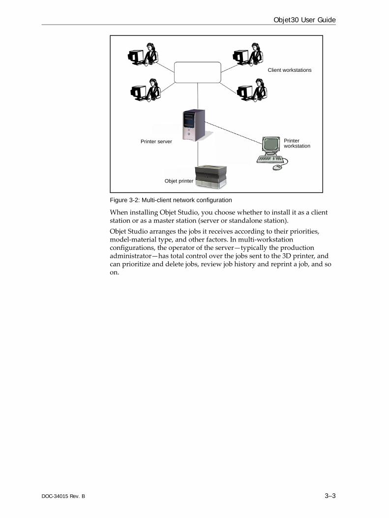
Work ConfigurationsThe Objet 3D printing system can be set up as a single‐station system or as a multi‐station system. When connected to a local computer network, the system can serve multiple users. In such configurations, each user workstation (client) prepares files with Objet Studio software for production. A server (host), typically next to the 3D printer, acts as a job manager that sends production jobs to the printer for production. Figure 3‐2 shows the Objet30 printer set up in a multi‐client configuration.
DOC-34015 Rev. B 3–3
Objet30 User Guide
Figure 3-2: Multi-client network configuration
When installing Objet Studio, you choose whether to install it as a client station or as a master station (server or standalone station).Objet Studio arranges the jobs it receives according to their priorities, model‐material type, and other factors. In multi‐workstation configurations, the operator of the server—typically the production administrator—has total control over the jobs sent to the 3D printer, and can prioritize and delete jobs, review job history and reprint a job, and so on.
Printer server
Client workstations
Printer workstation
Objet printer

Introducing the Objet 3D Printing System
3–4 DOC-34015 Rev. B
Source Files Objet 3D printing systems produce three‐dimensional models designed with most 3D CAD tools and with other job‐specific 3D applications. Objet systems accept:• STL Files• SLC FilesObjet systems feature the capability of producing different types of model files simultaneously.
STL Files STL is short for Standard Triangulation Language. This language views any object as a collection of surfaces, and describes each surface of the object as a collection of triangles. For example, a square can be described as two triangles; a cube (six squares) as 12 triangles. Curved surfaces need more triangles to describe them. The higher the tolerance (for smooth surfaces), the more triangles are needed. The result is that high‐quality object descriptions mean very heavy files. Most CAD software can export STL files. The Objet system utilizes these files for building models (rapid prototyping), and also for directly making molds for mass‐producing items.STL files can be ASCII (text) files or binary files. The content of the ASCII file begins with “solid” and ends with “end‐solid” (both lower case). Between these keywords is a list of the triangles that describes the faces of the solid model. Each triangle defines a single normal vector directed away from the solid’s surface, followed by its X‐Y‐Z coordinates. These are expressed as Cartesian coordinates and are floating‐point values. The coordinates of all triangles should be positive and should fall within the volume of the model.
SLC Files SLC is short for Stereo‐Lithography Contour. SLC files describe two‐dimensional contours of the three‐dimensional models. These contour lines are polylines. SLC files are ASCII (text) files that save models as a series of slices. This means that models based on SLC files cannot be orientated; only their scale (size) and position on the build tray can be controlled. For this reason, the model’s orientation must be suitable for production before it is saved as an SLC file. Because of the nature of SLC files, the appearance of models in Objet Studio may be different than the solid‐object images displayed from STL files.
DOC-34015 Rev. B 3–5
Objet30 User Guide
Printing MaterialsObjet printers produce models by jetting thin layers of printing materials on the build tray, until the complete model is formed. Two types of material are used in this process:• Model material—which makes up the finished model• Support material—which fills gaps and spaces in the model during
printing, and is removed after printing
Available Materials
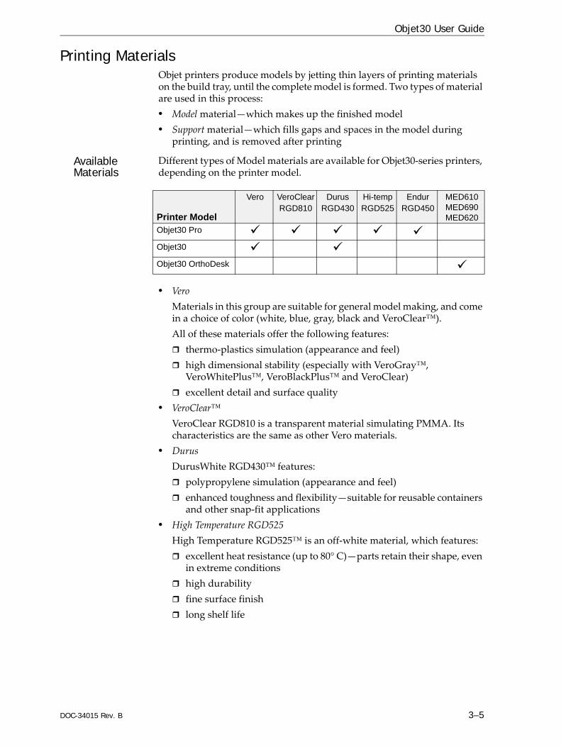
Different types of Model materials are available for Objet30‐series printers, depending on the printer model.
• Vero Materials in this group are suitable for general model making, and come in a choice of color (white, blue, gray, black and VeroClear™).All of these materials offer the following features:
thermo‐plastics simulation (appearance and feel)high dimensional stability (especially with VeroGray™, VeroWhitePlus™, VeroBlackPlus™ and VeroClear)excellent detail and surface quality
• VeroClear™VeroClear RGD810 is a transparent material simulating PMMA. Its characteristics are the same as other Vero materials.
• DurusDurusWhite RGD430™ features:
polypropylene simulation (appearance and feel)enhanced toughness and flexibility—suitable for reusable containers and other snap‐fit applications
• High Temperature RGD525High Temperature RGD525™ is an off‐white material, which features:
excellent heat resistance (up to 80° C)—parts retain their shape, even in extreme conditionshigh durabilityfine surface finishlong shelf life
Printer Model
Vero VeroClearRGD810
DurusRGD430
Hi-tempRGD525
EndurRGD450
MED610 MED690 MED620
Objet30 Pro
Objet30
Objet30 OrthoDesk

Introducing the Objet 3D Printing System
3–6 DOC-34015 Rev. B
• Endur RGD450Endur RGD450™ is a white material, which features:
polypropylene simulation (appearance and feel)enhanced toughnesshigh dimensional stabilityexcellent detail and surface quality
• MEDMaterials with Vero‐material properties, formulated for medical and dental applications.
MED610™—clear, bio‐compatibleVeroGlaze MED620™—whiteVeroDentPlus MED690™—opaque, peach color
For up-to-date information about PolyJet printing materials and their properties, go to http://www.stratasys.com/materials/polyjet.

DOC-34015 Rev. B 3–7
Objet30 User Guide
Storage Materials used for printing models with Objet printers are made of resins, which are composed of reactive monomers and oligomers. Although printing materials are supplied in sealed, UV‐proof cartridges, care must be taken when storing and handling them. Follow these guidelines to protect operators and the environment, and to ensure optimum results. • To ensure product stability, do not allow these materials to come into
contact with metal. Plastics made from monomer‐soluble substances (such as polystyrene or polyvinyl chloride) are not suitable for storing PolyJet printing materials.
• When not in use, keep material cartridges tightly sealed to prevent contamination, the effects of exposure to UV radiation, and accidental spillage.
• Store material cartridges indoors, in a dry area with adequate ventilation, between 16–27 degrees Celsius (60–81 degrees Fahrenheit). If exposed to heat or flames, cartridges may burst or ignite.
• Signs of premature polymerization in material cartridges may include bulging, leaking, the emission of heat, and unusual odor. Exposure to heat can cause resin to gel in the cartridge.
• Make sure that material cartridges are stored in accordance with all local regulations and other applicable requirements.
Shelf Life Materials used for producing models have a limited shelf life. The expiry date on the label is valid when properly stored in an undamaged, unopened cartridge. Always rotate your stock, so that the cartridge with the earliest date is used first.
Exposure to Light
If printing materials are not in their sealed cartridges, make sure to shield them from sunlight and other sources of UV radiation, such as fluorescent and mercury‐vapor lights. Exposure to UV radiation causes an increase in viscosity and, eventually, solidification.
Safety Considerations
Before being cured, resins are hazardous materials. To prevent possible health hazards, follow these precautions regarding printing materials: • Do not expose to flames, heat or sparks.• Prevent contact with skin and eyes.• Ventilate areas where they are handled. • Keep them separate from food and drink.Cured plastic parts, however, are safe. They can be handled and stored without precautions.
Disposal Dispose of cartridges of model and support material in accordance with all applicable laws and regulations. If necessary, the cartridges can be disassembled for recycling.
You can find more safety information about resins in “Safety Guidelines” on page 2-5, and “First Aid for Working with Printing Materials” on page 2-7.

Introducing the Objet 3D Printing System
3–8 DOC-34015 Rev. B
Work EnvironmentExtreme heat and humidity conditions can adversely affect the operation of the Objet 3D printer. Therefore, it is recommended that you use ventilation or air‐conditioning systems, if necessary, to keep the work area within the following ranges:• 18°–25° C (64°–77° F)• 30%–70% relative humidity

DOC-34015 Rev. B 3–9
Objet30 User Guide
Workstation Requirements The table below lists the requirements for computer components on workstations running Objet Studio.Important: Make sure that the server workstation is set up with Administrator privileges.
Requirement
Computer Type Server workstation: Standard desktop PC1
Processor Intel® Core™ i3 or better
Operating System Windows® 7 or Windows® 8, 64-bit2
RAM 8 GB or more2
Graphics Card3Open GL® Memory: 1 GB; 2 GB recommended for dental applications
For server workstation: VGA connector4
Optical Drive CD/DVD ROM
Hard-Disk Drive 80 GB or larger (minimum free space: 40 GB)
Network Card LAN TCP/IP (2 for server workstation; 1 for client workstation)
Mouse/Keyboard Connection Server workstation: USB1
Monitor Cable VGA connector1
1. For systems using a KVM switchbox to control both the built‐in printer computer and the server workstation with same keyboard‐monitor‐mouse set: All‐in‐one computer, wireless mouse and wireless keyboard cannot be used.
2. A 64‐bit operating system is recommended, to utilize 8 GB of memory. Objet Studio running on a 32‐bit application can utilize only 4 GB of memory.
3. The following graphics cards were tested in Stratasys labs:• NVIDIA® Quadro® Family—FX570, FX1700• NVIDIA® GeForce® Family—6200 TurboCache™, 7300 GT, GTX 285• Intel® Express Chipset—82915G/GV, 82910GL, Q965, Q963, Q35, Q45, Q43, 82852, 82855
• ATI Radeon™ HD 5670, HD 5970• AMD Radeon™ E6760
4. For systems using a KVM switchbox. If the server workstation has a DVI video connector, a VGA adapter is needed.

Introducing the Objet 3D Printing System
3–10 DOC-34015 Rev. B
Preparing Files for Use with Objet 3D Printing SystemsBefore using files with Objet 3D printing systems, you need to convert them in your CAD program to a file format supported by Objet Studio. (For an explanation of these file formats, see “Source Files” on page 3‐4.)You can print several models or parts at the same time, after arranging them on the build tray in Objet Studio. The following are the maximum dimensions for a single model printed on the Objet30 printer:• With glossy finish—
X‐axis: 294.00 mm (11.57 inches)Y‐axis: 192.00 mm (7.55 inches)Z‐axis: 148.60 mm (5.85 inches)*
* OrthoDesk printers—100.0 mm (3.94 inches)• With matte finish—
X‐axis: 293.00 mm (11.53 inches)Y‐axis: 191.00 mm (7.52 inches)Z‐axis: 148.30 mm (5.83 inches)*
* OrthoDesk printers—97.9 mm (3.85 inches)
Converting CAD Files to STL Format
This procedure may vary slightly, depending on the CAD software used, but the following instructions generally apply.
To convert a file to STL format (in a CAD program):1. From the File menu, select Save As.2. In the Save As dialog box, open the Save As Type pull‐down menu and
select *.STL.3. Click Options and set the following parameters:
• Total Quality—approximately 0.01 mm (deviation tolerance / linear‐dimension tolerance)
• Detail Quality—approximately 5° (angle tolerance)Note: Lowering these values produces more accurate models, but results in larger files and longer loading and processing times. For this reason, it is generally not recommended that you use lower values.
4. In the file format option, choose binary or ASCII. (Both binary and ASCII formats can be used in Objet Studio. However, binary files are smaller, so this option is recommended.)
5. Click OK or Save.After converting the model files, it is recommended that you check them for defects in an STL‐repair application (such as Magics™, by Materialise®) before opening them in Objet Studio and producing the model.
Converting CAD Files to SLC Format
When converting files to SLC format, it is recommended that you set a layer thickness of 15 microns (0.015 mm). Since SLC files cannot be orientated in Objet Studio, it is important that models are properly orientated before being saved as SLC files. Considerations for suitable model orientation are explained in “Model Orientation” on page 5‐20.

DOC-34015 Rev. B 3–11
Objet30 User Guide
Objet Studio SoftwareObjet Studio software for the Objet 3D printing system consists of two main screens:• Tray Settings / Model Settings• Job Manager
Tray Settings / Model SettingsIn the Tray Settings and Model Settings screens, you prepare source files for production in Objet 3D printers. Objet Studio offers you a wide variety of file‐preparation options, but always consists of the following basic procedure:1. Inserting one or more objects on the build tray2. Positioning the object(s) on the tray3. Configuring object and tray parameters4. Saving the tray configuration as an objtf (Objet Tray Format) file5. Sending the objtf file to the Objet 3D printer for productionUsing Objet Studio to perform these tasks is described in detail in chapter 5, “Using Objet Studio.”
Job ManagerThe Job Manager screen is different for client workstations and for the computer connected directly to the Objet 3D printer. • In Objet Studio installed on the directly‐connected computer (server),
the Job Manager screen displays the queue and status for all jobs sent to the 3D printer by the server itself and by all client computers on the network. All jobs displayed can be edited and manipulated.
• In Objet Studio installed on client computers, the Job Manager screen displays the queue and status only for jobs sent to a 3D printer server from that computer. Only these jobs can be edited and manipulated from the client computer.
Client computers can be connected, via the local network, to different Objet 3D printers, but only to one at a time. The Job Manager screen displays the status of the 3D printer to which the client is currently connected.


DOC-34015 Rev. B 4–1
Installing Objet Software
How to Install Software for the Objet 3D Printing System ........... 2
Installing Objet Software
4–2 DOC-34015 Rev. B
How to Install Software for the Objet 3D Printing SystemThe Objet Studio setup wizard guides you when installing this software. Objet Studio is installed on the printer‐server (“host”) computer, but it can also be installed on remote, “client” computers and on computers used to prepare files for printing models, or for training and demonstration purposes. During installation, you choose to install either the printer‐server (“host”) application or the client application.
To install Objet software:1. Insert the Objet Studio CD into the disk drive.2. Right‐click the Start button and select Explore (or use any other method
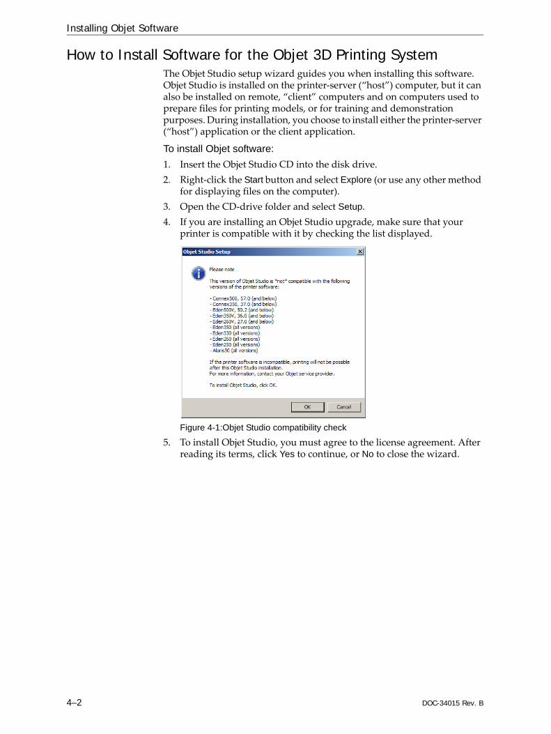
for displaying files on the computer).3. Open the CD‐drive folder and select Setup.4. If you are installing an Objet Studio upgrade, make sure that your
printer is compatible with it by checking the list displayed.
Figure 4-1:Objet Studio compatibility check
5. To install Objet Studio, you must agree to the license agreement. After reading its terms, click Yes to continue, or No to close the wizard.
DOC-34015 Rev. B 4–3
Objet30 User Guide
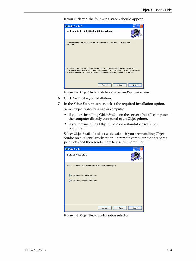
If you click Yes, the following screen should appear.
Figure 4-2: Objet Studio installation wizard—Welcome screen
6. Click Next to begin installation.7. In the Select Features screen, select the required installation option.
Select Objet Studio for a server computer...• if you are installing Objet Studio on the server (“host”) computer—
the computer directly connected to an Objet printer.• if you are installing Objet Studio on a standalone (off‐line)
computer.Select Objet Studio for client workstations if you are installing Objet Studio on a “client” workstation—a remote computer that prepares print jobs and then sends them to a server computer.
Figure 4-3: Objet Studio configuration selection
Installing Objet Software
4–4 DOC-34015 Rev. B
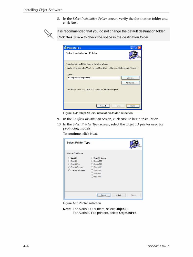
8. In the Select Installation Folder screen, verify the destination folder and click Next.
Figure 4-4: Objet Studio installation-folder selection
9. In the Confirm Installation screen, click Next to begin installation. 10. In the Select Printer Type screen, select the Objet 3D printer used for
producing models. To continue, click Next.
Figure 4-5: Printer selection
Note: For Alaris30U printers, select Objet30.For Alaris30 Pro printers, select Objet30Pro.
It is recommended that you do not change the default destination folder.
Click Disk Space to check the space in the destination folder.

DOC-34015 Rev. B 4–5
Objet30 User Guide
Installation begins and a progress bar appears, showing the progress of the installation process.
Figure 4-6: Installation progress bar
When the Objet program installation is complete, the final InstallShield Wizard screen appears.
Figure 4-7: Final installation screen
11. Restart the computer to complete the software installation.
Note: If you installed the software from a CD or DVD, make sure to remove it from the disk drive before restarting the computer.
The installation process ends when the appropriate icon(s) appear on the computer desktop: • Objet Studio• Stop Job Manager (for servers and standalone stations)

Installing Objet Software
4–6 DOC-34015 Rev. B
How to Uninstall Objet StudioIf there is ever a need to uninstall the Objet Studio software, do not attempt to do so from the Windows Control Panel. (This does not completely remove all software components.) Instead—
From the Start menu, select All Programs > Objet Studio > Uninstall Objet Studio.

DOC-34015 Rev. B 5–1
Using Objet Studio
Launching Objet Studio...................................................................... 3Windows® 7 Security Warning........................................................... 3Objet Studio Interface ........................................................................... 4Ribbon Commands ............................................................................... 6Objet Studio Commands Menu .......................................................... 8Model Tree Pane .................................................................................... 8
Preparing Models for Production ..................................................... 9OBJDF Files: Overview......................................................................... 9Model Files ............................................................................................. 9Placing Objects on the Build Tray....................................................... 9Opening Objet Tray Files ................................................................... 13Quick‐Access Model Commands...................................................... 15Copying and Pasting Objects ............................................................ 16Selecting Objects.................................................................................. 17Surface Finish....................................................................................... 17
Positioning Objects on the Build Tray ............................................ 18Automatic Orientation ....................................................................... 18Automatic Placement ......................................................................... 19Manual Positioning............................................................................. 19
Model Orientation............................................................................. 20Manipulating Objects on the Build Tray........................................ 21
Positioning Objects on the Z‐Axis .................................................... 21Valid Object Placement....................................................................... 22Using a Grid to Position Objects ....................................................... 23Measurement Units............................................................................. 24Setting Model Dimensions................................................................. 25Repositioning Objects......................................................................... 25Changing an Object’s Orientation..................................................... 27Freezing Model Orientation .............................................................. 28
Display Options................................................................................. 29Viewing Objects................................................................................... 29Screen Layout ...................................................................................... 31Tray Perspective .................................................................................. 32Setting Object Colors .......................................................................... 33Loading Large Files ............................................................................ 34Large File Manipulation..................................................................... 34Zoom Options...................................................................................... 36
Handling Completed Trays ............................................................. 37Tray Validation .................................................................................... 37Production Estimates.......................................................................... 38E‐mailing Objet Digital Files ............................................................. 38Printing the Tray File .......................................................................... 39

5–2 DOC-34015 Rev. B
Applying Additional Objet Studio Features ................................. 40Dividing Objects.................................................................................. 40Choosing the Support Strength......................................................... 41“Hollow”— Filling Models with Support Material ....................... 42Displaying the Cross Section of Objects .......................................... 43Saving the Screen Display as an Image File .................................... 44Exporting and Importing Objet Build Trays ................................... 45
Customizing Objet Studio................................................................ 46Creating a Quick Access Toolbar ...................................................... 46Hiding the Ribbon............................................................................... 47Display Colors ..................................................................................... 48Keyboard Shortcuts ............................................................................ 49Setting User Preferences..................................................................... 50
Professional Mode Features............................................................. 51Default Settings ................................................................................... 52Open GL Driver Configuration......................................................... 53
Getting Additional Objet Studio Assistance ................................. 55Objet Studio Version, Material Module and Licensed Features. 55Monitoring and Managing Print Jobs ............................................ 57
Job Manager Screen ............................................................................ 57Setting the Printer Connection .......................................................... 59Off‐line Mode....................................................................................... 60Setting the Remote Printer Connection (Client Mode).................. 62Job Manager Commands ................................................................... 62Configuring User Alerts..................................................................... 65Printing the Tray.................................................................................. 66Additional Server Features ................................................................ 66

DOC-34015 Rev. B 5–3
Objet30 User Guide
Launching Objet StudioAfter you install Objet Studio, a launch icon appears on the Windows desktop. Open the application by double‐clicking this icon, or by selecting Objet Studio from the Start menu.
Windows® 7 Security Warning
Depending on the User Account Control settings in Windows® 7, you may see the following warning when opening Objet Studio.
Figure 5-1: Security Warning
If you click Yes, Objet Studio opens. However, this warning message will appear each time you open the program, unless you change the User Account Control settings.
To prevent the warning message from appearing again:1. Click the link at the bottom of the security warning dialog box (Change
when these notifications appear).2. In the User Account Control Settings screen, move the slider to “Never
notify.”
Figure 5-2: Changing the User Account Control settings
3. Click OK.
Using Objet Studio
5–4 DOC-34015 Rev. B
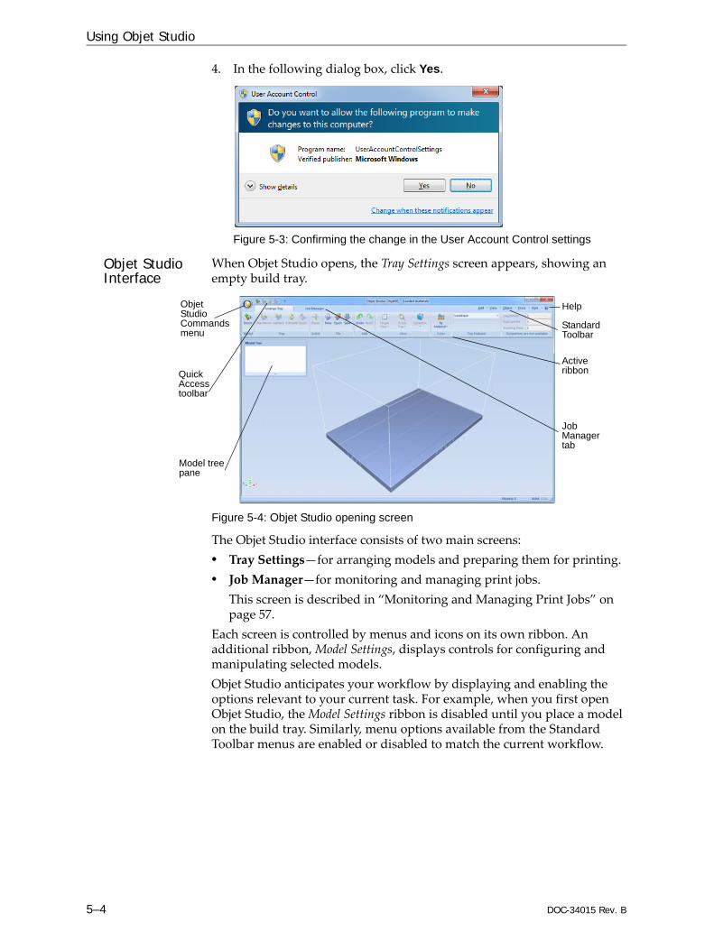
4. In the following dialog box, click Yes.
Figure 5-3: Confirming the change in the User Account Control settings
Objet Studio Interface
When Objet Studio opens, the Tray Settings screen appears, showing an empty build tray.
Figure 5-4: Objet Studio opening screen
The Objet Studio interface consists of two main screens:• Tray Settings—for arranging models and preparing them for printing.• Job Manager—for monitoring and managing print jobs.
This screen is described in “Monitoring and Managing Print Jobs” on page 57.
Each screen is controlled by menus and icons on its own ribbon. An additional ribbon, Model Settings, displays controls for configuring and manipulating selected models.Objet Studio anticipates your workflow by displaying and enabling the options relevant to your current task. For example, when you first open Objet Studio, the Model Settings ribbon is disabled until you place a model on the build tray. Similarly, menu options available from the Standard Toolbar menus are enabled or disabled to match the current workflow.
Objet Studio Commands menu
Model tree pane
Quick Access toolbar
Job Manager tab
Help
Active ribbon
Standard Toolbar
DOC-34015 Rev. B 5–5
Objet30 User Guide
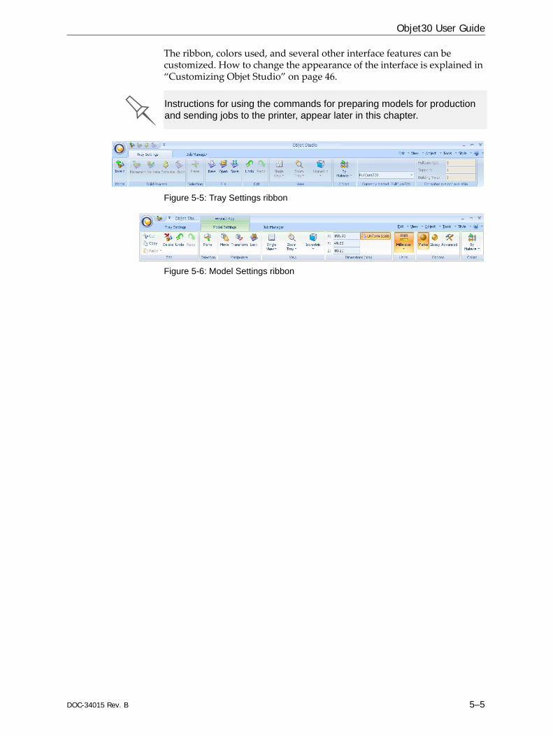
The ribbon, colors used, and several other interface features can be customized. How to change the appearance of the interface is explained in “Customizing Objet Studio” on page 46.
Figure 5-5: Tray Settings ribbon
Figure 5-6: Model Settings ribbon
Instructions for using the commands for preparing models for production and sending jobs to the printer, appear later in this chapter.
Using Objet Studio
5–6 DOC-34015 Rev. B
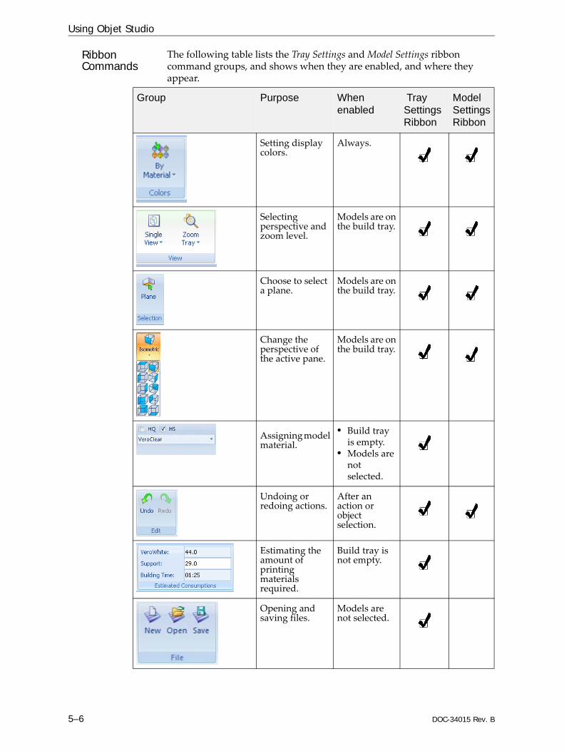
Ribbon Commands
The following table lists the Tray Settings and Model Settings ribbon command groups, and shows when they are enabled, and where they appear.
Group Purpose When enabled
Tray Settings Ribbon
Model Settings Ribbon
Setting display colors.
Always.
Selecting perspective and zoom level.
Models are on the build tray.
Choose to select a plane.
Models are on the build tray.
Change the perspective of the active pane.
Models are on the build tray.
Assigning model material.
• Build tray is empty.
• Models are not selected.
Undoing or redoing actions.
After an action or object selection.
Estimating the amount of printing materials required.
Build tray is not empty.
Opening and saving files.
Models are not selected.

DOC-34015 Rev. B 5–7
Objet30 User Guide
Placing model files on the build tray.
Always.
Pre‐build/build commands.
Models are on the build tray.
Setting model dimensions.
A model is selected.
Cutting, copying, pasting and deleting models.
A model is selected.
Moving, rotating and resizing models.
A model is selected.
Assigning model finish and setting support strength/“hollow.”
A model is selected.
Setting a model’s unit of measure (millimeters or inches).
A model is selected.
Group Purpose When enabled
Tray Settings Ribbon
Model Settings Ribbon
To quickly identify an icon, move the cursor over it to display a tooltip. The “Undo” and “Redo” tooltips change to reflect your last Objet Studio action.
After activating some of the ribbon commands (by clicking them), they remain active until you click another button or until you press the Escape key.
Using Objet Studio
5–8 DOC-34015 Rev. B
Objet Studio Commands Menu
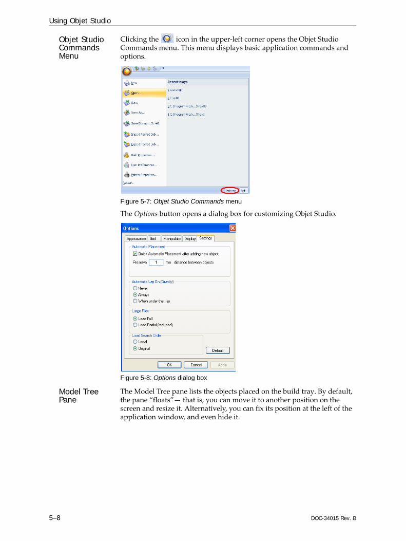
Clicking the icon in the upper‐left corner opens the Objet Studio Commands menu. This menu displays basic application commands and options.
Figure 5-7: Objet Studio Commands menu
The Options button opens a dialog box for customizing Objet Studio.
Figure 5-8: Options dialog box
Model Tree Pane
The Model Tree pane lists the objects placed on the build tray. By default, the pane “floats”— that is, you can move it to another position on the screen and resize it. Alternatively, you can fix its position at the left of the application window, and even hide it.
DOC-34015 Rev. B 5–9
Objet30 User Guide
Preparing Models for ProductionModel preparation involves the following basic steps:1. Place objects on the build tray.2. If necessary, manipulate the object’s orientation and position.3. Select the material and model finish.
OBJDF Files: Overview
An objdf file describes both the geometry of a single object and the material, and finish required to print it. You can use this file format to save a group of separate objects on the build tray as one unit, together with their relative positions and material.Further explanations of objdf files, and their features, appear throughout this chapter.
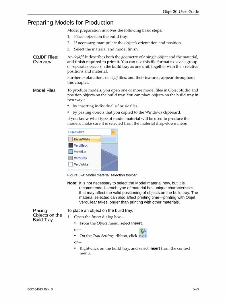
Model Files To produce models, you open one or more model files in Objet Studio and position objects on the build tray. You can place objects on the build tray in two ways:• by inserting individual stl or slc files.• by pasting objects that you copied to the Windows clipboard.If you know what type of model material will be used to produce the models, make sure it is selected from the material drop‐down menu.
Figure 5-9: Model material selection toolbar
Note: It is not necessary to select the Model material now, but it is recommended—each type of material has unique characteristics that may affect the valid positioning of objects on the build tray. The material selected can also affect printing time—printing with Objet VeroClear takes longer than printing with other materials.
Placing Objects on the Build Tray
To place an object on the build tray:1. Open the Insert dialog box—
• From the Object menu, select Insert.or—• On the Tray Settings ribbon, click .or—• Right‐click on the build tray, and select Insert from the context
menu.

Using Objet Studio
5–10 DOC-34015 Rev. B
The Insert dialog box appears.
Figure 5-10: Insert dialog box
2. In the Look in field, display the appropriate folder.3. In the Files of type field, select the file type to display.4. Select the desired file, and make sure that it appears in the File name
field.If the Preview check box is selected, the object is displayed in the dialog box, as shown in figure 5‐10.The Model Settings ribbon is displayed when objects are placed on the build tray.
5. Select any of the following options, as required:• Units—Millimeters or inches for the object’s units of measure.
The 3D file contains the objectʹs proportions, but not its units of measure. Therefore, make sure to correctly select either millimeters or inches when inserting an object. Otherwise, the size of the object on the build tray will be either much too large or much too small. To change the measurement units of objects already placed on the tray, see “Measurement Units” on page 24.
• Number of copies—How many copies of this object to place on the build tray.
• Orient Automatically—Automatically orient objects on the build tray for efficient model building.
Note: The Extents values displayed in the Coordinates section of the Insert dialog box, represent the maximum dimensions of the object on each axis. These dimensions correspond to the virtual “bounding box” surrounding the object see figure 5-36 on page 30).
DOC-34015 Rev. B 5–11
Objet30 User Guide
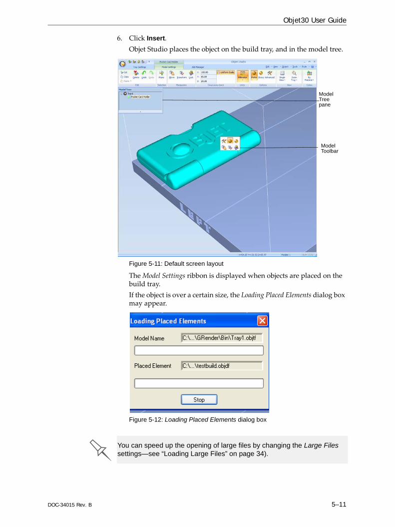
6. Click Insert.Objet Studio places the object on the build tray, and in the model tree.
Figure 5-11: Default screen layout
The Model Settings ribbon is displayed when objects are placed on the build tray.If the object is over a certain size, the Loading Placed Elements dialog box may appear.
Figure 5-12: Loading Placed Elements dialog box
Model Tree pane
Model Toolbar
You can speed up the opening of large files by changing the Large Files settings—see “Loading Large Files” on page 34).

Using Objet Studio
5–12 DOC-34015 Rev. B
Opening objdf filesBefore placing objdf files on the build tray, Objet Studio must extract the component stl files together with information about their relative position and model materials. To do this, Objet Studio creates a folder with the same name as the objdf file, in the same location.
Figure 5-13: Insert dialog box (objdf file)
DOC-34015 Rev. B 5–13
Objet30 User Guide
Opening Objet Tray Files
You can open trays that were saved as objtf files. This is useful, for example, if you saved a tray after preparing it for printing, and now you want to make changes before printing it.
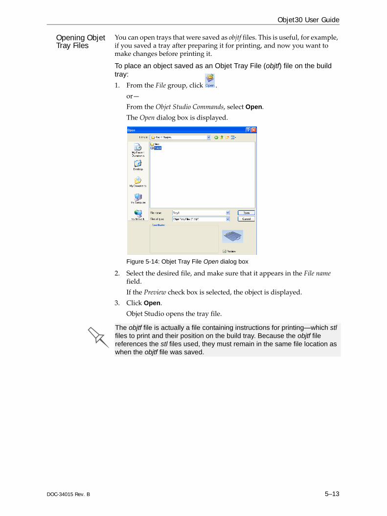
To place an object saved as an Objet Tray File (objtf) file on the build tray:1. From the File group, click .
or—From the Objet Studio Commands, select Open.The Open dialog box is displayed.
Figure 5-14: Objet Tray File Open dialog box
2. Select the desired file, and make sure that it appears in the File name field. If the Preview check box is selected, the object is displayed.
3. Click Open.Objet Studio opens the tray file.
The objtf file is actually a file containing instructions for printing—which stl files to print and their position on the build tray. Because the objtf file references the stl files used, they must remain in the same file location as when the objtf file was saved.

Using Objet Studio
5–14 DOC-34015 Rev. B
STL file loadingpreference
If there are identically named stl files in more than one location, you need to ensure that the correct component stl files are linked to the objtf file. For example, if there are identically named stl files on one drive and on a flash drive (this can occur if you copy the original files to a working folder), you can set the default location from which files are loaded.
To set the Load Order:1. From the Tools menu, select Options.
or—In the Objet Studio Commands Menu, click Options.
2. In the Options dialog box, display the Settings tab.
Figure 5-15: Options dialog box, Settings tab
3. Under Load Search Order, select an option:• Local—to load files from the location where they were last saved.• Original—to load files in their original location.
4. Click OK.

DOC-34015 Rev. B 5–15
Objet30 User Guide
Quick-Access Model Commands
You can access common commands for working with objects on the build tray with the convenient Model Toolbar and context menus.
Model Toolbar Select an object in the tray to display the Model Toolbar that contains icons to perform common tasks.
Figure 5-16: Model Toolbar
The table below describes the Model Toolbar icons.
Right-click modelmenu
If you right‐click on an object, a pop‐up context menu is displayed from which you can also select the model finish, change its position and scale, and set the Grid Style and Hollow options.
Icon Description
Applies a matte finish to the model.
Applies a glossy finish to the model.
Opens the Advanced Properties dialog box for setting the Grid Style and the Hollow option.
Enables dragging an object (see page 5‐25).
Opens the Transform dialog box for changing the object’s position and scale.
Toggles the Lock Model Orientation setting.
You can also create a Quick Access toolbar with your most commonly used icons grouped together. See “Creating a Quick Access Toolbar” on page 46.

Using Objet Studio
5–16 DOC-34015 Rev. B
Copying and Pasting Objects
If you need to duplicate objects on the build tray, you can insert the same object from its file more than once. An easier way, however, is to copy and paste the object. You can copy objects from the build tray or the model tree. The objects copied remain in the Windows clipboard until you paste them onto the build tray. You can also copy objects from one tray and paste them onto another, in the same way as you copy text from one document and paste it into another one. However, Objet Studio allows only one tray to be open at a time. For each build tray you need to work with (at the same time), you must open a separate Objet Studio window, by running the application again (from the Windows Start menu).
You perform the Copy and Paste commands as in other Windows applications:• from the right‐click context menu.• by using keyboard shortcuts (Ctrl+C and Ctrl+V, respectively).The Paste Special command (from the object’s right‐click context menu) enables you to place duplicate objects even more efficiently:• You can specify the number of duplicates to place on the build tray at
once.• You can set the distance, on each axis, between the duplicate objects.• You can manipulate mirror images of the original object, and flip them
on selected axes.
Figure 5-17: Paste Special dialog box
Having multiple Objet Studio windows open can be convenient when you need to manipulate or configure objects before inserting them in your production build tray. Copying and pasting also allows you to use objects already configured on previously-used build trays for newer projects.

DOC-34015 Rev. B 5–17
Objet30 User Guide
Selecting Objects
To manipulate an object on the build tray or assign characteristics to it (building style, for example), you must first select the object. You select an object by clicking it, either on the tray or in the model tree. Its image on the build tray changes color (to light blue, by default) and its name is highlighted in the model tree. You can select multiple objects by drawing a box around them with the mouse cursor, or by pressing the Ctrl or Shift keys while clicking additional objects.Alternatively, select or de‐select objects using the following Edit menu commands:• Select All• Invert Selection• Undo Select object
Figure 5-18: Edit menu
Surface Finish Models can be printed with a matte or glossy surface finish. To create a matte finish, the printer surrounds models with a thin layer of support material.
To set the model finish:1. Select the model.2. Select Matte or Glossy in one of the following places:
• Model Settings ribbon, Options group• Model Toolbar• right‐click context menu (when selecting the model)
You can configure Objet Studio to distinguish between objects’ surface finish on the build tray by color. To configure how Objet Studio displays objects, see “Setting Object Colors” on page 33.
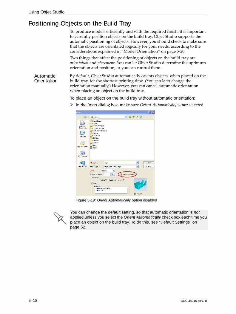
Using Objet Studio
5–18 DOC-34015 Rev. B
Positioning Objects on the Build TrayTo produce models efficiently and with the required finish, it is important to carefully position objects on the build tray. Objet Studio supports the automatic positioning of objects. However, you should check to make sure that the objects are orientated logically for your needs, according to the considerations explained in “Model Orientation” on page 5‐20.Two things that affect the positioning of objects on the build tray are orientation and placement. You can let Objet Studio determine the optimum orientation and position, or you can control them.
Automatic Orientation
By default, Objet Studio automatically orients objects, when placed on the build tray, for the shortest printing time. (You can later change the orientation manually.) However, you can cancel automatic orientation when placing an object on the build tray.
To place an object on the build tray without automatic orientation:In the Insert dialog box, make sure Orient Automatically is not selected.
Figure 5-19: Orient Automatically option disabled
You can change the default setting, so that automatic orientation is not applied unless you select the Orient Automatically check box each time you place an object on the build tray. To do this, see “Default Settings” on page 52.
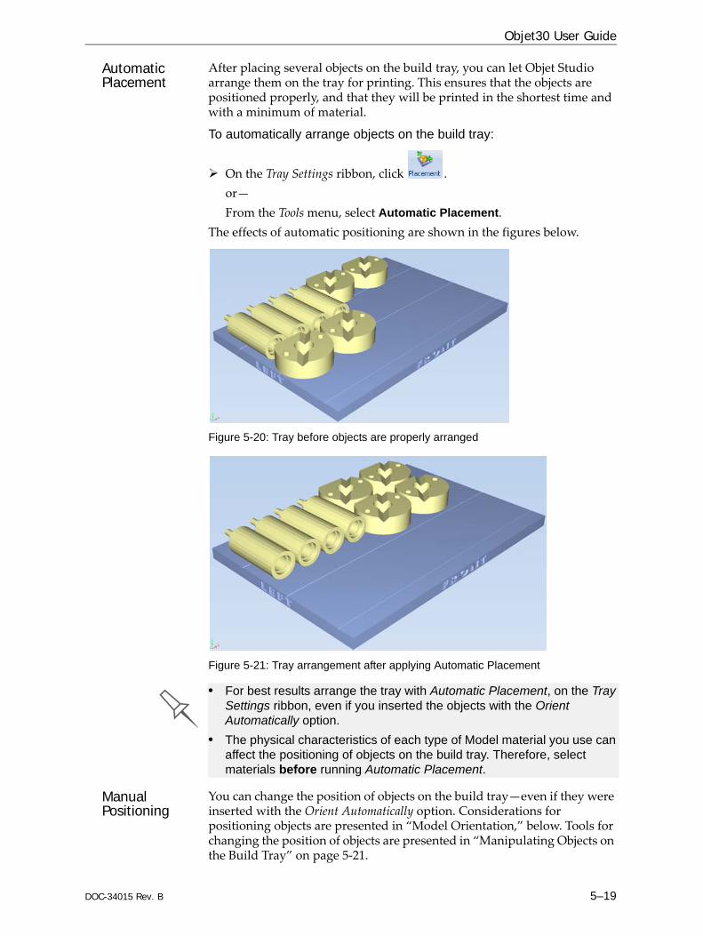
DOC-34015 Rev. B 5–19
Objet30 User Guide
Automatic Placement
After placing several objects on the build tray, you can let Objet Studio arrange them on the tray for printing. This ensures that the objects are positioned properly, and that they will be printed in the shortest time and with a minimum of material.
To automatically arrange objects on the build tray:
On the Tray Settings ribbon, click .or—From the Tools menu, select Automatic Placement.
The effects of automatic positioning are shown in the figures below.
Figure 5-20: Tray before objects are properly arranged
Figure 5-21: Tray arrangement after applying Automatic Placement
Manual Positioning
You can change the position of objects on the build tray—even if they were inserted with the Orient Automatically option. Considerations for positioning objects are presented in “Model Orientation,” below. Tools for changing the position of objects are presented in “Manipulating Objects on the Build Tray” on page 5‐21.
• For best results arrange the tray with Automatic Placement, on the Tray Settings ribbon, even if you inserted the objects with the Orient Automatically option.
• The physical characteristics of each type of Model material you use can affect the positioning of objects on the build tray. Therefore, select materials before running Automatic Placement.
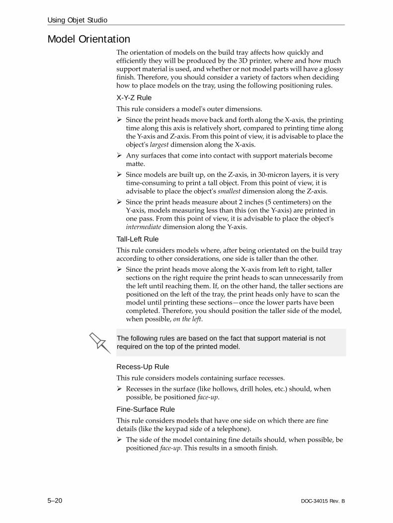
Using Objet Studio
5–20 DOC-34015 Rev. B
Model OrientationThe orientation of models on the build tray affects how quickly and efficiently they will be produced by the 3D printer, where and how much support material is used, and whether or not model parts will have a glossy finish. Therefore, you should consider a variety of factors when deciding how to place models on the tray, using the following positioning rules.
X-Y-Z RuleThis rule considers a modelʹs outer dimensions.
Since the print heads move back and forth along the X‐axis, the printing time along this axis is relatively short, compared to printing time along the Y‐axis and Z‐axis. From this point of view, it is advisable to place the objectʹs largest dimension along the X‐axis.Any surfaces that come into contact with support materials become matte.Since models are built up, on the Z‐axis, in 30‐micron layers, it is very time‐consuming to print a tall object. From this point of view, it is advisable to place the objectʹs smallest dimension along the Z‐axis.Since the print heads measure about 2 inches (5 centimeters) on the Y‐axis, models measuring less than this (on the Y‐axis) are printed in one pass. From this point of view, it is advisable to place the objectʹs intermediate dimension along the Y‐axis.
Tall-Left RuleThis rule considers models where, after being orientated on the build tray according to other considerations, one side is taller than the other.
Since the print heads move along the X‐axis from left to right, taller sections on the right require the print heads to scan unnecessarily from the left until reaching them. If, on the other hand, the taller sections are positioned on the left of the tray, the print heads only have to scan the model until printing these sections—once the lower parts have been completed. Therefore, you should position the taller side of the model, when possible, on the left.
Recess-Up RuleThis rule considers models containing surface recesses.
Recesses in the surface (like hollows, drill holes, etc.) should, when possible, be positioned face‐up.
Fine-Surface RuleThis rule considers models that have one side on which there are fine details (like the keypad side of a telephone).
The side of the model containing fine details should, when possible, be positioned face‐up. This results in a smooth finish.
The following rules are based on the fact that support material is not required on the top of the printed model.

DOC-34015 Rev. B 5–21
Objet30 User Guide
Avoid Support-Material RuleThis rule considers models that have large holes or hollows, open on at least one side (like a pipe or a container).
It may be advantageous to print a model standing up, so support material does not fill the hollow, even though printing the model lying down would be much faster.
Manipulating Objects on the Build TrayPositioning Objects on the Z-Axis
When you use the automatic positioning option to arrange objects on the build tray (see “Automatic Orientation” on page 5‐18), the objects are positioned directly on the tray. If you do not insert objects with automatic positioning, they often appear either above or below the tray.
To position objects directly on the tray: 1. Select the object.2. From the Object menu, select Lay On.
To ensure that objects are always positioned directly on the tray:1. From the Tools menu, select Options, and display the Settings tab.
Figure 5-22: Options dialog box, Settings tab
2. In the Automatic Lay On (Gravity) section, select Always.
Other Z-axis options (in the Automatic Lay On section):• When under the tray—The display of objects that are below the build
tray is automatically changed so that the object is at tray level.• Never—The display of objects that are above or below the build tray is
not changed.
In practice, the Objet system prints all models on the build tray on a one-millimeter bed of support material. The importance of positioning objects directly on the build tray with Objet Studio is to correctly display the objects on the screen.

Using Objet Studio
5–22 DOC-34015 Rev. B
Valid Object Placement
You can ensure that models do not overlap when you position them on the build tray, and that they do not extend beyond the tray.
To ensure valid object placement: 1. From the Tools menu, select Constraints Settings.
Figure 5-23: Constraints Settings dialog box
2. Select Dynamic check to identify:• invalid object placement while placing objects—On Drop selected.• invalid object placement after moving objects—While Drag selected.• objects placed beyond the tray’s boundaries—Outside Tray selected.• objects that overlap—Object Collision selected.
Note: Remember that Objet Studio calculates the space occupied by an object including the “bounding box” surrounding it (see figure 5-36 on page 30).
Even if you do not use Dynamic Check when placing objects on the build tray, Objet Studio automatically checks if there is a problem with the positioning of objects on the tray before sending it to the printer. You can also manually check for problems after positioning objects (see “Tray Validation” on page 37).

DOC-34015 Rev. B 5–23
Objet30 User Guide
Using a Grid to Position Objects
Displaying a grid on the image of the build tray can be useful when positioning objects. To use the grid features, select the following menu options.
You can review and configure grid settings—and apply them—from the Options dialog box.
To view and change grid settings:1. From the Tools menu, select Options, and display the Grid tab.
The current grid settings are displayed.
Figure 5-24: Options dialog box, Grid tab
2. As required, change the settings, and select or clear the check boxes.3. Click Apply or OK.
Menu Option Result
Tools > Grid Displays a grid on the build tray.
Tools > Snap to grid When moving the object, it aligns with the nearest grid line.
Tools > Options > Grid
Enables you to change the grid origin (X‐ and Y‐axis meeting point) and appearance.

Using Objet Studio
5–24 DOC-34015 Rev. B
Measurement Units
3D files contain an objectʹs proportions, but not its units of measure. Therefore, make sure to correctly select either millimeters or inches when inserting an object. Otherwise, the size of the object on the build tray will be either much too large or much too small.
To set the measurement units when inserting an object:In the Insert dialog box, Units field, select Millimeter or Inch:
Figure 5-25: Units field in the Insert dialog box
To change measurement units for a selected object from the Model Settings ribbon:1. Open the Units flyout toolbar.
Figure 5-26: Units flyout toolbar
2. Select the measurement units desired.
To change measurement units for a selected object from the Standard Toolbar:1. From the Object menu, select Change Units.
Figure 5-27: Model Units dialog box
2. In the Model Units dialog box, change the setting and click OK.

DOC-34015 Rev. B 5–25
Objet30 User Guide
Setting Model Dimensions
You can change an object’s dimensions by changing its size on the X‐, Y‐, and Z‐axes, from the Dimensions group on the Model Settings ribbon.
Figure 5-28: Dimensions on the Model Settings ribbon
• If Uniform Scale is enabled, changing the object’s dimension on one axis affects the other dimensions, proportionately.
• After changing a measurement, press Enter or click in another field in the Dimensions group.
Note: You can change the height of the objects on the build tray only if this is allowed by the Objet Studio settings (see “Positioning Objects on the Z-Axis” on page 5-21).
Repositioning Objects
You can manually move and rotate an object on the build tray with the arrow keys, or by dragging it with the mouse.
To manually manipulate an object:1. Select an object by clicking it on the build tray, or in the model tree
pane.
2. Click on the Model Toolbar, or on the Model Settings ribbon.A frame appears around the object, and the cursor changes to indicate that the object can be moved.
Figure 5-29: Manually moving an object
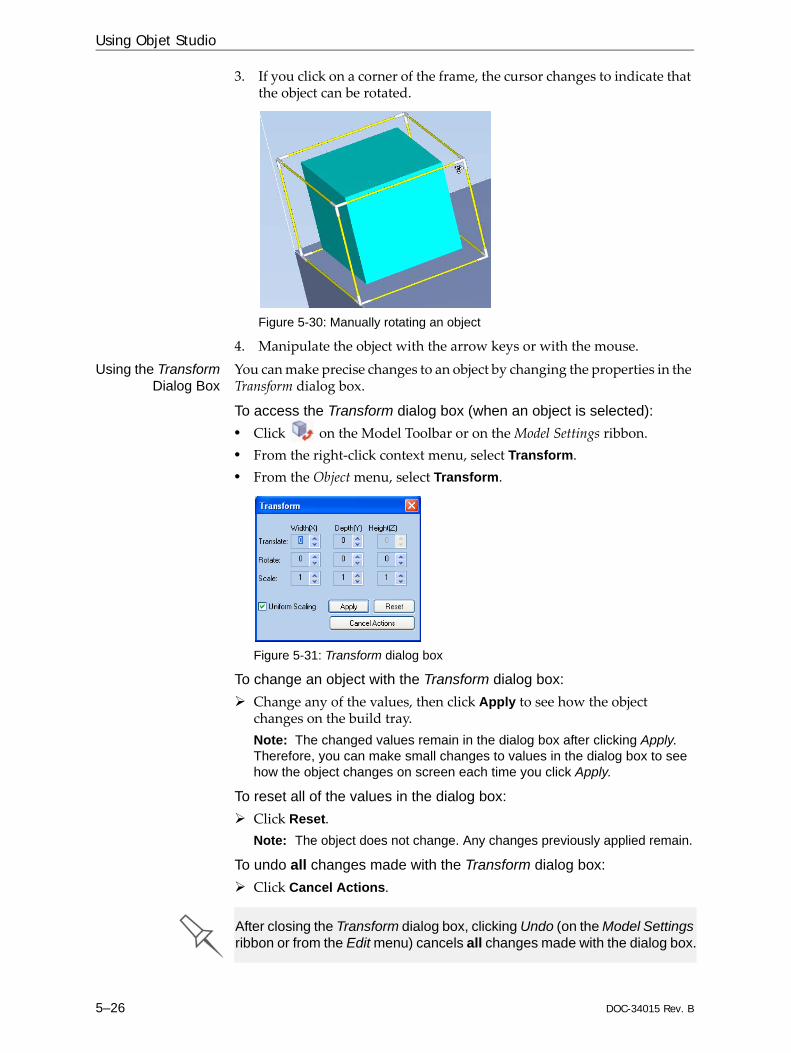
Using Objet Studio
5–26 DOC-34015 Rev. B
3. If you click on a corner of the frame, the cursor changes to indicate that the object can be rotated.
Figure 5-30: Manually rotating an object
4. Manipulate the object with the arrow keys or with the mouse.Using the Transform
Dialog BoxYou can make precise changes to an object by changing the properties in the Transform dialog box.
To access the Transform dialog box (when an object is selected):• Click on the Model Toolbar or on the Model Settings ribbon.• From the right‐click context menu, select Transform.• From the Object menu, select Transform.
Figure 5-31: Transform dialog box
To change an object with the Transform dialog box:Change any of the values, then click Apply to see how the object changes on the build tray. Note: The changed values remain in the dialog box after clicking Apply. Therefore, you can make small changes to values in the dialog box to see how the object changes on screen each time you click Apply.
To reset all of the values in the dialog box:Click Reset.Note: The object does not change. Any changes previously applied remain.
To undo all changes made with the Transform dialog box:Click Cancel Actions.
After closing the Transform dialog box, clicking Undo (on the Model Settings ribbon or from the Edit menu) cancels all changes made with the dialog box.

DOC-34015 Rev. B 5–27
Objet30 User Guide
Changing an Object’s Orientation
There are several methods for changing the orientation of objects on the build tray.
To rotate an object:Select the object and use the Object menu options (see also “Repositioning Objects” on page 5‐25).
To re-align an object’s plane:1. On the Tray Settings or Model Settings ribbon, click .
or—From the Tools menu, select Plane Alignment > Select Plane.
2. Click on part of an object on the build tray.The selected plane is displayed.
Figure 5-32: Aligning by plane
3. On the Alignment toolbar, click an appropriate icon to change the alignment. or—From the Tools menu, select Plane Alignment, and select an alignment option.
Figure 5-33: Tools menu, Plane Alignment options
Alignment toolbar
Selected plane
Using Objet Studio
5–28 DOC-34015 Rev. B
To cancel plane selection after re-aligning objects on the build tray:
On the Tray Settings or Model Settings ribbon, click .or—From the Tools menu, select Plane Alignment > Select Plane.
To flip an object 180 degrees on any axis:1. Select the object.2. From the Object menu, select Flip > Flip X / Flip Y / Flip Z.
To make precise changes to the object’s orientation on any axis:1. Select the object. 2. Display the Transform dialog box (see figure 5‐31 on page 26).3. Change the Rotate parameters for each axis.
Freezing Model Orientation
If you manipulate an object on the build tray, you can freeze its orientation so that it does not change when you position it automatically (see “Automatic Placement” on page 5‐19).
To freeze an object:1. Select an object on the build tray.2. On the Model Settings ribbon, in the Manipulate group, or on the Model
Toolbar, click .
To unfreeze an object:Select the object and click (to de‐select it).
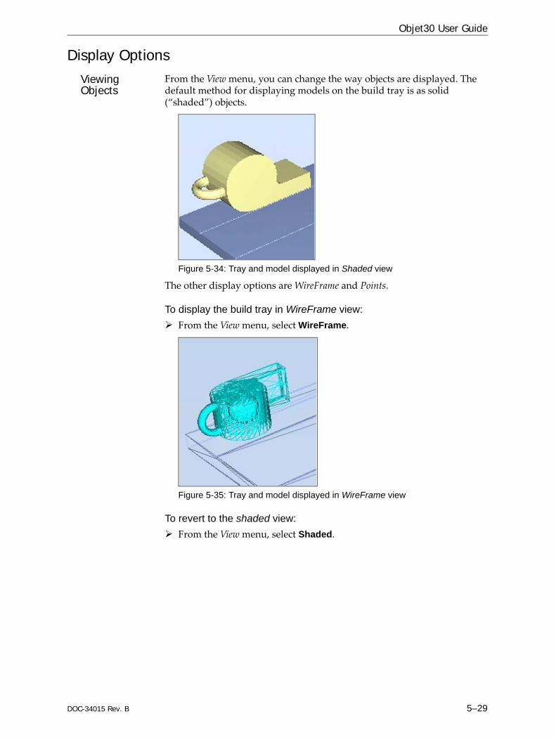
DOC-34015 Rev. B 5–29
Objet30 User Guide
Display OptionsViewing Objects
From the View menu, you can change the way objects are displayed. The default method for displaying models on the build tray is as solid (“shaded”) objects.
Figure 5-34: Tray and model displayed in Shaded view
The other display options are WireFrame and Points.
To display the build tray in WireFrame view:From the View menu, select WireFrame.
Figure 5-35: Tray and model displayed in WireFrame view
To revert to the shaded view:From the View menu, select Shaded.
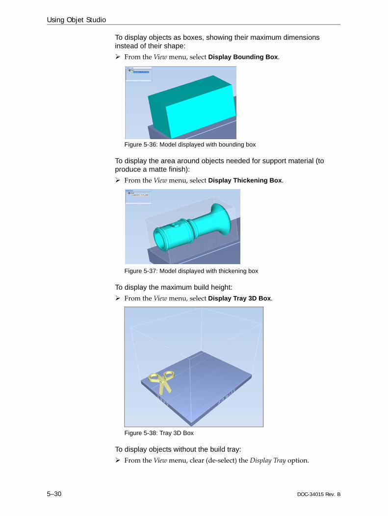
Using Objet Studio
5–30 DOC-34015 Rev. B
To display objects as boxes, showing their maximum dimensions instead of their shape:
From the View menu, select Display Bounding Box.
Figure 5-36: Model displayed with bounding box
To display the area around objects needed for support material (to produce a matte finish):
From the View menu, select Display Thickening Box.
Figure 5-37: Model displayed with thickening box
To display the maximum build height:From the View menu, select Display Tray 3D Box.
Figure 5-38: Tray 3D Box
To display objects without the build tray:From the View menu, clear (de‐select) the Display Tray option.

DOC-34015 Rev. B 5–31
Objet30 User Guide
Screen Layout Objet Studio automatically adjusts the default screen layout to display the optimum views of the build tray and the model tree. You can view models from different perspectives by changing the screen layout.
To change the screen layout:On the View flyout toolbar, select Single View, or 4 Views.
Figure 5-39: Screen layout icons
Single View is the default screen layout.4 Views displays perspective, top, front and right views.
Figure 5-40: Single-view screen layout
Figure 5-41: 4-view screen layout

Using Objet Studio
5–32 DOC-34015 Rev. B
Tray Perspective
The default perspective of the build tray is “isometric.” You can change the perspective of the active window with one of ten options.
To change the perspective of the build tray in the active window:1. On the Tray Settings ribbon, open the Perspective flyout toolbar.
Figure 5-42: Perspective flyout toolbar
2. Click the icon that represents the desired perspective.Tray Positioning To view the tray and models from different directions, you can move the
tray around the screen and change its display angle.
To move the tray in the Objet Studio screen:Press the mouse wheel while moving the mouse.
Figure 5-43: Tray after moving it in the Objet Studio display
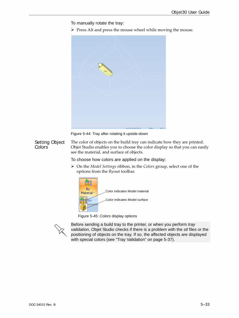
DOC-34015 Rev. B 5–33
Objet30 User Guide
To manually rotate the tray:Press Alt and press the mouse wheel while moving the mouse.
Figure 5-44: Tray after rotating it upside-down
Setting Object Colors
The color of objects on the build tray can indicate how they are printed. Objet Studio enables you to choose the color display so that you can easily see the material, and surface of objects.
To choose how colors are applied on the display:On the Model Settings ribbon, in the Colors group, select one of the options from the flyout toolbar.
Figure 5-45: Colors display options
Color indicates Model material
Color indicates Model surface
Before sending a build tray to the printer, or when you perform tray validation, Objet Studio checks if there is a problem with the stl files or the positioning of objects on the tray. If so, the affected objects are displayed with special colors (see “Tray Validation” on page 5-37).
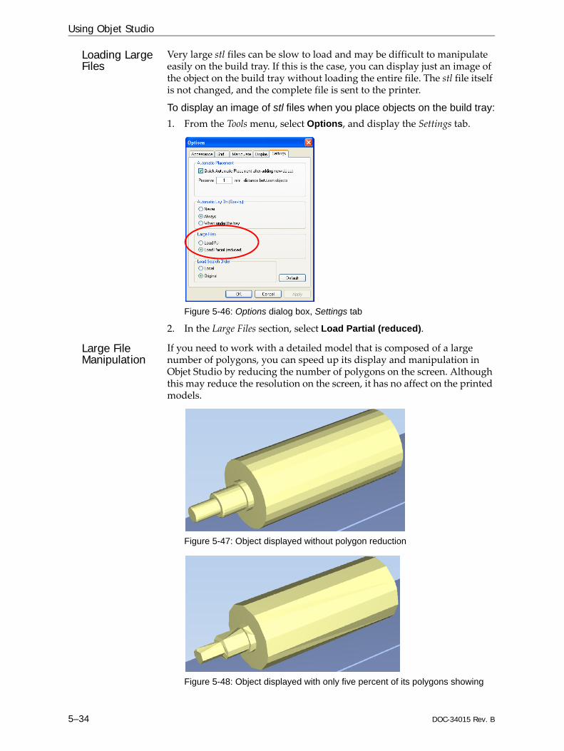
Using Objet Studio
5–34 DOC-34015 Rev. B
Loading Large Files
Very large stl files can be slow to load and may be difficult to manipulate easily on the build tray. If this is the case, you can display just an image of the object on the build tray without loading the entire file. The stl file itself is not changed, and the complete file is sent to the printer.
To display an image of stl files when you place objects on the build tray:1. From the Tools menu, select Options, and display the Settings tab.
Figure 5-46: Options dialog box, Settings tab
2. In the Large Files section, select Load Partial (reduced).
Large File Manipulation
If you need to work with a detailed model that is composed of a large number of polygons, you can speed up its display and manipulation in Objet Studio by reducing the number of polygons on the screen. Although this may reduce the resolution on the screen, it has no affect on the printed models.
Figure 5-47: Object displayed without polygon reduction
Figure 5-48: Object displayed with only five percent of its polygons showing

DOC-34015 Rev. B 5–35
Objet30 User Guide
To use polygon reduction:1. From the Tools menu, select Options.
or—In the Objet Studio Commands Menu, click Options.
2. In the Options dialog box, display the Display tab.
Figure 5-49: Options dialog box, Display tab
3. Select Enable Polygon Reduction.4. Select Polygon Reduction (Percent).5. Enter the percentage of total polygons to display.
When you click Apply, the display changes.
Note: The setting affects the static display (when the object is not being moved).
6. Set display options when the object is being moved (Display while changing view):• Bounding Box—A box representing the object’s maximum
dimensions is displayed.• Adaptive Polygon Reduction—Varying degrees of polygon reduction
are applied, as necessary.• Entire Object—No polygon reduction is applied.
7. To save these settings, so that they will be applied every time you place this object on the build tray, click Save Polygon Reduction Data.
8. Click Apply to see the results of the settings without closing the dialog box.
Selecting the Entire Object option cancels polygon reduction.

Using Objet Studio
5–36 DOC-34015 Rev. B
Object displayoptions
The display format affects how quickly objects display. For example, if you select Bounding Box, objects display faster than they do when you select Entire Object. You can choose display formats for objects when they are stationary (static view) and for when you are dragging them (changing view).
To select the object display preference while changing view, and in static view:1. Select to display objects:
• With a Bounding Box (see figure 5‐36 on page 30)• With Adaptive Polygon Reduction (changing view only)• With Polygon Reduction (static view only)• Entire Object
2. Click OK when done.
Zoom Options While manipulating objects, you often need to view them at different zoom levels.
To change the zoom level:On the ribbon, open the Zoom flyout toolbar and select an option:
Figure 5-50: Zoom flyout toolbar
Zoom Object focuses on the selected object.Zoom Tray displays the whole tray.Zoom by Rectangle allows you to display a section of the tray by selecting it with the mouse.
You can also zoom in and zoom out with the mouse wheel.
Zoom Object
Zoom Tray
Zoom by Rectangle
You can configure Objet Studio to automatically zoom in on the objects placed on the build tray. See “Automatic Zoom” on page 52.

DOC-34015 Rev. B 5–37
Objet30 User Guide
Handling Completed TraysAfter you have properly placed all objects on the build tray, you save the tray as an objtf file, which is sent to the 3D printer for production. But before saving the tray, you can check that there would be no problem producing it. You can also calculate how much material would be consumed during production and how much time this would take.
Tray Validation Before sending a job to the printer for production, you should check that the tray is “valid” and can be printed.
To validate that the tray can be printed:On the Tray Settings ribbon, in the Build Process group, click .or—From the Tools menu, select Placement Validation.If the tray is not valid, the color of the problematic models on the tray changes according to a pre‐set code.
Figure 5-51: Color code
Note: The “Both” color also indicates a problematic stl file.The validation status appears on the bar at the bottom of the screen.
Figure 5-52: Validation details in status bar

Using Objet Studio
5–38 DOC-34015 Rev. B
Production Estimates
Objet Studio enables you to calculate the time and material resources needed for producing trays before sending them to the printer. The time it takes Objet Studio to perform this calculation depends on the number of objects on the tray and their complexity. Calculating the production estimate for a full tray could take up to 15 minutes, depending on your computer’s specifications.
To calculate the time and materials needed for producing the current tray:
On the Tray Settings ribbon, in the Build Process group, click .While the estimate is being calculated, a progress bar is displayed—on the right side of the status bar (at the bottom of the screen).
Figure 5-53: Estimate progress bar
When Objet Studio finishes calculating the production resources, the results are displayed in the Estimated Consumptions group on the Tray Settings ribbon.
Figure 5-54: Production resource calculation
E-mailing Objet Digital Files
You can easily e‐mail objdf files using Microsoft® Office Outlook®. Sending objdf files is recommended (instead of stl files) because the size of a file is typically reduced by more than half. An added benefit is that the objdf file contains the model‐material information for the object.
To e-mail a file:1. From the Tools menu, select Email Objet Digital File.
Outlook opens with the file attached and Subject details added to the e‐mail form.
2. Enter the e‐mail address and send the file.
Cancel
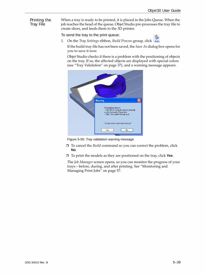
DOC-34015 Rev. B 5–39
Objet30 User Guide
Printing the Tray File
When a tray is ready to be printed, it is placed in the Jobs Queue. When the job reaches the head of the queue, Objet Studio pre‐processes the tray file to create slices, and feeds them to the 3D printer.
To send the tray to the print queue:1. On the Tray Settings ribbon, Build Process group, click .
If the build tray file has not been saved, the Save As dialog box opens for you to save it now.Objet Studio checks if there is a problem with the positioning of objects on the tray. If so, the affected objects are displayed with special colors (see “Tray Validation” on page 37), and a warning message appears.
Figure 5-55: Tray validation warning message
To cancel the Build command so you can correct the problem, click No.To print the models as they are positioned on the tray, click Yes.
The Job Manager screen opens, so you can monitor the progress of your trays—before, during, and after printing. See “Monitoring and Managing Print Jobs” on page 57.
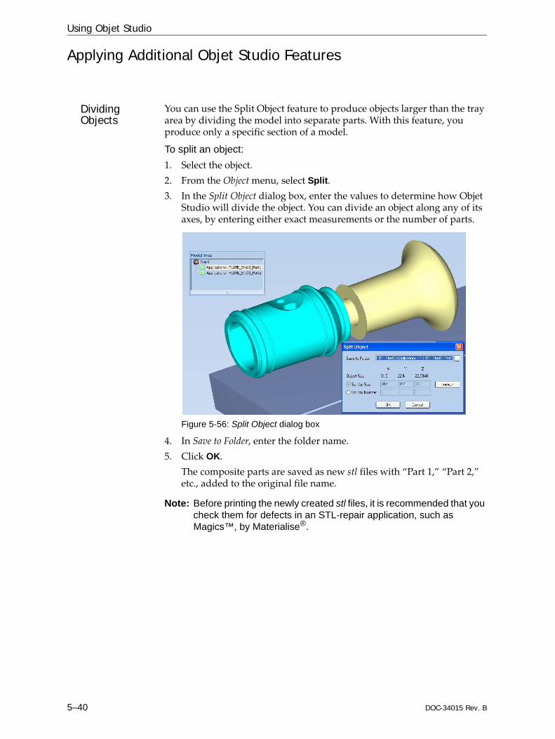
Using Objet Studio
5–40 DOC-34015 Rev. B
Applying Additional Objet Studio Features
Dividing Objects
You can use the Split Object feature to produce objects larger than the tray area by dividing the model into separate parts. With this feature, you produce only a specific section of a model.
To split an object:1. Select the object.2. From the Object menu, select Split.3. In the Split Object dialog box, enter the values to determine how Objet
Studio will divide the object. You can divide an object along any of its axes, by entering either exact measurements or the number of parts.
Figure 5-56: Split Object dialog box
4. In Save to Folder, enter the folder name.5. Click OK.
The composite parts are saved as new stl files with “Part 1,” “Part 2,” etc., added to the original file name.
Note: Before printing the newly created stl files, it is recommended that you check them for defects in an STL-repair application, such as Magics™, by Materialise®.

DOC-34015 Rev. B 5–41
Objet30 User Guide
Choosing the Support Strength
When producing models, support material fills some hollow and empty sections (see “Model Orientation” on page 5‐20). Objet Studio allows you to adjust the strength of the structure formed with the support material. This adjustment is useful when producing either large/massive models or small/delicate models. For most purposes, the default setting provides adequate support strength.
To change the strength of the support structure used when printing a model:1. Select a model on the tray.2. On the Model Settings ribbon, in the Options group, click .
or—• On the Model Toolbar, click .or—• From the right‐click context menu, select Advanced Properties.The Advanced Properties dialog box opens.
Figure 5-57: Advanced Properties dialog box
3. In the Grid Style section, choose the support strength suitable for the selected model. You can select a different support strength for each model on the tray.• Standard—for models needing average support (most models).• Heavy—for large models needing much support.• Lite—for delicate models needing little support. (This setting makes
it easy to remove the support material.)4. Click Apply.

Using Objet Studio
5–42 DOC-34015 Rev. B
“Hollow”— Filling Models with Support Material
Many objects placed on the tray from stl files are “solid.” This means that, when printed, the model will be completely filled with model material. Often, especially with large objects, this is unnecessary. Instead, the model can be filled with support material, which is less costly. It is also advisable to fill models with support material when preparing them for investment casting, since this material burns off more quickly during the process of making the cast.Objet Studio enables you to print objects on the tray with an outer shell of model material and a center filled with support material. When using this feature, called “Hollow,” the thickness of the shell should be no less than 0.5 millimeters.
To use the Hollow feature:1. Select a model on the tray.
or—• On the Model Toolbar, click .or—• From the right‐click context menu, select Advanced Properties.The Advanced Properties dialog box opens.
2. Select Hollow.
Figure 5-58: Advanced Properties dialog box
3. Set the shell thickness, in millimeters.4. Click Apply.
Note: There is no change in the display of objects in Objet Studio when Hollow is selected.
To inspect, change or cancel the Hollow setting:1. Select a model on the tray.2. Access the Advanced Properties dialog box, as above.3. If you change or cancel the Hollow setting, click Apply.

DOC-34015 Rev. B 5–43
Objet30 User Guide
Displaying the Cross Section of Objects
The Section feature enables you to view the interior of an object by “slicing” it on any axis. You can then manipulate the object to inspect the interior from different angles. This may be important for deciding on the type of support necessary when producing the model (see “Choosing the Support Strength” on page 5‐41). Displaying an object’s cross section only affects how the tray is displayed on the screen; it does not change the object itself.
To display a cross section of the tray:1. From the Tools menu, select Section.
The Section dialog box opens.
Figure 5-59: Section dialog box
2. Select Enable Clipping.3. Use the slider controls for the X‐, Y‐, and Z‐axes to cut the tray so that
you see the cross section you want.
Figure 5-60: Whole view Figure 5-61: Cross-section view, after using the Z-slider
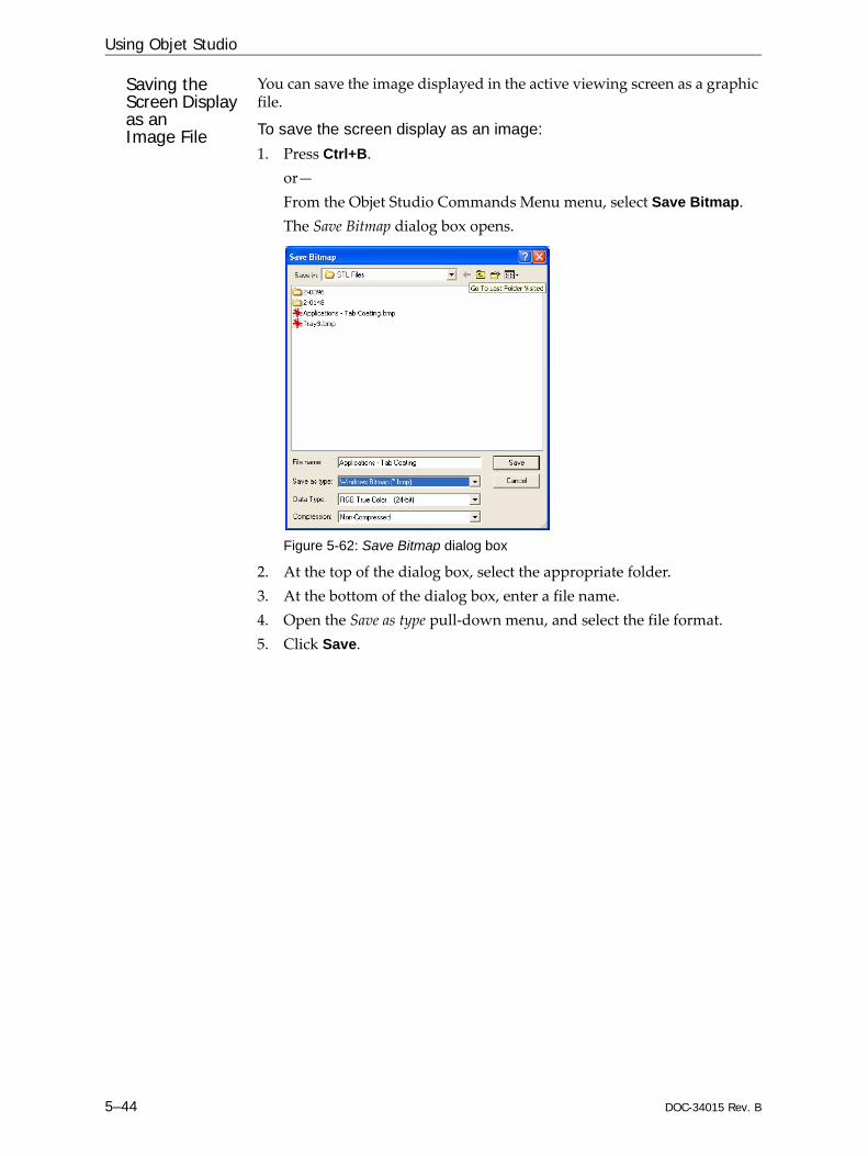
Using Objet Studio
5–44 DOC-34015 Rev. B
Saving the Screen Display as an Image File
You can save the image displayed in the active viewing screen as a graphic file.
To save the screen display as an image:1. Press Ctrl+B.
or— From the Objet Studio Commands Menu menu, select Save Bitmap.The Save Bitmap dialog box opens.
Figure 5-62: Save Bitmap dialog box
2. At the top of the dialog box, select the appropriate folder.3. At the bottom of the dialog box, enter a file name.4. Open the Save as type pull‐down menu, and select the file format.5. Click Save.
DOC-34015 Rev. B 5–45
Objet30 User Guide
Exporting and Importing Objet Build Trays
When you save build trays in Objet Studio, they are saved as objtf files. These files contain instructions to Objet Studio and to Objet printers for displaying and producing the stl files used on the tray. To conveniently save all of the files that comprise the build tray, for storing the job, or for transferring it to another location, Objet Studio compresses them into one objzf file. To later use the objzf file, the file must first be expanded in Objet Studio and its component files saved.
Note: If you export an objzf file containing a stl file originally saved as read-only, you cannot open (import) this objzf file to the folder where the read-only stl file is saved.
To create an objzf file:1. From the Objet Studio Commands Menu menu, select Export Packed
Job.The Save As dialog box opens.
2. Select the appropriate folder and change the file name (if necessary).3. Click Save.
To open an objzf file:Double‐click on the objtf file.or—
1. From the Objet Studio Commands Menu menu, select Import Packed Job.
2. In the Open dialog box, display the appropriate folder and select the file.
3. In the Browse for Folder dialog box, display the folder in which you want Objet Studio to expand the compressed file, and click OK.The objtf file and associated stl files are expanded and placed in the selected folder, and the tray is displayed in Objet Studio.
Note: You can also export a print job as an objzf file from the Job Manager screen—see “Exporting Jobs (objzf)” on page 69.
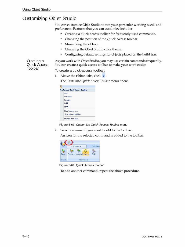
Using Objet Studio
5–46 DOC-34015 Rev. B
Customizing Objet StudioYou can customize Objet Studio to suit your particular working needs and preferences. Features that you can customize include:
• Creating a quick‐access toolbar for frequently used commands.• Changing the position of the Quick Access toolbar.• Minimizing the ribbon.• Changing the Objet Studio color theme.• Configuring default settings for objects placed on the build tray.
Creating a Quick Access Toolbar
As you work with Objet Studio, you may use certain commands frequently. You can create a quick‐access toolbar to make your work easier.
To create a quick-access toolbar:1. Above the ribbon tabs, click .
The Customize Quick Access Toolbar menu opens.
Figure 5-63: Customize Quick Access Toolbar menu
2. Select a command you want to add to the toolbar.An icon for the selected command is added to the toolbar.
Figure 5-64: Quick Access toolbar
To add another command, repeat the above procedure.

DOC-34015 Rev. B 5–47
Objet30 User Guide
3. To choose from a wider range of commands:• From the Customize Quick Access Toolbar menu (see figure 5‐63 on
page 46), select More Commands.or—• Right‐click on the Objet Studio Commands icon, or elsewhere on the
ribbon, and select Customize Quick Access Toobar.
Figure 5-65: Right-click ribbon menu
The Options dialog box opens.
Figure 5-66: Quick Access Toobar Options dialog box
4. Open the drop‐down list and select either Popular Commands or Commands not on the Ribbon.
5. Select a command and click Add.6. Click OK.
Hiding the Ribbon
To make more room for displaying the build tray, you can hide the Objet Studio ribbons.
To hide the ribbons:1. Right‐click anywhere on the ribbon or on the menu bar, or in the Objet
Studio Commands Menu .2. Select Minimize the Ribbon.
The ribbons disappear, but you can temporarily display the ribbon icons by clicking Tray Settings or Job Manager on the menu bar. When you next click outside of the ribbon, it disappears again.
To return the permanent ribbon display:Repeat the steps above to cancel Minimize the Ribbon.

Using Objet Studio
5–48 DOC-34015 Rev. B
Display Colors You can customize some of the colors used for displaying Objet Studio screens and for displaying objects on the build tray.
To change the colors used in Objet Studio screens:1. From the Tools menu, select Options.
Figure 5-67: Display settings
2. In the Appearance tab of the Options dialog box, you can configure the display.• The Mode selection determines how models appear on the build
tray. The default method for displaying models on the build tray is as solid (“shaded”) objects. The other options are WireFrame and Points.
• If Shaded is selected, you can display the model on the tray as a see‐through object.
Figure 5-68: Transparent display
• Double‐click the color patches to customize colors.• The Windows Background Color settings enable you to change the
color behind the build tray—with either a solid or a two‐color gradient.
• To return to the default display settings, click Default.
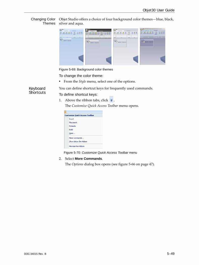
DOC-34015 Rev. B 5–49
Objet30 User Guide
Changing ColorThemes
Objet Studio offers a choice of four background color themes—blue, black, silver and aqua.
Figure 5-69: Background color themes
To change the color theme:• From the Style menu, select one of the options.
Keyboard Shortcuts
You can define shortcut keys for frequently used commands.
To define shortcut keys:1. Above the ribbon tabs, click .
The Customize Quick Access Toolbar menu opens.
Figure 5-70: Customize Quick Access Toolbar menu
2. Select More Commands.The Options dialog box opens (see figure 5‐66 on page 47).

Using Objet Studio
5–50 DOC-34015 Rev. B
3. Click Customize.The Customize Keyboard dialog box appears.
Figure 5-71: Customize Keyboard dialog box
4. Select command Categories to display all the commands in that category, for example, all the Model Settings commands. Current shortcut keys are displayed.
5. Enter the shortcut key in the Press new shortcut key field, and click Assign.
6. If you want to redefine all shortcut keys, click Reset All.
Setting User Preferences
You can change several Objet Studio settings that affect objects placed on the build tray.
To change default settings:From the Objet Studio Commands Menu, select User Preferences.
Figure 5-72: Setting work preferences
• Building Style—see “Surface Finish” on page 17.• Grid Style—see “Using a Grid to Position Objects” on page 23.• Application Settings—see “Choosing the Support Strength” on page 41,
and “Freezing Model Orientation” on page 28.

DOC-34015 Rev. B 5–51
Objet30 User Guide
Professional Mode FeaturesSome advanced features of Objet Studio are only accessible in Professional Mode.
To see the current Objet Studio setting:Open the Tools menu.
Figure 5-73: Tools menu, showing Professional Mode selected
If Professional Mode is selected, advanced features are displayed.
To change the Professional Mode setting:1. From the Tools menu, select Professional Mode.
The following message is displayed, reminding you that the change will only take effect the next time you open Objet Studio—even though the check mark next to the Professional Mode option appears immediately.
Figure 5-74: Configuration-change message
2. Close and re‐open Objet Studio to use the Professional Mode features.

Using Objet Studio
5–52 DOC-34015 Rev. B
Default Settings
You can control the default settings of several Objet Studio features from the Advanced tab of the Options dialog box.
To display the Options dialog box From the Tools menu, select Options.or—In the Objet Studio Commands Menu, click Options.
Figure 5-75: Options dialog box, Advanced tab
AutomaticOrientation
By default, when Objet Studio places objects on the build tray, it orients them optimally, for the shortest printing time. If necessary, you can choose to cancel automatic orientation each time you place an object on the build tray (see “Automatic Orientation” on page 18). In any case, when objects are on the build tray, you can change their orientation manually, if necessary—see “Model Orientation” on page 20.)
To change the default setting so that Automatic Orientation is disabled:In the Advanced section of the Options dialog box, clear the check box.
Automatic Zoom When Auto Zoom is selected in the Advanced section of the Options dialog box, the display zooms in, to display the objects placed on the build tray. This allows you to carefully inspect and manipulate the objects.By default, this feature is not enabled. In any case, you can change the zoom level, as necessary (see “Zoom Options” on page 36).

DOC-34015 Rev. B 5–53
Objet30 User Guide
Open GL Driver Configuration
The OpenGL driver displays 3D graphics on your screen. There is normally no reason to adjust its settings. If you suspect a problem with the way Objet Studio displays objects, you can use the OpenGL Driver Configuration tool to check and configure the driver settings.
To access the OpenGL Driver Configuration dialog box:1. From the Tools menu, select Options.
or—In the Objet Studio Commands Menu, click Options.
2. In the Options dialog box, display the Troubleshooting tab.
Figure 5-76: Access to GL-driver configuration
3. Click OpenGL Driver Configuration.The dialog box that opens displays details of the pixel format ID (index) for the window and the memory.
Figure 5-77: OpenGL Driver Configuration dialog box
If you want to display the values and change them, click . Alternately, you can select Choose Format and change the values in this dialog box.
The Troubleshooting tab is only accessible when Professional Mode is active (see “Professional Mode Features” on page 51).
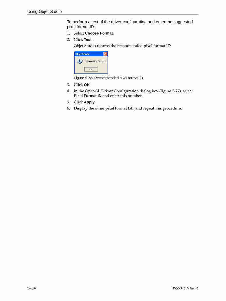
Using Objet Studio
5–54 DOC-34015 Rev. B
To perform a test of the driver configuration and enter the suggested pixel format ID:1. Select Choose Format. 2. Click Test.
Objet Studio returns the recommended pixel format ID.
Figure 5-78: Recommended pixel format ID
3. Click OK. 4. In the OpenGL Driver Configuration dialog box (figure 5‐77), select
Pixel Format ID and enter this number.5. Click Apply.6. Display the other pixel format tab, and repeat this procedure.

DOC-34015 Rev. B 5–55
Objet30 User Guide
Getting Additional Objet Studio AssistanceObjet Studio Help provides on‐screen instructions and information, as you work.
To view Objet Studio Help:On the standard toolbar, click and then click Objet Studio Help.
Figure 5-79: Help options
You can also view information on the following subjects:• Troubleshooting opens a list of error messages and their
explanations.• Check for Updates checks if you are using the latest Objet Studio
version.
Objet Studio Version, Material Module and Licensed FeaturesYou can view details of the Objet Studio version, the material module installed, and the features available with your license.
To view details of your Objet Studio installation:On the standard toolbar, click and then click About....
Figure 5-80: Displaying Objet Studio details
About Objet Studiotab
The About Objet Studio tab shows the Objet Studio version number and basic information about your computer.
Figure 5-81: About Objet Studio tab

Using Objet Studio
5–56 DOC-34015 Rev. B
Materials Moduletab
The Materials Module tab shows details of the material module installed.
Figure 5-82: Materials Module tab
• Module versionIf a Materials Module upgrade (patch) was installed, the new Materials Module version is displayed. If no patches were installed, the Module version is the same as the Objet Studio version.
• Module dateIf a Materials Module upgrade (patch) was installed, the date of its creation is displayed. If no patches were installed, the Module date is the date of the Objet Studio version.
• Module propertiesIf a Materials Module upgrade (patch) was installed, its description is displayed. If no patches were installed, “Default” is displayed.
Feature Licensetab
The Feature License tab shows the Objet Studio features available with your license.
Figure 5-83: Feature License tab
Click to expand the details for each feature.• Modes shows the printing modes available.• Materials shows model materials available.

DOC-34015 Rev. B 5–57
Objet30 User Guide
Monitoring and Managing Print JobsIn the Job Manager screen of Objet Studio, you monitor and manage jobs sent to the printer. There are a few differences between Objet Studio on client workstations and on the computer connected directly to the 3D printer—the server workstation.• Objet Studio installed on a client computer only displays the queue and
status for jobs sent to the 3D printer server from that computer, and it allows the user to edit only these jobs. Note: If there are several Objet printers on the local network, client computers can connect to any of them, but only one at a time.
• Objet Studio installed on the computer directly connected to a specific 3D printer (server), displays the queue and status for all jobs sent to that 3D printer by the server and by all client computers on the network. It also allows editing and manipulation of all jobs, and enables re‐sending previously‐printed jobs to the printer.
Job Manager Screen
The Job Manager screen on the client and server workstations looks identical. The only difference is that options only relevant to the server workstation are disabled for client installations.
Figure 5-84: Job Manager screen
The Job Manager screen is divided into panels:• Jobs Queue• Printing Progress• History• Available Resources• Material Consumption• Tray Preview• Waste
If Objet Studio is not connected to a printer (or printer server), you can prepare tray files for any Objet printer. Later, these files can be used by Objet Studio on the appropriate printer server.
Jobs Queue
Print History
Tray Preview
Materialsconsumption
Availableresources
Waste status
Job ManagerRibbon
Print Progress

Using Objet Studio
5–58 DOC-34015 Rev. B
Jobs Queue On the server, the Jobs Queue lists the last 15 jobs sent from client computers. On client workstations, the Jobs Queue lists jobs sent from that computer to the printer server. Information for each of the queued jobs is displayed, including the job status.
In addition, the following information is displayed:• Owner—the computer that sent the job.• Build Time—the estimated building time for the job.• Model Consumption—the amount of model material required to
complete the job, and the amount actually used till now.• Support Consumption—the amount of support material required to
complete the job, and the amount actually used till now.Printing Progress The Time panel shows printing times and the number of slices sent to the
printer.History The History panel shows information for the last 50 jobs and their final
status. You can drag a job from History to Jobs Queue to print the tray again.Available
ResourcesThe Available Resources panel contains graphic indicators that show the amount of available printing material remaining.
MaterialConsumption
• Actual—the amount of material used till now• Required—the amount of material still needed to finish the job
Tray Preview The Tray Preview panel displays the build tray view of the job selected in the Job Queue or the History list. On a server, you can open an enlarged preview window by clicking on the Tray Preview display (see “Extended Tray Preview” on page 67).
Waste If you move the mouse over the Waste display, the amount of waste in the container is displayed.
Status Meaning
Waiting Printing of this job has not started.
Building Printing of this job is in progress.
Stopped Printing of this job was interrupted. Printing can later be continued (Resume) or begun again (Restart).
Error Errors occurred during the printing of this job, and it was placed in the Jobs Queue again.
Editing This job is now being edited in Objet Studio.
Spooling The job file is being spooled in the printer.
Preprocessing The 3D printer is readying itself for printing: the cover locks, print heads warm up and are put in starting position, UV lamp is turned on, and the build tray level is adjusted.
On Schedule The job is scheduled to be printed at a specified time.

DOC-34015 Rev. B 5–59
Objet30 User Guide
Setting the Printer Connection
When an Objet 3D printer is installed, the server computer is connected to that printer. Normally, there should be no reason to change this connection. Occasionally, however, you may need to reset the connection, to connect the server to another printer, or to use Objet Studio in off‐line mode (without a printer connection).
To set (or change) the printer connection:1. On the Job Manager ribbon, in the 3D Printer group, click .2. In the Set Printer dialog box, click Connect.
Figure 5-85: Connecting to a printer (A)
3. Enter the computer name or its IP address, or click Browse to find and select it.
Figure 5-86: Connecting to a printer (B)
4. Click OK.When the connection is established, Objet Studio is configured to prepare print jobs for that printer.
Objet Studio is connected to the printer if you can see the material levels in the Job Manager screen (see figure 5-84 on page 57).

Using Objet Studio
5–60 DOC-34015 Rev. B
Off-line Mode You can use Objet Studio to prepare trays for printing in off‐line mode, on a remote computer or when the printer connection is not available. You also use off‐line mode to prepare trays for printing with other printers. In this case, if Objet Studio is currently connected to a printer, you must change to off‐line mode by removing this connection.
To disconnect Objet Studio from the printer:1. On the Job Manager ribbon, in the 3D Printer group, click .2. In the Set Printer dialog box, click Connect (see figure 5‐85).
Figure 5-87: Disconnecting Objet Studio from a printer (A)
3. In the Printer Connection dialog box, delete the computer name/IP address.
Figure 5-88: Disconnecting Objet Studio from a printer (B)
4. Click OK.“Unknown” appears in the printer‐name field.
5. Click OK.

DOC-34015 Rev. B 5–61
Objet30 User Guide
6. In the pop‐up message, confirm that you want to work in off‐line mode by clicking No.
Figure 5-89: Off-line message
When Objet Studio is in off‐line mode, you can configure it for preparing print jobs for different printers.
To change the Objet Studio off-line configuration:1. In the Set Printer dialog box, select a printer type.
Figure 5-90: Off-line printer selection
2. Click OK (not “Connect”).
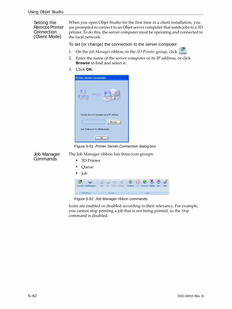
Using Objet Studio
5–62 DOC-34015 Rev. B
Setting the Remote Printer Connection (Client Mode)
When you open Objet Studio for the first time in a client installation, you are prompted to connect to an Objet server computer that sends jobs to a 3D printer. To do this, the server computer must be operating and connected to the local network.
To set (or change) the connection to the server-computer:
1. On the Job Manager ribbon, in the 3D Printer group, click .2. Enter the name of the server computer or its IP address, or click
Browse to find and select it.3. Click OK.
Figure 5-91: Printer Server Connection dialog box
Job Manager Commands
The Job Manager ribbon has three icon groups:• 3D Printer• Queue• Job
Figure 5-92: Job Manager ribbon commands
Icons are enabled or disabled according to their relevancy. For example, you cannot stop printing a job that is not being printed, so the Stop command is disabled.

DOC-34015 Rev. B 5–63
Objet30 User Guide
The following operations are available on the Job Manager ribbon:
Group Icon Purpose
3D Printer
Client: Sets the server connection. See “Setting the Remote Printer Connection (Client Mode)” on page 62.Server: Sets the printer connection. See “Setting the Printer Connection” on page 59.
Configures options for printer alerts. See “Configuring User Alerts” on page 65.
Queue Server: Moves a job to the head of the Jobs Queue.Client: Disabled.See “Jobs Queue” on page 58.
Server: Moves a job to a higher position in the Jobs Queue.Client: Disabled.See “Jobs Queue” on page 58.
Server: Moves a job to the bottom of the Jobs Queue. Client: Disabled.See “Jobs Queue” on page 58.
Server: Moves a job to a lower position in the Jobs Queue.Client: Disabled.See “Jobs Queue” on page 58.
Job Server: • For a job in the Jobs Queue—Prints it again (from the
beginning). • For a job in the History list—Moves it to the Jobs Queue
for printing.Client: Disabled.See “Restarting Jobs” on page 68.
Server: Stops a job in progress. Client: Disabled.
Server: Continues printing the current job from the point where printing stopped. Client: Disabled.See “Resuming Jobs” on page 68.
Removes the selected job from the queue.
Refreshes the image of the selected job in the Tray Preview display.
Opens the Tray Settings screen and displays the tray. For deleted jobs, this enables you to make changes before printing.

Using Objet Studio
5–64 DOC-34015 Rev. B
In addition to using ribbon command icons, you can use commands on context (pop‐up) toolbars and from the Job menu on the standard toolbar.
Figure 5-93: Icons on pop-up toolbar (server)
Figure 5-94: Icons on pop-up toolbar (client workstation)
Note: Most icons and menu commands are only enabled when a job is selected.
Figure 5-95: Job menu options (server)
Stop
Edit
Export packed job
Schedule
Resume
Restart
Delete
Edit
Delete
When you position the cursor over an item, a tooltip displays the name of the command.

DOC-34015 Rev. B 5–65
Objet30 User Guide
Configuring User Alerts
Objet Studio can alert you (and others) to the status of jobs sent to the server for printing. This is especially useful during long printing jobs, when the operator is away from the printer. The following events can be reported:• The level of model or support material is low.• The job was interrupted.• The job was completed successfully.To send e‐mail and SMS alerts, make sure that e‐mail software supporting MAPI is installed on the server computer. To send SMS alerts, the cellular phone service must support the transmission of e‐mail messages by SMS. Only the subject line of the e‐mail message is transmitted by SMS.
To configure Objet Studio to send notifications and alerts:
1. On the Job Manager ribbon, in the 3D Printer group, click .
Figure 5-96: Notifications dialog box (server)
Figure 5-97: Notifications dialog box (client workstation)
2. Set the desired reporting options.

Using Objet Studio
5–66 DOC-34015 Rev. B
3. Click Details.
Figure 5-98: Event selection for alerts
4. In the Reports Events dialog box, select the alert events and click OK.5. In the Notifications dialog box, click OK.
Printing the Tray
If there is a job in the Jobs Queue, it is sent automatically to the Objet printer—as long as it is on, there is a connection to the printer, and the printer is on line. Chapter 6 describes starting and operating the printer.
Additional Server Features
Objet Studio on the printer server includes the following additional features:• Extended Tray Preview• Editing Jobs• Restarting Jobs• Resuming Jobs• Scheduling Jobs• Exporting Jobs (objzf)• Modifying the Job Manager ScreenThese features are described on the following pages.

DOC-34015 Rev. B 5–67
Objet30 User Guide
Extended Tray PreviewIn this window, you can view the tray from different angles and magnifications without leaving the Job Manager screen. In addition to displaying the selected job in the Tray Preview pane, you can open an enlarged build tray window.
To display the build tray window:1. Select a job in the Jobs Queue or the History list.2. Click the Tray Preview pane.
Figure 5-99: Job Preview
• To change the tray magnification, turn the mouse wheel. • To view the tray from a different perspective, click the relevant icon.• To resize the window, drag its edge or corners.
If there are several objects on the build tray, you can exclude one or more from being printed, without actually deleting the object from the tray file.
To prevent the printing of an object on the build tray:1. Double‐click on the object you do not want to print.2. Display the Build tab.3. Select Exclude from Build.
Figure 5-100: Excluding a model from the build
4. Click Yes to confirm.On server computers, you can use Tray Preview to dynamically display objects as they are printed, layer by layer. This enables you to visually monitor printing progress on the computer screen.
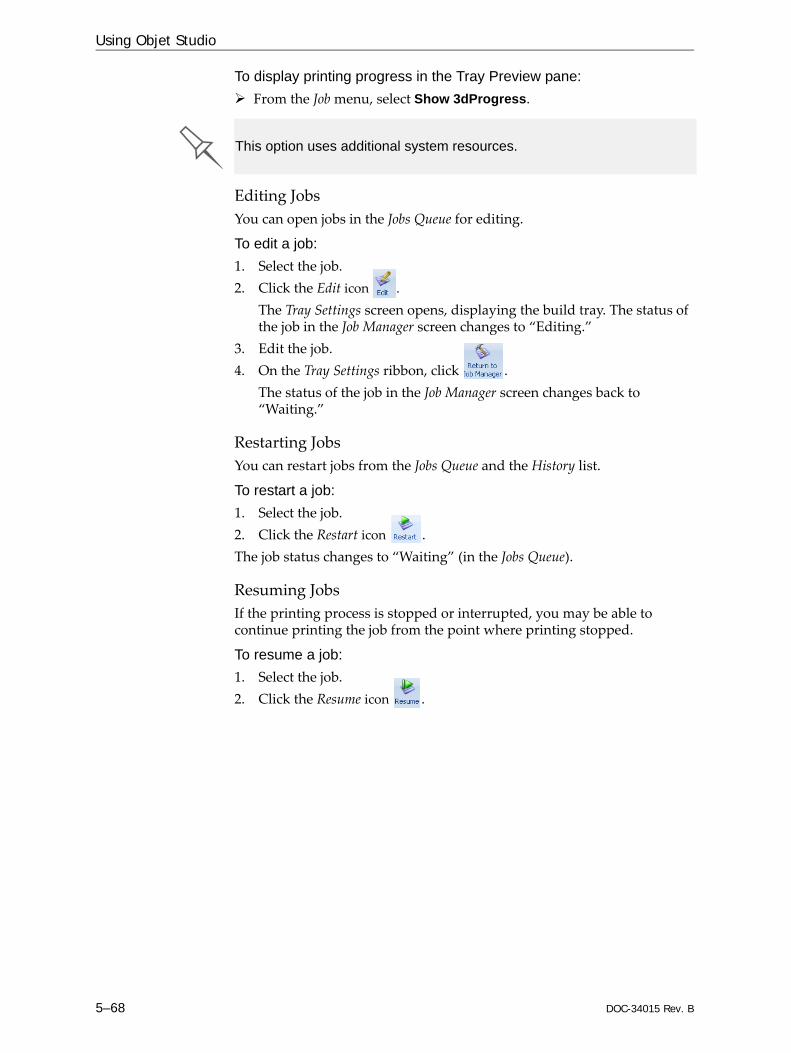
Using Objet Studio
5–68 DOC-34015 Rev. B
To display printing progress in the Tray Preview pane:From the Job menu, select Show 3dProgress.
Editing JobsYou can open jobs in the Jobs Queue for editing.
To edit a job:1. Select the job.2. Click the Edit icon .
The Tray Settings screen opens, displaying the build tray. The status of the job in the Job Manager screen changes to “Editing.”
3. Edit the job. 4. On the Tray Settings ribbon, click .
The status of the job in the Job Manager screen changes back to “Waiting.”
Restarting Jobs You can restart jobs from the Jobs Queue and the History list.
To restart a job:1. Select the job.2. Click the Restart icon .The job status changes to “Waiting” (in the Jobs Queue).
Resuming Jobs If the printing process is stopped or interrupted, you may be able to continue printing the job from the point where printing stopped.
To resume a job:1. Select the job.2. Click the Resume icon .
This option uses additional system resources.

DOC-34015 Rev. B 5–69
Objet30 User Guide
Scheduling JobsYou can schedule jobs to be printed at a future time. For example, you can configure Objet Studio to start long printing jobs in the late evening and early morning hours.
To schedule a job:1. Select a job in the Jobs Queue, and click on the pop‐up toolbar.2. In the Scheduler dialog box, set the Start Date and Start Time for the job.
Click on the Start Date arrow to open a calendar.
Figure 5-101: Scheduler with calendar displayed
3. Click OK.
Exporting Jobs (objzf)You can save print jobs as compressed files.
To export a print job:1. Select a job.2. On the pop‐up toolbar, click .3. In the Save As dialog box, select a folder.4. Click Save.
Modifying the Job Manager ScreenYou can change the size of the sections of the Job Manager screen, by dragging the panel edges. This applies to:• the Jobs Queue panel• the Time panel• the History panelSimilarly, you can change the way the screen area is divided between the main section (Jobs Queue/Time/History) and the panels on the right side of the screen.You can collapse (hide) the right panels (Available Resources/Material Consumption/Tray View) by clicking the top of the panel.• Click again to display the panel.
For an explanation of objzf files, see “Exporting and Importing Objet Build Trays” on page 45.


DOC-34015 Rev. B 6–1
Operating & Maintaining the Objet30 3D Printer
Starting the Objet30 Printer ............................................................... 2Loading Model and Support Cartridges.......................................... 4Producing Models ............................................................................... 6
Printer Interface Color Key.................................................................. 8Printing Indicators ................................................................................ 9
Resuming Production After Printing has Stopped....................... 10Changing the Model Material ......................................................... 12Keeping the Printer in Idle Mode ................................................... 18Shutting Down the Printer............................................................... 19
Shutdown Wizard ............................................................................... 19Material Flush/Fill Wizard................................................................. 21
Maintaining the Printer .................................................................... 24Routine Maintenance Schedule......................................................... 24Cleaning the Print Heads................................................................... 25Pattern Test........................................................................................... 27Improving Print Quality .................................................................... 28Cleaning and Replacing the Wiper................................................... 29Cleaning and Replacing the Roller Waste Collector ...................... 32Aligning the Print Heads ................................................................... 35Optimizing (Calibrating) Print Heads ............................................. 39Replacing Print Heads........................................................................ 46Testing and Calibrating the UV Lamp ............................................. 56Calibrating the Load Cells ................................................................. 59Replacing the Odor Filter................................................................... 61Replacing the UV Lamp..................................................................... 62Built‐in Tests......................................................................................... 66Replacing the Waste Container ......................................................... 68Cleaning the Exterior Panels ............................................................. 70Backing‐Up and Restoring Printer Settings .................................... 70ReInitiate Wizard ................................................................................ 70

Operating & Maintaining the Objet30 3D Printer
6–2 DOC-34015 Rev. B
Figure 6-1: The Objet30 3D Printer
Starting the Objet30 Printer
1. Turn on the main power switch, located at the back of the printer.
Figure 6-2: Main power switch and cable
The main power switch turns on the Objet printer, which includes —the built‐in computer.
2. After the computer boots, open the Remote Desktop Connection on the server (“host”) computer, by double‐clicking the Printer computer shortcut.
Printer cover
Materials drawer
Printer stand
CAUTION!• Do not attempt to operate the Objet printer before being trained by a
Stratasys customer-support representative.• Observe all safety warnings and follow the safety guidelines described in
chapter 2.

DOC-34015 Rev. B 6–3
Objet30 User Guide
3. Launch the printer‐control application:• On the printer‐computer desktop, double‐click the Objet printer
icon.or—• From the Start menu, select (All) Programs > Objet > Objet.
The Objet printer interface screen opens (see figure 6‐3). All monitoring and controlling of the printer is done from this interface.
Figure 6-3: Objet30 interface
A HASP plug containing a valid product activation key is required on the printer computer. This is installed at the factory or during printer upgrade. If the application does not open and a HASP message appears, contact your dealer or Stratasys Customer Support.
Printer mode
Support materialcartridges
Display toggle button
Stop button
Model material cartridges
Current activity
Online/offline button
The time zone on the printer computer is factory-set and it cannot be changed. Similarly, the computer’s clock cannot be configured to automatically change the time for different seasons of the year. If necessary, you can change the displayed time manually, but do so only when the printer is idle.

Operating & Maintaining the Objet30 3D Printer
6–4 DOC-34015 Rev. B
Loading Model and Support CartridgesObjet30 printers use two cartridges of Model material and two cartridges of Support material, each weighing one kilogram when full. A graphical representation of the cartridges loaded and their current weight appears in the printer interface (see figure 6‐3).
Note: The printer-control interface displays the type and weight of the material cartridges loaded only if the materials drawer is closed.
Important: If you need to replace the Model material currently installed with another type, see “Changing the Model Material” on page 6‐12. Otherwise, make sure to replace the Model cartridge with one containing the same type of material.
To load Model and Support material:1. On the front of the printer (see figure 6‐1), push the materials drawer to
release it and pull it open.2. If you are replacing a cartridge, remove the old one by pulling it
straight up.3. Load Model and Support cartridges into their respective
compartments (see figure 6‐4).
Figure 6-4: Materials drawer
4. Close the materials drawer.
The printer uses RFID technology to automatically identify cartridges of printing material. For this purpose, an RFID module is part of the printer hardware. Tampering with this module will render the printer inoperable and may void Stratasys warranties and service contracts.
Waste
Model 1
Model 2
Support 1
Support 2

DOC-34015 Rev. B 6–5
Objet30 User Guide
5. Check the printer interface to make sure that the new cartridge is detected and that its weight is displayed (see figure 6‐3).
Tips about replacing cartridges:
• You can replace material cartridges either before or during printing. If you do so while printing, make sure to load the new cartridge and close the materials drawer within three minutes. This ensures that the print job is not interrupted. (When the drawer is open, the cartridges are not displayed in the printer interface.)
• If printing stops for an extended time before you replace a material cartridge, the printer may go into Standby or Idle mode. If this happens, see “Resuming Production After Printing has Stopped” on page 10.
• You can replace partially used cartridges to avoid the need for replacing them during printing. However, repeated removal and installation of a cartridge may cause the material in it to leak. Therefore, it is recommended that you limit the re-installation of used cartridges.
• You can load partially used cartridges, as long as they contain more than 100 grams of material.

Operating & Maintaining the Objet30 3D Printer
6–6 DOC-34015 Rev. B
Producing ModelsThe Objet30 printer produces models by printing tray files prepared in the Objet Studio application and sent to the printer from there. For information about preparing model files for printing, see “Using Objet Studio” or Objet Studio Help.The Objet30 printer is capable of printing models with the following maximum dimensions:• With glossy finish—
X‐axis: 294.00 mm (11.57 inches)Y‐axis: 192.00 mm (7.55 inches)Z‐axis: 148.60 mm (5.85 inches)*
* OrthoDesk printers—100.0 mm (3.94 inches)• With matte finish—
X‐axis: 293.00 mm (11.53 inches)Y‐axis: 191.00 mm (7.52 inches)Z‐axis: 148.30 mm (5.83 inches)*
* OrthoDesk printers—97.9 mm (3.85 inches)
To prepare the printer for producing models:1. Make sure that the build tray in the printer is empty and clean. If not,
remove cured material with the scraper, and clean the tray thoroughly with a wet cleaning cloth.
2. Make sure that there is sufficient Model and Support material loaded, as indicated in the printer interface (see figure 6‐3). You may want to replace the cartridges of Model and Support material currently loaded in the printer to avoid the need for replacing them during printing.
Before beginning to produce models, it is recommended that you check the current printing quality of the print heads by performing a pattern test (see “Pattern Test” on page 27).
CAUTION: Use protective gloves when cleaning the build tray, and be careful of the sharp edges of the scraper blade.
For installing material cartridges and replacing empty ones, see “Loading Model and Support Cartridges” on page 6‐4.

DOC-34015 Rev. B 6–7
Objet30 User Guide
3. On the printer interface, click the red button to switch the printer to online mode.The color of the button changes from red to green (see figure 6‐7). If there is a job in the Job Manager queue, it is sent to the printer.
In the printer interface, the printer mode changes from Idle to Pre‐print, as the printer’s components prepare themselves for production: • The print block is heated.• If more than 48 hours have passed since the last print job, the printing
materials in the print heads are flushed and replaced, to ensure quality printing. (This step adds 7 to 14 minutes to the Pre‐print cycle, and it is displayed in the printer interface.)
Figure 6-5: ReInitiate process during the Pre-Print cycle
• The UV lamp is powered and it warms up.When printing begins, Objet Studio sends seven slices to the printer. This is the standard buffer between Objet Studio and the printer. As each slice is printed, another slice is sent to the printer.Depending on the size of the model(s) to be produced, printing can take between several hours to several days. As long as there is enough Model and Support material in the supply cartridges, printing proceeds automatically until the job is finished.
The Objet printer uses one Model‐material cartridge and one Support‐material cartridge to produce models. When four cartridges are loaded in the printer, two of them are reserve, or standby, cartridges. By default, the printer first uses the cartridges with the least material in them.
The active cartridges are blue in the printer interface. When the weight of a cartridge drops below 100 grams, the remaining material displayed in the printer interface is red. The printer then alternates the pumping of material between the heavier and the almost‐empty cartridge. This is indicated in the printer interface by an hour‐glass icon. (See figure 6‐8 on page 9.)When a cartridge is completely empty, a trash icon is displayed.
Figure 6-6: Empty cartridge indicator
During printing, the server computer must remain on and it must communicate with the Objet printer. Do not log-off Windows until printing is finished.
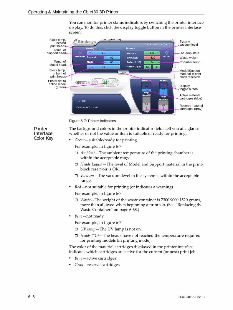
Operating & Maintaining the Objet30 3D Printer
6–8 DOC-34015 Rev. B
You can monitor printer status indicators by switching the printer interface display. To do this, click the display toggle button in the printer interface screen.
Figure 6-7: Printer indicators
Printer Interface Color Key
The background colors in the printer indicator fields tell you at a glance whether or not the value or item is suitable or ready for printing. • Green—suitable/ready for printing
For example, in figure 6‐7:Ambient—The ambient temperature of the printing chamber is within the acceptable range.Heads Liquid—The level of Model and Support material in the print‐block reservoir is OK.Vacuum—The vacuum level in the system is within the acceptable range.
• Red—not suitable for printing (or indicates a warning)For example, in figure 6‐7: Waste—The weight of the waste container is 7300 9000 1520 grams, more than allowed when beginning a print job. (See “Replacing the Waste Container” on page 6‐68.)
• Blue—not readyFor example, in figure 6‐7:UV lamp—The UV lamp is not on.Heads (°C)—The heads have not reached the temperature required for printing models (in printing mode).
The color of the material cartridges displayed in the printer interface indicates which cartridges are active for the current (or next) print job.• Blue—active cartridges• Gray—reserve cartridges
Block temp.in front of
print heads
Block temp.behind
print heads
Display toggle button
Temp. ofSupport head
Printer set toonline mode
(green)
System vacuum level
Chamber temp.
Model/Support material in print- block reservoir
Temp. ofModel head
Waste weightUV lamp state
Active material cartridges (blue)
Reserve material cartridges (gray)
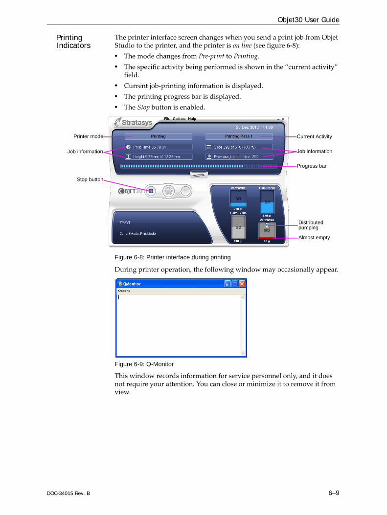
DOC-34015 Rev. B 6–9
Objet30 User Guide
Printing Indicators
The printer interface screen changes when you send a print job from Objet Studio to the printer, and the printer is on line (see figure 6‐8):• The mode changes from Pre‐print to Printing. • The specific activity being performed is shown in the “current activity”
field. • Current job‐printing information is displayed.• The printing progress bar is displayed.• The Stop button is enabled.
Figure 6-8: Printer interface during printing
During printer operation, the following window may occasionally appear.
Figure 6-9: Q-Monitor
This window records information for service personnel only, and it does not require your attention. You can close or minimize it to remove it from view.
Progress bar
Stop button
Printer mode
Job information
Current Activity
Job information
Distributed pumping
Almost empty

Operating & Maintaining the Objet30 3D Printer
6–10 DOC-34015 Rev. B
Resuming Production After Printing has StoppedIf the printing process is interrupted, Objet Studio stops sending slices to the printer. This can happen, for example, if the printing material runs out in the middle of a print job, and you don’t replace the empty cartridge immediately. After the printer changes to Standby or Idle mode, you need to resume printing from the Job Manager screen of Objet Studio.
To continue printing the model:1. If the printer is in offline mode, switch it to online mode by clicking the
red button at the bottom of the printer interface (see figure 6‐3 on page 3).The button changes from red to green (see figure 6‐7 on page 8).
2. If you don’t know why printing has stopped, make sure that the connection between the printer and the server computer is active.
3. In the Job Manager screen of Objet Studio, click the Resume icon .4. In the Continue from Slice dialog box that appears, confirm the slice
number, after checking the printer interface.
Figure 6-10: Printer interface after interrupted printing
Figure 6-11: Continue from Slice confirmation in Objet Studio (Job Manager screen)
5. If, for any reason, the correct number does not appear in the dialog box, enter the number and click OK.
After printing stops, the printer goes into Standby mode, when heating of print heads is reduced. About 20 minutes later, the printer goes into Idle mode, when heating of print heads is stopped.
Printer mode
Last slice printed

DOC-34015 Rev. B 6–11
Objet30 User Guide
You cannot continue printing the model if:• The number of the last slice printed does not appear in the printer
interface, even if the server computer displays the Continue from Slice confirmation dialog box.
• There was a relatively long interruption in printing, even if the “last slice” and “continue from slice” indicators are correct. The part of the model already printed may deform or shrink, and there might be a visible difference between it and the newly printed part. The effects of a printing stoppage on a model depend on the model size and structure, Model material used, ambient temperature and the length of the stoppage.
If you cannot continue printing: 1. Cancel the print job in the Job Manager screen.2. Remove the partially printed model from the build tray. 3. Restart the job from the Job Manager screen (in Objet Studio).
You can stop printing from either the printer interface or from the Job Manager screen of Objet Studio. Resuming printing is only available from the Job Manager screen.

Operating & Maintaining the Objet30 3D Printer
6–12 DOC-34015 Rev. B
Changing the Model MaterialBefore producing models using a different type of Model material than is currently installed, run the Material Replacement Wizard to flush the print block and feed tubes.
To replace the Model material:1. Start the Material Replacement Wizard from the Options menu.
Figure 6-12: Starting the Material Replacement Wizard
2. In the opening screen, click Next.3. If the printer cover is not closed, a screen appears, prompting you to
close the cover. Confirm that it is closed and click Next.4. When the Cartridge Loading screen appears, indicate whether or not
replacement cartridges have been loaded.
Figure 6-13: Replacement-cartridge status
You should carefully plan printing models with different Model materials to avoid unnecessary waste of the materials currently loaded. The amount of material flushed depends on the flushing cycle chosen and if you are replacing one or both Model cartridges. For details, see page 14.

DOC-34015 Rev. B 6–13
Objet30 User Guide
5. Click Next.• If the replacement cartridges are already loaded in the materials
drawer, a screen appears, showing the materials currently in the system and the material cartridges in the drawer.
Figure 6-14: Material Replacement Summary screen
After reviewing this screen, click Next and continue with step 8.• If the replacement cartridges are not loaded in the materials drawer,
the Compartment Selection screen appears.
Figure 6-15: Compartment Selection screen
6. Select the cartridge(s) you want to replace, and click Next.

Operating & Maintaining the Objet30 3D Printer
6–14 DOC-34015 Rev. B
7. From the drop‐down menu, choose the material you want to install, and click Next.
Figure 6-16: Material Selection screen
8. In the Flushing Options screen, choose the appropriate cycle for the Model material you want to install.
Figure 6-17: Flushing Options screen
• Economy. During this cycle, which takes about 25 minutes, the pump purges the Model material from the print block, then flushes the system with the new material.Since traces of the previous material may be present in the first models printed with the new material, this cycle is usually acceptable when replacing a light‐colored Model material with a darker material (such as VeroBlack™), or if the exact color of the printed models is unimportant. However, this cycle ensures that models will have the mechanical properties of the new material.The amount of material flushed during this cycle is—¤ 65 grams (± 10%) when replacing one cartridge¤ 110 grams (± 10%) when replacing two cartridges
The Model materials available for selection depend on your printer type and license.

DOC-34015 Rev. B 6–15
Objet30 User Guide
• High‐performance. During this cycle, which takes about 60 minutes, the wizard cleans the feed tubes and print block more thoroughly, compared to the Economy cycle, by flushing the system with more material.This cycle ensures that models will have the color (and the mechanical properties) of the new material, when replacing a dark‐colored material (such as VeroBlack) with a lighter‐colored material.The amount of material flushed during this cycle is—¤ 300 grams (± 10%) when replacing one cartridge¤ 450 grams (± 10%) when replacing two cartridges
9. Click Next, and take note of the warning screen.
Figure 6-18: Material Replacement warning screen
10. Click Next.• If the replacement cartridges are already loaded in the materials
drawer, the wizard checks that there is sufficient material to complete the procedure. Continue with step 13.
• If the replacement cartridges are not loaded in the materials drawer, the wizard prompts you to remove the cartridge(s) from the drawer. Continue with step 11.
Once you start this procedure, you must complete it before you can produce models with the Objet printer. To perform the procedure at another time, click Cancel. If you continue (by clicking Next) and you do not complete the procedure, you must start the Material Replacement Wizard again before producing models.
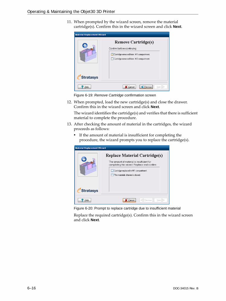
Operating & Maintaining the Objet30 3D Printer
6–16 DOC-34015 Rev. B
11. When prompted by the wizard screen, remove the material cartridge(s). Confirm this in the wizard screen and click Next.
Figure 6-19: Remove Cartridge confirmation screen
12. When prompted, load the new cartridge(s) and close the drawer. Confirm this in the wizard screen and click Next.The wizard identifies the cartridge(s) and verifies that there is sufficient material to complete the procedure.
13. After checking the amount of material in the cartridges, the wizard proceeds as follows:• If the amount of material is insufficient for completing the
procedure, the wizard prompts you to replace the cartridge(s).
Figure 6-20: Prompt to replace cartridge due to insufficient material
Replace the required cartridge(s). Confirm this in the wizard screen and click Next.

DOC-34015 Rev. B 6–17
Objet30 User Guide
• If the amount of material is sufficient for completing the procedure, the printer purges the current material from the system, then flushes the system and fills the print heads with the new material.
Figure 6-21: Material replacement: filling heads with new material
14. Click Done to close the wizard.The printer‐control application is automatically updated, and the interface displays the new material(s). The Objet Studio application (on the printer‐server computer) is also updated and displays the new material(s).
15. Inspect the area around the purge unit and clean it, if necessary.
CAUTION: Dispose of all material cartridges in accordance with all applicable laws and regulations. If necessary, the cartridges can be disassembled for recycling. If this is done, protect the person handling the cartridges from direct exposure to uncured resins.

Operating & Maintaining the Objet30 3D Printer
6–18 DOC-34015 Rev. B
Keeping the Printer in Idle ModeBetween printing jobs, the Objet30 printer can be kept on for up to one week. If the printer will not be used for more than a week, use the Shutdown Wizard to automatically perform the procedures that must be done before turning off the printer (see “Shutting Down the Printer,” below).When the printer stops producing models, the printer software automatically reduces the temperature of the print heads as follows:
Note: The printer mode is indicated in the green field on the left of the interface (see figures 6-3, 6-7 and 6-8 on pages 3, 8 and 9).
If, after printing a job, you know that the printer will not be used for 20 minutes or more, you can immediately turn off the heating of the print heads by putting the printer into Idle mode.
To put the printer into Idle mode:From the File menu (in the printer interface) click Exit.
Note: The printer remains in Idle mode until you open the Objet printer application and begin printing again.
Time after printing Mode Change in heating of print heads
first 15 minutes Standby 1 none
next 5 minutes Standby 2 heating reduced (to room temp.)
after 20 minutes Idle heating stopped
When the printer is in Idle mode, do not turn it off. It can remain in this mode—with the cover closed—for up to a week. For longer periods, shut down the printer by running the Shutdown Wizard (see below).

DOC-34015 Rev. B 6–19
Objet30 User Guide
Shutting Down the PrinterYou only need to shut down the Objet printer if it will not be used for a week or more. Otherwise, the printer can remain on, in Idle mode.
To properly shut down, the printer needs to perform several processes. Do not attempt to shut down the printer by simply closing the computer interface (the printer‐control application), and never disconnect power to the printer before completing the Shutdown Wizard.• Shutdown for Less Than One Week
Before shutting down the printer or the printer computer for less than one week, run the Shutdown Wizard. This wizard clears the print heads of printing materials before shutdown.
• Shutdown for One Week or MoreBefore shutting down the printer or the printer computer for one week or more, first run the Material Flush/Fill Wizard. This wizard replaces printing materials in the print block with cleaning fluid.Note: After preparing the printer with the Material Flush/Fill Wizard, you must run it again before printing models, this time to replace the cleaning fluid in the print block with printing materials.)
Shutdown Wizard
To run the Shutdown Wizard:1. Select Shutdown Wizard from the Options menu, or press F8.
Figure 6-22: Shutdown Wizard, opening screen
2. Select Run wizard unattended, unless you want more control over the shutdown process.Note: If you select Run wizard unattended, the wizard automatically turns off the printer computer at the end of the process.
3. Click Next.The options in the following screens are enabled only if you selected Run wizard manually in the opening wizard screen.
The Shutdown process flushes printing materials from printer components. To avoid flushing out valuable material, make sure to print models at least once a week. Many printer operators use this opportunity to print customer samples or test models.

Operating & Maintaining the Objet30 3D Printer
6–20 DOC-34015 Rev. B
4. In the next screen, indicate whether or not the tray is empty and click Next.
Figure 6-23: Tray status screen
The shutdown procedure begins.
Figure 6-24: Shutdown progress screen
The shutdown procedure may take up to 10 minutes while the following tasks are performed:a. The print block returns to its starting point on all axes.b. The print heads are heated.c. The print heads are cleared of any remaining material.After these tasks are completed, the final wizard screen appears, in which you choose whether or not to shut down the computer in the Objet printer at this time.
Figure 6-25: Computer Shutdown confirmation screen

DOC-34015 Rev. B 6–21
Objet30 User Guide
5. When completely shutting down the Objet printer and turning the power off, select Yes and click Next.
6. After the printer computer shuts down, turn off the main power switch at the back of the printer (see figure 6‐2 on page 2).
Material Flush/Fill Wizard
Use this wizard to prepare the printer for a shutdown of more than one week, and to restore the printer to working condition.• To prepare the printer for an extended shutdown, the wizard drains
printing materials from the print heads, then flushes the system with cleaning fluid. This process takes about 60 minutes.For this procedure, you need to load four (4) cleaning‐fluid cartridges in the materials drawer.
• To restore the printer to working condition, the wizard fills the system with printing materials. This process takes about 30 minutes.For this procedure, you need to load two (2) cartridges of Model material and two (2) cartridges of Support material.
To run the Material Flush/Fill Wizard:1. Start Material Flush/Fill Wizard from the Options menu.2. In the opening screen, click Next.
Figure 6-26: Wizard procedure selection
3. Select the required procedure, and click Next.Note: Before continuing, make sure the required cartridges of material are available for the procedure selected.
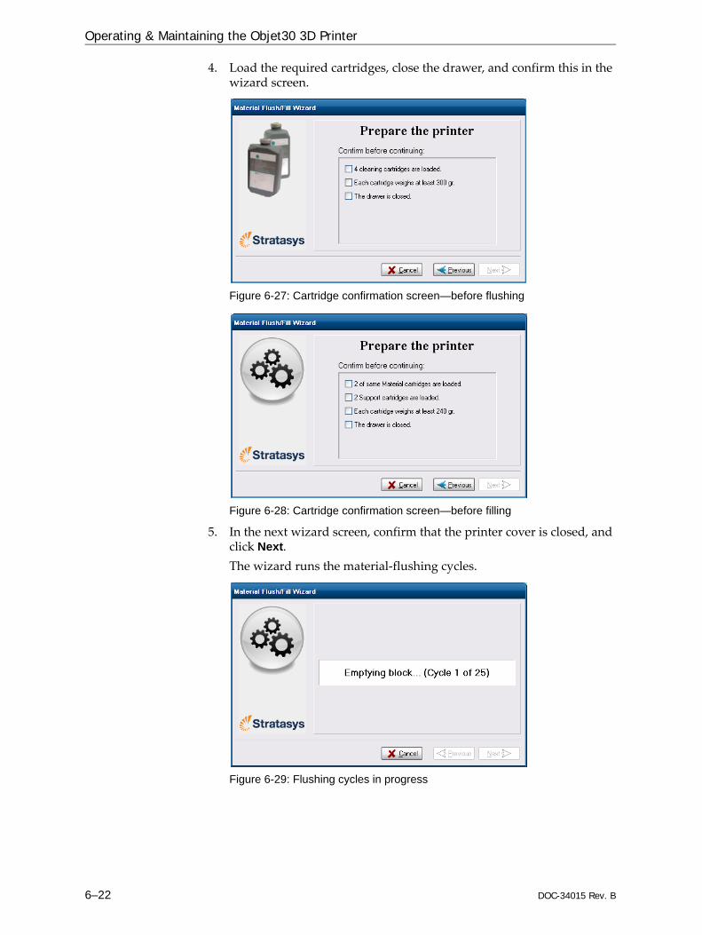
Operating & Maintaining the Objet30 3D Printer
6–22 DOC-34015 Rev. B
4. Load the required cartridges, close the drawer, and confirm this in the wizard screen.
Figure 6-27: Cartridge confirmation screen—before flushing
Figure 6-28: Cartridge confirmation screen—before filling
5. In the next wizard screen, confirm that the printer cover is closed, and click Next.The wizard runs the material‐flushing cycles.
Figure 6-29: Flushing cycles in progress

DOC-34015 Rev. B 6–23
Objet30 User Guide
6. If cleaning‐fluid cartridges are loaded in the printer, the wizard prompts you to remove them. Confirm this in the wizard screen, and click Next.
Figure 6-30: Final wizard screen
After preparing the printer for an extended shutdown period with this wizard, you should close the printer-control application and Windows, and then turn off the printer.
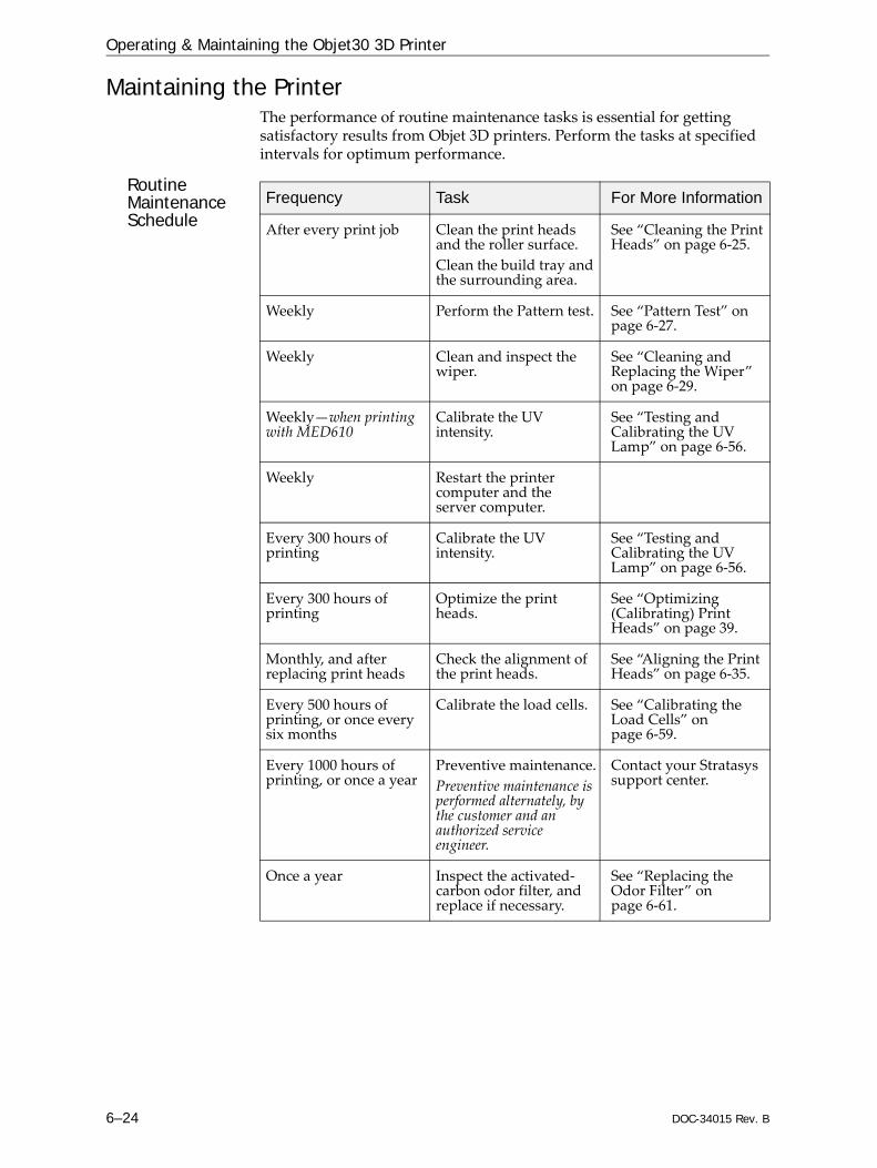
Operating & Maintaining the Objet30 3D Printer
6–24 DOC-34015 Rev. B
Maintaining the PrinterThe performance of routine maintenance tasks is essential for getting satisfactory results from Objet 3D printers. Perform the tasks at specified intervals for optimum performance.
Routine Maintenance Schedule
Frequency Task For More Information
After every print job Clean the print heads and the roller surface.Clean the build tray and the surrounding area.
See “Cleaning the Print Heads” on page 6‐25.
Weekly Perform the Pattern test. See “Pattern Test” on page 6‐27.
Weekly Clean and inspect the wiper.
See “Cleaning and Replacing the Wiper” on page 6‐29.
Weekly—when printing with MED610
Calibrate the UV intensity.
See “Testing and Calibrating the UV Lamp” on page 6‐56.
Weekly Restart the printer computer and the server computer.
Every 300 hours of printing
Calibrate the UV intensity.
See “Testing and Calibrating the UV Lamp” on page 6‐56.
Every 300 hours of printing
Optimize the print heads.
See “Optimizing (Calibrating) Print Heads” on page 39.
Monthly, and after replacing print heads
Check the alignment of the print heads.
See “Aligning the Print Heads” on page 6‐35.
Every 500 hours of printing, or once every six months
Calibrate the load cells. See “Calibrating the Load Cells” on page 6‐59.
Every 1000 hours of printing, or once a year
Preventive maintenance.Preventive maintenance is performed alternately, by the customer and an authorized service engineer.
Contact your Stratasys support center.
Once a year Inspect the activated‐carbon odor filter, and replace if necessary.
See “Replacing the Odor Filter” on page 6‐61.
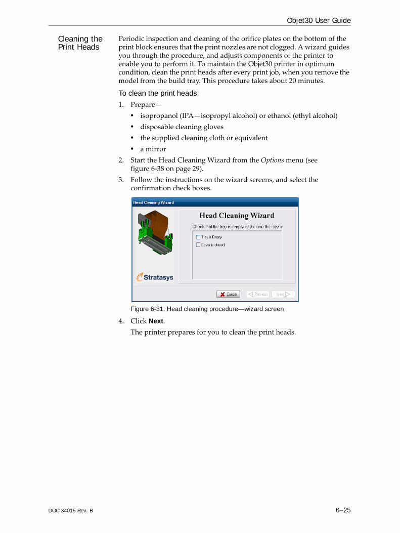
DOC-34015 Rev. B 6–25
Objet30 User Guide
Cleaning the Print Heads
Periodic inspection and cleaning of the orifice plates on the bottom of the print block ensures that the print nozzles are not clogged. A wizard guides you through the procedure, and adjusts components of the printer to enable you to perform it. To maintain the Objet30 printer in optimum condition, clean the print heads after every print job, when you remove the model from the build tray. This procedure takes about 20 minutes.
To clean the print heads:1. Prepare—
• isopropanol (IPA—isopropyl alcohol) or ethanol (ethyl alcohol)• disposable cleaning gloves• the supplied cleaning cloth or equivalent• a mirror
2. Start the Head Cleaning Wizard from the Options menu (see figure 6‐38 on page 29).
3. Follow the instructions on the wizard screens, and select the confirmation check boxes.
Figure 6-31: Head cleaning procedure—wizard screen
4. Click Next. The printer prepares for you to clean the print heads.
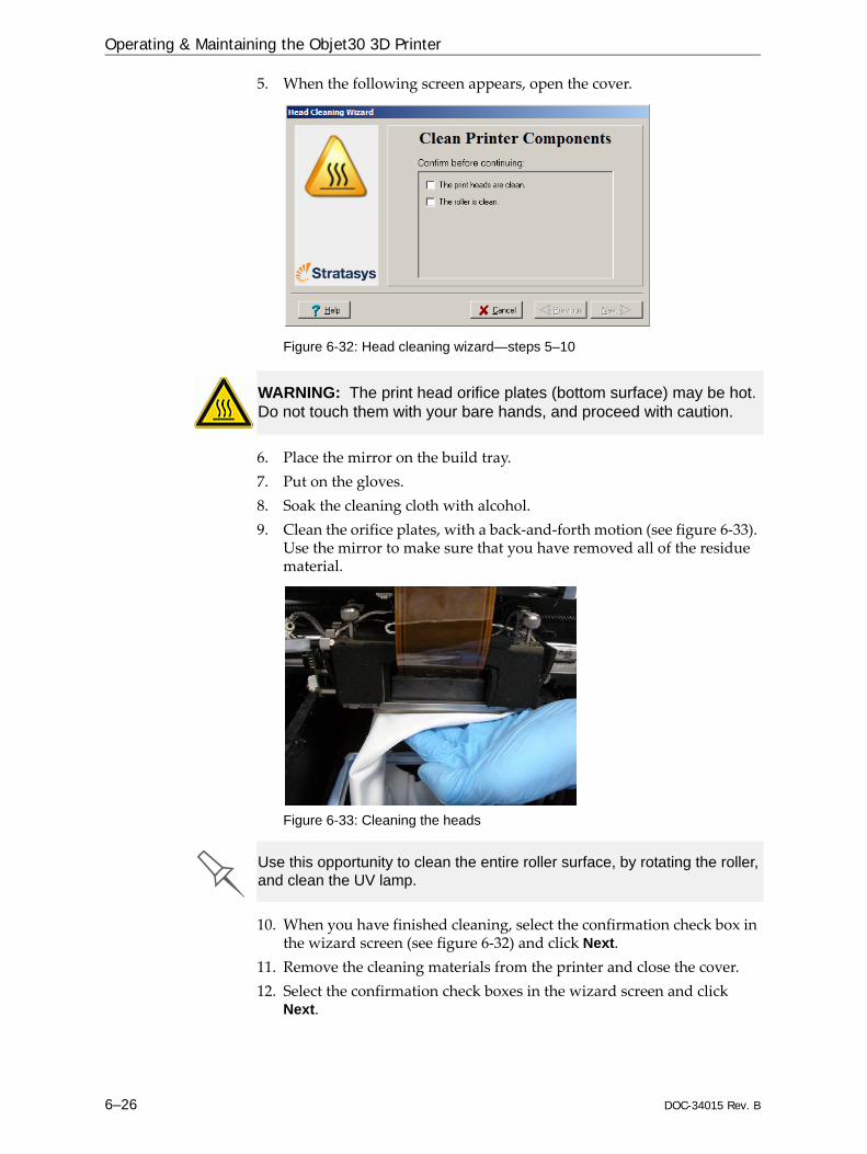
Operating & Maintaining the Objet30 3D Printer
6–26 DOC-34015 Rev. B
5. When the following screen appears, open the cover.
Figure 6-32: Head cleaning wizard—steps 5–10
6. Place the mirror on the build tray.7. Put on the gloves.8. Soak the cleaning cloth with alcohol.9. Clean the orifice plates, with a back‐and‐forth motion (see figure 6‐33).
Use the mirror to make sure that you have removed all of the residue material.
Figure 6-33: Cleaning the heads
10. When you have finished cleaning, select the confirmation check box in the wizard screen (see figure 6‐32) and click Next.
11. Remove the cleaning materials from the printer and close the cover. 12. Select the confirmation check boxes in the wizard screen and click
Next.
WARNING: The print head orifice plates (bottom surface) may be hot. Do not touch them with your bare hands, and proceed with caution.
Use this opportunity to clean the entire roller surface, by rotating the roller, and clean the UV lamp.

DOC-34015 Rev. B 6–27
Objet30 User Guide
The head‐purge cycle begins. When this is complete, the final wizard screen appears.
Figure 6-34: Head-cleaning wizard—final screen
13. Click Done to close the wizard.
Pattern Test The pattern test is the basic verification of the printer’s ability to produce quality models, since it demonstrates the condition of the nozzles in the print heads. Make sure, therefore, that you perform this test weekly, and whenever you suspect a printing problem.
To perform the pattern test:1. Make sure that the build tray is empty.2. Prepare a sheet of pink paper, approximately 21 × 14 centimeters in
size (8.5 × 5.5 inches)—half of the standard A‐4 or Letter size.3. In the printer, tape the pink paper to the center of the build tray.4. Press F3, or open the Options menu and select Pattern Test.
Figure 6-35: Pattern Test confirmation
5. In the following dialog box, click OK to confirm that the paper is in place on the build tray.
Figure 6-36: Confirmation before printing on test paper

Operating & Maintaining the Objet30 3D Printer
6–28 DOC-34015 Rev. B
The printer prints a series of lines on the test paper (see next figure).
Figure 6-37: Sample Pattern Test
6. Carefully inspect the test paper to see if there are missing lines. Too many missing lines, especially if they are in the same area, indicates that the quality of printing when producing models will be poor. If this is the case, see “Improving Print Quality,” below.Note: Acceptable model quality is subjective, and depends on the type and scale (size) of the models produced. As a rule, however, if two consecutive lines are missing, or if there are more than 10 lines missing in either column, the model quality is usually unacceptable.
Improving Print Quality
If you suspect that print quality is poor, perform the pattern test (see “Pattern Test”). If the results are poor, use the following procedure to improve print quality.
If the results of the last pattern test are poor:1. From the Options menu, select Purge Sequence, or press F4.2. In the confirmation dialog box, click Yes.
The print heads are purged of Model and Support material, and the wiper removes excess material from them.
3. Repeat the purge sequence.4. Perform the pattern test.
If the results of the pattern test are still poor:1. Manually clean the print heads (see “Cleaning the Print Heads” on
page 6‐25).2. Perform the purge sequence.3. Perform the pattern test.
If the results of the pattern test are still poor:1. Carefully clean the print heads again, making sure there is no residue
left on them.2. Perform the purge sequence.
Lines printed by Model-material print head
Lines printed bySupport-material
print head
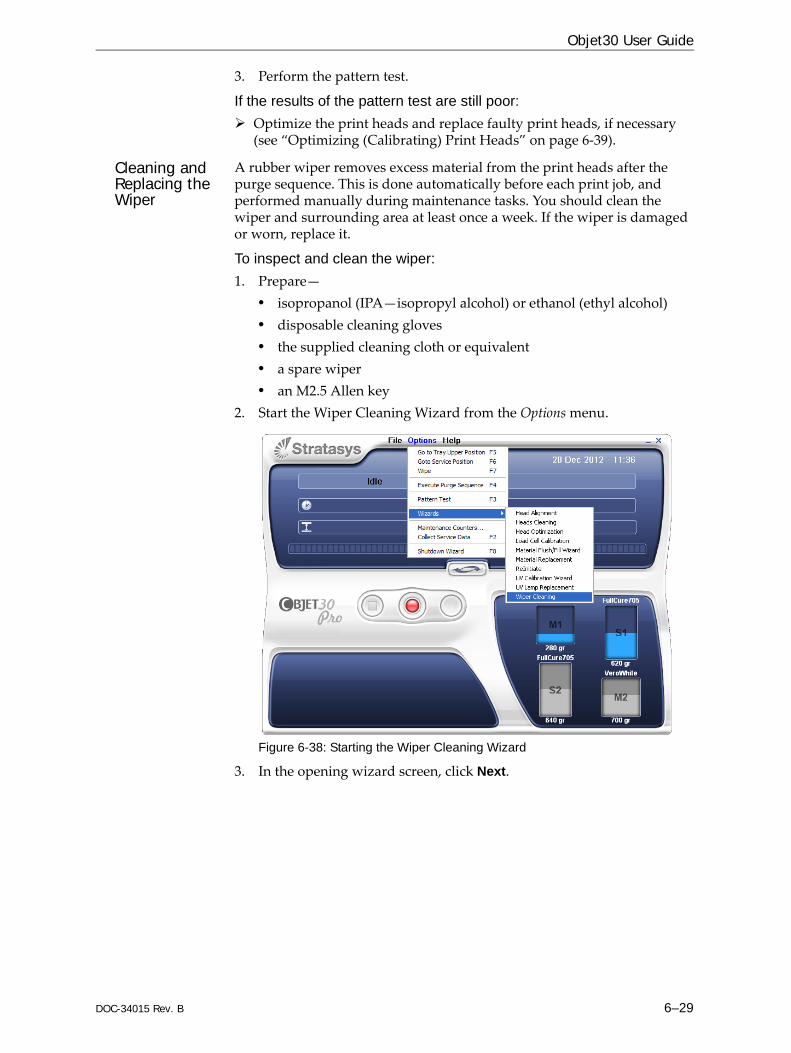
DOC-34015 Rev. B 6–29
Objet30 User Guide
3. Perform the pattern test.
If the results of the pattern test are still poor:Optimize the print heads and replace faulty print heads, if necessary (see “Optimizing (Calibrating) Print Heads” on page 6‐39).
Cleaning and Replacing the Wiper
A rubber wiper removes excess material from the print heads after the purge sequence. This is done automatically before each print job, and performed manually during maintenance tasks. You should clean the wiper and surrounding area at least once a week. If the wiper is damaged or worn, replace it.
To inspect and clean the wiper:1. Prepare—
• isopropanol (IPA—isopropyl alcohol) or ethanol (ethyl alcohol)• disposable cleaning gloves• the supplied cleaning cloth or equivalent• a spare wiper• an M2.5 Allen key
2. Start the Wiper Cleaning Wizard from the Options menu.
Figure 6-38: Starting the Wiper Cleaning Wizard
3. In the opening wizard screen, click Next.

Operating & Maintaining the Objet30 3D Printer
6–30 DOC-34015 Rev. B
4. Make sure that the build tray is empty, and close the printer cover.Confirm this in the wizard screen and click Next.
Figure 6-39: Wiper Cleaning procedure—step 4
5. When the following screen appears, open the cover.
Figure 6-40: Wiper Cleaning Wizard during steps 6–9
6. Put on the cleaning gloves.7. Using a generous amount of alcohol on the cleaning cloth, remove any
material remaining on the wiper and the surrounding area.

DOC-34015 Rev. B 6–31
Objet30 User Guide
8. Inspect the wiper. If the wiper is scratched, torn or worn, or if you cannot clean it completely, replace it.a. With the M3 Allen key, loosen (but do not remove) the screw
securing the wiper.
Figure 7: Wiper and excess-material drain
b. Grasp the wiper unit and remove it.Note:Do not remove the grease.
c. Insert the new wiper, making sure that it is level, and tighten the securing screw.
9. In the wizard screen (see figure 6‐40), confirm that the wiper blade is clean, and click Next.
10. Remove all tools and cleaning materials from the printer, and close the cover.
11. Confirm this in the wizard screen, and click Next.
Figure 6-41: Confirmation screen
12. Click Done to close the wizard.
Wiper
Securing screw
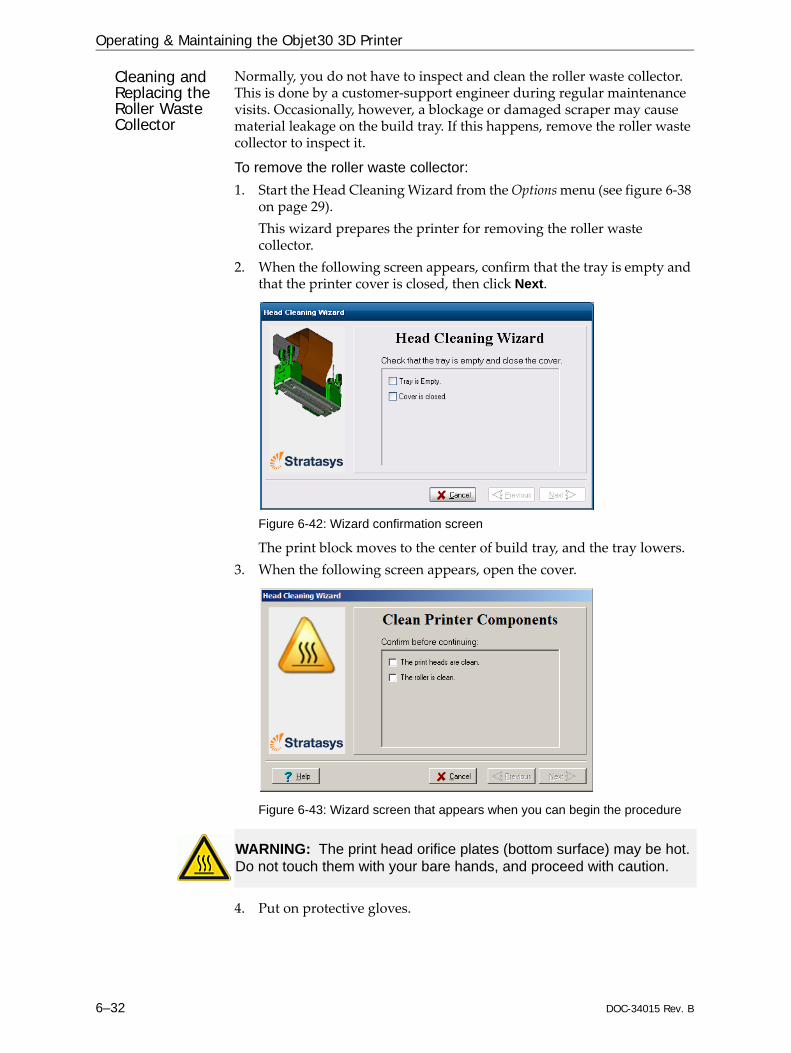
Operating & Maintaining the Objet30 3D Printer
6–32 DOC-34015 Rev. B
Cleaning and Replacing the Roller Waste Collector
Normally, you do not have to inspect and clean the roller waste collector. This is done by a customer‐support engineer during regular maintenance visits. Occasionally, however, a blockage or damaged scraper may cause material leakage on the build tray. If this happens, remove the roller waste collector to inspect it.
To remove the roller waste collector:1. Start the Head Cleaning Wizard from the Options menu (see figure 6‐38
on page 29).This wizard prepares the printer for removing the roller waste collector.
2. When the following screen appears, confirm that the tray is empty and that the printer cover is closed, then click Next.
Figure 6-42: Wizard confirmation screen
The print block moves to the center of build tray, and the tray lowers.3. When the following screen appears, open the cover.
Figure 6-43: Wizard screen that appears when you can begin the procedure
4. Put on protective gloves.
WARNING: The print head orifice plates (bottom surface) may be hot. Do not touch them with your bare hands, and proceed with caution.

DOC-34015 Rev. B 6–33
Objet30 User Guide
5. Loosen the two side screws securing the UV lamp assembly, and place the assembly on top of the print block.
Figure 6-44: UV-lamp-assembly securing screws
6. Pull out the drain‐tube release mechanism to raise the tubes out of the waste collector (see figure below).
Figure 6-45: Freeing the drain tubes from the waste collector
Important: Pull out the release mechanism completely.7. Support the roller waste collector with your hand under it, and use a
3 mm Allen key to loosen the screws.
Figure 6-46: Roller-waste-collector screws
8. Pull out the roller waste collector, taking care not to touch or damage the scraper.
Figure 6-47: Roller waste collector
Securing screws
WARNING: The scraper is very sharp! Proceed with caution.
ScraperWaste channel

Operating & Maintaining the Objet30 3D Printer
6–34 DOC-34015 Rev. B
9. Inspect the roller waste collector.• If the scraper is damaged, replace the entire roller‐waste‐collector
unit.• If the scraper is not damaged, carefully remove any waste from the
waste channel, taking care not to damage the scraper. If necessary, use IPA or ethanol to dissolve residue material in the waste channel and on the scraper.
Note: The waste collected in this unit contains uncured resin. Dispose of it in accordance with applicable environmental regulations.
To install the roller waste collector:1. Carefully insert the roller‐waste‐collector unit.2. Secure the unit evenly, by alternately tightening the screws.3. Return the drain‐tube release mechanism to its original position by
pushing it in all the way.
Figure 6-48: Returning the drain tubes from to the waste collector
4. Move the print block back to the middle of the printer.5. Replace the UV lamp assembly in the printer, making sure that the
cable fits into the slot together with the side securing screw.
Figure 6-49: UV-lamp cable in place after securing the assembly
6. Remove all tools from the printer, and close the cover.7. In the wizard screen, click Cancel to return the build tray to its former
position.

DOC-34015 Rev. B 6–35
Objet30 User Guide
Aligning the Print Heads
You should check the alignment of the print heads— • once a month• after replacing one or more heads• if model quality is not acceptable even after cleaning the orifice plate on
the bottom of the print block (see “Cleaning the Print Heads” on page 6‐25)
The head‐alignment procedure takes about 20 minutes.
To check the alignment of the print heads:1. Prepare—
• a transparency sheet, at least 10.5 × 13 centimeters in size (4.5 × 5.5 inches)—about one‐quarter of the standard A‐4 or Letter size
• any type of sticky tape, to fasten the transparency sheet to the build tray
2. Start the Head Alignment Wizard from the Options menu (see figure 6‐38 on page 29).
3. Click Next to begin, and close the cover.4. In the wizard screen, select the check box to confirm that the cover is
closed, and click Next.
Figure 6-50: Door is closed confirmation screen
5. When instructed to do so, place the transparency on the build tray— near the left and rear edges of the tray, as shown in the following figure.
Figure 6-51: Positioning the transparency on the build tray
6. Make sure that the transparency sheet is lying flat, and tape it to the tray.
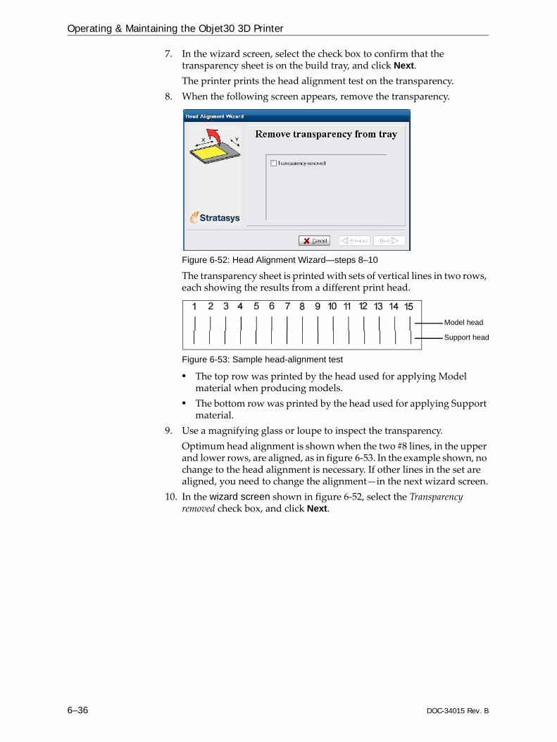
Operating & Maintaining the Objet30 3D Printer
6–36 DOC-34015 Rev. B
7. In the wizard screen, select the check box to confirm that the transparency sheet is on the build tray, and click Next.The printer prints the head alignment test on the transparency.
8. When the following screen appears, remove the transparency.
Figure 6-52: Head Alignment Wizard—steps 8–10
The transparency sheet is printed with sets of vertical lines in two rows, each showing the results from a different print head.
Figure 6-53: Sample head-alignment test
• The top row was printed by the head used for applying Model material when producing models.
• The bottom row was printed by the head used for applying Support material.
9. Use a magnifying glass or loupe to inspect the transparency.Optimum head alignment is shown when the two #8 lines, in the upper and lower rows, are aligned, as in figure 6‐53. In the example shown, no change to the head alignment is necessary. If other lines in the set are aligned, you need to change the alignment—in the next wizard screen.
10. In the wizard screen shown in figure 6‐52, select the Transparency removed check box, and click Next.
Model head
Support head

DOC-34015 Rev. B 6–37
Objet30 User Guide
The first in a series of alignment screens appears.
Figure 6-54: Head alignment screen
11. In the head‐alignment screen, select the number that indicates which lines align in the upper and lower rows.Note: Because the alignment of the middle lines is optimum, the number “8” is selected, by default, in the wizard screen. This does not change the head alignment. If you select other numbers, the wizard adjusts the head alignment, accordingly.
12. Click Next.The following screen is displayed.
Figure 6-55: Update confirmation screen
13. Continue as follows:• To make the alignment changes in the printer, make sure that Yes is
selected, and click Next.• To recheck the alignment test results before making the alignment
changes in the printer, click Previous.• If you do not want to make alignment changes in the printer at this
time, select No and click Next.

Operating & Maintaining the Objet30 3D Printer
6–38 DOC-34015 Rev. B
14. In the following screen, you can choose to either repeat the head alignment procedure or close the wizard. • If the most closely aligned vertical lines for a print head were at
either extreme, choose Yes to run the Head Alignment Wizard again, then click Next. The transparency test will show if the heads are now properly aligned, and—if not—the wizard will allow you to “fine tune” the alignment.
• If the vertical lines for the print heads were not aligned at either extreme, choose No to close the wizard, then click Next.
Figure 6-56: Repeat head alignment option
If the Head Alignment Wizard was opened from the Head Optimization Wizard after replacing print heads, the printer application closes and re-opens when you click Done in the final wizard screen.
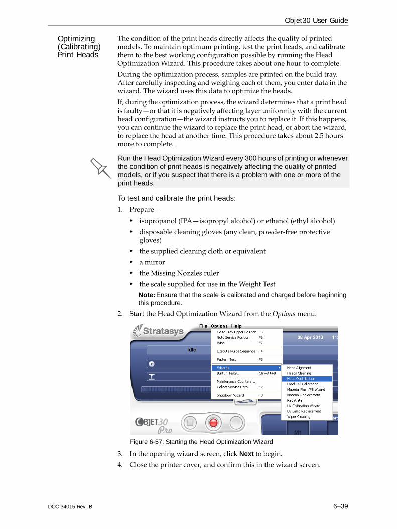
DOC-34015 Rev. B 6–39
Objet30 User Guide
Optimizing (Calibrating) Print Heads
The condition of the print heads directly affects the quality of printed models. To maintain optimum printing, test the print heads, and calibrate them to the best working configuration possible by running the Head Optimization Wizard. This procedure takes about one hour to complete.During the optimization process, samples are printed on the build tray. After carefully inspecting and weighing each of them, you enter data in the wizard. The wizard uses this data to optimize the heads. If, during the optimization process, the wizard determines that a print head is faulty—or that it is negatively affecting layer uniformity with the current head configuration—the wizard instructs you to replace it. If this happens, you can continue the wizard to replace the print head, or abort the wizard, to replace the head at another time. This procedure takes about 2.5 hours more to complete.
To test and calibrate the print heads:1. Prepare—
• isopropanol (IPA—isopropyl alcohol) or ethanol (ethyl alcohol)• disposable cleaning gloves (any clean, powder‐free protective
gloves)• the supplied cleaning cloth or equivalent• a mirror• the Missing Nozzles ruler• the scale supplied for use in the Weight Test
Note:Ensure that the scale is calibrated and charged before beginning this procedure.
2. Start the Head Optimization Wizard from the Options menu.
Figure 6-57: Starting the Head Optimization Wizard
3. In the opening wizard screen, click Next to begin.4. Close the printer cover, and confirm this in the wizard screen.
Run the Head Optimization Wizard every 300 hours of printing or whenever the condition of print heads is negatively affecting the quality of printed models, or if you suspect that there is a problem with one or more of the print heads.
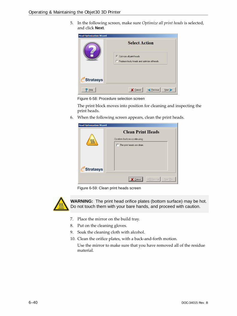
Operating & Maintaining the Objet30 3D Printer
6–40 DOC-34015 Rev. B
5. In the following screen, make sure Optimize all print heads is selected, and click Next.
Figure 6-58: Procedure selection screen
The print block moves into position for cleaning and inspecting the print heads.
6. When the following screen appears, clean the print heads.
Figure 6-59: Clean print heads screen
7. Place the mirror on the build tray.8. Put on the cleaning gloves.9. Soak the cleaning cloth with alcohol.10. Clean the orifice plates, with a back‐and‐forth motion.
Use the mirror to make sure that you have removed all of the residue material.
WARNING: The print head orifice plates (bottom surface) may be hot. Do not touch them with your bare hands, and proceed with caution.
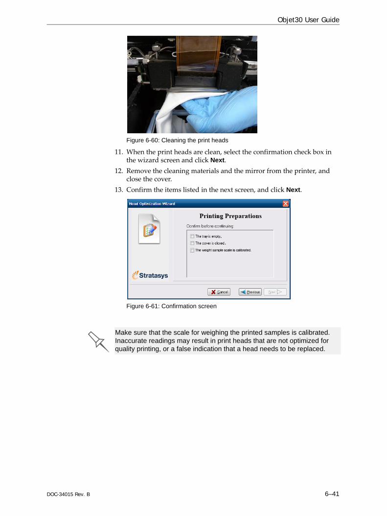
DOC-34015 Rev. B 6–41
Objet30 User Guide
Figure 6-60: Cleaning the print heads
11. When the print heads are clean, select the confirmation check box in the wizard screen and click Next.
12. Remove the cleaning materials and the mirror from the printer, and close the cover.
13. Confirm the items listed in the next screen, and click Next.
Figure 6-61: Confirmation screen
Make sure that the scale for weighing the printed samples is calibrated. Inaccurate readings may result in print heads that are not optimized for quality printing, or a false indication that a head needs to be replaced.

Operating & Maintaining the Objet30 3D Printer
6–42 DOC-34015 Rev. B
14. Select the confirmation check box in the wizard screen and click Next.
Figure 6-62: Printing Weight Test
The printer prepares itself for printing (by running the reinitaite process). Then, 6 or 12 samples are printed on the build tray, depending on the printer model. This can take up to 80 minutes.
15. When the following screen appears, open the printer cover to inspect the printed samples.
Figure 6-63: Data-entry screen for some Objet30 printers
Figure 6-64: Data-entry screen for Objet30 Pro printers
The layout of the data entry screen matches the printed samples on the build tray. You enter the data for the sample indicated by in the screen.

DOC-34015 Rev. B 6–43
Objet30 User Guide
16. Using the Missing Nozzles ruler, determine the number of clogged (“missing”) nozzles.
Figure 6-65: Missing Nozzles ruler
Clogged nozzles are seen in Weight Test samples as missing rows of printed material. a. Place the alignment line on the right side of the ruler next to the
bottom of the sample, as shown.
Figure 6-66: Aligning the ruler to the bottom of the sample
b. Check if there is a space below the line on the ruler marked “Maximum height of sample.” A space below this line indicates missing nozzles at the extremes of the printed sample. The numbers indicate how many printed rows (nozzles) are missing. Remember this number.
Figure 6-67: Measuring missing nozzles at the extremes of the sample
Note:Because you align the ruler to the bottom of the printed sample, missing nozzles at the bottom edge are measured at the top of the ruler.
Printed sample
Line on ruler

Operating & Maintaining the Objet30 3D Printer
6–44 DOC-34015 Rev. B
c. Check if there are gaps in the printed sample by matching the gap in the sample with a line on the Missing Nozzles ruler. The number on the ruler next to the line indicates the number of missing rows/nozzles.
Figure 6-68: Measuring a missing row in a printed sample
In the example above, the number of missing nozzles is two (2).d. Enter the total number of missing rows in the wizard screen (in the
“missing nozzles” field). Note:During this procedure, the roller does not smooth the surface of the printed samples. Do not mistake the visible lines in the sample for missing material.
Figure 6-69: Printed sample for Head Optimization
17. Carefully remove the sample, weigh it, and enter the weight in the wizard screen.Be sure to remove and weigh the entire sample, even if it breaks into several pieces.
18. After entering the number of missing nozzles and the weight of the sample, click Apply or press Enter.The data‐entry‐indicator moves to the next position.
19. Enter the data for all printed samples.
Missing row
Printed sample
Ruler
To change an entry, click Edit Data, enter the correct data, and click Save.

DOC-34015 Rev. B 6–45
Objet30 User Guide
20. When you have entered the data for all printed samples, click Next. The wizard uses the data collected to analyze the condition of the print heads, and optimizes them so they print models with a uniform layer of material. • If the heads are in satisfactory condition, the following wizard
screen appears.1
Figure 6-70: Final wizard screen, after optimizing print heads
Note:To apply the optimized settings to the print heads, the printer application must be restarted. When you click Done, the application closes and re-opens.
• If the wizard determines that a print head is faulty—or that it is negatively affecting model quality with the current head configuration—the wizard instructs you to replace it. In this case, the following screen appears.
Figure 6-71: Defective print heads found
1. However, after optimizing print heads following their replacement, a screen appears enabling you to continue by running the Head Alignment Wizard (see page 35). This is necessary before printing models. If you choose not to align the heads at this time, the printer application closes and re‐opens when you click Done.

Operating & Maintaining the Objet30 3D Printer
6–46 DOC-34015 Rev. B
To replace print heads, you need these tools and materials:• replacement print head(s)• isopropanol (IPA—isopropyl alcohol) or ethanol (ethyl alcohol)• disposable cleaning gloves (supplied with the print head; or use
any clean, powder‐free protective gloves)• a supplied cleaning cloth or equivalent• the scale supplied for use in the Head Optimization Wizard
(Weight Test)• the Missing Nozzles ruler
21. Choose Replace faulty head(s) if you are prepared to replace the print heads now. or—Choose Abort wizard if you want to replace the print heads at another time.
If you are replacing the print heads now, the wizard guides you through the procedure when you click Next. Continue with “Preparing the Print Block” on page 48.
Replacing Print Heads
The condition of the print heads directly affects the quality of printed models. You may need to replace a print head if one or more of the following symptoms occurs:• The Head Optimization Wizard determines that a print head is
defective. (See “Optimizing (Calibrating) Print Heads” on page 39.)• There are noticeable grooves in the surface of printed models.• Visual inspection of the head reveals that its surface is damaged—
peeling or bubbles in the nozzle area.• The printer interface displays a warning or malfunction message
relating to a print head—Head Heater temperature timeoutHead Heater thermistor openHead Heater thermistor short
Replace print heads only after consulting with a Stratasys-authorized customer-support engineer.
Replace print heads only after consulting with an authorized customer-support engineer.

DOC-34015 Rev. B 6–47
Objet30 User Guide
The Head Optimization Wizard guides you through the procedure of replacing a print head, and adjusts printer components to enable you to perform it. Only replace a print head with the aid of the wizard. The entire procedure takes about 2.5 hours, and consists of the following phases: A. Identifying the head(s) needing replacement.
This is normally done by the Head Optimization Wizard. Otherwise, evidence of physical damage to the head surface or a malfunction message indicates which head needs replacing.
B. Preparing the print block for head replacement.This is done automatically when you run the Wizard.
C. Removing the defective print head. D. Installing a new print head.E. Optimizing the print heads (done automatically by the wizard).F. Performing head alignment.
To replace a print head:1. Prepare—
• replacement print head(s)• isopropanol (IPA—isopropyl alcohol) or ethanol (ethyl alcohol)• disposable cleaning gloves (supplied with the print head; or use
any clean, powder‐free protective gloves)• a supplied cleaning cloth or equivalent• the scale supplied for use in the Head Optimization Wizard
(Weight Test)• the Missing Nozzles RulerNote: Make sure that you have these items and that the scale is calibrated and charged before performing the head-replacement procedure.
2. Start the Head Optimization Wizard from the Options menu (see figure 6‐38 on page 29).
3. In the opening wizard screen, click Next to begin.4. In the following screen, select Replace faulty heads, and click Next.
Figure 6-72: Procedure selection screen

Operating & Maintaining the Objet30 3D Printer
6–48 DOC-34015 Rev. B
Preparing thePrint Block
5. Select the print head(s) needing replacement, and click Next.
Figure 6-73: Head selection screen
The printer heats and empties the print block, and prepares the printer.
Figure 6-74: Printer preparation progress screen
6. The following screen appears when the printer is ready for you to replace print heads.
Figure 6-75: Printer ready for head replacement

DOC-34015 Rev. B 6–49
Objet30 User Guide
7. Put on the protective gloves and open the printer cover.Note: The printer disconnects power to the heads for your safety.
Figure 6-76: Print-head replacement confirmation
Removing theDefective Head
Removing the Support Print Head
To replace the Model print head, you must first remove the Support print head.

Operating & Maintaining the Objet30 3D Printer
6–50 DOC-34015 Rev. B
If you do not need to replace the Model print head, continue with “Installing the Support Print Head” on page 6‐52.
Removing the Model Print Head
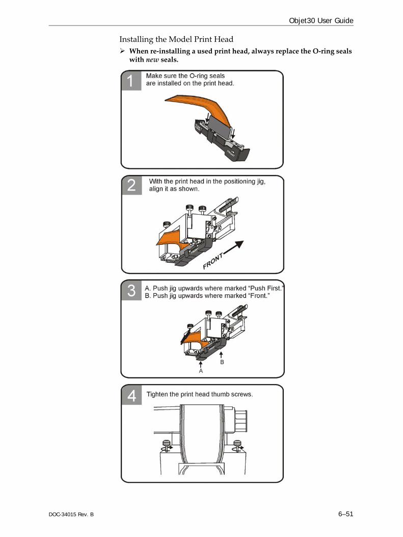
DOC-34015 Rev. B 6–51
Objet30 User Guide
Installing the Model Print HeadWhen re‐installing a used print head, always replace the O‐ring seals with new seals.

Operating & Maintaining the Objet30 3D Printer
6–52 DOC-34015 Rev. B
Installing the Support Print HeadWhen re‐installing a used print head, always replace the O‐ring seals with new seals.
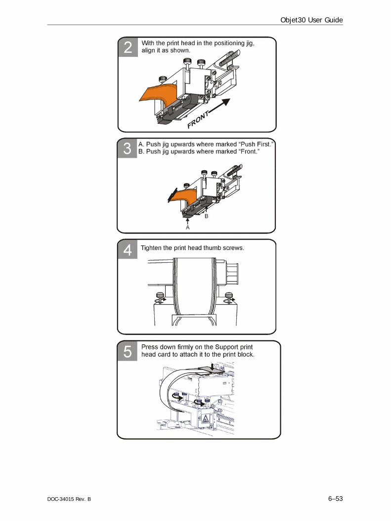
DOC-34015 Rev. B 6–53
Objet30 User Guide

Operating & Maintaining the Objet30 3D Printer
6–54 DOC-34015 Rev. B
8. In the Replace print heads screen (see figure 6‐76 on page 49), select the check box to confirm that you have replaced the head(s), and click Next.
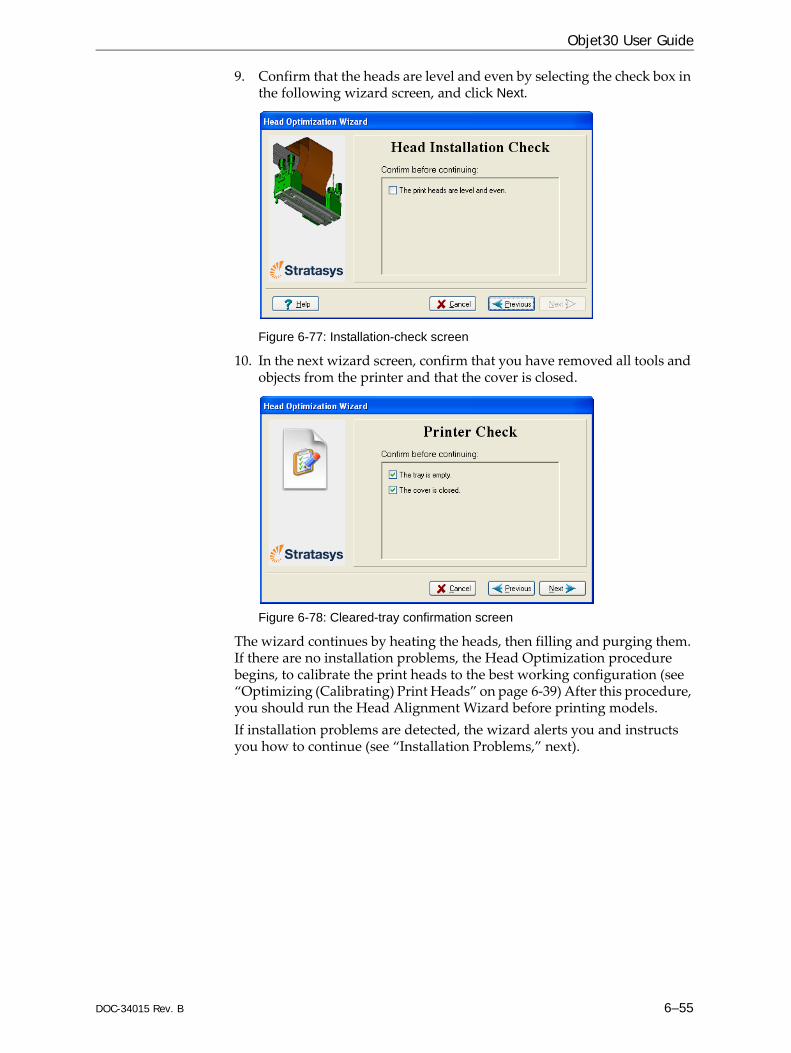
DOC-34015 Rev. B 6–55
Objet30 User Guide
9. Confirm that the heads are level and even by selecting the check box in the following wizard screen, and click Next.
Figure 6-77: Installation-check screen
10. In the next wizard screen, confirm that you have removed all tools and objects from the printer and that the cover is closed.
Figure 6-78: Cleared-tray confirmation screen
The wizard continues by heating the heads, then filling and purging them. If there are no installation problems, the Head Optimization procedure begins, to calibrate the print heads to the best working configuration (see “Optimizing (Calibrating) Print Heads” on page 6‐39) After this procedure, you should run the Head Alignment Wizard before printing models.If installation problems are detected, the wizard alerts you and instructs you how to continue (see “Installation Problems,” next).
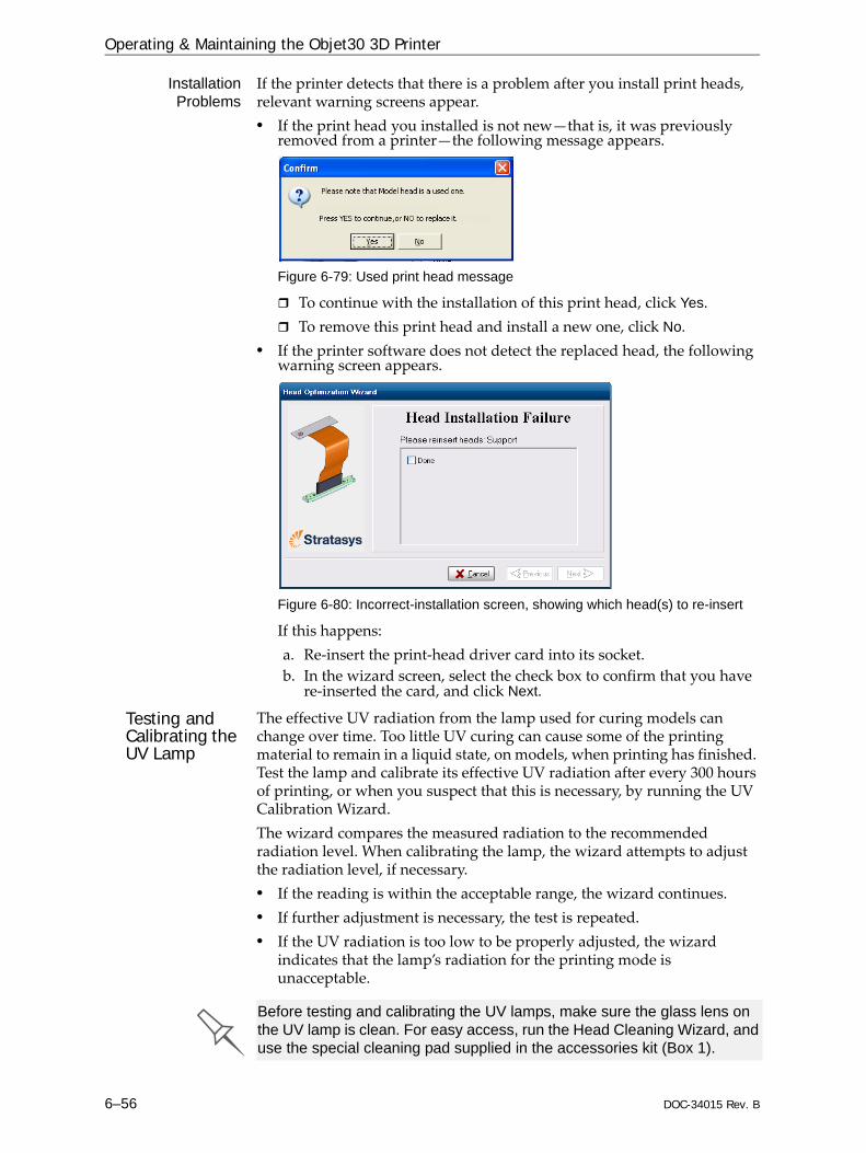
Operating & Maintaining the Objet30 3D Printer
6–56 DOC-34015 Rev. B
InstallationProblems
If the printer detects that there is a problem after you install print heads, relevant warning screens appear.• If the print head you installed is not new—that is, it was previously
removed from a printer—the following message appears.
Figure 6-79: Used print head message
To continue with the installation of this print head, click Yes.To remove this print head and install a new one, click No.
• If the printer software does not detect the replaced head, the following warning screen appears.
Figure 6-80: Incorrect-installation screen, showing which head(s) to re-insert
If this happens: a. Re‐insert the print‐head driver card into its socket.b. In the wizard screen, select the check box to confirm that you have
re‐inserted the card, and click Next.
Testing and Calibrating the UV Lamp
The effective UV radiation from the lamp used for curing models can change over time. Too little UV curing can cause some of the printing material to remain in a liquid state, on models, when printing has finished. Test the lamp and calibrate its effective UV radiation after every 300 hours of printing, or when you suspect that this is necessary, by running the UV Calibration Wizard.The wizard compares the measured radiation to the recommended radiation level. When calibrating the lamp, the wizard attempts to adjust the radiation level, if necessary.• If the reading is within the acceptable range, the wizard continues. • If further adjustment is necessary, the test is repeated. • If the UV radiation is too low to be properly adjusted, the wizard
indicates that the lamp’s radiation for the printing mode is unacceptable.
Before testing and calibrating the UV lamps, make sure the glass lens on the UV lamp is clean. For easy access, run the Head Cleaning Wizard, and use the special cleaning pad supplied in the accessories kit (Box 1).

DOC-34015 Rev. B 6–57
Objet30 User Guide
To test and calibrate UV lamp radiation:1. Start the UV Calibration Wizard from the Options menu (see figure 6‐38
on page 6‐29).2. In the following screen, select UV Intensity Calibration to adjust the
lamp’s radiation level to the acceptable range.
Figure 6-81: UV Test/Calibration selection
3. Make sure that the build tray is clear (empty). Confirm this in the wizard screen and click Next.
Figure 6-82: Printer preparation
4. Expose the UV sensor by sliding its cover to the right, and check that the glass is clean.
Figure 6-83: UV sensor exposed
5. If necessary, clean the glass over the UV sensor with a cleaning cloth and alcohol (IPA).Do not use the abrasive cleaning pad to clean the glass.

Operating & Maintaining the Objet30 3D Printer
6–58 DOC-34015 Rev. B
When you click Next, the UV lamp powers up and stabilizes. (This takes several minutes.) Then, the print block passes over the sensor and the wizard compares the measured radiation to the recommended level.
Figure 6-84: UV measurement progress
If the UV level measured is not acceptable, the wizard calibrates the UV lamp by adjusting the current supplied to it, and then tests it again.When completed, the wizard displays the condition of the lamp, after calibration.
Figure 6-85: Final condition of UV lamp—acceptable intensity level
Figure 6-86: Final condition of UV lamp—unacceptable intensity level
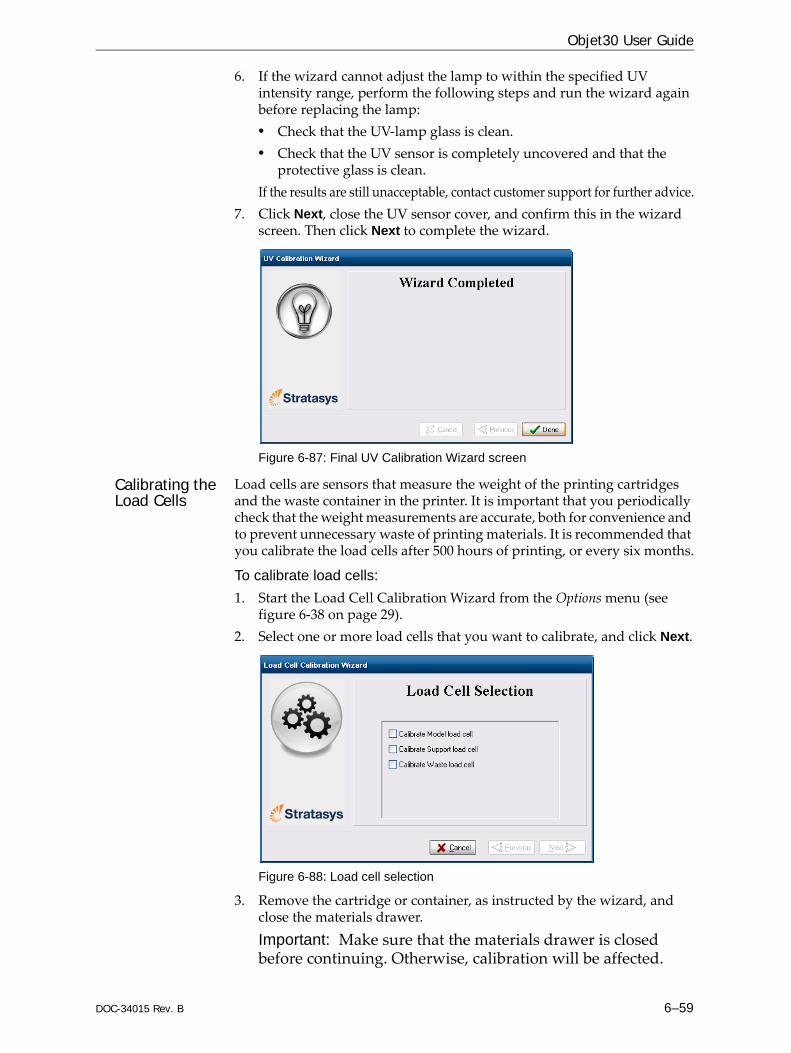
DOC-34015 Rev. B 6–59
Objet30 User Guide
6. If the wizard cannot adjust the lamp to within the specified UV intensity range, perform the following steps and run the wizard again before replacing the lamp:• Check that the UV‐lamp glass is clean.• Check that the UV sensor is completely uncovered and that the
protective glass is clean.If the results are still unacceptable, contact customer support for further advice.
7. Click Next, close the UV sensor cover, and confirm this in the wizard screen. Then click Next to complete the wizard.
Figure 6-87: Final UV Calibration Wizard screen
Calibrating the Load Cells
Load cells are sensors that measure the weight of the printing cartridges and the waste container in the printer. It is important that you periodically check that the weight measurements are accurate, both for convenience and to prevent unnecessary waste of printing materials. It is recommended that you calibrate the load cells after 500 hours of printing, or every six months.
To calibrate load cells:1. Start the Load Cell Calibration Wizard from the Options menu (see
figure 6‐38 on page 29). 2. Select one or more load cells that you want to calibrate, and click Next.
Figure 6-88: Load cell selection
3. Remove the cartridge or container, as instructed by the wizard, and close the materials drawer. Important: Make sure that the materials drawer is closed before continuing. Otherwise, calibration will be affected.

Operating & Maintaining the Objet30 3D Printer
6–60 DOC-34015 Rev. B
4. Select the confirmation check box and click Next.
Figure 6-89: Confirmation of cartridge removal
5. In the next wizard screen, observe the numbers and wait until the level is relatively stable—two units above or below the average level shown.
Figure 6-90: Level stabilization
6. Select the check box, and click Next.If you need to calibrate more than one load cell, the next calibration screen appears. Repeat steps 5 and 6 until all of the load cells are calibrated.
7. Click Done in the final wizard screen.
Figure 6-91: Final wizard screen

DOC-34015 Rev. B 6–61
Objet30 User Guide
8. Replace the cartridges/container.
Replacing the Odor Filter
If the printer exhaust is not connected to an external ventilation system, a built‐in activated‐carbon filter removes odors from printing materials. This filter should be replaced regularly (as necessary) to keep your working environment pleasant. This is normally done during the preventive‐maintenance service visit.
To replace the odor filter:1. Locate the filter drawer at the rear of the printer and pull it open.
Figure 6-92: Rear of the Objet30 printer
2. Remove the used filter. (You can push it out from underneath the drawer.)
Figure 6-93: Odor filter in drawer
3. Insert a new filter and close the drawer.
When replacing the waste container, hold the waste bag with one hand while connecting the waste tube. Otherwise, the bag will be twisted, and the flow of waste will be restricted.Make sure to replace the metal cover over the waste container. Operating the printer without the cover results in an inaccurate measurement of the waste weight, which will cause waste to overflow into the printer.
Odor filter drawer
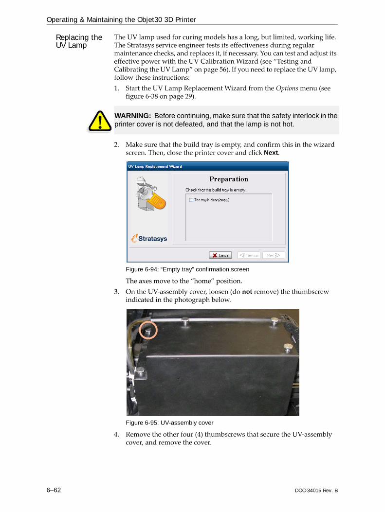
Operating & Maintaining the Objet30 3D Printer
6–62 DOC-34015 Rev. B
Replacing the UV Lamp
The UV lamp used for curing models has a long, but limited, working life. The Stratasys service engineer tests its effectiveness during regular maintenance checks, and replaces it, if necessary. You can test and adjust its effective power with the UV Calibration Wizard (see “Testing and Calibrating the UV Lamp” on page 56). If you need to replace the UV lamp, follow these instructions: 1. Start the UV Lamp Replacement Wizard from the Options menu (see
figure 6‐38 on page 29).
2. Make sure that the build tray is empty, and confirm this in the wizard screen. Then, close the printer cover and click Next.
Figure 6-94: “Empty tray” confirmation screen
The axes move to the “home” position.3. On the UV‐assembly cover, loosen (do not remove) the thumbscrew
indicated in the photograph below.
Figure 6-95: UV-assembly cover
4. Remove the other four (4) thumbscrews that secure the UV‐assembly cover, and remove the cover.
WARNING: Before continuing, make sure that the safety interlock in the printer cover is not defeated, and that the lamp is not hot.

DOC-34015 Rev. B 6–63
Objet30 User Guide
5. Disconnect the UV lamp cable and the fan cable.
Figure 6-96: Disconnecting the UV lamp assembly (top view)
6. Loosen the two side screws securing the UV lamp assembly to the printer.
Figure 6-97: UV-lamp-assembly
7. Remove the assembly, and place it on a flat surface.
UV-lamp connector
UV-fan connector
Securing screws

Operating & Maintaining the Objet30 3D Printer
6–64 DOC-34015 Rev. B
8. Loosen the screws securing the UV lamp cover and remove the cover.
Figure 6-98: UV-lamp-cover screws
9. Loosen the two screws securing the UV reflector.
Figure 6-99: UV-reflector screws
10. Remove the UV reflector by raising it slightly, then pulling it out of the housing at an angle, from the bottom.
Figure 6-100: Removing the UV reflector from the UV assembly
Cover screws
Reflector screws

DOC-34015 Rev. B 6–65
Objet30 User Guide
11. Discard the old reflector and lamp.
12. Insert the new UV lamp/reflector unit into the housing.13. Make sure that the UV‐lamp cable is in place, inside the housing, and
then tighten the securing screws.
Figure 6-101: Cable position when installing the UV lamp
14. Replace the lamp cover, and tighten the securing screws.15. Replace the UV lamp assembly in the printer, making sure that the
cable fits into the slot together with the side securing screw.
Figure 6-102: UV-lamp cable after replacing the assembly
16. Tighten the two side securing screws.17. In the wizard screen, confirm that you have replaced the lamp and that
the black strip is attached, then click Next.
Figure 6-103: UV-installation confirmation screen
Dispose of the used UV lamp in accordance with environmental and safety requirements.

Operating & Maintaining the Objet30 3D Printer
6–66 DOC-34015 Rev. B
The wizard operates the lamp to test if it is installed correctly. If the lamp does not light, the wizard prompts you to check the power connections and to re‐install the lamp.
Figure 6-104: Final wizard screen
Note: The UV lamp remains on until you click Done.
Built-in Tests A sanity check of the software parameters is available from the Built‐in Tests interface. Because this effects the operation of the printer, you can only open the Built‐in Tests interface when the system is not printing.
AccessingBuilt-in Tests
To open the Built-in Tests screen, do one of the following: • From the Options menu, select Built-In Tests.• Press Ctrl+Alt+B.
Figure 6-105: Selecting Built-In Tests from the Options menu
After replacing the UV lamp: • Calibrate its power by running the UV Calibration Wizard (see “Testing
and Calibrating the UV Lamp” on page 6-56). Wait at least two minutes for the UV lamp to cool before starting the UV Calibration Wizard.
• Calibrate the new UV lamp again after 100 hours of printing.

DOC-34015 Rev. B 6–67
Objet30 User Guide
Test Interface The Built In Tests screen lists pre‐configured tests.
Figure 6-106:Built In Tests screen
StatusThe “S” column shows the results of the test after you run it:
To run the test:Select the check box and click .
After you run the test, the Save and View command buttons are added to the Built In Tests screen.
Figure 6-107: BIT command buttons
Test Results To save and view a report of all of the tests:Use the Save and View command buttons.
Test successfully completed.
Test failed.
Unknown results. (The test has not been run yet.)

Operating & Maintaining the Objet30 3D Printer
6–68 DOC-34015 Rev. B
Replacing the Waste Container
Printer waste contains partially cured polymeric material, collected during normal operation and maintenance of the printer. For safety and environmental reasons, this material is kept in a special leak‐proof, disposable container.The container has a capacity of 1.8 kilograms of waste material—usually enough for several weeks of printer use. The printer software displays a warning message when there is 1.5 kilograms of material in the container, and stops the printing when the net weight reaches 1.8 kilograms. Above 1.5 kilograms, the software does not allow you to start a print job (or a printing activity) until you replace the waste container. You can monitor the weight of the waste container in the Maintenance screen of the printer interface.
To monitor the waste weight (and other indicators) in the printer:In the main printer interface screen, click the display toggle to view the printer indicators.
Figure 6-108: Printer interface, showing waste weight (red background indicates operator alert)
The waste container consists of a sealed bag inside a cardboard box. You typically dispose of the entire waste container—including the box. Therefore, you must assemble a new box and insert a new waste bag before you can install it in the printer.
To prepare a new waste container:1. Assemble the cardboard box, making sure to punch out the perforated
sections.2. Fold a new waste bag—so it fits in the box—and insert the bag’s screw‐
connector into the hole in the top of the box.Note: Do not close the box until you connect the waste drain tube from the printer.
Display toggle button
Waste weight
Replacement boxes, waste bags, and sealing caps are supplied in the Objet printer start-up kit and in the preventive-maintenance kit.

DOC-34015 Rev. B 6–69
Objet30 User Guide
To replace the waste container:1. Open the materials drawer.2. Remove the fireproof cover from the waste container.
Figure 6-109: Removing the waste-container cover
3. Unscrew the cap connecting the waste drain tube to the container.4. Carefully lift out the waste container to remove it from the printer.5. Close the full container with the cap supplied with the new waste
container.6. Place the new waste container in the materials drawer, and attach the
cap connected to the drain tube. Important: Hold the waste bag with one hand while attaching the waste tube. Otherwise, the bag will be twisted, and the flow of waste will be restricted.
7. Close the new waste‐container box.
Figure 6-110: Waste container with drain tube attached

Operating & Maintaining the Objet30 3D Printer
6–70 DOC-34015 Rev. B
8. Place the fireproof cover over the waste container, making sure that the drain tube is free and not bent.
Figure 6-111: Fireproof cover installed over the waste container
Note: Operating the printer without the waste-container cover results in an inaccurate measurement of the waste weight, which will cause waste to overflow into the printer.
9. Close the materials drawer.
Cleaning the Exterior Panels
The painted exterior plastic panels of Objet 3D printers have a durable finish, offering excellent chemical resistance to common cleaning materials. However, it is recommended that you use only a mild soap solution for routine cleaning.
Backing-Up and Restoring Printer Settings
Printer modes and configuration settings are stored in files on the printer computer. You can back up these files, and restore them, if necessary, using desktop icons.
Figure 6-112: Backup and restore desktop icons
ReInitiate Wizard
One of the wizards listed in the Options menu is ReInitiate. You normally do not have to run this wizard. The process that this wizard controls runs automatically, when needed, as part of the Pre‐print mode (before printing begins). Run this wizard only if a Stratasys Customer Support engineer instructs you to do so.
Dispose of the full waste container in accordance with environmental and safety requirements.

DOC-34015 Rev. B 7–1
Handling Printed Models
Removing Models After Printing.............................................................. 2Removing the Support Material................................................................ 2Post‐Printing Treatment for Models Printed with Objet VeroClear..... 4Storing Models............................................................................................. 5
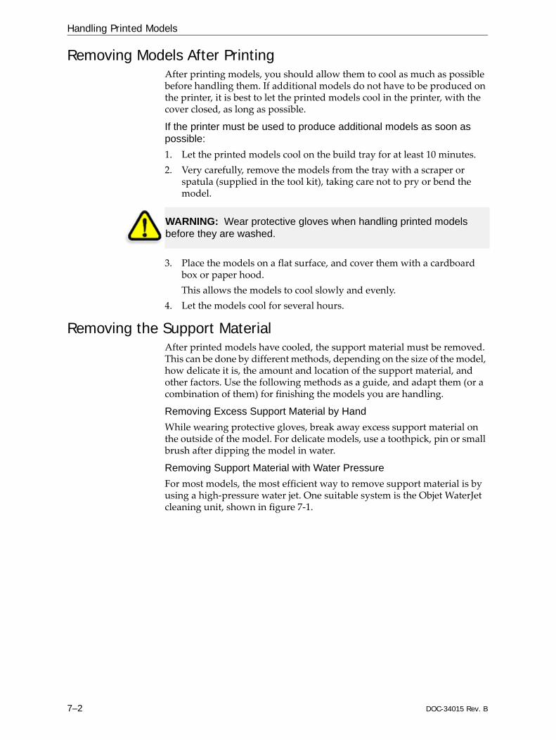
Handling Printed Models
7–2 DOC-34015 Rev. B
Removing Models After PrintingAfter printing models, you should allow them to cool as much as possible before handling them. If additional models do not have to be produced on the printer, it is best to let the printed models cool in the printer, with the cover closed, as long as possible.
If the printer must be used to produce additional models as soon as possible:1. Let the printed models cool on the build tray for at least 10 minutes. 2. Very carefully, remove the models from the tray with a scraper or
spatula (supplied in the tool kit), taking care not to pry or bend the model.
3. Place the models on a flat surface, and cover them with a cardboard box or paper hood.This allows the models to cool slowly and evenly.
4. Let the models cool for several hours.
Removing the Support MaterialAfter printed models have cooled, the support material must be removed. This can be done by different methods, depending on the size of the model, how delicate it is, the amount and location of the support material, and other factors. Use the following methods as a guide, and adapt them (or a combination of them) for finishing the models you are handling.
Removing Excess Support Material by HandWhile wearing protective gloves, break away excess support material on the outside of the model. For delicate models, use a toothpick, pin or small brush after dipping the model in water.
Removing Support Material with Water PressureFor most models, the most efficient way to remove support material is by using a high‐pressure water jet. One suitable system is the Objet WaterJet cleaning unit, shown in figure 7‐1.
WARNING: Wear protective gloves when handling printed models before they are washed.

DOC-34015 Rev. B 7–3
Objet30 User Guide
Figure 7-1: Objet WaterJet Cleaning Unit
To clean a model using this device, you place it in the chamber, and you manipulate it and the jet using the built‐in, waterproof sleeves. A pump turns ordinary tap water into a high‐pressure jet, and a wiper keeps the window clear.
Removing Support Material with Caustic SodaSoak models in a 2‐percent solution of caustic soda (sodium hydroxide) to remove support material from difficult‐to‐reach areas and to give the model a smooth, clean finish. The amount of time you soak the model in the solution depends on how delicate it is and how much support material needs to be removed, but it is typically between half‐an‐hour and several hours. In any case, you should remove as much support material as possible before the caustic soda treatment, and rinse the model thoroughly (with a water jet) afterwards.
Use caution when cleaning delicate models with high-pressure water systems.
WARNING: Caustic soda may cause chemical burns, scarring and blindness. Mixing it with water generates heat that could ignite other materials. Never pour water into a caustic soda solution. When diluting the solution, always add caustic soda to water. Take adequate safety precautions; always use nitrile gloves when handling caustic soda and models soaked in it.

Handling Printed Models
7–4 DOC-34015 Rev. B
Post-Printing Treatment for Models Printed with Objet VeroClearModels made with Objet VeroClear have a slight yellow tint when removed from the printer. This is especially true for models printed with a glossy finish. The yellow tint fades naturally over time, but you can greatly accelerate this process by using a suitable photobleaching treatment.As a rule, best clarity is achieved when parts are printed with a matte finish, and treated as explained below.Photobleaching models involves exposing them to light. To achieve highly controlled and predictable results, a professional illumination chamber is recommended. However, adequate results may be obtained using ordinary desk lamps fitted with suitable fluorescent elements.
Photo-Bleaching Instructions Follow these instructions for photobleaching printed models.
• The fluorescent lamps should be rated 45W, 6500K.• When using desk lamps, place the models in a container covered with
aluminum foil. Use at least two lamps, more when treating models in a large container.
• Arrange the models with enough space between them to allow light to reach all sides of each model.
• Verify that the ambient temperature around the models is approximately 40ºC (104ºF). Higher temperatures may cause model distortion; lower temperatures may not produce satisfactory results. When using desk lamps, you can achieve the required temperature by positioning the lamps approximately 10 cm (4 in.) above the models.
• Inspect the models after six hours of treatment. For parts with a matte finish, this should be enough. Polish and lacquer the parts.For parts with a glossy finish, continue the photobleaching treatment for up to 18 hours more.
In Stratasys laboratories, there was a tint reduction of approximately 70% within six hours. After 24 hours, tint was reduced by approximately 90%.
Figure 7-2: Illumination chamber Figure 7-3: Desk lamps
More information about this treatment is available in the application note VeroClear RGD810 Model Material.

DOC-34015 Rev. B 7–5
Objet30 User Guide
Storing ModelsModels are cured as they are printed, making them safe and stable for a long time. However, proper storage conditions are necessary to prevent deforming.• Keep printed models at room temperature and in a low‐humidity
environment.• Do not expose models to direct sunlight and other heat sources.
