omron - h7ec
TRANSCRIPT
8/3/2019 OMRON - h7ec
http://slidepdf.com/reader/full/omron-h7ec 1/5
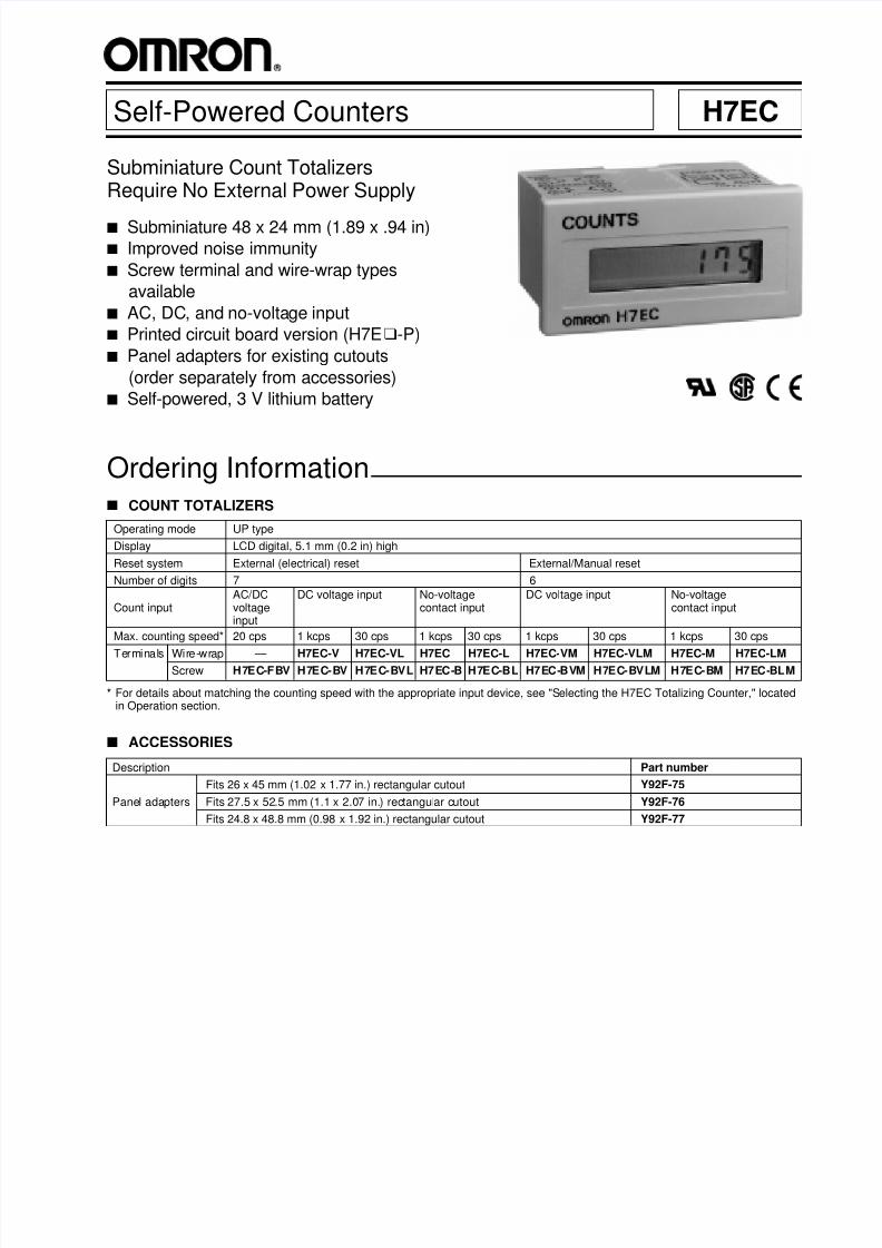
Self-Powered Counters H7EC
Subminiature Count TotalizersRequire No External Power Supply
s Subminiature 48 x 24 mm (1.89 x .94 in)
s Improved noise immunity
s Screw terminal and wire-wrap types
available
s AC, DC, and no-voltage input
s Printed circuit board version (H7Eu-P)
s Panel adapters for existing cutouts
(order separately from accessories)
s Self-powered, 3 V lithium battery
Operating mode UP type
Display LCD digital, 5.1 mm (0.2 in) high
Reset system External (electrical) reset External/Manual reset
Number of digits 7 6
AC/DC DC voltage input No-voltage DC voltage input No-voltageCount input voltage contact input contact input
input
Max. counting speed* 20 cps 1 kcps 30 cps 1 kcps 30 cps 1 kcps 30 cps 1 kcps 30 cps
Terminals Wire-wrap — H7EC-V H7EC-VL H7EC H7EC-L H7EC-VM H7EC-VLM H7EC-M H7EC-LMScrew H7EC-FBV H7EC-BV H7EC-BVL H7EC-B H7EC-BL H7EC-BVM H7EC-BVLM H7EC-BM H7EC-BLM
Ordering Information
.
s COUNT TOTALIZERS
* For details about matching the counting speed with the appropriate input device, see "Selecting the H7EC Totalizing Counter," locatedin Operation section.
Description Part number
Fits 26 x 45 mm (1.02 x 1.77 in.) rectangular cutout Y92F-75
Panel adapters Fits 27.5 x 52.5 mm (1.1 x 2.07 in.) rectangular cutout Y92F-76
Fits 24.8 x 48.8 mm (0.98 x 1.92 in.) rectangular cutout Y92F-77
s ACCESSORIES
8/3/2019 OMRON - h7ec
http://slidepdf.com/reader/full/omron-h7ec 2/5
H7ECH7EC
2
Supply voltage Not required (powered by buil t-in battery)
AC/DC voltage input:
24 to 240 VAC ± 10%, 50/60 Hz, or6 to 240 VDC ± 10% at "High" (logic) level
0 to 1.5 VAC ± 10%, 50/60 Hz, or0 to 2 VDC ± 10% at "Low" (logic) level
Input DC voltage input: 4.5 to 30 VDC at "High" (logic) level
0 to 2 VDC at "Low" (logic) level
No-voltage input:
Maximum short-circuit impedance: 10 kΩ max.Short-circuit residual voltage: 0.5 V max.Minimum open impedance: 500 kΩ min.
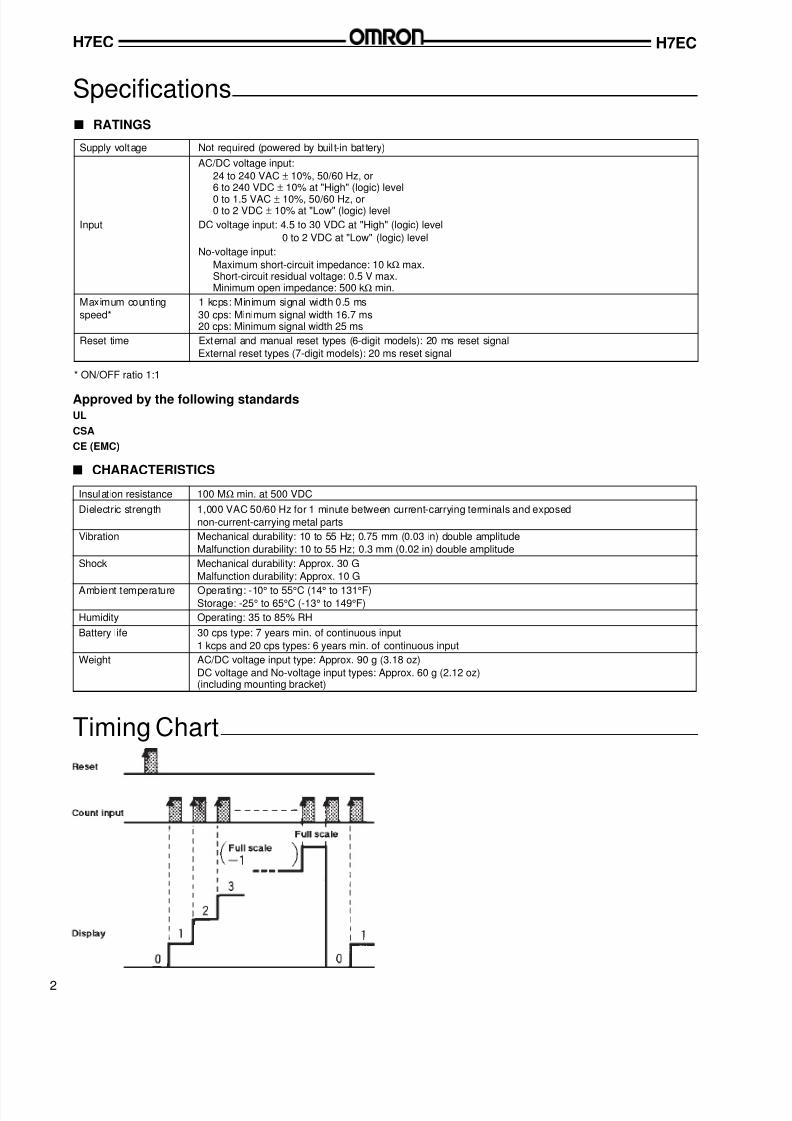
Maximum counting 1 kcps: Minimum signal width 0.5 ms
speed* 30 cps: Minimum signal width 16.7 ms20 cps: Minimum signal width 25 ms
Reset time External and manual reset types (6-digit models): 20 ms reset signal
External reset types (7-digit models): 20 ms reset signal
* ON/OFF ratio 1:1
s RATINGS
Specifications
Timing Chart
Insulat ion resistance 100 MΩ min. at 500 VDC
Dielectric strength 1,000 VAC 50/60 Hz for 1 minute between current-carrying terminals and exposed
non-current-carrying metal parts
Vibration Mechanical durability: 10 to 55 Hz; 0.75 mm (0.03 in) double amplitude
Malfunction durability: 10 to 55 Hz; 0.3 mm (0.02 in) double amplitude
Shock Mechanical durability: Approx. 30 G
Malfunction durability: Approx. 10 G
Ambient temperature Operating: -10° to 55°C (14° to 131°F)Storage: -25° to 65°C (-13° to 149°F)
Humidity Operating: 35 to 85% RH
Battery life 30 cps type: 7 years min. of continuous input
1 kcps and 20 cps types: 6 years min. of continuous input
Weight AC/DC voltage input type: Approx. 90 g (3.18 oz)
DC voltage and No-voltage input types: Approx. 60 g (2.12 oz)(including mounting bracket)
s CHARACTERISTICS
Approved by the following standardsUL
CSA
CE (EMC)
8/3/2019 OMRON - h7ec
http://slidepdf.com/reader/full/omron-h7ec 3/5
8/3/2019 OMRON - h7ec
http://slidepdf.com/reader/full/omron-h7ec 4/5
H7ECH7EC
4
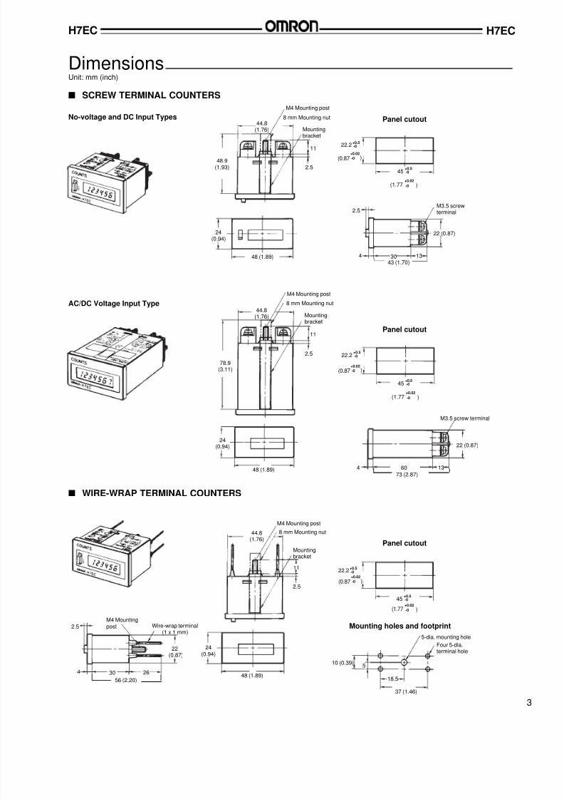
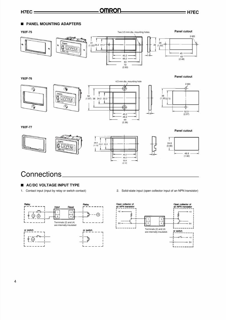
s PANEL MOUNTING ADAPTERS
Y92F-77Panel cutout
Panel cutout
Y92F-75 Two 3.5 mm dia. mounting holes
22.224.2
45.248.2
72(2.83)
63
48.2
45.2
60(2.36)
38 24.2 22.2
4.5 mm dia. mounting hole
Y92F-76
4
27.5
2-M4
4
45
4
2-M3
63(2.48)
Connections
s AC/DC VOLTAGE INPUT TYPE
1. Contact input (input by relay or switch contact) 2. Solid-state input (open collector input of an NPN transistor)
Panel cutout
Terminals (2) and (4)
are internally insulated.
Terminals (2) and (4)
are internally insulated.
31(1.22) 26
52.5(2.07)
53.8
(2.12)
28.8
(1.13)
50(1.97)
26(1.02)
38(1.50)
48.2
45.2
24.8(0.98)
48.8(1.92)
24.2 22.2
8/3/2019 OMRON - h7ec
http://slidepdf.com/reader/full/omron-h7ec 5/5
H7EC H7EC
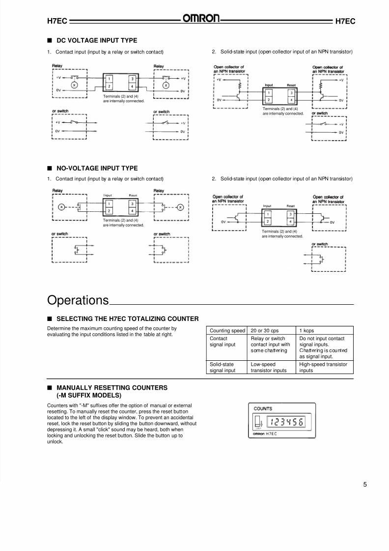
s DC VOLTAGE INPUT TYPE
s NO-VOLTAGE INPUT TYPE
1. Contact input (input by a relay or switch contact) 2. Solid-state input (open collector input of an NPN transistor)
1. Contact input (input by a relay or switch contact) 2. Solid-state input (open collector input of an NPN transistor)
Operations
s SELECTING THE H7EC TOTALIZING COUNTER
Determine the maximum counting speed of the counter byevaluating the input conditions listed in the table at right.
Counting speed 20 or 30 cps 1 kcps
Contact Relay or switch Do not input contactsignal input contact input with signal inputs.
some chattering Chattering is countedas signal input.
Solid-state Low-speed High-speed transistorsignal input transistor inputs inputs
s MANUALLY RESETTING COUNTERS(-M SUFFIX MODELS)
Counters with "-M" suffixes offer the option of manual or externalresetting. To manually reset the counter, press the reset buttonlocated to the left of the display window. To prevent an accidentalreset, lock the reset button by sliding the button downward, withoutdepressing it. A small "click" sound may be heard, both whenlocking and unlocking the reset button. Slide the button up tounlock.
Terminals (2) and (4)are internally connected.
Terminals (2) and (4)
are internally connected.
Terminals (2) and (4)
are internally connected.
Terminals (2) and (4)
are internally connected.
Input Reset