open transistor faults characterization novel method...
TRANSCRIPT
53
AMSE JOURNALS –2015-Series: Modelling A; Vol. 88; N° 1; pp 53-70
Submitted Dec. 2014; Revised May 2, 2015; Accepted Sept. 15, 2015
Open Transistor Faults Characterization Novel Method for Cascaded
H-Bridge Five-Level Three-Phase Shunt Active Power Filter
L. Benyettou1, T. Benslimane1, K. Bentata1, O. Abdelkhalek2
1Laboratory of Electrical Engineering, University of M’sila,
BP-111, Riad M’Sila, 28000, Algeria,
2Department of Electrical Engineering, University of Béchar, Algeria
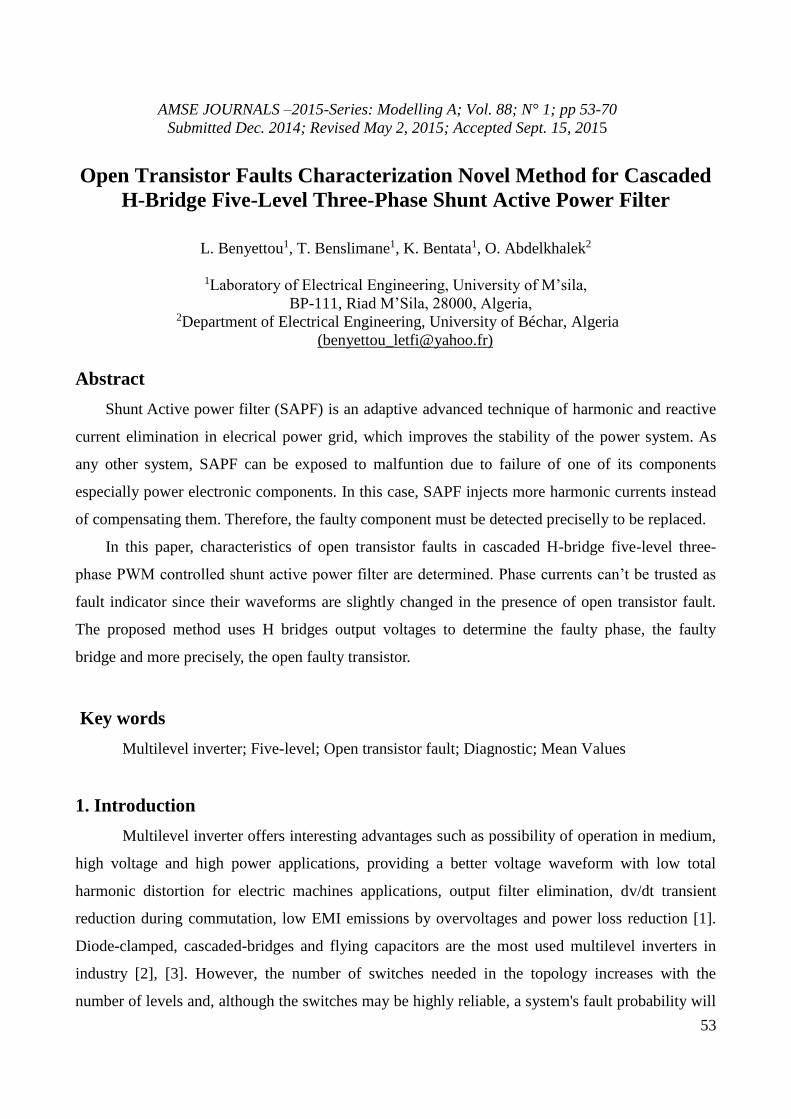
Abstract
Shunt Active power filter (SAPF) is an adaptive advanced technique of harmonic and reactive
current elimination in elecrical power grid, which improves the stability of the power system. As
any other system, SAPF can be exposed to malfuntion due to failure of one of its components
especially power electronic components. In this case, SAPF injects more harmonic currents instead
of compensating them. Therefore, the faulty component must be detected preciselly to be replaced.
In this paper, characteristics of open transistor faults in cascaded H-bridge five-level three-
phase PWM controlled shunt active power filter are determined. Phase currents can’t be trusted as
fault indicator since their waveforms are slightly changed in the presence of open transistor fault.
The proposed method uses H bridges output voltages to determine the faulty phase, the faulty
bridge and more precisely, the open faulty transistor.
Key words
Multilevel inverter; Five-level; Open transistor fault; Diagnostic; Mean Values
1. Introduction
Multilevel inverter offers interesting advantages such as possibility of operation in medium,
high voltage and high power applications, providing a better voltage waveform with low total
harmonic distortion for electric machines applications, output filter elimination, dv/dt transient
reduction during commutation, low EMI emissions by overvoltages and power loss reduction [1].
Diode-clamped, cascaded-bridges and flying capacitors are the most used multilevel inverters in
industry [2], [3]. However, the number of switches needed in the topology increases with the
number of levels and, although the switches may be highly reliable, a system's fault probability will
54
become increased [4], [5]). An unbalanced voltage is generated when a fault occurs which can
produce permanent damage to the load or complete system failure [6], [7].
Studies about fault detection in multilevel inverter and even fault-tolerant multilevel inverter
have been focused on power systems' fault analysis ([8], [9] and [10]) as first step to conceive
different techniques for obtaining a three-phase balanced output voltage ([4], [5], [11] and [12]).
Xiaomin analyzed a flying capacitor-based four-level inverter using the material redundancy
technique (using extra components) [13]. A cascaded H-bridge multilevel inverter with an
additional leg and redundancy technique regarding change of pulse width modulation (PWM) when
a fault occurs has also been described [7]. Others ([4], [5] and [6]) have shown tolerant control for
an asymmetric cascade multilevel inverter using material redundancy. Other works have analyzed a
three-level diode clamped multilevel inverter and also used extra components to tolerate faults [14].
Some of these studies used protection functions [15], e.g. passive protection could become activated
according to fault time duration [16]. Several papers ([17] and [18]) have presented a cascade
multilevel inverter and fault-tolerant technique used to change PWM modulation in semiconductor
power devices. Others works ([19]) have dealt with a fault-tolerant system for electrical machines,
such as induction motor [20], besides focusing on Aerospatiale applications and electric vehicle
applications [21]. Others considered the most common faults in static converters (short and open
circuit transistors) [22]. In the same direction, D. Kastha and B. K. Bose considered various fault
modes of a two level voltage source PWM inverter system for induction motor drive [23]. They
have studied rectifier diode short circuit, inverter transistor base driver open and inverter transistor
short-circuit conditions. However, they do not propose to reconfigure the inverter topology.
De Araujo Ribeiro R. L. et al. investigated fault detection of open-switch damage in two
level voltage source PWM motor drive systems [24]. They mainly focused on detection and
identification of the power switch in which the fault has occurred. In another paper, they
investigated the utilization of a two-leg based topology when one of the inverter legs is lost. Then
the machine operates with only two stator windings [25]. They proposed to modify PWM control to
allow continuous free operation of the drive. E. R. C. Da Silva et al. have studied fault tolerant
active power filter system [26]. They proposed to reconfigure power converter and PWM control
and examined a fault identification algorithm. T. Benslimane used active filter output currents mean
values polarities to detect and localize open switch faults in shunt active three-phase filter based on
two level voltage source inverter controlled by current Hysteresis controllers [27]. Surin Khomfoi
used artificial neural networks for the diagnostic of open loop PWM controlled cascaded h-bridge
multilevel inverter drives. He used inverter output voltages FFT analysis to extract principle
55
component as fault indicators for simultaneous transistor and diode open switch fault [28]. Karimi
S. and Pourea P. et al. put into practice an FPGA (Field Programmable Gate Array)-based online
fault tolerant control technique of parallel active power filter based on two level three-phase voltage
source inverter with redundant leg [29], [30].
Most of mentioned works about multilevel inverter faults detection are related to electrical machine
drives applications. The few of them, which are related to static applications such as active power
filters, considered only two-level voltage source inverter.
This present paper deals with open transistor faults characterization in cascaded H-bridge five-level
three-phase PWM controlled shunt active power filter. Phase currents can’t be trusted as fault
indicator since their waveforms are slightly changed in the presence of open transistor fault. The
proposed method uses H-bridges output voltages to determine the faulty phase, the faulty bridge
and more precisely, the open faulty transistor.
2. System description
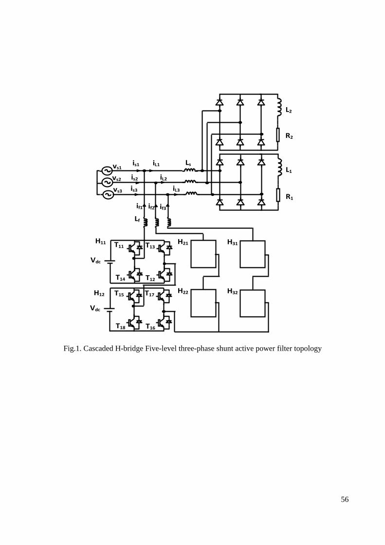
Fig. 1 presents the cascaded H-bridge five-level three-phase shunt active power filter
connected to balanced power grid (vsi for i = {1, 2, 3}) powering a three phase parallel-connected
two diode rectifiers feeding variable series (R, L) loads. The active filter is composed, in each
phase, of two voltage source H-bridge inverters (Hij, i=1,2,3, j=1,2) with 4 bidirectional switches
(transistor + diode) for each one. The filter is connected to the power grid through inductive filter
Lf for each phase. The output currents of shunt active filter are controlled to provide a similar
waveform of identified reactive and harmonic currents generated by the non-linear load (diode
rectifiers) [31], [32].
3. Harmonic current identification
Many harmonic current identification methods have been investigated by many researchers
such as synchronous detection method, average mode method, instantaneous active and reactive
powers method [33], [34] [35]. This latter was, which is widely used, was introduced by Akagi [35].
Fig. 2 presents a block diagram of instantaneous active and reactive powers harmonic currents
identification technique. The major advantage of this control principle is its simplicity and easiness
to be implemented. The main task of harmonic currents compensation is to determine the harmonic
current references to be generated by the active filter; then controlling the active filter to generate
the identified harmonic currents and inject them in the main electrical power grid.
56
Fig.1. Cascaded H-bridge Five-level three-phase shunt active power filter topology
iL1 is1
is2
vs1 Ls
Lf
Vdc
is3
if3
iL2
iL3
T11 T13
T14 T12
if2 if1
L1
R1
Vdc
T15 T17
T18 T16
H11
H12
vs2
vs3
H21
H22
H31
H32
L2
R2

57
Fig.2. Block diagram of the harmonic currents identification
By supposing that the main power supply voltages are sinusoidal, current harmonic references will
be calculated like indicated in [36].
(α, β) voltage components at coupling point of active filter (vα, vβ) and currents (iα, iβ) are defined
by the classical Concordia transformation:
1
1 1/ 2 1/ 2
2 23
0 3 / 2 3 / 2
3
x
x
x
x
x
(1)
Where x = {v, vs, i, iL}
The instantaneous real and imaginary powers, noted by p and q, are calculated by:
i
i
vv
vv
q
p
(2)
These powers are then filtered by high-pass filters, which gives ph and qh and the harmonic
components of the currents will be:
1
2 2 2
3
1 0
11/ 2 3 / 2
1/ 2 3 / 2
h h
h
h h
i v v p
iv v
i v v q
(3)

58
4. Comparison of fault detection in static converters
Recently, static converters behavior during an occurrence of faults in a static power switch or
in drivers as well as in topologies known as « Fault tolerant » have been subject to numerous works
and publications. Early in 1994, Kastha et Bose have presented a systematic study on the
consequences of voltage source invertrs defaults feeding an induction motor [37]. However they did
not present a method allowing the detection of these faults. Peuget et al have presented a method
allowing fault detection based on the trajectory path of the phase current vector [37]. Actually, in
normal condition (without faults), phase current vector in frame has a circle trajectory path.
When an open circuit fault occurs, caused by the failure of a static power switch remaining in open
state, within one leg of the inverter, the trajectory path becomes a semi-circle. The position of the
semi-circle in frame can be informative on the faulty power switch. Mendes et Cardoso have
proposed to use the phase current mean value in the stationary park frame in order to identify faults
of open circuit type [38]. The methods proposed above have been only applied to inverters feeding
induction motors and require at least one period of the phase current fundamental to detect faulty
operation.
Also, more recently, reduction of the required time to detect malfunction (delay between fault
apparition and its detection) has been investigated in several research papers. Ribeiro et al. have
proposed to use supplementary voltage sensors to detect open circuit and short circuit faults [39]
and [40]. They have shown that using the measurement of the three voltages between each
inverter’s phase and the voltage at midpoint of the capacitors divider of the DC source and their
comparison with the estimated voltages, fault can then be detected in quarter of the period of the
phase currents. Yu et al., Shamsi-Nejhad et al. have used voltage measurements of the switch
terminals at the bottom of each leg to detect faults, [41] and [42]. They also showed that from these
measured voltages and their comparison with a threshold, the fault can be detected in a period of the
fundamental phase currents. Table 1 compares the methods mentioned previously in terms of limits
of application, detection time and the number of additional required sensors.

59
Table.1. Comparison of defect detection methods at the power semiconductors (fundamental frequency of 50 Hz).
Method Principle Application
Limit
Detection
Time
Number.
Sensors
additional
Tracking the trajectory of the phase current vector [37] Machines
Power
> 20 ms -
Average value of the phase currents in the reference frame
Park [38]
Machines
Power
> 20 ms -
Voltage measurement "pole voltage" converter [39] - > 5 ms 3
Measuring the voltages across the switches [41] - > 5 ms 3
In the present work, a novel fault detection method of power switches or drivers used in a
three-phase five-level H-bridge voltage source inverter used as SAPF. The proposed method, based
on comparison of SAPF output voltages mean values to thresholds, allows detecting faults precisely
avoiding erroneous detection that follow state change of power switches.
5. Active filter fault diagnosis method
Several faulty cases can occur: power transistor or power transistor driver can be faulty. In
each case, it results in the following models:
- A transistor is closed instead of being normally open. It results in a short-circuit of the DC voltage
source. To isolate the faulty switch as fast as possible, one can use fuses.
- A transistor is open instead of being normally closed. The filter may continue injecting currents to
the power supply. These currents don't cause any prompt risk because they are at the same range
level as the case of no-fault condition. However, the filter, in this case, may pollute more the power
supply instead of elimination of harmonic currents of non-linear load. This case is considered in this
paper.
This section presents simulation results obtained with PSIM simulator for PWM controlled
cascaded H-bridge five-level three-phase shunt active power filter. Horizontally shifted carriers
PWM control technique is considered where reference signals are compared to 4 carriers shifted by
90° one to another to generate transistors control signal. Simulation parameters are:
- Main source grid: 220V, 50 Hz;

60
- Non-linear load: R1 = 10 Ohm for t ϵ [0,0.7sec], R1 = 5 Ohm for t ϵ [0.7,1.5sec], L1 = 0.005 H,
R2 = 1000 Ohm for t ϵ [0,1.1sec], R2 = 5 Ohm for t ϵ [1.1, 1.5sec], L2 = 0.01 H, Ls = 0.0015 H;
- Active filter: Vdc = 300 V, Lf = 0.004 H, fp = 5000 Hz (PWM carriers frequency), Proportional-
integral (PI) regulators: Gain kp = 0.5, time constant Ti = 0.001.
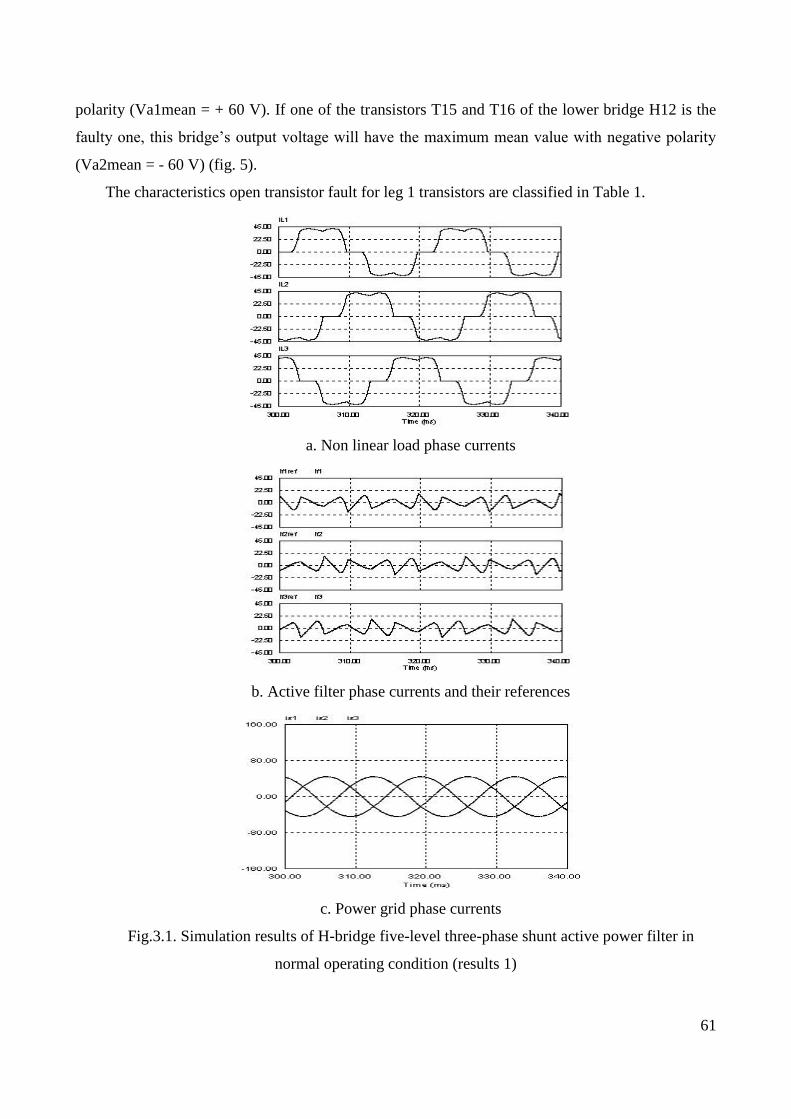
These parameters are chosen to reduce THD of main source currents below 5%. It is noticed
that filter output currents are superimposed to their harmonic identified reference currents and that
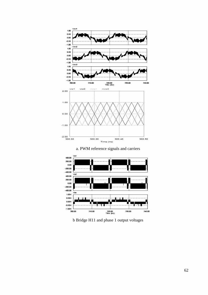
grid source currents are almost sinusoidal (fig. 3.1.b, fig. 3.1.c). It is also remarked that PI output
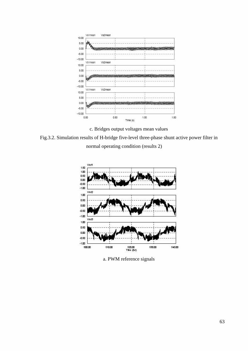
signals (PWM reference signals: Vref1, Vref2, Vref3) are symmetric (fig. 3.2.d) which produce
symmetric output voltages Va1 and Va2 (Vb1, Vb2, Vc1, Vc2 with a,b et c as phase indicators)
with small mean values Va1mean, Va2mean, Vb1mean, Vba2mean, Vc1mean, Vc2mean (fig. 3.2.e,
fig. 3.2.f).
Faulty phase, faulty bridge and more precisely, open faulty transistor detection is based on
the calculation of zero harmonic component (mean value, dc offset) included in H bridges output
voltages. This is done by using a second-order low-pass filter with cut-off frequency of 5 Hz and
damping ratio of 0.7.
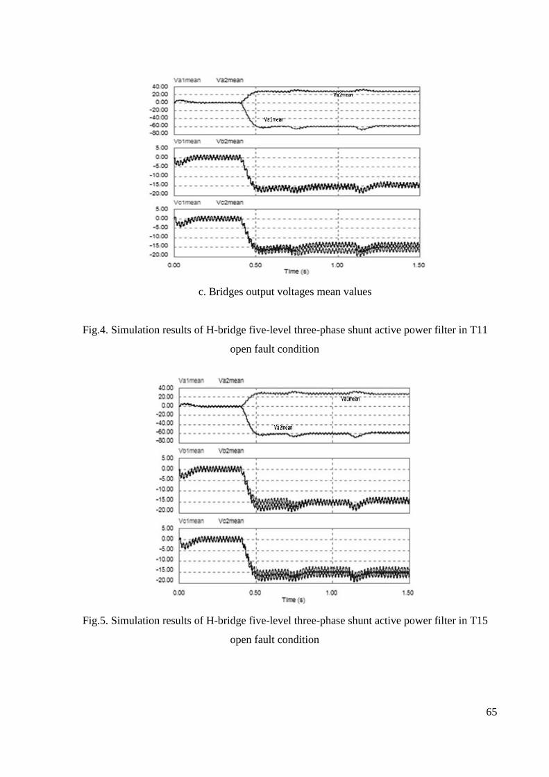
When a transistor is in open fault condition, the PI regulators will output a PWM reference signal in
a way to compensate the error due to that faulty transistor. In this case, PWM reference signals will
be asymmetric making H bridges output voltages asymmetric too with significant mean values
specific to each faulty transistor (fig.4).
A change in H bridges output voltages waveforms is defined as the instant at which a sudden
increase or decrease is observed in the DC offset component of these voltages. A change is
considered to have occurred in the H bridges output voltages mean values when they exceeds or
falls below a given band (fig. 4.c).
Phase 1 is linked to the first leg of inverter which is composed of upper bridge H11 and
lower bridge H12. If the open circuit faulty transistor belongs to leg 1, one of its bridges output
voltages will have the maximum mean value (Va1mean = ± 60 V or Va2mean = ± 60 V). If the
faulty transistor belongs to the upper bridge H11 (T11, T12, T13, T14), this latter’s output voltage
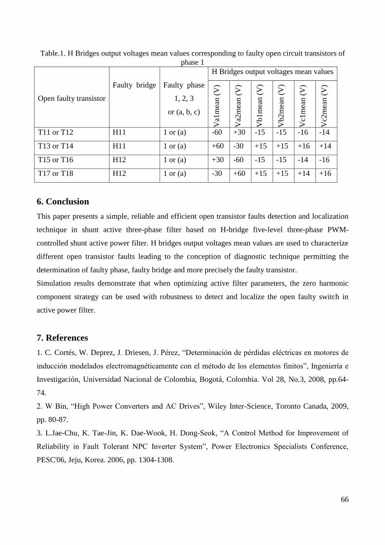
will have the maximum mean value (Va1mean = ± 60 V) (fig. 4). If the faulty transistor belongs to
the lower bridge H12 (T15, T16, T17, T18), this latter’s output voltage will have the maximum
mean value (Va2mean = ± 60 V) (fig. 5). If one of the transistors T11 and T12 of the upper bridge
H11 is the faulty one, this bridge’s output voltage will have the maximum mean value with negative
polarity (Va1mean = - 60 V) (fig. 4.c). If one of the transistors T13 and T14 of the upper bridge
H11 is the faulty one, this bridge’s output voltage will have the maximum mean value with positive
61
polarity (Va1mean = + 60 V). If one of the transistors T15 and T16 of the lower bridge H12 is the
faulty one, this bridge’s output voltage will have the maximum mean value with negative polarity
(Va2mean = - 60 V) (fig. 5).
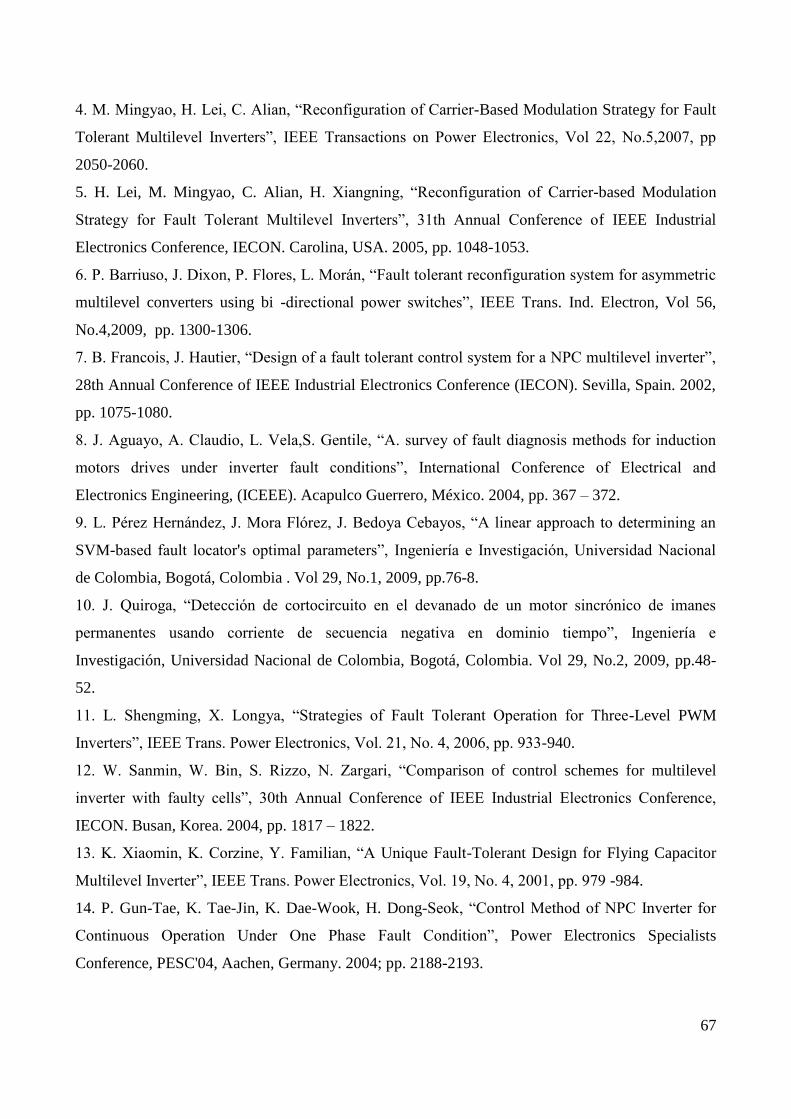
The characteristics open transistor fault for leg 1 transistors are classified in Table 1.
a. Non linear load phase currents
b. Active filter phase currents and their references
c. Power grid phase currents
Fig.3.1. Simulation results of H-bridge five-level three-phase shunt active power filter in
normal operating condition (results 1)
62
a. PWM reference signals and carriers
b Bridge H11 and phase 1 output voltages
63
c. Bridges output voltages mean values
Fig.3.2. Simulation results of H-bridge five-level three-phase shunt active power filter in
normal operating condition (results 2)
a. PWM reference signals
64
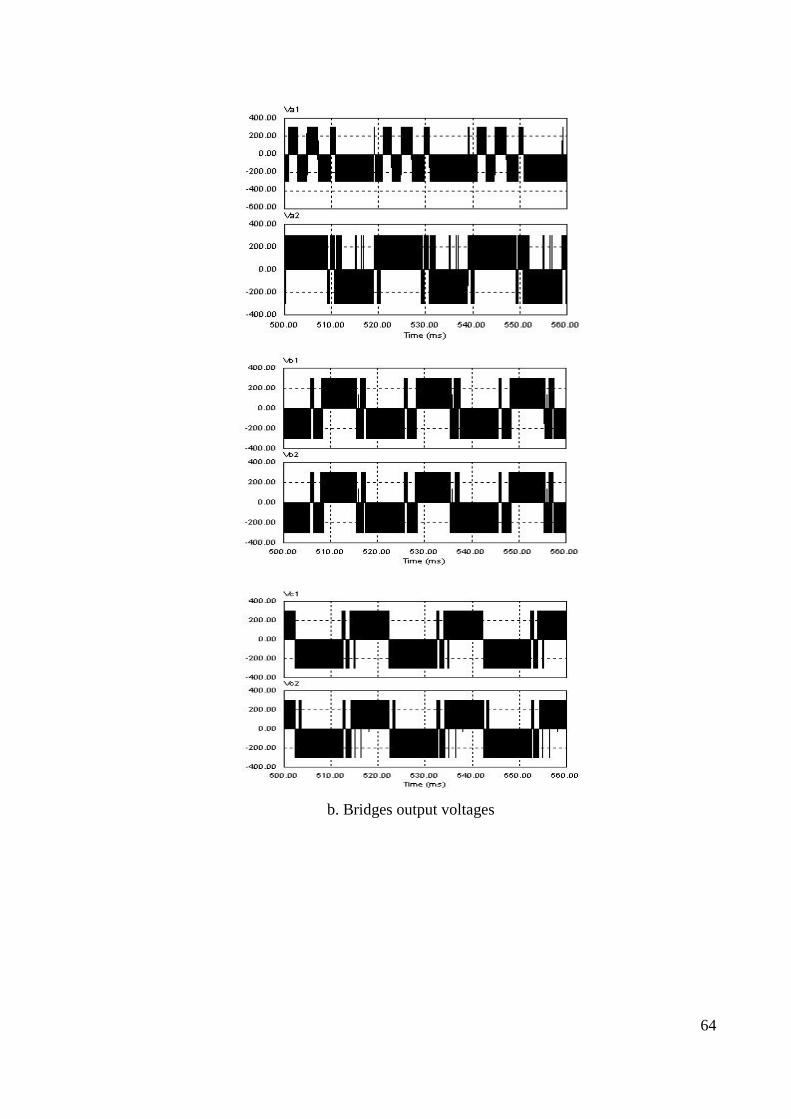
b. Bridges output voltages
65
c. Bridges output voltages mean values
Fig.4. Simulation results of H-bridge five-level three-phase shunt active power filter in T11
open fault condition
Fig.5. Simulation results of H-bridge five-level three-phase shunt active power filter in T15
open fault condition
66
Table.1. H Bridges output voltages mean values corresponding to faulty open circuit transistors of
phase 1
Open faulty transistor
Faulty bridge
Faulty phase
1, 2, 3
or (a, b, c)
H Bridges output voltages mean values
Va1
mea
n (
V)
Va2
mea
n (
V)
Vb1m
ean (
V)
Vb2m
ean (
V)
Vc1
mea
n (
V)
Vc2
mea
n (
V)
T11 or T12 H11 1 or (a) -60 +30 -15 -15 -16 -14
T13 or T14 H11 1 or (a) +60 -30 +15 +15 +16 +14
T15 or T16 H12 1 or (a) +30 -60 -15 -15 -14 -16
T17 or T18 H12 1 or (a) -30 +60 +15 +15 +14 +16
6. Conclusion
This paper presents a simple, reliable and efficient open transistor faults detection and localization
technique in shunt active three-phase filter based on H-bridge five-level three-phase PWM-
controlled shunt active power filter. H bridges output voltages mean values are used to characterize
different open transistor faults leading to the conception of diagnostic technique permitting the
determination of faulty phase, faulty bridge and more precisely the faulty transistor.
Simulation results demonstrate that when optimizing active filter parameters, the zero harmonic
component strategy can be used with robustness to detect and localize the open faulty switch in
active power filter.
7. References
1. C. Cortés, W. Deprez, J. Driesen, J. Pérez, “Determinación de pérdidas eléctricas en motores de
inducción modelados electromagnéticamente con el método de los elementos finitos”, Ingeniería e
Investigación, Universidad Nacional de Colombia, Bogotá, Colombia. Vol 28, No.3, 2008, pp.64-
74.
2. W Bin, “High Power Converters and AC Drives”, Wiley Inter-Science, Toronto Canada, 2009,
pp. 80-87.
3. L.Jae-Chu, K. Tae-Jin, K. Dae-Wook, H. Dong-Seok, “A Control Method for Improvement of
Reliability in Fault Tolerant NPC Inverter System”, Power Electronics Specialists Conference,
PESC'06, Jeju, Korea. 2006, pp. 1304-1308.
67
4. M. Mingyao, H. Lei, C. Alian, “Reconfiguration of Carrier-Based Modulation Strategy for Fault
Tolerant Multilevel Inverters”, IEEE Transactions on Power Electronics, Vol 22, No.5,2007, pp
2050-2060.
5. H. Lei, M. Mingyao, C. Alian, H. Xiangning, “Reconfiguration of Carrier-based Modulation
Strategy for Fault Tolerant Multilevel Inverters”, 31th Annual Conference of IEEE Industrial
Electronics Conference, IECON. Carolina, USA. 2005, pp. 1048-1053.
6. P. Barriuso, J. Dixon, P. Flores, L. Morán, “Fault tolerant reconfiguration system for asymmetric
multilevel converters using bi -directional power switches”, IEEE Trans. Ind. Electron, Vol 56,
No.4,2009, pp. 1300-1306.
7. B. Francois, J. Hautier, “Design of a fault tolerant control system for a NPC multilevel inverter”,
28th Annual Conference of IEEE Industrial Electronics Conference (IECON). Sevilla, Spain. 2002,
pp. 1075-1080.
8. J. Aguayo, A. Claudio, L. Vela,S. Gentile, “A. survey of fault diagnosis methods for induction
motors drives under inverter fault conditions”, International Conference of Electrical and
Electronics Engineering, (ICEEE). Acapulco Guerrero, México. 2004, pp. 367 – 372.
9. L. Pérez Hernández, J. Mora Flórez, J. Bedoya Cebayos, “A linear approach to determining an
SVM-based fault locator's optimal parameters”, Ingeniería e Investigación, Universidad Nacional
de Colombia, Bogotá, Colombia . Vol 29, No.1, 2009, pp.76-8.
10. J. Quiroga, “Detección de cortocircuito en el devanado de un motor sincrónico de imanes
permanentes usando corriente de secuencia negativa en dominio tiempo”, Ingeniería e
Investigación, Universidad Nacional de Colombia, Bogotá, Colombia. Vol 29, No.2, 2009, pp.48-
52.
11. L. Shengming, X. Longya, “Strategies of Fault Tolerant Operation for Three-Level PWM
Inverters”, IEEE Trans. Power Electronics, Vol. 21, No. 4, 2006, pp. 933-940.
12. W. Sanmin, W. Bin, S. Rizzo, N. Zargari, “Comparison of control schemes for multilevel
inverter with faulty cells”, 30th Annual Conference of IEEE Industrial Electronics Conference,
IECON. Busan, Korea. 2004, pp. 1817 – 1822.
13. K. Xiaomin, K. Corzine, Y. Familian, “A Unique Fault-Tolerant Design for Flying Capacitor
Multilevel Inverter”, IEEE Trans. Power Electronics, Vol. 19, No. 4, 2001, pp. 979 -984.
14. P. Gun-Tae, K. Tae-Jin, K. Dae-Wook, H. Dong-Seok, “Control Method of NPC Inverter for
Continuous Operation Under One Phase Fault Condition”, Power Electronics Specialists
Conference, PESC'04, Aachen, Germany. 2004; pp. 2188-2193.
68
15. F. Fuchs, “Some Diagnosis Methods for Voltage Source Inverters In Variable Speed Drives
with Induction Machines A Survey”, 29th Annual Conference of IEEE Industrial Electronics
Conference (IECON). Virginia, USA. 2003, pp. 1378 - 1385.
16. Z. Sun, J. Wang, D. Howe, G. Jewell, “Analytical prediction of short-circuit current in fault-
tolerant permanent magnet machines”, IEEE Trans. Ind. Electron., Vol. 57, No. 99, 2010, pp. 1-1.
17. W. Sanmin, W. Bin, L. Fahai, S. Xudong, “Control Method for Cascade H-Bridge Multilevel
Inverter with Faulty Power Cells”, Applied Power Electronics Conference and Exposition, APEC.
Miami Beach, Frorida, USA. Vol 9, No.1, 2003, pp. 261 – 267.
18. S. Khomfoi, L. Tolbert, “A Reconfiguration Technique for Multilevel Inverters Incorporating a
Diagnostic System Based on Neural Network”, Computers in Power Electronics, COMPEL. Troy,
New York, USA. July 2006, pp. 317-323.
19. L. De Lillo, L.Empringham, P. Wheeler, S. Khwan-On, “Multiphase power converter drive for
fault-tolerant machine development in aerospace application”, IEEE Trans. Ind. Electron., Vol 57,
No.2, 2010, pp. 575-583.
20. C. Thybo, “Fault-tolerant control of induction motor drive applications” Proceedings of the
American Control Conference, Vol 25, No.4, 2001, pp. 2621–2622.
21. Y. Xiong, X. Cheng, Z. Shen, M. Chunting,W. Hongjie, V. Garg, “Prognostic and Warning
System for Power-Electronic Modules in Electric”, Hybrid Electric, and Fuel-Cell Vehicles., IEEE
Trans. Ind. Electron, Vol 55, No.6, 2008, pp. 2268 -2276.
22. B. Lu, S. Sharma, “A literature review of IGBT fault diagnostic and protection methods for
power inverters”, IEEE Trans. Ind. Appl., Vol 45, No.5, 2009, pp. 1770 - 1777..
23. D. Kastha, B. Bose, “Investigation of fault modes of voltage-fed inverter system for induction
motor drive”, IEEE Transactions on Industry Applications. Vol 30, No.4,1994, pp. 1028-1038.
24. R. De Araujo Ribeiro, C.Jacobina, E. da Silva, A. Lima, “Fault detection of open-switch
damage in voltage-fed PWM motor drive systems”, IEEE Transactions on Power Electronics. Vol
18, No.2, 2003, pp. 587–593.
25. M. Beltrao de Rossiter Correa, C. Brandao Jacobina, E. Cabral da Silva, A. Nogueira Lima, “An
induction motor drive system with improved fault tolerance” IEEE Transactions on Industry
Applications. Vol 37, No.3, 2001, pp. 873–879.
26. C. Jacobina, M. Correa, R. Pinheiro, A. Lima, E. da Silva, “Improved fault tolerance of active
power filter system”, IEEE 32nd Annual Power Electronics Specialists Conference PESC 2001;
Vol. 3: pp17–21.
69
27. T. Benslimane, “Open Switch Faults Detection and Localization Algorithm for Three Phases
Shunt Active Power Filter Based on Two Level Voltage Source Inverter”, Elektronika ir
Elektrotechnika, Signal technology, Vol 74, No.2,2007, pp. 21- 24.
28. S. Khomfoi, “Fault diagnostic system for cascaded h-bridge multilevel inverter drives based on
artificial intelligent approaches incorporating a reconfiguration technique”, Doctorate thesis,
University of Tennessee, USA, 2007.
29. P. Pourea, P. Weberb, D. Theilliol, S. Saadate, “Fault tolerant control of a three-phase three-
wire shunt active filter system based on reliability analysis”, Electric Power Systems Research 79
,2009, pp 325–334.
30. S. Karimi, “Continuité de service des convertisseurs triphasés de puissance et prototypage
"FPGA in the loop": application au filtre actif parallèle”, Doctorate thesis, Henri Poincaré
University, Nancy-I, France.2009.
31. V. Kumar Chinnaiyan, J. Jovitha , J. Karpagam, “ Design, simulation, experimentation and
analysis of three-phase cascaded multilevel inverter with reduced power quality issues ”, AMSE
Journals, Modelling A, General Physics and Electrical Applications, Vol.83, Issue 2, 2010, pp.34-
46.
32. N. Devarajan, P. Maruthu Pandi, “ Harmonic reduction in SPWM based cascaded multilevel
inverter –A soft computing approach ”, AMSE Journals, Advances C, Automatic Control, Vol. 64,
Issue 2, 2009, pp. 58-77.
33. M.T Lamchich, H. Abaali, M. Raoufi, “ Average current mode to control the three-phase shunt
active power filters under distortedand unbalanced Voltage conditions ”, AMSE Journals,
Modelling A, General Physics and Electrical Applications, Vol.80, Issue 1, 2007, pp. 14-27.
34. M.T Lamchich, H. Abaali, M. Raoufi, “ Three-phase shunt active power filter control using
synchronous detection algorithm to compensate current perturbation ”, AMSE Journals, Modelling
A, General Physics and Electrical Applications, Vol.80, Issue 1, 2007, pp. 38-51.
35. H. Akagi, Y. Kanazawa, A. Nabae, “Generalized theory of the instantaneous reactive power
filter”, Proceedings of International power electronics conference, Tokyo, Japan, 1983; pp. 1375–
1386.
36. T. Benslimane, K. Aliouane, “A new optimized SVPWM Technique Control for Autonomous
Parallel Active Filter”, 11th International Conference on Harmonics and Quality of Power. – New
York , USA, IEEE Xplore, IEEE Transactions on Automatic Control. 2004, pp. 112–116.

70
37. R. Peuget, S. Courtine, J. Rognon, "Fault detection and isolation on a PWM inverter by
knowledge-based model", IEEE Transactions on Industry Applications, vol. 34, pp. 1318-1325,
1998.
38. A. M. S. Mendes, A. J. M. Cardoso, "Fault diagnosis in a rectifier – inverter system used in
variable speed AC drive, by the average current Park’s vector approach", European Power
Electronics Conference, Lausanne, pp. 1-9, 1999.
39. R.L.A. Ribeiro, C.B. Jacobina, E.R.C. da Silva, A.M.N. Lima, "A fault tolerant induction motor
drive system by using a compensation strategy on the PWM-VSI topology" IEEE Power Electronics
Specialists Conference, vol. 2, pp. 1191-1196, 2001.
40. R.L.A. Ribeiro, F. Profumo, C.B. Jacobina, G. Griva, E.R.C. da Silva, "Two fault tolerant
control strategies for shunt active power filter systems", IEEE International Conference on
Industrial Electronics, pp.792 – 797, 2002.
41. L. Ying; N. Ertugrul, "An observer-based three-phase current reconstruction using DC link
measurement in PMAC motors", International Power Electronics and Motion Control Conference,
vol. 1, pp. 1-5, Aug. 2006.
42. M.-A. Shamsi-Nejad, B. Nahid-Mobarakeh, S. Pierfederici, F. Meibody- Tabar, "Fault tolerant
and minimum loss control of double-star synchronous machines under open phase conditions",
IEEE Transactions on Industrial Electronics, vol. 55, no. 5, pp. 1956- 1965, May 2008.