operating instructions pressure sensor - ifm · 4 3 functions and features the unit monitors the...
TRANSCRIPT

Operating instructions Pressure sensor
PQ3xxxUK
8000
7230
/ 00
02
/ 20
14
2
Contents1 Preliminary note ���������������������������������������������������������������������������������������������������3
1�1 Symbols used ������������������������������������������������������������������������������������������������32 Safety instructions �����������������������������������������������������������������������������������������������33 Functions and features ����������������������������������������������������������������������������������������4
3�1 Use of the main connection G1/8 ������������������������������������������������������������������43�2 Use of the auxiliary connection M5 ����������������������������������������������������������������4
4 Function ���������������������������������������������������������������������������������������������������������������54�1 Output signals ������������������������������������������������������������������������������������������������54�2 Switching function ������������������������������������������������������������������������������������������54�3 IO-Link �����������������������������������������������������������������������������������������������������������6
4�3�1 General information ������������������������������������������������������������������������������64�3�2 Device-specific information �������������������������������������������������������������������64�3�3 Parameter setting tools �������������������������������������������������������������������������6
5 Installation������������������������������������������������������������������������������������������������������������75�1 Mounting accessories ������������������������������������������������������������������������������������75�2 DIN rail mounting �������������������������������������������������������������������������������������������75�3 Panel mounting ����������������������������������������������������������������������������������������������8
6 Electrical connection ��������������������������������������������������������������������������������������������87 Operating and display elements ��������������������������������������������������������������������������98 Menu ������������������������������������������������������������������������������������������������������������������10
8�1 Menu structure ���������������������������������������������������������������������������������������������108�2 Explanation of the menu ������������������������������������������������������������������������������ 11
9 Parameter setting ����������������������������������������������������������������������������������������������129�1 Parameter setting in general �����������������������������������������������������������������������129�2 Set output signals ����������������������������������������������������������������������������������������14
9�2�1 Set the unit of measurement for system pressure ������������������������������149�2�2 Set the output function ������������������������������������������������������������������������149�2�3 Set the switching limits (hysteresis function) ��������������������������������������149�2�4 Set the switching limits (window function) ������������������������������������������14
9�3 User settings (optional) ��������������������������������������������������������������������������������159�3�1 Set delay for the switching outputs �����������������������������������������������������159�3�2 Set damping for the switching outputs ������������������������������������������������15
3
UK
1 Preliminary note1.1 Symbols used
► Instruction> Reaction, result[…] Designation of pushbuttons, buttons or indications→ Cross-reference
Important note Non-compliance can result in malfunction or interference�
2 Safety instructions• Please read this document prior to set-up of the unit� Ensure that the product is
suitable for your application without any restrictions�• If the operating instructions or the technical data are not adhered to, personal
injury and/or damage to property can occur�• Check the compatibility of the product materials (see technical data) with the
media to be measured (see data sheet at www�ifm�com)�
9�3�3 Configuration of the display ����������������������������������������������������������������159�3�4 Zero-point calibration ��������������������������������������������������������������������������169�3�5 Differential pressure measurement: optimisation of the sensor accuracy �������������������������������������������������������������������������������������������������������16
9�4 Service functions �����������������������������������������������������������������������������������������169�4�1 Read min/max values for the system pressure ����������������������������������169�4�2 Reset all parameters to factory setting �����������������������������������������������17
10 Operation ���������������������������������������������������������������������������������������������������������1710�1 Read set parameters ���������������������������������������������������������������������������������1710�2 Error indications �����������������������������������������������������������������������������������������17
11 Technical data and scale drawing ��������������������������������������������������������������������1812 Factory setting �������������������������������������������������������������������������������������������������18
4
3 Functions and featuresThe unit monitors the system pressure/differential pressure in compressed air networks and pneumatic systems of machines and plants�
Avoid static and dynamic overpressure exceeding the specified overload pressure by taking appropriate measures�The indicated bursting pressure must not be exceeded�Even if the bursting pressure is exceeded only for a short time, the unit may be destroyed� ATTENTION: Risk of injury!Pressure Equipment Directive (PED): The units comply with section 3, article (3) of the Directive 97/23/EC and are designed and manufactured for media of fluid group 2 (stable gases and non-superheated liquids) in accordance with the sound engineering practice�
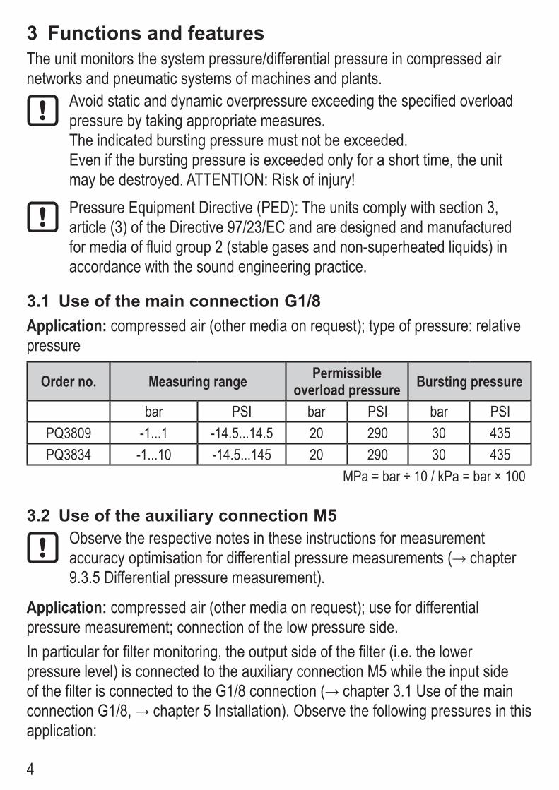
3.1 Use of the main connection G1/8Application: compressed air (other media on request); type of pressure: relative pressure
Order no. Measuring range Permissible overload pressure Bursting pressure
bar PSI bar PSI bar PSIPQ3809 -1���1 -14�5���14�5 20 290 30 435PQ3834 -1���10 -14�5���145 20 290 30 435
MPa = bar ÷ 10 / kPa = bar × 100
3.2 Use of the auxiliary connection M5Observe the respective notes in these instructions for measurement accuracyoptimisationfordifferentialpressuremeasurements(→chapter9�3�5 Differential pressure measurement)�
Application: compressed air (other media on request); use for differential pressure measurement; connection of the low pressure side�In particular for filter monitoring, the output side of the filter (i�e� the lower pressure level) is connected to the auxiliary connection M5 while the input side ofthefilterisconnectedtotheG1/8connection(→chapter3.1UseofthemainconnectionG1/8,→chapter5Installation).Observethefollowingpressuresinthisapplication:
5
UK
• Permissible overload pressure in the auxiliary connection as opposed to the main connection: 2 bar / 29 PSI�
• Bursting pressure of the auxiliary connection as opposed to the main connection: 12 bar / 174 PSI�
4 Function4.1 Output signals• The unit displays the current system pressure (with use of the main connection
G1/8 only) or the differential pressure (with additional use of the auxiliary connection M5)�
• It generates 2 output signals according to the parameter setting�OUT1 Switching signal for limit value / IO-LinkOUT2 Analogue output 4���20 mA (fixed across the measuring range of the sensor)
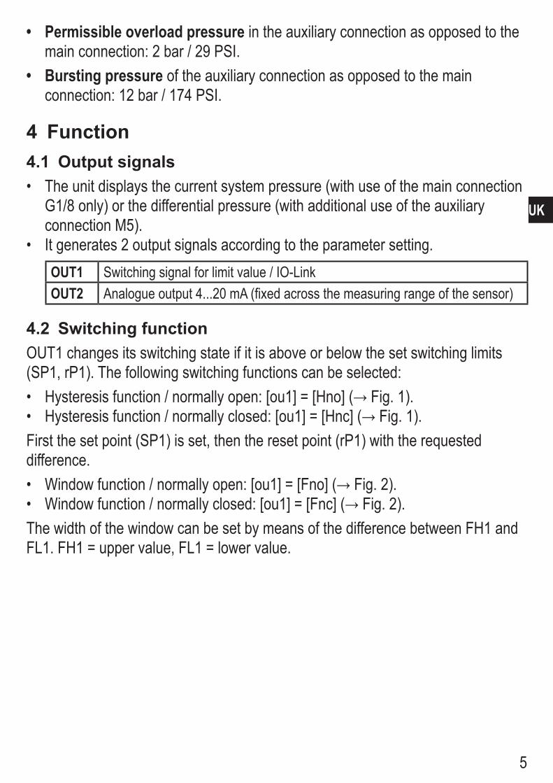
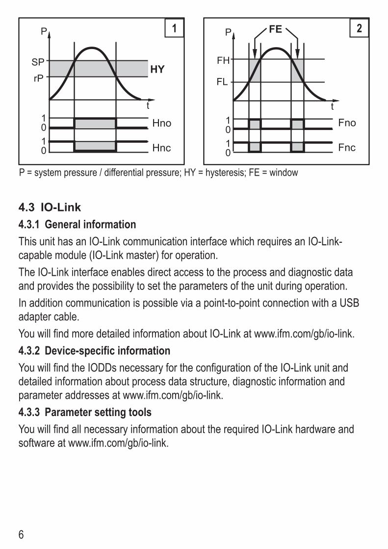
4.2 Switching functionOUT1 changes its switching state if it is above or below the set switching limits (SP1, rP1)� The following switching functions can be selected:• Hysteresisfunction/normallyopen:[ou1]=[Hno](→Fig.1).• Hysteresisfunction/normallyclosed:[ou1]=[Hnc](→Fig.1).First the set point (SP1) is set, then the reset point (rP1) with the requested difference�• Windowfunction/normallyopen:[ou1]=[Fno](→Fig.2).• Windowfunction/normallyclosed:[ou1]=[Fnc](→Fig.2).The width of the window can be set by means of the difference between FH1 and FL1� FH1 = upper value, FL1 = lower value�
6
�
�
��
��
����
���
���
��
�
�
��
��
����
��
���
���
1 2
P = system pressure / differential pressure; HY = hysteresis; FE = window
4.3 IO-Link4.3.1 General informationThis unit has an IO-Link communication interface which requires an IO-Link-capable module (IO-Link master) for operation�The IO-Link interface enables direct access to the process and diagnostic data and provides the possibility to set the parameters of the unit during operation�In addition communication is possible via a point-to-point connection with a USB adapter cable�You will find more detailed information about IO-Link at www�ifm�com/gb/io-link�4.3.2 Device-specific informationYou will find the IODDs necessary for the configuration of the IO-Link unit and detailed information about process data structure, diagnostic information and parameter addresses at www�ifm�com/gb/io-link� 4.3.3 Parameter setting toolsYou will find all necessary information about the required IO-Link hardware and software at www�ifm�com/gb/io-link�
7
UK
5 InstallationBefore installing and removing the unit: Make sure that no pressure is applied to the system�
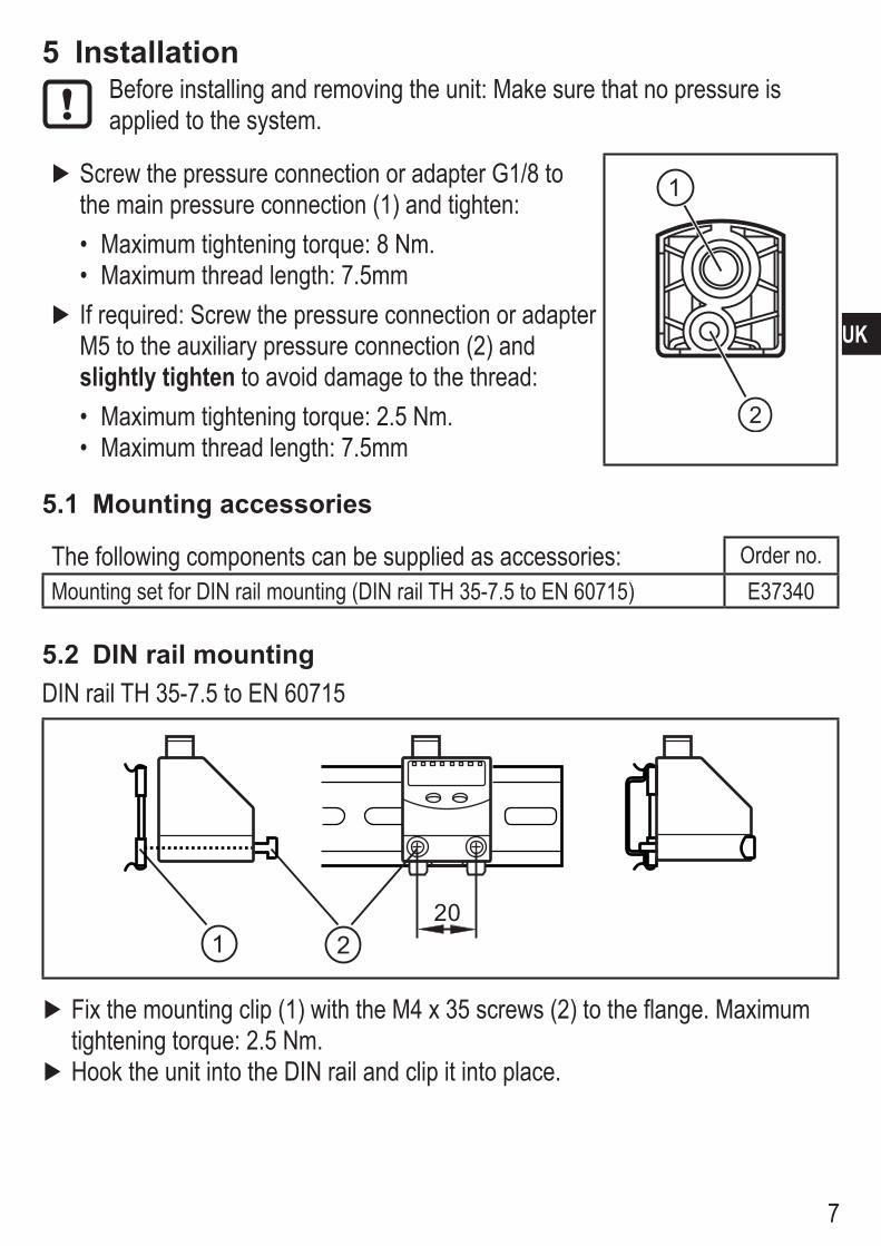
► Screw the pressure connection or adapter G1/8 to the main pressure connection (1) and tighten:• Maximum tightening torque: 8 Nm�• Maximum thread length: 7�5mm
► If required: Screw the pressure connection or adapter M5 to the auxiliary pressure connection (2) and slightly tighten to avoid damage to the thread:• Maximum tightening torque: 2�5 Nm�• Maximum thread length: 7�5mm
5.1 Mounting accessories
The following components can be supplied as accessories: Order no�Mounting set for DIN rail mounting (DIN rail TH 35-7�5 to EN 60715) E37340
5.2 DIN rail mountingDIN rail TH 35-7�5 to EN 60715
20
► Fix the mounting clip (1) with the M4 x 35 screws (2) to the flange� Maximum tightening torque: 2�5 Nm�
► Hook the unit into the DIN rail and clip it into place�
8
Removal: ► Lever out the mounting clip with a screwdriver at the top or at the bottom and remove the unit�
5.3 Panel mounting
20
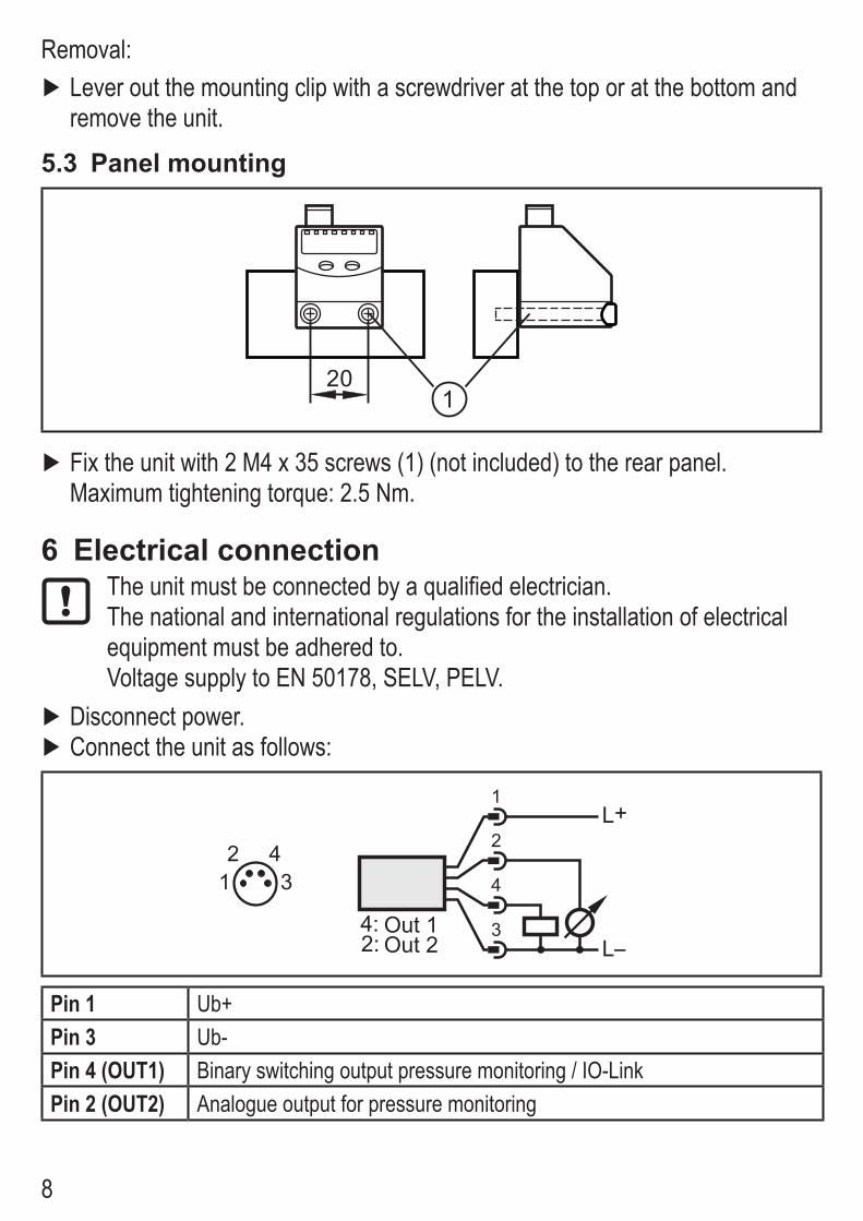
► Fix the unit with 2 M4 x 35 screws (1) (not included) to the rear panel� Maximum tightening torque: 2�5 Nm�
6 Electrical connectionThe unit must be connected by a qualified electrician�The national and international regulations for the installation of electrical equipment must be adhered to�Voltage supply to EN 50178, SELV, PELV�
► Disconnect power� ► Connect the unit as follows:
21
43
L+
LOut 2Out 1
2:4: 3
4
2
1
Pin 1 Ub+Pin 3 Ub-Pin 4 (OUT1) Binary switching output pressure monitoring / IO-LinkPin 2 (OUT2) Analogue output for pressure monitoring

9
UK
7 Operating and display elements1 2 3 4 5 6 7 8
10
9
11
Mode/Enter Set
1 to 8: Indicator LEDs - LED 1 to LED 4 = system pressure / differential pressure in the unit of measurement which is indicated on the label�
- LEDs 5, 6, 7: not used� - LED 8 = switching status of the output
9: Alphanumeric display, 4 digits - Display of the current system pressure� - Indication of the parameters and parameter values�
10: Set button - Setting of the parameter values (scrolling by holding pressed; incrementally by pressing once)�
11: Mode/Enter button - Selection of the parameters and acknowledgement of the parameter values�
10
8 Menu8.1 Menu structure
S
MM
S
MM
S
MM
S
MS
M
MS
M
MS
M
MM
SM
MS
MS
M
MM
S
MM
S
RUN
M
M
MS
M
MS
M
MS
M
MM
S
11
UK
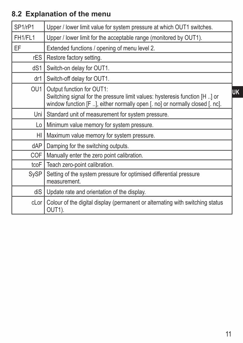
8.2 Explanation of the menu
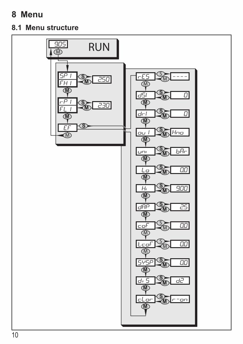
SP1/rP1 Upper / lower limit value for system pressure at which OUT1 switches�FH1/FL1 Upper / lower limit for the acceptable range (monitored by OUT1)�EF Extended functions / opening of menu level 2�
rES Restore factory setting�dS1 Switch-on delay for OUT1�dr1 Switch-off delay for OUT1�
OU1 Output function for OUT1:Switching signal for the pressure limit values: hysteresis function [H ��] or window function [F ��], either normally open [� no] or normally closed [� nc]�
Uni Standard unit of measurement for system pressure�Lo Minimum value memory for system pressure�HI Maximum value memory for system pressure�
dAP Damping for the switching outputs�COF Manually enter the zero point calibration�tcoF Teach zero-point calibration�
SySP Setting of the system pressure for optimised differential pressure measurement�
diS Update rate and orientation of the display�cLor Colour of the digital display (permanent or alternating with switching status
OUT1)�
12
9 Parameter settingDuring parameter setting the unit remains in the operating mode� It continues to monitor with the existing parameters until the parameter setting has been completed�
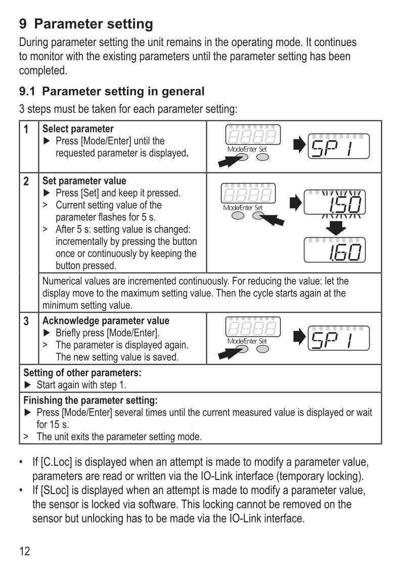
9.1 Parameter setting in general3 steps must be taken for each parameter setting:
1 Select parameter ► Press [Mode/Enter] until the requested parameter is displayed. ���������� ���
2 Set parameter value ► Press [Set] and keep it pressed�
> Current setting value of the parameter flashes for 5 s�
> After 5 s: setting value is changed: incrementally by pressing the button once or continuously by keeping the button pressed�
���������� ���
Numerical values are incremented continuously� For reducing the value: let the display move to the maximum setting value� Then the cycle starts again at the minimum setting value�
3 Acknowledge parameter value ► Briefly press [Mode/Enter]�
> The parameter is displayed again� The new setting value is saved�
���������� ���
Setting of other parameters: ► Start again with step 1�
Finishing the parameter setting: ► Press [Mode/Enter] several times until the current measured value is displayed or wait for 15 s�
> The unit exits the parameter setting mode�
• If [C�Loc] is displayed when an attempt is made to modify a parameter value, parameters are read or written via the IO-Link interface (temporary locking)�
• If [SLoc] is displayed when an attempt is made to modify a parameter value, the sensor is locked via software� This locking cannot be removed on the sensor but unlocking has to be made via the IO-Link interface�
13
UK
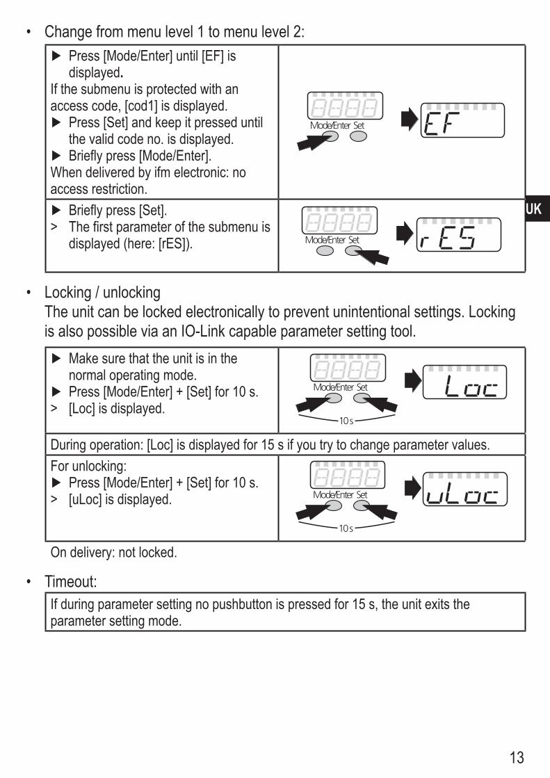
• Change from menu level 1 to menu level 2: ► Press [Mode/Enter] until [EF] is displayed.
If the submenu is protected with an access code, [cod1] is displayed�
► Press [Set] and keep it pressed until the valid code no� is displayed�
► Briefly press [Mode/Enter]�When delivered by ifm electronic: no access restriction�
���������� ���
► Briefly press [Set]� > The first parameter of the submenu is
displayed (here: [rES])� ���������� ���
• Locking / unlockingThe unit can be locked electronically to prevent unintentional settings� Locking is also possible via an IO-Link capable parameter setting tool�
► Make sure that the unit is in the normal operating mode�
► Press [Mode/Enter] + [Set] for 10 s� > [Loc] is displayed�
���������� ���
����
During operation: [Loc] is displayed for 15 s if you try to change parameter values�For unlocking:
► Press [Mode/Enter] + [Set] for 10 s� > [uLoc] is displayed� ���������� ���
����
On delivery: not locked�
• Timeout:If during parameter setting no pushbutton is pressed for 15 s, the unit exits the parameter setting mode�

14
9.2 Set output signals9.2.1 Set the unit of measurement for system pressure
► Select [uni] and set the unit of measurement:[bAr], [kPa], [PSi], [inHg]�
9.2.2 Set the output function ► Select [ou1] and set the function:
- [Hno] = hysteresis function/normally open, - [Hnc] = hysteresis function/normally closed, - [Fno] = window function/normally open, - [Fnc] = window function/normally closed�
9.2.3 Set the switching limits (hysteresis function) ► Make sure that for [ou1] the function [Hno] or [Hnc] is set� ► Select [SP1] and set the value at which the output switches� ► Select [rP1] and set the value at which the output switches off�
rP1 is always smaller than SP1� The unit only accepts values which are lower than SP1�
9.2.4 Set the switching limits (window function) ► Make sure that for [ou1] the function [Fno] or [Fnc] is set� ► Select [FH1] and set the upper limit of the acceptable range� ► Select [FL1] and set the lower limit of the acceptable range�
FL1 is always lower than FH1� The unit only accepts values which are lower than the value for FH1�
15
UK
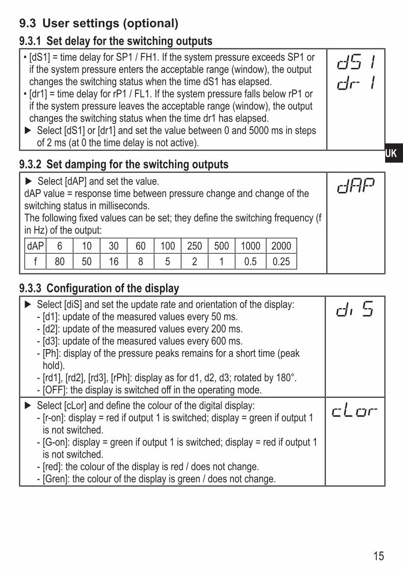
9.3 User settings (optional)9.3.1 Set delay for the switching outputs•[dS1] = time delay for SP1 / FH1� If the system pressure exceeds SP1 or
if the system pressure enters the acceptable range (window), the output changes the switching status when the time dS1 has elapsed�
•[dr1] = time delay for rP1 / FL1� If the system pressure falls below rP1 or if the system pressure leaves the acceptable range (window), the output changes the switching status when the time dr1 has elapsed� ► Select [dS1] or [dr1] and set the value between 0 and 5000 ms in steps of 2 ms (at 0 the time delay is not active)�
9.3.2 Set damping for the switching outputs ► Select [dAP] and set the value�
dAP value = response time between pressure change and change of the switching status in milliseconds�The following fixed values can be set; they define the switching frequency (f in Hz) of the output:dAP 6 10 30 60 100 250 500 1000 2000
f 80 50 16 8 5 2 1 0�5 0�25
9.3.3 Configuration of the display ► Select [diS] and set the update rate and orientation of the display:
- [d1]: update of the measured values every 50 ms� - [d2]: update of the measured values every 200 ms� - [d3]: update of the measured values every 600 ms� - [Ph]: display of the pressure peaks remains for a short time (peak hold)�
- [rd1], [rd2], [rd3], [rPh]: display as for d1, d2, d3; rotated by 180°� - [OFF]: the display is switched off in the operating mode�
► Select [cLor] and define the colour of the digital display: - [r-on]: display = red if output 1 is switched; display = green if output 1 is not switched�
- [G-on]: display = green if output 1 is switched; display = red if output 1 is not switched�
- [red]: the colour of the display is red / does not change� - [Gren]: the colour of the display is green / does not change�
16
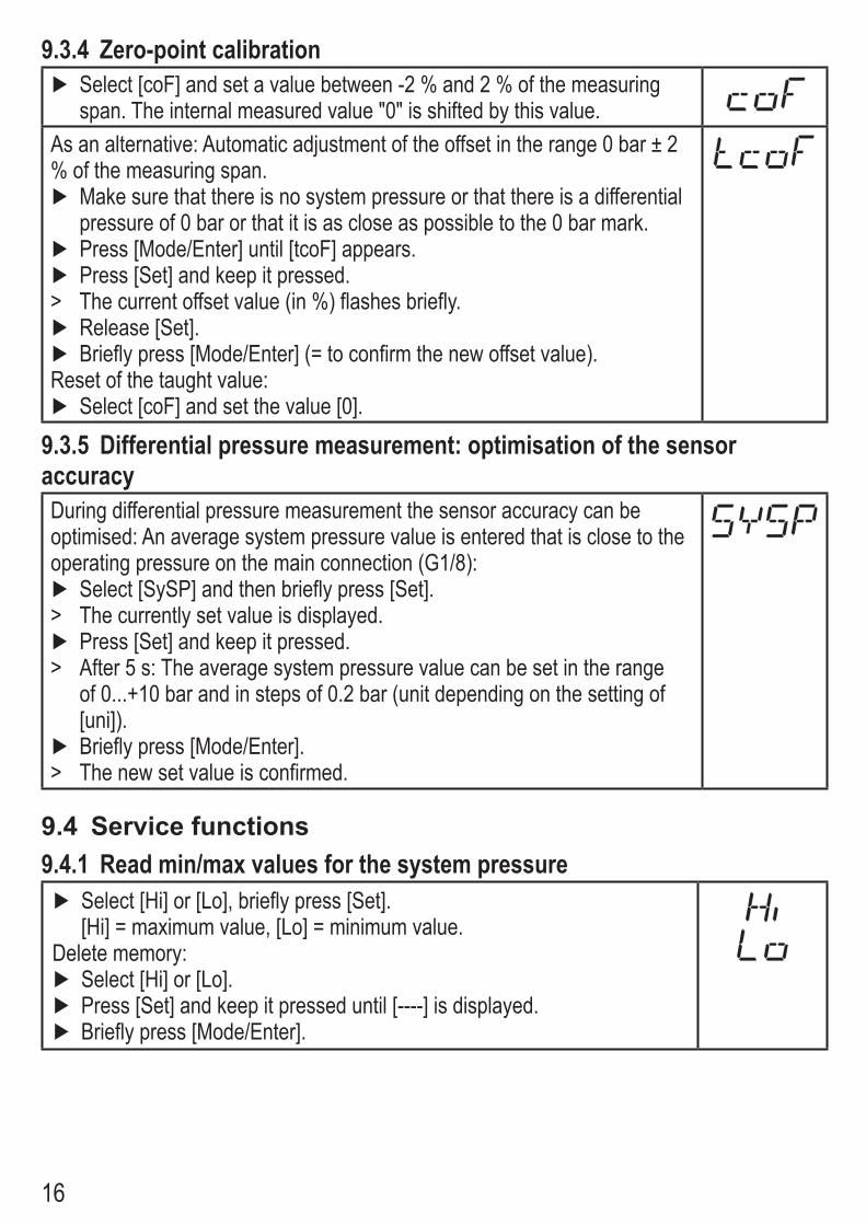
9.3.4 Zero-point calibration ► Select [coF] and set a value between -2 % and 2 % of the measuring span� The internal measured value "0" is shifted by this value�
As an alternative: Automatic adjustment of the offset in the range 0 bar ± 2 % of the measuring span�
► Make sure that there is no system pressure or that there is a differential pressure of 0 bar or that it is as close as possible to the 0 bar mark�
► Press [Mode/Enter] until [tcoF] appears� ► Press [Set] and keep it pressed�
> The current offset value (in %) flashes briefly� ► Release [Set]� ► Briefly press [Mode/Enter] (= to confirm the new offset value)�
Reset of the taught value: ► Select [coF] and set the value [0]�
9.3.5 Differential pressure measurement: optimisation of the sensor accuracyDuring differential pressure measurement the sensor accuracy can be optimised: An average system pressure value is entered that is close to the operating pressure on the main connection (G1/8):
► Select [SySP] and then briefly press [Set]� > The currently set value is displayed� ► Press [Set] and keep it pressed�
> After 5 s: The average system pressure value can be set in the range of 0���+10 bar and in steps of 0�2 bar (unit depending on the setting of [uni])�
► Briefly press [Mode/Enter]� > The new set value is confirmed�
9.4 Service functions9.4.1 Read min/max values for the system pressure
► Select [Hi] or [Lo], briefly press [Set]�[Hi] = maximum value, [Lo] = minimum value�
Delete memory: ► Select [Hi] or [Lo]� ► Press [Set] and keep it pressed until [----] is displayed� ► Briefly press [Mode/Enter]�
17
UK
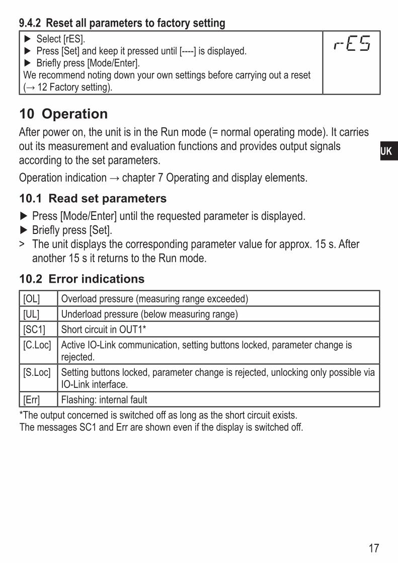
9.4.2 Reset all parameters to factory setting ► Select [rES]� ► Press [Set] and keep it pressed until [----] is displayed� ► Briefly press [Mode/Enter]�
We recommend noting down your own settings before carrying out a reset (→12Factorysetting).
10 OperationAfter power on, the unit is in the Run mode (= normal operating mode)� It carries out its measurement and evaluation functions and provides output signals according to the set parameters�Operationindication→chapter7Operatinganddisplayelements.
10.1 Read set parameters ► Press [Mode/Enter] until the requested parameter is displayed� ► Briefly press [Set]�
> The unit displays the corresponding parameter value for approx� 15 s� After another 15 s it returns to the Run mode�
10.2 Error indications[OL] Overload pressure (measuring range exceeded)[UL] Underload pressure (below measuring range)[SC1] Short circuit in OUT1*[C�Loc] Active IO-Link communication, setting buttons locked, parameter change is
rejected�[S�Loc] Setting buttons locked, parameter change is rejected, unlocking only possible via
IO-Link interface�[Err] Flashing: internal fault
*The output concerned is switched off as long as the short circuit exists�The messages SC1 and Err are shown even if the display is switched off�
18
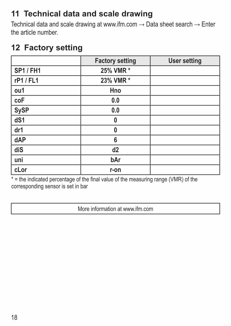
11 Technical data and scale drawingTechnicaldataandscaledrawingatwww.ifm.com→Datasheetsearch→Enterthe article number�
12 Factory settingFactory setting User setting
SP1 / FH1 25% VMR *rP1 / FL1 23% VMR *ou1 HnocoF 0.0SySP 0.0dS1 0dr1 0dAP 6diS d2uni bArcLor r-on
* = the indicated percentage of the final value of the measuring range (VMR) of the corresponding sensor is set in bar
More information at www�ifm�com

19
UK