orbital drilling of titanium alloys for aeronautics ... · orbital drilling of titanium alloys for...
TRANSCRIPT

Orbital drilling of Titanium alloys for aeronautics applications. Experimental studies
Nuno Filipe Morais Neto
Master´s Dissertation
Supervisors: Prof. Dr. Abílio Manuel Pinho de Jesus
Prof. Dr. Rui Jorge de Lemos Neto
Prof. Eng. Santiago David Castellanos Villa
Integrated Masters in Mechanical Engineering
February 2017


Orbital drilling of titanium alloys for aeronautics applications. Experimental studies
i
To my dear family and friends

Orbital drilling of Titanium alloys for aeronautics applications. Experimental studies
ii

Orbital drilling of Titanium alloys for aeronautics applications. Experimental studies
iii
Orbital drilling of Titanium alloys for aeronautics applications. Experimental studies Abstract
Orbital drilling consists in a helical milling process that has been adopted in aerospace
industry to manufacture high precision holes in components made of Titanium, Aluminium,
CFRP or combinations of such materials. Advantages can be appointed to the orbital drilling
process, namely it allows to efficient chip removal preventing heat build-up, minimizes chip
induced damage, makes cooling efficient due to intermittent cutting and generates low thrust
forces allowing burr-less drilling in metals or delamination-free drilling of composites.
Compared to conventional drilling, orbital drilling is controlled by a higher number of
cutting parameters, which makes the experimental studies more extensive. Thus, in this thesis,
experimental orbital drilling tests in Ti-6Al-4V plates were performed aiming at investigating
the cutting loads applied to the workpiece, the chip and burr formation, the diameter deviation,
the surface finishing and the tool wear, varying input machining parameters. Experimental tests
without lubrication (dry machining) were considered, which is a machining strategy with
evident environmental advantages and may represent significant reduction in the production
costs and opens the possibility to machine composite and multi-layer materials.
Taguchi design of experiments was used to reduce significantly the number of
experimental tests. The treatment of the results was performed resorting to Super Anova
software which made the analysis of variance (ANOVA) and mean analysis in order to identify
the input cutting parameters that most influence the dependent variables of the process, and to
assess their influence on the variations of the dependent variables. Therefore, the performed
analysis will potentially allow identifying the best level of the selected control factors that may
lead to the best performance of the manufacturing process, in particular the orbital drilling
process.
After the experimental work and results analysis, it was noticed that the discontinuous
cut (in-plane directions) originates shorter and thicker chip fragments, while the discontinuous
cut (axial direction) creates thinner and longer chips. No obvious consistent burr was created
either at the entrance or exit of the hole. Furthermore, the smallest values of the cutting
parameters (cutting speed, feed/tooth, axial feed) lead to the minimum diameter deviation.
Moreover, the magnitude of the roughness values was in the same range of typical polishing
techniques. Finally, the lowest in-plane cutting forces can be obtained with the selection of

Orbital drilling of Titanium alloys for aeronautics applications. Experimental studies
iv
higher cutting speeds combined with lower axial feed and feed/tooth, while the thrust force and
torque increases when the axial feed increments. Dry machining revealed a realistic machining
condition for orbital drilling of Ti6Al4V alloys.

Orbital drilling of Titanium alloys for aeronautics applications. Experimental studies
v
Fresagem orbital de ligas de Titânio para aplicações em aeronáutica. Estudo experimental Resumo A furação orbital consiste num processo de fresagem helicoidal adotada pela indústria
aeroespacial no âmbito do fabrico de furos de alta precisão em componentes de Titânio,
Alumínio, CFRP ou combinações desses materiais. Várias vantagens são apontadas ao processo
de furação orbital, nomeadamente permite uma remoção eficiente das aparas prevenindo a
concentração de calor, minimiza os danos induzidos pelas aparas, o corte intermitente leva a
um arrefecimento eficiente gerando menores forças de corte na direção axial do furo permitindo
uma furação aproximadamente livre de rebarba no caso dos metais e livre de delaminação nos
compósitos.
Comparativamente ao processo de furação convencional, a furação orbital é controlada
por um maior número de parâmetros de corte, o que faz com que estudos experimentais sejam
mais extensos. Deste modo, nesta dissertação, foram efetuados testes de furação orbital em
provetes de Ti-6Al-4V, investigando os esforços de corte aplicados na peça, a formação de
apara e rebarba, o desvio do diâmetro do furo, o acabamento superficial e o desgaste da
ferramenta, variando os parâmetros de maquinagem. Além disso, foram realizados ensaios sem
lubrificação, o que é considerada uma estratégia de maquinagem com vantagens ambientais
evidentes, reduz os custos de produção e abre a possibilidade à maquinagem de compósitos e
materiais compostos por multicamadas.
O planeamento dos ensaios pelo método de Taguchi reduziu significativamente o
número de ensaios experimentais. O tratamento dos resultados foi feito recorrendo ao software
Super Anova que fez a análise de variância (ANOVA) e a análise de médias a fim de identificar
os parâmetros de corte que mais influenciam as variações nas variáveis dependentes. Assim
sendo, essa análise permitirá identificar o melhor nível dos fatores de controlo selecionados que
podem levar ao melhor desempenho do processo de fabrico, em particular o processo de furação
orbital.
Depois da realização dos ensaios experimentais e da análise dos respetivos resultados,
notou-se que o corte descontínuo na direção do plano origina aparas curtas e espessas, enquanto
o corte descontínuo na direção axial cria aparas finas e curtas. Além disso, não houve uma
formação evidente de rebarba, tanto na entrada como na saída do furo e, concluiu-se que os
valores mais baixos dos parâmetros de corte (velocidade de corte, avanço por dente e avanço
axial) levam ao menor desvio no diâmetro do furo. Por sua vez, os valores das rugosidades
obtidas estão na mesma ordem dos processos de acabamento. Por fim, verificou-se que forças

Orbital drilling of Titanium alloys for aeronautics applications. Experimental studies
vi
de corte no plano mais baixas podem ser obtidas selecionando uma combinação de velocidades
de corte elevadas com avanços tangenciais e axiais baixos, enquanto que, tanto o esforço axial
como o binário aumentam com o aumento dos avanços (axial e tangencial). A maquinagem a
seco revelou ser uma condição realista para furação orbital de ligas Ti-6Al-4V.

vii
Acknowledgements First of all, I would like to thank Prof. Dr. Abílio de Jesus for all the help, guidance and
support during the research, experimental work and writing of this dissertation. He was always
helpful and did it the best way as possible. His patience, dedication, sympathy, motivation and
wisdom, made him a person I will always admire.
I would like to express my gratitude to my colleague Rui Soares that was always helpful
in everything I needed. He was fully involved in this study helping me with the experimental
work.
I would like to thank to Prof. Miguel Figueiredo whose help was crucial in the analysis
of the experimental work based on the Taguchi DOE.
I am very grateful to Santiago Villa, for his support and supervision during the work
and particularly for the support in the machining tests, including the CAM issues and machine
operation.
To Dr. Ramiro, Mrs. Armanda and all the INEGI Staff, I am sincerely thankful for all
the help and excellent working conditions provided.
I also want to express my gratitude to INEGI and particularly to UTAF research unit
and to the DEMec from the Faculty of Engineering for all work conditions they provided to me.
The funding of Project NORTE-01-0145-FEDER-000022 - SciTech, co-financed by
NORTE2020, through FEDER is acknowledged. Also, the METALCUT/LAETA project is
acknowledged.
At last, I must express my very deep gratitude to my parents, my sister, my girlfriend,
the rest of my family and friends for providing me the best support I could have during the
realization of this master thesis and everything in my life. All my motivation and dedication, in
part, was for them so they could be proud of me as much as I am of them. Thank you.

viii
ix
Table of Contents
1 INTRODUCTION ................................................................................................................... 1
1.1 PROJECT’S FRAMEWORK AND MOTIVATION ..................................................................... 1
1.2 OBJECTIVES ..................................................................................................................... 2
1.3 PROJECT’S METHODOLOGY .............................................................................................. 2
1.4 THESIS OUTLINE .............................................................................................................. 4
2 STATE OF THE ART ........................................................................................................ 5
2.1 METALLURGY OF TITANIUM ............................................................................................ 6
2.1.1Alpha (α) alloys .......................................................................................................... 6
2.1.2 Betta (β) alloys .......................................................................................................... 7
2.1.3 Alpha-Beta (α-β) alloys ............................................................................................. 7
2.2 TITANIUM AND ITS MACHINABILITY ................................................................................ 7
2.2.1 Material groups of the workpiece ............................................................................ 10
2.2.2 Cutting Tools Materials ........................................................................................... 12
2.2.3 Tool coatings ........................................................................................................... 13
2.3 MILLING ........................................................................................................................ 14
2.3.1Types of milling ....................................................................................................... 14
2.3.2 Basic definitions in milling process ........................................................................ 18
2.3.3 Milling direction ...................................................................................................... 19
2.4 ORBITAL DRILLING PROCESS .......................................................................................... 21
2.4.1Orbital drilling vs conventional drilling ................................................................... 21
2.4.2 Orbital Drilling Kinematics ..................................................................................... 23
2.4.3 Chip formation ......................................................................................................... 26
2.4.4 Lubrication .............................................................................................................. 28
2.4.5 Cutting Forces ......................................................................................................... 30
2.4.6 Burr formation ......................................................................................................... 33
2.4.7 Tool life ................................................................................................................... 34
3 EXPERIMENTAL DETAILS .......................................................................................... 39
3.1 TOOL AND HOLE DIAMETER ........................................................................................... 41
3.2 MATERIAL CHARACTERIZATION FOR ORBITAL DRILLING TESTS ..................................... 45
3.3 TOOL MEASUREMENT .................................................................................................... 46
3.4 CUTTING FORCES MEASUREMENT AND DATA ACQUISITION ............................................ 48
3.5 EXPERIMENTAL SETUP .................................................................................................. 48
x
3.6 SURFACE ROUGHNESS MEASUREMENT ........................................................................... 52
3.7 MACHINING PARAMETERS ............................................................................................... 53
3.8 EXPERIMENTAL METHOGOLOGY - TAGUCHI’S DOE ..................................................... 54
4 EXPERIMENTAL RESULTS ......................................................................................... 59
4.1 CUTTING FORCES ........................................................................................................... 59
4.2 CHIP FORMATION ........................................................................................................... 71
4.3 BURR FORMATION ......................................................................................................... 75
4.4 DIAMETER DEVIATION ................................................................................................... 76
4.5 ROUGHNESS ................................................................................................................... 77
4.6 TOOL WEAR ................................................................................................................... 80
5 TAGUCHI’S DOE ANALYSIS ....................................................................................... 81
5.1 DIAMETER ANALYSIS ..................................................................................................... 82
5.2 IN-PLANE FORCES ANALYSIS .......................................................................................... 86
5.3 THRUST FORCE .............................................................................................................. 92
5.4 TORQUE ANALYSIS ........................................................................................................ 94
5.5 SURFACE ROUGHNESS ANALYSIS ................................................................................... 96
6 CONCLUSIONS AND FUTURE WORK ....................................................................... 99
6.1 CONCLUSIONS ............................................................................................................... 99
6.2 FUTURE WORK ............................................................................................................. 101
7 REFERENCES ............................................................................................................... 103
8 ANNEX A – EXPERIMENTAL RESULTS ................................................................. 109
9 ANNEX B – ANOVA AND MEAN ANALYSIS RESULTS – MEANS GRAPHS .... 127
10 ANNEX C - ANOVA AND MEAN ANALYSIS RESULTS – MEANS TABLES ..... 141
xi
Symbols and Abbreviations
a Axial feed per orbital revolution
ae Radial length of cut
Al Aluminium
ANOVA Variance analysis
ap Axial depth of cut
BS Wiper edge length
BUE Built-up edge
C Carbon
CAD Computer-aided design
CAM Computer-aided manufacturing
CBN Cubic boron nitride
CFRP Carbon fibre reinforced plastics
CNC Computer numerical control
Cu Copper
DAQ Data acquisition
Dh Hole Diameter
Dt Tool Diameter
df degrees of freedom
DOE Design of experiment
fa Feed rate/tooth axial
fn Feed rate per rotation
fx In-plane force
fy In-plane force
fz Thrust force
hex Maximum chip thickness
kr Positioning angle
LE Cutting edge effective length
Mo Molybdenum
MQL Minimum quantity lubrication
MQLPO Minimum quantity lubrication palm oil
MQLSE Minimum quantity lubrication synthetic ester
Mz Torque
n Spindle rotation speed
N Nitrogen

xii
Nb Niobium
np Revolutionary speed
O Oxygen
P Contribution percentage
P-value Value of proof
Pc Power
PCBN Polycrystalline cubic boron nitride
PCD Polycrystalline diamond
Q Material’s removal rate
RE Corner radius
Si Silicon
st Feed rate per tooth tangential
Sn Tin
S Insert thickness
t Time
Tc Machining time
te Estimated machining time
TiC Titanium carbine
Ts Thickness of the specimen
V Vanadium
VB Average flank wear
vc Cutting speed
vf Feed rate
vfa Axial feed velocity
vfz Feed velocity
Wc Tungsten carbide
W1 Insert width
Xpt Distance from the tool edge to the laser mark in “x” direction
Ypt Distance from the tool edge to the laser mark in “y” direction
Z Number of teeth
Zr Zirconium
α Ramp angle

xiii
List of figures
Figure 1 – Unit cells of the allotropic form of titanium, adapted from [2]. ............................... 5
Figure 2 – Ti-Al phase diagram, adapted from [3]. .................................................................... 5
Figure 3- Mechanical properties of Ti-6Al-4V as a function of Oxygen content [4]. ............... 6
Figure 4 – Differences of heat distribution when machining steel and Titanium [1]. ................ 9
Figure 5 – Workpiece material groups according in accordance with ISO standard [11]........ 10
Figure 6 – Tool material hardness variation with the temperature [13]. .................................. 12
Figure 7 – Shoulder milling operation, adapted from [17]. ...................................................... 15
Figure 8 – Face milling, adapted from [17]. ............................................................................. 16
Figure 9 – Illustration of profile milling, turn milling, gear milling, slot milling and chamfering,
adapted from [17]. .................................................................................................................... 17
Figure 10- Milling operation in order to produce holes and cavities, adapted from [17]. ....... 18
Figure 11 – Scheme of conventional milling and climb milling, adapted from [18] ............... 20
Figure 12 – Scheme of orbital drilling process [20]. ................................................................ 21
Figure 13 – Machining time and thrust force in : (a) conventional drilling, and (b) orbital
drilling, extracted from [20]. .................................................................................................... 22
Figure 14 - Differences of chip geometry of drilling and helical milling [21]. ........................ 23
Figure 15 – Scheme of helical milling process, [22] ................................................................ 24
Figure 16 – Tool offset and trajectory of the tool centre in one orbital revolution, adapted from
[22] ........................................................................................................................................... 25
Figure 17 – Differences between a continuous and a lamellar chip, adapted from [26]. ......... 27
Figure 18 – Segmented chip formation, adapted from [26]. .................................................... 27
Figure 19 – Discontinuous chip formation, adapted from [26]. ............................................... 27
Figure 20 – Chip formation in orbital drilling process of Ti-6Al-4V, adapted from [27]........ 28
Figure 21 – Cooling delivery [5]. ............................................................................................. 28
Figure 22 – Specific cutting forces while machining different metals [34]. ............................ 30
Figure 23 – Power required to machine different metals [34]. ................................................. 30
Figure 24 – Cutting force vs. number of machined holes in Ti-6Al-4V (cutting speed, 100
m/min; feed per tooth, 0.04 mm/tooth; depth of cut, 0.2 mm/rev), adapted from [33]. ........... 31
Figure 25 – Effect of the cutting forces as function of st, with n=3000 rpm and a=0.15 mm/rot,
under various lubricant conditions, adapted from [28]............................................................. 32
Figure 26 - Effect of the cutting forces as function of the spindle speed rotation n, with st=0.04
mm/tooth and a=0.15 mm/rot, under various lubricant conditions, adapted from [28]. .......... 32
Figure 27 - Effect of the cutting forces as function of the axial depth of cut (a), with st=0.04
mm/tooth and n=3000 rpm, under various lubricant conditions, adapted from [28]. .............. 32

xiv
Figure 28 – Burr height at the hole’s exit versus the number of holes machined with dry helical
milling [33] ............................................................................................................................... 34
Figure 29 – Mechanisms of tool failure versus cutting speed, adapted from [40]. .................. 35
Figure 30 – Tool wear versus cutting speed (st=0,04 mm/tooth ; a=0,2 mm/rot) [33]. ........... 36
Figure 31 – Tool life under dry, wet and MQL conditions [28]. .............................................. 36
Figure 32 – DMU eVo DECKEL MAHO 5-axis machining centre [42]. ................................ 40
Figure 33 – Sandvik Coromant R390-012A16-11L CoroMill 390 Square Shoulder Milling
Cutter. ....................................................................................................................................... 41
Figure 34 – CoroMill® 390 insert for milling [44]. ................................................................. 42
Figure 35 – Schematic way to show the differences when choosing different cutting diameters.
Adapted from [45]. ................................................................................................................... 43
Figure 36 – Sandvik’s catalogue, adapted from [45]................................................................ 44
Figure 37 – Inside micrometre ................................................................................................. 44
Figure 38 – Ti-6Al-4V specimen used in orbital drilling tests (dimensions in mm) ............... 45
Figure 39 – Typical lamellar structure of Ti-6Al-4V with (α+β) phases ................................. 46
Figure 40 – Milling inserts marked with the laser. Adapted from [44] .................................... 46
Figure 41 – Mitutoyo microscopic used in the insert measurement. ........................................ 47
Figure 42 – Milling insert support prepared for measuring purposes. ..................................... 47
Figure 43 – Scheme of the data acquisition procedure for cutting loads measurement. .......... 48
Figure 44 – Design of the experimental assembly in the CNC machine. ................................. 49
Figure 45 – Front and top view of the experimental assembly with the essential dimensions in
(mm) ......................................................................................................................................... 50
Figure 46 – Experimental assembly in the CNC machine with plastic film providing first
protection of the load cell against cutting fluid impact. ........................................................... 51
Figure 47 – Special specimen support to decrease the cutting vibration, in which (a) is the
support assembled and (b) is the drawing of the support with dimensions. ............................. 51
Figure 48 – Hommelwerke LV-50 roughness gauge................................................................ 52
Figure 49 – Types of roughness considered in this experimental work, adapted from [46] .... 52
Figure 50 – Taguchi L8 (27) linear graphs, adapted from [49].................................................. 55
Figure 51 – Linear graph from Taguchi orthogonal array L8 (27) with the respective control
factors and interactions selected for this study, adapted from [49]. ......................................... 55
Figure 52 – Cutting forces of the experimental test 1.1 (vc: 50 m/min; st: 0.04 mm/tooth; a: 0.1
mm/rot and Lubrication type: Dry). ......................................................................................... 61
Figure 53 – Torque of the experimental test 1.1 (vc: 50 m/min; st: 0.04 mm/tooth; a: 0.1 mm/rot
and Lubrication type: Dry). ...................................................................................................... 61

xv
Figure 54 - Cutting forces of the experimental test 1.2 (vc: 50 m/min; st: 0.04 mm/tooth; a: 0.3
mm/rot and Lubrication type: Wet). ......................................................................................... 62
Figure 55 - Torque of the experimental test 1.2 (vc: 50 m/min; st: 0.04 mm/tooth; a: 0.3 mm/rot
and Lubrication type: Wet). ...................................................................................................... 62
Figure 56 - Cutting forces of the experimental test 1.3 (vc: 50 m/min; st: 0.12 mm/tooth; a: 0.1
mm/rot and Lubrication type: Wet). ......................................................................................... 63
Figure 57 - Torque of the experimental test 1.3 (vc: 50 m/min; st: 0.12 mm/tooth; a: 0.1 mm/rot
and Lubrication type: Wet). ...................................................................................................... 63
Figure 58 - Cutting forces of the experimental test 1.4 (vc: 50 m/min; st: 0.12 mm/tooth; a: 0.3
mm/rot and Lubrication type: Dry). ......................................................................................... 64
Figure 59 - Torque of the experimental test 1.4 (vc: 50 m/min; st: 0.12 mm/tooth; a: 0.3 mm/rot
and Lubrication type: Dry). ...................................................................................................... 64
Figure 60 - Cutting forces of the experimental test 1.5 (vc: 100 m/min; st: 0.04 mm/tooth; a: 0.1
mm/rot and Lubrication type: Wet). ......................................................................................... 65
Figure 61 - Torque of the experimental test 1.5 (vc: 100 m/min; st: 0.04 mm/tooth; a: 0.1 mm/rot
and Lubrication type: Wet). ...................................................................................................... 65
Figure 62 - Cutting forces of the experimental test 1.6 (vc: 100 m/min; st: 0.04 mm/tooth; a: 0.3
mm/rot and Lubrication type: Dry). ......................................................................................... 66
Figure 63 - Torque of the experimental test 1.6 (vc: 100 m/min; st: 0.04 mm/tooth; a: 0.3 mm/rot
and Lubrication type: Dry). ...................................................................................................... 66
Figure 64 - Cutting forces of the experimental test 1.7 (vc: 100 m/min; st: 0.12 mm/tooth; a: 0.1
mm/rot and Lubrication type: Dry). ......................................................................................... 67
Figure 65 - Torque of the experimental test 1.7 (vc: 100 m/min; st: 0.12 mm/tooth; a: 0.1 mm/rot
and Lubrication type: Dry). ...................................................................................................... 67
Figure 66 - Cutting forces of the experimental test 1.8 (vc: 100 m/min; st: 0.12 mm/tooth; a: 0.3
mm/rot and Lubrication type: Wet). ......................................................................................... 68
Figure 67 - Torque of the experimental test 1.8 (vc: 100 m/min; st: 0.12 mm/tooth; a: 0.3 mm/rot
and Lubrication type: Wet). ...................................................................................................... 68
Figure 68 – Average of the thrust force (fz, N) (see the data in Table A4 of the Annex A). ... 70
Figure 69 – Average of the torque (Mz, N.m) (see the data in Table A5 of the Annex A). .... 70
Figure 70 – Average of peak/amplitude values of the in-plane forces (fx and fy, N) (see the data
in Table A6 Table A7 of the Annex A). ................................................................................... 71
Figure 71 – In-plane forces sampling (1s) from the experimental test 1.1. .............................. 71
Figure 72 – Pictures of the chips from the experiments No. 1 to 4, including the repetitions. The
number in the images refers to the experimental test number. ................................................. 72
xvi
Figure 73 - Pictures of the chips from the experiments No. 5 to 8, including the repetitions. The
number in the images refers to the experimental test number. ................................................. 73
Figure 74 – Magnification of one chip of the experimental test 3.2. ....................................... 74
Figure 75 – Specimen with burr easily removed after performing the hole. ............................ 75
Figure 76 – Hole diameters after the experimental drilling tests. ............................................ 76
Figure 77 – Ra surface roughness measurements. .................................................................... 78
Figure 78 – Rz surface roughness measurements. .................................................................... 78
Figure 79 – Roughness chart with a red and a blue line defined by the values obtained in this
thesis experimental work, adapted from [53]. .......................................................................... 79
Figure 80 – Effect of the axial feed in the hole diameter. ........................................................ 84
Figure 81 – Influence of the axial and tangential feed/tooth in the hole diameter, adapted from
[27]. .......................................................................................................................................... 84
Figure 82 - Effect of the interaction between the input parameters cutting speed and axial feed
in the hole diameter. ................................................................................................................. 85
Figure 83 - Effect of the interaction between the input parameters feed/tooth and axial feed in
the hole diameter. ..................................................................................................................... 86
Figure 84 – Effect of the cutting speed in the mean of the peaks of fx. ................................... 88
Figure 85 – Effect of the feed/tooth in the mean of the peaks of fx. ........................................ 88
Figure 86 - Effect of the axial feed in the mean value of the peaks of fx. ............................... 89
Figure 87 - Variation of the cutting forces with the increase of the depth of cut, adapted from
[36]. .......................................................................................................................................... 89
Figure 88 - Effect of the interaction between the cutting speed-feed/tooth in the fx peaks. .... 90
Figure 89 - Effect of the interaction cutting speed - axial feed in the mean of fx peaks. ......... 91
Figure 90 - Effect of the interaction between the input parameters feed/tooth and axial feed in
the mean of the fx peaks. .......................................................................................................... 91
Figure 91 - Effect of the axial feed in the average thrust force, fz. .......................................... 93
Figure 92 - Effect of the lubrication condition in the average thrust force, fz. ........................ 93
Figure 93 - Effect of the feed/tooth in the average torque, Mz. ............................................... 95
Figure 94 - Effect of the axial feed in the average Torque, Mz. .............................................. 95
Figure 95 - Effect of the feed/tooth-axial feed interaction in the average Torque, Mz. ........... 96
Figure 96 – Effect of the cutting speed in the average surface roughness, Ra. ........................ 97
Figure 97 – Effect of the cutting speed in the average surface roughness, Rz. ........................ 98
Figure A1- Cutting forces of the experimental test 2.1 (vc: 50 m/min; st: 0.04 mm/tooth; a: 0.1
mm/rot and Lubrication type: Dry) ........................................................................................ 109

xvii
Figure A2- Torque of the experimental test 2.1 (vc: 50 m/min; st: 0.04 mm/tooth; a: 0,1 mm/rot
and Lubrication type: Dry) ..................................................................................................... 109
Figure A3 - Cutting forces of the experimental test 3.1 (vc: 50 m/min; st: 0.04 mm/tooth; a: 0.1
mm/rot and Lubrication type: Dry) ........................................................................................ 110
Figure A4 - Torque of the experimental test 3.1 (vc: 50 m/min; st: 0.04 mm/tooth; a: 0,1 mm/rot
and Lubrication type: Dry) ..................................................................................................... 110
Figure A5 - Cutting forces of the experimental test 2.2 (vc: 50 m/min; st: 0.04 mm/tooth; a: 0.3
mm/rot and Lubrication type: Wet) ........................................................................................ 111
Figure A6 - Torque of the experimental test 2.2 (vc: 50 m/min; st: 0.04 mm/tooth; a: 0.3 mm/rot
and Lubrication type: Wet) ..................................................................................................... 111
Figure A7 - Cutting forces of the experimental test 3.2 (vc: 50 m/min; st: 0.04 mm/tooth; a: 0.3
mm/rot and Lubrication type: Wet) ........................................................................................ 112
Figure A8 - Torque of the experimental test 3.2 (vc: 50 m/min; st: 0.04 mm/tooth; a: 0.3 mm/rot
and Lubrication type: Wet) ..................................................................................................... 112
Figure A9 - Cutting forces of the experimental test 2.3 (vc: 50 m/min; st: 0.12 mm/tooth; a: 0.1
mm/rot and Lubrication type: Wet) ........................................................................................ 113
Figure A10 - Torque of the experimental test 2.3 (vc: 50 m/min; st: 0.12 mm/tooth; a: 0,1 mm/rot
and Lubrication type: Wet) ..................................................................................................... 113
Figure A11 - Cutting forces of the experimental test 3.3 (vc: 50 m/min; st: 0.12 mm/tooth; a: 0.1
mm/rot and Lubrication type: Wet) ........................................................................................ 114
Figure A12 - Torque of the experimental test 3.3 (vc: 50 m/min; st: 0.12 mm/tooth; a: 0,1 mm/rot
and Lubrication type: Wet) ..................................................................................................... 114
Figure A13 - Cutting forces of the experimental test 2.4 (vc: 50 m/min; st: 0.12 mm/tooth; a: 0.3
mm/rot and Lubrication type: Dry) ........................................................................................ 115
Figure A14 - Torque of the experimental test 2.4 (vc: 50 m/min; st: 0.12 mm/tooth; a: 0.3 mm/rot
and Lubrication type: Dry) ..................................................................................................... 115
Figure A15 - Cutting forces of the experimental test 3.4 (vc: 50 m/min; st: 0.12 mm/tooth; a: 0.3
mm/rot and Lubrication type: Dry) ........................................................................................ 116
Figure A16 - Torque of the experimental test 3.4 (vc: 50 m/min; st: 0.12 mm/tooth; a: 0.3 mm/rot
and Lubrication type: Dry) ..................................................................................................... 116
Figure A17 - Cutting forces of the experimental test 2.5 (vc: 100 m/min; st: 0.04 mm/tooth; a:
0.1 mm/rot and Lubrication type: Wet) .................................................................................. 117
Figure A18 - Torque of the experimental test 2.5 (vc: 100 m/min; st: 0.04 mm/tooth; a: 0.1
mm/rot and Lubrication type: Wet) ........................................................................................ 117

xviii
Figure A19 - Cutting forces of the experimental test 3.5 (vc: 100 m/min; st: 0.04 mm/tooth; a:
0.1 mm/rot and Lubrication type: Wet) .................................................................................. 118
Figure A20 - Torque of the experimental test 3.5 (vc: 100 m/min; st: 0.04 mm/tooth; a: 0.1
mm/rot and Lubrication type: Wet) ........................................................................................ 118
Figure A21 - Cutting forces of the experimental test 2.6 (vc: 100 m/min; st: 0.04 mm/tooth; a:
0.3 mm/rot and Lubrication type: Dry) .................................................................................. 119
Figure A22 - Torque of the experimental test 2.6 (vc: 100 m/min; st: 0.04 mm/tooth; a: 0.3
mm/rot and Lubrication type: Dry) ........................................................................................ 119
Figure A23 - Cutting forces of the experimental test 3.6 (vc: 100 m/min; st: 0.04 mm/tooth; a:
0.3 mm/rot and Lubrication type: Dry) .................................................................................. 120
Figure A24 - Torque of the experimental test 3.6 (vc: 100 m/min; st: 0.04 mm/tooth; a: 0.3
mm/rot and Lubrication type: Dry) ........................................................................................ 120
Figure A25 - Cutting forces of the experimental test 2.7 (vc: 100 m/min; st: 0.12 mm/tooth; a:
0.1 mm/rot and Lubrication type: Dry) .................................................................................. 121
Figure A26 - Torque of the experimental test 2.7 (vc: 100 m/min; st: 0.12 mm/tooth; a: 0.1
mm/rot and Lubrication type: Dry) ........................................................................................ 121
Figure A27 - Cutting forces of the experimental test 3.7 (vc: 100 m/min; st: 0.12 mm/tooth; a:
0.1 mm/rot and Lubrication type: Dry) .................................................................................. 122
Figure A28 - Torque of the experimental test 3.7 (vc: 100 m/min; st: 0.12 mm/tooth; a: 0.1
mm/rot and Lubrication type: Dry) ........................................................................................ 122
Figure A29 - Cutting forces of the experimental test 3.8 (vc: 100 m/min; st: 0.12 mm/tooth; a:
0.3 mm/rot and Lubrication type: Wet) .................................................................................. 123
Figure A30 - Torque of the experimental test 3.8 (vc: 100 m/min; st: 0.12 mm/tooth; a: 0.3
mm/rot and Lubrication type: Wet)………………………………………………………….123
Figure B1 - Effect of the cutting speed in the hole diameter. ................................................. 127
Figure B2 - Effect of the feed/tooth in the hole diameter. ...................................................... 127
Figure B3 - Effect of the Lubrication in the hole diameter with the respective means table. 128
Figure B4 - Effect of the interaction between the cutting speed-feed/tooth in the hole diameter.
................................................................................................................................................ 128
Figure B5 – Effect of the axial feed in the mean of the peaks of fx. ...................................... 129
Figure B6 - Effect of the cutting speed in the average thrust force, fz. .................................. 129
Figure B7 - Effect of the feed/tooth in the average thrust force, fz. ....................................... 130
Figure B8 – Effect of the cutting speed-feed/tooth interaction in the average thrust force, fz.
................................................................................................................................................ 130

xix
Figure B9 – Effect of the cutting speed-axial feed interaction in the average thrust force, fz.
................................................................................................................................................ 131
Figure B10 - Effect of the feed/tooth-axial feed interaction in the average thrust force, fz. .. 131
Figure B11 – Effect of the cutting speed in the average torque, Mz. ..................................... 132
Figure B25 – Effect of the lubrication in the average torque, Mz. ......................................... 132
Figure B13 - Effect of the cutting speed-feed/tooth interaction in the average torque, Mz. .. 133
Figure B14 - Effect of the cutting speed-axial feed interaction in the average torque, Mz. .. 133
Figure B15 – Effect of the feed/tooth in the average surface roughness, Ra. ........................ 134
Figure B16 - Effect of the feed/tooth in the average surface roughness, Ra. ......................... 134
Figure B17 – Effect of the Lubrication in the average surface roughness, Ra. ...................... 135
Figure B18 - Effect of the cutting speed-feed/tooth interaction in the average roughness, Ra.
................................................................................................................................................ 135
Figure B19 - Effect of the cutting speed-axial feed interaction in the average roughness, Ra.
................................................................................................................................................ 136
Figure B20 - Effect of the feed/tooth-axial feed interaction in the average roughness, Ra. .. 136
Figure B21 - Effect of the feed/tooth in the average surface roughness, Rz. ......................... 137
Figure B22 - Effect of the axial feed in the average surface roughness, Rz. ......................... 137
Figure B23 - Effect of the Lubrication in the average surface roughness, Rz. ...................... 138
Figure B24 - Effect of the cutting speed-feed/tooth interaction in the average roughness, Rz.
................................................................................................................................................ 138
Figure B25 - Effect of the cutting speed-axial feed interaction in the average roughness, Rz.
................................................................................................................................................ 139
Figure B26 - Effect of the feed/tooth-axial feed interaction in the average roughness, Rz. .. 139

xx
xxi
List of tables
Table 1 – The use of Titanium in different areas, adapted from [8]........................................... 8
Table 2 - Properties of most common aerospace alloys, extracted from reference [9]. ............. 8
Table 3 – Basic definitions in the milling process ................................................................... 19
Table 4 – Variables used in the orbital drilling process ........................................................... 24
Table 5 – Typical wear on cutting edges and possible solutions [41]. ..................................... 37
Table 6 – Dimensions of the CoroMill® 390 insert [44]. ........................................................ 42
Table 7 – Chemical composition of Ti-6Al-4V specimen (% weight)..................................... 45
Table 8 – Review of machining parameters for orbital drilling of Ti6Al4V alloy. ................. 53
Table 9 – Machining Parameters selected for the orbital drilling tests. ................................... 54
Table 10 – Taguchi L8 (27) orthogonal array selected in this study.......................................... 55
Table 11 – Taguchi design of experiments. .............................................................................. 56
Table 12 – Estimated time for each experimental test.............................................................. 57
Table 13 – Tool wear after the performance of one hole. ........................................................ 80
Table 14 – Contribution percentage of the cutting parameters in the output results. ............... 83
Table 15 – Analysis of variance for diameter........................................................................... 83
Table 16 - Analysis of variance for in-plane force, fx.............................................................. 87
Table 17 - Analysis of variance for thrust force, fz. ................................................................. 92
Table 18 - Analysis of variance for torque, Mz. ....................................................................... 94
Table 19 - Analysis of variance for Ra. .................................................................................... 97
Table 20 - Analysis of variance for Rz. .................................................................................... 97
Table A1 - Diameter results.................................................................................................... 124
Table A2 - Surface roughness Ra results................................................................................ 124
Table A3 - Surface roughness Rz results................................................................................ 124
Table A4 - Maximum of the cutting force Fz -results ............................................................ 125
Table A5 - Maximum of the Torque Mz -results ................................................................... 125
Table A6 - Maximum of the cutting force Fy -results ............................................................ 125
Table A7 - Maximum of the cutting force Fx -results ............................................................ 126
Table C1 – Means table of the cutting speed effect on the dependent diameter. ................... 141
Table C2 - Means table of the feed/tooth effect on the dependent diameter. ......................... 141
Table C3 - Means table of the axial feed effect on the dependent diameter. ......................... 141
Table C4 - Means table of the lubrication effect on the dependent diameter. ........................ 141
Table C5 - Means table of the interaction cutting speed-feed/tooth effect on the dependent
diameter. ................................................................................................................................. 142
xxii
Table C6 - Means table of the interaction cutting speed-axial feed effect on the dependent
diameter. ................................................................................................................................. 142
Table C7 - Means table of the interaction feed/tooth-axial feed effect on the dependent diameter.
................................................................................................................................................ 142
Table C8 - Means table of the cutting speed effect on the in-plane force, fx. ....................... 142
Table C9 - Means table of the feed/tooth effect on the in-plane force, fx. ............................ 142
Table C10 - Means table of the axial feed effect on the in-plane force, fx. ........................... 143
Table C11 - Means table of the lubrication effect on the in-plane force, fx. ......................... 143
Table C12 - Means table of the interaction cutting speed-feed/tooth effect on the in-plane force,
fx. ............................................................................................................................................ 143
Table C13 - Means table of the interaction cutting speed-axial feed effect on the in-plane force,
fx. ............................................................................................................................................ 143
Table C14 - Means table of the interaction feed/tooth-axial feed effect on the in-plane force, fx.
................................................................................................................................................ 143
Table C15 - Means table of the cutting speed effect on the thrust force, fz. .......................... 144
Table C16 - Means table of the feed/tooth effect on the thrust force, fz. ............................... 144
Table C17 - Means table of the axial feed effect on the thrust force, fz. ............................... 144
Table C18 - Means table of the lubrication effect on the thrust force, fz. .............................. 144
Table C19 - Means table of the interaction cutting speed-feed/tooth effect on the thrust force,
fz. ............................................................................................................................................ 144
Table C20 - Means table of the interaction cutting speed-axial feed effect on the thrust force,
fz. ............................................................................................................................................ 145
Table C21 - Means table of the interaction feed/tooth-axial feed effect on the thrust force, fz.
................................................................................................................................................ 145
Table C22 - Means table of the cutting speed effect on the torque, Mz. ................................ 145
Table C23 - Means table of the feed/tooth effect on the torque, Mz. ..................................... 145
Table C24 - Means table of the axial feed effect on the torque, Mz. ..................................... 145
Table C25 - Means table of the lubrication effect on the torque, Mz..................................... 146
Table C26 - Means table of the interaction cutting speed-feed/tooth effect on the torque, Mz.
................................................................................................................................................ 146
Table C27 - Means table of the interaction cutting speed-axial feed effect on the torque, Mz.
................................................................................................................................................ 146
Table C28 - Means table of the interaction feed/tooth-axial feed effect on the torque, Mz... 146
Table C29 - Means table of the cutting speed effect on the surface roughness, Ra. .............. 146
Table C30 - Means table of the feed/tooth effect on the surface roughness, Ra. ................... 147

xxiii
Table C31 - Means table of the axial feed effect on the surface roughness, Ra. .................... 147
Table C32 - Means table of the lubrication effect on the surface roughness, Ra. .................. 147
Table C33 - Means table of the interaction cutting speed-feed/tooth effect on the surface
roughness, Ra. ........................................................................................................................ 147
Table C34 - Means table of the interaction cutting speed-axial feed effect on the surface
roughness, Ra. ........................................................................................................................ 148
Table C35 - Means table of the interaction feed/tooth-axial feed effect on the surface roughness,
Ra. ........................................................................................................................................... 148
Table C36 - Means table of the cutting speed effect on the surface roughness, Rz. .............. 148
Table C37 - Means table of the feed/tooth effect on the surface roughness, Rz. ................... 148
Table C38 - Means table of the axial feed effect on the surface roughness, Rz. .................... 148
Table C39 - Means table of the lubrication effect on the surface roughness, Rz. .................. 149
Table C40 - Means table of the interaction cutting speed-feed/tooth effect on the surface
roughness, Rz. ........................................................................................................................ 149
Table C41 - Means table of the interaction cutting speed-axial feed effect on the surface
roughness, Rz. ........................................................................................................................ 149
Table C42 - Means table of the interaction feed/tooth-axial feed effect on the surface roughness,
Rz. ........................................................................................................................................... 149

xxiv

Orbital drilling of Titanium alloys for aeronautics applications. Experimental studies
1
1 Introduction
1.1 Project’s framework and motivation
Orbital drilling consists in a helical milling process that has been adopted in aerospace
industry to manufacture high precision holes in components made of Titanium, Aluminium,
CFRP or hybrid materials resulting from the combination of referred materials. Cargo doors
can be very complex aircraft structures obtained by assembling hundreds of individual parts.
Orbital drilling is well recognised for the aerospace industry in that purpose, since this process
has been recognized as an alternative to the more traditional drilling processes, to produce holes
with higher quality (better surface finish, burr minimization, tight tolerances, controlled
residual stresses, lower cutting forces, less requirements for cutting fluids). Recognizing the
importance of the orbital drilling process for aeronautic structures and the still existing open
questions, European Commission has recently open funding opportunities through the Clean
Sky 2 European research program which made available funds for projects related to the study
of orbital drilling for aeronautical assembly processes.
This dissertation aims at the study of orbital drilling of Ti-6Al-4V alloy under distinct
machining parameters, in order to obtain the best combination of machining parameters. In
particular, orbital drilling has been proposed to work under dry or MQL machining conditions
and to allow lower diameter deviation, burr free, low cutting forces resulting in a reduced tool
wear and good chip control.
The experimental work was performed at INEGI (Instituto de Engenharia Mecânica e
Gestão Industrial) which gave excellent work conditions for this thesis. The 5 axis CNC
machine (DMU 60 eVo DECKEL MAHO), the laser machine, the metrology and
metallography laboratory, all the available software and the UTAF research unit were
indispensable for all the motivation and great work environment along this thesis.

Orbital drilling of Titanium alloys for aeronautics applications. Experimental studies
2
1.2 Objectives
The objective of this thesis aims at the study of orbital drilling of Ti-6Al-4V alloy
considering various machining parameters. Therefore, a deep literature review was needed in
order to understand the existing know-how and to allow detailing the experimental work and
perform the results analysis. The Ti-6Al-4V alloy is a very common alloy for aeronautic
applications which increases the interest of this study. Besides this work being focused in only
one material, future research should account for multi-material components, including Ti alloys
as well Al alloys and CFRPs.
Thus, all the work was made under several steps, as follows:
Understand Titanium’s metallurgy as well as its machinability in order to know
either the difficulties outcoming from the machining of this material or its
advantages;
Literature review about drilling and milling processes because orbital drilling is
basically a milling process to generate holes;
Study all the process kinematics to obtain the cutting parameters;
Literature review about chip formation, cutting parameters, lubrication, cutting
forces and tool life when machining Titanium alloys, and most important the Ti-
6Al-4V;
Design of an experimental work and performance of the tests;
Analysis and discussion of the results.
1.3 Project’s methodology
In terms of thesis organization, several tasks were performed in order to obtain final
results. Those tasks are described as follows:
Task 1: Literature review about Titanium alloys including metallurgical aspects
The main goal of this task is to understand the advantages of using Titanium alloys as
well as the problems when machining them. So, it is important to understand the metallurgy,
the properties and machinability of this material group. Also, it is important to identify the
material group of Titanium in the perspective of metal cutting tools manufactures and its proper
machining tools.

Orbital drilling of Titanium alloys for aeronautics applications. Experimental studies
3
Task 2: Study of milling and machining parameters
In this task, a brief study about the milling process and all the basic definitions and
considerations is presented. Before starting approaching the orbital drilling process, the know-
how of the basics is crucial for the understanding of the process.
Task 3: Literature review about orbital drilling
The objective of this task is to find as much information as possible about this process.
At first, it is important to know the definition, parameters and considerations of this process as
well as the advantages and disadvantages when compared with conventional drilling. Therefore,
a deep study of its kinematics and experimental work done so far will be important to take
advantage of all the good lessons and prevent possible mistakes.
Task 4: Preparation of the experimental work
This task involves several steps, indicated as follows:
Tool’s selection for the machining of Ti-6Al-4V;
Get suitable specimens of Ti-6Al-4V and proceed to the chemical and
metallurgical analysis;
Tool measurement and laser marking in order to evaluate the tool wear;
Preparation of the experimental setup (support including load cell, data
acquisition system);
Choice of the machining parameters and the experimental methodology;
Preparation of the CAM code.
Task 5: Experimental work
The main goal of this task is to perform the experimental tests and proceed to the
analysis and discussion of the results. A Taguchi approach will be followed in this investigation.

Orbital drilling of Titanium alloys for aeronautics applications. Experimental studies
4
1.4 Thesis Outline
This thesis is made of 6 chapters which are briefly summarized in the block diagram
presented below:
Chapter 1: Introduction
An introduction to the topic, work conditions, motivation and the main goals and the
project’s methodology are presented.
Chapter 2: State of the art
This chapter includes a literature review about the metallurgy of Titanium; Titanium’s
machinability; Milling and orbital drilling process description including its
kinematics; Comparison with traditional drilling; Chip and burr formation;
Lubrication in machining; Cutting forces and the tool’s life.
Chapter 3: Experimental details
This chapter includes all the procedures and information needed to perform the
experimental tests, including the tool selection and specimen measurement, the
assembly setup in the CNC machine, the data acquisition system, the selection of the
machining parameters and the experimental methodology used.
Chapter 4: Experimental results
A detailed explanation and visualisation of the experimental program consisted in the
cutting forces, hole diameter, surface roughness, chip geometry and burr formation.
Chapter 5: Results and discussion based on the Taguchi DOE
The analysis of variance (ANOVA) and mean analysis of the experimental results with
a further discussion.
Chapter 6: Conclusions
The main conclusions of the work are presented and future works suggested.
Orbital drilling of Titanium alloys for aeronautics applications. Experimental studies
5
2 State of the Art
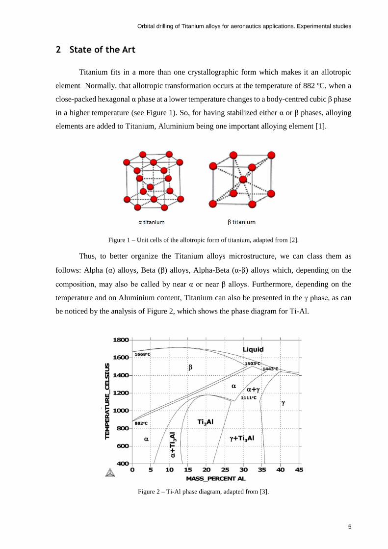
Titanium fits in a more than one crystallographic form which makes it an allotropic
element. Normally, that allotropic transformation occurs at the temperature of 882 ºC, when a
close-packed hexagonal α phase at a lower temperature changes to a body-centred cubic β phase
in a higher temperature (see Figure 1). So, for having stabilized either α or β phases, alloying
elements are added to Titanium, Aluminium being one important alloying element [1].
Figure 1 – Unit cells of the allotropic form of titanium, adapted from [2].
Thus, to better organize the Titanium alloys microstructure, we can class them as
follows: Alpha (α) alloys, Beta (β) alloys, Alpha-Beta (α-β) alloys which, depending on the
composition, may also be called by near α or near β alloys. Furthermore, depending on the
temperature and on Aluminium content, Titanium can also be presented in the γ phase, as can
be noticed by the analysis of Figure 2, which shows the phase diagram for Ti-Al.
Figure 2 – Ti-Al phase diagram, adapted from [3].

Orbital drilling of Titanium alloys for aeronautics applications. Experimental studies
6
2.1 Metallurgy of Titanium
2.1.1 Alpha (α) alloys
This corresponds to pure Titanium and Titanium alloyed with α stabilizers as for
example the Ti5Al2.5Sn. Elements as Aluminium (Al), Oxygen (O), Nitrogen (N) and Carbon
(C) are the ones denominating as α stabilizers and are responsible for the transformation
temperature raise. Aluminium is an element that gives the strength either at elevated (up to 550
ºC) or ambient temperatures and its low density takes an important advantage. Among these,
the element that most affects the mechanical properties of Titanium is the Oxygen. That comes
out from its high chemical reactivity with Titanium and its high solubility in this phase.
Although higher contents of this element increase the strength of the material, it also decreases
the machinability. Besides that, in some cases it is considered an impurity in commercial alloys
as well as N and C. Figure 3 shows how Ti-6Al-4V can change tensile properties from 900 to
950 MPa when varying the Oxygen content from 0,12 to 0,18 % in weight [4].
Figure 3- Mechanical properties of Ti-6Al-4V as a function of Oxygen content [4].
Tin (Sn) and Zirconium (Zr) are considered neutral elements. They have the capability of
strengthening the α phase, however, they have a short contribution on the transformation
temperature because they show a large solubility within α and β-phases [1].
Alpha alloys have good weldability and are non-heat treatable. The particularities of
these alloys are the low to medium tensile strength, good notch toughness and excellent
mechanical properties at cryogenic temperatures [5].

Orbital drilling of Titanium alloys for aeronautics applications. Experimental studies
7
2.1.2 Betta (β) alloys
Betta alloys are capable of producing a decrement in the transformation temperature.
There are two types within these β-stabilizers which are β-isomorphs and β-eutectoid.
Molybdenum (Mo), Vanadium (V) and Niobium (Nb) take part in the most important β-
isomorphs alloying additions. Their solubility in β-phase can decrease the β to α phase reaching
the ambient temperature. Therefore, the most important alloying additions in β-eutectoid are
Copper (Cu) and Silicon (Si). These two have restricted solubility in β-Titanium and, by
eutectoid decomposition of the β-phase, create intermetallic compounds [1].
On the application point of view, beta alloys are usually heat-treatable and have good
weldability. It has excellent formability and high strengths finding good applications on heavy
sections, sheet, fasteners and springs. Although, these alloys are not applicable for cryogenic
applications because of its tendency to ductile-brittle transition.
Some examples of these commercial alloys are: Ti15V3Cr3Al3Sn, Ti5553 and
Ti11.5Mo6Zr4.5Sn [5].
2.1.3 Alpha-Beta (α-β) alloys
As the name suggests, these alloys are composed by α and β stabilizers. These alloys
have high strength at room-temperature, moderate strength at elevated temperatures and allow
an easy formability. Also, the properties of this group can be modified with a heat treatment.
The most common and popular alloy within this group is the Ti-6Al-4V because of its
extensive use at the aerospace industry [5]. It is estimated that this alloy represents 60% of
Titanium alloys used by industry [6].
2.2 Titanium and its machinability
Titanium and its alloys have been a target of research, especially for aerospace industry
purposes. However, this material has been used in many other industries, such as automotive,
chemical, energy, medical and sporting goods (see Table 1). Machining is a very important
issue being often the most cost effective process with precision when a small volume production
is required [7].
Some reasons that make Titanium and its alloys so interesting are the high strength-to-
weight ratio, resistance to corrosion, fracture resistant characteristics and fatigue properties
maintained at elevated temperatures [1]. At marine and acid rain environments, Titanium shows
Orbital drilling of Titanium alloys for aeronautics applications. Experimental studies
8
better resistance to corrosion than any other material. Moreover, it is free from stress corrosion
cracking being very interesting as a building material.
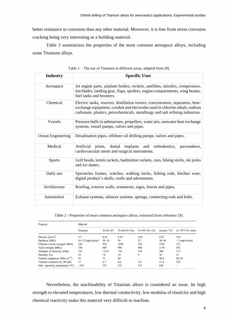
Table 2 summarizes the properties of the most common aerospace alloys, including
some Titanium alloys.
Table 1 – The use of Titanium in different areas, adapted from [8].
Industry Specific Uses
Aerospace Jet engine parts, airplane bodies, rockets, satellites, missiles, compressors,
fan blades, landing gear, flaps, spoilers, engine compartments, wing beams,
fuel tanks and boosters.
Chemical Electric tanks, reactors, distillation towers, concentrators, separators, heat-
exchange equipment, conduit and electrodes used in chlorine-alkali, sodium
carbonate, plastics, petrochemicals, metallurgy and salt refining industries.
Vessels Pressure hulls in submarines, propellers, water jets, seawater heat exchange
systems, vessel pumps, valves and pipes.
Ocean Engineering Desalination pipes, offshore oil drilling pumps, valves and pipes.
Medical Artificial joints, dental implants and orthodontics, pacemakers,
cardiovascular stents and surgical instruments.
Sports Golf heads, tennis rackets, badminton rackets, cues, hiking sticks, ski poles
and ice skates.
Daily use Spectacles frames, watches, walking sticks, fishing rods, kitchen ware,
digital product’s shells, crafts and adornments.
Architecture Roofing, exterior walls, ornaments, signs, fences and pipes.
Automotive Exhaust systems, silencer systems, springs, connecting rods and bolts.
Table 2 - Properties of most common aerospace alloys, extracted from reference [9].
Nevertheless, the machinability of Titanium alloys is considered an issue. Its high
strength to elevated temperatures, low thermal conductivity, low modulus of elasticity and high
chemical reactivity make this material very difficult to machine.

Orbital drilling of Titanium alloys for aeronautics applications. Experimental studies
9
When machining Titanium alloys, the cutting forces recorded are similar to those
generated during the machining of steels. The power consumption is generally the same or
lower [1]. However, Titanium generates very thin chips (1/3 to 1/2 for a reference steel turning
operation) making the contact area with the tool very small. Thus, these fast-flowing chips in a
combination with low thermal conductivity of the workpiece results in very high cutting
temperatures that act close to the cutting edge of the tool. As a consequence, the cutting speeds
while machining Titanium must be small in order to control the tool life at acceptable levels.
Ezugwu and Wang [1] concluded that about 80% of the heat generated in machining of Ti-6Al-
4V is pointed to the tool, while in the CK45 steel (whose current designation is C45E) that
percentage is around 50% (see Figure 4).
Figure 4 – Differences of heat distribution when machining steel and Titanium [1].
The high chemical reactivity of Titanium is a large problem for the cutting tools. When
the cutting temperatures exceed 500 ºC, Titanium reacts with almost every tool material [1].
This aspect justifies the selection of the cutting tool as a critical step in Titanium machining.
Moreover, the critical cutting speed for the beginning of shear instability and chip distribution
is considered very low. Thus, chip segmentation engages localized shearing which leads to a
generation of cyclic forces and acoustic emission [10].
Most of the stock materials for the manufacturing of aerospace components are coming
from casting. The cooling process of casting generates residual stresses at the components
because of the temperature gradient. Therefore, as the material is removed by the machining
process, there can be noticed a distortion in the machined parts due to these residual stresses
[10].

Orbital drilling of Titanium alloys for aeronautics applications. Experimental studies
10
Titanium’s low modulus of elasticity makes it easy to suffer problems due to chatter. It
deflects approximately twice comparing with carbon steel when a cutting pressure is applied,
and, due to the great spring-back behind the cutting edge, it leads to premature flank wear,
higher cutting temperatures and vibration. Thus, there is a bouncing action in the moment the
cutting tool enters the cut. Therefore, the high dynamic cutting forces, which may be up to 30
% of the static force values, may partially be responsible for the chatter. That is explained
because the titanium’s chip are formed in an adiabatic or catastrophic shear process [1].
According to Ezugwu and Wang [1], straight Tungsten Carbide (WC/Co) cutting tools
maintain their superiority in almost every machining processes of Titanium alloys.
Finally, the problems mentioned above can be minimized by using proper cutting tools,
choosing the best cutting parameters, designing special tools, using non-conventional cutting
methods, proper lubricants and very rigid machines.
2.2.1 Material groups of the workpiece
In the metal cutting industry, an extremely wide variety of metal components are
produced from many different materials. Thus, the alloying elements, heat treatment, hardness,
etc. influence each material which have their own characteristics. Therefore, in terms of
material’s organization in the metal cutting business, the ISO-standard can be followed.
According to ISO, the workpiece materials are divided into six major groups and each
group has its unique properties, concerning the machinability. Therefore, in the identification
of each group, there is the material type designation, its letter and the associated colour to each
group (see Figure 5).
Figure 5 – Workpiece material groups according in accordance with ISO standard [11].
Orbital drilling of Titanium alloys for aeronautics applications. Experimental studies
11
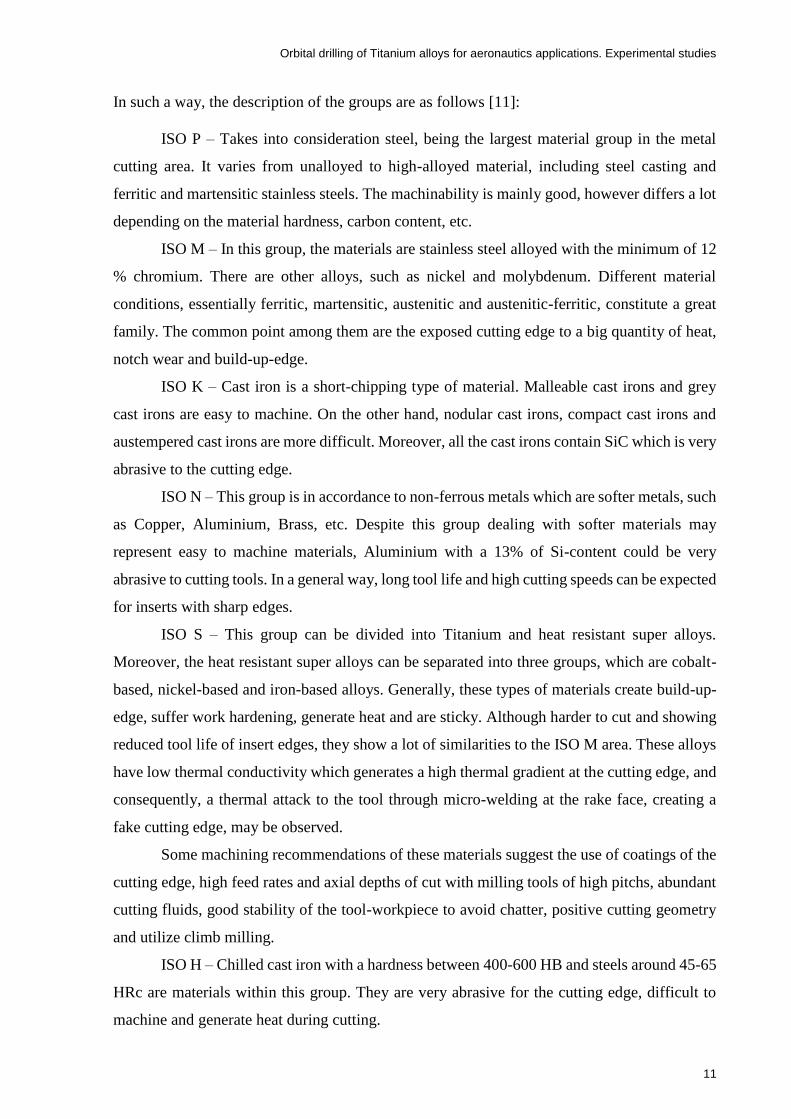
In such a way, the description of the groups are as follows [11]:
ISO P – Takes into consideration steel, being the largest material group in the metal
cutting area. It varies from unalloyed to high-alloyed material, including steel casting and
ferritic and martensitic stainless steels. The machinability is mainly good, however differs a lot
depending on the material hardness, carbon content, etc.
ISO M – In this group, the materials are stainless steel alloyed with the minimum of 12
% chromium. There are other alloys, such as nickel and molybdenum. Different material
conditions, essentially ferritic, martensitic, austenitic and austenitic-ferritic, constitute a great
family. The common point among them are the exposed cutting edge to a big quantity of heat,
notch wear and build-up-edge.
ISO K – Cast iron is a short-chipping type of material. Malleable cast irons and grey
cast irons are easy to machine. On the other hand, nodular cast irons, compact cast irons and
austempered cast irons are more difficult. Moreover, all the cast irons contain SiC which is very
abrasive to the cutting edge.
ISO N – This group is in accordance to non-ferrous metals which are softer metals, such
as Copper, Aluminium, Brass, etc. Despite this group dealing with softer materials may
represent easy to machine materials, Aluminium with a 13% of Si-content could be very
abrasive to cutting tools. In a general way, long tool life and high cutting speeds can be expected
for inserts with sharp edges.
ISO S – This group can be divided into Titanium and heat resistant super alloys.
Moreover, the heat resistant super alloys can be separated into three groups, which are cobalt-
based, nickel-based and iron-based alloys. Generally, these types of materials create build-up-
edge, suffer work hardening, generate heat and are sticky. Although harder to cut and showing
reduced tool life of insert edges, they show a lot of similarities to the ISO M area. These alloys
have low thermal conductivity which generates a high thermal gradient at the cutting edge, and
consequently, a thermal attack to the tool through micro-welding at the rake face, creating a
fake cutting edge, may be observed.
Some machining recommendations of these materials suggest the use of coatings of the
cutting edge, high feed rates and axial depths of cut with milling tools of high pitchs, abundant
cutting fluids, good stability of the tool-workpiece to avoid chatter, positive cutting geometry
and utilize climb milling.
ISO H – Chilled cast iron with a hardness between 400-600 HB and steels around 45-65
HRc are materials within this group. They are very abrasive for the cutting edge, difficult to
machine and generate heat during cutting.

Orbital drilling of Titanium alloys for aeronautics applications. Experimental studies
12
2.2.2 Cutting Tools Materials
The cutting tools while machining Titanium should have a proper hot hardness in order
to resist the elevated temperatures created at high speed conditions. Most of the tools subjected
to these conditions generally lose their hardness, decreasing the strength of the inter-particle
bond resulting in an accelerated tool wear [12]. Figure 6 shows the variation of the hardness of
common tool materials with the increase of the temperature.
Figure 6 – Tool material hardness variation with the temperature [13].
Besides the proper hot hardness, there are other requirements the tool must fulfil for the
best machining performance, which can be summarized as follows [1, 14]:
- Good thermal conductivity to reduce thermal gradients and avoid thermal shock;
- Good chemical inertness to prevent the tendency of reaction with Titanium;
- Toughness and fatigue resistance to resist the chip segmentation;
- High tensile, compressive and shear strength;
- Low cobalt content;
- Have a positive/open geometry with good edge toughness.
The use of coated carbide tools, CBN/PCBN tools and ceramics is recommended for high
speed machining conditions while uncoated carbide tools are used at low speed machining

Orbital drilling of Titanium alloys for aeronautics applications. Experimental studies
13
conditions. The high chemical reactivity of Titanium alloys with the ceramic tools makes these
materials usually not used. Even though this kind of materials are used to machine difficult-to-
cut materials at high temperature such as nickel-based alloys, most of ceramics have also poor
thermal conductivity and relatively low fracture toughness [12] [1].
The machining of Titanium alloys with high cutting speeds over 45 m/min usually use
uncoated straight grade cemented carbide/straight tungsten carbide (WC-Co) tools. Ezugwu
and Wang [1] defend that these types of tools are superior in almost every titanium machining
processes at interrupted cutting (tapping, broaching, planning and end milling). The high-speed
machining leads to high cutting temperature close to the tool nose, inducing excessive stresses
originating plastic deformation and a posterior tool failure. With temperatures over 500 ºC,
Titanium atoms diffuse into the carbide tool material, chemically reacting with the carbon of
the tool, generating an interlayer of Titanium carbide (TiC).
In interrupted cutting, drilling, reaming and tapping, high speed steels are recommended.
On the other hand, the recommendation for continuous cutting, slab and face milling are carbide
tools [7].
Cubic boron nitride (CBN) and polycrystalline diamond (PCD) have shown a great
performance in relation to wear rate, although their application is limited due to their high prices
[1]. With the use of CBN, the cutting forces generated are lower in comparison with other tool
materials because this type of tools maintain their hardness below critical temperatures while
Titanium softens. However, in the Titanium phase transformation at the temperature around
800-850 ºC (see Section 2), the wear rate of this kind of tools are significantly affected.
Moreover, in PCD and CBN, the critical temperature so that adhesion can occur is 760 and 900
ºC, respectively [12].
2.2.3 Tool coatings
The ideal mechanical properties of the cutting tools should include elevated hardness
along with toughness. However, when the hardness increases, the toughness decreases and vice
versa. According to this, coating gives great hardness surface, maintaining the toughness of the
substrate. Thus, the main coatings for the machining of Titanium are manufactured based on
oxides, nitrides and carbides in multilayers, as can be read as follows [15]:
Al2O3 - Aluminium oxide;
TiAlN - Aluminium titanium nitride;
TiC - Titanium carbide;
TiN - Titanium nitride;
Orbital drilling of Titanium alloys for aeronautics applications. Experimental studies
14
TiCN – Titanium carbonitride.
The Aluminium oxide and Titanium carbide are very hard materials and have good
chemical stability and wear resistance. On the other hand, Titanium nitride is not that hard
material, but has a low friction coefficient, decreasing the tendency for crater and fake cutting
edge formation. In addition, the nitrides can be applied at lower temperatures, not affecting the
substrate.
Titanium carbonitride has excellent adhesion properties under upper and underneath the
substrate. Aluminium Titanium nitride also has good adhesion properties, however it needs a
heat barrier to perform the combination with Aluminium oxide, avoiding overheating.
2.3 Milling
Milling is a conventional manufacturing/machining process. It has been in constant
evolution along the time because, besides all the conventional applications, this type of
machining shows interesting characteristics in drilling, opening cavities, threading and turning
[16]. In terms of definition, milling consists in cutting material with a rotary tool of multiple
edges, making programmed movements on the workpiece in almost every direction. It is this
cutting action that turns this process so efficient and versatile. Each cutting edge removes a
certain quantity of material, using a limited cutting action which makes the chip formation and
exit a secondary issue. Even though, mostly of the cases, milling is still used for the machining
of plane surfaces [16].
2.3.1 Types of milling
In a milling operation, the tool performs one or a group of basic cutting operations which
are radial, periphery and axial. Therefore, the types of milling operations that can be performed
can be summarized as follows [17]:
Shoulder milling
Face milling
Profile milling
Turn milling
Slot milling
Holes and cavities
Chamfering
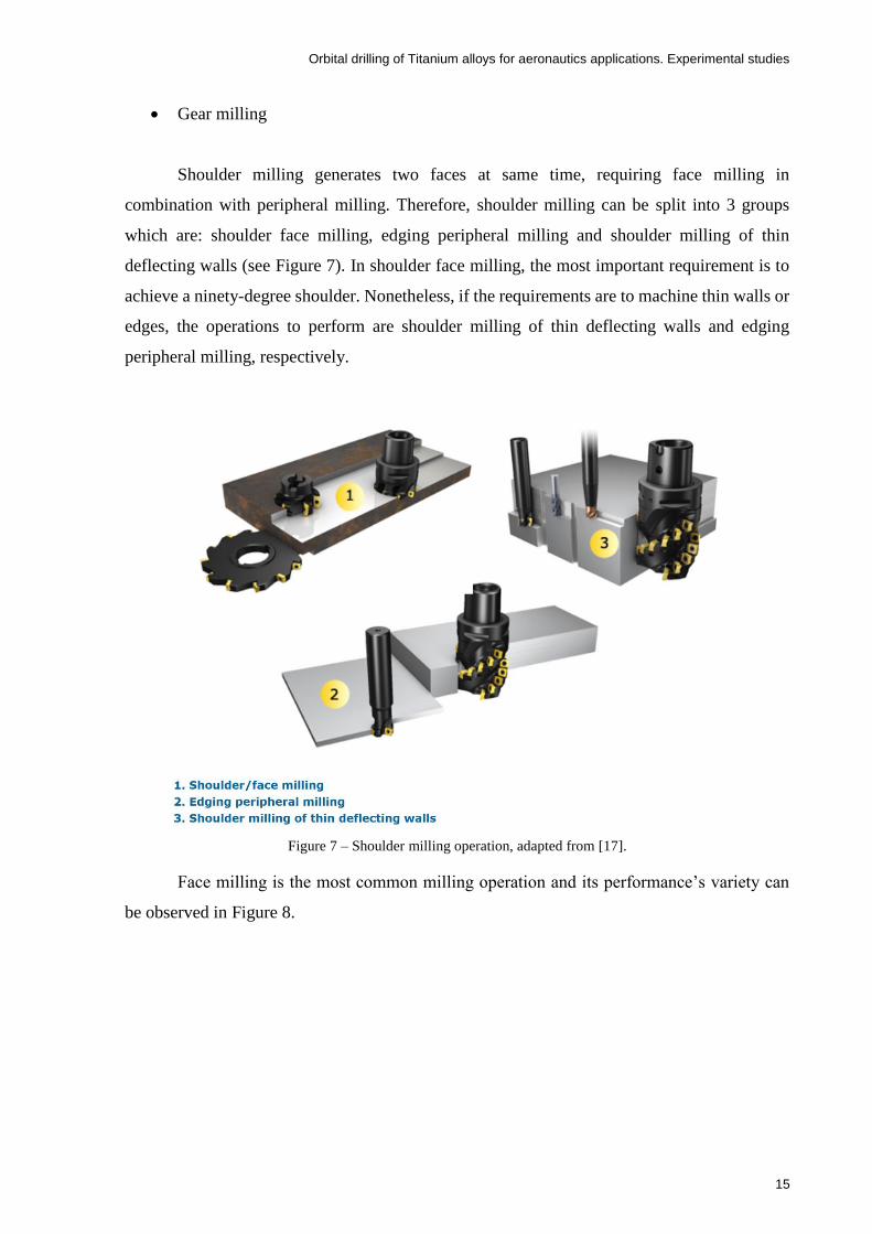
Orbital drilling of Titanium alloys for aeronautics applications. Experimental studies
15
Gear milling
Shoulder milling generates two faces at same time, requiring face milling in
combination with peripheral milling. Therefore, shoulder milling can be split into 3 groups
which are: shoulder face milling, edging peripheral milling and shoulder milling of thin
deflecting walls (see Figure 7). In shoulder face milling, the most important requirement is to
achieve a ninety-degree shoulder. Nonetheless, if the requirements are to machine thin walls or
edges, the operations to perform are shoulder milling of thin deflecting walls and edging
peripheral milling, respectively.
Figure 7 – Shoulder milling operation, adapted from [17].
Face milling is the most common milling operation and its performance’s variety can
be observed in Figure 8.

Orbital drilling of Titanium alloys for aeronautics applications. Experimental studies
16
Figure 8 – Face milling, adapted from [17].
When the milling of more complex profiles is a requisite, the recommendation is to use
profile milling that covers multi-axis milling of a concave and convex shapes into two and three
dimensions.
When conventional turning or milling methods cannot produce some eccentric shapes
or forms, turn milling usually can. Moreover, this method is capable of a superb chip control
for high metal removal. Thus, turn milling is defined as the milling of a curved surface while
the workpiece is rotating around its centre point.
Other frequent milling operations are the production of chamfers, undercuts, V-cuts,
deburring and preparation for welding operations. According to this, those operations are named
by chamfering and can be performed using a long edge cutter, a small face mill, an end mill or
even dedicated chamfering cutters.
Gear milling is a new technology in which Sandvik claims that will transform the gear
manufacturing business. Moreover, they have proved that with this technology, they can
increase the productivity in a range of 200 to 500 % in the manufacturing of these components.
An illustration about profile milling, turn milling, gear milling, slot milling and chamfering can
be observed in Figure 9.

Orbital drilling of Titanium alloys for aeronautics applications. Experimental studies
17
Figure 9 – Illustration of profile milling, turn milling, gear milling, slot milling and chamfering, adapted from
[17].
Finally, milling operation is also capable of producing holes and cavities in some kinds
of forms and profiles, as can be seen in Figure 10. However, this thesis will only focus on
circular ramping milling (Number 2 of Figure 10), which is known as helical milling or orbital
drilling, depending on the literature sources.

Orbital drilling of Titanium alloys for aeronautics applications. Experimental studies
18
Figure 10- Milling operation in order to produce holes and cavities, adapted from [17].
2.3.2 Basic definitions in milling process
In milling manufacturing process as well as in every machining process, there are some
basic definitions to be known so that all the procedures are well understood (see Table 3) [16].

Orbital drilling of Titanium alloys for aeronautics applications. Experimental studies
19
Table 3 – Basic definitions in the milling process
Symbol Name Unity Definition
vc Cutting velocity m/min Velocity in which the cutting edge works on the
workpiece. This is a specific value of the tool.
n Spindle frequency rpm Number of rotations the tool performs in each
minute. It is calculated based on the cutting speed
recommended in every operation.
vf Feed rate mm/min Cutter’s relative velocity in advance along the
workpiece.
hex Maximum chip
thickness
mm It is the most important indicator in terms of
limitation of the tool to a certain operation. The
cutting edges of the tool are developed and tested
with an initial recommended value.
st Feed rate per tooth mm/tooth Linear distance travelled by the tool while a certain
tooth is in the cutting process. This value can be
calculated based on the maximum chip thickness
recommended.
fn Feed rate per
rotation
mm/rot It is a value specially used for the feed rate’s
calculation, and, generally determines the capacity of
finishing of the tool.
ap Axial depth of cut mm Dimension of material the tool can remove from the
workpiece.
ae Radial length of cut mm Length of the workpiece that is not under the tool
diameter action.
Q Material’s removal
rate
mm3 Volume of material removed in a certain period.
Tc Machining time min It is the action period of the tool.
Pc Power kW Consumed power of the machine-tool.
kr Positioning angle Degrees Main angle of the cutting edge of the tool and it is
one important factor in the direction of the cutting
force and chip thickness.
2.3.3 Milling direction
When the rotation of the milling tool in the cutting area has the same direction of the
milling tool feed´s rate, this milling operation is named as climb milling/down milling. In this
case, the chip thickness decreases since the beginning of the cut until gets zero millimetres in
peripheral milling operations (see Figure 11). Generally, the machining insert starts cutting
generating chips of great thickness, decreasing the plastic strain hardening of the workpiece and
the cutting forces tend to push the workpiece against the milling tool, keeping the machining
inserts in the cut [16].
On the other hand, when the milling rotation at the cutting area has an opposite direction
comparatively to its feed rate, that process is named by conventional milling/up milling. In this

Orbital drilling of Titanium alloys for aeronautics applications. Experimental studies
20
case, the milling tool initiates the cut with an approximately zero chip thickness and increases
until the end of the cut. Therefore, there are big cutting forces which tend to deviate the
workpiece from the tool [16].
The insert upon penetration creates a friction at high temperatures, generally meeting a
hardened surface caused by the anterior insert by plastic deformation.
In the milling process, the chip stay attached to the cutting edge until the next cut. When
this situation happens, at conventional milling, the chip can stay attached between the cutting
tool and the workpiece which can, sometimes, damage the tool. On the other hand, at climb
milling the chip would break into two pieces and would not damage the tool. Besides, with this
type of milling, the chips produced stay behind the cutting tool increasing significantly the tool
life and giving better surface finish. Another advantage of climb milling is the possibility of
using a higher rake angle which decreases the power consumption [18].
Thus, when the workpiece and the cutting tool allow, it is desirable to approach the cut
with climb milling.
Figure 11 – Scheme of conventional milling and climb milling, adapted from [18]
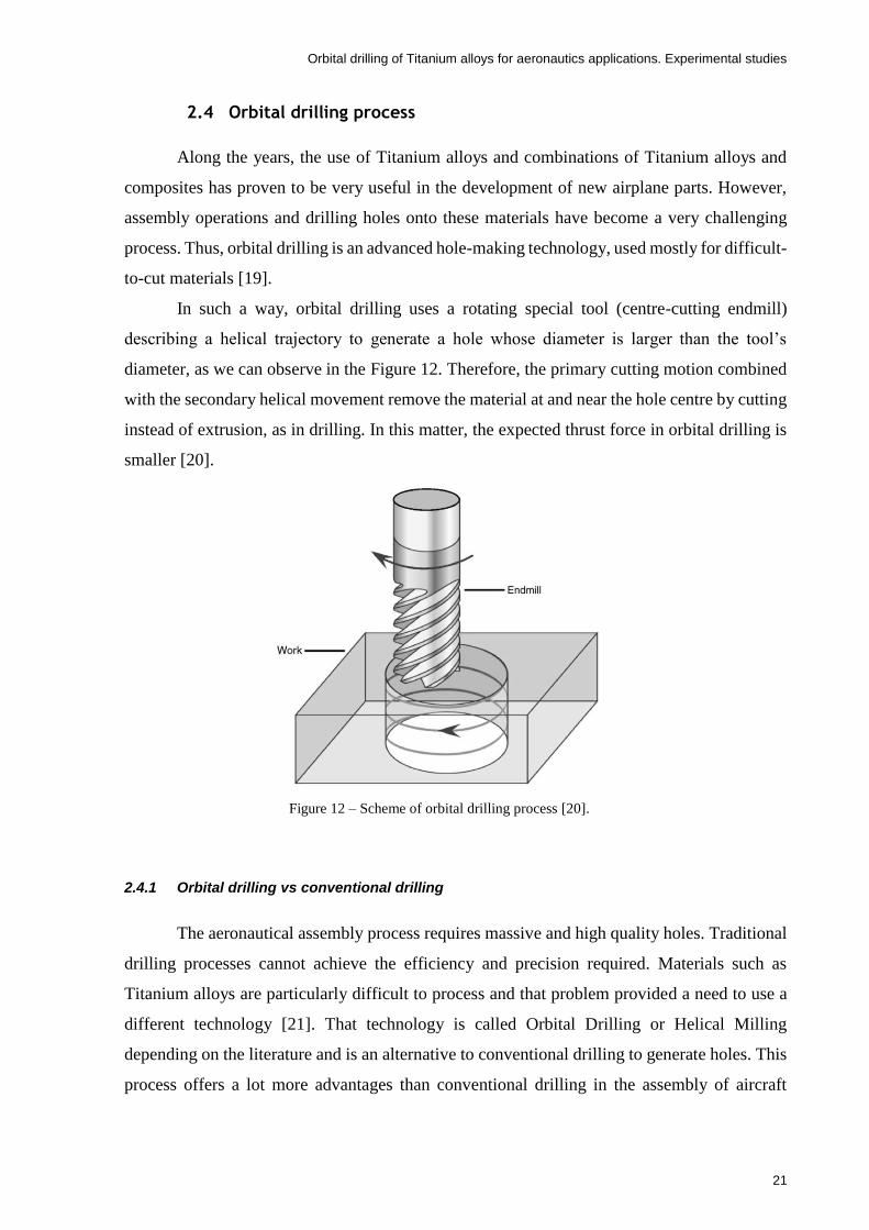
Orbital drilling of Titanium alloys for aeronautics applications. Experimental studies
21
2.4 Orbital drilling process
Along the years, the use of Titanium alloys and combinations of Titanium alloys and
composites has proven to be very useful in the development of new airplane parts. However,
assembly operations and drilling holes onto these materials have become a very challenging
process. Thus, orbital drilling is an advanced hole-making technology, used mostly for difficult-
to-cut materials [19].
In such a way, orbital drilling uses a rotating special tool (centre-cutting endmill)
describing a helical trajectory to generate a hole whose diameter is larger than the tool’s
diameter, as we can observe in the Figure 12. Therefore, the primary cutting motion combined
with the secondary helical movement remove the material at and near the hole centre by cutting
instead of extrusion, as in drilling. In this matter, the expected thrust force in orbital drilling is
smaller [20].
Figure 12 – Scheme of orbital drilling process [20].
2.4.1 Orbital drilling vs conventional drilling
The aeronautical assembly process requires massive and high quality holes. Traditional
drilling processes cannot achieve the efficiency and precision required. Materials such as
Titanium alloys are particularly difficult to process and that problem provided a need to use a
different technology [21]. That technology is called Orbital Drilling or Helical Milling
depending on the literature and is an alternative to conventional drilling to generate holes. This
process offers a lot more advantages than conventional drilling in the assembly of aircraft

Orbital drilling of Titanium alloys for aeronautics applications. Experimental studies
22
structures. These advantages become highly more relevant with the materials being used
nowadays. These advantages can be summarized as [22, 23]:
Excellent chip evacuation and heat dissipation because the hole diameter is
larger than the tool’s diameter;
Better tool life and more efficient cooling because of the intermittent cutting;
Possibility of dry cutting;
Lower thrust cutting force due to its process kinematics (see Figure 13);
Very cost-effective hole making process because different holes can be
generated in the workpiece, using only one tool diameter;
Delamination-free drilling in laminated composite materials due to the lower
thrust forces.
However, conventional drilling also offers some advantages upon orbital drilling. The
tool design is simpler as well as the process kinematics, giving the possibility of making smaller
holes than in orbital drilling. The process time is lower increasing the productivity (see Figure
13), being an industry relevant factor. Moreover, it is a more ancient process which brings up a
lot more information from literature.
Figure 13 – Machining time and thrust force in : (a) conventional drilling, and (b) orbital drilling, extracted from
[20].
Qin, et al. [21] made a comparative study on orbital drilling and conventional drilling
of Ti-6Al-4V, focusing on the analysis of the cutting forces, tool wear and the quality of holes.
In orbital drilling, the cutting forces were about 1/5 when compared with conventional milling,
the tool wear improved and obtained nearly zero burr formation. In conventional drilling, it was
only possible to make a few holes, while in helical milling they were able to produce about 140
holes. Also, the diameter deviation was much lower in orbital drilling. In Figure 14 one can
observe the difference between the chip geometry of traditional drilling and orbital drilling. In
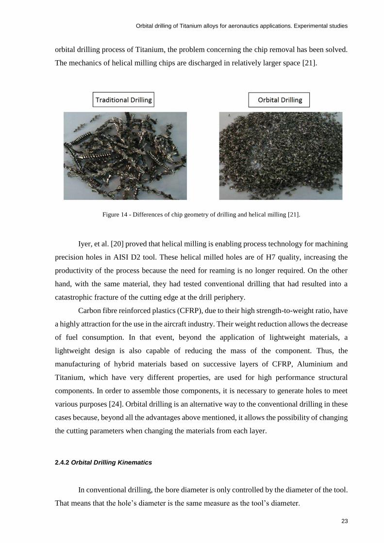
Orbital drilling of Titanium alloys for aeronautics applications. Experimental studies
23
orbital drilling process of Titanium, the problem concerning the chip removal has been solved.
The mechanics of helical milling chips are discharged in relatively larger space [21].
Figure 14 - Differences of chip geometry of drilling and helical milling [21].
Iyer, et al. [20] proved that helical milling is enabling process technology for machining
precision holes in AISI D2 tool. These helical milled holes are of H7 quality, increasing the
productivity of the process because the need for reaming is no longer required. On the other
hand, with the same material, they had tested conventional drilling that had resulted into a
catastrophic fracture of the cutting edge at the drill periphery.
Carbon fibre reinforced plastics (CFRP), due to their high strength-to-weight ratio, have
a highly attraction for the use in the aircraft industry. Their weight reduction allows the decrease
of fuel consumption. In that event, beyond the application of lightweight materials, a
lightweight design is also capable of reducing the mass of the component. Thus, the
manufacturing of hybrid materials based on successive layers of CFRP, Aluminium and
Titanium, which have very different properties, are used for high performance structural
components. In order to assemble those components, it is necessary to generate holes to meet
various purposes [24]. Orbital drilling is an alternative way to the conventional drilling in these
cases because, beyond all the advantages above mentioned, it allows the possibility of changing
the cutting parameters when changing the materials from each layer.
2.4.2 Orbital Drilling Kinematics
In conventional drilling, the bore diameter is only controlled by the diameter of the tool.
That means that the hole’s diameter is the same measure as the tool’s diameter.

Orbital drilling of Titanium alloys for aeronautics applications. Experimental studies
24
In orbital drilling, the bore diameter is obtained combining the diameter of the tool with
the helical path. Under this circumstances, it is important to know the orbital drilling
kinematics. In that order, depending on the material, on the surface finish and on the velocity
of the process which takes a primordial part on the production, there are several parameters to
be controlled. The main of those are the spindle speed n (rot/min), the feed rate per tooth st
(mm/tooth) and the axial feed per orbital revolution a (mm/rot), as shown in Figure 15 [22]. In
the
Table 4, all the variables of the process are designated.
Figure 15 – Scheme of helical milling process, [22]
Table 4 – Variables used in the orbital drilling process
Symbol Description Units
Dt Tool Diameter mm
Dh Hole Diameter mm
vc Cutting speed m/min
st feed rate/tooth tangential mm/tooth
fa feed rate/tooth axial mm/tooth
n Spindle rotation speed rpm
np Revolutionary speed rpm
vfz Feed velocity mm/min
a Axial feed per orbital revolution mm/rot
vfa Axial feed velocity mm/min
Z Number of teeth
α Ramp angle degrees

Orbital drilling of Titanium alloys for aeronautics applications. Experimental studies
25
Under the circumstances, the Figure 16, exhibits the tool offset and the trajectory of the
tool centre in one orbital revolution.
Figure 16 – Tool offset and trajectory of the tool centre in one orbital revolution, adapted from [22]
Thus, ramp angle value is given by
𝛼 = 𝑡𝑎𝑛−1(𝑎
𝜋(𝐷ℎ − 𝐷𝑡))
(1)
And the axial feed per orbital revolution is calculated as
𝑎 = 𝑣𝑓𝑎
𝑛𝑝
(2)
When the axial feed velocity is given by
𝑣𝑓𝑎 = 𝑛 𝑍 𝑓𝑎 (3)
In the milling process, the cutting speed velocity is expressed by
𝑣𝑐 =
𝜋 𝐷𝑡 𝑛
1000
(4)
And the feed velocity is
𝑣𝑓𝑧 = 𝑛 𝑍 𝑠𝑡 (5)

Orbital drilling of Titanium alloys for aeronautics applications. Experimental studies
26
Therefore, the revolutionary speed is given dividing the feed velocity per the perimeter
of the tool offset, as follows
𝑛𝑝 =
𝑠𝑡 𝑍 𝑛
𝜋 (𝐷ℎ − 𝐷𝑐)
(6)
2.4.3 Chip formation
In any metal cutting process, the chip formation is a mandatory issue. The tool induces
severe shearing stresses on the workpiece material originating the material above the cutting
edge to yield and flow plastically in a form of a chip. Thus, when the material’s ultimate stress
is exceeded, the separation of the chip occurs. In this way, there are four main basic chip
geometry types that may occur in all metal cutting processes, which are [25, 26]:
Continuous;
Lamellar;
Segmented;
Discontinuous.
Continuous chip formation
In continuous chip formation, the chip flows off the rake face at a constant speed in a
stationary way. The machining of ductile materials under certain conditions such as high cutting
speeds, low feed rate and low friction between the tool and the chip is responsible for the
appearance of these types of chips. Additionally, the use of a tool with high positive rake angle
and sharp cutting edge, also have a contribution to the formation of this type of chip [26].
This type of chips can have a negative contribution at the surface finish of the machined
workpiece. High temperatures and pressure conditions when put together with a high friction
in the tool-chip interface origin build up edges (BUE) that tend to grow along the machining
process. BUE appear when the workpiece material adheres to the tool cutting edge, having a
negative effect in the chip formation [26].
Lamellar chip formation
When the chips are in a form of cyclical shaped continuous chips, they are named by
lamellar chip type. Relevant cleavages can be found due to the variations in the deformation
process [26]. Moreover, this chip type has frequently wavy shapes. Figure 17 illustrates the
differences between a continuous chip shape and a lamellar chip shape.
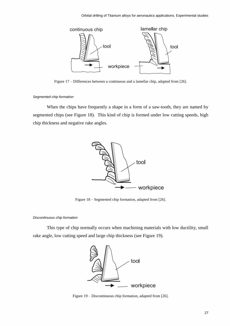
Orbital drilling of Titanium alloys for aeronautics applications. Experimental studies
27
Figure 17 – Differences between a continuous and a lamellar chip, adapted from [26].
Segmented chip formation
When the chips have frequently a shape in a form of a saw-tooth, they are named by
segmented chips (see Figure 18). This kind of chip is formed under low cutting speeds, high
chip thickness and negative rake angles.
Figure 18 – Segmented chip formation, adapted from [26].
Discontinuous chip formation
This type of chip normally occurs when machining materials with low ductility, small
rake angle, low cutting speed and large chip thickness (see Figure 19).
Figure 19 – Discontinuous chip formation, adapted from [26].

Orbital drilling of Titanium alloys for aeronautics applications. Experimental studies
28
Denkena, et al. [27] studied the chip formation in orbital drilling of CFRP-Titanium
layer compounds. They concluded that there are two chip formations in orbital drilling process.
One chip formation comes out from the continuous cut performed by the axial cutting edge,
resulting in small segmented chips. The other chip formation is due to the discontinuous cut
generated from the radial cutting edges, originating very small discontinuous chips (see Figure
20). However, in this process the chip size is very small, facilitating the chip extraction, solving
the problem of chip evacuation (see Figure 14).
Figure 20 – Chip formation in orbital drilling process of Ti-6Al-4V, adapted from [27].
2.4.4 Lubrication
The main roles of the lubricant fluid are to reduce the friction between the tool and the
workpiece and reduce the temperature in the cutting process. In that order, an adequate coolant
delivery is required, as it is shown in Figure 21. When applied with the correct pressure and
direction, the fluid helps the chip removal and gives an anti-corrosive effect between the tool
and the workpiece [5].
Figure 21 – Cooling delivery [5].

Orbital drilling of Titanium alloys for aeronautics applications. Experimental studies
29
The high temperatures on the cutting zone cause chips that can easily weld to the tool
leading to a premature tool failure. Moreover, this cutting zone spoils the surface integrity of
the holes by inducing tensile residual stresses. For that reason, during machining, a cutting fluid
directed to the sliding surface is usually utilized. Also, the application of a large amount of
cutting fluid in intermittent cutting must be avoided because it may cause a thermal shock,
initiating thermal cracks on the cutting edge which may lead to a consequent tool failure due to
edge fracture [28].
A great amount of research workers defend that the costs related to cutting fluids are
usually higher than those related to cutting tools [29]. Thus, a solution to this, besides dry
machining, is the minimum quantity lubrication (MQL). This cooling process uses a mix of a
very small quantity of oil with a copious amount of high pressure air. This technique has been
adopted and some good results were obtained in Titanium alloys machining.
Su, et al. [30] experimented high speed end milling of Ti-6Al-4V with the cutting speed
of 400 m/min under several lubrication and cooling conditions. Their results showed that
compressed cold nitrogen gas increase the tool life when compared with flood coolants. The
flood coolant lubricant method has proved to be unsuitable for high speed. Liao, et al. [31]
investigated the performance of MQL in high-speed end milling of NAk80 hardened steel using
a coating carbide tool. Their results showed that MQL use during the milling of die steels
produced better surface finish and had shown better performance than flood coolants. Besides,
the cutting using those coolants resulted into thermal cracks and consequently shorter tool lives.
Rahim and Sasahara [32] compared the lubricant performance of MQL palm oil (MQLPO),
MQL synthetic ester (MQLSE), flood conditions and air blow while performing high speed
drilling of Ti-6Al-4V. Their results demonstrated that MQLPO has better performance on
temperature and cutting forces comparing with MQLSE.
However, to meet the needs of aeronautical manufactures, dry machining is
recommended. Dry machining will conduct to a safer assembly environment and reduces
significantly the costs of production. Moreover, it is a great advantage while machining
composite materials so the lubricant does not damage the composite matrix. On the other hand,
on Titanium alloys, dry machining could be very challenging due to the low thermal
conductivity of the material, relatively low modulus of elasticity and high temperature strength
of this material, which leads to very high temperature increase at the cutting edge of the tool
[33].

Orbital drilling of Titanium alloys for aeronautics applications. Experimental studies
30
2.4.5 Cutting Forces
The cutting forces can be a good indicator to know if a certain material is difficult or
easy to machine. When these forces have a large increase, can originate a large vibration at the
tool axis leading to bad surface finishes. Moreover, decreases the tool life and, in some cases,
even lead to a premature failure of the tool. A larger cutting force means a larger friction
between the workpiece and the tool which leads to a bigger heat production at the
workpiece/tool interface.
Figure 22 compares different specific cutting forces for different types of metals. There
can be noticed that Titanium cutting forces are bigger than those obtained in the aluminium
alloy and cast iron, however they are smaller when comparing with steel. Also, Figure 23 shows
that the energy consumption of Titanium machining is slightly smaller when comparing with
steel and nickel-based alloys, respectively.
Figure 22 – Specific cutting forces while machining different metals [34].
Figure 23 – Power required to machine different metals [34].

Orbital drilling of Titanium alloys for aeronautics applications. Experimental studies
31
Konig [35] has reported bigger stresses on the tool while machining Ti-6Al-4V than
when machining Nimonic (nickel-based alloy) and three to four times than machining Ck53N.
These results are explained due to the unusual small contact area between the workpiece and
the rake face of the tool (about 1/3 of the contact area when machining steel at the same axial
depth of cut and feed rate) and also slightly due to the Titanium high resistance to elevated
temperatures [1].
In the orbital drilling process, the cutting forces are divided into three axis because the
path of the tool centre is different from the orbital path of the tool. So, Wang, et al. [36]
concluded that the axial cutting force is bigger than the in-plane cutting forces, being these last
two forces nearly coincident. Besides, bigger cutting forces were obtained with the increase of
the orbital speed velocity and feed rate per tooth. On the other hand, smaller cutting forces were
obtained with the increase of the spindle rotation speed. In addition, increasing the axial depth
of cut per revolution in 100%, the cutting force coefficients will decrease about 30%. This
author also developed an analytical mechanistic model for the cutting forces under steady-state
conditions, which considers the bottom and peripheral edges because both contribute to the
cutting process. However, that model still needs a further developments and discussion due to
the complexity of the cutting process.
Nevertheless, the tool wear is directly related with the cutting force values. Using the
same tool and increasing the machining hole number, the thrust force increases, while the radial
forces slightly increase (see Figure 24).
Figure 24 – Cutting force vs. number of machined holes in Ti-6Al-4V (cutting speed, 100 m/min; feed per tooth,
0.04 mm/tooth; depth of cut, 0.2 mm/rev), adapted from [33].
The reduction of machining damage can be obtained with the planning and optimization
of the machining process. Consequently, the prediction of the cutting forces is very important
because, in orbital drilling process, the bottom cutting edges and the periphery cutting edges
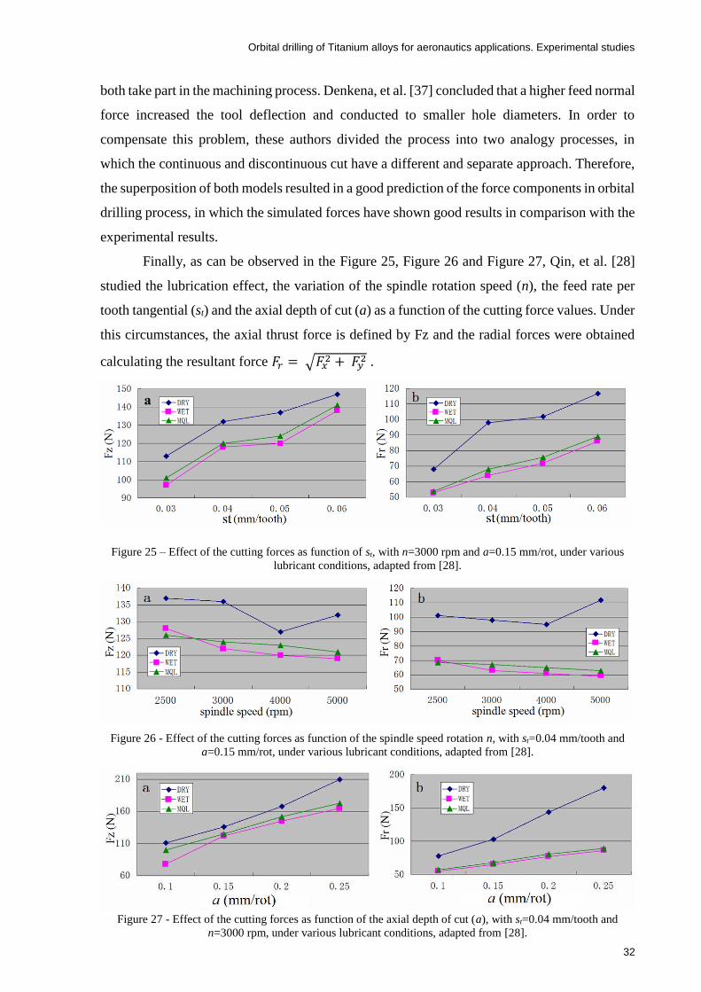
Orbital drilling of Titanium alloys for aeronautics applications. Experimental studies
32
both take part in the machining process. Denkena, et al. [37] concluded that a higher feed normal
force increased the tool deflection and conducted to smaller hole diameters. In order to
compensate this problem, these authors divided the process into two analogy processes, in
which the continuous and discontinuous cut have a different and separate approach. Therefore,
the superposition of both models resulted in a good prediction of the force components in orbital
drilling process, in which the simulated forces have shown good results in comparison with the
experimental results.
Finally, as can be observed in the Figure 25, Figure 26 and Figure 27, Qin, et al. [28]
studied the lubrication effect, the variation of the spindle rotation speed (n), the feed rate per
tooth tangential (st) and the axial depth of cut (a) as a function of the cutting force values. Under
this circumstances, the axial thrust force is defined by Fz and the radial forces were obtained
calculating the resultant force 𝐹𝑟 = √𝐹𝑥2 + 𝐹𝑦
2 .
Figure 25 – Effect of the cutting forces as function of st, with n=3000 rpm and a=0.15 mm/rot, under various
lubricant conditions, adapted from [28].
Figure 26 - Effect of the cutting forces as function of the spindle speed rotation n, with st=0.04 mm/tooth and
a=0.15 mm/rot, under various lubricant conditions, adapted from [28].
Figure 27 - Effect of the cutting forces as function of the axial depth of cut (a), with st=0.04 mm/tooth and
n=3000 rpm, under various lubricant conditions, adapted from [28].
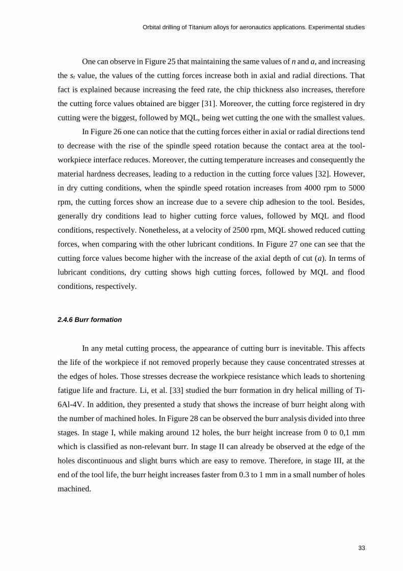
Orbital drilling of Titanium alloys for aeronautics applications. Experimental studies
33
One can observe in Figure 25 that maintaining the same values of n and a, and increasing
the st value, the values of the cutting forces increase both in axial and radial directions. That
fact is explained because increasing the feed rate, the chip thickness also increases, therefore
the cutting force values obtained are bigger [31]. Moreover, the cutting force registered in dry
cutting were the biggest, followed by MQL, being wet cutting the one with the smallest values.
In Figure 26 one can notice that the cutting forces either in axial or radial directions tend
to decrease with the rise of the spindle speed rotation because the contact area at the tool-
workpiece interface reduces. Moreover, the cutting temperature increases and consequently the
material hardness decreases, leading to a reduction in the cutting force values [32]. However,
in dry cutting conditions, when the spindle speed rotation increases from 4000 rpm to 5000
rpm, the cutting forces show an increase due to a severe chip adhesion to the tool. Besides,
generally dry conditions lead to higher cutting force values, followed by MQL and flood
conditions, respectively. Nonetheless, at a velocity of 2500 rpm, MQL showed reduced cutting
forces, when comparing with the other lubricant conditions. In Figure 27 one can see that the
cutting force values become higher with the increase of the axial depth of cut (a). In terms of
lubricant conditions, dry cutting shows high cutting forces, followed by MQL and flood
conditions, respectively.
2.4.6 Burr formation
In any metal cutting process, the appearance of cutting burr is inevitable. This affects
the life of the workpiece if not removed properly because they cause concentrated stresses at
the edges of holes. Those stresses decrease the workpiece resistance which leads to shortening
fatigue life and fracture. Li, et al. [33] studied the burr formation in dry helical milling of Ti-
6Al-4V. In addition, they presented a study that shows the increase of burr height along with
the number of machined holes. In Figure 28 can be observed the burr analysis divided into three
stages. In stage I, while making around 12 holes, the burr height increase from 0 to 0,1 mm
which is classified as non-relevant burr. In stage II can already be observed at the edge of the
holes discontinuous and slight burrs which are easy to remove. Therefore, in stage III, at the
end of the tool life, the burr height increases faster from 0.3 to 1 mm in a small number of holes
machined.

Orbital drilling of Titanium alloys for aeronautics applications. Experimental studies
34
Figure 28 – Burr height at the hole’s exit versus the number of holes machined with dry helical milling [33]
In metal cutting operations, there are three types of burrs: Rollover burr, poison burr
and breakout burr [38]. Moreover, burrs can be classified by its physical appearance of
formation. Poison burr is related to the plastic deformation of the material which includes lateral
flow. Rollover burr is related to bending while tear burr, as the name indicates, is related to the
tearing of material from the workpiece. Thus, Li, et al. [33] concluded that in orbital drilling
of Ti-6Al-4V there are two kinds of burr which are rollover burr and tear burr. With the increase
of cutting times in the stage II, a serious crater wear occurred at the tool nose. Bending and
lateral flow where originated when the consumed cutting edge cut the irregular exit’s edge of
the hole. In that effect, they concluded that in stage II, a rollover burr appears at the exit of the
hole. Furthermore, in stage III, yet with the increasing of cutting time, occurred a catastrophic
failure at the front cutting edges. That way, the cutting tool, instead of cutting, extruded the
workpiece material off, originating a large plastic deformation at the exit of the hole. Thus,
when the fracture limit of the workpiece material was reached by the thrust force applied, the
tear burr happens because tearing break happened at the boundary of the cap.
2.4.7 Tool life
About the tool contribution at helical milling process, either the front cutting edges or
the periphery cutting edges take part in the machining process simultaneously. While the
periphery cutting edge is removing the periphery material of the borehole, the front cutting edge
is removing the material at the bottom of the borehole [39].
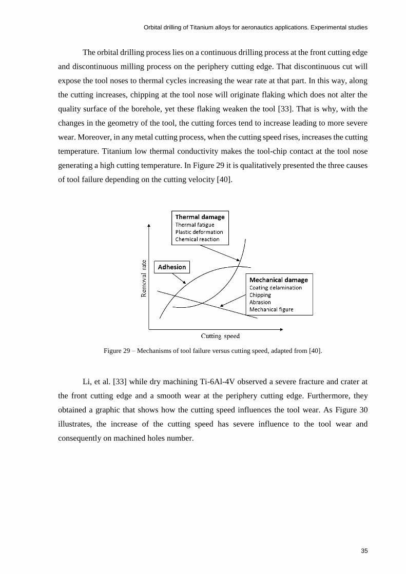
Orbital drilling of Titanium alloys for aeronautics applications. Experimental studies
35
The orbital drilling process lies on a continuous drilling process at the front cutting edge
and discontinuous milling process on the periphery cutting edge. That discontinuous cut will
expose the tool noses to thermal cycles increasing the wear rate at that part. In this way, along
the cutting increases, chipping at the tool nose will originate flaking which does not alter the
quality surface of the borehole, yet these flaking weaken the tool [33]. That is why, with the
changes in the geometry of the tool, the cutting forces tend to increase leading to more severe
wear. Moreover, in any metal cutting process, when the cutting speed rises, increases the cutting
temperature. Titanium low thermal conductivity makes the tool-chip contact at the tool nose
generating a high cutting temperature. In Figure 29 it is qualitatively presented the three causes
of tool failure depending on the cutting velocity [40].
Figure 29 – Mechanisms of tool failure versus cutting speed, adapted from [40].
Li, et al. [33] while dry machining Ti-6Al-4V observed a severe fracture and crater at
the front cutting edge and a smooth wear at the periphery cutting edge. Furthermore, they
obtained a graphic that shows how the cutting speed influences the tool wear. As Figure 30
illustrates, the increase of the cutting speed has severe influence to the tool wear and
consequently on machined holes number.

Orbital drilling of Titanium alloys for aeronautics applications. Experimental studies
36
Figure 30 – Tool wear versus cutting speed (st=0,04 mm/tooth ; a=0,2 mm/rot) [33].
Qin, et al. [28] studied the tool life in high speed helical milling of Ti-6Al-4V using a
coated carbide tool with the application of MQL palm oil, dry and flood conditions (see Figure
31). They defined their tool life as 0,2 mm of flank wear using the cutting parameters of n =
5000 rpm, a = 0,2 mm/rot and st = 0,04 mm/tooth. Their results showed that MQL has the better
performance in terms of tool life. Beyond that, it is interesting to observe three stages in the
tool life under the different lubricant conditions. A first stage where there is a fast increasing of
the tool wear due to the abrasion and micro-chipping at the sharp cutting edge is verified; then
the tool wear increases gradually until the last stage where there is the tool failure.
Figure 31 – Tool life under dry, wet and MQL conditions [28].

Orbital drilling of Titanium alloys for aeronautics applications. Experimental studies
37
Table 5 summarizes main problems related to the tool wear and describes possible
solutions.
Table 5 – Typical wear on cutting edges and possible solutions [41].
Tool Wear Problem Solution
Rapid wear producing poor
surface finish or out of
tolerance
Select a more wear-resistant
grade
Reduce the cutting speed
Increase the feed rate
Excessive wear caused by
vibration, re-cutting of chips,
burr formation on
component, poor surface
finish, excessive noise or
heat generation
Increase the feed rate
Efficient chip evacuation
using compressed air
Down milling
Check recommended cutting
data
Corner damage caused by
uneven wear. This kind of
wear can be caused by
vibration, tool run-out, short
tool life, bad surface finish,
high radial forces or high
noise levels.
Reduce run out below 0.02
mm
Minimize tool protrusion
Check chuck and collect
Reduce the number of teeth
Larger tool diameter
Slip axial depth of cut into
more than one pass
Reduce feed per tooth
Reduce cutting speed
Improve the clamping of tool
and workpiece in order to
decrease chatter
A weaken edge can cause
this excessive wear. Too
high cutting temperatures on
the rake face provoke
diffusion wear
Positive insert geometry must
be selected
To get a lower temperature,
reduce first the cutting speed
and then the feed rate
Select an Al2O3 coated grade
Cutting pressure and
temperature too high lead to
a plastic deformation on the
edge, depression or flank
impression
Reduce cutting speed
Reduce feed rate
A more wear resistant (harder)
grade must be selected

Orbital drilling of Titanium alloys for aeronautics applications. Experimental studies
38
A deflection of the chips
against the cutting edge
occurs
An insert with a stronger
cutting edge must be selected
Increase the cutting speed
Use a positive geometry
Feed rate reduced at the
beginning of the cut
Select a tougher grade and
improve stability
This kind of wear can occur
in skin and scale materials A tougher grade must be
selected
Thermal cracks are caused
due to temperature variations
created by an intermittent
cutting or a variation in the
cutting fluid supply
A grade with better resistance
to thermal shocks must be
selected
The application of the cutting
fluid must be made copiously
or it is better not to apply
B.U.E is normally caused in
very sticky material such as
stainless steel, aluminium
and low-carbon steel.
Moreover, it is generated
when there is very low
cutting zone temperature.
The workpiece material
welds to the cutting edge due
to a low feed rate and cutting
speed, negative cutting
geometry or a poor surface
finish
A positive geometry must be
selected
A cutting fluid or an oil mist
must be used
Increase the feed rate
Increase the cutting speed
Orbital drilling of Titanium alloys for aeronautics applications. Experimental studies
39
3 Experimental details
This thesis is supported by an experimental program consisting of orbital drilling tests
performed using circular plates cut from rolled plates of Ti6Al4V alloy. The experimental
program is proposed to allow a better understanding of this special drilling process, and in
particular to investigate the influence of a set of input (controllable) parameters on process
outputs such as generated loads, hole dimensions and roughness, chip geometry and burr
behaviour. This information will serve in future researches aiming the simulation of the process
and also understand the residual stresses evolution. Also, the hole drilling of multi-materials
components will be envisaged in the future. Therefore, the proposed work is a first step in a
long-term research activity.
The orbital drilling tests were performed at INEGI using a 5-axys CNC machine DMU
60 eVo DECKEL MAHO (see Figure 32), whose main characteristics are as follows [42]:
Design of the X- and Y axis, both arranged as Gantry;
X,Y and Z axes resolution of 0.01 μm;
Machine weight of approximately 9600 kg;
The range of the spindle speed is from 20 to 18000 rpm;
Maximum milling head power 40 % ED of 35 kW;
Maximum torque 40 % ED of the milling head is 130 Nm;
Acoustic pressure level is less than 78 dB(A);
Pressure in the air coolant conduit of the external lubricant feed is 5.5 bar;
Pressure in the tool of the coolant air internal feed is approximately 5.5 bar;
Laser tool with 630-700 nm of wavelength;
High and constant rigidity over the whole working area due to the short distance of
the guide ways;
Swivel rotary table allows a loading weight of 400 kg;
Pallet charger or tool magazine up to 120 pockets.

Orbital drilling of Titanium alloys for aeronautics applications. Experimental studies
40
Figure 32 – DMU eVo DECKEL MAHO 5-axis machining centre [42].
The interaction with the machine was performed with a CAM program named
Mastercam, where the input cutting parameters and the kinematics process factors are
introduced to define the tool path to perform the hole. Moreover, before every experimental
test, the CNC machine measured the tool in rotation, and that measurement result was used in
the definition of its tool path.
As concerns the cutting fluid, a water base solution with 7% (in weight) of Castrol
HysolTM XF was used as recommended by the cutting fluid supplier. According the supplied
datasheet [43], Castrol HysolTM XF is a high-performance chlorine free semi-synthetic
metalworking fluid. It contains an additive package that works in synergy, increasing the
machine performance and surface finishing. Furthermore, it provides an excellent product
stability which improves the bio-resistance properties, lowering the operation costs in general.
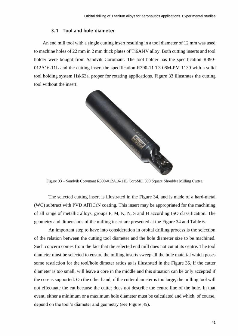
Orbital drilling of Titanium alloys for aeronautics applications. Experimental studies
41
3.1 Tool and hole diameter
An end mill tool with a single cutting insert resulting in a tool diameter of 12 mm was used
to machine holes of 22 mm in 2 mm thick plates of Ti6Al4V alloy. Both cutting inserts and tool
holder were bought from Sandvik Coromant. The tool holder has the specification R390-
012A16-11L and the cutting insert the specification R390-11 T3 08M-PM 1130 with a solid
tool holding system Hsk63a, proper for rotating applications. Figure 33 illustrates the cutting
tool without the insert.
Figure 33 – Sandvik Coromant R390-012A16-11L CoroMill 390 Square Shoulder Milling Cutter.
The selected cutting insert is illustrated in the Figure 34, and is made of a hard-metal
(WC) subtract with PVD AlTiCrN coating. This insert may be appropriated for the machining
of all range of metallic alloys, groups P, M, K, N, S and H according ISO classification. The
geometry and dimensions of the milling insert are presented at the Figure 34 and Table 6.
An important step to have into consideration in orbital drilling process is the selection
of the relation between the cutting tool diameter and the hole diameter size to be machined.
Such concern comes from the fact that the selected end mill does not cut at its centre. The tool
diameter must be selected to ensure the milling inserts sweep all the hole material which poses
some restriction for the tool/hole dimeter ratios as is illustrated in the Figure 35. If the cutter
diameter is too small, will leave a core in the middle and this situation can be only accepted if
the core is supported. On the other hand, if the cutter diameter is too large, the milling tool will
not effectuate the cut because the cutter does not describe the centre line of the hole. In that
event, either a minimum or a maximum hole diameter must be calculated and which, of course,
depend on the tool’s diameter and geometry (see Figure 35).

Orbital drilling of Titanium alloys for aeronautics applications. Experimental studies
42
Figure 34 – CoroMill® 390 insert for milling [44].
Table 6 – Dimensions of the CoroMill® 390 insert [44].
Geometric
parameters
Dimensions
(mm)
w1 6.8
LE 10
S 3.59
BS 1.2
RE 0.8
where:
w1, is the insert width
LE, is the cutting edge effective length
S, is the insert thickness
BS, is the wiper edge length, and
RE, is the corner radius.

Orbital drilling of Titanium alloys for aeronautics applications. Experimental studies
43
Figure 35 – Schematic way to show the differences when choosing different cutting diameters. Adapted from
[45].
Resorting to the tool manufacture information it is possible to select the adequate tool
to machine holes in a range of diameters. In Figure 36 one can observe that the the selected tool
(CoroMill 390) can be used to machine holes in Titanium alloys (S material group) in the range
of diameters 22-34 mm. In addition, knowing the dimensions of the inserts, the minimum and
maximum borehole diameters are calculated using the equations as follows [45]:
𝐷𝑚𝑎𝑥 = 𝐷𝑡×2 − (𝑅𝐸 + 𝐵𝑆) (7)
𝐷𝑚𝑎𝑥 = 12 ×2 − (0.8 + 1.2) = 22 𝑚𝑚 (8)
𝐷𝑚𝑖𝑛 = (𝐷𝑡 − (𝑅𝐸 + 𝐵𝑆)) × 2 (9)
𝐷𝑚𝑖𝑛 = (12 − (0.8 + 1.2)) × 2 = 20 𝑚𝑚 (10)
where:
Dmax, is the maximum diameter of the borehole to be obtained, and
Dmin, is the minimum diameter of the borehole.
Thus, the cutting tool used can generate holes with the diameter range of 20 to 22 mm
and in this thesis, the hole diameter was selected as 22 mm.

Orbital drilling of Titanium alloys for aeronautics applications. Experimental studies
44
Figure 36 – Sandvik’s catalogue, adapted from [45].
For the experimental work, the hole diameters of the specimens were measured with a
3-point Mitutoyo inside micrometre with a range of 20 to 25 mm (see Figure 37). Each diameter
was measured three times in three different random positions.
Figure 37 – Inside micrometre

Orbital drilling of Titanium alloys for aeronautics applications. Experimental studies
45
3.2 Material characterization for orbital drilling tests
The specimen used in the experimental tests were Ti-6Al-4V plates whose chemical
composition can be observed Table 7. Moreover, on the left of the Figure 38 one can see a
picture of the specimen and on the right its dimensions in mm.
Table 7 – Chemical composition of Ti-6Al-4V specimen (% weight).
Al Sn Zr Mo V C Si Mn Cr
% % % % % % % % %
6.01 0.0406 0.0017 0.0096 4.13 0.0607 0.0125 0.0049 0.0345
Ni Fe Cu Nb Pd Ti
% % % % % %
0.0183 0.166 0.0069 0.0383 0.0095 89.5
Figure 38 – Ti-6Al-4V specimen used in orbital drilling tests (dimensions in mm).
Ti-6Al-4V was the chosen material for the experimental tests because, beyond its
popularity, is primarily used at the aerospace industry. Therefore, a lot of researches have been
made within this alpha-beta Ti alloy which makes their characterization easier when compared
with other titanium alloys. In particular, the material characterization for future simulation
purposes is already available in the literature.
The mechanical properties of this alloy can be observed in Table 2 of the Section 2.2.
According to the microstructure, in Figure 39, one can observe a picture, taken in the
metallography laboratory of INEGI, of typical lamellar structure of Ti-6Al-4V with (α+β)
phases processed from casting. Thus, the dark zone is related to the phase β, while the bright is
related to the α phase.

Orbital drilling of Titanium alloys for aeronautics applications. Experimental studies
46
Figure 39 – Typical lamellar structure of Ti-6Al-4V with (α+β) phases.
3.3 Tool Measurement
All cutting inserts were measured prior the tests. This is important in order to allow the
evaluation of tool wear. Therefore, the cutting inserts were marked with a Laser machine (multi-
wave Mopa-M-HP Pulsed Fiber Laser MW-PK-0138-00) as it can be observed on the right of
Figure 40. Additionally, concerning the inserts identification, the same laser was also used to
mark the insert with numbers as can be observed on the left of the Figure 40. In addition, since
each milling insert has two cutting edges, in this thesis an orientation methodology was used
using the already existing round mark (see Figure 40) to define the right side of the insert.
Figure 40 – Milling inserts marked with the laser. Adapted from [44]
Round Mark

Orbital drilling of Titanium alloys for aeronautics applications. Experimental studies
47
The insert measurements were repeated 3 times for each dimension to decrease possible
measuring bias, using a Mitutoyo microscopic (ref: 160869, see Figure 41) with 100x zoom. At
the beginning, all the dimensions were measured to check the ones given by the manufacturer
and correct them if necessary. As the milling insert has a complex geometry hindering the
measurement of the insert thickness, S, a special support was designed and manufactured in
aluminium to facilitate the insert positioning for measuring purposes. The support was painted
in black to avoid the light reflection in the microscope (see Figure 42).
For the tool wear, only the dimensions Xpt, Ypt were used, being these related to the front
cutting edge and the periphery/side cutting edge, respectively. It is important to note that tool
wear tests were not performed in this thesis since only one hole was machined with each of
cutting insert. Nevertheless, any signals of wear after the first hole were possible to check and
also the wear tests can be performed later after this thesis since all the required preparative
measures were taken into account.
Figure 41 – Mitutoyo microscopic used in the insert measurement.
Figure 42 – Milling insert support prepared for measuring purposes.
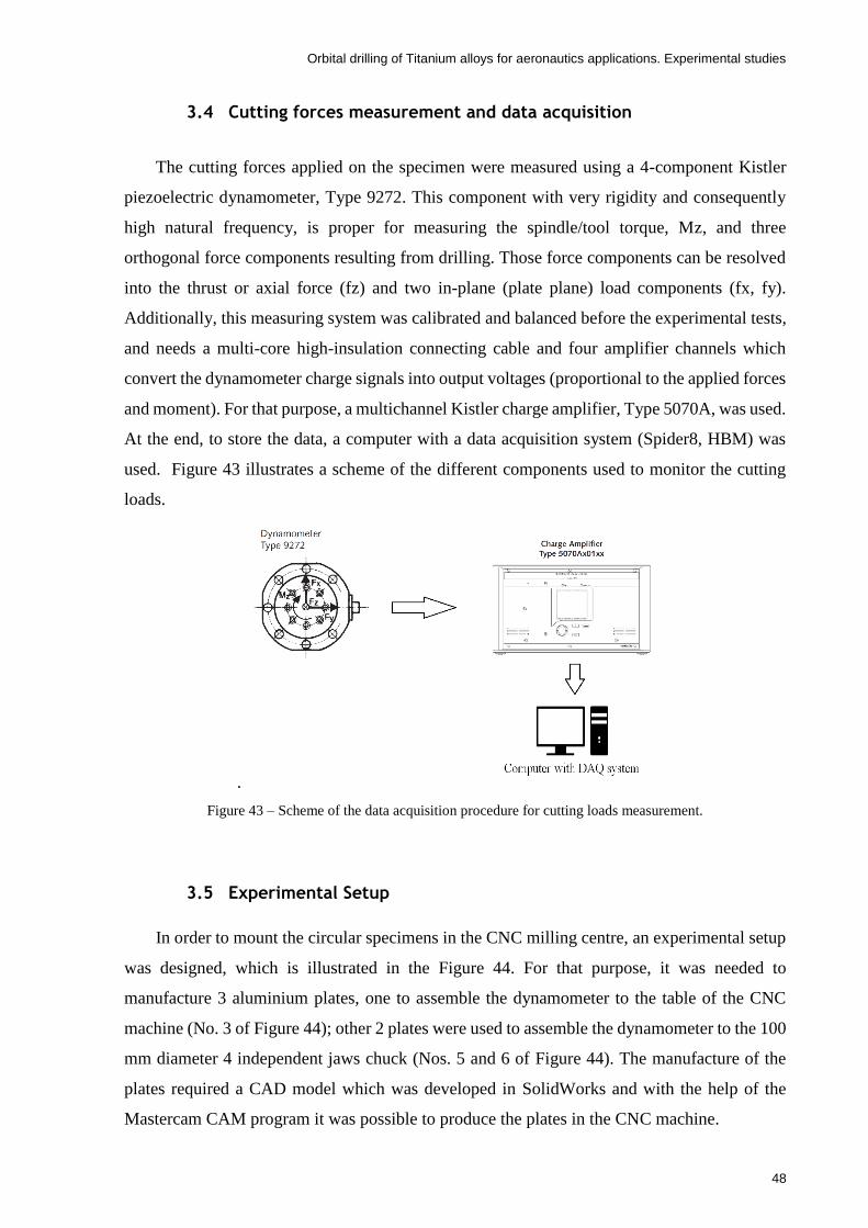
Orbital drilling of Titanium alloys for aeronautics applications. Experimental studies
48
3.4 Cutting forces measurement and data acquisition
The cutting forces applied on the specimen were measured using a 4-component Kistler
piezoelectric dynamometer, Type 9272. This component with very rigidity and consequently
high natural frequency, is proper for measuring the spindle/tool torque, Mz, and three
orthogonal force components resulting from drilling. Those force components can be resolved
into the thrust or axial force (fz) and two in-plane (plate plane) load components (fx, fy).
Additionally, this measuring system was calibrated and balanced before the experimental tests,
and needs a multi-core high-insulation connecting cable and four amplifier channels which
convert the dynamometer charge signals into output voltages (proportional to the applied forces
and moment). For that purpose, a multichannel Kistler charge amplifier, Type 5070A, was used.
At the end, to store the data, a computer with a data acquisition system (Spider8, HBM) was
used. Figure 43 illustrates a scheme of the different components used to monitor the cutting
loads.
.
Figure 43 – Scheme of the data acquisition procedure for cutting loads measurement.
3.5 Experimental Setup
In order to mount the circular specimens in the CNC milling centre, an experimental setup
was designed, which is illustrated in the Figure 44. For that purpose, it was needed to
manufacture 3 aluminium plates, one to assemble the dynamometer to the table of the CNC
machine (No. 3 of Figure 44); other 2 plates were used to assemble the dynamometer to the 100
mm diameter 4 independent jaws chuck (Nos. 5 and 6 of Figure 44). The manufacture of the
plates required a CAD model which was developed in SolidWorks and with the help of the
Mastercam CAM program it was possible to produce the plates in the CNC machine.
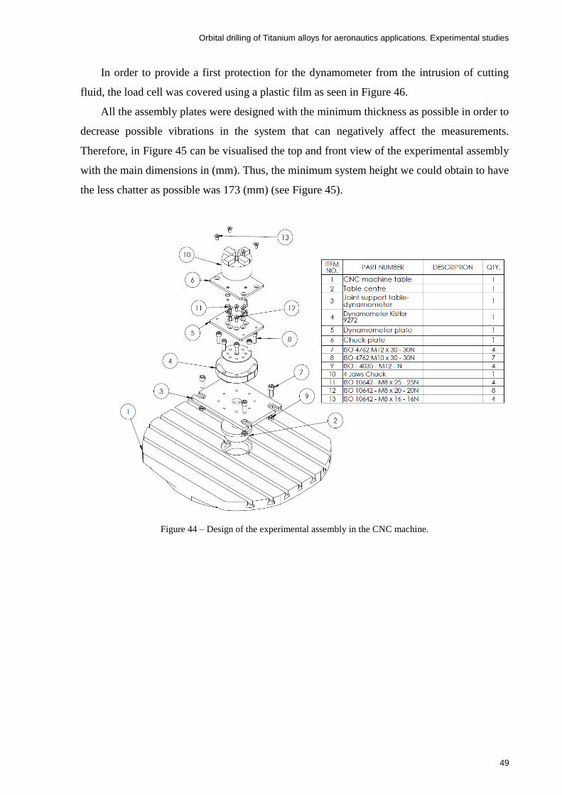
Orbital drilling of Titanium alloys for aeronautics applications. Experimental studies
49
In order to provide a first protection for the dynamometer from the intrusion of cutting
fluid, the load cell was covered using a plastic film as seen in Figure 46.
All the assembly plates were designed with the minimum thickness as possible in order to
decrease possible vibrations in the system that can negatively affect the measurements.
Therefore, in Figure 45 can be visualised the top and front view of the experimental assembly
with the main dimensions in (mm). Thus, the minimum system height we could obtain to have
the less chatter as possible was 173 (mm) (see Figure 45).
Figure 44 – Design of the experimental assembly in the CNC machine.

Orbital drilling of Titanium alloys for aeronautics applications. Experimental studies
50
Figure 45 – Front and top view of the experimental assembly with the essential dimensions in (mm).
Moreover, after one experimental test, it was noticed some (small) vibration coming
from the circular plate specimen being machined. Thus, a special support was designed to
increase the system stiffness, decreasing those little problems due to chatter (see Figure 47).
The support is centred with the chuck and the spindle axis. It has also a central blind hole with
a diameter of 23 mm, which is higher than the 22 mm diameter of the holes to be drilled in the
Ti circular plates. Therefore, the circular plate is supported in the periphery leaving only a 0.5

Orbital drilling of Titanium alloys for aeronautics applications. Experimental studies
51
mm clearance for the hole drilling. The support hole deep was 9.6 mm which was considered
enough to allow an exit for the tool end.
Finally, as can be observed in Figure 46, the specimen is put over the support and fasten
by the 4 jaws chuck, being the experimental work ready to start. Since the chuck has four
independent grips it allows to position the circular plate in non-asymmetry with respect to the
axis of the chuck and spindle but the resulting small eccentricities are not considered relevant
to the tests since the asymmetry may be considered to prevail in the central part of the tests
(border/support effects less important).
Figure 46 – Experimental assembly in the CNC machine with plastic film providing first protection of the load
cell against cutting fluid impact.
Figure 47 – Special specimen support to decrease the cutting vibration, in which (a) is the support assembled and
(b) is the drawing of the support with dimensions.

Orbital drilling of Titanium alloys for aeronautics applications. Experimental studies
52
3.6 Surface roughness measurement
The surface roughness was measured at the CETRIB unit of INEGI with a
Hommelwerke LV-50 roughness gauge, as can be seen in Figure 48. In that order, for each
specimen, the roughness measurement was carried out three times in the axial direction of the
hole surface.
The roughness values considered in this thesis are Ra and Rz parameters. The Ra
parameter gives an average of the roughness measured along the hole surface length, which is
2.1 mm. Besides, Rz parameter is the average of 5 consecutive peak to valley height (see Figure
49).
Figure 48 – Hommelwerke LV-50 roughness gauge
Figure 49 – Types of roughness considered in this experimental work, adapted from [46]

Orbital drilling of Titanium alloys for aeronautics applications. Experimental studies
53
3.7 Machining parameters
In Section 2.4.2 was stated that there are three independent kinematic parameters to
consider in orbital drilling process, which are the spindle speed or rotation frequency n
(rot/min), the feed rate per tooth st (mm/tooth) and the axial feed per orbital revolution a
(mm/rot). However, in Mastercam NC programming software, the input parameters for orbital
drilling are the cutting speed vc (m/min), st, a and the lubrication type (dry/wet), being the
cutting speed directly dependent of the spindle rotation frequency.
Therefore, the selection of the input parameter values was based on the consultation of
existing data available in the literature review about orbital drilling of Ti-6Al-4V and
preliminary machining trials. Nevertheless, this thesis aims to investigate the effects of dry
machining, even though wet machining was also considered for comparison purposes.
Table 8 summarizes a collection of important machining parameters collected during the
literature review. Thus, in this thesis, the parameters selected for the experiments are displayed
in Table 9, which try to encompass the range of parameters observed in the literature. Two
levels for the parameters were defined in order to keep the testing program manageable.
Table 8 – Review of machining parameters for orbital drilling of Ti6Al4V alloy.
Specimen Material Ti-6Al-4V
Reference Tool
Material Lubrication Dh
(mm) Dt
(mm) Z Vc
(m/min) St
(mm/tooth) a
(mm/rot)
[36]
Not Specified
Dry 10 7 2 70 0.05 0.1
70 0.08 0.1
[27]
TiAlN coated solid
carbide
Dry 10 8 3
40 0.05 0.3
40 0.12 0.1
[37]
Not Specified
Wet 10 8 2 20 0.02 0.3
20 0.065 1.1
[21] S105 Wet 10 7 2
70 0.05 0.1
90 0.08 0.2
[22]
Not Specified
Dry 10 6 4 55 0.03 0.15
[33]
WC-8 % Co w/ TiAlN
coating
Dry 10 6 4
100 0.04 0.2
[28]
CrN Coated
solid carbide
Dry/wet/ MQL
10 6 4
45 0.03 0.1
55 0.04 0.15
75 0.05 0.2
95 0.06 0.25
[19] Not
Specified Dry 60 20 5
100~135 0.06~0.09 1.5

Orbital drilling of Titanium alloys for aeronautics applications. Experimental studies
54
Table 9 – Machining Parameters selected for the orbital drilling tests.
Parameters
Experiments
1 2
Vc (m/min) 50 100
St (mm/tooth) 0.04 0.12
a (mm/rot) 0.1 0.3
Lubrication Dry Wet
As can be observed on Table 9, the design of experiments of this thesis contains 2 levels
and 4 input parameters (factors). Thus, the number of experiments that would be performed
based on a full factorial analysis using the levels combination and the machining parameters
are given by 24 = 16 experiments. Therefore, to validate the experiments and decrease the
appearance of possible errors, each experiment will be repeated 2 times. So, the 16 experiments
are multiplied by 3 which gives 48 experimental tests to perform.
However, the experimental methodology of this thesis was made using Taguchi design
of experiments (DOE) and it was possible to reduce the 48 experimental tests to 24, as it is
explained in the following Section 3.8. The significant reduction to a half of experiments
reflects in a reduction of the project costs (tools, lubricant, workpiece material and machine
energy consumption and wear) as well as overall time saving, which is very important
arguments for a short period investigation as imposed by the current MSc programs.
3.8 Experimental Methogology - Taguchi’s DOE
Taguchi and Konishi developed a statistical method named as Taguchi method [47] which
aims to improve the quality of goods produced by any manufacturing process. Meanwhile this
method has been applied to other fields in engineering. Taguchi efforts developing designs to
study variation have been approved by professional statisticians. Thus, a careful selection of
the process parameters and the bifurcation of those into noise and control factors are a crucial
step to obtain success in the achieving of the best results. However, the effect of noise factors
can be decreased with a proper selection of control factors. Besides, in the Taguchi method, the
set of experiments are manipulated by orthogonal arrays (OA) [48].
Therefore, in this thesis, the Tagushi DOE was followed using the control factors as listed
in the Table 9. Such control factors are vc, st, a and the lubrication type. For the DOE purpose,
it was defined for each factor 2 levels. An L8 (27) orthogonal array was selected as illustrated in
Figure 50 and Table 10.

Orbital drilling of Titanium alloys for aeronautics applications. Experimental studies
55
Table 10 – Taguchi L8 (27) orthogonal array selected in this study.
Columns
Experiment Number 1 2 3 4 5 6 7
1 1 1 1 1 1 1 1
2 1 1 1 2 2 2 2
3 1 2 2 1 1 2 2
4 1 2 2 2 2 1 1
5 2 1 2 1 2 1 2
6 2 1 2 2 1 2 1
7 2 2 1 1 2 2 1
8 2 2 1 2 1 1 2
Figure 50 – Taguchi L8 (27) linear graphs, adapted from [49].
In Table 10 one can observe the L8 (27) orthogonal array and in Figure 50 the respective
linear graphs. With this array, the number of distinct experiments to be performed are 8 and the
control factors are put in the columns from 1 to 7. However, it is possible to have 4 control
factors because the 3 remaining columns are for the interactions among those factors. In the
experimental tests of this thesis, there are only 4 control factors, which makes this array with 2
levels the most suitable.
The linear graph used was the one with a triangular shape, as can be observed in Figure
51, because it could be possible to have 1 control factor with no interactions among the other
factors, and that factor would be used for the lubrication condition.
Figure 51 – Linear graph from Taguchi orthogonal array L8 (27) with the respective control factors and
interactions selected for this study, adapted from [49].

Orbital drilling of Titanium alloys for aeronautics applications. Experimental studies
56
Therefore, the design of experiments selected in this thesis is summarized in Table 11.
Table 11 – Taguchi design of experiments.
Experiment
number
Columns
1 2 3 4 5 6 7
vc [m/min]
st [mm/tooth]
Interaction
vc - st a
[mm] Interaction
vc - a
Interaction
st - a
Lubrication
type
1 50 0,04 - 0,1 - - Dry
2 50 0,04 - 0,3 - - Wet
3 50 0,12 - 0,1 - - Wet
4 50 0,12 - 0,3 - - Dry
5 100 0,04 - 0,1 - - Wet
6 100 0,04 - 0,3 - - Dry
7 100 0,12 - 0,1 - - Dry
8 100 0,12 - 0,3 - - Wet
Finally, each experiment must be performed 3 times, which gives a total of 24
experiments. According to this, every experiment was made with a new milling insert because,
as can be observed in the Figure 24, the cutting force values increase along the tool wear. After
obtaining the machining parameters, it was possible to calculate the theoretical machining time
of each experimental test. Thus, knowing that the axial feed velocity is given by:
𝑣𝑓𝑎 = 𝑎 𝑛𝑝 =
𝑇𝑠
𝑡𝑒
(11)
Then, the estimated machining time (seconds), 𝑡𝑒 is
𝑡𝑒 = 𝑎 𝑛𝑝
𝑇𝑠 ×60
(12)
Applying the Equation (6) to the np value,
𝑡𝑒 =
𝑇𝑠 𝜋 (𝐷ℎ − 𝐷𝑐)
𝑠𝑡 𝑍 𝑛 𝑎
(13)
Where:
Ts, is the thickness of the specimen (2.09 mm), and
te, is the estimated machining time.
Therefore, in Table 12, one can visualise the estimated machining time for each experimental
test.

Orbital drilling of Titanium alloys for aeronautics applications. Experimental studies
57
Table 12 – Estimated time for each experimental test.
Experiment
number
Estimated machining
time (seconds)*
1 746.14
2 248.71
3 248.71
4 82.90
5 373.07
6 124.36
7 124.36
8 41.45
*Machining time computed based on only the tool travelling along the specimen thickness.
Finally, the output parameters considered from the experimental program are the thrust
force, in-plane forces, torque, hole surface roughness, hole diameter, chip geometry and burr
formation.

Orbital drilling of Titanium alloys for aeronautics applications. Experimental studies
58
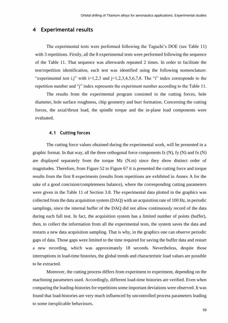
Orbital drilling of Titanium alloys for aeronautics applications. Experimental studies
59
4 Experimental results
The experimental tests were performed following the Taguchi’s DOE (see Table 11)
with 3 repetitions. Firstly, all the 8 experimental tests were performed following the sequence
of the Table 11. That sequence was afterwards repeated 2 times. In order to facilitate the
test/repetition identification, each test was identified using the following nomenclature:
“experimental test i.j” with i=1,2,3 and j=1,2,3,4,5,6,7,8. The “i” index corresponds to the
repetition number and “j” index represents the experiment number according to the Table 11.
The results from the experimental program consisted in the cutting forces, hole
diameter, hole surface roughness, chip geometry and burr formation. Concerning the cutting
forces, the axial/thrust load, the spindle torque and the in-plane load components were
evaluated.
4.1 Cutting forces
The cutting force values obtained during the experimental work, will be presented in a
graphic format. In that way, all the three orthogonal force components fz (N), fy (N) and fx (N)
are displayed separately from the torque Mz (N.m) since they show distinct order of
magnitudes. Therefore, from Figure 52 to Figure 67 it is presented the cutting force and torque
results from the first 8 experiments (results from repetitions are exhibited in Annex A for the
sake of a good concision/completeness balance), where the corresponding cutting parameters
were given in the Table 11 of Section 3.8. The experimental data plotted in the graphics was
collected from the data acquisition system (DAQ) with an acquisition rate of 100 Hz, in periodic
samplings, since the internal buffer of the DAQ did not allow continuously record of the data
during each full test. In fact, the acquisition system has a limited number of points (buffer),
then, to collect the information from all the experimental tests, the system saves the data and
restarts a new data acquisition sampling. That is why, in the graphics one can observe periodic
gaps of data. Those gaps were limited to the time required for saving the buffer data and restart
a new recording, which was approximately 18 seconds. Nevertheless, despite those
interruptions in load-time histories, the global trends and characteristic load values are possible
to be extracted.
Moreover, the cutting process differs from experiment to experiment, depending on the
machining parameters used. Accordingly, different load-time histories are verified. Even when
comparing the loading-histories for repetitions some important deviations were observed. It was
found that load-histories are very much influenced by uncontrolled process parameters leading
to some inexplicable behaviours.

Orbital drilling of Titanium alloys for aeronautics applications. Experimental studies
60
In order to facilitate the analysis of the load results one needs to extract representative
load values from the load-time histories. Therefore, it is important to define a sample of the
load-time history to be representative of the test. In general, the load-history shows an initial
transient that is a result of the tool full engagement in the cutting process. After this initial
transient, load-histories may be stable until the end of the test; in other cases, another transient
may be developed towards the end of the test. In order to clarify the selected interval for the
statistical analysis of the loads, in each graph a black bracket identified with the letter S* was
included. That transient was considered near the starting point of the cutting process. Therefore,
in that zone, the average thrust force (fz) and the average torque (Mz) were computed. In
relation to the in-plane forces, fy and fx, it is important to look for the peak values instead of
average values since the average values resulted approximately null due to the harmonic trend
of those in-plane forces. The high frequency oscillations of load histories are related to the
spindle rotation frequency. Concerning the in-plane loads one can also verify a lower frequency
oscillation which is related to the orbital movement frequency of the tool. The analysis of the
thrust force (fz) histories reveal very distinct behaviours between the tests. Experiments 1.4,
1.6 and 1.8 show a stable plateau and initial and final transients from/towards null thrust loads.
Experiments 1.2 and 1.3 show an initial transient followed by a plateau. Concerning the
remaining experiments, the loads after an initial transient and a relatively small plateau, tend
for a negative or positive value with a magnitude out of the range of the usual values. Those
values seem spurious, particularly the negative values, despite in the literature is reported some
negative thrust forces in drilling operations using helical drills [50]. Those behaviours could be
related to the approaching of the tool to the exit surface of plate and even due to the passing
through the exit surface of the tool.

Orbital drilling of Titanium alloys for aeronautics applications. Experimental studies
61
Figure 52 – Cutting forces of the experimental test 1.1 (vc: 50 m/min; st: 0.04 mm/tooth; a: 0.1 mm/rot and
Lubrication type: Dry).
Figure 53 – Torque of the experimental test 1.1 (vc: 50 m/min; st: 0.04 mm/tooth; a: 0.1 mm/rot and Lubrication
type: Dry).
S*
S*

Orbital drilling of Titanium alloys for aeronautics applications. Experimental studies
62
Figure 54 - Cutting forces of the experimental test 1.2 (vc: 50 m/min; st: 0.04 mm/tooth; a: 0.3 mm/rot and
Lubrication type: Wet).
Figure 55 - Torque of the experimental test 1.2 (vc: 50 m/min; st: 0.04 mm/tooth; a: 0.3 mm/rot and Lubrication
type: Wet).
S*
S*

Orbital drilling of Titanium alloys for aeronautics applications. Experimental studies
63
Figure 56 - Cutting forces of the experimental test 1.3 (vc: 50 m/min; st: 0.12 mm/tooth; a: 0.1 mm/rot and
Lubrication type: Wet).
Figure 57 - Torque of the experimental test 1.3 (vc: 50 m/min; st: 0.12 mm/tooth; a: 0.1 mm/rot and Lubrication
type: Wet).
S*
S*
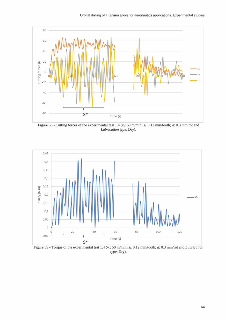
Orbital drilling of Titanium alloys for aeronautics applications. Experimental studies
64
Figure 58 - Cutting forces of the experimental test 1.4 (vc: 50 m/min; st: 0.12 mm/tooth; a: 0.3 mm/rot and
Lubrication type: Dry).
Figure 59 - Torque of the experimental test 1.4 (vc: 50 m/min; st: 0.12 mm/tooth; a: 0.3 mm/rot and Lubrication
type: Dry).
S*
S*
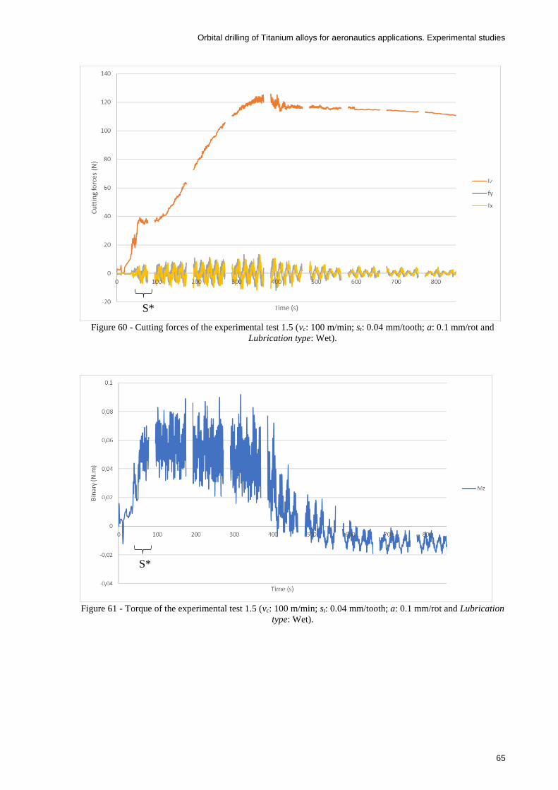
Orbital drilling of Titanium alloys for aeronautics applications. Experimental studies
65
Figure 60 - Cutting forces of the experimental test 1.5 (vc: 100 m/min; st: 0.04 mm/tooth; a: 0.1 mm/rot and
Lubrication type: Wet).
Figure 61 - Torque of the experimental test 1.5 (vc: 100 m/min; st: 0.04 mm/tooth; a: 0.1 mm/rot and Lubrication
type: Wet).
S*
S*

Orbital drilling of Titanium alloys for aeronautics applications. Experimental studies
66
Figure 62 - Cutting forces of the experimental test 1.6 (vc: 100 m/min; st: 0.04 mm/tooth; a: 0.3 mm/rot and
Lubrication type: Dry).
Figure 63 - Torque of the experimental test 1.6 (vc: 100 m/min; st: 0.04 mm/tooth; a: 0.3 mm/rot and Lubrication
type: Dry).
S*
S*

Orbital drilling of Titanium alloys for aeronautics applications. Experimental studies
67
Figure 64 - Cutting forces of the experimental test 1.7 (vc: 100 m/min; st: 0.12 mm/tooth; a: 0.1 mm/rot and
Lubrication type: Dry).
Figure 65 - Torque of the experimental test 1.7 (vc: 100 m/min; st: 0.12 mm/tooth; a: 0.1 mm/rot and Lubrication
type: Dry).
S*
S*

Orbital drilling of Titanium alloys for aeronautics applications. Experimental studies
68
Figure 66 - Cutting forces of the experimental test 1.8 (vc: 100 m/min; st: 0.12 mm/tooth; a: 0.3 mm/rot and
Lubrication type: Wet).
Figure 67 - Torque of the experimental test 1.8 (vc: 100 m/min; st: 0.12 mm/tooth; a: 0.3 mm/rot and Lubrication
type: Wet).
Figure 68 and Figure 69 show the mean values of the thrust force and torque of each
experiment number. The averaged values resulted from the average between the three
repetitions. Furthermore, Figure 70 displays the averages of the peak values of the in-plane
forces, fy and fx. This figure also accounts for the averaged results of the 3 test repetitions. It
is important to note that concerning the evaluation of the representative load values, the same
time samplings were used for the first test and its repetitions.
As is observed in the Figure 68, the experiments No. 7 and 1 show the lowest thrust
forces, while experiments No. 2, 4, 6 and 8 exhibit the larger values. In fact, experiment No. 7
and 1 are performed with the lowest axial feed per orbital revolution, while the experiments
No. 2, 4, 6 and 8 showed the biggest values of this machining parameter. A bigger axial feed
S*
S*

Orbital drilling of Titanium alloys for aeronautics applications. Experimental studies
69
will increase the material removal rate in every helical revolution. Therefore, the applied thrust
force to remove more material per each helical revolution is also larger. The maximum thrust
force registered was observed for the experiments No. 4 and 8 which, simultaneously have the
biggest feed/tooth and axial feed. On the other hand, the experiment No. 1 corresponds to the
one with lower feed/tooth and axial feed. The experiment No. 5 was performed with the same
axial and tangential feed conditions of the experiment No. 1, but shows slightly higher thrust
forces which could be justified by the different cutting speed.
According to the Figure 69, one can note that the experimental tests with the largest
feeds (axial and tangential), have recorded the highest torque, as is the case of the experiment
No. 4 and 8. On the other hand, the lowest torque was verified in the experiment No.1, which
corresponds to the lower feed/tooth and axial feed. Moreover, the experiment No.4 also
corresponds to the lowest feeds, either in axial or tangential direction, however the respective
torque is slightly larger when compared with the experiment No.1 due to the larger cutting
speed.
Analysing the Figure 70, it can be perceived that the experimental test with the largest
feeds, either in the axial or tangential directions, have recorded the highest in-plane forces, as
is the case of the experiments No. 4 and 8. On the other hand, the lowest in-plane forces were
recorded in the experiments No. 5 and 1, which have the lowest feeds (axial and tangential).
Other interesting consideration is to verify the kinematics of the process by the
visualization of the graphs. Figure 71 represents a sample of the in-plane forces for
experimental test 1.1, for a time range 1 second. There can be noticed that fx and fy forces show
the same periodic oscillation but in out-of-phasing. The phase angle should be approximately
90 degrees. Moreover, the counting of peaks, either in fx or fy force, gives enough information
to know the spindle frequency (and indirectly the cutting speed) defined in the input machining
parameters. Each peak corresponds to one tool rotation. Thus counting 22 peaks in a second,
means that the spindle speed rotation is equal to 22. Therefore, and applying the Equation (4)
in Section 2.4.2, the cutting speed is equal to 49.8 m/min, being approximately equal to the 50
m/min specified as input parameter of the process.
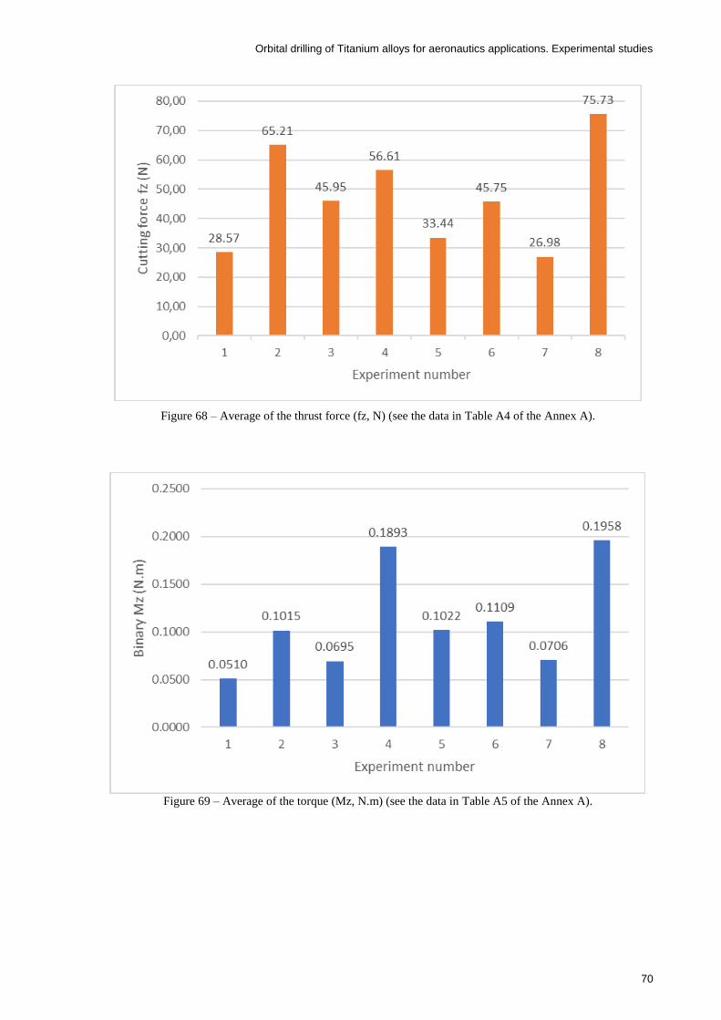
Orbital drilling of Titanium alloys for aeronautics applications. Experimental studies
70
Figure 68 – Average of the thrust force (fz, N) (see the data in Table A4 of the Annex A).
Figure 69 – Average of the torque (Mz, N.m) (see the data in Table A5 of the Annex A).
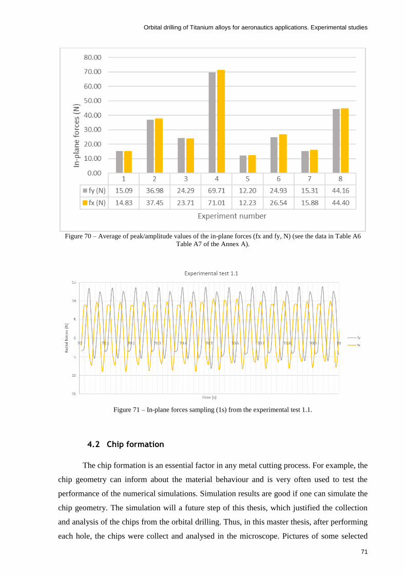
Orbital drilling of Titanium alloys for aeronautics applications. Experimental studies
71
Figure 70 – Average of peak/amplitude values of the in-plane forces (fx and fy, N) (see the data in Table A6
Table A7 of the Annex A).
Figure 71 – In-plane forces sampling (1s) from the experimental test 1.1.
4.2 Chip formation
The chip formation is an essential factor in any metal cutting process. For example, the
chip geometry can inform about the material behaviour and is very often used to test the
performance of the numerical simulations. Simulation results are good if one can simulate the
chip geometry. The simulation will a future step of this thesis, which justified the collection
and analysis of the chips from the orbital drilling. Thus, in this master thesis, after performing
each hole, the chips were collect and analysed in the microscope. Pictures of some selected

Orbital drilling of Titanium alloys for aeronautics applications. Experimental studies
72
representative chips from each experimental test, taken with an Olympus DP12, can be
observed in the Figure 72 and Figure 73.
In the Figure 73, there is a missing picture from the experimental test 2.5, which is
justified by a technical problem. During the experimental work, a fibre glass fabric used to
collect the chips grasped accidently to the spindle projecting the chips. Nevertheless, as the
chips taken from the experimental tests 1.5 and 3.5 were similar, it was decided not repeat the
test.
Figure 72 – Pictures of the chips from the experiments No. 1 to 4, including the repetitions. The number in the
images refers to the experimental test number.
1.1 2.1 3.1
1.2 2.2 3.2
1.3 2.3 3.3
1.4 2.4 3.4
A
B

Orbital drilling of Titanium alloys for aeronautics applications. Experimental studies
73
Figure 73 - Pictures of the chips from the experiments No. 5 to 8, including the repetitions. The number in the
images refers to the experimental test number.
The analysis of the chip geometries reveals differences in the chip width and length
among the distinct experiments. In the orbital drilling process, there is a continuous cut in the
axial direction and a discontinuous cut in the in-plane directions. Thus, the discontinuous cut
originates shorter and thicker chip fragments and the continuous one creates thinner and longer
chips. That can be observed, for example, in the experimental test 2.4 of the Figure 72, where
one can note one thick chip (letter A) resulted from the discontinuous cut, and three other chips
(letter B) resulted from the continuous cut. In addition, as the chips are scattered, the process
of separate those coming from the discontinuous and continuous cut is not easy. Besides, some
continuous chips appear to be more straight, and the others wavy.
Some repetitions revealed significant changes in the chip geometry confirming
important scatter in the test results that was already verified in the load-time histories
1.5 3.5
1.6 2.6 3.6
1.7 2.7 3.7
1.8 2.8 3.8
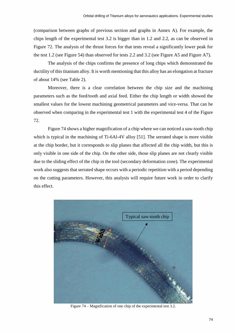
Orbital drilling of Titanium alloys for aeronautics applications. Experimental studies
74
(comparison between graphs of previous section and graphs in Annex A). For example, the
chips length of the experimental test 3.2 is bigger than in 1.2 and 2.2, as can be observed in
Figure 72. The analysis of the thrust forces for that tests reveal a significantly lower peak for
the test 1.2 (see Figure 54) than observed for tests 2.2 and 3.2 (see Figure A5 and Figure A7).
The analysis of the chips confirms the presence of long chips which demonstrated the
ductility of this titanium alloy. It is worth mentioning that this alloy has an elongation at fracture
of about 14% (see Table 2).
Moreover, there is a clear correlation between the chip size and the machining
parameters such as the feed/tooth and axial feed. Either the chip length or width showed the
smallest values for the lowest machining geometrical parameters and vice-versa. That can be
observed when comparing in the experimental test 1 with the experimental test 4 of the Figure
72.
Figure 74 shows a higher magnification of a chip where we can noticed a saw-tooth chip
which is typical in the machining of Ti-6Al-4V alloy [51]. The serrated shape is more visible
at the chip border, but it corresponds to slip planes that affected all the chip width, but this is
only visible in one side of the chip. On the other side, those slip planes are not clearly visible
due to the sliding effect of the chip in the tool (secondary deformation zone). The experimental
work also suggests that serrated shape occurs with a periodic repetition with a period depending
on the cutting parameters. However, this analysis will require future work in order to clarify
this effect.
Figure 74 – Magnification of one chip of the experimental test 3.2.
Typical saw-tooth chip
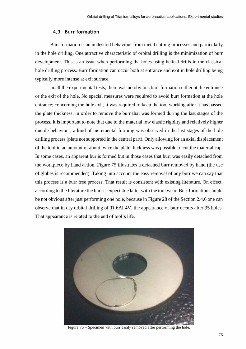
Orbital drilling of Titanium alloys for aeronautics applications. Experimental studies
75
4.3 Burr formation
Burr formation is an undesired behaviour from metal cutting processes and particularly
in the hole drilling. One attractive characteristic of orbital drilling is the minimization of burr
development. This is an issue when performing the holes using helical drills in the classical
hole drilling process. Burr formation can occur both at entrance and exit in hole drilling being
typically more intense at exit surface.
In all the experimental tests, there was no obvious burr formation either at the entrance
or the exit of the hole. No special measures were required to avoid burr formation at the hole
entrance; concerning the hole exit, it was required to keep the tool working after it has passed
the plate thickness, in order to remove the burr that was formed during the last stages of the
process. It is important to note that due to the material low elastic rigidity and relatively higher
ductile behaviour, a kind of incremental forming was observed in the last stages of the hole
drilling process (plate not supported in the central part). Only allowing for an axial displacement
of the tool in an amount of about twice the plate thickness was possible to cut the material cap.
In some cases, an apparent bur is formed but in those cases that burr was easily detached from
the workpiece by hand action. Figure 75 illustrates a detached burr removed by hand (the use
of globes is recommended). Taking into account the easy removal of any burr we can say that
this process is a burr free process. That result is consistent with existing literature. On effect,
according to the literature the burr is expectable latter with the tool wear. Burr formation should
be not obvious after just performing one hole, because in Figure 28 of the Section 2.4.6 one can
observe that in dry orbital drilling of Ti-6Al-4V, the appearance of burr occurs after 35 holes.
That appearance is related to the end of tool’s life.
Figure 75 – Specimen with burr easily removed after performing the hole.

Orbital drilling of Titanium alloys for aeronautics applications. Experimental studies
76
4.4 Diameter deviation
The diameter accuracy is an important indicator to the machine hole quality. In this
study, the nominal diameter to be obtained in the specimens was 22 mm. However, in orbital
drilling process as well as in conventional drilling, there are always small discrepancies in the
value of the diameter experimentally obtained when compared to the nominal values. Moreover,
as the cutting process moves forward through the hole, the length of contact between the tool
and the workpiece increases, and therefore, the radial cutting efforts are also larger [52]. In
addition to that, increasing the radial cutting forces will increment tool deflection, leading to
smaller size holes. Also the Ti-6Al-4V alloy shows higher elastic spring-back due to the lower
elastic stiffness (approximately half of the steel) which also contributes to lower hole diameters
with respect to the nominal hole size specified in the CAM software [22].
Figure 76 represents the averaged diameters measured in the machined holes in all the
experimental tests. As specified in Chapter 3, the diameters were measured with a 3-point
Mitutoyo diameter micrometre and three measurements performed for each hole. See Table
A1of the Annex A for the detailed values of the measurements. As can be noticed in Figure
76, the experiment number 1 recorded the closest hole diameter to the nominal value of 22 mm,
and it was the one with the lower values of cutting parameters (cutting speed, feed/tooth and
axial feed), which resulted in lower cutting forces. One can conclude that the obtained diameter
varied from 21.83 to 21.89 mm which represents a range of 60 µm, which is considered a good
reproducible process. With this information, we can act on CAM software to reduce the
deviation from the nominal values. That correction should be dependent on the cutting
parameters.
Figure 76 – Hole diameters after the experimental drilling tests.

Orbital drilling of Titanium alloys for aeronautics applications. Experimental studies
77
4.5 Roughness
Concerning the geometrical features of drilled holes, we can discuss the deviations of
the real diameter of the holes with respect to the nominal one, deviations from circularity and
also the surface roughness. In this study the deviation from circularity was not assessed but
orbital drilling has been recognized as a process that produce better tolerances than classical
drilling. Concerning the deviations of the average diameter it was discussed in the previous
section and despite a deviation has been verified, it could be corrected after some preliminary
tests. Finally, the roughness of the surface holes obtained by orbital drilling is a very important
advantage comparing with traditional drilling process. In order to verify this aspect this section
presents the roughness values measured for each hole accordingly the procedures depicted in
Section 3.6. Figure 77 presents the average of the roughness values Ra (µm) for the three
repetitions (see the data in the Table A2 of the Annex A). Additionally, in Figure 78 it is shown
an average of the roughness values Rz (µm) for the three repetitions (see the data in the Table
A3 of the Annex A).
As can be observed in both Figure 77 and Figure 78, for the worst case scenario, which
would be the experimental test No.7, the surface roughness, Ra and Rz, obtained in the
specimens were 0.277 and 1.484, respectively. Under this circumstances, using these values of
Rz and Ra, in Figure 79 was drawn a blue, a red line and two black dots in order to help the
visualization of those roughness values inserted in a roughness – manufacturing process chart.
There can be noticed that the surface finish of the holes made in orbital drilling process is much
better than the ones obtained by conventional drilling process. In fact, within metal cutting
processes, it has the order of magnitude of roughness values from polishing which is an abrasive
finishing method used to give better surface quality to the workpieces.
In general, the variations in surface roughness occurred in a narrow range. Only
experiments 6 and 7 showed slightly higher values. They were performed under dry conditions,
but they show opposed feed/tooth and axial feed values and same cutting speed. It is interesting
to note that the lower feed/tooth associated to the higher axial feed have the same influence in
the roughness as the opposite parameters combination. The theoretical cutting times for these
two tests were approximately the same.

Orbital drilling of Titanium alloys for aeronautics applications. Experimental studies
78
Figure 77 – Ra surface roughness measurements.
Figure 78 – Rz surface roughness measurements.

Orbital drilling of Titanium alloys for aeronautics applications. Experimental studies
79
Figure 79 – Roughness chart with a red and a blue line defined by the values obtained in this thesis experimental
work, adapted from [53].

Orbital drilling of Titanium alloys for aeronautics applications. Experimental studies
80
4.6 Tool wear
Each experimental test (each hole) was performed with always a new insert ir order to
avoid any influence of tool wear. Also, this will allow the investigation of cutting parameters
in tool wear analysis, for future works. Nevertheless, and to be sure about any tool wear after
performing one hole, the inserts were measured before and after the first hole (results presented
in Table 13). As can be noticed in Table 13, there are no significant wear after just performing
one hole. In accordance with Figure 31 from literature, the tool wear is often observed after
performing around 10 holes in which, during flood and dry conditions, can be observed a tool
wear around 0.025 mm and 0.05 mm, respectively. Thus, the values observed in Table 13
confirms that there is not any noticeable tool wear of tool damage since any measured tool wear
are in the range of measuring error. A proof of this is the negative wear values.
However, for further investigation, all this work will save a lot of time in order to
perform a tool wear/damage analysis in the orbital drilling process.
Table 13 – Tool wear after the performance of one hole.
New tool After 1 hole Tool wear
Experimental test
Ypt (mm)
Xpt (mm)
Ypt (mm)
Xpt (mm)
Ypt (mm)
Xpt (mm)
1.1 1.458 1.843 1.442 1.837 0.016 0.006
1.2 1.454 1.997 1.453 2.002 0.001 -0.004
1.3 1.395 1.898 1.384 1.892 0.011 0.006
1.4 1.500 1.843 1.495 1.845 0.005 -0.002
1.5 1.489 1.948 1.475 1.956 0.015 -0.008
1.6 1.434 2.044 1.428 2.043 0.006 0.001
1.7 1.476 2.011 1.468 2.008 0.008 0.003
1.8 1.486 2.050 1.471 2.048 0.015 0.002
2.1 1.984 1.317 1.983 1.307 0.001 0.011
2.2 1.474 1.782 1.473 1.782 0.000 0.000
2.3 1.470 2.010 1.468 2.004 0.001 0.007
2.4 1.261 2.087 1.266 2.081 -0.005 0.006
2.5 1.425 2.021 1.424 2.008 0.001 0.013
2.6 1.351 1.920 1.359 1.908 -0.008 0.012
2.7 1.456 2.029 1.460 2.017 -0.003 0.013
2.8 1.452 2.005 1.460 1.986 -0.008 0.019
3.1 1.363 1.788 1.359 1.785 0.004 0.003
3.2 1.380 1.670 1.383 1.661 -0.003 0.009
3.3 1.493 1.999 1.483 2.003 0.010 -0.004
3.4 1.486 1.952 1.478 1.945 0.008 0.007
3.5 1.539 2.112 1.526 2.102 0.013 0.011
3.6 1.575 1.893 1.583 1.889 -0.008 0.004
3.7 1.075 0.680 1.070 0.666 0.005 0.014
3.8 2.177 1.605 2.172 1.593 0.005 0.012

Orbital drilling of Titanium alloys for aeronautics applications. Experimental studies
81
5 Taguchi’s DOE analysis
The analysis of results from Taguchi’s Design of Experiments is very important to
understand the effect of the input cutting parameters (factors) into the output results (dependent
variables). Moreover, it is also possible to know the interactions among input parameters and
their influence into the output results. Thus, the analysis of variance (ANOVA) was performed
to the results of the experimental tests which included the diameter, in-plane forces, thrust
forces, torque and surface roughness. That analysis aims to identify the input cutting parameters
that most influence the dependent variables of the process, and to assess their influence on the
variations of the dependent variables. Therefore, the performed analysis will potentially allow
identifying the best level of control factors that may lead to the best performance of the
manufacturing process, in particular the orbital drilling. Besides the ANOVA, the analysis of
means was performed, both analysis resorting to the Super Anova software, version 1.1.
Important information to extract from the ANOVA is the contribution of each input
parameters on the outputs of the process, including the contributions of the interactions of the
input parameters. Therefore, and after performing the ANOVA, the percentage contributions
were calculated using the Equation (14), and presented in Table 14.
𝑃𝐴 =
(𝑆𝑢𝑚 𝑜𝑓 𝑠𝑞𝑢𝑎𝑟𝑒𝑠𝐴 − (𝑟𝑒𝑠𝑖𝑑𝑢𝑎𝑙 𝑚𝑒𝑎𝑛 𝑠𝑞𝑢𝑎𝑟𝑒×𝑑𝑓𝐴))
𝑇𝑜𝑡𝑎𝑙 𝑜𝑓 𝑡ℎ𝑒 𝑠𝑢𝑚 𝑜𝑓 𝑠𝑞𝑢𝑎𝑟𝑒𝑠
(14)
where,
A is the input parameter/interaction of parameters;
PA is the contribution percentage of each factor;
dfA are the degrees of freedom associated to factor A.
The data required for the application of Equation (14) is presented individually for each
dependent variable in its respective ANOVA tables (see Table 15, Table 16, Table 17, Table
18, Table 19 and Table 20). As can be noticed in Table 14, only for the in-plane forces, fx and
fy, the source of variations can be significantly attributed to the controlled factors variation
because only a residual influence of about 11 % was verified for both cases. This means that
only 11% of the results variation is not explained by variations of the source parameters, being
that attributed to noise and uncontrollable factors. It is verified that the axial feed is responsible
for about 50% of variation in the in-plane forces, followed by the feed/tooth (approx. 17%) and
the cutting speed (approx. 10%).
Regarding the thrust force, fz, the torque and the diameter, only about half of the
variations of this dependent variable are justified by the variations of the input factors. In these

Orbital drilling of Titanium alloys for aeronautics applications. Experimental studies
82
cases, noise or other uncontrolled factors are responsible for the other half variations of the
dependent variables which is considered a very important drawback for the establishment of
strong conclusions. Nevertheless, it seems that axial feed is responsible for about 30% of
variations of fz as well the lubrication condition justifies 20% of variation of this dependent
variable. Concerning the diameter, seems that axial feed and its interaction with other factors
are the most important factors for the variations.
At last, the surface roughness (Ra or Rz) variations are mostly due to uncontrolled
factors, according to a contribution percentage of around 80 %. Nevertheless, it is interesting
to note that surface roughness variations were very small and less sensitive to the factors
variation. This means that the range of factors variation despite being a typical range of practical
interest it leads to significantly constant surface roughness’s and very good surface finishings.
More significant effects of the input parameters in the outputs could likely be obtained if one
would explore the cutting parameters in regimes without practical interest. It is worthwhile to
note that cutting speed has a non-null influence on roughness. In the following subsections, a
more detailed discussion of ANOVA for each of the investigated parameter is presented.
5.1 Diameter analysis
Table 15 shows the analysis of variance performed for the hole diameter. Statistically,
only the results calculated for either a confidence interval of 95% or a significance level of 5%
are assumed reliable and therefore accepted. In that order, only the P-values (proof value) below
0.05 are statistically acceptable for the confidence interval referred above, as it is the case of
axial feed and the interactions cutting speed-axial feed and feed/tooth-axial feed. The other
results with a P-value higher than 0.05, despite may still provide some useful information, they
are not statistically representative. These last results are shown in Annex B from the Figure B1
to Figure B26, for the sake of comprehensiveness. Moreover, in annex C is presented the means
tables which include the detailed data from the graphs of the mean analysis.

Orbital drilling of Titanium alloys for aeronautics applications. Experimental studies
83
Table 14 – Contribution percentage of the cutting parameters in the output results.
Factor (A) Diameter
(mm) Fx_max
(N) Fy_max
(N) Fz (N)
Mz (N.m)
Ra
(µm)
Rz
(µm)
Sources of variation
P, Contribution percentage %
Principal effects Cutting speed [m/min] 1.35 9.29 10.21 0.00 0.00 13.99 14.30
Feed/tooth [mm] 0.00 16.88 17.57 0.00 8.21 0.00 0.00
Axial feed [mm] 17.14 53.40 51.35 31.21 35.40 0.00 0.00
Lubrication 0.10 0.01 0.00 25.94 0.00 0.00 3.49
Interactions
Cutting speed [m/min] * Feed/tooth [mm]
4.60 1.40 1.20 0.00 0.00 0.00 0,00
Cutting speed [m/min] * Axial feed [mm]
11.37 2.66 2.41 0.00 0.00 0.00 0.00
Feed/tooth [mm] * Axial feed [mm]
11.37 5.96 6.38 1.60 11.89 4.09 4.05
Residual (error) 54.07 10.40 10.88 41.25 44.50 81.92 78.16
TOTAL 100 100 100 100 100 100 100
Table 15 – Analysis of variance for diameter.
Figure 80 represents the variation of diameter with axial feed (statistically
representative) with the respective confidence intervals. Linear variation is assumed which is a
limitation of the two levels DOE. One can notice that the increase of the axial feed from 0.1 to
0.3 mm, decreases the final hole diameter from 21.86 mm to 21.84 mm. That fact may be
explained because the tool deflection rises with the increase of the axial feed due to the
increasing cutting forces. This trend is confirmed by Denkena, et al. [27] results, which are
plotted in the Figure 81.

Orbital drilling of Titanium alloys for aeronautics applications. Experimental studies
84
Figure 80 – Effect of the axial feed in the hole diameter.
Figure 81 – Influence of the axial and tangential feed/tooth in the hole diameter, adapted from [27].
As concerns the interactions among parameters, P-values of the interactions cutting
speed-feed/tooth, cutting speed-axial feed and feed/tooth-axial feed are 0.1088, 0.302 and

Orbital drilling of Titanium alloys for aeronautics applications. Experimental studies
85
0.302, respectively. In that order, only the interactions cutting speed-axial feed and axial feed-
feed/tooth show values within the confidence interval of 95 % (statistical significant).
Analysing the interaction between the cutting speed and the axial feed, Figure 82, one
can realize that with a cutting speed of 50 m/min, the mean of hole diameter tends to decrease
from 21.87 mm to 21.83 mm when the axial feed rises from 0.1 to 0.3 mm. On the other hand,
with a cutting speed of 100 m/min, the hole diameter value tends to be stable in 21.84 mm with
the same variation of the axial feed. Therefore, the axial feed influence is only relevant for
lower cutting speeds.
Figure 83 shows the effect of the interaction between the input parameters feed/tooth
and axial feed in the mean diameter of hole. There is no variation in the hole diameter value of
21.85 mm using a feed/tooth of 0.12 mm/tooth, varying the axial feed from 0.1 mm to 0.3 mm.
On the other hand, the hole diameter tends to decrease from 21.87 mm to 21.83 mm, using a
feed/tooth of 0.04 mm/tooth, varying the axial feed from 0.1 mm to 0.3 mm.
Thus, in order to get diameters more insensitive to the axial feed one needs to combine
higher cutting speeds with higher feed per tooth values. Using this information, it is possible to
propose corrections in CAM software to get controlled diameters within tight tolerances.
Figure 82 - Effect of the interaction between the input parameters cutting speed and axial feed in the hole
diameter.

Orbital drilling of Titanium alloys for aeronautics applications. Experimental studies
86
Figure 83 - Effect of the interaction between the input parameters feed/tooth and axial feed in the hole diameter.
5.2 In-plane forces analysis
With reference to the in-plane forces, it is desirable to obtain lower forces, so that tools
are subjected to lower cutting efforts, leading consequently to higher tool lives and less tool
deflections. The in-plane forces are a characteristic of orbital drilling which are not visible in
classical drilling, using helical drills. Since fx ad fy show similar behaviours, in this chapter
only fx load component will be analysed for the sake of concision.
Table 17 shows the ANOVA relative to the in-plane load component, fx, for the studied
factors, the cutting speed, feed/tooth, axial feed, lubrication condition and some interactions
cutting speed-feed/tooth, cutting speed-axial feed, feed/tooth-axial feed. According to the P-
values computed, one can conclude that cutting speed, feed/tooth and axial feed factors
(statistically) significantly (95% confidence interval; P<0.05) influence the studied load
variation (fx). The interactions cutting speed-feed/tooth and cutting speed–axial feed are also
statistically significant as can be verified in ANOVA table. Lubrication condition influence is
not statistically significant for the confidence interval of 95 %.
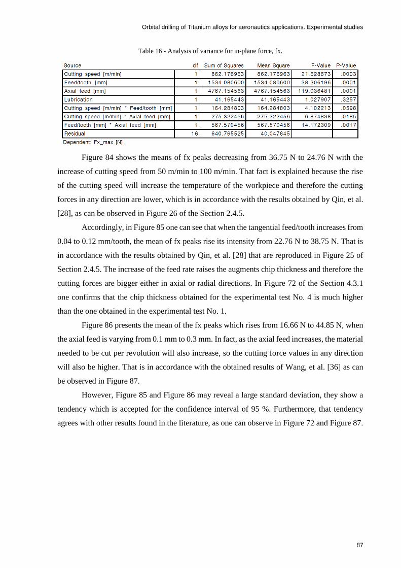
Orbital drilling of Titanium alloys for aeronautics applications. Experimental studies
87
Table 16 - Analysis of variance for in-plane force, fx.
Figure 84 shows the means of fx peaks decreasing from 36.75 N to 24.76 N with the
increase of cutting speed from 50 m/min to 100 m/min. That fact is explained because the rise
of the cutting speed will increase the temperature of the workpiece and therefore the cutting
forces in any direction are lower, which is in accordance with the results obtained by Qin, et al.
[28], as can be observed in Figure 26 of the Section 2.4.5.
Accordingly, in Figure 85 one can see that when the tangential feed/tooth increases from
0.04 to 0.12 mm/tooth, the mean of fx peaks rise its intensity from 22.76 N to 38.75 N. That is
in accordance with the results obtained by Qin, et al. [28] that are reproduced in Figure 25 of
Section 2.4.5. The increase of the feed rate raises the augments chip thickness and therefore the
cutting forces are bigger either in axial or radial directions. In Figure 72 of the Section 4.3.1
one confirms that the chip thickness obtained for the experimental test No. 4 is much higher
than the one obtained in the experimental test No. 1.
Figure 86 presents the mean of the fx peaks which rises from 16.66 N to 44.85 N, when
the axial feed is varying from 0.1 mm to 0.3 mm. In fact, as the axial feed increases, the material
needed to be cut per revolution will also increase, so the cutting force values in any direction
will also be higher. That is in accordance with the obtained results of Wang, et al. [36] as can
be observed in Figure 87.
However, Figure 85 and Figure 86 may reveal a large standard deviation, they show a
tendency which is accepted for the confidence interval of 95 %. Furthermore, that tendency
agrees with other results found in the literature, as one can observe in Figure 72 and Figure 87.
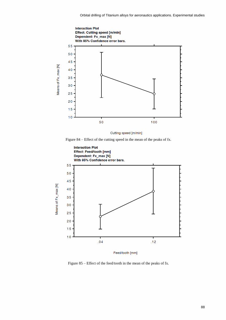
Orbital drilling of Titanium alloys for aeronautics applications. Experimental studies
88
Figure 84 – Effect of the cutting speed in the mean of the peaks of fx.
Figure 85 – Effect of the feed/tooth in the mean of the peaks of fx.

Orbital drilling of Titanium alloys for aeronautics applications. Experimental studies
89
Figure 86 - Effect of the axial feed in the mean value of the peaks of fx.
Figure 87 - Variation of the cutting forces with the increase of the depth of cut, adapted from [36].
In respect to the interactions among parameters, in Figure 88 one realize that with a
cutting speed of 50 mm/min, when the feed/tooth rises from 0.04 mm/tooth to 0.12 mm/tooth,
the mean of the fx peaks changes from 26.14 N to 47.36 N. Moreover, with a cutting speed of
100 m/min, when the feed/tooth rises from 0.04 mm/tooth to 0.12 mm/tooth, the mean of the fx
peaks rises from 19.38 N to 30.14 N. Thus, for higher cutting speeds the influence of the

Orbital drilling of Titanium alloys for aeronautics applications. Experimental studies
90
feed/tooth on fx peaks is less important than for lower cutting speeds. However, as it was
explained above, this is just an apparent tendency because the P-value of this interaction is
slightly above 0.05, so statistically not significant taking into account the P-value threshold
assumed.
In Figure 89 can be noticed that the means of the fx peaks rise from 19.67 N to 54.23 N
when the feed/tooth increases from 0.04 mm/tooth to 0.12 mm/tooth with the cutting speed of
50 m/min. Moreover, with a cutting speed of 100 m/min, with the same increase of feed/tooth,
the means of the fx peaks also increase, however with smaller values, from 14.05 N to 36.47 N.
This interaction effect is similar to that between the cutting speed and feed/tooth.
Finally, as can be observed in Figure 90, with a feed/tooth of 0.04 mm/tooth, the means
of fx peaks increments from 13.53 N to 32 N when the axial feed increases from 0.1 mm/rev to
0.3 mm/rev. Additionally, with a feed/tooth of 0.12 mm/tooth, the means of the fx maximums,
however larger, also increases from 19.79 N to 57.71 N, when the axial feed increases from 0.1
mm to 0.3 mm. In this case, the axial feed influence on fx peaks is more important for higher
feed/tooth.
Thus, in order to obtain the lowest in-plane cutting forces, the best cutting parameters
selection would be higher cutting speeds combined with lowers axial feed and feed/tooth.
Figure 88 - Effect of the interaction between the cutting speed-feed/tooth in the fx peaks.
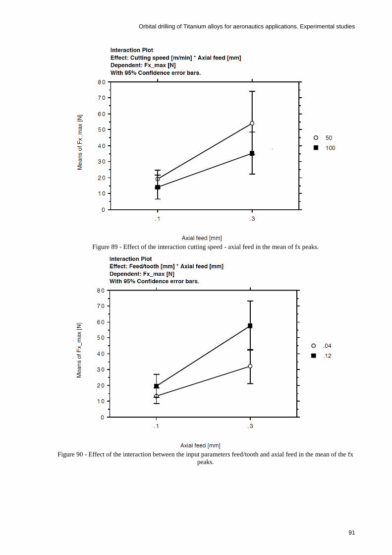
Orbital drilling of Titanium alloys for aeronautics applications. Experimental studies
91
Figure 89 - Effect of the interaction cutting speed - axial feed in the mean of fx peaks.
Figure 90 - Effect of the interaction between the input parameters feed/tooth and axial feed in the mean of the fx
peaks.

Orbital drilling of Titanium alloys for aeronautics applications. Experimental studies
92
5.3 Thrust force
In respect to the thrust force, it is desirable, as well as in other cutting loads, to reduce
tool wear and power consumption.
In Table 17 one can realize that the axial feed and the lubrication type show P-values in
the order of statistically significance. These two factors have been identified before as the most
influencing ones in the thrust force (see Table 14). None of the interactions are statistically
significant taking into account a significance level of 5 %.
Table 17 - Analysis of variance for thrust force, fz.
Thus, considering only the values within the level of significance of 5 %, Figure 91
shows that the thrust force fz increases from 38.56 N to 60.86 N, when the axial feed increases
from 0.1 mm to 0.3 mm. That fact is in concordance with Qin, et al. [28] results that can be
observed in Figure 27. In fact, as the axial feed increases, the material needed to be cut per
revolution also increases which leads to larger thrust forces in the specimen.
Finally, the results of this study points to bigger thrust forces using a flood coolant which
is used when comparing with dry machining (see Figure 92). These results do not correspond
with the literature as can be observed in the Figure 25, Figure 26 and Figure 27. However, the
type of tool is different, and in fact, the lack of lubricant will increase the temperature of the
workpiece that may soften the material, leading to lower cutting forces. On the other hand, the
ANOVA revealed a residual (error) of 41.42 % which is a big value. There are non-controlled
factors influencing the variations in a large amount that may mask the analysis being performed.

Orbital drilling of Titanium alloys for aeronautics applications. Experimental studies
93
Figure 91 - Effect of the axial feed in the average thrust force, fz.
Figure 92 - Effect of the lubrication condition in the average thrust force, fz.
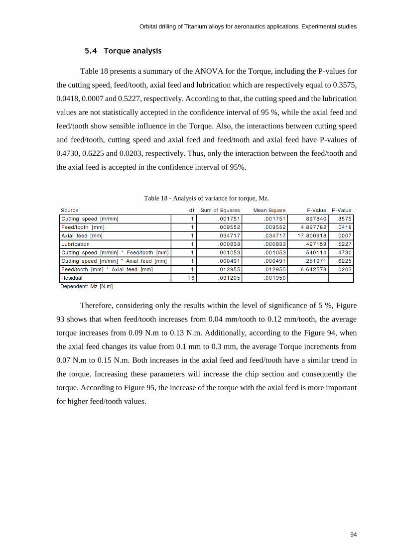
Orbital drilling of Titanium alloys for aeronautics applications. Experimental studies
94
5.4 Torque analysis
Table 18 presents a summary of the ANOVA for the Torque, including the P-values for
the cutting speed, feed/tooth, axial feed and lubrication which are respectively equal to 0.3575,
0.0418, 0.0007 and 0.5227, respectively. According to that, the cutting speed and the lubrication
values are not statistically accepted in the confidence interval of 95 %, while the axial feed and
feed/tooth show sensible influence in the Torque. Also, the interactions between cutting speed
and feed/tooth, cutting speed and axial feed and feed/tooth and axial feed have P-values of
0.4730, 0.6225 and 0.0203, respectively. Thus, only the interaction between the feed/tooth and
the axial feed is accepted in the confidence interval of 95%.
Table 18 - Analysis of variance for torque, Mz.
Therefore, considering only the results within the level of significance of 5 %, Figure
93 shows that when feed/tooth increases from 0.04 mm/tooth to 0.12 mm/tooth, the average
torque increases from 0.09 N.m to 0.13 N.m. Additionally, according to the Figure 94, when
the axial feed changes its value from 0.1 mm to 0.3 mm, the average Torque increments from
0.07 N.m to 0.15 N.m. Both increases in the axial feed and feed/tooth have a similar trend in
the torque. Increasing these parameters will increase the chip section and consequently the
torque. According to Figure 95, the increase of the torque with the axial feed is more important
for higher feed/tooth values.

Orbital drilling of Titanium alloys for aeronautics applications. Experimental studies
95
Figure 93 - Effect of the feed/tooth in the average torque, Mz.
Figure 94 - Effect of the axial feed in the average Torque, Mz.

Orbital drilling of Titanium alloys for aeronautics applications. Experimental studies
96
Figure 95 - Effect of the feed/tooth-axial feed interaction in the average Torque, Mz.
5.5 Surface Roughness analysis
The ANOVA for surface roughness results, either for Ra or Rz, were not conclusive in
terms of the influence of the factors on roughness. This lack of confidence is justified by the
residuals around 80% as can be verified by ANOVA Table 19 and Table 20. Only the cutting
speed shows statistically accepted influence on surface roughness. Consequently, observing
Figure 96 and Figure 97, one can notice that the surface roughness increases with the increase
of the cutting speed. The feed/tooth which has typically significant influence in the surface
roughness in milling operations did not reveal to have significant influence in the hole surfaces.
Also, in classic turning/milling finishing operations one should reduce the feed and increase the
cutting speed to get better surface roughness. In this study the increase in the cutting speed
resulted in higher roughness values, despite those increments in roughness being in absolute
terms very small. This seems contradictory results, but one know that drilling operations with
helical drills and finishing reaming operations are performed with distinct cutting speeds, the
lowest ones being used in reaming.

Orbital drilling of Titanium alloys for aeronautics applications. Experimental studies
97
Table 19 - Analysis of variance for Ra.
Table 20 - Analysis of variance for Rz.
Figure 96 – Effect of the cutting speed in the average surface roughness, Ra.
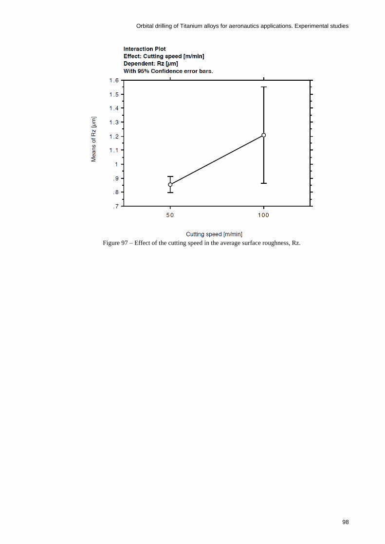
Orbital drilling of Titanium alloys for aeronautics applications. Experimental studies
98
Figure 97 – Effect of the cutting speed in the average surface roughness, Rz.

Orbital drilling of Titanium alloys for aeronautics applications. Experimental studies
99
6 Conclusions and future work
6.1 Conclusions
This chapter summarizes the main conclusions of this study. After performing the
experimental work and a preliminary results analysis, there are some conclusions to be taken
relative to the cutting loads, chip and burr formation, hole diameter variations and hole surface
roughness. Moreover, a mean and ANOVA analyses lead to additional systematic conclusions
in respect to the influence that each input cutting parameters have in the output dependent
variables of the process and the interactions among factors and their influence in the output
results. The performed analysis allowed the identification of appropriate factor levels which
lead to the best performance of the manufacturing process, in particular to the orbital drilling.
Thus, as regards the preliminary analysis of the experimental results, the following
conclusions were recognised:
The lowest axial feed per orbital revolution leads to lowest thrust forces. The
combination of the lowest axial feed with the lowest feed/tooth leads to the lowest
thrust forces. On the other hand, the highest thrust force was obtained combining
the highest axial feed with the highest feed/tooth.
The highest in-plane forces registered were under the largest feeds, either in axial
or tangential directions. On the other hand, the combination of lowest axial feed
with lowest feed/tooth leads to the smallest in-plane forces. The same conclusions
were taken for the torque value. However, it was noticed that torque value slightly
increases with increasing the cutting speed.
According to the chip formation, it was noticed that the discontinuous cut (in-plane
directions) originates shorter and thicker chip fragments, while the discontinuous
cut (axial direction) creates thinner and longer chips.
The presence of long chips is compatible with the elongation at fracture typical for
the Ti6Al4V alloy.
Either the chip length or width increase when the combination of axial feed and
feed/tooth merges, and vice-versa.
No obvious burr was created at the entrance/exit of the hole. In some cases, an
apparent burr was detected, however easily removed without any special technique.
Moreover, it was noticed a kind of incremental forming in the last stages of the hole
drilling process. Thus, in order to remove the formed cap, the axial displacement of
the tool was need in an extension of about twice of the plate thickness.

Orbital drilling of Titanium alloys for aeronautics applications. Experimental studies
100
In orbital drilling, as well as in conventional drilling, there are small discrepancies
in the diameter experimentally obtained when compared to the nominal value.
Therefore, the smallest values of the cutting parameters (cutting speed, feed/tooth,
axial feed) resulted in lower cutting forces consequently leading to the minimum
diameter deviation.
The obtained diameter varied in a range of 60 µm, highlighting the consistency of
this process. Consequently, with this information the diameter deviation can be
reduced with an interaction with the CAM software.
The surface roughness in orbital drilling process is a very important advantage
when compared with traditional drilling. In fact, the magnitude of the roughness
values was in the same range of polishing techniques which is much better than that
one may obtain with conventional drilling.
Under dry conditions in combination with the highest axial feed and lowest
feed/tooth, resulted in the biggest registered roughness values. Moreover, that
combination of parameters has the same influence in the roughness, as the opposite
parameters combination.
No signals of tool wear/damage after just performing one hole for any of the
parameters selected for the study.
Under the ANOVA and mean analysis, the following conclusions were derived:
Some uncontrollable factors (residual error) have influence in the output results. In
that order, that influence in the in-plane forces is about 11%, in the diameter is about
45 %, in the thrust force and torque about 43 %, while in the surface roughness is
about 80 %.
The increase of the axial feed from 0.1 to 0.3 increases the diameter deviation (with
respect to the nominal value of 22 mm) in 0.02 mm because the tool deflection rises
with the increase of axial feed due to the increasing cutting forces. Moreover, it can
be concluded that the axial feed influence is only relevant for lower cutting speeds
and lower feed/tooth values. Thus, one can combine the axial feed with higher
cutting speeds and higher feed/tooth and use that information to propose corrections
in the CAM software, so that the diameters get controlled within tight tolerances.
The in-plane forces tend decrease to with the increase of the cutting speed because
the temperature of the workpiece increases and therefore leads to lower forces in
any directions. On the other hand, with the increase of the feed/tooth, the in-plane
forces rise because the feeds are directly correlated to the chip thickness, and
therefore, bigger chip thickness lead to larger forces in every direction. Furthermore,

Orbital drilling of Titanium alloys for aeronautics applications. Experimental studies
101
when the axial feed rises, the material need to be cut per revolution (material
removal rate) also increases, so it was detected an increase of the in-plane forces.
Moreover, it was noticed the influence of feed/tooth is more important for lower
cutting speeds than for higher cutting speeds. Thus, the achievement of the lowest
in-plane cutting forces can be made with the selection of higher cutting speeds
combined with lower axial feed and feed/tooth.
The thrust force increases when the axial feed rises because of the fact explained in
the previous paragraph. Moreover, the use of flood coolant also increases the cutting
forces when comparing with dry machining. However, this fact is not in accordance
with the literature. The 41.42 % of residual (error) in the ANOVA may explain the
fact that some influent variations may be masked.
The average torque increases with the rise of the feed/tooth and axial feed because
of the increased chip section. Furthermore, the increase of the torque with the axial
feed is more relevant for higher feed/tooth values.
In relation to the roughness values, either Ra or Rz, the influence of factors have a
lack of confidence because of the about 80% variations attributed to unknown
factors. The feed/tooth which has typically significant influence in the surface
roughness, did not reveal to have a significant influence in the hole surfaces.
Moreover, the results show that an increase cutting speed will lead to a bigger
surface roughness, which seems contradictory with the literature.
6.2 Future work
In order to improve the better understanding of orbital drilling and the development of this
study, there are a few proposed tasks that can be performed in future activities:
Depending on the machining parameters, the cutting process differs from
experiment to experiment. In addition, in this study, even when comparing some
loading-histories among repetitions, important deviations were observed.
Therefore, some inexplicable behaviours could be observed due to uncontrollable
parameters found in Taguchi DOE. Thus, in the future, it would be essential a
repetition of the experimental work using a DOE with 3 levels adopting for
example, a different setup, in order to try to decrease the contribution of these
uncontrollable factors (e.g. gripping loads).

Orbital drilling of Titanium alloys for aeronautics applications. Experimental studies
102
A tool wear analysis to better understand the influence the cutting parameters
(cutting speed, feed/tooth, axial feed and lubrication) in the tool life and vice-versa.
This analysis can be performed counting the number of holes this process can
perform. The burr formation, tool life, diameter circularity and deviation, loads and
surface roughness should be analysed along the tool.
A FEM simulation of the orbital drilling process and a comparison with the
experimental work should be performed.
In this study, it was verified the typical Ti-6Al-4V saw tooth shape in the chip
selected from the experimental work. Consequently, it was verified that that
serrated shape occurs with a periodicity, which depends on the cutting parameters.
For future work, in order to clarify this effect, this analysis should be performed.
A comparison, in the same conditions, with the conventional drilling process in
order to verify all the advantages, orbital drilling has upon the conventional process
in relation to the lower cutting loads and tool wear, better surface e geometric
quality, increased number of holes produced, advantage in dry cutting and burr-free
holes.
A residual stress analysis in the hole surface should be performed.
Perform orbital drilling in composite or multi-layer materials, such as CFRP,
should the next step of this study.
Using orbital drilling to perform smaller holes, less than 10 mm is also of industrial
interest and should be performed in the future using solid tools.

Orbital drilling of Titanium alloys for aeronautics applications. Experimental studies
103
7 References
[1] E. O. Ezugwu and Z. M. Wang, "Titanium alloys and their machinability—a review,"
Journal of Materials Processing Technology, vol. 68, pp. 262-274, 1997/08/15 1997.
[2] V. Fernandes. (2016, 28-11-2016). Titânio e suas ligas. Available:
http://engenheirodemateriais.com.br/tag/metalurgia-do-titanio/
[3] Computational Thermodynamics. (2016, 25-11-2016). Titanium-Aluminum (Ti-Al)
Phase Diagram. Available: http://www.calphad.com/titanium-aluminum.html
[4] I. Sacristan, A. Garay, E. Hormaetxe, J. Aperribay, and P. J. Arrazola, "Influence of
oxygen content on the machinability of Ti-6Al-4V alloy," The International Journal of
Advanced Manufacturing Technology, vol. 86, pp. 2989-3005, 2016.
[5] KENNAMETAL. (2016, 28-11-2016). Titanium Machining Guide. Available:
http://www.kennametal.com/content/dam/kennametal/kennametal/common/Industry%
20Solutions/Aerospace/Titanium%20Machining/Titanium_material_machining_guide
_Aerospace.pdf
[6] L. N. López de lacalle, J. Pérez, J. I. Llorente, and J. A. Sánchez, "Advanced cutting
conditions for the milling of aeronautical alloys," vol. 100, ed, 2000, p. 1.
[7] X. Yang and C. Richard Liu, "MACHINING TITANIUM AND ITS ALLOYS,"
Machining Science and Technology, vol. 3, pp. 107-139, 1999/01/01 1999.
[8] (2016, 15-12-2016). Titanium: applications and uses-Metalpedia. Available:
http://metalpedia.asianmetal.com/metal/titanium/application.shtml
[9] S. I. Jaffery and P. T. Mativenga, "Assessment of the machinability of Ti-6Al-4V
alloy using the wear map approach," vol. 40, ed, 2009, p. 687.
[10] A. Pramanik, "Problems and solutions in machining of titanium alloys," International
Journal of Advanced Manufacturing Technology, vol. 70, pp. 919-928, 2014.
[11] S. Coromant, "Workpiece material groups," 2016.
[12] E. Ezugwu, J. Bonney, and Y. Yamane, "An overview of the machinability of
aeroengine alloys," Journal of materials processing technology, vol. 134, pp. 233-253,
2003.
[13] E. Almond, "Towards improved tests based on fundamental properties," in
Proceedings of the International Conference on Improved Performance of Tool
Materials, The National Laboratory and the Metals Society, Teddington, Middlesex,
1981, pp. 161-9.

Orbital drilling of Titanium alloys for aeronautics applications. Experimental studies
104
[14] S. Coromant. (2016, 14-11-2016). ISO S HRSA e Titânio. Available:
http://www.sandvik.coromant.com/pt-
pt/knowledge/materials/workpiece_materials/iso_s_hrsa_titanium/pages/default.aspx
[15] S. Coromant, "Cutting tool materials," 2017.
[16] S. Coromant, "Manual técnico de usinagem, torneamento, fresamento, furação,
mandrilamento e sistemas de fixação," SUCURSAL PORTUGAL, 2005.
[17] S. Coromant. (2017, 23-10-2016). Application overview. Available:
http://www.sandvik.coromant.com/en-
gb/knowledge/milling/application_overview/pages/default.aspx
[18] Keo. (2016, 13-11-2016). Solutions – KEO Cutters. Available:
http://www.keocutters.com/solutions/
[19] C. Liu, G. Wang, and M. S. Dargusch, "Mechanics and dynamics of helical milling
operations," Strojniški vestnik-Journal of Mechanical Engineering, vol. 60, pp. 716-
724, 2014.
[20] R. Iyer, P. Koshy, and E. Ng, "Helical milling: An enabling technology for hard
machining precision holes in AISI D2 tool steel," International Journal of Machine
Tools and Manufacture, vol. 47, pp. 205-210, 2// 2007.
[21] X. D. Qin, X. T. Sun, Q. Wang, S. M. Chen, and H. Li, "Comparative study on helical
milling and drilling of Ti-6Al-4V," in Key Engineering Materials vol. 499, ed, 2012,
pp. 200-204.
[22] G. He, H. Li, Y. Jiang, X. Qin, X. Zhang, and Y. Guan, "Helical milling of CFRP/Ti-
6Al-4V stacks with varying machining parameters," Transactions of Tianjin
University, vol. 21, pp. 56-63, 2015.
[23] E. Whinnem, G. Lipczynski, and I. Eriksson, "Development of Orbital Drilling for the
Boeing 787," SAE Int. J. Aerosp., vol. 1, pp. 811-816, 2008.
[24] E. Brinksmeier, S. Fangmann, and A. Walter, "High Speed-Machining of Multilayer
Composite Materials by Orbital Drilling," in Sixth International Conference of High
Speed Machining, 2007, pp. 21-22.
[25] M. C. Shaw, Metal cutting principles vol. 2: Oxford university press New York, 2005.
[26] H. K. Toenshoff and B. Denkena, "Basics of cutting and abrasive processes," 2013.
[27] B. Denkena, D. Boehnke, and J. H. Dege, "Helical milling of CFRP–titanium layer
compounds," CIRP Journal of Manufacturing Science and Technology, vol. 1, pp. 64-
69, // 2008.
[28] X. Qin, L. Gui, H. Li, B. Rong, D. Wang, H. Zhang, et al., "Feasibility Study on the
Minimum Quantity Lubrication in High-Speed Helical Milling of Ti-6Al-4V," Journal
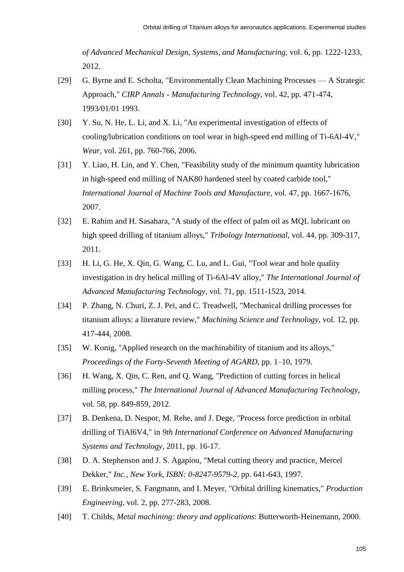
Orbital drilling of Titanium alloys for aeronautics applications. Experimental studies
105
of Advanced Mechanical Design, Systems, and Manufacturing, vol. 6, pp. 1222-1233,
2012.
[29] G. Byrne and E. Scholta, "Environmentally Clean Machining Processes — A Strategic
Approach," CIRP Annals - Manufacturing Technology, vol. 42, pp. 471-474,
1993/01/01 1993.
[30] Y. Su, N. He, L. Li, and X. Li, "An experimental investigation of effects of
cooling/lubrication conditions on tool wear in high-speed end milling of Ti-6Al-4V,"
Wear, vol. 261, pp. 760-766, 2006.
[31] Y. Liao, H. Lin, and Y. Chen, "Feasibility study of the minimum quantity lubrication
in high-speed end milling of NAK80 hardened steel by coated carbide tool,"
International Journal of Machine Tools and Manufacture, vol. 47, pp. 1667-1676,
2007.
[32] E. Rahim and H. Sasahara, "A study of the effect of palm oil as MQL lubricant on
high speed drilling of titanium alloys," Tribology International, vol. 44, pp. 309-317,
2011.
[33] H. Li, G. He, X. Qin, G. Wang, C. Lu, and L. Gui, "Tool wear and hole quality
investigation in dry helical milling of Ti-6Al-4V alloy," The International Journal of
Advanced Manufacturing Technology, vol. 71, pp. 1511-1523, 2014.
[34] P. Zhang, N. Churi, Z. J. Pei, and C. Treadwell, "Mechanical drilling processes for
titanium alloys: a literature review," Machining Science and Technology, vol. 12, pp.
417-444, 2008.
[35] W. Konig, "Applied research on the machinability of titanium and its alloys,"
Proceedings of the Forty-Seventh Meeting of AGARD, pp. 1–10, 1979.
[36] H. Wang, X. Qin, C. Ren, and Q. Wang, "Prediction of cutting forces in helical
milling process," The International Journal of Advanced Manufacturing Technology,
vol. 58, pp. 849-859, 2012.
[37] B. Denkena, D. Nespor, M. Rehe, and J. Dege, "Process force prediction in orbital
drilling of TiAl6V4," in 9th International Conference on Advanced Manufacturing
Systems and Technology, 2011, pp. 16-17.
[38] D. A. Stephenson and J. S. Agapiou, "Metal cutting theory and practice, Mercel
Dekker," Inc., New York, ISBN: 0-8247-9579-2, pp. 641-643, 1997.
[39] E. Brinksmeier, S. Fangmann, and I. Meyer, "Orbital drilling kinematics," Production
Engineering, vol. 2, pp. 277-283, 2008.
[40] T. Childs, Metal machining: theory and applications: Butterworth-Heinemann, 2000.

Orbital drilling of Titanium alloys for aeronautics applications. Experimental studies
106
[41] S. Coromant. (2017, 13-01-2017). Tool wear. Available:
http://www.sandvik.coromant.com/en-
gb/knowledge/milling/troubleshooting/tool_wear/pages/default.aspx
[42] (2016, 9-11-2016). Win Tech. Available: http://wintech-
eg.com/machine_dmg_DMUeVo_products.php
[43] C. Hysol. (2017, 29-01-2017). Castrol Hysol XF. Available:
https://getlubricants.com/tds/castrol-hysol-xf
[44] S. Coromant. (2016). r390-11 t3 08m-pm 1130. Available:
http://www.sandvik.coromant.com/en-gb/products/pages/productdetails.aspx?c=r390-
11+t3+08m-pm+1130
[45] S. Coromant. (2016, 15-10-2016). Circular ramping. Available:
http://www.sandvik.coromant.com/en-
gb/knowledge/milling/application_overview/holes_and_cavities/circular_ramping/pag
es/default.aspx
[46] Olympus. (2017, 18-01-2017). Parametros de rugosidade (2D) | Olympus IMS.
Available: http://www.olympus-
ims.com/pt/knowledge/metrology/roughness/2d_parameter/
[47] G. Taguchi and S. Konishi, Orthogonal arrays and linear graphs: tools for quality
engineering: American Supplier Institute, 1987.
[48] S. Athreya and Y. Venkatesh, "Application of taguchi method for optimization of
process parameters in improving the surface roughness of lathe facing operation," Int.
Refereed J. Eng. Sci, vol. 1, pp. 13-19, 2012.
[49] T. S. Test. (2016, 28-12-2016). Study Interactions Using The Taguchi Method.
Available: http://www.taguchisplittest.com/user-contributions/study-interactions-
using-the-taguchi-method/
[50] A. Poutord, F. Rossi, G. Poulachon, and G. Abrivard, "Study of the local forces along
a drill edge-comparison of two methodologies," in Congrès Français de Mécanique
(21; 2013; Bordeaux), 2013, pp. 1-6.
[51] S. Sun, M. Brandt, and M. S. Dargusch, "Characteristics of cutting forces and chip
formation in machining of titanium alloys," International Journal of Machine Tools
and Manufacture, vol. 49, pp. 561-568, 2009.
[52] R. Neugebauer, U. Ben-Hanan, S. Ihlenfeldt, M. Wabner, and A. Stoll, "Acoustic
emission as a tool for identifying drill position in fiber-reinforced plastic and
aluminum stacks," International Journal of Machine Tools and Manufacture, vol. 57,
pp. 20-26, 2012.

Orbital drilling of Titanium alloys for aeronautics applications. Experimental studies
107
[53] Wikimedia. (2008, 18-01-2017). File:Surface Finish Tolerances In Manfacturing.png
- Wikimedia Commons. Available:
https://commons.wikimedia.org/wiki/File:Surface_Finish_Tolerances_In_Manfacturin
g.png

Orbital drilling of Titanium alloys for aeronautics applications. Experimental studies
108

Orbital drilling of Titanium alloys for aeronautics applications. Experimental studies
109
8 Annex A – Experimental results
In this chapter, one can observe all the graphs in respect to the repetitions of the
experimental work, which can be seen from Figure A1 to Figure A30. Moreover, from Table
A1 to Table A7, one can see all the resulted output data from the experimental work, which was
used in the ANOVA and means analysis.
Figure A1- Cutting forces of the experimental test 2.1 (vc: 50 m/min; st: 0.04 mm/tooth; a: 0.1 mm/rot and
Lubrication type: Dry)
Figure A2- Torque of the experimental test 2.1 (vc: 50 m/min; st: 0.04 mm/tooth; a: 0,1 mm/rot and Lubrication
type: Dry)

Orbital drilling of Titanium alloys for aeronautics applications. Experimental studies
110
Figure A3 - Cutting forces of the experimental test 3.1 (vc: 50 m/min; st: 0.04 mm/tooth; a: 0.1 mm/rot and
Lubrication type: Dry)
Figure A4 - Torque of the experimental test 3.1 (vc: 50 m/min; st: 0.04 mm/tooth; a: 0,1 mm/rot and Lubrication
type: Dry)

Orbital drilling of Titanium alloys for aeronautics applications. Experimental studies
111
Figure A5 - Cutting forces of the experimental test 2.2 (vc: 50 m/min; st: 0.04 mm/tooth; a: 0.3 mm/rot and
Lubrication type: Wet)
Figure A6 - Torque of the experimental test 2.2 (vc: 50 m/min; st: 0.04 mm/tooth; a: 0.3 mm/rot and Lubrication
type: Wet)

Orbital drilling of Titanium alloys for aeronautics applications. Experimental studies
112
Figure A7 - Cutting forces of the experimental test 3.2 (vc: 50 m/min; st: 0.04 mm/tooth; a: 0.3 mm/rot and
Lubrication type: Wet)
Figure A8 - Torque of the experimental test 3.2 (vc: 50 m/min; st: 0.04 mm/tooth; a: 0.3 mm/rot and Lubrication
type: Wet)

Orbital drilling of Titanium alloys for aeronautics applications. Experimental studies
113
Figure A9 - Cutting forces of the experimental test 2.3 (vc: 50 m/min; st: 0.12 mm/tooth; a: 0.1 mm/rot and
Lubrication type: Wet)
Figure A10 - Torque of the experimental test 2.3 (vc: 50 m/min; st: 0.12 mm/tooth; a: 0,1 mm/rot and Lubrication
type: Wet)

Orbital drilling of Titanium alloys for aeronautics applications. Experimental studies
114
Figure A11 - Cutting forces of the experimental test 3.3 (vc: 50 m/min; st: 0.12 mm/tooth; a: 0.1 mm/rot and
Lubrication type: Wet)
Figure A12 - Torque of the experimental test 3.3 (vc: 50 m/min; st: 0.12 mm/tooth; a: 0,1 mm/rot and Lubrication
type: Wet)
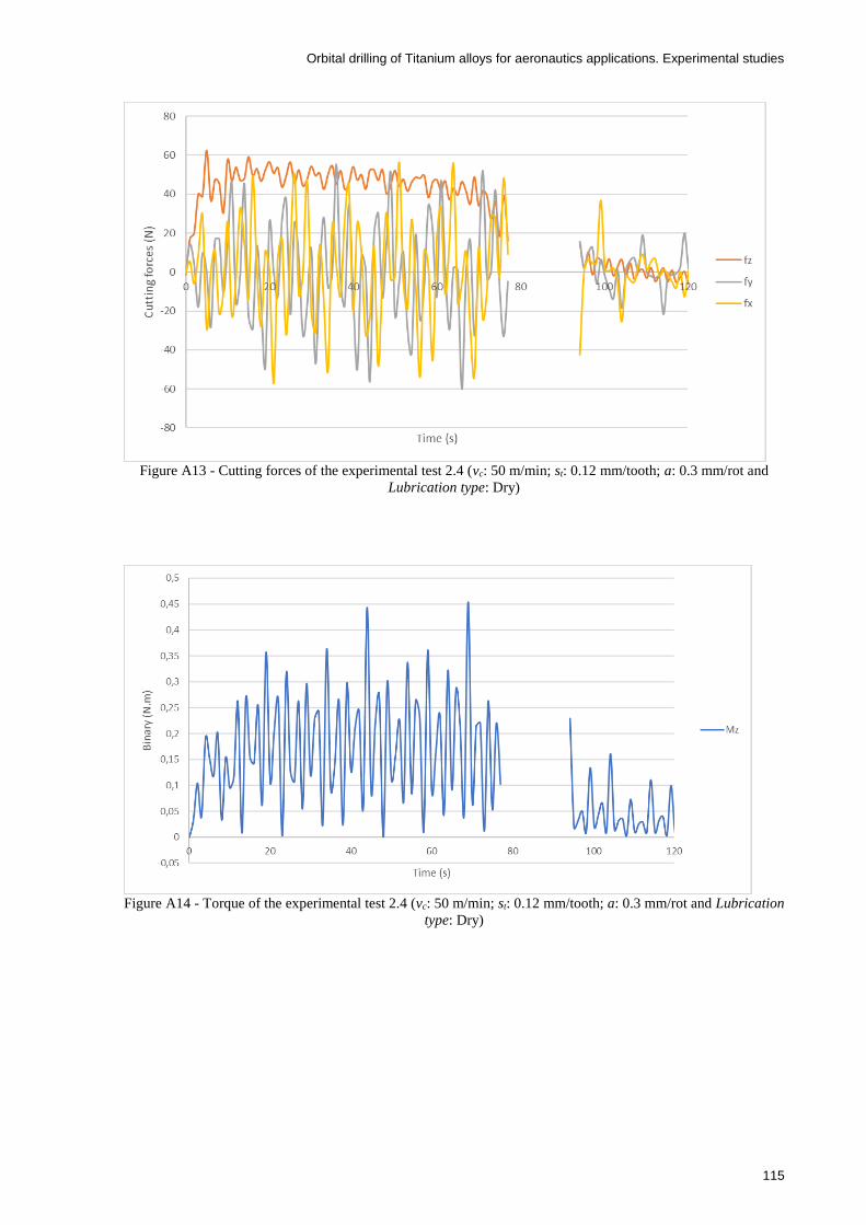
Orbital drilling of Titanium alloys for aeronautics applications. Experimental studies
115
Figure A13 - Cutting forces of the experimental test 2.4 (vc: 50 m/min; st: 0.12 mm/tooth; a: 0.3 mm/rot and
Lubrication type: Dry)
Figure A14 - Torque of the experimental test 2.4 (vc: 50 m/min; st: 0.12 mm/tooth; a: 0.3 mm/rot and Lubrication
type: Dry)
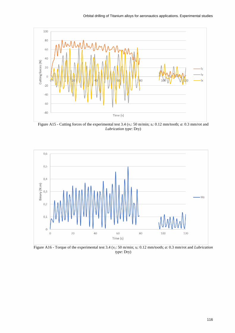
Orbital drilling of Titanium alloys for aeronautics applications. Experimental studies
116
Figure A15 - Cutting forces of the experimental test 3.4 (vc: 50 m/min; st: 0.12 mm/tooth; a: 0.3 mm/rot and
Lubrication type: Dry)
Figure A16 - Torque of the experimental test 3.4 (vc: 50 m/min; st: 0.12 mm/tooth; a: 0.3 mm/rot and Lubrication
type: Dry)

Orbital drilling of Titanium alloys for aeronautics applications. Experimental studies
117
Figure A17 - Cutting forces of the experimental test 2.5 (vc: 100 m/min; st: 0.04 mm/tooth; a: 0.1 mm/rot and
Lubrication type: Wet)
Figure A18 - Torque of the experimental test 2.5 (vc: 100 m/min; st: 0.04 mm/tooth; a: 0.1 mm/rot and
Lubrication type: Wet)
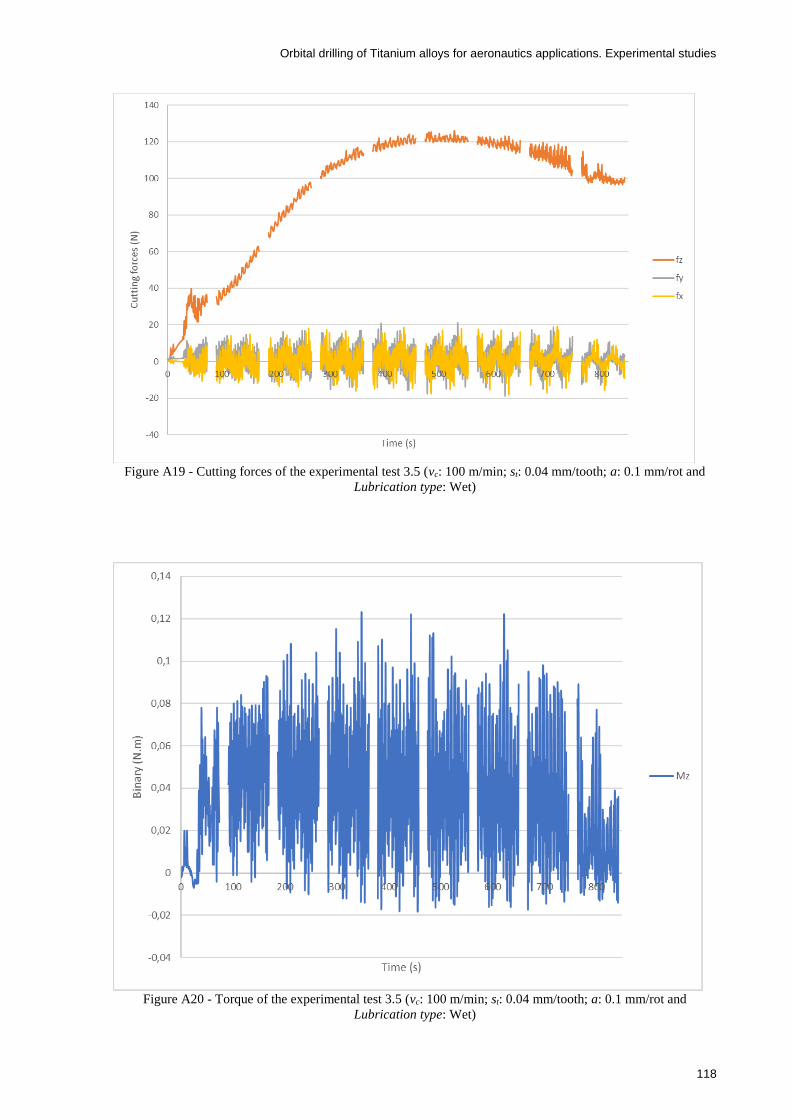
Orbital drilling of Titanium alloys for aeronautics applications. Experimental studies
118
Figure A19 - Cutting forces of the experimental test 3.5 (vc: 100 m/min; st: 0.04 mm/tooth; a: 0.1 mm/rot and
Lubrication type: Wet)
Figure A20 - Torque of the experimental test 3.5 (vc: 100 m/min; st: 0.04 mm/tooth; a: 0.1 mm/rot and
Lubrication type: Wet)

Orbital drilling of Titanium alloys for aeronautics applications. Experimental studies
119
Figure A21 - Cutting forces of the experimental test 2.6 (vc: 100 m/min; st: 0.04 mm/tooth; a: 0.3 mm/rot and
Lubrication type: Dry)
Figure A22 - Torque of the experimental test 2.6 (vc: 100 m/min; st: 0.04 mm/tooth; a: 0.3 mm/rot and
Lubrication type: Dry)

Orbital drilling of Titanium alloys for aeronautics applications. Experimental studies
120
Figure A23 - Cutting forces of the experimental test 3.6 (vc: 100 m/min; st: 0.04 mm/tooth; a: 0.3 mm/rot and
Lubrication type: Dry)
Figure A24 - Torque of the experimental test 3.6 (vc: 100 m/min; st: 0.04 mm/tooth; a: 0.3 mm/rot and
Lubrication type: Dry)

Orbital drilling of Titanium alloys for aeronautics applications. Experimental studies
121
Figure A25 - Cutting forces of the experimental test 2.7 (vc: 100 m/min; st: 0.12 mm/tooth; a: 0.1 mm/rot and
Lubrication type: Dry)
Figure A26 - Torque of the experimental test 2.7 (vc: 100 m/min; st: 0.12 mm/tooth; a: 0.1 mm/rot and
Lubrication type: Dry)
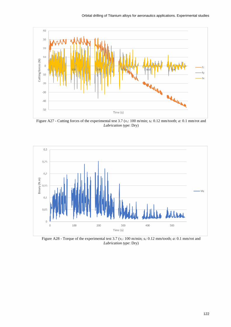
Orbital drilling of Titanium alloys for aeronautics applications. Experimental studies
122
Figure A27 - Cutting forces of the experimental test 3.7 (vc: 100 m/min; st: 0.12 mm/tooth; a: 0.1 mm/rot and
Lubrication type: Dry)
Figure A28 - Torque of the experimental test 3.7 (vc: 100 m/min; st: 0.12 mm/tooth; a: 0.1 mm/rot and
Lubrication type: Dry)

Orbital drilling of Titanium alloys for aeronautics applications. Experimental studies
123
Figure A29 - Cutting forces of the experimental test 3.8 (vc: 100 m/min; st: 0.12 mm/tooth; a: 0.3 mm/rot and
Lubrication type: Wet)
Figure A30 - Torque of the experimental test 3.8 (vc: 100 m/min; st: 0.12 mm/tooth; a: 0.3 mm/rot and
Lubrication type: Wet)

Orbital drilling of Titanium alloys for aeronautics applications. Experimental studies
124
Table A1 - Diameter results
Diameter (mm)
Repetitions
Test vc st a Lubrication #1 #2 #3
1 50 0.04 0.1 dry 21.89 21.89 21.90
2 50 0.04 0.3 wet 21.80 21.83 21.86
3 50 0.12 0.1 wet 21.85 21.87 21.84
4 50 0.12 0.3 dry 21.84 21.86 21.82
5 100 0.04 0.1 wet 21.84 21.85 21.85
6 100 0.04 0.3 dry 21.82 21.84 21.84
7 100 0.12 0.1 dry 21.86 21.83 21.85
8 100 0.12 0.3 wet 21.83 21.88 21.85
Table A2 - Surface roughness Ra results
Ra (µm)
Repetitions Test vc st a Lubrication #1 #2 #3
1 50 0.04 0.1 dry * 0.157 0.120 2 50 0.04 0.3 wet 0.133 0.157 0.173 3 50 0.12 0.1 wet 0.140 0.153 0.150 4 50 0.12 0.3 dry 0.133 0.183 0.153 5 100 0.04 0.1 wet 0.120 0.130 0.177 6 100 0.04 0.3 dry 0.347 0.306 0.137 7 100 0.12 0.1 dry 0.327 0.350 0.153 8 100 0.12 0.3 wet 0.143 0.406 0.075
*In this experimental test, the tool could not machine a through hole, so an average value from the repetition #2 and #3 was used in ANOVA
Table A3 - Surface roughness Rz results
Rz (µm)
Repetitions Test vc st a Lubrication #1 #2 #3
1 50 0.04 0.1 dry * 0.927 0.743 2 50 0.04 0.3 wet 0.800 0.890 1.020 3 50 0.12 0.1 wet 0.793 0.830 0.817 4 50 0.12 0.3 dry 0.753 1.000 0.843 5 100 0.04 0.1 wet 0.760 0.803 1.310 6 100 0.04 0.3 dry 1.853 1.590 0.723 7 100 0.12 0.1 dry 1.747 1.893 0.813 8 100 0.12 0.3 wet 0.790 1.780 0.415
*In this experimental test, the tool could not machine a through hole, so an average value from the repetition #2 and #3 was used.

Orbital drilling of Titanium alloys for aeronautics applications. Experimental studies
125
Table A4 - Maximum of the cutting force Fz -results
Fz_max (N)
Repetitions
Test vc st a Lubrication #1 #2 #3
1 50 0.04 0.1 dry 35.0 25.5 25.2
2 50 0.04 0.3 wet 61.2 66.5 67.9
3 50 0.12 0.1 wet 30.8 59.6 47.4
4 50 0.12 0.3 dry 52.9 49.5 67.4
5 100 0.04 0.1 wet 36.6 91.3 30.3
6 100 0.04 0.3 dry 52.2 41.3 43.7
7 100 0.12 0.1 dry 24.6 29.6 26.8
8 100 0.12 0.3 wet 77.4 * 74.1
*This test had not shown reliable results. Thus, an average value from the repetition #1 and #3 was used.
Table A5 - Maximum of the Torque Mz -results
Mz_max (N.m)
Repetitions
Test vc st a Lubrication #1 #2 #3
1 50 0.04 0.1 dry 0.052 0.053 0.048
2 50 0.04 0.3 wet 0.123 0.098 0.084
3 50 0.12 0.1 wet 0.054 0.080 0.074
4 50 0.12 0.3 dry 0.192 0.179 0.196
5 100 0.04 0.1 wet 0.051 0.225 0.031
6 100 0.04 0.3 dry 0.175 0.077 0.080
7 100 0.12 0.1 dry 0.048 0.082 0.082
8 100 0.12 0.3 wet 0.193 * 0.198
*This test had not shown reliable results. Thus, an average value from the repetition #1 and #3 was used.
Table A6 - Maximum of the cutting force Fy -results
Fy_max (N)
Repetitions
Test vc st a Lubrication #1 #2 #3
1 50 0.04 0.1 dry 14.86 15.28 15.12
2 50 0.04 0.3 wet 41.95 33.24 35.76
3 50 0.12 0.1 wet 17.96 26.60 28.32
4 50 0.12 0.3 dry 72.22 67.56 69.36
5 100 0.04 0.1 wet 6.69 16.28 13.64
6 100 0.04 0.3 dry 40.88 15.28 18.64
7 100 0.12 0.1 dry 7.64 15.68 22.60
8 100 0.12 0.3 wet 43.00 * 45.32
*This test had not shown reliable results. Thus, an average value from the repetition #1 and #3 was used.

Orbital drilling of Titanium alloys for aeronautics applications. Experimental studies
126
Table A7 - Maximum of the cutting force Fx -results
Fx_max (N)
Repetitions
Test vc st a Lubrication #1 #2 #3
1 50 0.04 0.1 dry 14.57 15.08 14.84
2 50 0.04 0.3 wet 42.90 34.24 35.20
3 50 0.12 0.1 wet 20.68 24.28 26.16
4 50 0.12 0.3 dry 74.68 66.84 71.52
5 100 0.04 0.1 wet 6.13 19.84 10.72
6 100 0.04 0.3 dry 41.13 19.36 19.12
7 100 0.12 0.1 dry 7.40 16.88 23.36
8 100 0.12 0.3 wet 43.12 * 45.68
*This test had not shown reliable results. Thus, an average value from the repetition #1 and #3 was used.

Orbital drilling of Titanium alloys for aeronautics applications. Experimental studies
127
9 Annex B – ANOVA and mean analysis results – Means graphs
In this annex, one can observe the graphs, from Figure B1 to Figure B26, related to the
mean analysis of the results which are not accepted in the confidence interval of 95 %,
calculated in the analysis ANOVA.
Figure B1 - Effect of the cutting speed in the hole diameter.
Figure B2 - Effect of the feed/tooth in the hole diameter.

Orbital drilling of Titanium alloys for aeronautics applications. Experimental studies
128
Figure B3 - Effect of the Lubrication in the hole diameter with the respective means table.
Figure B4 - Effect of the interaction between the cutting speed-feed/tooth in the hole diameter.
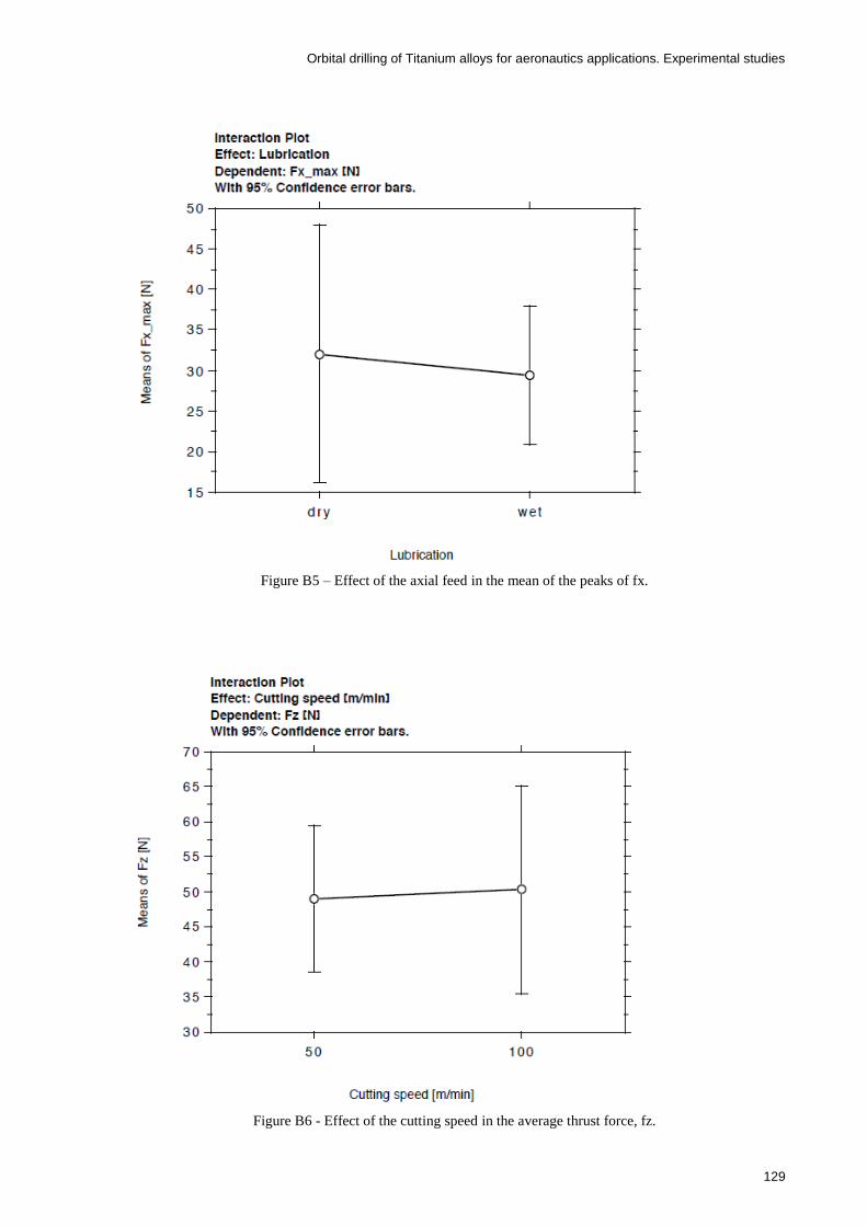
Orbital drilling of Titanium alloys for aeronautics applications. Experimental studies
129
Figure B5 – Effect of the axial feed in the mean of the peaks of fx.
Figure B6 - Effect of the cutting speed in the average thrust force, fz.

Orbital drilling of Titanium alloys for aeronautics applications. Experimental studies
130
Figure B7 - Effect of the feed/tooth in the average thrust force, fz.
Figure B8 – Effect of the cutting speed-feed/tooth interaction in the average thrust force, fz.

Orbital drilling of Titanium alloys for aeronautics applications. Experimental studies
131
Figure B9 – Effect of the cutting speed-axial feed interaction in the average thrust force, fz.
Figure B10 - Effect of the feed/tooth-axial feed interaction in the average thrust force, fz.
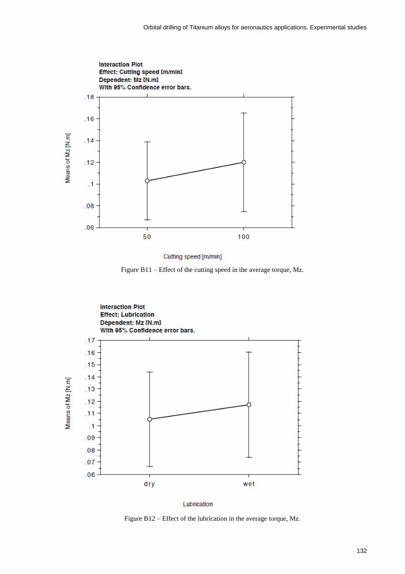
Orbital drilling of Titanium alloys for aeronautics applications. Experimental studies
132
Figure B11 – Effect of the cutting speed in the average torque, Mz.
Figure B12 – Effect of the lubrication in the average torque, Mz.

Orbital drilling of Titanium alloys for aeronautics applications. Experimental studies
133
Figure B13 - Effect of the cutting speed-feed/tooth interaction in the average torque, Mz.
Figure B14 - Effect of the cutting speed-axial feed interaction in the average torque, Mz.

Orbital drilling of Titanium alloys for aeronautics applications. Experimental studies
134
Figure B15 – Effect of the feed/tooth in the average surface roughness, Ra.
Figure B16 - Effect of the feed/tooth in the average surface roughness, Ra.

Orbital drilling of Titanium alloys for aeronautics applications. Experimental studies
135
Figure B17 – Effect of the Lubrication in the average surface roughness, Ra.
Figure B18 - Effect of the cutting speed-feed/tooth interaction in the average roughness, Ra.

Orbital drilling of Titanium alloys for aeronautics applications. Experimental studies
136
Figure B19 - Effect of the cutting speed-axial feed interaction in the average roughness, Ra.
Figure B20 - Effect of the feed/tooth-axial feed interaction in the average roughness, Ra.

Orbital drilling of Titanium alloys for aeronautics applications. Experimental studies
137
Figure B21 - Effect of the feed/tooth in the average surface roughness, Rz.
Figure B22 - Effect of the axial feed in the average surface roughness, Rz.

Orbital drilling of Titanium alloys for aeronautics applications. Experimental studies
138
Figure B23 - Effect of the Lubrication in the average surface roughness, Rz.
Figure B24 - Effect of the cutting speed-feed/tooth interaction in the average roughness, Rz.

Orbital drilling of Titanium alloys for aeronautics applications. Experimental studies
139
Figure B25 - Effect of the cutting speed-axial feed interaction in the average roughness, Rz.
Figure B26 - Effect of the feed/tooth-axial feed interaction in the average roughness, Rz.

Orbital drilling of Titanium alloys for aeronautics applications. Experimental studies
140

Orbital drilling of Titanium alloys for aeronautics applications. Experimental studies
141
10 Annex C - ANOVA and mean analysis results – Means tables
In this annex, from Table C1 to Table C42, are presented the means tables which include
all the relevant data related to the means graphs that can be observed either in chapter 5 or
Annex B.
Table C1 – Means table of the cutting speed effect on the dependent diameter.
Table C2 - Means table of the feed/tooth effect on the dependent diameter.
Table C3 - Means table of the axial feed effect on the dependent diameter.
Table C4 - Means table of the lubrication effect on the dependent diameter.

Orbital drilling of Titanium alloys for aeronautics applications. Experimental studies
142
Table C5 - Means table of the interaction cutting speed-feed/tooth effect on the dependent diameter.
Table C6 - Means table of the interaction cutting speed-axial feed effect on the dependent diameter.
Table C7 - Means table of the interaction feed/tooth-axial feed effect on the dependent diameter.
Table C8 - Means table of the cutting speed effect on the in-plane force, fx.
Table C9 - Means table of the feed/tooth effect on the in-plane force, fx.

Orbital drilling of Titanium alloys for aeronautics applications. Experimental studies
143
Table C10 - Means table of the axial feed effect on the in-plane force, fx.
Table C11 - Means table of the lubrication effect on the in-plane force, fx.
Table C12 - Means table of the interaction cutting speed-feed/tooth effect on the in-plane force, fx.
Table C13 - Means table of the interaction cutting speed-axial feed effect on the in-plane force, fx.
Table C14 - Means table of the interaction feed/tooth-axial feed effect on the in-plane force, fx.

Orbital drilling of Titanium alloys for aeronautics applications. Experimental studies
144
Table C15 - Means table of the cutting speed effect on the thrust force, fz.
Table C16 - Means table of the feed/tooth effect on the thrust force, fz.
Table C17 - Means table of the axial feed effect on the thrust force, fz.
Table C18 - Means table of the lubrication effect on the thrust force, fz.
Table C19 - Means table of the interaction cutting speed-feed/tooth effect on the thrust force, fz.

Orbital drilling of Titanium alloys for aeronautics applications. Experimental studies
145
Table C20 - Means table of the interaction cutting speed-axial feed effect on the thrust force, fz.
Table C21 - Means table of the interaction feed/tooth-axial feed effect on the thrust force, fz.
Table C22 - Means table of the cutting speed effect on the torque, Mz.
Table C23 - Means table of the feed/tooth effect on the torque, Mz.
Table C24 - Means table of the axial feed effect on the torque, Mz.
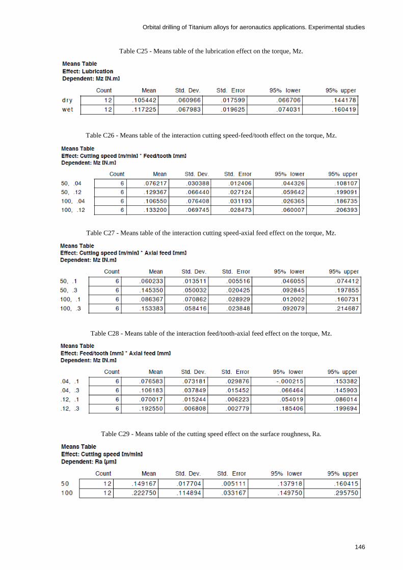
Orbital drilling of Titanium alloys for aeronautics applications. Experimental studies
146
Table C25 - Means table of the lubrication effect on the torque, Mz.
Table C26 - Means table of the interaction cutting speed-feed/tooth effect on the torque, Mz.
Table C27 - Means table of the interaction cutting speed-axial feed effect on the torque, Mz.
Table C28 - Means table of the interaction feed/tooth-axial feed effect on the torque, Mz.
Table C29 - Means table of the cutting speed effect on the surface roughness, Ra.

Orbital drilling of Titanium alloys for aeronautics applications. Experimental studies
147
Table C30 - Means table of the feed/tooth effect on the surface roughness, Ra.
Table C31 - Means table of the axial feed effect on the surface roughness, Ra.
Table C32 - Means table of the lubrication effect on the surface roughness, Ra.
Table C33 - Means table of the interaction cutting speed-feed/tooth effect on the surface roughness, Ra.

Orbital drilling of Titanium alloys for aeronautics applications. Experimental studies
148
Table C34 - Means table of the interaction cutting speed-axial feed effect on the surface roughness, Ra.
Table C35 - Means table of the interaction feed/tooth-axial feed effect on the surface roughness, Ra.
Table C36 - Means table of the cutting speed effect on the surface roughness, Rz.
Table C37 - Means table of the feed/tooth effect on the surface roughness, Rz.
Table C38 - Means table of the axial feed effect on the surface roughness, Rz.
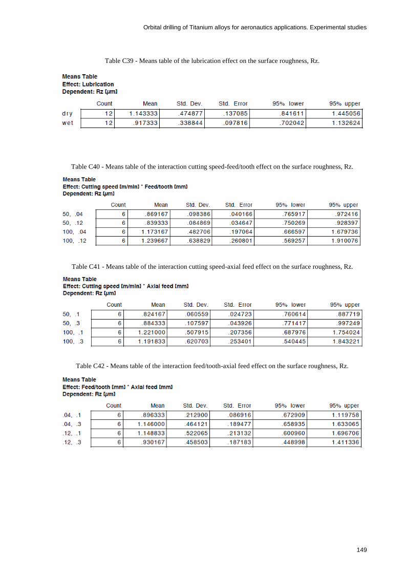
Orbital drilling of Titanium alloys for aeronautics applications. Experimental studies
149
Table C39 - Means table of the lubrication effect on the surface roughness, Rz.
Table C40 - Means table of the interaction cutting speed-feed/tooth effect on the surface roughness, Rz.
Table C41 - Means table of the interaction cutting speed-axial feed effect on the surface roughness, Rz.
Table C42 - Means table of the interaction feed/tooth-axial feed effect on the surface roughness, Rz.