organic solar cells - iit kanpur · pdf filephysics and circuit model of organic solar cells...
TRANSCRIPT

1
S. Sundar Kumar Iyer
Samtel Centre for Display Technologies
Organic Solar Cells

2
Outline
� Motivation
■ Solar cells
■ Organic solar cells
� Background
■ Working of organic solar cell
■ Fabrication steps
� Research at IIT K
■ Molecule, device, circuit and system level
3
Clean Energy Supply Needed for Quality of Life
� Fossil and nuclear fuels are costly
■ If we include the environmental cost
� The sun shines on everyone
■ Ideal for distributed power generation and remote locations
� Tap solar energy directly
■ Ideal for distributed power generation
■ More environmentally friendly

4
Annual Mean Global Irradiance
On a horizontal plane at the surface of the earth W m-2 averaged over 24 h
With 10% efficient solar cell area of solar cell needed in 2004
India 60 km × 60 km (0.12% area) World need: 350 km × 350 km
5
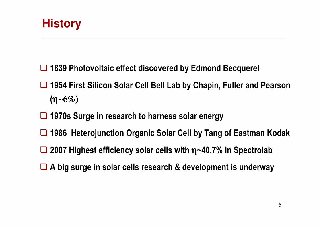
History
� 1839 Photovoltaic effect discovered by Edmond Becquerel
� 1954 First Silicon Solar Cell Bell Lab by Chapin, Fuller and Pearson
(η∼6%)η∼6%)η∼6%)η∼6%)
� 1970s Surge in research to harness solar energy
� 1986 Heterojunction Organic Solar Cell by Tang of Eastman Kodak
� 2007 Highest efficiency solar cells with ηηηη~40.7% in Spectrolab
� A big surge in solar cells research & development is underway
6
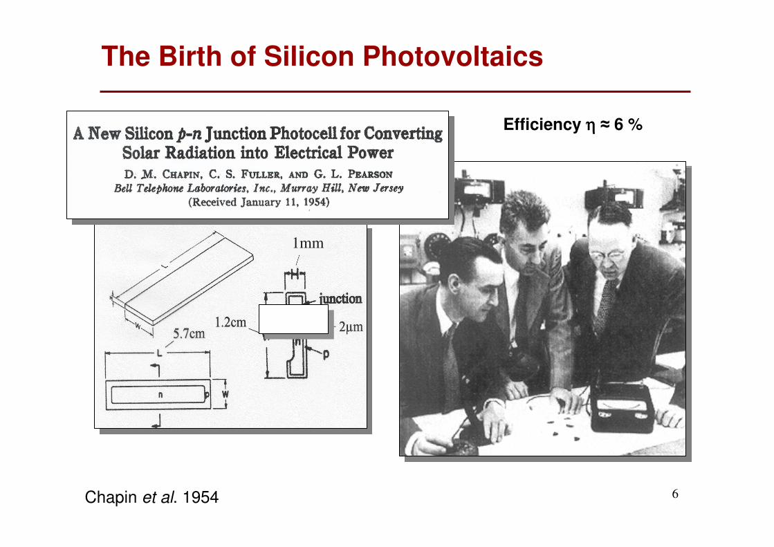
1mm
Efficiency ηηηη ≈ 6 %
Chapin et al. 1954
The Birth of Silicon Photovoltaics

7
Space Applications
www.spacetoday.org
marsrovers.nasa.gov
Photovoltaics are the mainstay

8
Remote Locations
www.dacres.org
web.worldbank.orgsummitclimb.com
Photovoltaicsare attractive

9
Consumer Electronics

10
Grid Supply
www.e2tac.org
www.sun-consult.de
Need to make photovoltaicsattractive in the marketplace

11
Solar Energy Usage and Pricing
n/a2%Consumer Indoor
2-5 times59%Grid Connected
0.2-0.8 times22%Remote Habitation
0.1-0.5 times17%Remote Industrial
Solar Price/Competing
Energy source
Solar markets
(average of last 5 years)
http://www.solarbuzz.com/StatsCosts.htm (2006 data; accessed 29.02.2008)
Solar Energy: 30 c (Rs. 12) per kWhNeed to lower cost to 10c (Rs.4) per kWh and below

12
Electricity Generation Cost
20 ¢ -50 ¢ (Rs.8.00-Rs.20.00)Solar PV Distributed
20 ¢ -30 ¢ (Rs.8.00-Rs.12.00)
20 ¢ -40 ¢ (Rs.8.00-Rs.16.00)
7 ¢ -9 ¢ (Rs.2.80-Rs.3.60)
4 ¢ -7 ¢ (Rs.1.60-Rs.2.80)
3 ¢ -5 ¢ (Rs.1.20-Rs.2.00)
Cost
Combined cycle gas turbine
Wind
Biomass gasification
Remote diesel generation
Solar PV central station
Energy Source
http://www.solarbuzz.com/StatsCosts.htm (2006 data; accessed 29.02.2008)

13R.M. Margolis 2003
Solar Energy Production and Price
14
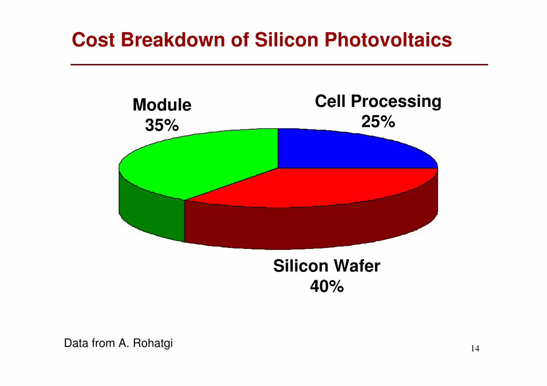
Silicon Wafer40%
Cell Processing25%
Module35%
Data from A. Rohatgi
Cost Breakdown of Silicon Photovoltaics

15
Lowering Cost of Solar Cells
� Thin Film Solar Cells
■ Multiple junction solar cells (a-Si:H, a-SiGe:H)
■ CdTe based cells (CdTe, CdS)
■ CuInSe2 (CIS) Ternary & Multinary compound solar cells
■ Multicrystalline/Microcrystalline silicon solar cells
■ Thin film GaAs solar cells
■ Organic solar cells
S. Deb 2004

16
Organics Photovoltaic
Zweibel et al. 2004
Spectrolab 40.7%
Efficiency of PV for Different Materials
17
Why Organic Solar Cells?

18
� Printing
■ Screen Pringing
■ Stamping
� Spraying
� Spin Coating
� Vaporisation
High-Throughput and Low-Cost Processing
19
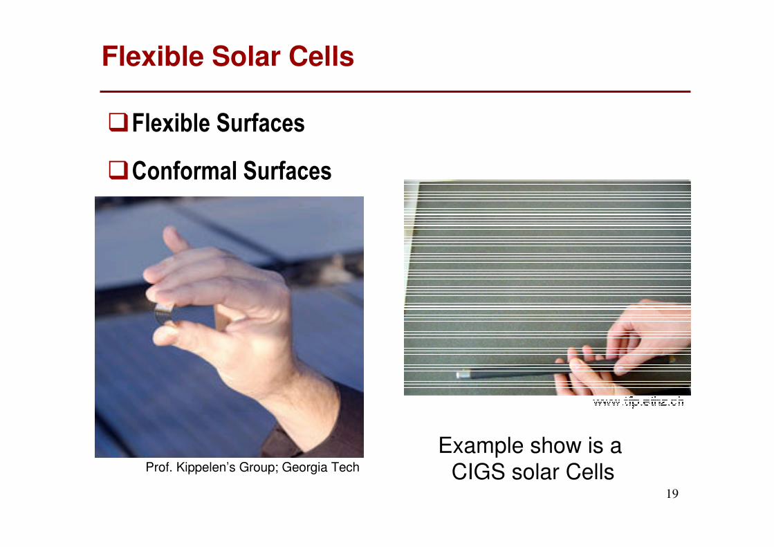
Flexible Solar Cells
�Flexible Surfaces
�Conformal Surfaces
Prof. Kippelen’s Group; Georgia Tech
Example show is a CIGS solar Cells

20
Eco-Friendly Technology
� Appropriate Process
� Biodegradable Molecule

21
Background
22
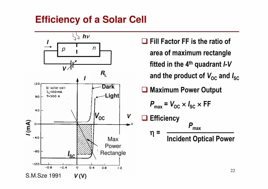
Efficiency of a Solar Cell
� Fill Factor FF is the ratio of
area of maximum rectangle
fitted in the 4th quadrant I-V
and the product of VOC and ISC
� Maximum Power Output
Pmax = VOC × ISC × FF
� Efficiency
η η η η =
p n
V
I
I(m
A)
V (V)
VOC
ISC
I
V
Max
Power
Rectangle
Dark
Light
S.M.Sze 1991
Pmax
Incident Optical Power
RL
hνννν

23
Classic p-n Junction Photovoltaic Cell
• Incident photon immediately forms mobile electrons and holes
e-
h+Ev
Ec
hνννν > > > > Eg= Ec - Ev
φbi
n-type p-type
Ebuilt-in
Efn
Efp
hνννν
Inorganic Semiconductor
Ef
-ve +ve

24
hν
h+
Exciton
e-
h+
e-
Hole Transport
Layer
Electron Transport
LayerCathodeAnode
Photon Absorption Exciton Formation
Exciton Dissociation
Exciton Diffusion
Charge Transport & Collection
e-
EHP Formation
Organic Solar Cells Operation
A Heterojunction Organic Solar Cell Structure
by diffusion

25
Photovoltaic Process In Organic Solar Cells
�
Light
ReflectedAway
����
Photons
NotAbsorbed
����
Coupling
of sunlightinto
solar cell
Absorption
of incidentphotons
Creation
of ‘free’charges
Separation
of chargesby built-inE field
ChargesRecombine
����
ChargesRecombine
����
Collection
of chargesat
electrodes
Creationof
excitons
ExcitonsRecombine
����
Su
nlig
ht
26
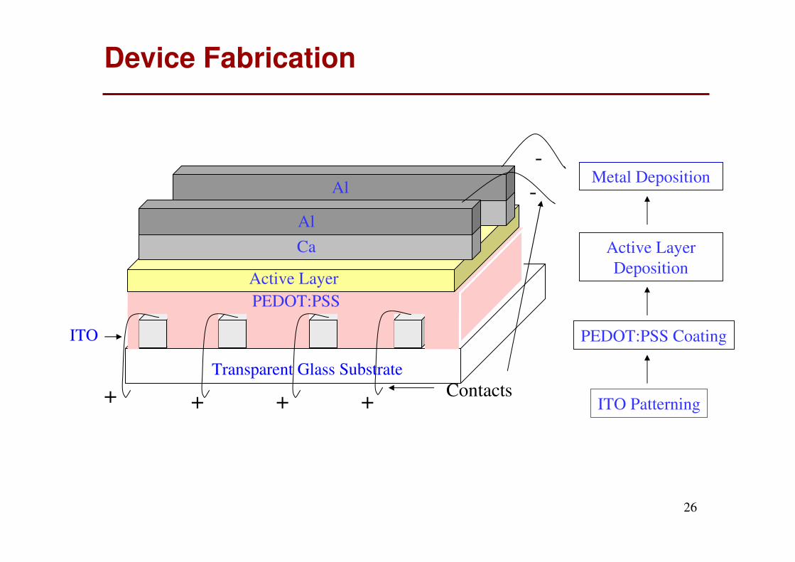
ITO Patterning
PEDOT:PSS Coating
Active Layer
Deposition
Metal Deposition
Device Fabrication
PEDOT:PSS
Active Layer
Ca
Ca
ITO
Al
Al
Contacts+ + + +
-
-
Transparent Glass Substrate

27
www.sciencemag.org SCIENCE VOL 317 13 JULY 2007 pp. 223-225
Tandem Cell: Jsc = 7.8 mA cm-2, Voc = 1.24 V, FF = 0.67 and η = 6.5%
Highest Efficiency Reported OSC Till Date

28
Organic Solar Cell Work at IIT K

29
The Team
� Prof. Satyendra Kumar (Physics)
� Dr. Ashish Garg (MME)
� Prof. Baquer Mazhari (EE)
� Prof. R. Gurunath (Chemistry)
� Dr. S.P. Das (EE)
� Dr. P.S. Sensarma (EE)
� Dr. R.S. Anand (EE)
� Dr. Vibha Tripathi (EE)
� Prof. Y.N. Mohapatra, Prof. Deepak Gupta, Prof. Monica Katiyar,
Dr. Siddhartha Panda, Dr. Narain, …
� S. Sundar Kumar Iyer
30
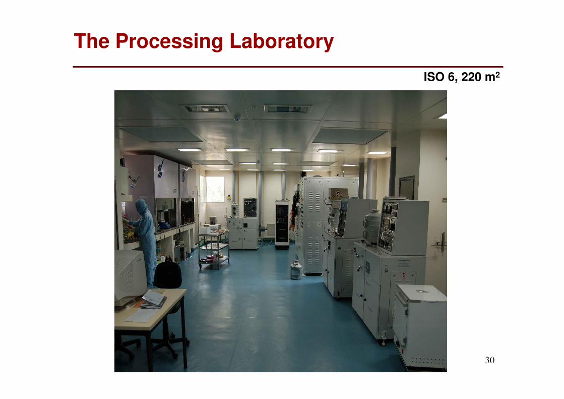
The Processing Laboratory
ISO 6, 220 m2

31
Characterisation Facilities
32
Three Pronged Approach
� Increasing efficiency of device
■ Physics and circuit model of organic solar cells
■ Choice of Material
■ Structure – Blend, Bilayer, Tandem …
■ Process Optimisation
� Reliability and Stability
■ Choice of Material
■ Mechanism of Degradation
■ Encapsulation Techniques
� New & emerging technology issues
■ Novel methods of fabrication
■ System level issues

33
Organic Solar Cell Model
� IL is a function of voltage
� Exciton generation IP is a constant
B. Mazhari 2006
IP
Rshunt, int.
D1
D2
Vint
Rs, int.
Ddark
+
-
V
I
RSH
RS
New Model
+
-
V
I
RSH
RS
IL
Traditional Model

34
Optical Efficiency ηηηηO
�� � Optical losses maybe due to
■ Reflection at the surface �
■ Unabsorbed light leaking out �
� Solutions
■ Anti Reflection Coating (ARC)
■ Texturing the top surface
■ Concentrators
■ Thickness of layers
Device
Back electrode
ηηηηO = 1-R where
R =(n1-n0)
2 + κκκκ2
(n1+n0) + κκκκ2
ni : refractive index of medium i
κκκκ: attenuation coefficient in device
n0=1 for air
n1, κκκκ

35
Light Trapping by TiO2 Nanoparticles
300 400 500 600 700 800 900 1000
0
10
20
30
40
50
60
70
80
90
100
Re
fle
cta
nce
(%)
λ (nm)
P3HT-PCBM-TiO2_40
��������
Device
Back electrode
300 500 700 900λλλλ (nm)
100
80
60
40
20
0
Refl
ecta
nc
e (
%)
P3HT:PCBM + TiO2
P3HT:PCBM
Jyoti Singh 2008
TiO2 particle is dispersed in the P3HT:PCBM blend

36
Cathode Variation
Illumination:
AM1.5D 100 mW cm-2
Nitin Sahai 2008
Glass
Active Area
Al
Ca
ITO
Cu
rren
t D
en
sit
y (
mA
cm
-2)
Voltage (V)

37
Effect of Post Process Anneal
P3HT: PCBM BlendHeterostructure
Vinod Pagare 2007
Aluminium Cathode
Polymer Blend
PEDOT:PSS
ITO Glass
38
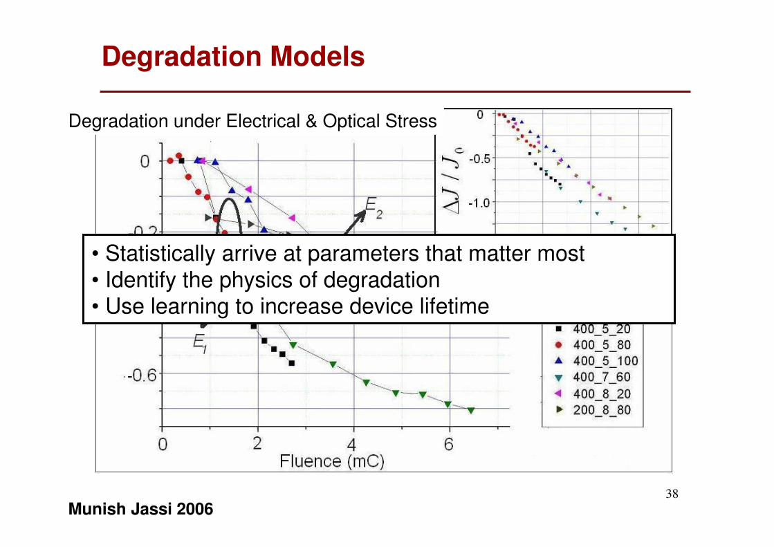
Degradation Models
Munish Jassi 2006
Degradation under Electrical & Optical Stress
• Statistically arrive at parameters that matter most
• Identify the physics of degradation• Use learning to increase device lifetime
39
Summary
�Organic solar cells offers unique opportunities in future
■ Low-cost high volume production
■ Distributed production
■ Environmentally benign devices
�Work at IIT Kanpur
■Molecule and material level
■ Process
■ Device level
■ Circuit level
■ System level
40
Let us make Organic Solar Cells Happen!