overload relay & contactor
DESCRIPTION
relays & contactors-jiguTRANSCRIPT
Over Load Relay & Contactor for StarterMay 20, 2011 4 Comments
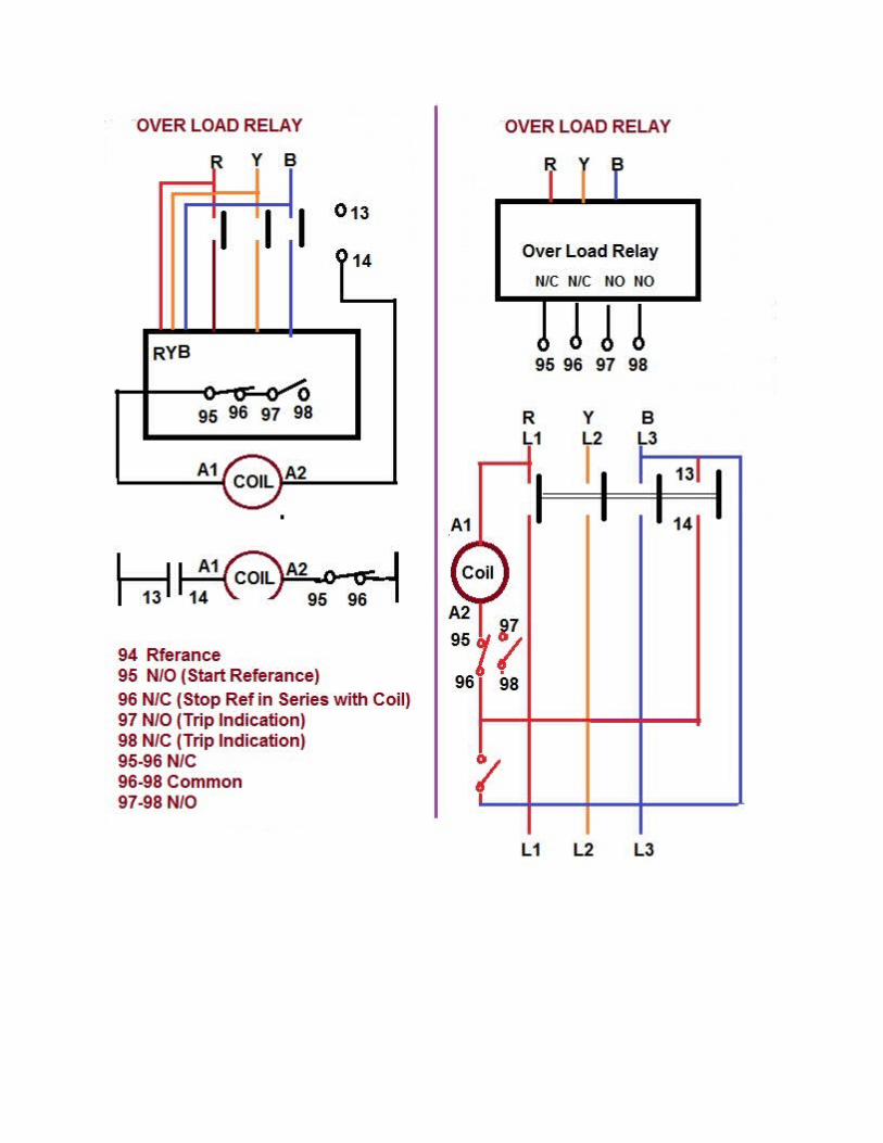
Over Load Relay & Contactor for Motor Starter:
Types of Over Load Relay:1. Class 10: Would Trip after 10 seconds.2. Class 20: Would Trip after 20 seconds.3. Class 30: Would Trip after 30 seconds.
Over Load Relay should be set 115% to 130% of Motor Full Load Current. Class 10 is faster than Class 20 and Class 30 over Load Relay.
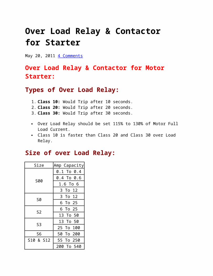
Size of over Load Relay:
Size Amp Capacity
S00
0.1 To 0.40.4 To 0.61.6 To 63 To 12
S0 3 To 126 To 25
S2 6 To 2513 To 50
S3 13 To 5025 To 100
S6 50 To 200
S10 & S1255 To 250200 To 540300 To 63
Contactor Coil:
Coil Voltage (40 To 50 Hz)
Suffix
24V T48V W110V To 127V A220V To 240V B
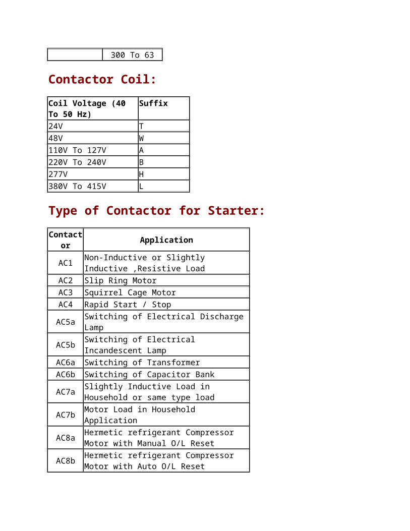
277V H380V To 415V L
Type of Contactor for Starter:
Contactor Application
AC1 Non-Inductive or Slightly Inductive ,Resistive Load
AC2 Slip Ring MotorAC3 Squirrel Cage MotorAC4 Rapid Start / StopAC5a Switching of Electrical Discharge LampAC5b Switching of Electrical Incandescent LampAC6a Switching of TransformerAC6b Switching of Capacitor Bank
AC7a Slightly Inductive Load in Household or same type load
AC7b Motor Load in Household Application
AC8a Hermetic refrigerant Compressor Motor with Manual O/L Reset
AC8b Hermetic refrigerant Compressor Motor with Auto O/L Reset
AC12 Control of Restive Load and Solid State Load with optocoupler Isolation
AC13 Control of Restive Load and Solid State with T/C Isolation
AC14 Control of Small Electro Magnetic Load ( <72VA)AC15 Control of Small Electro Magnetic Load ( >72VA)
Making and Breaking Capacity of Contactor:
Contactor Making Capacity(Amp)
Breaking Capacity (Amp)
AC1 1.5 X motor rated current
1.5 X motor rated current
AC2 4 X motor rated current 4 X motor rated currentAC3 10 X motor rated current 8 X motor rated currentAC4 12 X motor rated current 10 X motor rated currentAC5a 3 X motor rated current 3 X motor rated currentAC5b 1.5 X motor rated
current1.5 X motor rated current
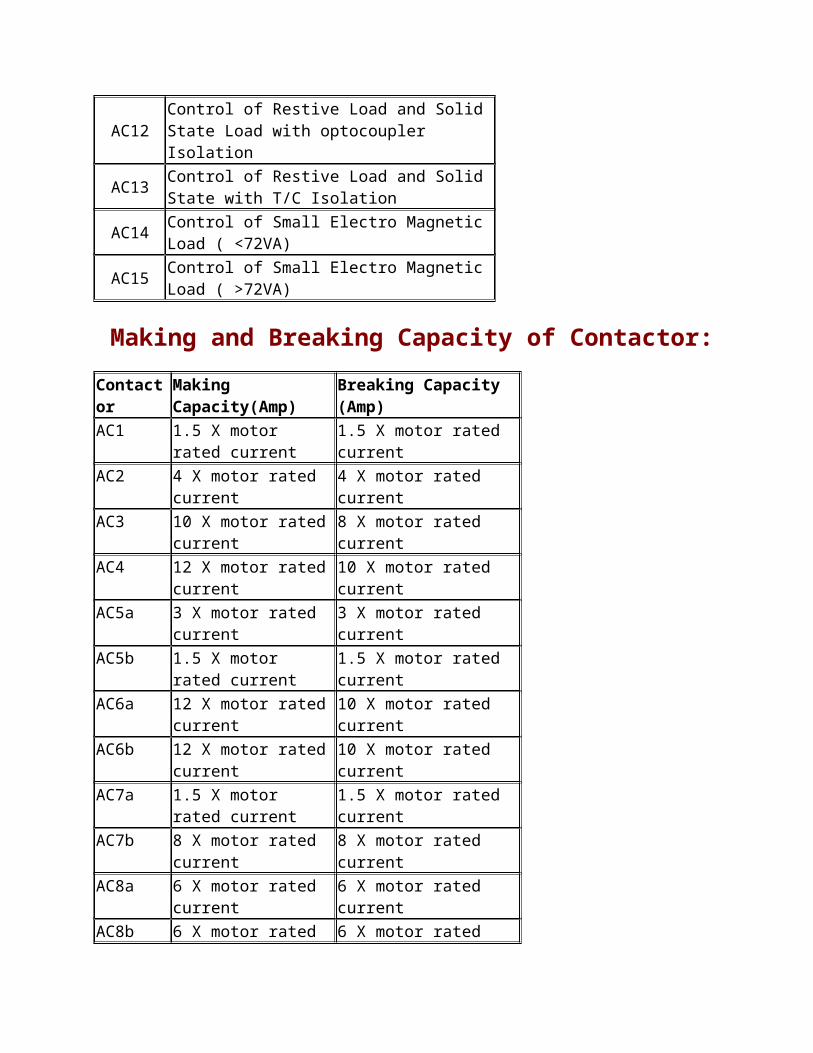
AC6a 12 X motor rated current 10 X motor rated currentAC6b 12 X motor rated current 10 X motor rated currentAC7a 1.5 X motor rated
current1.5 X motor rated current
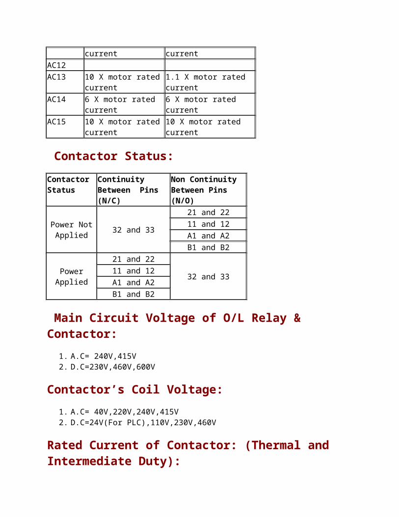
AC7b 8 X motor rated current 8 X motor rated currentAC8a 6 X motor rated current 6 X motor rated currentAC8b 6 X motor rated current 6 X motor rated currentAC12 AC13 10 X motor rated current 1.1 X motor rated currentAC14 6 X motor rated current 6 X motor rated currentAC15 10 X motor rated current 10 X motor rated current
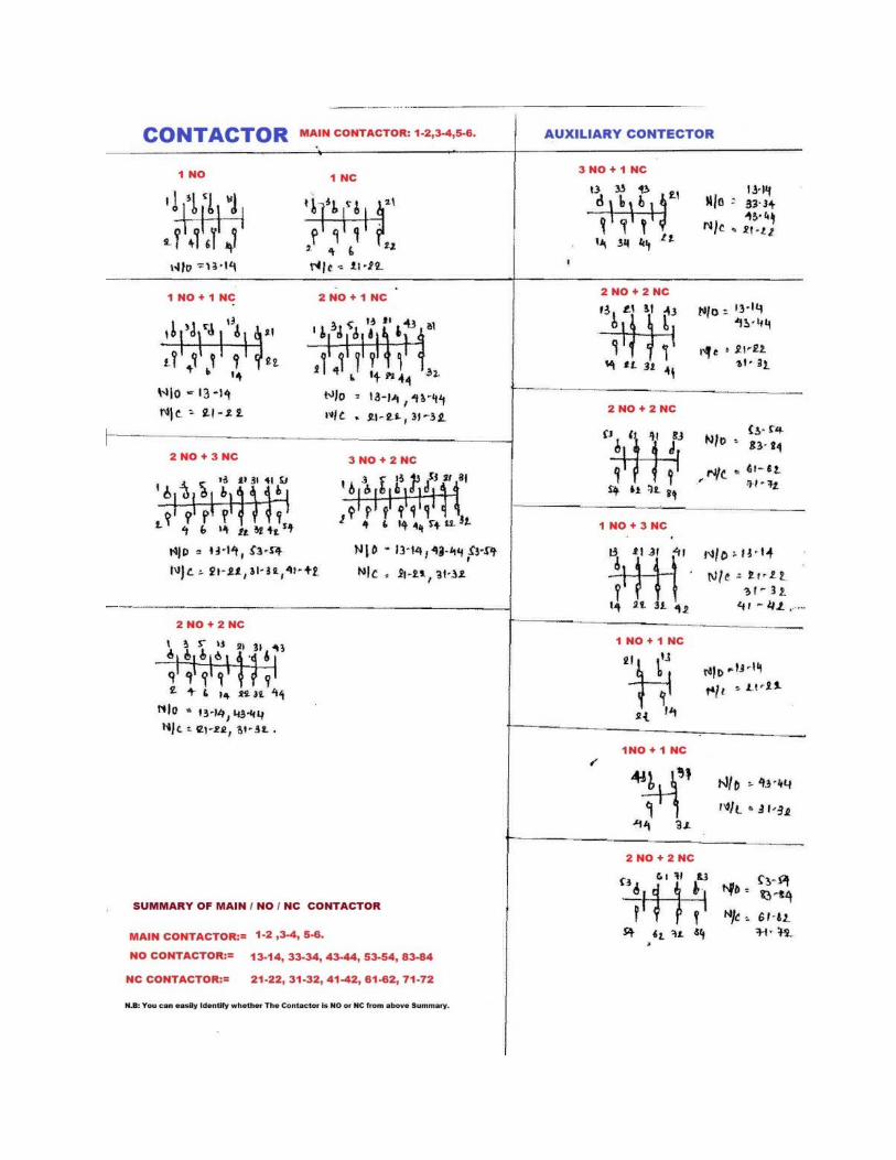
Contactor Status:
Contactor Status
Continuity Between Pins (N/C)
Non Continuity Between Pins (N/O)
Power Not Applied 32 and 33
21 and 2211 and 12A1 and A2B1 and B2
Power Applied
21 and 22
32 and 3311 and 12A1 and A2B1 and B2
Main Circuit Voltage of O/L Relay & Contactor:1. A.C= 240V,415V2. D.C=230V,460V,600V
Contactor’s Coil Voltage:1. A.C= 40V,220V,240V,415V2. D.C=24V(For PLC),110V,230V,460V
Rated Current of Contactor: (Thermal and Intermediate Duty):
1. A.C= 6,10,16,25,63,100,160,200,315,400,630,800 Amp2. D.C= 16,20,80,160,315,1250,8000 Amp.

Contactor / Relay Setting / Fuse / Cable for DOL STARTER
H.P KW FLC Contactor Size (Amp)
Relay setting Fuse Cable (mm2)Min Max Cu Allu
0.5 0.37 1 - 0.8 1.17 4 1 1.50.75 0.55 1.3 9 1 1.5 4 1 1.5
1 0.74 1.9 9 1.6 2.3 6 1.5 2.51.5 1.11 2.6 9 2 3 6 1.5 2.52 1.49 3.7 9 2.5 3.7 10 1.5 2.53 2.2 4.8 9 4 5.9 16 1.5 2.55 3.73 7.8 9 6.3 9.4 20 1.5 2.57 5.22 11.2 12 8 11.7 25 2.5 410 7.46 16 16 12.5 18.7 25 4 6
12.5 9.32 19 32 16 23.4 32 4 615 11.19 20.8 32 16 23.4 50 6 1020 14.92 28 32 20 30 50 6 1025 18.65 34 38 32 37.4 63 10 1630 22.38 40 45 32 47 80 16 2540 29.84 53 63 50 59 100 25 3550 37.3 65 70 57 65.5 125 25 50
60 44.76 78 85 70 88.9 125 25 5075 55.95 96 110 85 98.2 160 50 70100 74.6 131 140 115 168 200 70 95125 93.25 156 170 115 168 250 120 150150 111.9 189 205 160 234 315 150 240180 134.28 227 250 160 234 355 185 300215 160.39 271 300 200 299 400 - -270 201.42 339 400 250 374 500 - -335 249.91 338 475 320 468 500 - -
Relay Range & Back up Fuse for DOL Starter
H.P KW
Full Load
Current (amp)
Relay Rang(Amp)
Back Up Fuse
Min Max
10 7.5 13.6 13 To 20 25 5012.5 9.3 17 13 To 20 25 5015 11.2 20 20 To 30 35 8020 14.9 28 20 To 30 60 8025 18.7 35 30 To 45 60 10030 22.4 40 30 To 45 80 10035 26.1 47 45 To 63 80 125Relay Range & Back up Fuse for Star / Delta Starter
H.P KW
Full Load
Current (amp)
Relay Rang(Amp)
Back Up Fuse
Min Max
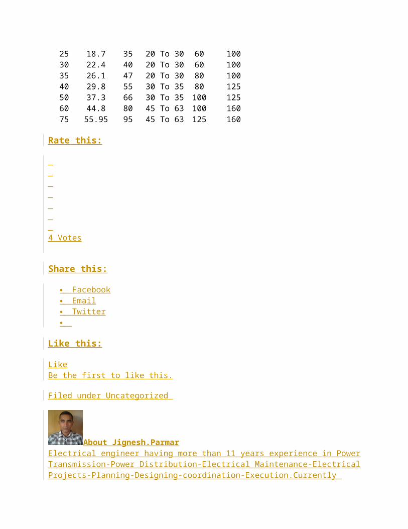
20 14.9 28 13 To 20 60 6025 18.7 35 20 To 30 60 10030 22.4 40 20 To 30 60 10035 26.1 47 20 To 30 80 10040 29.8 55 30 To 35 80 12550 37.3 66 30 To 35 100 12560 44.8 80 45 To 63 100 16075 55.95 95 45 To 63 125 160
Rate this:
4 Votes

Share this:
Facebook Email Twitter
Like this:
LikeBe the first to like this.
Filed under Uncategorized
About Jignesh.ParmarElectrical engineer having more than 11 years experience in Power Transmission-Power Distribution-Electrical Maintenance-Electrical Projects-Planning-Designing-coordination-Execution.Currently associated with one of the leading business group as a Asst.Manager at Ahmedabad,India.Freelancer Programmer of Advance Excel.Design useful Excel Sheets of Electrical Engineering as per IS,NEC,IEC,IEEE codes. Technical Author for "Electrical Mirror" and "Electrical India" Magazines. Technical Blogger. Familiar with English, Hindi, Gujarati, French languages. Share experience and knowledge and help technical enthusiasts to find suitable solutions and updating themselves on various Engineering Topics.
4 Responses to Over Load Relay & Contactor for Starter
1. Hament Kaushik says:
September 30, 2011 at 8:13 am
thanks sir jitis is very usfull for us.
Reply
2. Saahib Ghouse says:
November 12, 2011 at 9:58 am

Please provide relay coordination examples ..hand calculations if included and developing curves, selection of relay curves.Thumb rules or any logic or technic or any hidden knowledge in performing relay coordination studies and settings.
Thanks for your knowledge sharing…you are a real master..
Best Regards,
Reply
3. nikhil says:
May 19, 2012 at 6:16 am
sir please insist me the contactor size for the star delta stater also…….. and simple hand cluculations….
Reply
4. TANVEER SHAH says:
May 19, 2012 at 11:44 am
definitely your sharing valueable knowledge is a great task remembered to be ever for comforting other keep it up good job good contribution wish u more grow to show such a contributon to deliver spreading valueable knowledge.
thanks
TANVEER SHAH
Reply
Leave a Reply
Enter your comment here... guest
Authors
Jignesh.Parmar
Blog Stats
529,686 hits
About Me:
Post Comment 490 0
1348230753
210d24b17c
1042806957028

Electrical engineer having more than 11 years experience in Power Transmission-Power Distribution-Electrical Maintenance-Electrical Projects-Planning-Designing-coordination-Execution.Currently associated with one of the leading business group as a Asst.Manager at Ahmedabad,India.Freelancer Programmer of Advance Excel.Design useful Excel Sheets of Electrical Engineering as per IS,NEC,IEC,IEEE codes. Technical Author for "Electrical Mirror" and "Electrical India" Magazines. Technical Blogger. Familiar with English, Hindi, Gujarati, French languages. Share experience and knowledge and help technical enthusiasts to find suitable solutions and updating themselves on various Engineering Topics.
SUPPORT THIS SITE
BUY ELECTRICAL NOTES IN PDF
Recent Posts
Abstract of over current Protection of Transformer (NEC 450.3) Difference between Bonding, Grounding and Earthing Safety Clearance for Transformer Safety Clearance for Electrical Panel Electrical Safety Clearance (Part-6) Electrical Safety Clearance (Part-5) Electrical Safety Clearance (Part-4) Electrical Safety Clearance (Part-3) Electrical Safety Clearance (Part-2) Electrical Safety Clearance (Part-1) Impact of Floating Neutral in Power Distribution Parallel Operation of Transformers Vector Group of Transformer Auto Transformer Connection Scott-T Connection of Transformer Zig-zag Connection of Transformer Star-Delta Connection of Transformer Delta-Star Connection of Transformer Delta-Delta Connection of Transformer Star-Star Connection of Transformer
Follow Blog via Email
Enter your email address to follow this blog and receive notifications of new posts by email.
Join 848 other followers
Search for:
Proud to be an IndiBlogger
electricalnotes.wordpress.c...85/100
EEP
DOWNLOAD BOOKS-NOVELS
Top Clicks
jiguparmar.com electricalnotes.files.wor… electricalnotes.files.wor… electricalnotes.files.wor… electricalnotes.files.wor…
Archives
subscribe 20999440 http://electricalno w idget blog_subscription c3371a0e26
Follow
Search
September 2012 (3) August 2012 (7) July 2012 (2) May 2012 (7) April 2012 (2) March 2012 (3) February 2012 (3) January 2012 (1) December 2011 (3) November 2011 (2) October 2011 (4) September 2011 (2) August 2011 (1) June 2011 (5) May 2011 (3) April 2011 (12) March 2011 (17)
Pages
Abstract o Abstract of CPWD-Part 1 o Abstract of IE Rules o Abstract of IS Code.
IS 1255 IS 15652/11171/1445/1678 IS 3043 / 5039 IS 5613 IS 694 / 1554 / 11892
o IE Rules for DP Structure Electrical Notes Electrical Q&A
o Electrical Q&A Part-1 o Electrical Q&A Part-2 o Electrical Q&A Part-3 o Electrical Q&A Part-4
Electrical Tools
Recent Comments
Jignesh.Parmar on Abstract of over current Prote…Praveen Yadav on Electrical Tools sakawat on Abstract of over current Prote…Jignesh.Parmar on Abstract of over current Prote…Arun kumar Jain on Abstract of over current Prote…Jignesh.Parmar on Guideline to Design Electrical…