plan presentation guide
TRANSCRIPT

STATE of GEORGIA
DEPARTMENT OF TRANSPORTATION
Plan Presentation Guide
November 2002

GEORGIA DOT PLAN PRESENTATION GUIDE_____________________________
2
DOCUMENT REVISION RECORD Plan Presentation Guide
DATE DESCRIPTION OF REVISION 04/24/95 Revision #1 of the “GENERAL” section of each chapter (by GQI Plan Presentation Task Force) 05/25/95 Revision #2 of the “GENERAL” section of each chapter (by GQI Plan Presentation Task Force) 08/10/95 Added the contents of each chapter [by the authors (CEC-GA members) of the Plan Presentation Guide] except Chapter 3 (Typical Sections) 09/25/95 Incorporated comments from the peer reviewers 11/09/95 Added Chapter 3 and revised Chapter 17 (Bridges and Structures) per Tom Turner’s Comments 11/29/95 Incorporated comments from the Georgia DOT; issued a final draft to be presented at the GQI Workshop on 12/07/95. 10/30/97 Revised requirements for erosion control plans in Chapter 7
GEORGIA DOT PLAN PRESENTATION GUIDE_____________________________
3
TABLE OF CONTENTS
Introduction
Chapter 1 Sequence of Plans Preparation
Chapter 2 Project Plan Information
Chapter 3 Typical Sections
Chapter 4 Quantities and Estimates
Chapter 5 Roadway Plans
Chapter 6 Drainage
Chapter 7 Erosion and Sediment Control Plans
Chapter 8 Roadway Profiles
Chapter 9 Roadway Cross Sections
Chapter 10 Intersections and Interchanges
Chapter 11 Utilities
Chapter 12 Maintenance of Traffic, Sequence of Operations, and Staging
Chapter 13 Signing and Pavement Marking
Chapter 14 Signalization
Chapter 15 Highway Lighting
Chapter 16 Landscaping
Chapter 17 Bridges and Structures
Chapter 18 “Georgia Standard Drawings” and Special Details
Chapter 19 Special Provisions
Chapter 20 Right-of-Way Plans
Chapter 21 Documentation of Design and Quantities
Chapter 22 Checklists
Appendix Sample Metric Plan Set

GEORGIA DOT PLAN PRESENTATION GUIDE_____________________________
4
INTRODUCTION PURPOSE
The Georgia Quality Initiative (GQI) is a statewide outgrowth of the National Quality Initiative, a partnership of transportation entities working together to improve the quality of the nation's highways. As one of the initiatives, the GQI Steering Committee created a team from public and private sector organizations to jointly focus on the improvement of highway construction plans. It was determined by the team that quality improvements were attainable by developing a Plan Presentation Guide to assist designers in the presentation of the work to be accomplished and thereby making plans more efficient for the user.
These criteria establish, define, and clarify procedures and standards for plans to be used by the Department. These criteria are not intended to establish design processes; rather, they are guidelines to assure that all drawings have a uniform appearance and include all pertinent information, avoid unnecessary information, and reflect high quality workmanship.
Engineers and technicians are responsible for ensuring that these criteria are implemented accurately and that the drawings show the information completely, clearly, and legibly. In accordance with the U.S. Department of Transportation's mandate that all plans, surveys, and estimates be prepared in metric units by January 1, 2000, the Department adopted metric units for all plans effective October 1, 1996. Therefore, the International System of Units (SI) is used throughout this Plan Presentation Guide. Dual units (the use of English and metric units) is not allowed except on right-of way plans.
GEORGIA DOT PLAN PRESENTATION GUIDE_____________________________
5
CHAPTER 1
SEQUENCE OF PLANS PREPARATION GENERAL The construction plans and the specifications are the key documents on which the contractor bases his bid for a construction project. These documents are used in the construction of the project. Hence, it is imperative that the construction plans and specifications set forth the work to be done in a logical, concise, and consistent manner to avoid misinterpretation. The construction plans should be prepared and coordinated to complement the Department's Plan Development Process (PDP), which provides a sequence of events, while systematically undergoing various stages of review and revision to ensure technically correct and clear plans. REQUIRED INFORMATION FOR URBAN AND ROADWAY DESIGN PLANS Preliminary Roadway Plans UConceptual Layout U - Initial design begins with a conceptual alignment. In most cases an initial concept layout will be provided by the Department. Alternate concept layouts shall then be prepared to ensure a buildable, cost effective project. These concept alternatives should be submitted to the Department for approval. After approval has been issued, a Revised Concept Report shall be prepared if differences exist between the initial concept and the alternate concept of the project. UDatabase PreparationU - After a conceptual alignment has been approved, database preparation should begin. The Department may furnish initial mapping. If not, the plan preparer will furnish mapping. Required surveys will then be performed and additional information within the project limits will be gathered to develop accurate and up-to-date base mapping. These required surveys shall include detailed right-of-way and property surveys, drainage surveys, and additional location surveys as needed (see the "Scope and Procedure" and appendices in the Consultant Services Agreement). UPlan Sheet PreparationU - Prepare preliminary plans using the approved concept plan along with the completed database. Upon completion of preliminary plans, submit plans to the Department for review. Incorporate review comments into the Preliminary Plans and resubmit for approval. After approval, the Department will schedule a Preliminary Field Plan Review (PFPR). Comments made in the PFPR report shall be addressed in the plans prior to submission and approval of right-of-way plans. Right-of-Way Plans UPlan Sheet PreparationU - Develop right-of-way plans only after receiving written "Notice to Proceed" from the Department. Prepare right-of-way plans based on the developed preliminary plans and according to the requirements for preparation of right-of-way plans as found in the Consultant Services Agreement. Upon completion of right-of-way plans, submit plans after the PFPR to the Department for review and approval. Incorporate corrections into the right-of-way plans and resubmit for approval. URight-of-Way StakingU - Upon receiving written "Notice to Proceed" stake the required right-of-way along the entire length of the project and schedule a Field Right-of-Way Plan (FRWP) review. Make all revisions resulting from the FRWP review and continue to revise the plans through the design process to incorporate any additional changes that should occur. Final Roadway Plans UPlan Sheet PreparationU - Base final plans on the developed preliminary plans, and according to the requirements for preparation of construction plans per the Department's guidelines. Upon completion of pre-final plans and specifications, submit the plans to the Department for a Final Field Plan Review (FFPR). Incorporate corrections into the final plans and resubmit for approval. A FFPR will then be scheduled by the Department where the plans will be reviewed for completeness and uniformity of presentation per the guidelines set forth in the Plan Presentation Guide. After all review comments from
GEORGIA DOT PLAN PRESENTATION GUIDE_____________________________
6
the FFPR have been incorporated into the final plans, the Department shall declare the construction plans adequate for submission as final plans. SHEET LAYOUT When the plans are completed, assemble the sheets in the following sequence (this plan assembly is to be used as a general guide and may be changed to better fit an individual project, or to include any sheets not listed herein):
ο Cover ο Index ο Revision Summary Sheet ο Typical Sections ο Summary of Quantities (Roadway and Signing and Marking) ο Detailed Estimate ο Traffic Assignments ο Aerial Photo Mosaics (on new location) ο Construction Layout Sheet ο Plan and Profile Sheets (mainline/profile can be on same or separate sheet) ο Plan and Profile Sheets (crossroads, side roads, local service roads and detours) ο Interchange Plan Sheets ο Profile of Ramps or Side Streets ο Driveway Profiles ο Retaining Wall Envelopes ο Drainage Map ο Drainage Profiles ο Miscellaneous Interchange Details ο Staging and Detour Plans (with cross sections) ο Special Grading Sheets ο Wetland Mitigation Sheets ο Utility Plans ο Signing and Marking Plans and Details ο Traffic Signal Plans and Details ο Lighting Plans and Details ο Sound Barrier Plans and Details ο Erosion and Sediment Control Plans ο Earthwork Cross Sections ο Borrow Pit Location and Notes ο Construction Details ο Special Design Culverts ο Georgia Standards ο Retaining Wall Plans and Details ο Bridge Plans and Details
After the sheets have been assembled in order, number each sheet consecutively beginning with the cover sheet as No. 1 and continuing through the plan set. Make an index listing all sheets by number and description thus far. At this point make a thorough check of the plans listing all of the construction details, special design culverts, and Georgia Standard Drawings numerically. The number of the last sheet in the plans will be shown on every sheet in the plans and will never change after the plans have been submitted to the Office of Engineering Services for their review regardless of future revisions adding or omitting sheets in the plan assembly. The index may now be completed and the latest revision dates shown for construction details, special design culverts, and Georgia Standards. The total number of sheets in the plans should be shown immediately below the index. This number will not necessarily be the same number as the last sheet in the plans and may be shown in pencil since it is subject to change each time a sheet is added to or omitted from the plans. If a sheet is added after the final sheets are numbered and the final plans approved, place the sheet in the appropriate location and assign it an alpha designation.

GEORGIA DOT PLAN PRESENTATION GUIDE_____________________________
7
If a revision is made after the final plans have been let to contract, mark the original sheet "VOID" and insert a new sheet with the applicable revision and an alpha character included in the sheet listing. Make any subsequent revisions to the new sheet included in the plans. The voided sheet remains in the plans.
GEORGIA DOT PLAN PRESENTATION GUIDE_____________________________
8
CHAPTER 2
PROJECT PLAN INFORMATION GENERAL Project plan information should be included in the construction plans utilizing a general note sheet. This sheet would include construction notes that are project specific and are not covered under the current Standard Specifications and Supplemental Specifications, Special Provisions, Georgia Standard Drawings, and/or Special Details. Notes that are needed in the construction contract may be included in the General Notes if special attention is necessary to eliminate a possible source of errors or conflict, or to expedite the work. HTUCOVER SHEET UTH
A cover sheet is required for each set of construction plans. The cover sheet is extremely important for contract purposes and for project identification. The cover sheet should include but is not limited to information pertaining to the project name, project number, project identification number, county, congressional district, and a standard note that directs attention to the GDOT Standard Specification book. In addition to information on the cover sheet to identify the project, information about the project should be shown including a project location map, project limits (shown in a large scale), boxes containing length of project, design traffic, and if room is available, a legend of items used in the plans and a sheet layout diagram. Final items that must be shown on the cover sheet include a signature box for the Chief Engineer, or responsible official (if applicable), with an area for the date the plans are completed and the Professional Engineer's stamp. This sheet should be the first sheet in the set of plans. A cover sheet of similar nature is also required for the right-of-way plans. The major difference is that a signature box is required for the State Right-of-way Engineer and not the Chief Engineer. INDEX SHEET An index is required for each set of construction drawings to help the user in identifying plan contents. The index can be included on the cover sheet on smaller projects with few sheets, but normally will be included as a separate sheet directly following the cover sheet. The index should include a description of each type of drawing with the corresponding sheet numbers. A listing of all GDOT standards and construction drawings should also be shown along with the corresponding standard number, the most recent revision date of the standard, and the sheet number. A column or area should be available on the sheet for later additions or deletions of sheets and a total of all sheets should be shown. The sheet should be labeled "INDEX SHEET." REVISION SUMMARY SHEET Revisions to a set of construction plans should be detailed for the purpose of keeping a record of changes to the construction plans after final plans have been submitted. For this reason, a revision summary sheet will be required for each set of construction plans. The revision summary sheet will consist of three columns (in addition to the normal project information in the title blocks). The first column describes the date on which the revision was made; the second column locates the revision in the plan set; and the third column contains a description of the revision, described in enough detail to quickly understand the context of the revision. The revision summary sheet will typically be the second or third sheet in the set of plans following directly behind the Index Sheet, or the cover sheet if it contains the index, and should be labeled "REVISION SUMMARY SHEET."

GEORGIA DOT PLAN PRESENTATION GUIDE_____________________________
9
CHAPTER 3
TYPICAL SECTIONS GENERAL Typical sections depict the design elements of the proposed roadway and shall be drawn in the form of cross sectional views depicting the work which is standard or typical within certain station-to-station limits. Typical sections for a project are established during conceptual and early preliminary design by the engineer. Typical sections should be drawn to scale and vertical dimensions exaggerated for clarity. Typical sections should show typical conditions only. Conditions that prevail for short distances may be shown as a partial section with its appreciable limits specifically defined. When more than one typical section is necessary for a project, show the station limits of each section below each typical section title. Include transitions from one typical section to another in the stationing of one or the other typical section. Number typical sections consecutively. When partial sections are necessary to cover the details, show these sections near the main typical section to which they apply. If space is not available, they may be grouped on a separate sheet. REQUIRED INFORMATION UPavementU - Include paving and base elements on typical sections. Exaggerate the vertical scale to clearly indicate individual course. The base and paving elements shall comply with the pavement design provided by the design engineer. Label each layer as to thickness or spread rate, and type of material to be used. Show a leveling course on typical sections where the existing pavement is to be retained and overlaid. If milling is required provide a note to define the limits and intent of removal. UCross SlopesU - Express the cross slopes of roadway pavement, shoulder surfaces, sidewalks, and bridge decks as percentages. Show the outer slopes by ratio, horizontal to vertical (e.g., 4:1, 2:1). Show feathering details and/or notes when resurfacing in urban gutter areas is specified. For rural shoulders, specify slope rates for high side and low side shoulders. ULane and Shoulder WidthsU - Provide lane and shoulder widths on typical sections. Widths shall comply with the latest edition of AASHTO's, "A Policy on Geometric Design of Highways and Streets" and AASHTO’s, "Roadside Design Guide" for the class and type or classification of roadway shown in the design data, topographical classification, projected traffic data, and as specified by the design engineer. Show minimum to maximum dimensions for variable widths. UGuardrailU - For projects with guardrail, show a typical guardrail section with additional shoulder width required for guardrail and anchorage placement. URight-of-WayU - Show ranges of widths where applicable. UCurbsU - Label the curb and gutter on typical sections per the Department's standard. Show the curb and gutter "spilling out", or sloped in the same direction and rate as the super elevation, when the curb and gutter is on the high side. USidewalksU - Provide sidewalk information on typical sections at locations or stations required by the design engineer. Specify the width and cross slope of the sidewalks. UStationsU - Show station ranges on typical sections applicable to each typical section number. Place typical sections in order as they will be used along the alignment. Flag the profile grade line (PGL) and "Superelevation (S.E.) Rotation Point." UEasementsU - Show utility or other easements, if typical in width.

GEORGIA DOT PLAN PRESENTATION GUIDE_____________________________
10
SHEET LAYOUT Draft typical sections to scale. Exaggerate the vertical dimensions for clarity. Include a typical section that shows resurfacing and widening. Include a typical section for cross streets and list all applicable streets. Include a superelevated typical section when there are curves in the horizontal alignment. Show the shoulder cross slope rates and direction on the high and low sides of the superelevation and show the curb and gutter "spilling out" on the high side of the superelevation. Include a pavement material schedule. Include a "Slope Controls" table specifying the front and back slopes to use for corresponding cuts and heights of fill. Include partial sections noting application of special features such as guardrail, retaining walls, treatment of turn lanes, special shoulder or grading sections, etc. MISCELLANEOUS NOTES AND OTHER INFORMATION Include the following notes, when applicable, on the typical section sheets:
ο For superelevation rates and locations see roadway plans. ο Location of existing pavement varies with respect to the proposed construction centerline. ο See roadway plans for location of curb and gutter section. Shoulder may be graded away from
roadway to facilitate the slope tie to existing ground. See cross-sections for location. ο In excavated areas confined between existing pavement and proposed curb and gutter, Class "B"
concrete shall be placed in lieu of the base and paving specified on the typical section as appropriate. Payment will be made at the unit price bid for Class “B” Concrete Base and Pavement Widening. See construction detail.
ο The Allowable Range Table will be shown when an overlay of existing pavement is required. ο A detail showing underdrain pipe at curbed medians (grassed) - located at the lowest end of the
median - should be shown, when required. ο A detailed drawing showing the application of a pavement reinforcing mat should be shown for an
overlay or widening project as required. ο Show indentation rumble strips if required.
Link to sample typical section sheets: HTUSheet 1UTH, HTUSheet 2 UTH, HTUCrossroad TypicalUTH

GEORGIA DOT PLAN PRESENTATION GUIDE_____________________________
11
CHAPTER 4
QUANTITIES AND ESTIMATES GENERAL The Summary of Quantities tabulates individual summaries of all items to construct the project. The quantities may be itemized according to the roadway plan sheet where each item is shown. The arrangement of the quantity boxes on the Summary of Quantities sheets is dependent on the number used and the size each one must be to contain all of the necessary information. Aesthetics should be considered. Show standard notes or applicable designations under the appropriate box. On projects with multiple contracts or Federal-aid and non-Federal-aid quantities, make provisions to tabulate and summarize their respective quantities. The Summary of Drainage Quantities sheet shows the location, size, length, number, and type of drainage structures. This includes quantities associated with culverts, pipe, inlets, outlets and riprap. The Detailed Estimate generally follows the Summary of Quantities sheets in the plan set. The Detailed Estimate is a synopsis of pay quantities from the Summary of Quantities sheets and includes bid pay item numbers, units, and total quantity for each pay item. Generally, all items on the Summary of Quantities sheets shall be on the Detailed Estimate unless otherwise noted. The Summary of Drainage Quantities sheet and Detailed Estimate should reflect the Department’s format. REQUIRED INFORMATION Preliminary Plans The Summary of Quantities and Detailed Estimate are not to be included in the Preliminary Plans. Prepare a preliminary estimation of quantities from items which can be determined from the preliminary plans and used to determine a preliminary estimation of construction costs. This would include such items as paving, earthwork, guardrail, retaining walls, curb and gutter, drainage, grassing, erosion control, and other items which can be easily determined at this stage of plan development. Final Plans The Summary of Quantities and Detailed Estimate are to be included in the Final Plans. USummary of Quantities U - All items of construction indicated on the plan and profile sheets are to be reflected on the summary sheets unless it is stated that an item is included in the cost of another item. Another exception would be on small bridge replacement projects where quantities are small and pay items very limited. In this case, placing quantities only on the Detailed Estimate will suffice. Summarize all items by one of the following four groups:
ο USheet by Sheet U - Lump all quantities required on each individual sheet together. Example: Paving Quantity Box, Temporary Silt Fence, Erosion Check Fence and "As Directed By Engineer Quantities."
ο UStation by StationU - List quantities that will be required from a given beginning station to a given ending station. Example: Ditch Protection.
ο UExact Station U - List quantities that will be required at a specific location. Example: Drainage Structure, Sediment Basin, Spring Box and Summary of Driveway Quantities.
ο ULumpU - Quantities that will be required for the complete project. [Example: Grassing, Traffic Control and Erosion Control - Actual quantities for lump sum items are not listed in the plans.]

GEORGIA DOT PLAN PRESENTATION GUIDE_____________________________
12
All quantities are to be checked and verified for compliance with all design memos and directives currently in use by the Department, and that quantity recommendations in the Field Plan Review Report are applicable and incorporated into the plans. Add references to standard details to boxes as appropriate, such as Standard 9032B for curb or curb and gutter. Refer construction details and special designs by sheet number in the appropriate boxes. UDetailed Estimate U - Check to see that all items on the Summary of Quantities, which are pay items, are reflected on the Detailed Estimate sheet. [Note: If there are any items in the contract that are not to be paid for by the Department, they need to be listed in a separate column labeled "Non-Participatory Items." [Example: a sidewalk quantity in the plans but paid for by the County, City, etc.] Do not list in the Detailed Estimate items not paid for individually, such as items removed as clearing and grubbing or items included with other item payments. Perform the final verification between Summary of Quantities and Detailed Estimate sheets using two people. Copies of this check off should be made part of the summary file. Show the pay item number, description, and units verbatim from the Department "Pay Item Index." If the item does not appear in the "Pay Item Index," contact the appropriate person at the Department for assignment of a number and description. Quantities should be shown on the detailed estimate as whole units. Rounding up of quantities from Summary of Quantities to Detailed Estimate is appropriate. Do not round any quantities furnished by other disciplines (such as Bridge Design) or quantities that are measured "per each." See the appendices in the Consultant Services Agreement for rounding information. SHEET LAYOUT USummary of Quantities U - Prepare individual summary boxes for items such as Paving Quantities, Guardrail, Fence, Sodding, Grassing, Ditch Pavement, and Permanent Erosion Control. "Lump Sum" Items such as Grassing Complete, Clearing and Grubbing, and Temporary Erosion Control are to have quantity calculations, but listed in separated quantity boxes as lump sum items. Individual summary boxes are also to be set up for items such as Underdrain Pipe and Aggregate Surface Course for which quantities cannot be determined from the plans but are to be used by the Engineer as an estimation, which varies according to the size of the project. For storm sewers and drainage structures, tabulate the Summary of Drainage Quantities on a separate sheet by structure number (numerical order) and by system, providing station, location, size, length, type, and incidental quantities. Show acceptable culvert materials on the Summary of Drainage Quantities based on the recommendations from the soils report. Refer to Chart 1-1 of the Department's Drainage Manual for uses of different culvert materials. On smaller projects, the Summary of Quantities and the Summary of Drainage Quantities may be accommodated on one sheet. Box culverts are not to be included in the Summary of Drainage Quantities but are to be included in a separate table in the Summary of Quantities. Summarize quantities for storm drain and side drain flared-end sections in separate columns. Place items which are relative to each other together in the same box. For example, spillways adjacent to approach slabs should have the slope drain, pipe, and concrete aprons in the same box as the area of approach slab. Temporary erosion control items should be summarized in accordance with the Department's "Guidelines for Soil Erosion and Control Plans" and the Construction Detail sheets identified as "Uniform Code System for Soil Erosion and Sediment Control." Traffic control is lump sum, but some relative items are paid for separately, such as Guardrail Anchors, Temporary Attenuators, and Temporary Concrete Barriers and Barricades, etc. The method and pick-
GEORGIA DOT PLAN PRESENTATION GUIDE_____________________________
13
up/drop-off location for temporary barrier is to be specified. Also check for detour drainage structures, pavement widening for lane shifts, and aggregate specified for use at driveways or cross roads. Summary boxes for guardrail should contain separate columns for each type of beam and guardrail anchorage. Fence summary boxes are to include material and sizes for gates and fencing. UDetailed Estimate U - The Detailed Estimate sheet(s) are to be placed in the plans immediately following the Summary of Quantities sheets. The Detailed Estimate sheet is read from top to bottom with the top being the short side. Space and divide line items so as to provide a clear and legible detailed estimate. The normal sequence of items in making the Detailed Estimate is as follows:
ο Roadway Items ο Erosion Control - Permanent ο Erosion Control - Temporary ο Signing and Marking/Signal Items ο Concrete Bridge Culvert Items (each culvert listed separately) ο Retaining Walls and Alternates ο Bridge Items
MISCELLANEOUS NOTES AND OTHER INFORMATION Notes, if required, are to be placed under the corresponding quantity boxes. Each note shall consist of special requirement regulations, or directions prepared to cover the work which is not covered by the Standard Specifications or for general information. Use the following standard notes on the Summary of Quantities Sheets as applicable:
ο (Under Summary of Guardrail) "Guardrail limits and locations along the project may be varied based on actual project conditions at the time of construction."
ο (Under Summary of Underdrains and Ditch Pavement) "Stationing shown above is approximate. Exact stations to be determined by the Engineer during construction."
ο Construction layout will be required. All costs for this item shall be included in the price bid for other contract items.
ο Place notes under the summary boxes for concrete box culvert/bridge culvert which requires inlet beveling per Georgia Standard No. 2332 and which allows precast box culvert alternates with no change in payment.
ο See the Signing and Marking plans for location of curb cut ramps. ο Include salvageable items and note how they will be handled and delivered.
Use the following Department guidelines and materials to assist in the preparation of Summary of Quantities:
ο Pay Item Index ο Metric Conversion Guidelines (latest edition) ο Standard Specifications (latest edition)

GEORGIA DOT PLAN PRESENTATION GUIDE_____________________________
14
CHAPTER 5
ROADWAY PLANS GENERAL Roadway plan sheets depict all details of the project's horizontal alignment. They may also be presented in conjunction with the corresponding profile on the lower half of the sheet (split plan/profile sheet). Existing features and roadway design elements such as pavement and shoulder widths, medians, curbs, drainage elements, tapers, turning provisions, and intersecting roadways are shown on these sheets. All horizontal geometry is depicted and labeled to fully define the design intent. Separate plan sheets may be required for details which cannot be adequately shown on the roadway plan sheets. Roadway Plans shall be prepared on standard plan sheets (or combined with profiles on a split plan/profile sheet). Use scales and text sizes such that plans are easily readable when reproduced at half scale. Link to sample plan sheets: HTUProfile Sheet 1 UTH, HTUProfile Sheet 2 UTH, HTUSheet 1 UTH, HTUSheet 2 UTH, HTUCrossRoadUTH
REQUIRED INFORMATION Preliminary Plans UExisting TopographyU - Show and label all existing topography except contours. Show planimetric features including existing roads, streets, driveways (with existing material), lanes, alleys, buildings (type and number of stories), storm drain pipes and structures, above ground utility features, retaining walls, curbs, paved areas, gravel surfaces, fences, railroads, bridges, and similar items and label as appropriate. Streams, ponds, lakes, wooded areas, ditches and other physical features shall also be shown and labeled. Existing underground storage tanks within the limits of the topographic survey are also to be shown and labeled. Show line weights, line styles, feature labels, text sizes and styles per the Department's requirements. Other than structure locations, existing utilities are not shown on the Roadway Plan Sheets. Show existing utilities and proposed utility relocations on the Utility Plans. Screen existing topographic and planimetric features in contrast to the proposed work. The degree of screening to be utilized is a matter of discretion since the contrast in the final prints is dependent on individual plotter characteristics, the plotting media and the reproduction process. Screening shall be such that topography remains fully legible when plans are reproduced by the diazo (blue-line) process and when plans are reduced to half size, but is less prominent and readily distinguishable from the proposed work. UReference Data U - Show proposed construction centerline and label bearings for all mainline tangent sections and side roads; show bearings in the direction of stationing. Show station equivalencies, and angles between mainline construction centerline and side road centerlines for all road and street intersections. Use side road construction centerline if side road construction is proposed; if no realignment of side road is proposed, use existing centerline. Cross-reference additional side road sheets where applicable. UConstruction and Project Limits U - Show the project limits at the beginning and ending of the proposed mainline construction and at the beginning and ending of side road construction. It is not necessary to label the beginning point of construction for side roads where that point falls within the mainline construction. For the "Begin Project" and "End Project" labels, include the station to the nearest 100th (i.e. 12+345.67), and the Northing and Easting coordinate. Stations typically progress from west to east and from south to north. If the begin and end construction limits are different than the project limits, label the beginning and ending of construction as well as the beginning and ending of the project.

GEORGIA DOT PLAN PRESENTATION GUIDE_____________________________
15
Show proposed construction (grading) limits on the Plan Sheets for the mainline and side roads. Use "C" line symbol to indicate limits of cut section and "F" line symbol to indicate limits of fill section. Show the limits of each type of construction classification, such as limits of resurfacing, pavement removal, widening, milling, etc. This may also be shown on the typical section sheets or the profile sheets, but should only be shown in one location. UDrainage Structures and Bridges U - Show and label all proposed storm drains, driveway pipes, culverts and drainage structures. It is not necessary to label standard headwalls or flared end outlets for pipe sizes less than 1200 mm in diameter. Structure top and invert elevation data is shown on the drainage profiles. Refer to Chapter 6 (Drainage) for direction regarding drainage profiles, structure numbering and identification on the Drainage Area Map. Show proposed drainage pipes and culverts with double lines, depicting the nominal dimension of drainage pipes, and the true outer dimension of culverts. Show proposed drainage structures by simple outline. Label the flow direction and pipe sizes for all pipes and culverts. Assign a unique identification number to each drainage structure within a system and label on the roadway plan sheets. For example: A-1, A-2, etc., for closed drainage system "A." Show proposed bridges and approach slabs by simple outline. Identify bridges by bridge number and label the beginning and ending stations. Dimension approach slab lengths. UHorizontal CurvesU - Horizontal curves shall be numbered consecutively for curves on the mainline, as much as is practical. Indicate all points of change in alignment (P.C., P.T., T.S., S.C., C.S., etc.) by small circles. Draw leader lines to the inside of the curve from these points and identify the curve number and station. It is not required to note P.I. numbers. A curve data table is to be provided for each horizontal curve. In cases where a horizontal curve extends over more than one sheet, the curve data table is to appear on only one sheet at the P.I. station. The curve data table shall be shown in the following format: CURVE_____ P.I. Station P.I. Coordinates [Deflection angle with direction (i.e., cw or ccw)] R (Radius) e (Superelevation) T (Tangent Length) L (Length of Curve) E (External distance) Final Plans UExisting TopographyU - Provide all information as required for Preliminary Plans. UReference Data U - Provide all information as required for Preliminary Plans. UConstruction and Project Limits U - Provide all information as required for Preliminary Plans. UDrainage Structures and Bridges U - Provide all information as required for Preliminary Plans. UHorizontal CurvesU - Provide all information as required for Preliminary Plans.

GEORGIA DOT PLAN PRESENTATION GUIDE_____________________________
16
SHEET LAYOUT Format/Sheet Setup UConstruction CenterlineU - Center in the plan portion of the sheet with increasing stationing running from left to right. In horizontal curve sections, position the construction centerline on the sheet to avoid breaks or match lines other than at normal sheet breaks. UNorth ArrowU - Place a north arrow on each Plan Sheet at the upper part of the sheet, regardless of orientation. UTitle BlockU - Provide a complete title block on each sheet. Layout and content of title block shall generally be as shown on the sample plan sheet included at the end of this Chapter. Place blocks for plan preparer name, address and logo along the bottom or right side of the plan sheet. UGraphic Scale U - Provide a numeric graphic scale. Sheet Size and Scales All full-sized Plan Sheets shall conform to the "A1" metric series size. Refer to the Department's "Metric Conversion Guidelines." Plan sheets can be prepared as separate or combined plan/profile sheets. Plan sheet scales shall be 1:500 or 1:250, as defined in the Metric Conversion Guidelines. Level Schedules; text sizes, styles and weights; and line weights and types, shall be per the Department's guidelines. For a plan scale of 1:500, place match lines between sheets at even 360 meter intervals. For a plan scale of 1:250, place match lines at even 180 meter intervals. The first and last plan sheets may be exceptions in each case. Place primary tick marks at even 100 meter stations and place secondary tick marks at even 20 meter stations for rural areas and even 10 meter stations for urban areas. Center primary tick marks on the construction centerline and place secondary tick marks above the centerline. Label station numbers for even 100 meter stations. Place station label above the construction centerline. Show station numbers to the even station, with no zeros to the right of the decimal, i.e. 12+345, not 12+345.00. Use State of Georgia, State Plane Coordinate System for coordinate base and note basis for horizontal and vertical datum. MISCELLANEOUS NOTES AND OTHER INFORMATION Preliminary Plans Refer to the appendices in the Consultant Services Agreement for requirements for electronic data including level schedules, line weights and types, and text sizes and types. Show and label all existing and proposed right-of-way and property lines, land lot lines and numbers, GMD lines and numbers, city limits, and county boundaries. Show property owner's names, but do not show parcel numbers. Show all existing street names, including U.S. and state route designations, county road numbers and local street names. For Plan Sheets prepared at a scale of 1:500, provide separate intersection detail plans if necessary to show intersection details. On the Plan Sheets, label the construction centerline intersection station equivalencies. Dimension pavement lane widths and median widths on each Plan Sheet for each roadway. Dimension is from edge of pavement to edge of pavement, excluding gutter and curb widths.

GEORGIA DOT PLAN PRESENTATION GUIDE_____________________________
17
Show all proposed curb and gutter, sidewalks, sidewalk ramps, retaining walls, driveways, driveway aprons, guardrail, and the edge of pavement in rural sections. Provide separate sheets for retaining walls as required per Department guidelines. Label beginning and ending stations for guardrail and anchors and for retaining walls; label station at center of median crossovers where median crossovers occur other than at side road/mainline intersections. Label curb to curb width of median crossover. Label the beginning and or ending points of urban section, where project includes both urban and rural sections. Label radii at street intersections. Radii are to edge of outermost travel lane. Station the end of curb and gutter on side streets, when the ending is not at a radius return point or at the end of construction. Label limits of paving and resurfacing for side roads. Label existing groundwater wells and indicate if they are to be plugged or to remain in service. Show and label matchlines. Show the matchline station and reference the appropriate sheet number. Label stations for superelevation as follows: normal crown, zero crown ("level"), begin superelevation, begin full superelevation, end full superelevation, end superelevation, normal crown. Flag and label stations where the mainline construction centerline crosses county boundaries. Label beginning and ending stations of special ditches and treatments. Label sediment basins. Label limited access break points (BLA and ELA); show stations and offsets. Show survey reference points and benchmarks. Label all equations with back and ahead stations. Show all equations at P.T.'s. Final Plans In addition to the above:
ο Label full station and offsets of all points on required right-of-way and easements, including P.C. and P.T. stations. This may be shown in tabular format.
ο Show and label proposed right-of-way markers. ο Label full station and offset for all driveway easement points. ο Review the construction plans for any right-of-way revisions made.
GEORGIA DOT PLAN PRESENTATION GUIDE_____________________________
18
CHAPTER 6
DRAINAGE GENERAL This chapter includes preparation of the drainage study, drainage map, drainage profiles and special details. Preparation of a drainage study is necessary for documenting the pre- and post-project conditions. The drainage study includes a description of existing conditions followed by a summary of post-project and future developed conditions. Design calculations shall be in accordance with, but not limited to, the latest edition of the Department's "Manual on Drainage Design for Highways" and AASHTO's "Highway Drainage Guidelines." A drainage map shall be prepared and included in the drainage report. Inclusion of a drainage map in the plans set is optional at the Department's discretion. Locations, drainage areas, outflows, and sizes are required for all cross structures, regardless of size. Drainage profile sheets include profiles of all drainage structures and pipe systems, slopes of pipes; flowline elevations of all weirs, slots, pipes and structures; top of grates and top of drainage structure elevations; height of structure; index numbers of standard details used, and similar data. Drainage profiles also show the vertical relationships of the entire drainage system and possible conflicts with utilities. Link to sample drainage sheets: HTUArea Sheet 1UTH, HTUArea Sheet 2UTH, HTUSec Sheet 1 UTH, HTUSec Sheet 2 UTH
REQUIRED INFORMATION UDrainage StudyU - Include in the drainage study a description of existing conditions followed by a summary of post-project conditions. Prepare a table to summarize existing and proposed conditions at each outfall for the required design periods along with any assumptions made. UDrainage Map U - Prepare and include the drainage map in the drainage report. Include locations, drainage areas, outflows, and sizes for all cross structures regardless of size. Show proposed scope of improvements for existing structures (extend cross drain, replace, etc.) Include the following items in the drainage map:
ο All necessary information required for permitting. ο Label by name and direction of flow the physical land features affecting drainage, such as lakes,
streams, swamps and wetlands. ο Show past high water elevations and date of occurrence, if available, and present water
elevations along with the reading dates. ο Show existing road numbers and street names, drainage structures, and include type, size, flow
line elevations, flow arrows and any other pertinent data. Refer to the Department's standard legend for correct symbols for existing drainage facilities.
ο Compile all data relating to existing drainage structures and pipes, and represent clearly on the sheet. Should the space limitations be such that a table would not fit within the plan view, prepare a supplemental drainage data sheet.
ο Show drainage divides and information, where applicable, to indicate the overland flow of water. ο Show drainage areas on maps in acres. Use Insets to show areas that are of such magnitude
that the boundaries cannot be plotted at the selected scale. ο Show and note by structure number proposed drainage structures, pipes, outfall structures, and
retention/detention pond locations. ο Include a north arrow in the upper right corner and graphic scale in the lower right corner. ο Show applicable flows for 10-, 50-, or 100-year storms. ο Show the name of the receiving waters.
GEORGIA DOT PLAN PRESENTATION GUIDE_____________________________
19
URetention or Detention PondU - Delineate the retention or detention pond, if required, including the outlet structure and the end point of the drainage system for a particular project. Show the retention/detention pond detail sheet in plan view with proposed contours, side slopes, fence locations, right-of-way, pond drainage structures with their locations and profiles and any other necessary data pertaining to the pond. Include typical pond sections on the same plan sheet. Show the retention or detention pond detail on 1:250 scale detail sheets if adequate detail can be shown. UInterchange Drainage Map U - If projects involve interchanges, prepare a supplemental drainage map on a 1:1000 or 1:2000 scale. The purpose of this detail is to show the small areas needed to calculate pipe sizes for the tabulation of drainage structures within these special areas. Should major drains pass through one of these areas, make a cross reference note to indicate the proper sheet which reflects the drainage area for that structure. UDrainage ProfilesU - Use the same horizontal scale for the profile sheet as that used for the plan sheet. Make the station callouts for drainage structures on the profile sheet correspond to those of the plan sheet. Place station numbers across the bottom of the drainage profile. Develop drainage profiles along the centerline of the pipe and show the existing and proposed ground lines above the pipe. Show drainage profiles on separate drainage profile sheets. Show culverts in cross section on the profiles with the structure size indicated along with 50 year and 100 year headwater elevations noted. Show drainage profiles and their vertical relationships to the entire drainage system. Show the vertical and horizontal scale in the lower right corner of the sheet. Show station equations and exceptions. Also show beginning and ending stations of project, construction, bridge, and bridge culverts. Do not designate allowable materials on the profiles, simply designate "storm drain", "side drain", "slope drain", etc. Refer to the note regarding type of material on the drainage summary sheet. Draft sections for skewed cross drains along the centerline of the pipe or culvert structure. Ensure adequate right-of-way and easements are available for maintenance and construction for all drainage structures and erosion control items. For each drainage profile, show all necessary information by note, including, as appropriate: size, length, end treatments and flow lines. Place the note as close to the structure as possible, close or below the plotted structure. Show Department Standard Numbers for endwalls, inlets, and other accessory structures and details. Give top elevations for manhole tops and inlet grates. Show grate elevations for shoulder gutters and curb and gutter inlets if not controlled by typical section. Show flow directions. Do not locate catch basins on the return radii. Do not locate inlets or catch basins in the way of crosswalks and curb cut ramps. Locate inlets and catch basins far enough from driveways to transition curb height. Show all breaks in the direction of the pipe system. If possible, place these sections on the sheet without interrupting the continuity of presentation. For urban projects, show structures for storm sewer mains along the project in proper sequence and without interruption. Assign a unique identification number - in ascending order from the beginning of the project - to each drainage structure within a system. [Example: A-1, A-2, etc., for closed drainage system "A."] Plot underground utilities which are in close proximity to drainage structures in conjunction with the drainage profiles so that conflicts may be detected, and to alert construction forces of close conflicts. See Section IV, "Miscellaneous Notes and Other Information", for additional details. Show profiles of outlet structures for ponds on the drainage profile sheets.
GEORGIA DOT PLAN PRESENTATION GUIDE_____________________________
20
USpecial FeaturesU - For road/railroad under bridge situations, show the cross-section template of the road/railroad under the bridge at the appropriate location in profile. SHEET LAYOUT UDrainage Map U - Show stationing every 500 meters for all scales less than 1:1000. Show stationing every 5000 meters for scales greater than 1:1000. Flag the centerline of project with beginning and ending project stations, station equations, beginning and ending stations for exceptions and bridge/bridge culverts. UDrainage ProfilesU - Show drainage profiles on standard cross section sheets, preferably at 1:500 or 1:250 horizontally and 1:100 or 1:50 vertically, depending on project conditions. Vertical elevation datum selected shall be such that the profile will not crowd either the upper or lower limits of the profile format. Show all elevation datum on both the left and right sides of the sheet. MISCELLANEOUS NOTES AND OTHER INFORMATION During the process of preparing the drainage profiles, identify and resolve potential conflicts with existing or proposed utilities, thereby avoiding impacts during the construction phases. It is mandatory that you take the following actions to ensure resolution of utility conflicts:
ο Procure all utility as-builts from the Department, complete with a review by utility operations personnel to ensure their accuracy.
ο Accurately plot all utilities on the plans to ensure that potential utility conflicts are identified. ο Determine areas of potential conflicts through a detailed review of the plans. ο Resolve all conflicts to ensure a mutually beneficial solution has been accomplished. This may
involve the actual field verification of the conflict by the utility company. (Additional construction costs for drainage system rework will be paid by the utility company).

GEORGIA DOT PLAN PRESENTATION GUIDE_____________________________
21
CHAPTER 7
EROSION AND SEDIMENT CONTROL PLANS GENERAL The Erosion Control Plan contains the recommended types and general locations for permanent and temporary erosion control items. Location and types of other items are based on guidelines included on the "Uniform Code System for Soil Erosion and Sediment Control" sheets found in the Department's "Construction Details". The types of temporary items that should be shown on the plans included silt control gates, sediment basins, temporary slope drains and sediment barriers, or any other items deemed necessary and designated as "Temporary Erosion Control" on the uniform code sheets. REQUIRED INFORMATION FOR URBAN AND ROADWAY DESIGN PLANS Preliminary Plans If the total project disturbs greater than five (5) acres prepare a separate set of Erosion Control Plans which indicate both temporary and permanent erosion control items. As reference material sources, use the most recent Department's Uniform Code System for Soil Erosion and Sediment Control Design Guidelines, the Department's Manual On Drainage Design for Highways, the Department's Standard Specifications for Construction of Roads and Bridges, the Department's Construction Details, and the Georgia State Soil and Water Conservation Commission Manual for Erosion and Sediment Control in Georgia. Include the following minimum requirements on the Preliminary Erosion and Sediment Control Plans:
ο Indicate the construction centerline with stationing, all edges of pavement, the construction limits, the right-of-way, all easements, and the location of all drainage structures, streams, lakes, wetlands and rivers.
ο Show the following in bold format with the proper code for the item as shown on the Department's Uniform Code System for Soil Erosion and Sediment Control, which is located in the Department's Construction Details:
o Sediment Basins - Include Construction Detail "Sediment Basin Type-1" with completed chart for determining appropriate sizes. Show sufficient temporary easement required for the basin and access for clean out.
o Silt fence types "A", "B", "C" and baled straw as required. o Silt control gates types "1", "2", "3" and "4" at inlets of drainage structures. o Storm drain outlet protection such as rip rap or outlet headwalls, as required. o Rip Rap slope protection. o Any other form of slope protection. o All down drain structures such as concrete flumes or pipe slope drain, temporary or
permanent. o Any other item that may be required for proper erosion control and anything that is
directed by another agency. Final Plans In addition to the items listed above include the following information in the final plans in accordance with Chapter 9 of the Department's "Manual on Drainage Design:"
ο All ditches that have protection of any type, temporary or permanent, indicating the width of the ditch, the type of protection and the depth of protection.
ο Silt retention barriers or any other additional erosion and sediment control devices or measures. ο Provide details for all erosion and sediment control measures.
SHEET LAYOUT Set up sheets with the same scale and matchlines as the construction plans.

GEORGIA DOT PLAN PRESENTATION GUIDE_____________________________
22
Show the title block with large letters "EROSION and SEDIMENT CONTROL PLANS" along with the same project identification information as shown in the title block of the construction plans. Place this note on the first erosion control sheet in bold type: “The Erosion and Sediment Control Plan provided is a suggested plan for performing the work. The Contractor is responsible for supplementing this plan as necessary to include their actual proposed construction activities. The Contractor shall develop and submit for approval detailed schedules, staging plans and specific site plans required under Section 161 - Control of Soil Erosion and Sedimentation.” Label all these sheets as erosion and sediment control sheets, place together in the plans and note in the index. Use the following chart, "Georgia Department of Transportation Uniform Code System For Soil Erosion And Sediment Control," for determining the appropriate codes to use on the Erosion Control Plans. This chart is also located in the Department's Construction Details and is periodically updated. MISCELLANEOUS NOTES AND OTHER INFORMATION When a lake is downstream from the project, within 300 meters of the right-of-way line, place a large note stating that a lake is downstream. Provide erosion control as required by the latest guidelines for erosion control. Link to sample erosion control sheets: HTUErosion Sheet 1 UTH, HTUErosion Sheet 2UTH
GEORGIA DOT PLAN PRESENTATION GUIDE_____________________________
23
CHAPTER 8
ROADWAY PROFILES GENERAL The Roadway Profile sheets depict the existing ground (or profile grade) and the proposed profile grade for the mainline, ramps, side roads or streets, and driveways. Along with the typical sections, the required vertical curve information on the profile drawings should contain all the data necessary to determine elevations for the project. REQUIRED INFORMATION UMainline, Ramps and Side Roads or StreetsU - Prepare the profile sheet with the reader in mind. Show all necessary data in the simplest manner for ease of interpretation. The most important data is the proposed profile or the "profile grade line" (PGL), which is typically along the centerline of the horizontal alignment or as shown on the typical section. Draw the PGL (as well as all other graphics) in MicroStation according to the Department's Graphic Standards. Label the "Beginning Construction" and "End Construction" locations clearly. Show the grades for all tangents along the PGL in percentage to four (4) decimal place accuracy. Denote each Point of Vertical Intersection (PVI) with a triangle pointing towards the curve and label it with station and elevation along a leader line which is oriented vertically. For curves, denote the Point of Vertical Curvature (PVC) and the Point of Vertical Tangency (PVT) with circles where they occur on the PGL, and label them with station and elevation in the same manner as the PVI. Label the PVI on the outside of the curve and the PVC and PVT on the inside of the curve. Show the curve length along the dimension line drawn horizontally between the leader lines for the PVC and PVT. Label the "K" factor for the curve and the curve length. Label the high point and the low point in the same manner as the PVC and PVT. Avoid equalities if at all possible, but when they are necessary, label them clearly. Label the back and head station and elevation along lines oriented vertically and in a larger and bolder text than the other information shown on the profile sheet. Show the word "equality" prominently, so that it will stand out to the reader of the plans. Label all intersecting streets on the plans for orientation to the project. Label the street name, station on the mainline, and station on the intersecting street along a line oriented vertically and placed at the correct station along the mainline. Show the existing ground profile along the same horizontal alignment as the PGL. This profile should depict the ground as it existed prior to the proposed construction, including ditches, creeks, and structures, etc. which may be intersected by the horizontal alignment. Show all significant existing and proposed structures. Show the existing structures, and label the size if known. Label proposed bridges with the beginning and end stations and proposed culverts with the station where it crosses the horizontal alignment and the angle at which it crosses. Show proposed cross drains and label them with their size. Show the 50 and 100 year headwater elevations for all major cross drains on the drainage profiles. Label the stations along the bottom of the grid with elevations (to two decimal places) every 10 meters at 1:250 scale and every 20 meters at 1:500 scale. Label elevations at PVI's to three decimal places. Show the existing ground elevation on the top of the vertical grid - or to the left of the station label - and the proposed on the bottom -or to the right - but parallel to the vertical station line. Show the proposed elevations in a bolder and larger text (refer to the graphic standards). Label index elevations along the left and right side of the profile sheet. Use the same horizontal scale for the profile as that used for the plan sheets. The vertical scale is dependent on the horizontal scale. Typically, the vertical scale is exaggerated compared to the horizontal

GEORGIA DOT PLAN PRESENTATION GUIDE_____________________________
24
at a factor of 5:1 or greater. Place the horizontal and vertical scales either in the title block or in the bottom right corner of the sheet. The ideal layout for the profile sheets is to arrange the station ranges for them to match the plan sheets. In some instances where relief for the project is not very significant, it is acceptable to "stack" the profile sheets with two lines of profiles to represent the profile for two plan sheets. If the sheet is stacked, the lowest station range should be on the top of the sheet. Once a determination whether to go with single or stacked profiles has been made for a project, all the sheets should be in the same format. UDrivewaysU - Prepare a driveway profile along the centerline of the driveway showing the existing ground and the proposed grade. The scales are typically 1:250 for horizontal and 1:100 for vertical. Start the stationing for the driveway profile with 1+000 at the centerline of the roadway which the driveway intersects. Label the roadway station where the driveway is located and the direction (right or left) from the roadway under the profile. Label the stations along the bottom of the profile and the index elevations along both sides. Arrange as many profiles as practical on each sheet with the lowest station value in the lower left hand corner continuing up the sheet and, if there is space still available, "stack" the next adjacent column of profiles in the same manner. USpecial Ditch ProfilesU - If utilized, show special ditch profiles separately or on the drainage or mainline profiles and supported by the cross sections.

GEORGIA DOT PLAN PRESENTATION GUIDE_____________________________
25
CHAPTER 9
ROADWAY CROSS SECTIONS GENERAL Cross sections depict the existing ground conditions, including all manmade features, as sections perpendicular to the construction centerline or baseline. The proposed cross-sectional outline of the new facility with all its functional elements is also shown on the cross sections. Standard cross section sheets shall be used for showing roadway cross sections. The recommended scale is 1:100 or 1:200. If the entire cross section cannot be shown on one sheet, more sheets may be utilized and appropriate match lines shall be shown with referenced sheet numbers. REQUIRED INFORMATION Show existing ground lines with a dashed line. Note the existing ground line elevation at the profile grade line (PGL) just below the ground line. The station number of the section shall be indicated in heavy numerals immediately below or to the right of the section. Show the surface and subgrade of existing construction such as pavements, curbs, and sidewalks with a dashed line. If required, show the limits of unsuitable material. Show the proposed roadway template with a solid line. Place the proposed profile grade elevation vertically just above the profile grade line. Show special ditch elevations. Show all station equations, even though a cross section may not be plotted at that point. Show equivalent mainline stations for ramp cross sections. Show symbolically the right-of-way limits at each cross section as required. Show the beginning and ending stations for project, construction, exceptions, bridge/bridge culvert and the toe of slope under the bridge. Assemble the cross sections in the plans set in the following order:
ο Mainline ο Cross Streets ο Side Streets ο Ramps ο Major Driveways
SHEET LAYOUT Show cross sections on a standard cross section format with stations increasing from the bottom to the top of the sheet. When right-of-way is narrow enough, two columns of cross sections may be placed on a sheet. Cross section placing progresses from the left to the right as well as from the bottom to the top of the sheet. Usually, access roads, channel relocations, and lateral ditches can be plotted in this manner. When one column is used, center cross sections on the sheet with the construction centerline placed vertically in the center. In cases where additional lanes are to be constructed adjacent to existing lanes, centering the sections will depend upon the location of the survey line and the side on which the new construction is to be placed. Orient sections such that the complete ultimate section will be approximately centered on the sheet. Show profile grade elevations vertically along the construction centerline axis.

GEORGIA DOT PLAN PRESENTATION GUIDE_____________________________
26
Place as many sections as possible on a sheet with sections being spaced to avoid overlapping. The soil profile should be checked for possible unsuitable material below existing ground which may cause overlapping of sections. Link to sample cross section sheets: HTUSheet 1 UTH, HTUSheet 2 UTH

GEORGIA DOT PLAN PRESENTATION GUIDE_____________________________
27
CHAPTER 10
INTERSECTIONS AND INTERCHANGES GENERAL These plan sheets provide specific layout and details for intersections and interchanges involving turning and weaving movements of vehicular traffic. These areas are designed with special attention to channelization, tapers, turn lanes, special drainage, grading, and geometry calling for a higher degree of descriptive information for construction. Sheets shall be prepared in a standard plan format at an appropriate scale to define details clearly and legibly at both full size and half scale. REQUIRED INFORMATION Intersection Detail Sheets Intersection detail sheets are required if additional details necessary for proper construction of items at road intersections cannot be clearly shown on the regular roadway plan sheets. In limited cases, it may be possible to show necessary intersection details as an inset on the regular roadway plan sheet in lieu of preparation of a separate sheet. Typical information that may be found on the detail sheets includes edges of pavement, locations or elevations, dimensions, channelizing curbs and raised median locations along with location of handicap ramps, drainage structures, traffic signal poles and utility poles, if critical and not otherwise detailed in the plan set. Indicate elevation along edges of pavements in the area of the intersection by listing the elevations at regular intervals or by using contour lines. Prepare intersection grading plans where necessary to properly detail cross slope transitions and drainage requirements. Existing topographic features would not normally be shown on the detail sheets, unless necessary to clarify the intent of construction in the intersection or if to be retained during construction. Completely dimension and station the intersection details, including pavement widths, curb and median radii, radius returns, horizontal location of raised medians, center of median and/or channelization openings, lane tapers, etc. For projects with interchanges, the following interchange detail sheets, as a minimum, shall be required: UInterchange Stakeout Plan U - Prepare interchange stakeout plan on standard plan sheets to a scale that allows the complete interchange to be shown on one plan sheet, with care taken to retain clarity and legibility. Complex interchange systems may require multiple sheets with match lines. As a minimum, include the following information on the stakeout sheet:
ο North arrow and scale. ο Complete centerline alignment data for the mainline, crossroads, access and frontage roads, and
ramps. ο Station equalities at intersecting points. ο Bridge outline with begin and end stations for bridge. ο Temporary and permanent survey control monuments with coordinates listed. ο Coordinate listing for alignment data, with point number, northing and easting.
UInterchange Grading and Drainage Plan U - Prepare interchange grading and drainage plan sheets to clarify intended grades of the interchange overall, especially between ramps and the mainline, cross roads, or frontage/access roads. Contours should be shown at intervals not exceeding 0.2 m. Clearly label drainage structures, limits of paving, and limits of curbing (if any). UInterchange Cross Section Pattern SheetU - Prepare cross section pattern sheet on standard plan sheets to a scale that allows the complete interchange to be shown on one plan sheet, with care taken to retain clarity and legibility. The intent of this sheet is to show location and extent of cross sections of the interchange as a whole.

GEORGIA DOT PLAN PRESENTATION GUIDE_____________________________
28
As a minimum, include the following information on the cross section pattern sheet:
ο North arrow and scale. ο Complete interchange layout, including any access and frontage roads. ο Complete centerline alignment data, with stationing along mainline, crossroads, ramps, access
and frontage roads. ο Bridge outlines, with begin and end stations for bridges. ο Cross section pattern.
URamp Terminal Details U - Prepare separate detail sheets of ramp terminal areas with mainline, crossroads, and any access or frontage roads. Make the plan scale as large as practical to allow the maximum detail to be shown. Information on the ramp terminals sheet shall include, as a minimum:
ο Curve data. ο Station equality to mainline, crossroad, or frontage/access road at critical ramp locations. ο Turning radii, taper/transition lengths, curb/curb and gutter (if any). ο Channelization (if any). ο Ramp and crossroad intersection station and angle. ο Median nose detail (if any). ο Limits of construction. ο Right-of-way, limited access right-of-way, and fence locations. ο Drainage structures. ο Spot elevations or contours as necessary to clarify drainage patterns. ο Roadway dimensions. ο Station pluses and offsets to relevant features. ο Location of guardrail, barriers and attenuators.
URamp ProfilesU - Prepare separate sheets indicating the profile along the baseline of each ramp. Data required shall be similar to information shown on mainline profile sheets. Label equality stations at intersections with mainline, crossroads and frontage/access roads. URamp Cross SectionsU - Prepare ramp cross sections for the sections indicated on the cross section pattern sheet. Data required shall be similar to information shown on the mainline cross section sheets. SHEET LAYOUT Prepare intersection and interchange detail sheets in accordance with the guidelines set forth in the General Plan Information chapter. Normally prepare drawings in accordance with the scales listed in the chapter on General Plan Information and the Metric Design Guide. Different scales may be warranted, as approved by the Department, to ensure clarity and legibility when reduced to half scale. MISCELLANEOUS NOTES AND OTHER INFORMATION Miscellaneous notes may be required on both the intersection and interchange detail sheets to clarify the intent of the design. List the notes directly on the detail sheets using text heights suggested in the General Plan Information chapter. Notes should be carefully worded and checked so as not to conflict with the general notes, specifications, supplemental specifications, special provisions or other information located elsewhere in the plans. References to Standard Details may be necessary in order to clarify the intent of the design.

GEORGIA DOT PLAN PRESENTATION GUIDE_____________________________
29
CHAPTER 11
UTILITIES GENERAL Utility plans are used primarily to facilitate coordination between the construction contractor and utility companies having facilities in the roadway corridor. These plans show the contractor the approximate locations of existing, relocated, and proposed new utilities aiding the designer and contractor in identifying and/or avoiding conflicts or damage to facilities. Information is typically obtained from either field survey and/or the affected utility owner. Base utility plan sheets may be mylar sepias of the completed preliminary roadway plan sheets but will contain more detailed information featuring existing and proposed utility facilities. REQUIRED INFORMATION Preliminary Plans Prepare preliminary utility plans and profile sheets showing existing location of all available utilities as furnished by mapping, field surveys and information provided by the Department, including electronic data provided by the Cooperative Locating and Staking Program (CLASP). CLASP is a joint effort by utilities for verifying and providing the horizontal and vertical location of existing facilities for design analysis of road improvement and widening projects. Plans with mapping features, property lines, existing right-of-way, and appropriate limits will be submitted immediately for early utility coordination. The Department will submit these plans to the various affected privately, publicly, or cooperatively owned utility companies and request the utility companies to mark-up existing, relocated, abandoned, retained, and added utility facilities. Final Plans Prepare final Utility Plans for all utilities in conflict with the Project. Transfer the utility owner's information as provided by the Department on the preliminary marked plans. It is the responsibility of the preparer of the Utility Plans to review the utility owner's marked preliminary plans for possible errors, omissions and deletions. Clearly show all existing, proposed and relocated utilities on the plans and clearly indicate the disposition of all existing utilities: for example, "To be removed", "To be Adjusted", “To be Relocated", etc. Upon completion of the preliminary construction plans, furnish the Department with one full set of plans with cross-sections and existing utilities for relocations. The Department will make distribution to the various affected utility owners and will request final review and comments. All additional changes, additions, corrections as deemed necessary by the utility owners and the Department are to be incorporated into the final utility plans. Provide additional sepia of all changed sheets to the Department for distribution to the utility owners. SHEET LAYOUT Prepare the utility plans on the same format, base information, and scale as that of the plan sheets. Topography need not be shown, however, planimetric information shall be shown. Show all applicable general notes on the first utility plan sheet. Show all existing, proposed and relocated utilities using standard utility symbology as designated by the Department. MISCELLANEOUS NOTES AND OTHER INFORMATION State on the Utility Plans whose responsibility it is for utility adjustment. If the contractor is to adjust utilities, those items are to be summarized and the appropriate pay items are to be included on the detailed estimate.

GEORGIA DOT PLAN PRESENTATION GUIDE_____________________________
30
If bridge plans are included in the project plans, make sure the plans have made accommodations for utility crossings, if applicable. Do not make any commitments with the utility owners which are binding upon the Department. The Department will conduct all negotiations with the utilities and authorities. However, be prepared to participate in such negotiations at the request of the Department. Reference all measurements and materials in metric for all permit drawings, specifications and correspondence. "Soft" conversions as described in the Department's "Metric Conversion Guidelines," current edition, will be acceptable. Details of the railroad's use of metric units as they apply to Department construction projects are being developed. Guidelines will be forthcoming.

GEORGIA DOT PLAN PRESENTATION GUIDE_____________________________
31
CHAPTER 12
MAINTENANCE OF TRAFFIC, SEQUENCE OF OPERATIONS, AND STAGING GENERAL The Traffic Control Plan consists of the plans and specifications developed for each construction project supplemented by such detailed plans as required by the contract. The Traffic Control Plan shall consider the complexity and necessary staging of the project and shall complement the Traffic Control Specifications and the MUTCD. Special attention shall be given to constructibility, traffic handling, detours, restrictions to traffic, hours of closure/blockage, and responsibility of the contractor. Signing and markings for Traffic Control Plans are required for special conditions, such as off-site detours and projects of unusual complexity. For routine projects it is not necessary to identify specific signs, markings, and other devices ordinarily required by the Specifications and Standard Drawings. However, applicable pay items (both Lump Sum and Unit Cost) shall be provided for use on the project by the Engineer. REQUIRED INFORMATION Preliminary Plans Prepare specific Traffic Control Plan sheets for each stage of construction using information from the plan sheets and intersection and interchange layout sheets. Show the following details on the staging plan sheets: Construction centerline, existing and proposed pavement edges, proposed curb lines, access openings, intersections, and existing and proposed storm drainage and culverts. For each construction stage, show clearly on the plan the roadway areas and major drainage structure to be constructed, along with traffic flow patterns, including lane widths, for the stage. Indicate on the plan areas of temporary pavement, locations of temporary barriers, and any temporary drainage structures. Include on the plan sheet a narrative of the sequence of construction and of the handling of traffic for each stage. Where necessary, prepare cross sections of the stage indicating the area to be constructed along with the area to be used to maintain traffic. Show on the cross sections any areas of temporary pavement and any temporary barriers. If an on-site detour is required, prepare plans of the detour showing detour centerline/baseline with curve and alignment data, detour profile, pavement edges, pavement width, construction limits of the detour, required right-of-way and easements, temporary drainage, and temporary barriers if necessary. Prepare cross sections of the detour which indicate the construction to be completed during the stage in which the detour is in use. If a road closing and an off-site detour is required, prepare a plan showing a layout of the local roads with the road closure points and the detour route indicated. Indicate any load-limited bridges or other traffic restrictions and applicable special directional signs. Final Plans Prepare specific Traffic Control Plan sheets for each stage of construction showing the information identified as required for preliminary plans. In addition, include the following items in the final Traffic Control Plan: Traffic control general notes outlining the responsibilities of the contractor, identifying restrictions to traffic, and indicating restrictive hours of work and/or hours of closure/blockage. If temporary barriers are used, include a note as to method of payment and for location of pick-up and delivery if Method 2 is used.

GEORGIA DOT PLAN PRESENTATION GUIDE_____________________________
32
Applicable pay items and quantities required for Traffic Control. If necessary, prepare final detour plans, profiles, and cross sections indicating the items identified for preliminary detour plans. In addition, include all notes necessary for construction of the detour, signing and pavement marking for complex detours, and all required quantities and pay items for the detour. If a road closing and an off-site detour is required, prepare a plan showing a layout of the local roads with the road closure points and the detour route indicated. Show all signing and barricades required for the road closure and for the detour. Include notes indicating the times of closure/blockage and the restrictions to traffic. As a note, include the quantities for any detour or haul road reconstruction on the summary of quantities sheet. SHEET LAYOUT Prepare Traffic Control Plans on standard plan sheets with a scale such that all details are clear and legible at half-size reduction of plans. For urban design projects use a scale no smaller than 1:500. For roadway design project use a scale no smaller than 1:1000. For simple, uncomplicated projects, or sections of a project, "stack" two plans on one sheet, one below the other, preserving clarity and legibility. Prepare Staging Cross Sections, if necessary, on standard cross section sheets at the same scale as the Roadway Cross Sections. Prepare on-site Detour Plans and profiles on standard plan sheets or standard plan and profile sheets at a horizontal scale no smaller than 1:500 and a vertical scale no smaller than 1:100. Prepare Detour Cross Sections on standard cross section sheets at a scale no smaller than 1:200. Prepare off-site Detour Plans on standard plan sheets with a scale such that the entire detour route is shown and all details are clear and legible. If the entire detour can not legibly fit on one sheet, use multiple sheets and indicate and label match lines between sheets. On all Traffic Control Plan sheets, include a north arrow and graphic scale. If “stacked” plans are used, show a north arrow and graphic scale for each plan portion.

GEORGIA DOT PLAN PRESENTATION GUIDE_____________________________
33
CHAPTER 13
SIGNING AND PAVEMENT MARKING PLANS GENERAL Prepare signing and marking plans in accordance with the Manual of Uniform Traffic Control Devices (MUTCD) and any applicable AASHTO or Department standards. Prepare plan sheets to show all permanent roadway signs and pavement markings as they appear upon completion of the project. Place emphasis on designing clear directional signage, identifying roadway names, and coordinating sign placement with signal or utility poles, roadway features, structures, sight distances, and driver awareness. REQUIRED INFORMATION Pavement Marking Requirements - Depict and label all required pavement markings to indicate color, width, and spacing as appropriate. Provide call-outs to adequately identify the type of each line on each sheet. Show required arrows and hatching in accordance with Department standards. While it is not necessary to label each arrow, at least one note referencing the applicable standard should be included on each sheet. UStop BarsU - Show the location of stop bars at each intersection with a public roadway. UCrosswalksU - Provide crosswalks in accordance with the MUTCD and the Department's Guidelines for the use of Pedestrian Considerations. Coordinate wheelchair ramp locations with the location of crosswalks. USigning Requirements U - Show the location of required signs symbolically and give a representation of the sign face. Orient the sign face to correspond to the direction of travel of the motorists for which they are intended. Reference the standard designation and size of each sign. UMajor GeneratorsU - Conduct research as necessary to identify nearby land uses that may require the additional placement of signing and marking that may not be otherwise obvious from reviewing the roadway plans. Examples would include schools, hospitals, fire stations, railroad crossings, etc. USpecial SignsU - Projects such as limited or controlled access roadways or interstate highways may require special signs.
ο For each special sign include a Special Sign Detail that shows the complete message layout with spacing, margins, border widths and corner radii.
ο For overhead signs, show the location on the signing and marking plan sheet and prepare a sign cross section sheet to give the dimensions of the sign structure, the clearance above the roadway, and the distance from the edge of roadway to the support columns. Design the support structure and the foundation with details shown on the sign cross section sheet.
SHEET LAYOUT Prepare the signing and pavement marking plan sheets in the same general format as the roadway plans. Prepare all signing and markings plans in metric at a scale of 1:500 for both urban and rural designs. For urban plans that generally consist of roadway plans at a 1:250 scale, ensure text from the roadway design file is large enough to remain legible when plotted at half-size. Show a north arrow and a graphical scale on each plan sheet. Include base information from the roadway design file to allow adequate depiction of required signing and marking. Coordinate signing and marking items with utilities, right-of-way, and drainage structures.

GEORGIA DOT PLAN PRESENTATION GUIDE_____________________________
34
Include the following list of base data on each sheet:
ο Edge of Pavement ο Driveways ο Project Centerline w/stationing text ο Existing and Proposed right-of-way ο Property boundaries ο Names of intersecting roads ο Any sidewalks, guardrail, or barrier walls ο Drainage structures
MISCELLANEOUS NOTES AND OTHER INFORMATION UTabulation of Quantities and Standard NotesU - Prepare separate tabulations on standard plan format sheets for all signing and pavement marking quantities. Show these on the Summary of Quantities and on the Detailed Estimate. Include in the quantities standard sign numbers and pay item numbers. UGeneral NotesU - Show all general notes pertaining to signing and pavement markings on the first signing and marking plan sheet. Address as a minimum the following items:
ο Ensure that all signs and pavement markings conform to the requirements of the MUTCD, latest edition.
ο If raised pavement markers are used, specify and give the requirements for installation relating to spacing and placement.
ο Specify all pavement markings to be hot applied, thermoplastic unless otherwise specified. ο Specify the type of sheeting, backing and posts for all signing. ο Specify which existing signs will be removed by the Contractor and the disposition of those
materials.

GEORGIA DOT PLAN PRESENTATION GUIDE_____________________________
35
CHAPTER 14
SIGNALIZATION GENERAL The signalization plans shall show the complete site layout, equipment details, electrical circuitry, signal phasing, and other relevant data. Coordination shall include intersection capacity calculations, lane assignments, interconnect systems, hardware, software, and possibly progression analysis. REQUIRED INFORMATION Preliminary Plans Prepare separate signal plan sheets for each intersection in a project. Provide the final plan in the electronic format as specified by the reviewing agency. Prepare a preliminary plan that depicts the following information:
ο The proposed signal phasing (including pedestrian movements and phases for which emergency vehicle or railroad pre-emption may be proposed).
ο Detector type, location and any special features used (i.e., call delay, call extend, etc.). ο Type (pole, pedestal, base, etc.) and location of the controller cabinet to be used. ο Type of traffic signal head support (wood poles with down guys, pedestal poles, concrete or steel
strain poles or mast arms). Coordinate the pole locations with the roadway features, right-of-way, and clear zone requirements.
ο Indicate on the preliminary plan any known utility conflicts or right-of-way requirements. If desired by the reviewing agency, show existing traffic signal equipment on the plan sheet. If existing poles are to be reused, identify the pole and pole owner on the plan.
ο Place unique general notes, specific to the intersection being designed, on the preliminary plan. ο Include a list of the type of equipment to be used at the intersection - consistent with Department
"Standard Specifications" and "Summary of Quantities" - which will form the basis of the summary of quantities on the preliminary plan.
ο If wood poles are used, show the type of guy (sidewalk, direct, or aerial), the location of the guy, and the right-of-way line.
ο Depict, on the base sheet, the information necessary for the computation of clearance intervals (speed limit and grade) for each approach.
ο Identify the street which is to be designated as “main street” for phase assignment purposes. The preliminary plan does not have to be in electronic format. The information required for a preliminary plan sheet may be sketched on an intersection base sheet. After the preliminary plan has been reviewed and approved by the reviewing agency, the final plan should be developed. Final Plans Include the following information: Signal head locations with the associated NEMA phase number. When multiple signal heads are necessary on an approach, use the same NEMA number to number the other heads on that approach used for that phase. When the signal head for a given approach has a different head configuration, make repetitive use of the NEMA phase designation (i.e., 1st head configuration is 2, 2nd head configuration is 22). Number signal heads used for protected-permissive phasing with the NEMA number for the left-turn movement. Number pedestrian heads using the NEMA number for the phase to which they are assigned. A detail of all signal heads (by type) showing the head configuration and size. Show this information on all sheets.

GEORGIA DOT PLAN PRESENTATION GUIDE_____________________________
36
The location of all signal poles. Show the ground elevation, the elevation of the roadway crown, and the station and offset in a pole detail if metal poles or poles with mast arms are used. The detail should also show the location of all signal heads relative to the support poles. A signal phasing diagram that shows vehicular and pedestrian movements associated with each phase and the pre-emption and pre-emption clearance phases, if applicable. The location of all detectors. Depict graphically on the plan sheet the locations of the detectors and the lead-ins. Show on a "detector table" the following information: The detector number (corresponding to the phase it is controlling) and the phase(s) the detector is assigned to. If applicable, the dimensions of the loop detector and the number of wire turns. Special features being used (e.g., call delay, etc.) and their proposed settings. The operating mode (e.g., lock, non-lock, etc.) of the detector. The location and type of traffic signal controller cabinet and location of electric service. The location of pedestrian pushbuttons, pedestrian signal heads, crosswalks and any pedestrian related signing. A wiring detail that shows the location of all junction boxes, the size and number of conduits being used for underground wiring, and the number of cables being installed for the traffic signal. Indicate on the plan that at least one spare conduit entrance be provided into all concrete pad, base-mounted cabinets. Identify the size and location of all risers being used. Place cable used for traffic signal interconnect in a separate conduit from other intersection wiring. A timing chart that shows the interval settings, by signaling phase, for all phases being used. Indicate on the timing chart any recall functions and/or pre-emption features that may be used for any phase. The location and MUTCD designation of any signs proposed at the intersection. A legend that identifies all existing and proposed equipment shown on the plan. Pavement markings (e.g. stopbars, lane use arrows, etc.) that may be installed in conjunction with the traffic signal. Note existing pavement markings that are to be reused (and those that are to be removed) on the plan. A pole foundation data table, if necessary. General notes. Department Standard Drawings and Construction Details for Traffic Signals. A quantities summary table. Provide a quantity summary for each intersection in the project. In the table, show the name of the item, the method of measurement and the quantity of the item used for this traffic signal in conformance with the Department's traffic signal specifications. SHEET LAYOUT Prepare traffic signal plans in standard plan sheet format at a scale of 1:200. Show all intersection approaches a distance of at least 50 meters back from the stopbar. Show additional area as necessary to depict detection and/or signage. If possible, the signal plan should fit on one plan sheet. If multiple pages are used, the intersection should be approximately centered in the middle of the first sheet. "Cut" lines may be used to show the location of pulse detectors located in advance of the intersection. If "cut" lines are used, a dimension from the detector to the stopbar should be provided on the plan sheet.
GEORGIA DOT PLAN PRESENTATION GUIDE_____________________________
37
Prepare the base sheets used for the traffic signal plans in an electronic format and include the following information, where applicable: Roadway geometrics including the edge of pavement (or curb line), medians, channelizing islands and the location of any driveways in the vicinity of the intersection.
ο Street names ο Construction stationing ο Curb and gutter, or ditch locations ο Drainage inlets ο Bridge decks ο Guardrail ο Sidewalks, crosswalks, and wheelchair ramps ο A north arrow and graphic scale ο A title block showing the name of the intersection, its location (City and County) and date ο Right-of-way lines and monuments ο Pavement markings ο Signing
Show underground and overhead utilities, and roadway lighting structures that may cause construction conflicts with the signal equipment. Show the locations of existing utility poles and signing on the base sheets. If desired by the reviewing agency, show existing traffic signals and equipment. MISCELLANEOUS NOTES AND OTHER INFORMATION Develop communication cable plans for traffic signal interconnect as directed by the agency for which the signalization plan is being prepared.

GEORGIA DOT PLAN PRESENTATION GUIDE_____________________________
38
CHAPTER 15
HIGHWAY LIGHTING GENERAL Highway lighting plans will be required when a project involves extensive lighting improvements. Prepare the lighting plans to provide a comprehensive set of pertinent construction details, electrical circuit tabulations, pole data summaries, conduit descriptions, service point locations, luminaire type and intensity, foundations and details, and all other specific data relevant to the construction of all lighting related features and components. All projects which have lighting will be required to have a complete set of highway lighting plans. All lighting projects which have high mast lighting towers will be required to have a soil survey and foundation design. REQUIRED INFORMATION Include basic information pertaining to roadway geometrics and project limits which are similar to the requirements on the roadway construction plan sheets. Topography and construction details need not be shown, but show planimetric information. Check utilities, drainage, signal structures, overhead signs, sidewalks, driveways, etc. for conflicts. Identify on the plans only those features which may cause conflicts with the lighting design and construction. Indicate and label on the plans, all components of the lighting design or lighting layout. Creation of a comprehensive construction plan shall be accomplished through the use of symbols which are used to represent poles, conduits, and service points. Include a designation of a specifically unique and graphically identifiable symbol for each particular construction item. Reference each symbol consistently throughout the plans. Use a flag or note to identify each conduit run with conductor size or values which may be different or vary from those typical values indicated on the pole data sheet legend. Locate all pole symbols on the plans using correct placement reference to the baseline stationing for the project and the approximate offset from the roadway, centerline, edge of pavement, or curb and gutter. Flag the poles and show specific information for each pole. Indicate the pole number, baseline station, circuit number and offset from baseline for high mast arm poles. Show all service point locations on the plan sheets as determined through utility negotiations. Show the service point at the approximate location where it is to be installed. Identify the utility owner by name, address and contact person along with information, requirements or coordination required for each unique location. Lighting Data Sheet - Prepare the pole data sheet for the purpose of providing a comprehensive tabulation of information describing each pole installation. Prepare the pole data sheet on a standard plan format and provide a listing of each required pole installation by pole number. In addition to these requirements, show the following information for each pole included in the highway lighting plans:
ο Circuit number ο Roadway station and offset (if ground mounted o/s shown to edge of pavement) ο Arm length ο Luminaire wattage and type ο Mounting height ο Mounting arrangement ο Bolt circle
Show the design values for light intensities and uniformity ratios together with a legend and description of the symbols used on the plan sheets. Document all design computations.

GEORGIA DOT PLAN PRESENTATION GUIDE_____________________________
39
Preparation of a comprehensive and final set of highway lighting plans shall include the following sheets:
ο Pole Data and Legend Sheet ο Plans Sheet or Layout Sheet ο Foundation Details (High Mast) ο Boring Data Sheets (High Mast) to be furnished for design of foundations ο Any pertinent details needed to construct the project
SHEET LAYOUT Prepare the plan sheets on a standard plan format. The scale shall be such that all details are clear and legible at half-size reduction of plans. However, the scale shall not be smaller than 1:1000. For simple, uncomplicated projects, or for narrow sections of a project, it may be possible to "stack" two plans on one sheet, one below the other. However, preserve clarity and legibility in the plan preparation process for all cases. A north arrow and graphic scale shall be shown at a point of maximum visibility on the sheet. If two plans are "stacked" on one sheet, then each plan portion shall contain a north arrow and graphic scale. Number lighting poles sequentially (preferably up-station) in a logical numerical order and referenced based on the assigned number in the Lighting Data Sheet. Identify each electrical service point with an alphanumeric character designation. Include the height and class of wood poles and the circuit breaker size for each circuit in the service point information. Designate the associated circuits with the service point letter and a corresponding number (e.g. Service Point "A" would have circuits A-1, A-2, A-3, etc.). Show standard details of the lowering device, foundations and other necessary features on plan sets which include "High Mast" lighting structures. "Cross-out" details on standard drawings which don't apply. MISCELLANEOUS NOTES AND OTHER INFORMATION USummary of Quantities Sheet U - Itemized quantities and locations shall be shown on the Summary of Quantities Sheet. Show item numbers and project totals on the Detailed Estimate Sheet. On contracts with multiple project numbers or Federal-aid and non-Federal-aid quantities, make provisions to tabulate and summarize their respective quantities.

GEORGIA DOT PLAN PRESENTATION GUIDE_____________________________
40
CHAPTER 16
LANDSCAPING GENERAL The majority of projects which require extensive landscaping may require a separate set of plans, at the Department's direction. These plans may be included in the roadway contract or in a stand-alone set of plans. Coordination with drainage facilities, signage, structures, sound barriers, pedestrian facilities, sight distances, and required maintenance activities should be elements of an acceptable design. REQUIRED INFORMATION An overall site plan and an area map depicting the roadway corridor in relation to the surrounding environment. Note general microclimates including sun orientation, wetland areas, existing vegetation and slopes. The scale of the drawing should be the same scale as the roadway drawing, generally 1:500. If a smaller scale drawing is required for clarity, then create enlarged plans depicting the work to be done in the right-of-way. Locate all property lines, zoning classification, type of business and the names of the property owners adjacent to Department right-of-way. The distance from the centerline of the highway or road to the right-of-way line. Ambiguous statements such as "Right-of-Way Varies" are unacceptable. Show the names of Route Numbers, U.S. and State, including the names of highway and roads on the plan. Do not use generic names such as "County Road", "Cross Road", etc. Final topography and elevations should be adequate to depict the natural and proposed drainage features within the property to be landscaped. Depict a north arrow and scale on every sheet. Note the proposed speed limit in the area of site development. Depict all existing signs within the frontage being developed. Note the dimensions of roadway pavements and direction of travel within the lanes. Determine the location, size, species and condition of any plant material which exists in the roadway right-of-way. Determine the location and size of swales, detention ponds, culverts, catch basins, etc., and the direction of water flow. All plant material will be drought and sun tolerant and be able to survive the USDA hardiness zone rating. SHEET LAYOUT USite Map U - depicting topography, existing vegetation, sun orientation and wetlands etc. UPlanting PlanU - generally a 1:500 scale drawing showing the species, location, size, quantity of the new plant material. UPlanting Plan DetailsU - information regarding planting instructions, staking of trees, tree protection, etc. would be included on this sheet.

GEORGIA DOT PLAN PRESENTATION GUIDE_____________________________
41
UIrrigation Plan U - in urban areas and under special conditions, an irrigation design may be necessary for the plant material to survive. MISCELLANEOUS NOTES AND OTHER INFORMATION See specifications or special provisions for the optimal time of year for installation of plant material. See specifications or special provisions for fertilizer application rates and percentages of nutrients. Mulch material, thickness and quality. Pruning techniques and watering schedule for contractor. See Specifications or Special Provisions for maintenance requirements.

GEORGIA DOT PLAN PRESENTATION GUIDE_____________________________
42
CHAPTER 17
BRIDGES AND STRUCTURES GENERAL Bridge and wall plan sheets show necessary information to locate the structure horizontally and vertically, determine quantities of materials, and to construct the structure. Design data used will be shown. Bridge superstructure and substructure details will be shown in the plan and elevation views of each major component. General notes will be used to highlight significant information not requiring a specific construction detail. REQUIRED INFORMATION The information presented herein is meant to serve as a guide to the design engineer resulting in uniformity and consistency in the preparation of construction plans for bridges. It is hoped that this information will not restrict, hinder, stifle, or in any way prevent the development of new ideas or improved methods. On the contrary, hopefully it will be a stimulus for the designer s imagination and innovation. Preliminary Bridge Plans The preliminary bridge layout drawings are used to convey the engineer s ideas and concepts regarding the type, size and location of the structure. If the bridge layout drawings accurately convey the required design information, delays and extra work due to backtracking to correct errors and or deficiencies can be avoided. The development of a preliminary bridge layout drawing is dependent on the accurate and thorough study of the location, size and type of the structure. In many cases the designer relies on experience and engineering judgment to establish all three items. As a minimum, the preliminary bridge plans should contain the following information:
ο Plan view of the proposed structure including:
• Begin and end bridge stations • Centerlines of bents, BFPR's, and skew angles • Width gutter to gutter and out to out • Width of sidewalks and parapets and/or barriers • Width of roadways beneath structure • Intersection stations and angles of roadways beneath • Flow direction or ebb and flood tide directions and approximate edge of bank lines at normal
flow • Milepost numbers, stations, and intersection angles at railroads • Location of point of minimum vertical clearance • Horizontal clearances from edges of travelway beneath to nearest proposed faces of
substructure • North arrow • Bridge destinations and destinations of roads underneath • Profile grade line and construction centerline • Bearing for tangent sections • Location and offsets to existing and proposed utilities • Limits of existing bridge and offsets
ο Elevation view of the proposed structure including:
• Stations and elevations along profile grade line at the intersection of the PGL and BFPR or
centerline bents • Bent numbers beneath each bent

GEORGIA DOT PLAN PRESENTATION GUIDE_____________________________
43
• Designations for expansion or fixed bearings at beam ends • Locations of expansion joints • Approximate original ground line • End roll slope normal to end bent • Highwater elevations at 50, 100, and 500 years • Minimum horizontal and vertical clearances • Elevation reference marks along each end of elevation view • Station reference marks beneath elevation view • Hydraulic and scour data • Drilled shaft information (sizes and elevations)
ο Proposed vertical curve data ο Tabulation of surveyed elevations along existing bridge centerline and existing gutterlines or
proposed cutlines ο Proposed horizontal curve data ο Location and elevation of nearest bench mark ο "BRIDGE CONSISTS OF" data block giving a brief description of the proposed structure
indicating span lengths, span types, and number and type of bents. ο Drawings and/or narrative description of the construction scheme to indicate how the bridge is to
be built, including traffic handling diagrams ο Super elevation transition data ο Completed title block labeled "PRELIMINARY LAYOUT" ο Existing bridge serial number, I.D. number, project P.I. number, and bridge number above title
block Preliminary layouts for retaining walls shall contain the following information:
ο Plan View of the Proposed Wall including:
• Beginning and ending wall stations and offsets. The station and offset shall also be given at every break point along the horizontal alignment of the wall.
• Limits of the right-of-way shall be indicated by station and offset. • Location and size of any utilities, drainage pipes, noise barriers, light standards, and
overhead signs.
ο Elevation View of the Proposed Wall including:
• Elevations on top of the wall (parapet or traffic barrier) at the beginning and ending of the wall and at profile break points.
• The existing and proposed ground elevations at the bottom and top of the wall as well as a footing envelope which shall indicate the highest elevation the footing for an earth wall can be located.
• Location and size of any utilities, drainage pipes, noise barriers, light standards, and overhead signs
ο Narrative of any construction staging which may be required to erect the wall.
Final Bridge Plans The final plans represent the continued development of the structure’s concept as it was presented in the preliminary drawings. During the preparation of these plans, the engineer must assess every aspect and component of the bridge and adequately convey his or her design thoughts through descriptive drawings of each element. Construction plans shall contain all dimensions, notes, and details necessary for a contractor to prepare a bid and construct the structure.

GEORGIA DOT PLAN PRESENTATION GUIDE_____________________________
44
Construction plans for the bridges usually contain some or all of the following sheets:
ο Plan and Elevation Sheets ο General Notes Sheets ο Construction Sequence Sheets ο Deck Plan Sheets ο Deck Section Sheets ο Framing Plan Sheets ο Steel Beam Sheets ο Prestressed Concrete Beam Sheets ο Neoprene Bearing Sheets ο Miscellaneous Details Sheets ο Intermediate Bent Sheets ο End Bent Sheets ο As-Built Foundation Information Sheets ο Bar Reinforcement Details Sheets
Required information for each of the above sheets is given in the following section. Additional sheets should be provided as necessary to show the details required for construction. This may include plans for the provision of utilities, pier protection, special bridge deck joints, overhead signs and roadway lighting on the bridges. Several of these sheets may be incorporated into the roadway plans. Coordinate preparation with the roadway designers. SHEET LAYOUT Prepare bridge and structural plans either electronically on a CAD system or using pencil or ink on mylar. Draw plans to scale whenever possible. Use standard "A1" sized plan sheets. Use 17mm borders at the top and bottom and a 16 mm border at the right edge. Use a 45mm border at the left edge to allow for binding. Use Department standard title blocks placed at the lower right corner of each plan sheet including standard revision block, header block, scale, date, and initial blocks. Size, label, and format according to current Department practice. Place the sheet designation (title) first in the main body of each title block followed by the structural description in terms of numerical road designations. List the county and project number along the bottom edge of the main body. Place "BRIDGE SHEET _ OF _" or other structural sheet number designations directly to the left of the title block and along the bottom edge of drawing area. Use Department standard roadway sheet designation blocks placed at the upper right corner of each plan sheet. Size, label, and format according to current Department practice showing state, project number, roadway sheet number, and total number of plan sheets. Plan and Elevation Sheets All bridge and structural plans are required to have plan and elevation sheets. As a minimum, the plan and elevation sheets for bridge plans should contain the following information:
ο Plan view of the proposed structure including:
• Begin and end bridge stations • Centerlines of bents, BFPR's, and skew angles • Length of spans and full length of bridge • Width gutter to gutter and out to out • Width of sidewalks and parapets and/or barriers • Width of roadways beneath structure • Intersection stations and angles of roadways beneath

GEORGIA DOT PLAN PRESENTATION GUIDE_____________________________
45
• Flow direction or ebb and flood tide directions and approximate edge of bank lines at normal flow
• Milepost numbers, stations, and intersection angles at railroads • Location of point of minimum vertical clearance • Horizontal clearances from edges of travelway beneath to nearest proposed faces of
substructure • North arrow • Bridge destinations and destinations of roads underneath • Profile grade line and construction centerline • Bearing for tangent sections • Location and offsets to existing and proposed utilities • Wingwalls with pile blocks if applicable • Removal lines for widenings • Temporary barrier and/or shoring • Limits of slope paving and/or rip rap • Limits of existing bridge and offsets
ο Elevation view of the proposed structure including:
• Stations and elevations along profile grade line at the intersection of the PGL and BFPR or
centerline bents • Bent numbers beneath each bent • Designations for expansion or fixed bearings at beam ends • Locations of expansion joints • Approximate original ground line • End roll slope normal to end bent • Highwater elevations at 50, 100, and 500 years • Minimum horizontal and vertical clearances • Footings and seals with elevations • Piles in intermediate pile footings (note end bent piles not shown) • Pile encasements and elevations where required
ο Proposed vertical curve data ο Tabulation of surveyed elevations along existing bridge centerline and existing gutterlines or
proposed cutlines ο Proposed horizontal curve data ο Superelevation transition data ο Slope paving details and/or rip rap details ο Completed title block labeled "PLAN AND ELEVATION" ο Existing bridge serial number, I.D. number, project P.I. number, and bridge number above title block
General Notes Sheets Use General Notes sheets following plan and elevation sheets. Use standard Georgia DOT format. Outline major structural elements under the heading, "BRIDGE CONSISTS OF" indicating span lengths and types, substructural elements, and Georgia Standards to be used. Use the headings of "DRAINAGE DATA", "TRAFFIC DATA", and "DESIGN DATA" to list respective standard information. Use the heading "GENERAL NOTES" to list specific notes common to each set of structural plans. Use standard Department notes whenever possible. Most plan notes should be placed on the General Notes sheet. Use the heading "SUMMARY OF QUANTITIES" to summarize all bid items associated with each set of structural plans according to standard Georgia DOT bid item numbers.

GEORGIA DOT PLAN PRESENTATION GUIDE_____________________________
46
Show pay item numbers, associated quantity totals, units, and pay item descriptions per the Department's "Bid Item Index." Use the heading "UTILITIES" and/or "EXISTING UTILITIES" to list all utilities and owners within the limits of the structure. Note if utilities are to be removed and/or relocated and if so by whom. Show completed title block labeled "GENERAL NOTES." Construction Sequence Sheets Indicate by details on the plans and by notes or narrative descriptions the step by step procedure for constructing the structure(s). Prepare sufficient deck cross-sections to indicate the staging, location of existing structures, and location of temporary barrier. For simple or non-complicated staging, this information may be shown on the deck section sheets in which case a construction sequence sheet would not be required. Some of the items to be considered and addressed are as follows:
ο Location of any temporary bents, and location and size of openings through any falsework that may be required.
ο Location of temporary barriers for each stage of construction. ο Number, width, and location of lanes to remain open during each stage of construction. ο Completed title block labeled "CONSTRUCTION SEQUENCE." Locations of any sheet pile or
temporary retaining walls required during construction. Deck Plan Sheets Follow General Notes sheets and if used, Construction Sequence sheets with Deck Plan sheets for bridge plans. As a minimum, deck plan sheets should contain the following information:
ο Plan view of each unique span including:
• Handrails and/or barriers and joint spacing • Endposts • Endwalls, diaphragms, and edgebeams and sizes • Diaphragm spacing (layout) unless shown on Beam Chord Layout sheet • Beams and beam centerlines • Paving rest • BFPR and Centerline Bents • Profile Grade Line and Construction Centerline • Length of spans measured along inside face of barrier or parapet • Width of bridge gutter to gutter and out to out • Skew angles between tangent to Construction Centerline and Centerline Bent or BFPR • Transverse dimensions labeled radial for curve • Expansion and construction joints • Longitudinal deck and barrier rebar and lap lengths • Fanned deck rebar in acute corners for skewed spans • Continuity of steel to each side of centerline for continuous bent (use continuous or lapped
600 bar)
ο Quantity Table (prefer quantity block to lower right) showing correct class of concrete, bar reinforcing steel, and labeled for each span or pour.
ο Expansion and/or construction joint details (label "req'd" as necessary) ο Barrier transition details ο Sections thru endwalls, diaphragms, and edgebeams ο "T" dimensions for reinforced concrete deck girder bridges ο Completed title block labeled "DECK PLAN”

GEORGIA DOT PLAN PRESENTATION GUIDE_____________________________
47
Deck Section Sheets Follow Deck Plan sheets with Deck Section sheets for all bridge structures. Show section views cut across the structure indicating all horizontal dimensions necessary to construct the bridge. As a minimum, the Deck Section sheets should contain the following information:
ο Sections through deck slab and at edgebeams, diaphragms, and endwalls and/or crossframes including:
• Deck reinforcement near midspan and if different, at intermediate bents • Reinforcement in edgebeams, diaphragms, and endwalls • Reinforcement in beam stems of reinforced concrete deck girders • Connection details, member and plate sizes of crossframes • Correct welding symbols • Centerline bridge, construction centerline and profile grade line • Width gutter to gutter and out to out • Width of barrier and/or sidewalk and parapet • Depth of sidewalk at parapet face and at gutterline • Tie pour dimensions, cutlines, and construction joints • Beam spacings and overhang dimensions • Deck slab thicknesses and cross-slope • Drip bead details along overhangs • Top of deck to top of beam dimensions at centerline bearings • Beam stem depth and width for reinforced concrete deck girders • Bearings and preformed joint filler under endwalls • Preformed "foam" joint filler between bearing pads and endwalls • Utilities and utility opening details thru edgebeams, diaphragms, and endwalls • Conduit details thru slab or barriers • Special deck pouring sequences and/or pour rates
ο Crown ordinate detail ο Longitudinal and section details of beam reinforcement and dimensions for reinforced concrete
deck girder stems ο Barrier and/or sidewalk and parapet details ο Deck drain or scupper details ο Utility hanger details ο Completed title block labeled "DECK SECTIONS"
Framing Plan Sheets Provide framing plans for bridges with curved alignments or variable widths. Prepare drawings to show a single, concise graphical representation of all the geometric control necessary for the location and detailing of beam or girder superstructure framing. Show sufficient information to permit the verification or determination of all calculated, detailed dimensional or noted information on the drawings related to the beam or girder layout as well as other work related or dependent upon the layout. Show completed title block labeled "FRAMING PLAN." Steel Beam Sheets As a minimum, steel beam sheets should contain the following information:
ο Elevation view of each unique beam including:
• Overall length of beam

GEORGIA DOT PLAN PRESENTATION GUIDE_____________________________
48
• Dimensions to centerline of bearings and bents and/or BFPR • Sizes of plates or rolled beam designations • Location and spacing of stiffeners and shear connectors
ο Beam grade and camber ordinate diagram ο Dead load deflections ο Stiffener details ο Shear connector details ο Welding and/or bolting details ο Safety handrail detail ο Notes as follows:
• Type of steel required for each member • Main load carrying members subject to tensile stress and Charpy V-notch test requirements • Camber grades are measured at bottom of top flange • Camber compensates for total dead load deflection and effects of vertical curve
ο Completed title block labeled "STEEL BEAM DETAILS - SPAN _"
Prestressed Concrete Beam Sheets The Department has developed standard prestressed concrete beam sheets. Use these sheets or a similar format whenever possible. As a minimum, prestressed concrete beam sheets should contain the following information:
ο Elevation view of beams placed at upper left of sheet including:
• Overall length of each beam and span • Dimensions to centerline of bearings and bents and/or BFPR • Non-composite and composite dead load deflections • Location of diaphragm holes • Location of low friction hold down(s) • Shear stirrup spacings and bursting reinforcing • Prestressing steel
ο Section views at midpoint and end of beam (place at same height and immediately to the right of elevation view) including:
• Flange and web dimensions • Strand pattern, raised distance and/or sheathing • Bar reinforcing and cover requirements
ο Individual bar reinforcement details ο Recess detail for diaphragm rods ο Flange clip detail when necessary ο Notes as follows:
• Beam handling and pick-up requirements • Chamfer edges of beams 1/2" or 3/4" • Horizontal dimensions are in place dimensions and are to be adjusted for grade and
fabrication effects • Location of fixed and expansion joints and bearing chase sizes • Finishing requirements along top flange • Composite and non-composite deflection criteria • Strand requirements and specifications • Prestressing data (Number of strands, type, prestress force per strand, release strength of
concrete, total jacking force, and net prestress force after losses)

GEORGIA DOT PLAN PRESENTATION GUIDE_____________________________
49
• Concrete design strength (f'c)
ο Completed title block labeled "PSC BEAM (type) - SPAN _" Neoprene Bearing Sheets The Department has developed standard bearing sheets for neoprene bearing pads. Use these sheets or a similar format whenever possible. As a minimum, neoprene bearing sheets should contain the following information:
ο Plan view of bearing pad and beveled shim plates including:
• Beam and pad centerlines • Overall dimensions and dimensions to centerlines • Hole for dowel bar
ο Plan and section view of bearing pad under beam including:
• Beam, pad, and bent cap • Edge clearance • Preformed foam and preformed joint filler • Dowel bar and dowel bar hole in pad
ο Elevation section of bearing pad including:
• Pad thickness • Number, location, and thickness of load plates • Number, location, and thickness of internal plates • Sealing ribs except for cast-in-place T-beams
ο Elevation section of beveled shim plates with thickness back and ahead ο Design loads and shear deflection ο Notes as follows:
• Design specifications used for pads • Steel specification and size of dowels • Durometer hardness and grade of neoprene • Cover requirements for load plates and internal plates • Steel specification for load plates and internal plates • Use of 1-1/2 degree draft mold is optional • Steel specification and galvanization requirements for beveled shim plates • Beveled shim plates on top of bearing pads
ο Completed title block labeled "NEOPRENE PAD DETAILS"
Miscellaneous Details Sheets Use miscellaneous details sheets to show details that are necessary but do not adapt well to any other particular sheet or will not fit well on another sheet due to space limitations. Many of the following details are more appropriately shown on other related plan sheets but may be shown as miscellaneous details if necessary.
ο Plan and elevation sheet details including:
• Slope paving details • Rip rap details

GEORGIA DOT PLAN PRESENTATION GUIDE_____________________________
50
ο Deck plan or section details including:
• Expansion joint details thru bridge deck • Construction joint details • Details of 1" expansion joint in barrier • Details of 1" expansion in parapet • Expansion joint in sidewalk and parapet • Expansion joint in median • Barrier transition detail • Barrier reinforcement detail • Sidewalk and parapet detail • Raised median detail • Curb face details • Crown detail • Deck drain or scupper details • Bar bundling detail • Bar bending detail at skewed joints • Bars in acute-angled corners of expansion joints • Utility hanger details • Fence details
ο Beam details including:
• Recess detail for diaphragm rods • Flange clip detail • Shear connector details • Safety handrail details
ο Substructure details including:
• Seal detail • Undercut detail • Bar bundling detail • Metal shell pile reinforcement detail • Swaybracing details
ο Completed title block labeled "MISCELLANEOUS DETAILS"
Intermediate Bent Sheets As a minimum, intermediate bent sheets should contain the following information:
ο Plan view of bent cap placed to upper left of sheet including:
• Reference line (PGL) and dimension to adjacent beams • Angles to PGL and centerlines of beams • Centerline bent and station • Centerlines of bearing and dimensions from centerline bent • Anchor bolt hole layout • Centerlines of beams and dimensions along centerline bent • Dimensions to cap steps along centerline bent • Width of cap • Direction of pile batter if used in pile bents
ο Elevation view of bent placed directly beneath plan view including:
• Cap step elevations flagged above top of bent cap steps or listed in tabular form

GEORGIA DOT PLAN PRESENTATION GUIDE_____________________________
51
• Bottom of cap elevations at ends and at junctures with columns • Elevations at bottom of footings or seals • Bar reinforcing in cap, columns and footings • Shear reinforcing steel spacing flagged below bottom of bent cap • Construction joints in columns • Column spacing dimensioned along centerline bent • Width of columns and footings • Thickness of footings • Piles for pile footings and embedment into footings • Pile batter if used • Drilled shaft information (sizes and elevations)
ο Cap and column section views for each different cross-section placed to upper left of sheet
including:
• Vertical and horizontal dimensions • Main reinforcing steel layouts in cap sections and columns • Distribution reinforcement along vertical face of cap • Vertical shear reinforcement stirrups in cap • Horizontal tie reinforcement in columns • Anchor bolt holes with dimensions • Reinforcement steel cover
ο Pile layout for pile footings including:
• Footing outline with dimensions • Longitudinal and transverse pile spacings and dimensions to edges of footing • Dimensions referenced to centerline column and centerline bent • Direction of traffic • Direction of pile batter if used
ο Quantity table (prefer quantity table to lower right) with correct class of concrete, bar reinforcing
steel, and labeled for each individual bent ο Plan Driving Objective noting pile size and type, required driving resistance, and minimum tip
elevation ο Allowable bearing capacity note and key detail if spread footing ο Seal detail if required and assumed water surface elevation note ο Undercut detail if required ο Metal shell pile reinforcement detail if required ο Completed title block labeled "BENT _"
End Bent Sheets As a minimum, end bent sheets should contain the following information:
ο Plan view of bent cap placed to upper left of sheet including:
• Reference line (PGL) and dimension to adjacent beams • Angles to PGL, centerlines of beams, and wingwalls • BFPR and station • Centerlines of bearing and dimensions from centerline bent • Anchor bolt hole layout • Centerlines of beams and dimensions along centerline bent • Dimensions to cap steps and piles along front face of cap • Width and length of cap • Width and length of wingwalls • Dimensions of wing fillets and pile blocks if used

GEORGIA DOT PLAN PRESENTATION GUIDE_____________________________
52
• Bar reinforcing in cap, wingwalls, and pile blocks • Direction of pile batter if used
ο Elevation view of bent placed directly beneath plan view including:
• Cap step elevations flagged above top of bent cap steps or listed in tabular form • Bottom of cap elevations at junctures with inside face of wingwalls • Elevations at back and ahead top face of wingwall • Construction joints and rebar laps • Main reinforcing in cap • Stirrup or tie spacing • Pile spacing dimensioned along front face of cap • Piles embedded into bent cap • Pile batter if used • Drilled shaft information (sizes and elevations)
ο Cap section views for each different cross-section placed to upper left of sheet including:
• Vertical and horizontal dimensions • Main reinforcing steel layouts • Distribution reinforcement along vertical face of cap • Vertical stirrups or ties • Reinforcement steel cover • Anchor bolt holes with dimensions • Piles and pile embedment into cap
ο Notes as follows:
• Clearance of reinforcement is 5 cm unless otherwise noted • Pour cap and wing monolithically • Bottom of wing is level • Wing piles not shown in elevation view
ο Quantity table (prefer quantity table to lower right) with correct class of concrete, bar reinforcing
steel, and labeled for each individual bent ο Plan Driving Objective noting pile size and type, required driving resistance, and minimum tip
elevation ο Metal shell pile reinforcement detail if required ο Completed title block labeled "BENT _"
As-Built Foundation Information Sheets As-built foundation information sheets are required in all sets of bridge plans. They provide a blank form for the project engineer to fill in as the foundation work progresses so an as-built record of footing, seal, and pile tip elevations can be obtained. Place this sheet/s at the end of each set of bridge plans just prior to the bar reinforcing details sheets. As a minimum, as-built foundation information sheets should contain the following:
ο Plan views of each different footing including:
• Pile or caisson layout • Piles or caissons labeled left to right, back to ahead, starting over with each individual footing • Piles or caissons labeled by beam number for piles in end bents and pile bents • Wingwall piles labeled "Right" and "Left", "Back" and "Ahead"
ο Table of "AS-BUILT FOUNDATION INFORMATION"

GEORGIA DOT PLAN PRESENTATION GUIDE_____________________________
53
• Bent numbers • Pile or caisson numbers • Pile or caisson tip elevations • Elevations at bottom of footings or bottom of seals
ο Elevation view of concrete footings ο Standard as-built note (placed directly above title block):
(NOTE - THIS "AS-BUILT FOUNDATION INFORMATION" SHEET IS TO BE FILLED IN BY THE PROJECT ENGINEER AND THE ENTIRE SHEET FORWARDED TO THE BRIDGE OFFICE UPON COMPLETION OF FOOTING CONSTRUCTION FOR POSTING TO THE PLANS AS A PERMANENT RECORD OF THE BRIDGE CONSTRUCTION)
ο Completed title block labeled "AS-BUILT FOUNDATION INFORMATION" Bar Reinforcement Details Sheets The Department has developed a standard sheet format (table) for showing bar reinforcing details based on GA STD 3901 and computer generated output. Use this standard sheet format. Use the Department's computer program, "RBAR", to generate the standard bar reinforcement tables and quantities whenever possible. Organize the rebar tables by grouping bars according to bar location (span, pour, bent, etc.) first, then by bar mark in ascending order. Show span or pour bars first starting at the beginning of the structure and working toward the end. Follow with substructure bars in a like manner. As a minimum, leave one blank line between each group of bars of a different size and leave two blank lines between each location group. Show special bar details of bar types not shown on GA STD 3901 in the blank area generally located along the right side of each sheet (above title block). Label these special bars "Type 60", "Type 61", etc. as needed and dimension them appropriately in the bar tables. Show completed title block labeled "BAR REINFORCEMENT DETAILS." Retaining Wall Plans In addition to the information shown on the preliminary wall layout drawings, the following information shall be included in the final plans:
ο Final location and size of any feature which may effect the construction of the wall including: noise walls, overhead signs, drainage structures, and roadway lighting.
ο Indicate the final superelevation of the roadway(s) associated with the walls construction. ο A narrative of any construction staging which may be required to erect the wall. ο The top of footing elevation based on a minimum cover. ο Complete structural details showing a sufficient number of plans, elevations and sections with all
dimensions necessary to construct the wall. ο A table of quantities listing all of the pay items and their quantities necessary to bid the wall. ο Completed title block.
MISCELLANEOUS NOTES AND OTHER INFORMATION All construction plans and documents designed, detailed, and furnished by consulting firms for Department use shall bear a valid Professional Engineer stamp. All plans submitted to the Department for review shall have been checked by the plan preparer prior to submission.

GEORGIA DOT PLAN PRESENTATION GUIDE_____________________________
54
CHAPTER 18
"GEORGIA STANDARD DRAWINGS" AND SPECIAL DETAILS
GENERAL "Georgia Standard Drawings" are generalized construction drawings that are applicable to most construction projects. Special detail sheets are usually included in the plans set if the project involves areas which require special attention to some construction elements. Show construction details that are not included in the Department's Standards and Construction Details on the special details sheet. This sheet shall be prepared on standard plan format. Any convenient scale may be used, provided the information shown is clear and legible at half size reduction of plans. Details shown shall be clear, legible, labeled, complete in all respects, and should be adequately cross-referenced to the plans in the plans set. Typical special details by local governments or other entities may be used if approved and as shown as special details. Standard Drawings and Standard Construction Details - Copies or computer disks containing all of the Department's standards and standard construction details may be acquired from the Department's "Office of Road Design" during normal business hours. Special Construction Details - Special construction detail drawings should include all dimensions, details, clearances, and components clearly presented. No sole-source components can be made a part of the detail. Represent all manufacturer's components as specific models "or equal." Show, or document in the special provisions for each item, the method of payment, general detail notes, specific methods of construction, finishes, etc.

GEORGIA DOT PLAN PRESENTATION GUIDE_____________________________
55
CHAPTER 19
SPECIAL PROVISIONS GENERAL A Special Provision is a modification to the current "Standard (or applicable supplemental) Specifications for Construction of Roads and Bridges." A Special Provision will be required on any project where proposed work is not covered under the current specifications, or is being modified. Include in the Special Provision the description of work, materials, construction, measurement and payment. In general, use the same format as that used for the Standard Specifications.

GEORGIA DOT PLAN PRESENTATION GUIDE_____________________________
56
CHAPTER 20
RIGHT-OF-WAY PLANS GENERAL Right-of-Way plans are necessary for the acquisition of the required right-of-way and easements for the project. Proper representation of the right-of-way and easements are required to ensure their proper legal interpretation for property acquisition and deed description as well as limits of construction activities and potential environmental and property concerns. Prepare right-of-way plans after addressing the comments from the Preliminary Field Plan Review (PFPR). REQUIRED INFORMATION The following requirements are considered as a minimum for the preparation of right-of-way plans. Additional information may be required to be included on the plans over and above that hereinafter outlined due to the nature of the Project. UDelineationU - Important features of the right-of-way plans must be clearly shown. These include right-of-way lines, easement limits, property lines, improvements, parcel identification numbers, and dimensions. Place these and other pertinent matters on the plans so that they are readily distinguishable and easily read and identified. USize of Plans U - Prepare the detail plans and cover sheets on mylar using the same size and scale requirements as for the construction plans. UProperty LinesU - Locate and depict the property lines accurately and concisely on the plans with adequate ties to the centerline and required right-of-way so that a legal description can be drawn for the deeds and condemnations. Clearly show the name of the owner or owners for each parcel. Dimensions and bearings on property lines outside the right-of-way are not to be shown except by plotting to scale; however, dimensions and bearings on property lines within the right-of-way shall be clearly and accurately shown in area tables for each parcel. If the property line is comprised of a horizontal curve, then show the arc length, chord length, chord bearing and radius of curve for the property line in the tables as well. Show the back property lines on all parcels on the cover sheet. Provide coordinates for a minimum of two points only on the centerline, baseline or tangent, on each sheet. The Department will provide examples of tables showing all required information to be included for each parcel having required right-of-way and/or easements. UImprovements and CultureU - Indicate all pertinent data that may affect the cost of the right-of-way on the plans. Some of these include structures, roads, streams, ponds, city limits, orchards, fences, wells, septic tanks, sewage field lines, springs, commercial signs on or near the required right-of-way and various improvements. Show any improvements located outside the right-of-way that might have an influence on the appraised value to scale on the plan sheet. URight-Of-WayU - Place all permanent structures and facilities which require maintenance by the Department on right-of-way or permanent easements. Sufficient right-of-way will be acquired to allow for necessary construction and maintenance, and every effort should be made to make the right-of-way as uniform as possible. Exceptions to this requirement will be considered pending approval by the Department. UEasementsU - Show required easements accurately on the plans. Adequately dimension easements in the area tables utilizing station and offsets so that they can be precisely located on the ground. Show the

GEORGIA DOT PLAN PRESENTATION GUIDE_____________________________
57
areas of all easements, except driveway easements in square feet and square meters. Large easements (over 1 acre) in rural areas may be shown in acres and hectares. Clearly label the easement as to use, such as for slopes, drainage, or as a detour, as appropriate. Label easements for a type of construction that does not require maintenance by the Department as: "Easement for the construction of ____________" with the actual purpose of the easement being specified on the plans. Examples of this type of construction are channel changes, driveways, yard drains, tree wells, steps and sidewalks leading into residences or places of business, and to provide a working area outside of the right-of-way where construction activities require it. This type of easement will expire upon completion and final acceptance of the project for which acquired. Label easements for a type of construction that will require future maintenance by the Department as: "Easement for the construction and maintenance of _________________". An example of this type of construction is a retaining wall tie back system. USubdivisionsU - In subdivisions, show the remaining property to scale. In cases where the back of the lots cannot be shown to scale, a break may be shown on the property lines with the distance to the back of the lot shown approximately in meters. It may be necessary, in some instances, to include inserts on the right-of-way detail plan to adequately show information pertinent to the individual lots. The subdivision may be shown on the cover sheet as an outline of the entire subdivision with a notation as to the parcels included. Show all roads or streets, including names, on the detail plan or cover sheet. URailroad CrossingsU - Tie the intersections with the centerline of railroads into the roadway centerline by station and angle. Show the width of the right-of-way, name of railroad, each track by symbol and distance, and direction along the railroad right-of-way to the nearest mile post number. UIntersecting Roads and Existing StreetsU - Tie the intersection of all paved and maintained public roads by station and angle and equated to the station of the survey of the intersected road. Show the name of the road, state and federal routes, if any, and the right-of-way width of the road. Provide details of private roads and access roads to parking lots and commercial centers on the right-of-way plans. A thorough investigation shall be made to establish accurately the existing right-of-way of all intersecting roads and the existing right-of-way of roads parallel to the proposed project. If no record of the existing right-of-way can be found, then show the area being maintained as the existing right-of-way. ULimited AccessU - On limited access projects, including partial limited access, show the access control lines by the conventional limited access symbols. In areas where the limited access line and the right-of-way lines are in the same location indicate both. Indicate the exact beginning and ending of limited access at interchanges or crossroads with an arrow and the symbols E L/A or B L/A and the station and offset as appropriate. Clearly indicate any intermediate breaks in the limited access. Where the right-of-way and limited access lines coincide, label as "Required Right-of-Way and Limit of Access." UParcel Numbers U - Assign a parcel number to each parcel for which right-of-way, easement (any type) or access rights is being acquired starting with parcel one at the beginning of right-of-way acquisition and numbering consecutively through the end of right-of-way acquisition. Assign a separate parcel number for adjoining parcels under the same ownership. If it is necessary later to split a parcel or another ownership is found, additional parcels may be shown by adding a suffix of A, B, etc. to the number of an adjacent parcel. Parcel numbers are usually assigned during the preliminary plans phase. These numbers cannot change after the preliminary plan submittal. Parcel numbers may be added or deleted as described herein but not changed or rearranged. Where additional right-of-way is to be acquired in the name of a utility company for relocating its facilities, use the right-of-way parcel number with a suffix designating the utility company (such as 39 GP for Georgia Power or 18 SB for Southern Bell). If an additional land owner is involved, solely for relocating the utility facility, then use an individual parcel with the proper suffix. On urban projects involving city blocks, the numbering of parcels for some projects may be facilitated by giving each block an alphabetical designation and then numbering each parcel in the block numerically. The use of this alphabetical designation procedure shall be determined on an individual project basis. For advertising signs which are
GEORGIA DOT PLAN PRESENTATION GUIDE_____________________________
58
to be purchased, relocated, or damaged identify with the same parcel number as the tract upon which they are located followed by the letter "S". If more than one sign is located on a parcel, then identify as follows: 17-S-1, 17-S-2, etc. UAreasU - The areas of required right-of-way, the remainder on the left, and the remainder on the right shall be shown in the right-of-way tables for each parcel. Use the symbols: RR = Area Remaining on the Right of the Right-of-Way Line and RL = Area remaining on the Left of the Right-of-Way Line. In preparing right-of-way plans, do not refer to area taken as "take" or the letter "T" but refer to as "Required Right-of-Way" or "Req'd right-of-way". Show the area for each tract of required right-of-way for a parcel in square feet and square meters and also in acres and hectares. Compute the needed area in acres to the third decimal with the remaining areas to be shown to the nearest one hundredth (0.01) acre for areas under one acre, to the nearest tenth (0.1) acre for areas between one acre and ten acres, and to the nearest acre for areas in excess of ten acres. For metric units, compute the needed and required area to the nearest one thousandth (0.001) in hectares, to the nearest one hundredth (0.01) in square meters. During the appraisal review process, if a determination is made by the Department that a parcel remainder is an uneconomic remnant, the plans shall be revised as follows:
ο Required right-of-way remains the same.
ο Label the property lines of the remnant "Limit of Property Acquisition".
ο Identify the remnant area using the subject parcel number with an "R" suffix. If a parcel has ο more than one remnant then use the "R" suffix with a number. For example: Parcel 35 has two ο remnants. Therefore, indicate each remnant as 35-R1 and 35-R2.
ο The area breakdown of such a parcel could be shown as follows:
UArea Required U URemU. 35 15.375 Ac. (right-of-way) 29 Ac. (RL) 35-R1 0.662 Ac. 35-R2 U0.300 Ac 16.337 Ac. (Total) UCover SheetU - Prepare cover sheets for right-of-way plans using the same requirements as for construction plans. Include a "Length of Project" box on the sheet. The length of the right-of-way project is not necessarily the same as the construction project length, but is to be the actual length of the right-of-way project. When the beginning or ending stations are different, left or right, then the greater length shall always be used; and in every case it is the beginning and ending of the required right-of-way and/or easements. Provide a revision block on the cover sheet so all revisions on the detail sheets can be listed on the cover sheet. The cover sheet revision block is to indicate revision date and sheet numbers only. Include on the cover sheet beginning and ending stations of the right-of-way project including limits of right-of-way acquisition on all side roads, parcel numbers, existing and required right-of-way lines and labels, project termini of construction contracts, a north arrow, graphic scale of cover sheet, date of plan completion, project location sketch, signature block for State Highway Right-of-Way Engineer, note stating the plans were prepared under the supervision of the Department's liaison and, if available, land lot lines and numbers, Land Districts or Georgia Militia Districts. See the detailed check list in Chapter 22 for additional requirements. UProperty MapU - Typically the property map is a part of the cover sheet. If a separate property map is required, then prepare a right-of-way property map or property maps at a scale that adequately reflects property lines, roads, streets, and other appropriate culture after the sheet is reduced to letter size or legal size. Show on the property map the full property lines of large property holdings, and if property lines would extend beyond the limits of the map, broken property lines may be shown. It is usually necessary to indicate the entire property so that all access roads to the property can be shown for the benefit of the appraiser and reviewing appraiser. Show the parcel number for each parcel having required right-of-way and/or easements. Show the right-of-way project number in the title block and at the top right corner of the sheet. Provide a north arrow in the upper right corner and a graphic scale near the lower right corner of the drawing.

GEORGIA DOT PLAN PRESENTATION GUIDE_____________________________
59
PLAN LAYOUT UGeneral Information for Plan SheetsU - Include the following information on each plan sheet, in addition to that previously mentioned:
ο The construction centerline and any other related centerlines, clearly labeled with street name (including mainline, State Route and U.S. Numbers), stations, bearings and curve numbers.
ο The construction limits (labeled or provide legend, include cut (c) and fill (f) symbols), based upon approved preliminary plan, profile, and cross sections.
ο Title Block. The project number and date in each title block with sheets numbered. ο Edges of pavement (existing and proposed), median locations and driveway locations. ο North arrow and scale. ο Revision blocks with space for dates and brief description of revision. ο Right-of-way legends. ο Curve data tables. ο Major drainage such as culverts, channel changes; particularly all outfalls that affect right-of-way
and/or require easements. ο Survey control points. ο Owner's names, parcel numbers, construction limits, existing and required right-of-way lines and
labels, easement lines and labels, right-of-way and easement point numbers used in area computations.
ο Land Lot Numbers and lines (shown and labeled); Land District Numbers and lines (shown and labeled); G.M.D. Numbers and lines, if applicable (shown and labeled).Also, indicate the Land Lot and Land District Numbers that occur on each individual sheet at the lower right corner of the sheet above the title block.
ο Full stations and offsets for driveway easement points. If a driveway easement point occurs where there is already a right-of-way or other easement point that has a point number shown on the plans and therefore has the station and offset shown in an area table, then the station and offset need not be shown on the plan. Also, if more than one centerline is used, state which centerline the information is taken from or provide a general note.
ο Existing and required limits of access labeled or provide legend. Provide BLA and ELA with station and offset at access break points.
ο Show begin/end each project for dual project plans. ο Begin and end right-of-way acquisition. ο "Legend" for L/A, Existing and Required right-of-way, Property Lines, Construction Limits,
Easements and any other symbols used on the plans, as required in Memo No. 12 dated 8/12/89. ο Angles and stations where centerlines cross streets. ο Equality stations (if any). ο Any utility relocation. ο Dual County projects - Show only the county pertaining to that individual sheet in the title block.
Flag the county line station on the centerline. ο Show city limits if applicable. ο Provide coordinates for two points only on the centerline for each plan sheet. These points should
be reference points such as PC's, PT's, side street centerline intersections or railroad intersections. If reference points are not available, use even stations.
ο Right-of-way from railroads should be referenced from both the centerline and to the nearest railroad milepost. Provide coordinates. See the latest Department RR MOG.
ο Locating the railroad milepost applies to all areas of right-of-way and easement which are not contiguous.
ο Label all property line with the "pl" symbol. ο Label all buildings if data is available. ο Show all signs, gas pump islands, gas tanks, septic tanks, sewage field line locations and
permanent light fixtures. Locate and annotate signs within the required right-of-way. ο Reference parcel numbers to other plan sheet(s) necessary to cover the entire parcel. ο When more than one tract of required right-of-way exists for a parcel, label each as Tract 1, Tract
2, etc., on the plan sheet(s) where the tract occurs. ο Label all easements and hatch according to the legend. Do not place easements closer than 15
feet from the centerline of the tracks on railroad parcels.

GEORGIA DOT PLAN PRESENTATION GUIDE_____________________________
60
UGeneral Information for Area TablesU - Include the following information in the right-of-way and easement area computation tables, in addition to that previously mentioned. If sufficient space is available, then place the required area tables on the right-of-way plan sheets. If space is not available on the right-of-way plan sheets then provide a separate sheet immediately following the plan sheet containing the area tables for the parcels on the preceding plan sheet. Provide references on the plan sheets that indicate the location of the sheet where the tables can be found and vice versa.
ο Provide point number, English and Metric offset, station and alignment taken from for each point needed to compute the area of required right-of-way or easement (excluding driveway). Provide English and Metric distance and bearing between each point described above. A separate area computation will be provided for each tract of required right-of-way and easement (excluding driveway).
ο Provide arcs, radii, chord length and chord bearing for all curved lines between points in feet and meters. Exception: Bearings are not required on existing right-of-way lines.
ο Indicate the area of required right-of-way in square feet and acres and square meters and hectares.
ο Indicate the area of required easements (excluding driveway) in square feet and square meters. ο Show separate areas for each remainder for parcels with remainders on each side of the project
or cross street. Provide a remainder or the total lot size for parcels with easement acquisition only (except driveway).
ο For parcels with access rights only (no required right-of-way or easements), provide parcel number, owner, linear feet and meters of access rights and parcel remainder (total area).
ο If a parcel has more than one tract of required right-of-way then each tract shall be labeled as Tract 1, Tract 2, etc. Provide the above information for all tracts. In the area table for the last tract indicate the required area for that tract, the total area of required right-of-way for the parcel and the remainder left and right.
ο If a parcel has more than one tract of required easement area then indicate the required easement area for all tracts. Indicate the type of easement. In the area table for the last tract indicate the required area for that tract, the total required easement for the parcel for each type easement (except driveway). Note: Do not assign a tract number for easements.
ο Keep all the separate tract areas for an individual parcel grouped together. MISCELLANEOUS NOTES AND OTHER INFORMATION UOther RequirementsU - The following are additional items which the plan preparer shall follow in the preparation of right-of-way plans:
ο Make sure that linework and text on plans are dark enough to show on blueline prints and on a reduced letter size print. Property lines and construction lines should clearly stand out.
ο Full station and plus shall be used on all right-of-way, easement, and property lines rather than the plus only.
ο Do not shade right-of-way plans. ο Do not begin or end (if possible) projects in the middle of a parcel if there is to be a future project. ο Do not show the linear feet or meters of access rights on parcels where there is required right-of-
way. ο Do not use the same symbol for driveway easement and construction easement. ο Do not leave off the North Arrow, Remainders, Construction Limits, or Stations and Offsets. ο When plan sheet is revised, revision block shall include date, initials of responsible engineer, and
brief description of the revision. ο Describe tracts in a clockwise direction to facilitate deed writer's description.
USources of InformationU - The sources of information that should be utilized in compiling data for the preparation of right-of-way plans are numerous. Some of the information required for right-of-way plans cannot be economically obtained by regular survey parties. It may be necessary to research additional sources to obtain the needed information to complete the right-of-way plans. It may be necessary to check with the Clerk of Court's Office, Planning and Zoning, and/or Development and Inspections, for information in regard to subdivisions, commercial developments, and property transactions. Ownership shall be formally determined from the preliminary title check. Aerial mapping furnished by the Department and those available at the County Agent's Office are often valuable in locating property lines, land lot
GEORGIA DOT PLAN PRESENTATION GUIDE_____________________________
61
lines, access roads, streams, ponds, and various other improvements. County engineers and the city engineers may have reference maps which provide additional data. The U.S. Geological Survey, the U.S. Forest Service, and the U.S. Coast and Geodetic Survey maps can furnish pertinent information. In preparing plans for urban projects, city tax maps shall be examined. The railroad evaluation maps shall be obtained and compared if railroad company right-of-way limits appear to be within the required project right-of-way. Utility company maps shall be compared for data concerning their easements. Right-of-way plans are a legal document and sometimes end up in court, so the information must be as accurate as possible. The plan preparer is responsible for utilizing whatever data necessary to prepare an accurate set of right-of-way plans UNumber of Copies Submitted U - Submit two sets of mylar prints and one set of blueline prints to the Office of Right-of-Way for preliminary review. The Department will review the plans for conformance with the criteria set forth herein. Upon receipt of the Department's review comments make all necessary corrections. Then, resubmit two sets of mylar prints, one set of blueline prints and the original marked review set from the Right-of-Way Office for further review and approval by the Department. After all corrections resulting from reviews are made and the right-of-way plans are ready for approval, submit the original cover sheet to the Office of Right-of-Way for approval. Note: At all times during this review process the "Plans Completed" date on the cover sheet will remain the date the plans were submitted for the initial review. This date must not be changed every time a new submittal is made. URevisionsU - Revisions to the right-of-way plans are noted on the plans only after the plans have been approved and signed by the State Highway Right-of-Way Engineer. Revisions will be documented as follows: In the revision block on the sheet where the revision occurs note the date of each revision and a brief description of each revision. On the cover sheet in the revision block, note the date of the revision and the sheet number(s) where the revision(s) occurs. Sometimes a revision will require an additional sheet to the plans. When this happens, the date on the additional sheet must match the "Plans Completed" date on the cover sheet. On the cover sheet in the revision block note the date the sheet was added and the new sheet number. In the revision block on the additional sheet, note the date the sheet was added to the plans and indicate in the description that this is an additional sheet. URequirements for Exhibit PlatsU - When required, exhibit plats shall be prepared for each individual parcel involving required right-of-way and/or required easements necessary to construct the project. These plats shall be for the County’s use in preparing legal deed descriptions and agreements for right-of-way acquisition. The scale for exhibit plats shall be the same as the right-of-way plans. The plat size shall be letter size, and shall include the following:
ο Station and offsets at all points ο Metes and bounds defining required right-of-way and permanent easements ο North arrow ο Area for required right-of-way ο Easements labeled (construction, utility, guardrail, driveways, others as directed by the
Department) ο Easement areas in square feet ο Parcel number ο Owner ο Building labeled ο Access rights ο Access breaks (also show dimension of access breaks and driveways) ο Signs, fences ο Gas islands, pump tanks, permanent light fixtures at service stations, any improvements

GEORGIA DOT PLAN PRESENTATION GUIDE_____________________________
62
ο Scale ο Sealed by a registered land surveyor in the State of Georgia ο Sources of property information (i.e., field surveys, tax maps, deed book number and page
number) ο Land lot and tax map parcel numbers.
URequired Line Weights and Text SizesU - The basic format for the right-of-way plans will be same as for the roadway plans. There are, however, elements that appear on the right-of-way plans that are not found on the roadway plans, such as metes and bounds. For easement cross hatch patterns and line codes, refer to the standard legend placed on each right-of-way plan sheet. The minimum text size for right-of-way plans is 3.5 mm (1.75 m on a 1:500 scale). Standard pen and text sizes for right-of-way plans are as follows: UElementU UPen/Text SizeU
Construction Baseline Wt. 4 / solid Existing right-of-way Wt.3 / long dash - short dash Proposed right-of-way Wt. 4 / solid Proposed Edges of Pavement Wt. 2 / solid Existing Topo/Background Per the Department's Guidelines Property Line Wt.3 / long dash - short dash Easement Line Wt. 2 / solid Easement Cross Hatch Wt. 0 / varies Construction Limits Wt. 2 / long dash Street Names, 500' Stations, Begin and End Project Stations, Equalities Wt. 3 / 5.2 mm (2.6 m @ 1:500 scale) Property Owner, Parcel Number, Land Lot, District, Tax Map Parcel No. Wt. 2 / 5.2 mm (2.6 m @ 1:500 scale) Stations and Offsets, Metes and Bounds, Bearings, Area Required Wt. 1 / 3.5 mm (1.75 @ 1:500 scale)

GEORGIA DOT PLAN PRESENTATION GUIDE_____________________________
63
CHAPTER 21
DOCUMENTATION OF DESIGN AND QUANTITIES GENERAL Prepare documentation of all design calculations and quantity takeoffs in design booklets. Organize quantity takeoffs, with subtotals, by plan sheet for easy transfer to the "Summary of Quantity" sheets. Use separate sheets for each pay item. Show the total quantity for each pay item on the last takeoff sheet for that pay item. Record all design computations and computer printouts neatly on letter size sheets. Fully title, date, number and index all sheets. Prepare hydraulic study reports consistent with Department drainage manual guidelines. Include the roadway drainage analysis and any computer printouts that document the size of drainage structures. Prepare separate volumes for quantity takeoffs, roadway design calculations, bridge design calculations and hydraulic studies for submittal. Each of these volumes may be broken out into separate columns if required by the number of pages. SUGGESTED FORMAT FOR QUANTITY TAKEOFFS All design calculations and quantity takeoffs shall be documented in a design booklet. Calculations shall be checked and verified for applicability to the proper pay item, and signed off by both the originator and reviewer. Quantity takeoffs should be organized on a per plan sheet format for easy transfer to the "Summary of Quantity" sheets. Side street quantities, if shown separately, should include all quantities to the normal outside edge of pavement of the mainline roadway. Separate sheets should be used for each item and the total quantity for each pay item shall be tallied and shown on the last takeoff sheet for that pay item. The use of spreadsheets for tabulating quantity takeoffs is recommended. Electronic spreadsheets can reduce math errors and can be linked to CAD drawings for ease of input into the "Summary of Quantity" sheets. NOTE: Use the following forms (expanded as necessary), or some similar form approved by the Department, to tabulate quantities. Separate forms are provided based upon the type of units involved with the different pay items.
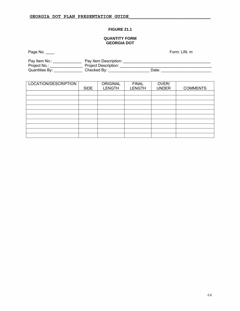
GEORGIA DOT PLAN PRESENTATION GUIDE_____________________________
64
FIGURE 21.1
QUANTITY FORM
GEORGIA DOT
Page No. ____ Form: LIN. m Pay Item No.: _____________ Pay Item Description: ________________________________________ Project No.: _______________ Project Description: __________________________________________ Quantities By: _____________ Checked By: ___________________ Date: _______________________ LOCATION/DESCRIPTION
SIDE ORIGINAL LENGTH
FINAL LENGTH
OVER/ UNDER
COMMENTS
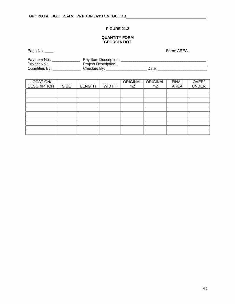
GEORGIA DOT PLAN PRESENTATION GUIDE_____________________________
65
FIGURE 21.2
QUANTITY FORM
GEORGIA DOT
Page No. ____ Form: AREA Pay Item No.: _____________ Pay Item Description: ________________________________________ Project No.: _______________ Project Description: __________________________________________ Quantities By: _____________ Checked By: ___________________ Date: _______________________
LOCATION/ DESCRIPTION
SIDE
LENGTH
WIDTH
ORIGINAL m2
ORIGINAL m2
FINAL AREA
OVER/ UNDER

GEORGIA DOT PLAN PRESENTATION GUIDE_____________________________
66
FIGURE 21.3
QUANTITY FORM
GEORGIA DOT
Page No. ____ Form: MG Pay Item No.: _____________ Pay Item Description: ________________________________________ Project No.: _______________ Project Description: __________________________________________ Quantities By: _____________ Checked By: ___________________ Date: _______________________
LOCATION/ DESCRIPTION
DEPTH
LENGTH
WIDTH
SPREAD
ORIGINAL MG
FINAL MG
OVER/ UNDER

GEORGIA DOT PLAN PRESENTATION GUIDE_____________________________
67
FIGURE 21.4
QUANTITY FORM GEORGIA DOT
Page No. ____ Form: LS/m3/KG Pay Item No.: _____________ Pay Item Description: ________________________________________ Project No.: _______________ Project Description: __________________________________________ Quantities By: _____________ Checked By: ___________________ Date: _______________________
LOCATION/ DESCRIPTION
SIDE
LUMP SUM
ORIGINAL m3
FINAL m3
ORIGINAL kg
FINAL kg
OVER/ UNDER

GEORGIA DOT PLAN PRESENTATION GUIDE_____________________________
68
FIGURE 21.5
QUANTITY FORM
GEORGIA DOT
Page No. ____ Form: LITERS Pay Item No.: _____________ Pay Item Description: ________________________________________ Project No.: _______________ Project Description: __________________________________________ Quantities By: _____________ Checked By: ___________________ Date: _______________________
LOCATION/ DESCRIPTION
LAYERS
LENGTH
WIDTH
SPREAD RATE
ORIGINAL LITERS
FINAL LITERS
OVER/ UNDER

GEORGIA DOT PLAN PRESENTATION GUIDE_____________________________
69
FIGURE 21.6
QUANTITY FORM
GEORGIA DOT
Page No. ____ Form: EACH Pay Item No.: _____________ Pay Item Description: ________________________________________ Project No.: _______________ Project Description: __________________________________________ Quantities By: _____________ Checked By: ___________________ Date: _______________________
LOCATION/ DESCRIPTION
SIDE
ORIGINAL NUMBER
FINAL NUMBER
OVER/ UNDER
COMMENTS
Notes for explanation of over/under runs:___________________________________________________ ____________________________________________________________________________________

GEORGIA DOT PLAN PRESENTATION GUIDE_____________________________
70
CHAPTER 22
CHECKLISTS GENERAL Use checklists to ensure the completeness of the design and to ensure the designer's intent is properly represented. Checklists should be utilized not only for formal or intermediate submittals but throughout the design process. Included herein are examples of checklists that could be used. These checklists are abbreviated versions of more extensive checklists used by various offices within the Department. It is recommended that the designer utilize these checklists as a reminder of the design criteria and performance requirements established at the initiation of each project and/or included in the contract for services. The goal of the plans production team shall be to produce a set of plans for construction that is of high quality and contains "ZERO DEFECTS." Using checklists in conjunction with a standard checking procedure will minimize production costs and reduce technical problems, construction supplemental agreements and the occurrence of liability claims. "The maximum economy is achieved when errors are prevented during production instead of being caught during review."¹ "Project quality is built-in not added on. It is the direct result of careful, properly sequenced production of development and continuous production checking of each work element by the Responsible Professional."¹ Use a standard check and balance checking procedure, similar to the one described below, to ensure that a quality set of plans for construction is produced by the plans production team. UCompletionU - Responsible Professionals check all work for errors and omissions at substantial completion UCheckingU - Quality Reviewers/Checkers, qualified to be Responsible Professionals, check all work (yellow - correct, red - revision) UConcurrenceU - Responsible Professionals backcheck comments for concurrence (red check for OK or X-out for disagree) UIncorporationU - Revisions incorporated by designer or technician (red marks highlighted yellow) UVerificationU - Quality Reviewers/Checkers verify incorporation of revisions (green check) ¹Florida DOT "Quality Initiative Managing Quality" prepared by Post, Buckley, Schuh and Jernigan, Inc. in conjunction with the Florida DOT.

GEORGIA DOT PLAN PRESENTATION GUIDE_____________________________
71
CONCEPT CHECKLIST (Activities usually performed by the Department)
□ Field inspect the project and videotape the project limits □ Request previously prepared plans, concept photos, tax maps (itemized), accident reports, traffic data and Purpose and Need Statement □ Analyze traffic capacity □ Prepare concept typical sections □ Establish design criteria from AASHTO or the Department □ Prepare concept layout or alternates □ Announce and conduct the Concept Meeting □ Invite utilities, regulatory agencies and the local government representatives from applicable offices □ Request preliminary UST investigation □ Conduct the Concept Meeting and prepare meeting minutes □ Revise the Concept Layout as needed □ Request right-of-way cost estimate, utility cost, final UST investigation, and permit investigation □ Prepare and submit the Concept Report and request approvals

GEORGIA DOT PLAN PRESENTATION GUIDE_____________________________
72
DATA BASE PREPARATION CHECKLIST □ Existing property lines □ Property owners □ Plats and deeds for all property owners affected by the project □ Location, top elevation and invert elevations of all existing drainage structures □ Size of all existing box culverts and pipes □ Drainage area survey (as required) □ Locate and identify all known utility facilities □ Establish survey centerlines (baselines) for all roadways, ramps, and driveways □ Station survey centerlines (painting) □ Profile all roadways and driveways □ Cross sections □ Monumentation and control from USC and G □ Monumentation and control set by surveyor □ Stake required right-of-way and easements Base Plan Sheets: □ Existing right-of-way and limits of access □ Existing property corners □ Existing property lines □ Property owners □ Survey control points □ Existing drainage □ Existing topography, drives, roads, etc. □ Existing profiles

GEORGIA DOT PLAN PRESENTATION GUIDE_____________________________
73
PRELIMINARY PLANS DESIGN CHECKLIST
□ Assemble all required design manuals and guides □ Develop typical sections; check clear zone and safety slope requirements □ Set horizontal alignment; use design criteria established for maximum/minimum grades □ Set vertical alignment; use design criteria established for maximum/minimum grades □ Determine lane lengths at intersections □ Establish radii at intersecting roadways □ Determine taper and flare lengths □ Determine driveway and intersection roadway widths □ Request or develop bridge layouts (if required) □ Request existing utilities confirmation □ Develop cross-sections □ Design drainage using the Department's Drainage Manual □ Design Erosion and Sediment Control using the State Soil and Water Conservation Commission's Manual for Erosion and Sediment Control in Georgia □ Develop retaining wall or special slope support (as required) □ Set right-of-way and easements; check for appropriate setbacks from construction limits □ Develop stage construction and detours □ Request floodplain and environmental permits □ Request and conduct Preliminary Field Plan Review (PFPR) □ Respond to PFPR Report comments □ Complete, submit, and revise right-of-way plans □ Complete preliminary plans □ Prepare Preliminary Special Provisions

FINAL PLANS DESIGN CHECKLIST
□ Receive soils report and pavement recommendation s
relocated utilities plans
way plans (see Construction Plans Assembly sequencing)
□ rainage design
□ rosion and Sediment Control plans
□ in plans by others (as appropriate)
o Signing and pavement markings o Utilities
Prepare quantities summaries
Prepare detailed estimate
Write special provisions
Request and hold Final Field Plan Review (FFPR)
Respond to FFPR Report
Complete and submit Final Plans
Submit earthwork and drainage calculations
74
□ Receive Bridge Layouts and Railroad Approval
□ ications and Complete existing utilities verif
□ Design the pavement sections and obtain approval
□ Revise profiles and alignments if required
□ Complete the typical sections
□ Complete the road
Complete the d
Complete the E
Develop construction details
□ Complete plans or receive/obta
o Landscape o Lighting o Walls o Bridges o Signals
□□□□□□□

GEORGIA DOT PLAN PRESENTATION GUIDE_____________________________
75
PRELIMINARY PLANS PREPARATION CHECKLIST COVER SHEET □ Location Sketch □ North Arrow □ Graphic Scale □ Project Number, Federal Route Number, State Route Number, Georgia DOT PI Number □ County or Counties □ Index and General Notes (if possible) □ Design Data □ Length of Project Box □ Date of Completion □ Signatures □ Routine Notes INDEX □ Drawing Numbers □ Descriptions □ Sheet Numbers □ Appropriate Department Standards Listed □ Appropriate Construction Details Listed □ Department's Standards/Construction Details up to Date TYPICAL SECTIONS □ Template Dimensions □ Pavement Thicknesses □ Slopes - Pavement, Median, Shoulder, Cut and Fill □ Special Conditions □ Clear Zone PLAN SHEETS □ Existing Topography and Planimetrics □ Existing Right-Of-Way and Limits of Access □ Property Lines and Owner's Name □ Land Lot Numbers □ Centerline Construction and Stationing □ Curve Data □ Edges of Pavements □ Back of Curbs □ Sidewalk/Wheelchair Ramp Locations □ Proposed Right-Of-Way and Limits of Access □ Label Begin and End of Project, Bridges and Exceptions □ Label P.C.'s and P.T.'s of Curves □ Place 20m and 100m Tick Marks □ Label 100m Tick Marks □ Label Cross Streets □ Matchlines □ North Arrow □ Coordinate Grid □ Graphic Scale □ Title Block □ Drawing Numbers □ Project Number □ Station Equations □ Angles and Intersection Equalities

GEORGIA DOT PLAN PRESENTATION GUIDE_____________________________
76
□ Station Curb Radius Returns and Dimension Radii □ Median Openings □ Pavement Dimensions □ Flares and Tapers □ Superelevations □ Right-of-Way Ties □ Construction Limits □ Major Drainage and Right-Of-Way Blockouts □ Limits of Cross Street Construction □ Control Points

GEORGIA DOT PLAN PRESENTATION GUIDE_____________________________
77
ROADWAY PROFILES □ Begin and End Project Stations □ Begin and End Bridge Stations □ PVC, PVT, and PVI of Vertical Curves □ Vertical Curve Data □ Equalities □ Existing and Proposed Groundlines □ Proposed Elevations □ Grades between PVI's □ Vertical Elevation Datum □ Applicable Notes (feather asphalt, remove pavement limits, etc.) DRAINAGE AREA MAP AND DRAINAGE PROFILES Drainage Area Map □ Project Centerline with Stationing □ Existing Roads and Streets Shown and Labeled □ Existing Culverts and Data (Areas, Flows, Etc.) □ Ridge Lines and Direction of Flow □ Drainage Areas □ North Arrow and Graphic Scale □ Proposed Culverts and Data (Areas, Flows, Etc.) Major Culvert Profiles □ Location of Structures - Station and Offset □ Structure Number □ Structure Type □ Invert Elevations □ Length of Culvert - Measured along Centerline of Culvert □ Slope of Culvert CROSS SECTIONS Check for Each Roadway: □ Mainline □ Cross Streets □ Stage Construction □ Scale □ Existing Groundline □ Proposed Template (Finish grade and subgrade) □ Profile Grade Elevation □ Centerline Identifiable □ Station Numbers □ Ditches Shown (Elevations may be required for special ditches) □ Right-of-way or Easement limits PRELIMINARY WALL LAYOUT Plan View □ North Arrow; Baseline Beginning and Ending Wall Stations and Offsets □ Stations and Offsets at Wall Break Points and 50' Stations Along Alignment □ Limits of Right of Way/Easement by Station and Offset □ Bearing of Tangent alignments; PC's and PT's of Curved alignments □ Alignments of Utilities; Limits of Right of Way; Construction Easements, if any
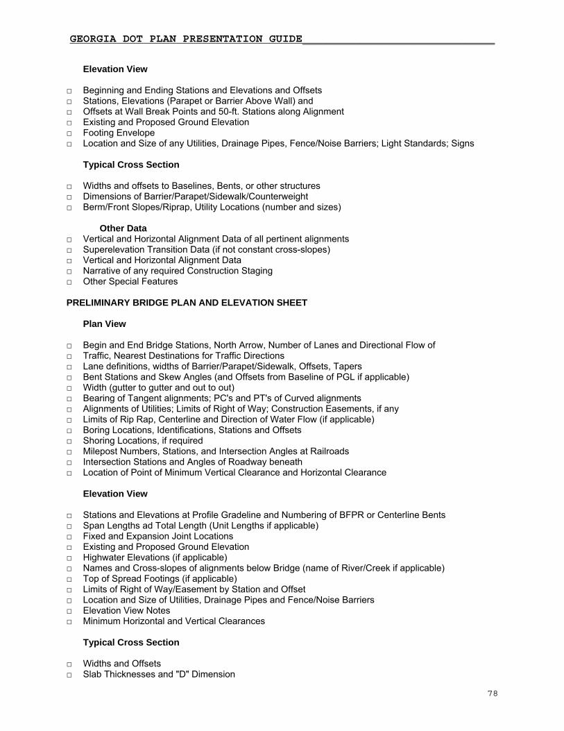
GEORGIA DOT PLAN PRESENTATION GUIDE_____________________________
78
Elevation View □ Beginning and Ending Stations and Elevations and Offsets □ Stations, Elevations (Parapet or Barrier Above Wall) and □ Offsets at Wall Break Points and 50-ft. Stations along Alignment □ Existing and Proposed Ground Elevation □ Footing Envelope □ Location and Size of any Utilities, Drainage Pipes, Fence/Noise Barriers; Light Standards; Signs Typical Cross Section □ Widths and offsets to Baselines, Bents, or other structures □ Dimensions of Barrier/Parapet/Sidewalk/Counterweight □ Berm/Front Slopes/Riprap, Utility Locations (number and sizes) Other Data □ Vertical and Horizontal Alignment Data of all pertinent alignments □ Superelevation Transition Data (if not constant cross-slopes) □ Vertical and Horizontal Alignment Data □ Narrative of any required Construction Staging □ Other Special Features PRELIMINARY BRIDGE PLAN AND ELEVATION SHEET Plan View □ Begin and End Bridge Stations, North Arrow, Number of Lanes and Directional Flow of □ Traffic, Nearest Destinations for Traffic Directions □ Lane definitions, widths of Barrier/Parapet/Sidewalk, Offsets, Tapers □ Bent Stations and Skew Angles (and Offsets from Baseline of PGL if applicable) □ Width (gutter to gutter and out to out) □ Bearing of Tangent alignments; PC's and PT's of Curved alignments □ Alignments of Utilities; Limits of Right of Way; Construction Easements, if any □ Limits of Rip Rap, Centerline and Direction of Water Flow (if applicable) □ Boring Locations, Identifications, Stations and Offsets □ Shoring Locations, if required □ Milepost Numbers, Stations, and Intersection Angles at Railroads □ Intersection Stations and Angles of Roadway beneath □ Location of Point of Minimum Vertical Clearance and Horizontal Clearance Elevation View
□ Stations and Elevations at Profile Gradeline and Numbering of BFPR or Centerline Bents □ Span Lengths ad Total Length (Unit Lengths if applicable) □ Fixed and Expansion Joint Locations □ Existing and Proposed Ground Elevation □ Highwater Elevations (if applicable) □ Names and Cross-slopes of alignments below Bridge (name of River/Creek if applicable) □ Top of Spread Footings (if applicable) □ Limits of Right of Way/Easement by Station and Offset □ Location and Size of Utilities, Drainage Pipes and Fence/Noise Barriers □ Elevation View Notes □ Minimum Horizontal and Vertical Clearances Typical Cross Section □ Widths and Offsets □ Slab Thicknesses and "D" Dimension

GEORGIA DOT PLAN PRESENTATION GUIDE_____________________________
79
□ Supporting Beam/Girder Size/Depth; Fascia Girders □ Beam/Girder Spacings and Overhangs □ Utility Locations (number and sizes) □ Sequence of Construction (if applicable) Other Data □ Vertical and Horizontal Alignment Data of all pertinent alignments □ Superelevation Transition Data (if not constant cross-slopes) □ General Notes □ Design Data □ Number and Size of Utilities and Owners □ "Bridge Consists of….." Data □ Hydrology Data (if applicable) □ Existing Bridge Serial Number, I.D. Number, Project P.I. Number and □ Bridge Number above Title Box
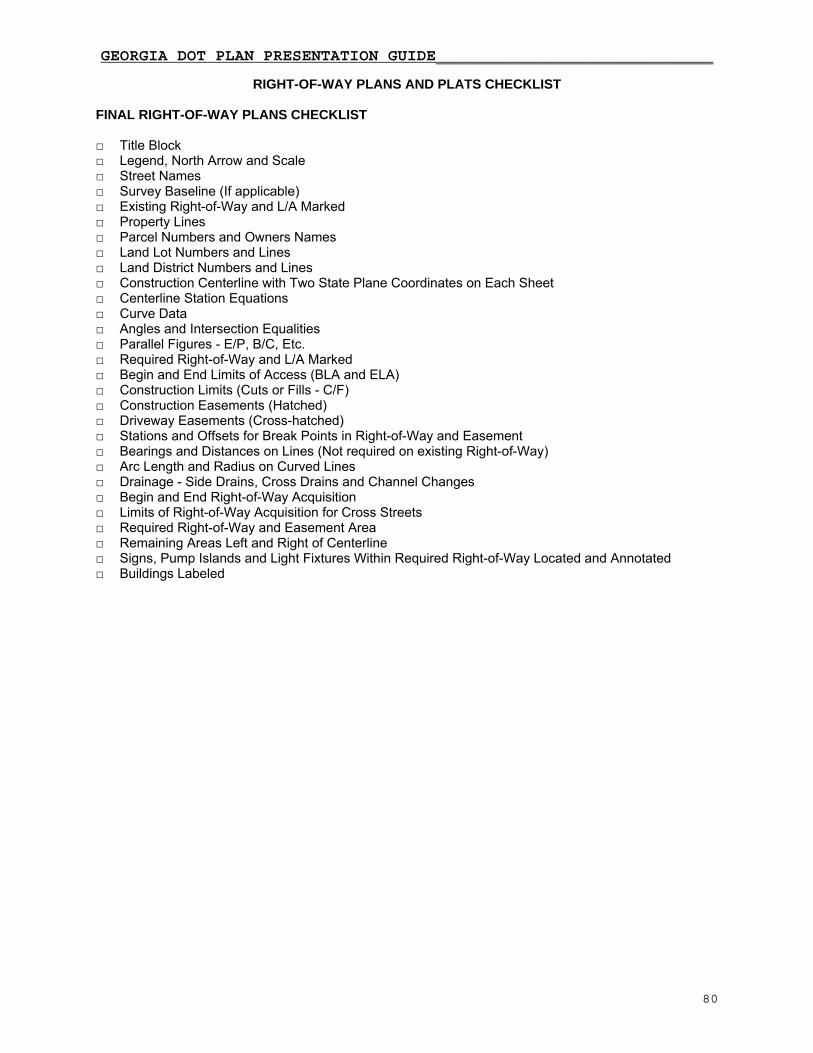
GEORGIA DOT PLAN PRESENTATION GUIDE_____________________________
80
RIGHT-OF-WAY PLANS AND PLATS CHECKLIST FINAL RIGHT-OF-WAY PLANS CHECKLIST □ Title Block □ Legend, North Arrow and Scale □ Street Names □ Survey Baseline (If applicable) □ Existing Right-of-Way and L/A Marked □ Property Lines □ Parcel Numbers and Owners Names □ Land Lot Numbers and Lines □ Land District Numbers and Lines □ Construction Centerline with Two State Plane Coordinates on Each Sheet □ Centerline Station Equations □ Curve Data □ Angles and Intersection Equalities □ Parallel Figures - E/P, B/C, Etc. □ Required Right-of-Way and L/A Marked □ Begin and End Limits of Access (BLA and ELA) □ Construction Limits (Cuts or Fills - C/F) □ Construction Easements (Hatched) □ Driveway Easements (Cross-hatched) □ Stations and Offsets for Break Points in Right-of-Way and Easement □ Bearings and Distances on Lines (Not required on existing Right-of-Way) □ Arc Length and Radius on Curved Lines □ Drainage - Side Drains, Cross Drains and Channel Changes □ Begin and End Right-of-Way Acquisition □ Limits of Right-of-Way Acquisition for Cross Streets □ Required Right-of-Way and Easement Area □ Remaining Areas Left and Right of Centerline □ Signs, Pump Islands and Light Fixtures Within Required Right-of-Way Located and Annotated □ Buildings Labeled

GEORGIA DOT PLAN PRESENTATION GUIDE_____________________________
81
EXHIBIT PLATS (If Required) □ Letter Size □ North Arrow □ Scale (1:500 Typical) □ Parcel Number □ Owners Names □ Structures Labeled □ Access Rights and Breaks □ Dimension of Driveways □ Signs/Fences □ Gas Station - Pumps, Signs, Lights □ Existing and Proposed Right-of-Way □ Required Right-of-Way Area □ Easements Shown and Labeled as to Type □ Required Easement Area □ Stations and Offsets for Break Points □ Source of Property Information (Field Survey, Tax Maps, Deed Book Number and Page) □ Sealed by a Registered Land Surveyor in the State of Georgia □ Metes and Bounds on All Lines and Arcs Defining Right-of-Way and Permanent Easements (Arc length and radius on arcs, bearing and distance on lines.)
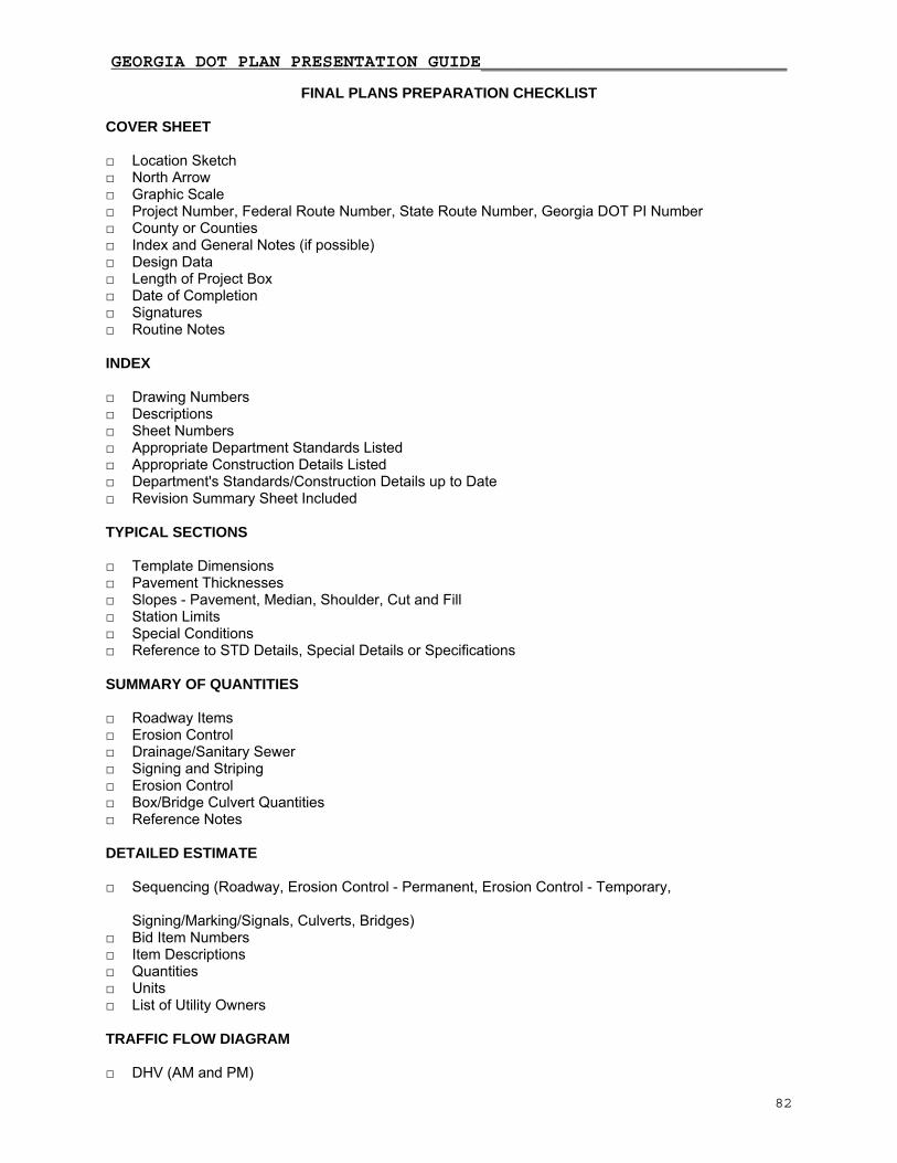
GEORGIA DOT PLAN PRESENTATION GUIDE_____________________________
82
FINAL PLANS PREPARATION CHECKLIST COVER SHEET □ Location Sketch □ North Arrow □ Graphic Scale □ Project Number, Federal Route Number, State Route Number, Georgia DOT PI Number □ County or Counties □ Index and General Notes (if possible) □ Design Data □ Length of Project Box □ Date of Completion □ Signatures □ Routine Notes INDEX □ Drawing Numbers □ Descriptions □ Sheet Numbers □ Appropriate Department Standards Listed □ Appropriate Construction Details Listed □ Department's Standards/Construction Details up to Date □ Revision Summary Sheet Included TYPICAL SECTIONS □ Template Dimensions □ Pavement Thicknesses □ Slopes - Pavement, Median, Shoulder, Cut and Fill □ Station Limits □ Special Conditions □ Reference to STD Details, Special Details or Specifications SUMMARY OF QUANTITIES □ Roadway Items □ Erosion Control □ Drainage/Sanitary Sewer □ Signing and Striping □ Erosion Control □ Box/Bridge Culvert Quantities □ Reference Notes DETAILED ESTIMATE □ Sequencing (Roadway, Erosion Control - Permanent, Erosion Control - Temporary, Signing/Marking/Signals, Culverts, Bridges) □ Bid Item Numbers □ Item Descriptions □ Quantities □ Units □ List of Utility Owners TRAFFIC FLOW DIAGRAM □ DHV (AM and PM)

GEORGIA DOT PLAN PRESENTATION GUIDE_____________________________
83
□ ADT (AM and PM) CONSTRUCTION LAYOUT/STAKEOUT SHEET (If needed) □ Label Alignments □ Intersection and Offset Equalities □ Label Bearings on Tangents □ Label Curves □ Curve Data □ Project Control Points PLAN SHEETS □ North Arrow □ Coordinate Grid □ Graphic Scale □ Complete Title Block □ Drawing Numbers □ Project Number □ Existing Topography and Planimetrics □ Existing Right-of-Way and Limits of Access □ Property Lines and Owner's Name □ Land Lot Numbers □ Control Points □ Background Clip Limits □ Horizontal Geometry □ Curve Data □ Label Begin and End of Project □ Label Begin and End of Exceptions □ Label Equalities (Stations and Intersections) □ Angles at Intersections □ Bearings on Tangents □ Label P.C.'s and P.T.'s of Curves □ 20m and 100m Tick Marks □ Label 100m Tick Marks □ Label Cross Streets □ Matchlines □ Edges of Pavements □ Back of Curbs □ Pavement Dimensions □ Offsets □ Flares and Tapers □ Superelevations and Transitions □ Proposed Right-of-Way and Limits of Access □ Right-of-Way Ties □ Limits of Cross Street Construction □ Intersection Details □ Intersection Equalities □ Curb Radii and Return Points □ Median Openings □ Construction Limits □ Guardrail (Location and Type) □ Guardrail Anchorages (Location and Type) □ Begin and End Bridges □ Approach Slabs □ Special Grading

GEORGIA DOT PLAN PRESENTATION GUIDE_____________________________
84
Drainage □ Major Culverts (Location and Size) □ Culvert End Treatments and Erosion Protection □ Catch Basins-Drop Inlets (Location and Type) □ Side Drain Pipes Drainage Ditches (Location and Elevation) □ Cut Ditches □ Cut off Ditches □ Toe Ditches □ Special Ditches (Ponding Water) ROADWAY PROFILES □ Begin and End Project Stations □ Begin and End Bridge Stations □ PVC, PVT, and PVI of Vertical Curves □ Vertical Curve Data □ Equalities □ Existing and Proposed Groundlines □ Proposed Elevations □ Grades Between PVI's □ Vertical Elevation Datum □ Speed Designs for All Vertical Curves INTERSECTION DETAILS □ North Arrow □ Graphic Scale □ Roadway Geometrics □ Dimensions □ Radii Labeled □ Offsets □ Stations on Radius Returns □ Limits of Construction □ Drainage □ Utilities □ Flares and Tapers □ Grading/Contouring of Pavement (If required) DRAINAGE AREA MAP AND DRAINAGE/SEWER PROFILES Drainage Area Map □ Project Centerline with Stationing □ Existing Roads and Streets □ Existing Culverts and Data (Areas, Flows, etc.) □ Ridge Lines and Direction of Flow □ Drainage Areas □ North Arrow and Graphic Scale □ Proposed Culverts and Data (Areas, Flows, etc.) Profiles □ Location of Structures - Station and Offset □ Structure Number □ Structure Type

GEORGIA DOT PLAN PRESENTATION GUIDE_____________________________
85
□ Invert Elevations □ Length of Pipe/Culvert - Measured along Centerline of Pipe/Culvert □ Slope of Pipe/Culvert MAINTENANCE OF TRAFFIC PLANS □ Roadway Plan Sheet Requirements - Street Names, Pavements, Etc. □ Legend (See Standard Legend) □ Suggested Sequence of Construction □ Existing Travelway □ Current Stage Construction □ Completed Construction □ Stage Construction Cross Sections □ Earthwork by Stage □ Construction Signing □ Channelizing Devices □ Temporary Barricades UTILITY PLANS □ Legend (See Standard Legend) □ Existing Topography and Planimetrics □ Proposed Planimetrics and Curve Data □ Existing and Proposed Drainage □ Existing and Relocated Gas □ Existing and Relocated Power □ Existing and Relocated Water and Sewer □ Existing and Relocated Telephone □ Existing and Relocated Cable Television □ Existing and Proposed Drainage Structures □ Utilities on Bridges SIGNING AND MARKING PLANS □ Legend and General Notes □ Lane Designations - Pavement Markings □ Sidewalks/Handicap Ramps □ Guardrail □ Right-of-Way □ Flashers □ Identify Public Roads and Major Development Driveways □ Stop Bars □ Turn Arrows □ Striped out Areas □ Raised Pavement Markers □ Signing SIGNALIZATION PLANS □ North Arrow □ Graphic Scale □ Roadway Geometrics □ Intersection Equality Stations □ Utilities □ Lighting □ Drainage □ Signal Pole/Mast Arm Locations □ Type and Location of Loops □ Type and Location of Signal Heads

GEORGIA DOT PLAN PRESENTATION GUIDE_____________________________
86
□ Pedestrian Signal (If required) □ Stop Bars □ Cross Walks □ Striping □ Signal Phasing LIGHTING PLANS (with applicable details) EROSION AND SEDIMENT CONTROL □ Grass □ Bituminous Treated Glass Fiber Mulch □ Permanent Soil Reinforcing Mat □ Pavement or Rip Rap □ Other CROSS SECTIONS Check For Each Roadway: □ Mainline □ Cross Streets □ Stage Construction □ Cross Section Pattern Sheet (Interchanges) □ Scale □ Existing Groundline □ Proposed Template (Finish Grade and Subgrade) □ Profile Grade Elevation □ Centerline Identifiable □ Station Numbers □ Ditches Shown (Elevations may be required for special ditches.) CONSTRUCTION DETAILS □ Dimensions □ Measurement and Payment SPECIAL DESIGN CULVERTS DEPARTMENT STANDARDS □ Latest Version □ Comprehensive Review WALL PLANS □ Begin/End Stations □ Elevations at Begin, End, and Break Points □ Existing Ground □ Proposed Grade □ Right-of-Way and Easement Limits □ Superelevation Data □ Stations and Offsets to Face of Wall □ Noise Wall Requirements (If Applicable) □ Overhead Signs □ Drainage structures □ Roadway Lighting □ Sequence of Wall Construction and Staging (If Required) □ Length of Mesh and Panel Details for Earth Type Walls
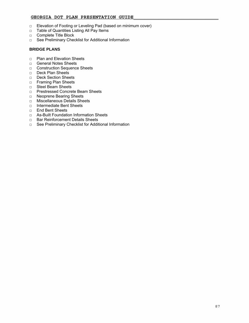
GEORGIA DOT PLAN PRESENTATION GUIDE_____________________________
87
□ Elevation of Footing or Leveling Pad (based on minimum cover) □ Table of Quantities Listing All Pay Items □ Complete Title Block □ See Preliminary Checklist for Additional Information BRIDGE PLANS □ Plan and Elevation Sheets □ General Notes Sheets □ Construction Sequence Sheets □ Deck Plan Sheets □ Deck Section Sheets □ Framing Plan Sheets □ Steel Beam Sheets □ Prestressed Concrete Beam Sheets □ Neoprene Bearing Sheets □ Miscellaneous Details Sheets □ Intermediate Bent Sheets □ End Bent Sheets □ As-Built Foundation Information Sheets □ Bar Reinforcement Details Sheets □ See Preliminary Checklist for Additional Information

GEORGIA DOT PLAN PRESENTATION GUIDE_____________________________
88
FIELD PLAN REVIEW CHECKLIST GENERAL
ο Review design and construction schedule for feasibility.
ο Will selective clearing and grubbing be required?
ο Can large trees or landscaped areas including decorative walls be preserved by design alterations?
ο Verify begin and end project stations.
ο Does project require permitting/coordination with the Department for work within state rights-of-way?
ο Is a USACOE 404 permit required?
ο Have cultural resources been addressed?
ο Have efforts been made to reduce impacts to wetlands and/or cultural resources?
ο If a Pre-discharge Notification is required, this should be submitted to the COE as soon as the preliminary plans have been approved.
ο List utility owners and any known conflicts.
ο Check side street returns and width of side streets. Side streets should match existing width at final tie-in.
ο Check locations of driveways. Note driveways where design alterations could avoid impacts to landscaping or large trees.
ο Where will sidewalks be provided?
ο Review median opening locations. Provide additional pavement widening where required.
ο Are cul-de-sacs shown for existing roads which are to be terminated? Do cul-de-sacs provide area for fire trucks to turn around? Consider proper end delineation (barricades or guardrail).
ο Would the use of retaining walls in some locations provide a reduction of impacts to properties with an overall cost savings to the Department?
ο Are there any parcels which have special access requirements such as for large trucks, tractors, and/or trailers?
ο Is special earthwork required, such as removing stockpiled dirt, sanitary landfills, or undercut of undesirable soils?
ο Do any signs or road markers require stockpiling by the contractor? Other salvageable material?
ο Has existing topography been field verified? Has the plan preparer provided adequate evidence that the topography shown on the plans is a reasonable representation of actual conditions?
ο Review parcels with existing fences. Disposition of fences must be determined before appraisals are done.
ο Has note for wheelchair ramps been included?
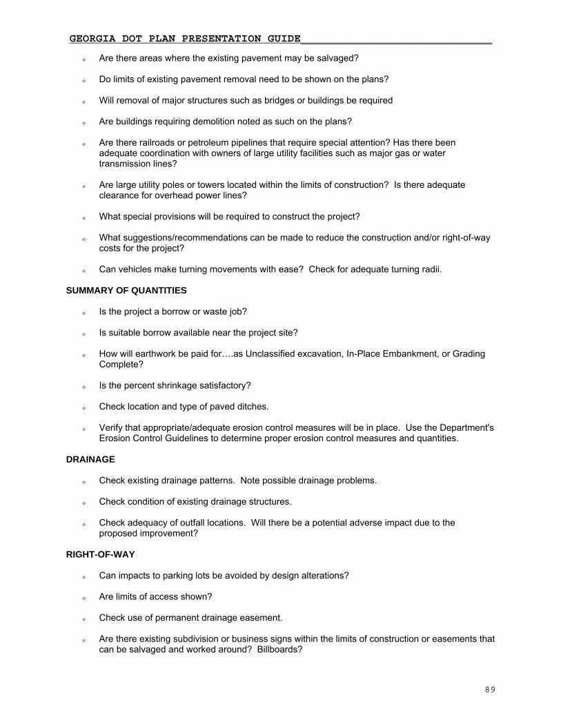
GEORGIA DOT PLAN PRESENTATION GUIDE_____________________________
89
ο Are there areas where the existing pavement may be salvaged?
ο Do limits of existing pavement removal need to be shown on the plans?
ο Will removal of major structures such as bridges or buildings be required
ο Are buildings requiring demolition noted as such on the plans?
ο Are there railroads or petroleum pipelines that require special attention? Has there been adequate coordination with owners of large utility facilities such as major gas or water transmission lines?
ο Are large utility poles or towers located within the limits of construction? Is there adequate clearance for overhead power lines?
ο What special provisions will be required to construct the project?
ο What suggestions/recommendations can be made to reduce the construction and/or right-of-way costs for the project?
ο Can vehicles make turning movements with ease? Check for adequate turning radii. SUMMARY OF QUANTITIES
ο Is the project a borrow or waste job?
ο Is suitable borrow available near the project site?
ο How will earthwork be paid for….as Unclassified excavation, In-Place Embankment, or Grading Complete?
ο Is the percent shrinkage satisfactory?
ο Check location and type of paved ditches.
ο Verify that appropriate/adequate erosion control measures will be in place. Use the Department's
Erosion Control Guidelines to determine proper erosion control measures and quantities. DRAINAGE
ο Check existing drainage patterns. Note possible drainage problems.
ο Check condition of existing drainage structures.
ο Check adequacy of outfall locations. Will there be a potential adverse impact due to the proposed improvement?
RIGHT-OF-WAY
ο Can impacts to parking lots be avoided by design alterations?
ο Are limits of access shown?
ο Check use of permanent drainage easement.
ο Are there existing subdivision or business signs within the limits of construction or easements that can be salvaged and worked around? Billboards?

GEORGIA DOT PLAN PRESENTATION GUIDE_____________________________
90
ο Are there improvements located within the required right-of-way? Could the design be altered to reduce or avoid impacts?
ο Is there fenced livestock within the limits of construction? How will livestock be contained during
construction? Temporary fence?
ο Is there evidence of major petroleum pipelines within the project limits?
ο Are septic tanks or underground storage tanks located within the proposed right-of-way or construction easements?
ο Are any properties likely to be total takes? Will relocation assistance be required?
MAINTENANCE OF TRAFFIC
ο How will traffic be maintained during construction?
ο Can traffic be detoured using local streets rather than an on-site detour?

FIELD PLAN REVIEW CHECKLIST
APPENDIX Sample Metric Plan Set
APPENDIX Images Cover Sheet Drainage Area 1 Drainage Area 2 Drainage Section 1 Drainage Section 2 Erosion 1 Erosion 2 Cross Section Earthwork 1 Cross Section Earthwork 2 Profile 1 Profile 2 Plan 1 Plan 2 Typical Section 1 Typical Section 2 Crossroad 1 Crossroad 2 91