power xpert® cx - 伊顿,全球商业动力之源pub/@eatoncnes/documents/... · iec 61439-1:...
TRANSCRIPT

Power Xpert® CX
IEC Low Voltage Motor Control and Power Distribution Center
6069511 G01 01
User manual
Power Xpert CX
Low voltage switchgear
Operations consisting of installing, connecting, operating, checking, commissioning, decommissioning and maintaining
low-voltage switchgear of the Power Xpert CX type must only be carried out by authorised personnel.
Eaton Industries (Netherlands) B.V.
Europalaan 202, 7559 SC
P.O. Box 23, 7550 AA
Hengelo, the Netherlands

Power Xpert® CX
User Manual PowerXpert® CX - 6069511 G01 01 2
CONTENTS
1 Introduction ....................................................................................................................................................... 6
1.1 General system description ................................................................................................................................... 6
1.1.1 System type ................................................................................................................................................... 6
1.1.2 System construction ...................................................................................................................................... 6
1.1.3 Options .......................................................................................................................................................... 6
1.2 USING THE MANUAL .............................................................................................................................................. 7
1.2.1 Target group .................................................................................................................................................. 7
1.2.2 Structure of the manual ................................................................................................................................ 7
2 Safety instructions .............................................................................................................................................. 8
2.1 General instructions............................................................................................................................................... 8
2.1.1 Personnel ...................................................................................................................................................... 8
2.1.2 Safety of bystanders ...................................................................................................................................... 8
2.1.3 Safety plan..................................................................................................................................................... 8
2.1.4 Safety standards ............................................................................................................................................ 8
2.2 Safety of the switch room ...................................................................................................................................... 8
2.2.1 Clear space .................................................................................................................................................... 8
2.2.2 Height ............................................................................................................................................................ 8
2.2.3 Escape routes ................................................................................................................................................ 9
2.2.4 Entrances..................................................................................................................................................... 10
2.2.5 Storage of (spare) materials ........................................................................................................................ 10
2.2.6 Availability of extinguishers ........................................................................................................................ 10
2.2.7 Notation guide ............................................................................................................................................ 10
2.2.8 What to do in the event of a fire ................................................................................................................. 10

Power Xpert® CX
User Manual PowerXpert® CX - 6069511 G01 01 3
3 Product description .......................................................................................................................................... 11
3.1 The system ........................................................................................................................................................... 11
3.1.1 Panels .......................................................................................................................................................... 11
3.1.2 Panel Dimensions ........................................................................................................................................ 12
3.1.3 Feeder Panels .............................................................................................................................................. 13
3.1.4 Withdrawable Panels .................................................................................................................................. 14
3.1.5 Withdrawable units ..................................................................................................................................... 14
3.1.6 Withdrawable units: Dimensions ................................................................................................................ 15
3.1.7 Setting or adjusting the protection level .................................................................................................... 16
3.1.8 Adjusting the earth fault protection relay .................................................................................................. 16
3.2 Busbar Systems .................................................................................................................................................... 17
3.2.1 Horizontal Busbar System ........................................................................................................................... 17
3.2.2 Vertical Busbar System ............................................................................................................................... 18
3.2.3 Protective and neutral conductor bars ....................................................................................................... 18
3.2.4 Busbar Supports .......................................................................................................................................... 18
3.2.5 Short Circuit Ratings .................................................................................................................................... 19
3.3 Cable Entry and connection for incoming and outgoing feeders ........................................................................ 19
3.3.1 Feeder Columns .......................................................................................................................................... 19
3.3.2 Withdrawable Units .................................................................................................................................... 19
3.3.3 Fixed Units ................................................................................................................................................... 20
3.4 Safety features ..................................................................................................................................................... 20
3.4.1 Execution of work ....................................................................................................................................... 20
3.5 General technical data ......................................................................................................................................... 21
3.5.1 Electrical data .............................................................................................................................................. 21
3.5.2 Environmental conditions ........................................................................................................................... 22
3.5.3 Busbar cross sections and panel dimensions .............................................................................................. 23
3.6 Connection possibilities and ranges .................................................................................................................... 24
3.6.1 Cubicles with an incoming or one outgoing feeder .................................................................................... 24
3.6.2 Compartments with draw-out units ........................................................................................................... 24
Power Xpert® CX
User Manual PowerXpert® CX - 6069511 G01 01 4
4 System assembly .............................................................................................................................................. 26
4.1 Environmental requirements ............................................................................................................................... 26
4.1.1 Climate ........................................................................................................................................................ 26
4.1.2 Room for extension ..................................................................................................................................... 26
4.1.3 Floor ............................................................................................................................................................ 26
4.1.4 Floor plan .................................................................................................................................................... 26
4.1.5 During transport and storage ...................................................................................................................... 26
4.2 System transport ................................................................................................................................................. 28
4.2.1 Delivery inspection ...................................................................................................................................... 28
4.2.2 Instructions for transport ............................................................................................................................ 28
4.2.3 Transport in the operating area .................................................................................................................. 29
4.2.4 Installation of a Switchboard ...................................................................................................................... 29
4.2.5 Unpacking the delivery ............................................................................................................................... 30
4.2.6 Inspection of the floor ................................................................................................................................. 30
4.3 Coupling of the panels ......................................................................................................................................... 30
4.4 Coupling of the busbars ....................................................................................................................................... 31
4.5 Connection of wiring and cables .......................................................................................................................... 32
4.5.1 Connecting a main power cable to the withdrawable unit ......................................................................... 32
4.5.2 Connecting the auxiliary cables to the withdrawable unit ......................................................................... 32
4.5.3 Connection of main power cable to the air circuit breaker ........................................................................ 32
5 System operation ............................................................................................................................................. 33
5.1 Testing ................................................................................................................................................................. 33
5.2 Setting up of Equipment ...................................................................................................................................... 33
5.3 Opening and closing doors and covers ................................................................................................................ 34
5.4 Operation ............................................................................................................................................................. 34
5.4.1 Air Circuit Breakers (ACB) ............................................................................................................................ 34
5.4.2 Moulded Case Circuit Breakers ................................................................................................................... 34
5.4.3 Incoming devices ......................................................................................................................................... 35
5.4.4 Specific Literature and Manuals .................................................................................................................. 35
5.5 Mechanical operation withdrawable units .......................................................................................................... 35
5.5.1 Withdrawable unit positions ....................................................................................................................... 36
5.5.2 Withdrawable unit operation ..................................................................................................................... 37
5.6 Decommissioning ................................................................................................................................................. 38
5.6.1 Dismantling ................................................................................................................................................. 38
5.6.2 Disposal ....................................................................................................................................................... 38

Power Xpert® CX
User Manual PowerXpert® CX - 6069511 G01 01 5
6 System inspection, maintenance and repair ..................................................................................................... 39
6.1 Logbook ............................................................................................................................................................... 39
6.2 Inspection and maintenance, general ................................................................................................................. 39
6.3 Checking and maintenance schedule for components ........................................................................................ 39
6.3.1 Periodic check ............................................................................................................................................. 40
6.3.2 Maintenance ............................................................................................................................................... 40
6.4 Modification......................................................................................................................................................... 40
6.5 Fault diagnosis ..................................................................................................................................................... 40
6.6 Torque Ratings ..................................................................................................................................................... 41
6.6.1 General ........................................................................................................................................................ 41
6.6.2 Han Modular ............................................................................................................................................... 41
6.6.3 Han HC Modular .......................................................................................................................................... 42
6.7 Service-department ............................................................................................................................................. 42
7 Data Outgoing Units ......................................................................................................................................... 43
8 Accessories And Spare Parts ............................................................................................................................. 48
8.1 List of available accessories and spare parts ....................................................................................................... 48
8.1.1 Structures .................................................................................................................................................... 48
8.1.2 Withdrawable Units .................................................................................................................................... 48
9 Appendix .......................................................................................................................................................... 49
9.1 General ................................................................................................................................................................ 49
10 Comment form ................................................................................................................................................. 50
Power Xpert® CX
User Manual PowerXpert® CX - 6069511 G01 01 6
1 Introduction
1.1 General system description
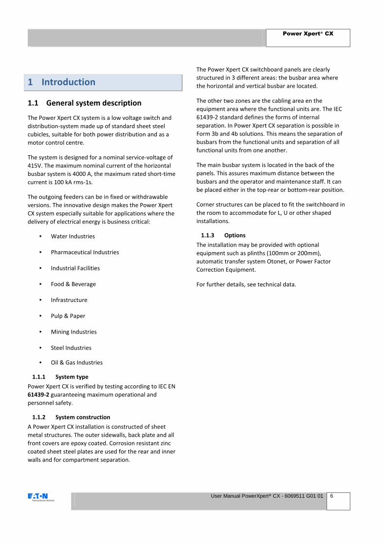
The Power Xpert CX system is a low voltage switch and
distribution-system made up of standard sheet steel
cubicles, suitable for both power distribution and as a
motor control centre.
The system is designed for a nominal service-voltage of
415V. The maximum nominal current of the horizontal
busbar system is 4000 A, the maximum rated short-time
current is 100 kA rms-1s.
The outgoing feeders can be in fixed or withdrawable
versions. The innovative design makes the Power Xpert
CX system especially suitable for applications where the
delivery of electrical energy is business critical:
• Water Industries
• Pharmaceutical Industries
• Industrial Facilities
• Food & Beverage
• Infrastructure
• Pulp & Paper
• Mining Industries
• Steel Industries
• Oil & Gas Industries
1.1.1 System type
Power Xpert CX is verified by testing according to IEC EN
61439-2 guaranteeing maximum operational and
personnel safety.
1.1.2 System construction
A Power Xpert CX installation is constructed of sheet
metal structures. The outer sidewalls, back plate and all
front covers are epoxy coated. Corrosion resistant zinc
coated sheet steel plates are used for the rear and inner
walls and for compartment separation.
The Power Xpert CX switchboard panels are clearly
structured in 3 different areas: the busbar area where
the horizontal and vertical busbar are located.
The other two zones are the cabling area en the
equipment area where the functional units are. The IEC
61439-2 standard defines the forms of internal
separation. In Power Xpert CX separation is possible in
Form 3b and 4b solutions. This means the separation of
busbars from the functional units and separation of all
functional units from one another.
The main busbar system is located in the back of the
panels. This assures maximum distance between the
busbars and the operator and maintenance staff. It can
be placed either in the top-rear or bottom-rear position.
Corner structures can be placed to fit the switchboard in
the room to accommodate for L, U or other shaped
installations.
1.1.3 Options
The installation may be provided with optional
equipment such as plinths (100mm or 200mm),
automatic transfer system Otonet, or Power Factor
Correction Equipment.
For further details, see technical data.

Power Xpert® CX
User Manual PowerXpert® CX - 6069511 G01 01 7
1.2 USING THE MANUAL
1.2.1 Target group
The switchgear is designed for use by personnel who are
expert or adequately trained in using switchgear and/or
carrying out electrical operations.
The information corresponds as closely as possible with
the supplied product. However, due to Eaton's policy of
continual product improvement, it is possible that
certain details will vary.
The information in this manual will guide the user of the
product through all the facets of the operation and the
commissioning and maintenance for which the product
is designed.
The various possibilities, the assembly instructions, and
applications, etc. are however non-binding, serving for
reference purposes.
Eaton products are supplied in accordance with the
general terms and conditions of sale and supply which
have been lodged with the Chambers of Commerce. This
product manual in no way affects these general
conditions.
1.2.2 Structure of the manual
The manual contains 10 chapters.
Chapters 1 and 2 contain general information on the
system design and construction and general safety
aspects. The information is presented in the form of
descriptive texts, supported by illustrations as necessary.
Illustrations are numbered consecutively for each
chapter, and are captioned if necessary.
Chapters 3 to 6 consist mainly of procedures. These
procedures contain step-by-step descriptions of actions
in the order in which they should be carried out.
Illustrations are on the same page as the relevant step
and have the same number as the paragraph.
WARNING
Never take any action without knowing what
effect it will have.
REMARK
Read through all actions first, using the relevant
figures. Contact Eaton if you do not understand
what you have to do.
Further information regarding chapters 3 to 7 is given
below.
Chapter 3 & 4 – Setting up the system
This chapter contains instructions on transport, assembly
and busbar coupling.
It also describes what is required for the operating area
and gives an overview of connection possibilities.
Chapter 5 - System operation
This chapter is aimed at the operator, who is expected to
operate and monitor the system independently. For that
reason, these activities are described in detail.
Chapter 6 – System inspection, maintenance and
repair
This chapter describes only those operations that may be
carried out by the user.
NOTE
Operations not included in the manual must be
carried out by or under the supervision of Eaton.
Chapter 7 – Data Outgoing Units
This chapter contains a list Direct-on-Line (DOL),
Forward Reverse (FR), and Star-Delta (SD) motor data
lists with the most important information.
Chapter 9 - Appendix
This chapter contains information about the contents
of the information package.
Chapter 10 – Comment form
This chapter contains a comment form to rate this
manual to your expectations and wishes.

Power Xpert® CX
User Manual PowerXpert® CX - 6069511 G01 01 8
2 Safety instructions
Read this user manual carefully before commissioning
the switchgear. Make sure that you have read and
understood all safety warnings and instructions.
2.1 General instructions
Eaton has done its utmost to inform you as accurately
and as fully as possible concerning any dangers involved
in using the system. You yourself are responsible for
supervising implementation of the instructions
contained in this manual.
2.1.1 Personnel
The user must make sure that personnel are qualified to
carry out the task.
2.1.2 Safety of bystanders
Access to the equipment is to be limited to those directly
involved in operating or maintaining it. Other persons
must not remain in the vicinity of the equipment. During
switching operations, no personnel must be above the
installation.
2.1.3 Safety plan
It may be necessary to draw up a safety plan.
Comprehensive advice on this should be obtained from
the relevant authorities (fire brigade, local authorities,
occupational health & safety, company safety
department, first aid service etc.).
2.1.4 Safety standards
Power Xpert CX switchgear complies with the following
standards:
IEC 61439-1: Low-voltage switchgear and
controlgear assemblies - Part 1:
General Rules
IEC 61439-2: Low-voltage switchgear and
controlgear assemblies - Part 2: Power
switchgear and controlgear assemblies
IEC 60529: Degrees of Protection provided by
enclosures (IP Code)
The components used comply with standards:
IEC 60947-2 Circuit-breakers
IEC 60947-4 Contactors and Motorstarters
2.2 Safety of the switch room
The installation and the switch room must comply with
all applicable local safety regulations.
The switch room is the room in which the switchgear has
been set up and must meet at least the following
requirements:
2.2.1 Clear space
To the front and rear of the switchgear, and between
two installations sited opposite each other, enough
space must be reserved over the entire length of the
installation to allow compartments to be withdrawn,
racking out of circuit breakers, and operations to be
carried out. Eaton recommends a dimension of at
least 1.5m in front of the switchgear and 0.5m at the
rear of the switchgear if rear access is required. Note
that the Switchgear is designed to allow for back to
wall installation in which case no clear space at the
rear of the switchgear is required. In connection with
heat dissipation there should be a distance of approx.
100 mm between the rear of the switchboard and the
wall.
2.2.2 Height
There must be a free space of 200 mm available above
the switchboard, for fitting of the busbar trunking
and/or cable mounting.
For cubicles with a standard height of 2000 mm, this
means a room with a minimum height of 2200 mm. If
a plinth is to be used, a further 100 or 200 mm must
be added.

Power Xpert® CX
User Manual PowerXpert® CX - 6069511 G01 01 9
2.2.3 Escape routes
The width of the escape route in front of any cubicle,
with its door opened 90 degrees, shall be at least 500
mm. It is recommended that a lifting trolley be used
for the removal of air circuit breakers (handling safety
requirement).
The use of a lifting trolley for circuit breakers will
require additional space (at least 400 mm) for access
and manoeuvrability of the trolley.
REMARK
The installation may be set up with the back near
a wall. In that case there will be no clear area or
escape route at the rear.
Busbar Rating A B C (cable way 400mm) C (cable way 600mm) D
Up to 3200A >50mm 600mm 400mm 600mm 500mm
Up to 4000A >50mm 800mm 400mm 600mm 500mm
A
B
C
D
WALL
ESCAPE ROUTE
Fig 2.2.3 Escape Routes Overview
Table 2.2.3 Escape Routes Dimensions

Power Xpert® CX
User Manual PowerXpert® CX - 6069511 G01 01 10
2.2.4 Entrances
Entrances to the switch room and escape routes must be
kept clear at all times.
Entrances must be provided at suitable places and must
be at least as wide as the width of panel plus 0.2 m and
the height of panel plus 0.2 m. For details of the width
and height of panel, see chapter 2. They must be
accessible via the escape routes. It must be possible to
open doors outwards from both sides without the use of
aids.
2.2.5 Storage of (spare) materials
• Storage is only allowed in dry rooms.
• Don’t place large drawers on top of each other
• Do not expose the modules to bigger temperature
variations.
2.2.6 Availability of extinguishers
Suitable extinguishers must be present in and around
the switch room. Obtain expert advice (fire brigade) on
the best choice and location of the extinguishers.
2.2.7 Notation guide
This manual uses warning boxes to alert the user to
possible dangers while operating or maintaining the
equipment:
WARNING
Personal (fatal) danger to personnel and
bystanders.
CAUTION
Danger of damage to equipment.
NOTE
Important note for clarification.
REMARK
Useful advice.
2.2.8 What to do in the event of a fire
In the event of a fire in the switch room, proceed as
follows:
• Evacuate all personnel from the switch room
• Call the fire brigade.
• Notify specialists who can switch off the
installation completely, i.e. including:
• Low-voltage cables;
• Medium-voltage cables (if present)
• Feedback from the low-voltage side;
• Any other power sources.
• Follow local fire instructions.
WARNING
NEVER ATTEMPT TO EXTINGUISH THE
INSTALLATION BEFORE IT IS COMPLETELY
VOLTAGE FREE.
NEVER extinguish with a water jet.
Make sure that no water flows into the
installation.
Keep well clear of the installation while the fire is
extinguished in the area around the installation.
Even using non-conducting extinguishing
materials, a voltage may pass through the
extinguishing equipment.
Putting the fire out:
• If possible, leave extinguishing the fire to the fire
brigade.
• Use non-conducting extinguishing materials.
• If necessary, use extinguishers in the area around
the installation. Never attempt to extinguish the
installation itself, even if it appears to be voltage
free.

Power Xpert® CX
User Manual PowerXpert® CX - 6069511 G01 01 11
3 Product description
3.1 The system
This paragraph contains a short description of the most
common system components. Since each Power Xpert
CX switchgear installation is matched to its application, it
is not possible to give a complete and detailed
description here. For further information refer to the
information pack which includes this manual.
3.1.1 Panels
The panels are compartmented according to the type of
function. The compartments are:
1) Component mounting area
2) Cable connection area
3) Dropper bar
4) Main busbars
The cable connection area contains:
• Incoming and outgoing cables,
• Cables for interconnecting the modules,
• Auxiliary accessories (cable clamps, outgoing cable
connection units, wiring ducts, etc.).
Fig 3.1.1 Panel Overview
Fig 3.1.1 Panel Overview

Power Xpert® CX
User Manual PowerXpert® CX - 6069511 G01 01 12
3.1.2 Panel Dimensions
Height
Power Xpert CX cubicles are of a modular design. The
standard height is 2000mm. The space in which
apparatus can be fitted amounts to a maximum of
1900mm in the fixed panels and 1875 in the
withdrawable panels. The 1875mm is equal to 25 times
the modular height of 75mm.
Depth
The standard cubicle depth is 600mm up to a 3200A
rated horizontal busbar system. If the system is
equipped with a 4000A horizontal busbar system the
depth is 800mm.
Width
The width of the cubicles depends on the type and will
be explained in the following sub chapters. The available
widths are: 600, 800, 1000 and 1200mm.
Fig 3.1.2 Panel Overview with dimensions

Power Xpert® CX
User Manual PowerXpert® CX - 6069511 G01 01 13
3.1.3 Feeder Panels
Features & Benefits
Dimensions:
Height: 2000mm
Widths: 600/800/1000/1200 mm
Depths: 600/800mm
Withdrawable Circuit Breakers
• Type NZM
• Type NRX
• Type Magnum
3 or 4-pole breakers
Second set of main busbars to create a buscoupler section
Up to 4000A – 100kA1/s
Up to Form 4b
IP31 and IP55
Typical Feeder Panel lay-out:
1. Frame
2. Plinth
3. Back plate
4. Side plate
5. Top covers
6. Bottom cover
7. Doors
8. Mounting plate breaker
9. Section plates
10. Main Busbar System Holders
12. PVC-shielding plate
13. Shielding Main Busbar / Equipment Area
14. Shielding Main Busbar / Equipment Area
15. Shielding Main Busbar / Equipment Area
16. Shielding Main Busbar / Connection Area
17. Door locks
Fig 3.1.3 Typical feeder panel lay-out

Power Xpert® CX
User Manual PowerXpert® CX - 6069511 G01 01 14
1
2
3
4 6
5
3.1.4 Withdrawable Panels
3.1.5 Withdrawable units
Withdrawable units are consisting of:
• The withdrawable module
• The frame-mounted module compartment.
Standardized sizes are 75, 150, 225, 300, 450, 600 and
750 high compartments.
Withdrawable compartment sizes consist of (see
picture):
1) Base plate
2) Mounting plate – depending on the height this
is a different version. For example in the 75mm this is an
integrated DIN mounting rail.
3) Front module.
4) Incoming contacts
5) Outgoing contacts
6) Auxiliary contacts
The front modules of all the compartments consist of a
2mm sheetsteel door with additional functionality in a
thermoplast (halogen-free, fire resistant) cover like:
ergonomically designed handles to put the
compartments in/out and change positions, flexibility of
changing pushbuttons, indication lights as the customer
sees fit.
Fig 3.1.4 Withdrawable Panel Overview
Fig 3.1.5 Withdrawable Unit

Power Xpert® CX
User Manual PowerXpert® CX - 6069511 G01 01 15
3.1.6 Withdrawable units: Dimensions
The maximum height of compartment area available up to 1875 mm height. The connection type of withdrawable modules (main and control circuit) are on both the incoming and outgoing side with plug type contact blocks.
Compartment shelf-boards can be mounted at individual heights, depending on the rating of the modules

Power Xpert® CX
User Manual PowerXpert® CX - 6069511 G01 01 16
3.1.7 Setting or adjusting the protection level
The settings for overcurrent- and short circuit protection
are adjustable on the front face of the MCP or MCCB.
In the small drawers the adjustable knobs can be
reached with a small screwdriver.
If the adjustable knob cannot be reached as described
above, the front will have to be removed (screws on the
sides). This gives full access to all forward mounted
components.
On smaller drawers it is done like above. On larger
drawer please refer to the picture above
3.1.8 Adjusting the earth fault protection relay
The settings for the earth fault protection relay can be
adjusted with the grey knobs on the earth fault
protection relay. These are accessible from the rear side
of the drawer.
Fig 3.1.7 MCP Settings adjustment (1)
Fig 3.1.7 MCP Settings adjustment (2)
Fig 3.1.7 MCP Settings adjustment (3)
Fig 3.1.7 MCP Settings adjustment (4)
Fig 3.1.8 Earth Fault Relay settings adjustment (1)
Fig 3.1.8 Earth Fault Relay settings adjustment (2)
Power Xpert® CX
User Manual PowerXpert® CX - 6069511 G01 01 17
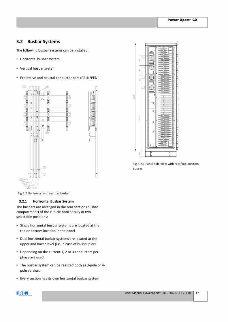
3.2 Busbar Systems
The following busbar systems can be installed:
• Horizontal busbar system
• Vertical busbar system
• Protective and neutral conductor bars (PE+N/PEN)
3.2.1 Horizontal Busbar System
The busbars are arranged in the rear section (busbar
compartment) of the cubicle horizontally in two
selectable positions:
• Single horizontal busbar systems are located at the
top or bottom location in the panel
• Dual horizontal busbar systems are located at the
upper and lower level (i.e. in case of buscoupler)
• Depending on the current 1, 2 or 3 conductors per
phase are used.
• The busbar system can be realized both as 3-pole or 4-
pole version.
• Every section has its own horizontal busbar system
Fig 3.2 Horizontal and vertical busbar
Fig 3.2.1 Panel side view with rear/top position
busbar
Power Xpert® CX
User Manual PowerXpert® CX - 6069511 G01 01 18
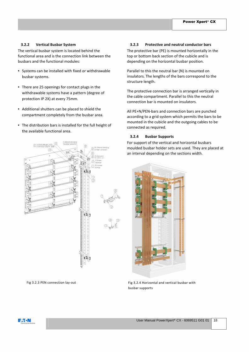
3.2.2 Vertical Busbar System
The vertical busbar system is located behind the
functional area and is the connection link between the
busbars and the functional modules:
• Systems can be installed with fixed or withdrawable
busbar systems.
• There are 25 openings for contact plugs in the
withdrawable systems have a pattern (degree of
protection IP 2X) at every 75mm.
• Additional shutters can be placed to shield the
compartment completely from the busbar area.
• The distribution bars is installed for the full height of
the available functional area.
3.2.3 Protective and neutral conductor bars
The protective bar (PE) is mounted horizontally in the
top or bottom back section of the cubicle and is
depending on the horizontal busbar position.
Parallel to this the neutral bar (N) is mounted on
insulators. The lengths of the bars correspond to the
structure length.
The protective connection bar is arranged vertically in
the cable compartment. Parallel to this the neutral
connection bar is mounted on insulators.
All PE+N/PEN-bars and connection bars are punched
according to a grid system which permits the bars to be
mounted in the cubicle and the outgoing cables to be
connected as required.
3.2.4 Busbar Supports
For support of the vertical and horizontal busbars
moulded busbar holder sets are used. They are placed at
an interval depending on the sections width.
Fig 3.2.3 PEN connection lay-out Fig 3.2.4 Horizontal and vertical busbar with
busbar supports
Power Xpert® CX
User Manual PowerXpert® CX - 6069511 G01 01 19
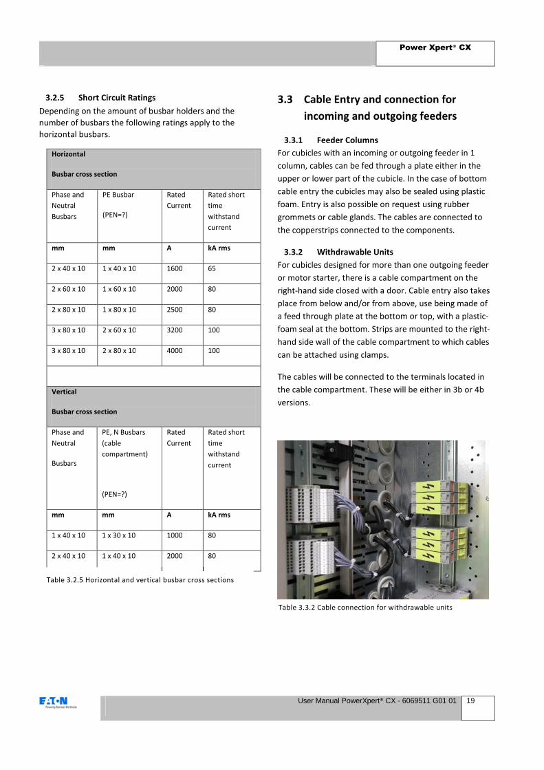
3.2.5 Short Circuit Ratings
Depending on the amount of busbar holders and the
number of busbars the following ratings apply to the
horizontal busbars.
Horizontal
Busbar cross section
Phase and
Neutral
Busbars
PE Busbar
(PEN=?)
Rated
Current
Rated short
time
withstand
current
mm mm A kA rms
2 x 40 x 10 1 x 40 x 10 1600 65
2 x 60 x 10 1 x 60 x 10 2000 80
2 x 80 x 10 1 x 80 x 10 2500 80
3 x 80 x 10 2 x 60 x 10 3200 100
3 x 80 x 10 2 x 80 x 10 4000 100
Vertical
Busbar cross section
Phase and
Neutral
Busbars
PE, N Busbars
(cable
compartment)
(PEN=?)
Rated
Current
Rated short
time
withstand
current
mm mm A kA rms
1 x 40 x 10 1 x 30 x 10 1000 80
2 x 40 x 10 1 x 40 x 10 2000 80
3.3 Cable Entry and connection for
incoming and outgoing feeders
3.3.1 Feeder Columns
For cubicles with an incoming or outgoing feeder in 1
column, cables can be fed through a plate either in the
upper or lower part of the cubicle. In the case of bottom
cable entry the cubicles may also be sealed using plastic
foam. Entry is also possible on request using rubber
grommets or cable glands. The cables are connected to
the copperstrips connected to the components.
3.3.2 Withdrawable Units
For cubicles designed for more than one outgoing feeder
or motor starter, there is a cable compartment on the
right-hand side closed with a door. Cable entry also takes
place from below and/or from above, use being made of
a feed through plate at the bottom or top, with a plastic-
foam seal at the bottom. Strips are mounted to the right-
hand side wall of the cable compartment to which cables
can be attached using clamps.
The cables will be connected to the terminals located in
the cable compartment. These will be either in 3b or 4b
versions.
Table 3.2.5 Horizontal and vertical busbar cross sections
Table 3.3.2 Cable connection for withdrawable units

Power Xpert® CX
User Manual PowerXpert® CX - 6069511 G01 01 20
3.3.3 Fixed Units
Main current cables of outgoing feeder units in the fixed
versions are connected directly to the equipment using
cable lugs or terminals.
3.4 Safety features
The switchgear may be provided with the following
safety features:
• A sheet steel enclosure to protect against contact
with live components.
• Compartments with earthed steel walls in either
Form 3b or 4b degree of separation.
• Optional shutters shielding live parts when a
switch is withdrawn.
• Mechanical interlocks to prevent unintentional
switching.
• Provision for locating locks on the operating
handles of the compartments and breakers.
• Visible indication of the test and disconnect
positions of compartment and breakers.
• Special equipment intended for the earthing of
cables and busbars.
• A continuous earthing busbar extending the full
length of the installation.
• Locks on panel doors (3 point lock system on full
panel height doors)
3.4.1 Execution of work
WARNING
• ALWAYS check that the equipment is voltage
free.
• Fit suitable earthing.
• NEVER approach an unearthed installation.
Ensure maintenance work is carried out timely, in
accordance with the instructions in this manual
Replace worn and/or damaged parts only with original
Eaton spares or spares approved by Eaton
Take the following minimum precautions when
carrying out work:
Working on live or partly live installation:
• Clearly indicate the working area.
• Make sure that the installation is clean and dry;
check for leakage paths where voltage could track
to the outside.
• Fit earthing to the panel, which is being worked
on; only operate on earthed panels.
• Always check that the part that is being worked on
is voltage free.
Working on a voltage free installation:
• Fit earthing; work on earthed panels only.
• Always check that the system is voltage free.
When re-commissioning:
• Check that all the work in the immediate area has
been completed.
• Check (if necessary) that all related work in other
areas has been completed.
• Check the safety of all personnel concerned.
• Remove safety earthing and other safety
provisions.

Power Xpert® CX
User Manual PowerXpert® CX - 6069511 G01 01 21
3.5 General technical data
This paragraph contains only general technical data. For details concerning your own installation, see the information
pack supplied with your installation, which includes this manual.
3.5.1 Electrical data
System Power Xpert CX
Rated operational 400/415/440 V
Rated frequency 50/60 Hz
Main busbar data
Rated insulation voltage 1000 V
Rated impulse withstand voltage 12 kV
Rated current Up to 4000 A
Rated short-time withstand current Up to 100 kA 1 s
Rated peak withstand current Up to 220 kA
Vertical distribution busbar data
Rated insulation voltage 1000 V
Rated impulse withstand voltage 12 kV
Rated current 2x500 (1000) / 2x1000 (2000) A 1)
Rated short-time withstand current 65 and 80 kA, 1 s
Rated peak withstand current Up to 176 kA
Enclosure data
Degree of protection IP31 and IP55 with closed doors, IPXXB with open doors
Form of separation Form 3b and Form 4b
Entry of cables Top and/or bottom
Access Front
Standard Color RAL 7035
Note: 1)The distribution busbar is central fed. The current is equally divided over the lower and upper half of the distribution basbar.
Table 3.5.1 PowerXpert CX technical Data sheet

Power Xpert® CX
User Manual PowerXpert® CX - 6069511 G01 01 22
3.5.2 Environmental conditions
During operation In accordance with IEC 61439-1 par. 7.1.1,
Limit values below, among others, apply:
Ambient air temperature – lower limit -5°C
Ambient air temperature – upper limit +40°C
Ambient air temperature – daily avg maximum +35°C
Humidity 50 % at 40°C (non-condensing), 90% at 20°C (non condensing)
Pollution degree Industrial: 3
Altitude 2000 m above sea level
Sound level < 70 dBA
EMC environment (imm./em) Environment A and B
During Storage In accordance with IEC 61439-1 par. 7.1.1.
Power Xpert® CX
User Manual PowerXpert® CX - 6069511 G01 01 23
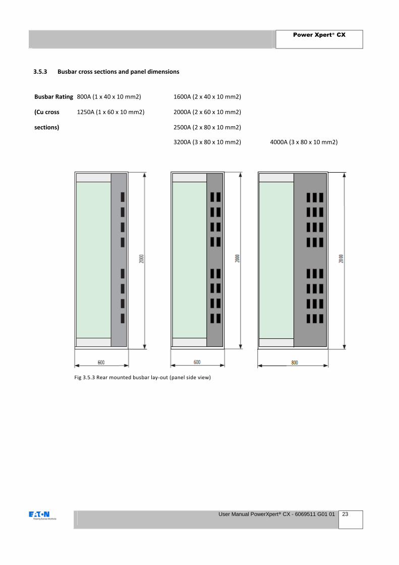
3.5.3 Busbar cross sections and panel dimensions
Busbar Rating 800A (1 x 40 x 10 mm2) 1600A (2 x 40 x 10 mm2)
(Cu cross 1250A (1 x 60 x 10 mm2) 2000A (2 x 60 x 10 mm2)
sections) 2500A (2 x 80 x 10 mm2)
3200A (3 x 80 x 10 mm2) 4000A (3 x 80 x 10 mm2)
Fig 3.5.3 Rear mounted busbar lay-out (panel side view)
Power Xpert® CX
User Manual PowerXpert® CX - 6069511 G01 01 24
3.6 Connection possibilities and ranges
3.6.1 Cubicles with an incoming or one outgoing feeder
There are various possibilities for the connection of these groups:
• Connection using cable-lugs, maximum of two per phase, with the exception of 630 A equipment for which a connection-set has been developed for three cables per phase (copper).
• Using cable-clamping blocks on switches exceeding 1000 A, for one or more cables.
• A connection-set is also available on request for switches exceeding 1000 A, for five cables per phase maximum of 240 mm2.
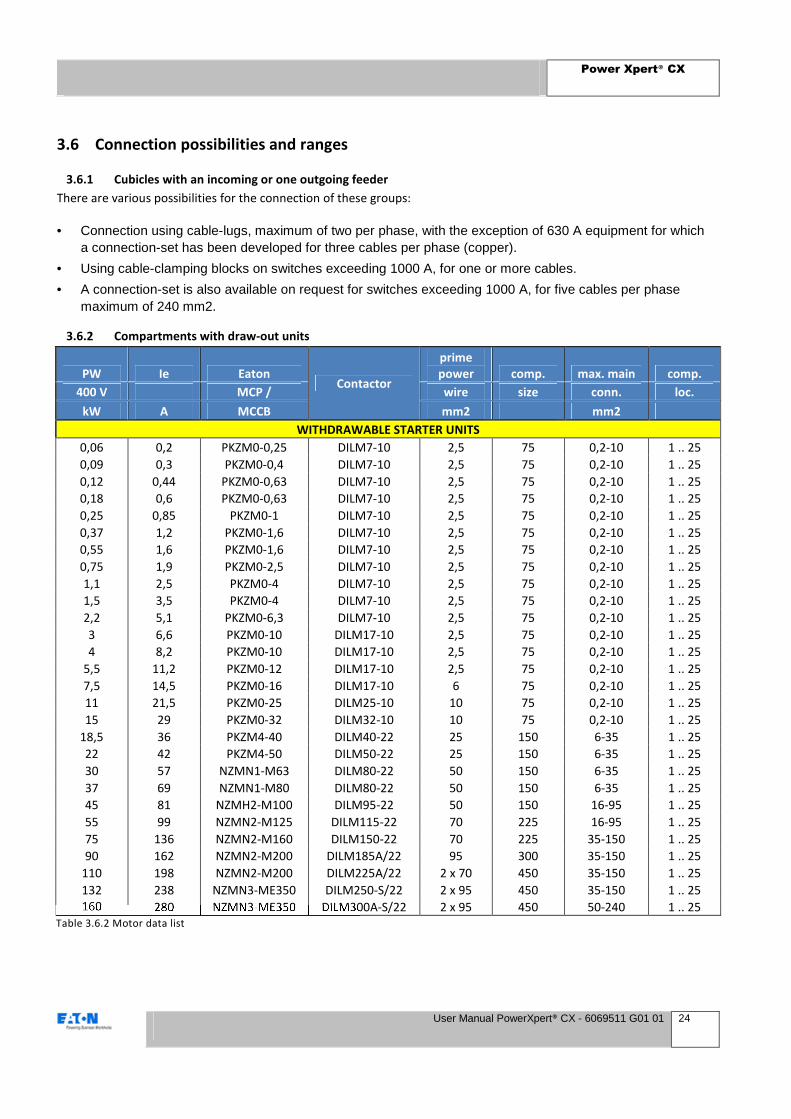
3.6.2 Compartments with draw-out units
PW Ie Eaton Contactor
prime
power comp. max. main comp.
400 V MCP / wire size conn. loc.
kW A MCCB mm2 mm2
WITHDRAWABLE STARTER UNITS
0,06 0,2 PKZM0-0,25 DILM7-10 2,5 75 0,2-10 1 .. 25
0,09 0,3 PKZM0-0,4 DILM7-10 2,5 75 0,2-10 1 .. 25
0,12 0,44 PKZM0-0,63 DILM7-10 2,5 75 0,2-10 1 .. 25
0,18 0,6 PKZM0-0,63 DILM7-10 2,5 75 0,2-10 1 .. 25
0,25 0,85 PKZM0-1 DILM7-10 2,5 75 0,2-10 1 .. 25
0,37 1,2 PKZM0-1,6 DILM7-10 2,5 75 0,2-10 1 .. 25
0,55 1,6 PKZM0-1,6 DILM7-10 2,5 75 0,2-10 1 .. 25
0,75 1,9 PKZM0-2,5 DILM7-10 2,5 75 0,2-10 1 .. 25
1,1 2,5 PKZM0-4 DILM7-10 2,5 75 0,2-10 1 .. 25
1,5 3,5 PKZM0-4 DILM7-10 2,5 75 0,2-10 1 .. 25
2,2 5,1 PKZM0-6,3 DILM7-10 2,5 75 0,2-10 1 .. 25
3 6,6 PKZM0-10 DILM17-10 2,5 75 0,2-10 1 .. 25
4 8,2 PKZM0-10 DILM17-10 2,5 75 0,2-10 1 .. 25
5,5 11,2 PKZM0-12 DILM17-10 2,5 75 0,2-10 1 .. 25
7,5 14,5 PKZM0-16 DILM17-10 6 75 0,2-10 1 .. 25
11 21,5 PKZM0-25 DILM25-10 10 75 0,2-10 1 .. 25
15 29 PKZM0-32 DILM32-10 10 75 0,2-10 1 .. 25
18,5 36 PKZM4-40 DILM40-22 25 150 6-35 1 .. 25
22 42 PKZM4-50 DILM50-22 25 150 6-35 1 .. 25
30 57 NZMN1-M63 DILM80-22 50 150 6-35 1 .. 25
37 69 NZMN1-M80 DILM80-22 50 150 6-35 1 .. 25
45 81 NZMH2-M100 DILM95-22 50 150 16-95 1 .. 25
55 99 NZMN2-M125 DILM115-22 70 225 16-95 1 .. 25
75 136 NZMN2-M160 DILM150-22 70 225 35-150 1 .. 25
90 162 NZMN2-M200 DILM185A/22 95 300 35-150 1 .. 25
110 198 NZMN2-M200 DILM225A/22 2 x 70 450 35-150 1 .. 25
132 238 NZMN3-ME350 DILM250-S/22 2 x 95 450 35-150 1 .. 25
160 280 NZMN3-ME350 DILM300A-S/22 2 x 95 450 50-240 1 .. 25
Table 3.6.2 Motor data list

Power Xpert® CX
User Manual PowerXpert® CX - 6069511 G01 01 25
Remarks
• In order to achieve good connection when using 2.5 mm2 solid wire, the bare conductor must be bent double
for each connection to the main connection block.
• When connecting twined cables up to 16 mm2 to the main connection-block, it is advisable to use cable- end
sleeves.
• All 160 A draw-out units, 2 x 125 mm high and larger, may, on request, be supplied with terminals for optimum
connection of 2 x 95 mm2 (copper).
• When two or three draw-out units are placed next to each other in one compartment, connection is made to
• terminals located in the cable-compartment 1). The connection range of the respective terminals is:
- main current, maximum 10 mm2
- auxiliary current, maximum 2.5 mm2
• A maximum of twenty 2.5 mm2 leads may be connected to the auxiliary connection-block.

Power Xpert® CX
User Manual PowerXpert® CX - 6069511 G01 01 26
4 System assembly
If required the switchgear can be transported and
installed by specialist personnel from Eaton. This chapter
contains information on transporting and setting up
Power Xpert CX switchgear.
4.1 Environmental requirements
The switch room in which the switchgear is set up must
comply with the following:
• All safety regulations applicable locally;
• The requirements set out in the chapter on safety
• The requirements in this paragraph.
4.1.1 Climate
In accordance with IEC 61439-1 par. 7.1.1 the climate in
the switch room must comply with the following:
Humidity: 90% Maximum relative over a period of 1
month. In new buildings it is essential to dry out the
area before installing the system.
• Temperature:
- Maximum +40°C, measured over a period of
24 hours.
- Average not more than +35°C.
- Minimum not less than -5°C.
• The room must be free from dust, corrosive or
flammable gases and salts.
If the installation has to operate in a less suitable
operating environment it may be necessary to take
special precautions. Users should consult Eaton.
4.1.2 Room for extension
If necessary reserve sufficient space for later extension
of the installation (can be on both sides extended).
4.1.3 Floor
The floor of the operating area should comply with the
following:
• The floor must be flat and level to within ± 2 mm;
• The floor must not have any raised areas (bumps)
though indentations are permitted;
• The floor must be of adequate strength.
Sections or foundation frames set in the floor can be
used as the support surface for the installation. The area
between the floor sections and the panel must always be
filled in with filler plates to create a suitable support
surface.
Details on the dimensions and weight of the switchgear
can be found in the floor plan drawing in the information
pack (see example next page).
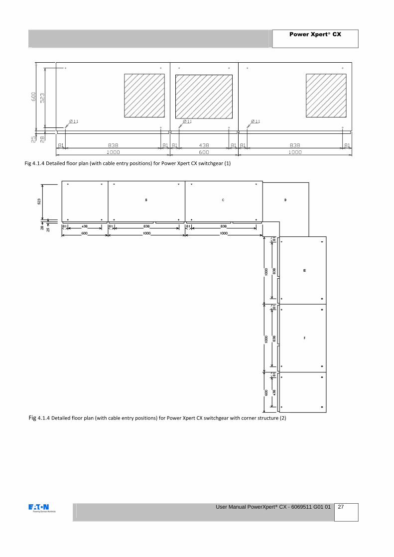
4.1.4 Floor plan
The illustration on the next page gives an example of
how equipment is set up.
Use this example or the floor plan in the information
pack to check that the floor recesses are the right size
and executed correctly.
4.1.5 During transport and storage
If the switchgear panels are stored temporarily prior to
installation, or during transport:
• Do not unpack the switchgear panels;
• Store the switchgear panels vertically in a dry and
dust-free area;
• Ensure that the transport and storage
environment complies as far as possible with the
requirements of IEC 61439-1, par. 7.1.1;
• Avoid condensation caused by rapid temperature
changes.
NOTE
If the installation is kept in poor conditions in the open
air, corrosion and a reduction in the level of quality may
result.
Power Xpert® CX
User Manual PowerXpert® CX - 6069511 G01 01 27
Fig 4.1.4 Detailed floor plan (with cable entry positions) for Power Xpert CX switchgear (1)
Fig 4.1.4 Detailed floor plan (with cable entry positions) for Power Xpert CX switchgear with corner structure (2)
Power Xpert® CX
User Manual PowerXpert® CX - 6069511 G01 01 28
4.2 System transport
Shipment
On-site delivery is contingent on the presence of an
appropriate access route.
A Power Xpert CX installation is normally transported in
individual sections. The sections can be assembled on
site. When they are shipped with more than 1 section
then the maximum length is 2400mm. The sections are
placed onto pallets and are packed in styro foam and
plastic foil to prevent against damage. The pallets are
attached to the equipment by means of steel straps.
4.2.1 Delivery inspection
The cubicles should be unpacked and inspected for
transport damage and/or missing parts. Should any parts
be missing or cubicles have incurred damage during
transport, please advise the transport service and Eaton
within seven calendar days of receipt, in order for the
claim to be settled.
When inspecting Cubicles, locate and identify any fixing
kits etc., also remove any transport packing from within
compartments, before assembly and putting the
switchboard into service.
4.2.2 Instructions for transport
The user is to follow the supplier’s instructions.
Transport
• During transport, suitable precautions are taken:
• To prevent intrusion of dust.
• To prevent intrusion of moisture (e.g. rain).
• To prevent against damage.
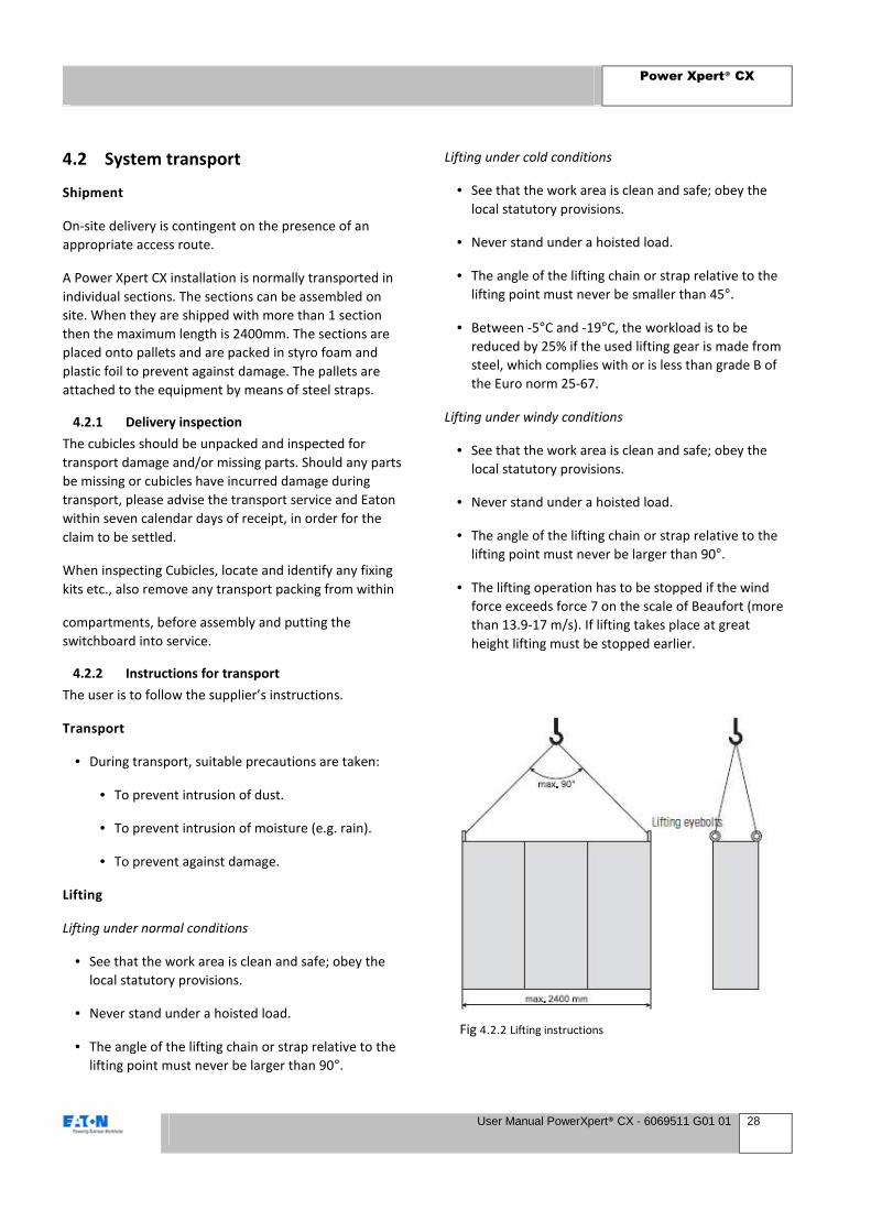
Lifting
Lifting under normal conditions
• See that the work area is clean and safe; obey the
local statutory provisions.
• Never stand under a hoisted load.
• The angle of the lifting chain or strap relative to the
lifting point must never be larger than 90°.
Lifting under cold conditions
• See that the work area is clean and safe; obey the
local statutory provisions.
• Never stand under a hoisted load.
• The angle of the lifting chain or strap relative to the
lifting point must never be smaller than 45°.
• Between -5°C and -19°C, the workload is to be
reduced by 25% if the used lifting gear is made from
steel, which complies with or is less than grade B of
the Euro norm 25-67.
Lifting under windy conditions
• See that the work area is clean and safe; obey the
local statutory provisions.
• Never stand under a hoisted load.
• The angle of the lifting chain or strap relative to the
lifting point must never be larger than 90°.
• The lifting operation has to be stopped if the wind
force exceeds force 7 on the scale of Beaufort (more
than 13.9-17 m/s). If lifting takes place at great
height lifting must be stopped earlier.
Fig 4.2.2 Lifting instructions

Power Xpert® CX
User Manual PowerXpert® CX - 6069511 G01 01 29
4.2.3 Transport in the operating area
The installation can be moved in the operating area by
means of all suitable aids. This can vary from solid bars,
lifting trolleys, inside cranes or forklift trucks.
1 Lift the Power Xpert CX on one side and put a solid
bar under the installation.
2 Repeat this until a bar is present under each
section.
3 Put some bars in front of the transport direction
and push the Power Xpert CX towards its final
location.
4 Remove the bars in reverse order.
CAUTION
Make sure, under each section is a solid bar
present continuously. This is to prevent sagging.
Lifting trolleys
1 Lift the Power Xpert CX on one side and put a
lifting trolley under the installation end.
2 Support the installation adequately to prevent
rolling away
3 Lift the Power Xpert CX on the other side and put
a lifting trolley under the installation end
4 Carefully push the Power Xpert CX towards its final
location.
5 Remove the lifting trolleys in reverse order.
Inside cranes
Transport by indoor cranes is done in the same way as
outside transport. Please refer to the applicable
paragraph above.
Forklift trucks
Transport by forklift trucks is done in the same way as
outside transport. Please refer to the applicable
paragraph above.
4.2.4 Installation of a Switchboard
Switchboards are supplied with a standard 45 mm plinth
(part of the frame). Position the switchboard on the base
frame (if supplied) or directly on the floor in the required
location.
• Open the doors of the cable compartments, to gain
access to the mounting holes in the bottom of the
cubicle.
• Where possible gain access to the equipment
sections front located mounting holes in the bottom
of the cubicle, by opening the overall door or
removing the bottom bolt on cover.
• Insert and tighten the fastening bolts, refit plates
and close doors.

Power Xpert® CX
User Manual PowerXpert® CX - 6069511 G01 01 30
4.2.5 Unpacking the delivery
Dispose of the packing material in an environmentally
sound manner. It is essential to adequately pack the
products so as to avoid damage. All packing materials
are inoffensive to the environment and they can be re-
used. If any wood is used, it has not been treated
chemically. Foils are from polyethylene (PE). CFC-free
polystyrene foam is used for padding. These plastics are
pure hydrocarbon compounds, so they can be recycled.
If incinerated, there will be no emissions that are
offensive to the environment.
REMARK
By using and reusing packing materials, we can
save on raw materials. This again reduces the
amount of waste.
Procedure
1 As required, remove the packaging materials from
the equipment.
2 Dispose the packaging materials in an
environmental friendly manner.
4.2.6 Inspection of the floor
NOTE
The maximum difference in height with reference
to width and length of the installation shall not
exceed 4 mm.
1 Prior to the installation, make sure the floor is
smooth and level.
2 Find the highest point in the installation area.
Installation of the sections should start from this
point. Differences in height must be eliminated
with the use of leveling plates.
3 Check the location of the recesses with reference
to the approved floor plan, which is part of the
information package to which this manual
belongs.
4 Check the location of the cable trench / cable
cellar with reference to the floor plan.
5 If any cables come out of the floor, make sure they
are electrically insulated.
6 Put the cables downwards or into the cable
cellar/trench in such a way that the Power Xpert
CX switchgear can be installed on top.
4.3 Coupling of the panels
Coupling of the panels can be achieved in 2 ways, before
finalizing the coupling of the busbars. In 8 positions on
predefined locations (preferred), or as close as possible
to these locations in the square hole pattern along the
whole height of the panel.
method 1 method 2
Table 4.3 Coupling Accessories
Fig4.3 Coupling of a panel

Power Xpert® CX
User Manual PowerXpert® CX - 6069511 G01 01 31
4.4 Coupling of the busbars
The first step when coupling the busbars is to loosely
attach the connection strips to one of the panels that
have to be connected.
The next step is to move the panels towards each other
in a straight line until the frame is connected. The
busbars should be overlapping in this stage and the
panels can be fixed to each other (see chapter: coupling
of panels)
The amount and size of connection pieces to be used
depends on the main busbar rating and size as seen
below.
The length of the hexagonal socket-head coupling bolts
M12 used to clamp the busbars together depends upon
the dimensions of the busbars, as shown in the table.
Main busbar isolation covers have to be installed on
both ends of the busbar (see picture below).
Fig 4.4 Busbar coupling (1)
Fig 4.4 Busbar coupling (2)
Fig 4.4 Busbar coupling (3)
Fig 4.4 Busbar coupling (4)

Power Xpert® CX
User Manual PowerXpert® CX - 6069511 G01 01 32
4.5 Connection of wiring and cables
Different types of cables can be connected to the
switchgear for example 1 or 3 core paper lead, XLPE or
synthetic cables.
4.5.1 Connecting a main power cable to the
withdrawable unit
Proceed as follows:
1. Open the cable way door
2. Remove the protective covers of the terminals
3. “Open” the terminal to accept the cable
4. Gland the cable at the cable support
5. Strip the cable
6. Connect the stripped cable to the terminal
7. “Close” the terminal when cables are connected
/
4.5.2 Connecting the auxiliary cables to the
withdrawable unit
Proceed as follows:
1. Place the auxiliary wiring in the cable duct that
is placed in the cableway
2. Open the terminal with a special tool or
flathead screwdriver
3. Connect the auxiliary cable to the right
numbered terminal
4. Remove the screwdriver to fix the auxiliary
cable
4.5.3 Connection of main power cable to the air
circuit breaker
Proceed as follows:
1. Feed the main power cable trough the glanding
plate and gland the cable
2. Connect the cable to either the cable gland or
cable shoe that is connected to the equipment
like below:
Fig 4.5.1 Connecting power cables onto a withdrawable unit
Fig 4.5.2 Connecting auxiliary cables onto a withdrawable unit
Fig 4.5.3 Connection terminals of an Air Circuit Breaker

Power Xpert® CX
User Manual PowerXpert® CX - 6069511 G01 01 33
5 System operation
5.1 Testing
Before putting the switchboard into service Routine tests
shall be carried out in accordance with IEC 61439 and
local regulations. As a minimum tests will include:
• Full inspection of the assembly, wiring and
electrical operation tests (if necessary).
• A dielectric test.
• Checking of protective measures and electrical
continuity of the protective circuit.
This chapter contains the basic operating procedures for
components used in Eaton Power Xpert CX switchgear.
Refer to the individual component technical
documentation for detailed information.
WARNING
Interlocks must only be removed by a specialist, and only
if absolutely necessary for operational reasons. When
removing an interlock, the specialist must take special and
adequate safety measures to prevent situations, which
might have fatal consequences.
CAUTION
The switchgear must be operated only as prescribed in
this manual. Actions, which are not prescribed, or actions
prescribed in unusual circumstances, must be taken only
with the approval of the responsible Eaton specialist. The
latter’s instructions must be followed exactly.
NOTE
Only qualified experts and qualified operating specialists
may operate the equipment. No other personnel must be
present in the operating area.
5.2 Setting up of Equipment
In addition to testing it will be necessary to set
protective devices to the required levels, before putting
the switchboard into service. This will include but not be
limited to the following:
· Setting MCCB (NZM) characteristics.
· Setting of ACB (NRX/ Magnum) characteristics.
· Setting timers etc., within control schemes.
Adjustable
Trip Unit
Fig 5.2 Setting of NZM for protection of cables
Fig 5.2 Setting of NZM for protection of motors
Fig 5.2 NRX and Magnum Air Circuit Breakers
Power Xpert® CX
User Manual PowerXpert® CX - 6069511 G01 01 34
5.3 Opening and closing doors and
covers
All compartment doors containing electrical equipment
and cabling are provided with key-operated quick lock
devices. Ensure the Rotary handle, where fitted, is
turned to the off position before re-closing the door. The
cableway doors are provided with quick-lock devices
which are knob or key-operated.
The doors may be unlocked by turning these through
90°. Circuit-breakers in the assembly are provided with a
door-catch and if necessary door interlocks. In order to
be able to open a door, any interlocks which have been
fitted ought to be disengaged. This can be accomplished
by turning the knob or handle to the off-position. The
door can now be opened.
The covers of the withdrawable compartments are to be
opened like described in chapter 2.1.5
5.4 Operation
This chapter describes operating actions relating to
standard equipment. The operation of optional
equipment and accessories is included in the operating
instructions. These can be found in the information pack,
which includes this manual.
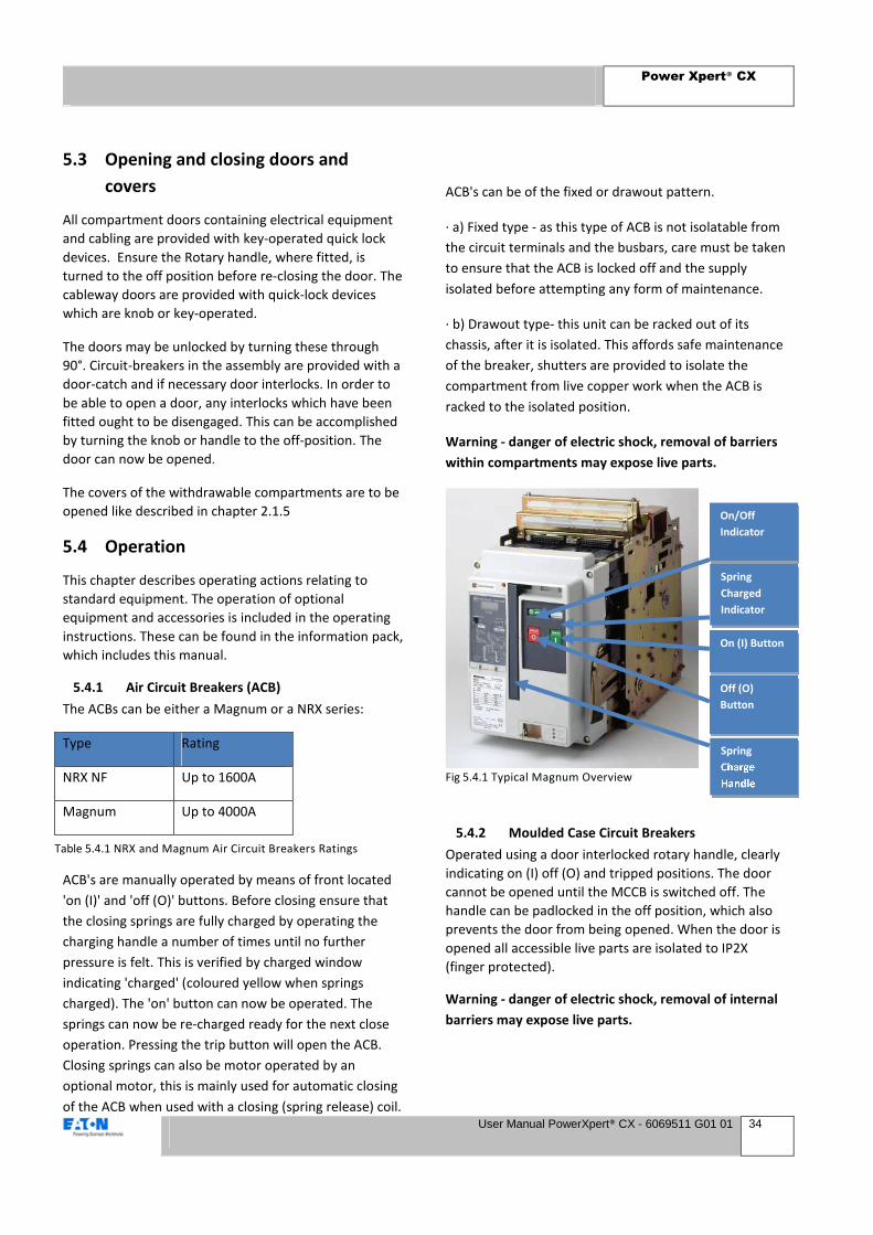
5.4.1 Air Circuit Breakers (ACB)
The ACBs can be either a Magnum or a NRX series:
Type Rating
NRX NF Up to 1600A
Magnum Up to 4000A
ACB's are manually operated by means of front located
'on (I)' and 'off (O)' buttons. Before closing ensure that
the closing springs are fully charged by operating the
charging handle a number of times until no further
pressure is felt. This is verified by charged window
indicating 'charged' (coloured yellow when springs
charged). The 'on' button can now be operated. The
springs can now be re-charged ready for the next close
operation. Pressing the trip button will open the ACB.
Closing springs can also be motor operated by an
optional motor, this is mainly used for automatic closing
of the ACB when used with a closing (spring release) coil.
ACB's can be of the fixed or drawout pattern.
· a) Fixed type - as this type of ACB is not isolatable from
the circuit terminals and the busbars, care must be taken
to ensure that the ACB is locked off and the supply
isolated before attempting any form of maintenance.
· b) Drawout type- this unit can be racked out of its
chassis, after it is isolated. This affords safe maintenance
of the breaker, shutters are provided to isolate the
compartment from live copper work when the ACB is
racked to the isolated position.
Warning - danger of electric shock, removal of barriers
within compartments may expose live parts.
5.4.2 Moulded Case Circuit Breakers
Operated using a door interlocked rotary handle, clearly
indicating on (I) off (O) and tripped positions. The door
cannot be opened until the MCCB is switched off. The
handle can be padlocked in the off position, which also
prevents the door from being opened. When the door is
opened all accessible live parts are isolated to IP2X
(finger protected).
Warning - danger of electric shock, removal of internal
barriers may expose live parts.
On/Off
Indicator
Spring
Charged
Indicator
On (I) Button
Off (O)
Button
Spring
Charge
Handle
Table 5.4.1 NRX and Magnum Air Circuit Breakers Ratings
Fig 5.4.1 Typical Magnum Overview

Power Xpert® CX
User Manual PowerXpert® CX - 6069511 G01 01 35
5.4.3 Incoming devices
These can be MCCB's or ACB's. The manual operation of
these devices is the same as described the previous
chapters but additional care should be taken as the line
(cable) side of these devices, when used as incoming
circuits will be live.
Warning - danger of electric shock, ensure that the
supply is isolated upstream of the switchboard before
accessing incoming terminals.
5.4.4 Specific Literature and Manuals
More detailed information is available for all equipment
fitted to the switchboard, if not provided with the
switchboard, this can be provided on request.
5.5 Mechanical operation withdrawable
units
When the door is open the switch can be operated
directly from the controls mounted on the front of the
switch. For full information refer to the switch user
manual.
NOTE
The door cannot be opened when the switch is in
the OPERATION position. To open the door make
sure the switch is in the OFF (O) position and
press the mechanical test position button
advance to the other positions.
In the next chapters the drawer positions and operation
are indicated. Moving from any one position to another
position always requires that the MCP or MCCB is
switched off (O) and the unlocking button is fully pushed
before moving the withdrawable unit.
Mechanical
test position
button
Fig 5.5 Withdrawing unit with mechanical test position button

Power Xpert® CX
User Manual PowerXpert® CX - 6069511 G01 01 36
5.5.1 Withdrawable unit positions
CONNECTED POSITION:
- Connected – ON (I)
The unit is inserted, main disconnect is closed, main and
control circuit is connected.
- Connected – OFF (O)
The unit is inserted, main disconnect is open, main and
control circuits are connected, padlocking is possible.
TEST POSITION:
The unit is partially withdrawn and is separated 30 mm
from the distribution bars, main disconnect is open,
main circuit is disconnected, control circuit is connected,
the test button is illuminated, padlocking is possible.
DISCONNECTED POSITION:
The unit is partially withdrawn and is separated 45 mm
from the distribution bars, main disconnect is open,
main and control circuits are disconnected, padlocking
is possible.
Fig 5.5.1 Withdrawing unit in test position (top view)
Fig 5.5.1 Withdrawing unit in connected position (top view) Fig 5.5.1 Withdrawing unit in disconnected position (top view)
Power Xpert® CX
User Manual PowerXpert® CX - 6069511 G01 01 37
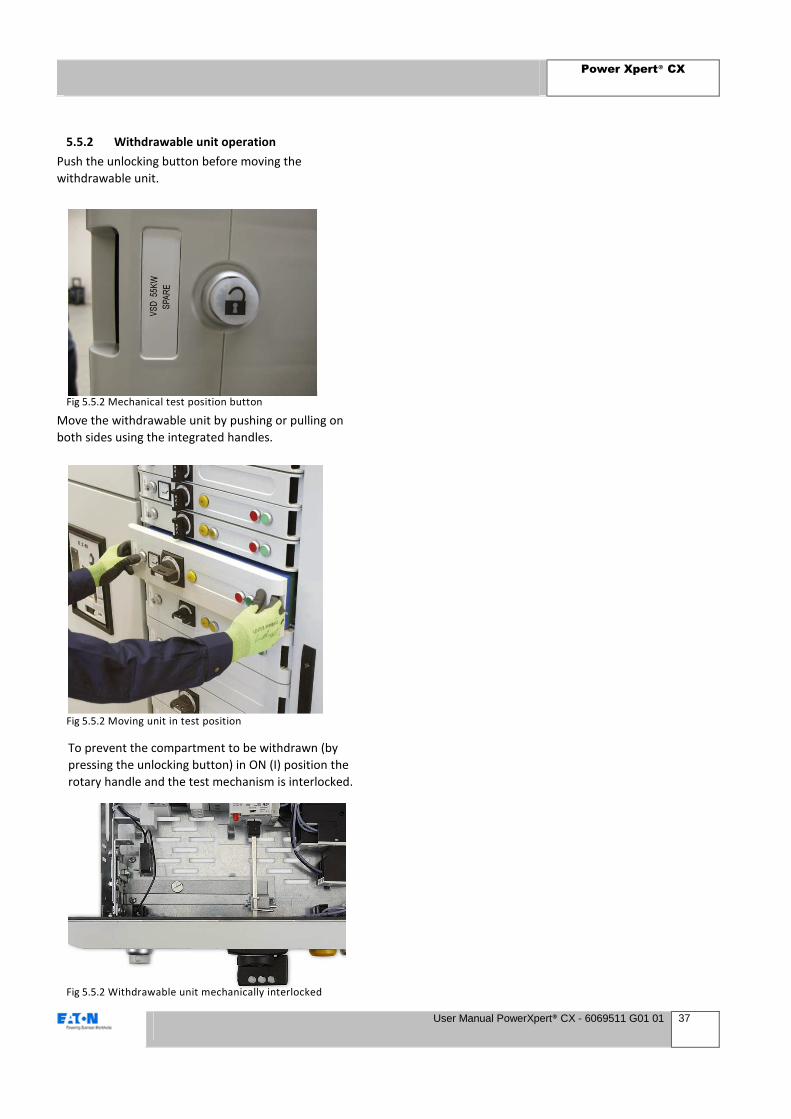
5.5.2 Withdrawable unit operation
Push the unlocking button before moving the
withdrawable unit.
Move the withdrawable unit by pushing or pulling on
both sides using the integrated handles.
To prevent the compartment to be withdrawn (by
pressing the unlocking button) in ON (I) position the
rotary handle and the test mechanism is interlocked.
Fig 5.5.2 Mechanical test position button
Fig 5.5.2 Moving unit in test position
Fig 5.5.2 Withdrawable unit mechanically interlocked

Power Xpert® CX
User Manual PowerXpert® CX - 6069511 G01 01 38
5.6 Decommissioning
5.6.1 Dismantling
WARNING
Prior to dismantling, ensure that the entire
installation is voltage free
WARNING
The components are not designed for field
dismantling and should be returned to Eaton.
The following safety measures must be taken when
dismantling the switchgear
• During dismantling use protective equipment such
as safety goggles, gloves, protective footwear and
dust hoods.
• Watch out for sharp edges on metal panels and
other parts.
• Use suitable and safe tools.
5.6.2 Disposal
Power Xpert CX switchgear should be disposed of in an
environmentally responsible manner. Substances and
materials arising from dismantling should be
destroyed, re-used or disposed of in accordance with
the regulations currently in force.
The following table gives a list of materials that may be
found in Power Xpert CX switchgear. All materials used
in the manufacture of the Power Xpert CX can be
recycled. No toxic or harmful products are generated
in the normal use of the switchgear.

Power Xpert® CX
User Manual PowerXpert® CX - 6069511 G01 01 39
6 System inspection,
maintenance and repair
The maintenance described in this chapter may be
carried out by the user’s qualified personnel, with due
attention to and compliance with instructions and safety
regulations.
6.1 Logbook
The user should keep a logbook with data relating to the
installation and any maintenance and repair carried out.
The logbook should at least include the following:
• All important incidents occurring in and with the
switchgear
• All faults;
• All maintenance work carried out;
• All repairs carried out.
6.2 Inspection and maintenance, general
Power Xpert CX switchgear and the components used in
them require little maintenance. However, inspections
and checks should be made at regular intervals and
preventive maintenance carried out.
The first inspection is best carried out after six months of
operation. A suitable inspection and maintenance
schedule can be set up on the basis of this initial
inspection.
If required, Eaton can, at regular intervals or when
considered necessary, carry out an intensive inspection
of the installation and make recommendations with
regard to life extension of the equipment.
Periodic checks can be made by the user’s own qualified
personnel. Eaton can provide guidelines and, if
necessary, training for these.
REMARK
In the event of a fault always contact Eaton .
6.3 Checking and maintenance schedule
for components
For checks and maintenance on the components,
reference should be made to their individual manuals.
Checking and maintenance schedule for Power Xpert CX
switchgear
• Periodic check Annually
• Maintenance: Every 5 years.
WARNING
Inspections, checks and maintenance operations
should only be carried out by authorised
specialist personnel. Before inspections, checks
and maintenance operations are commenced, all
necessary steps must be taken to ensure safe
working. This means among other things that:
• All parts of the system must be voltage free
and earthed.
• Protective plates must only be removed after
the installation has been made completely
safe.
Power Xpert® CX
User Manual PowerXpert® CX - 6069511 G01 01 40
6.3.1 Periodic check
Carry out visual inspection checking:
• For dirt, dust and moisture;
• Rodents and other small animals;
• Instruments and relays for faults;
• For loose or discoloured wiring;
• Core end terminations/terminal strips;
• For loose plates/mounting material;
• For exceptional wear.
• Oxidation (If there is much oxidation on the metal
parts this must be removed (not by electrical
connections). The cause must also be removed
(this is very often poor air conditioning in the
installation room).
If there is a lot of dust or sand in the assembly this ought
to be properly vacuumed up. The cause of this
accumulation of dust or sand ought to be removed.
Check door-interlocks, hinges, locks and seals (gaskets)
for proper state and functioning. If necessary clean with
a dry cloth.
Check all outgoing main circuit connections by tightening
up the bolts to the prescribed torque rating (see next
page). Random checks should be carried out on
secondary connections in order to check that the wires
are properly attached.
All hand-operated switches should be turned on and off
five times.
Withdrawable Units
Remove the draw-out units one by one and check the
contents to see whether all primary and secondary
connections are secure.
Functional Check
All electrically working components (relays, ammeters,
on and off switching coils, circuit-breakers, etc.) should
be checked for correct functioning. After this check has
taken place, depending upon circumstances and the
results gained, it must be decided whether the checks, or
elements of them, should take place once a year or after
a number of years, up to a maximum of five years.
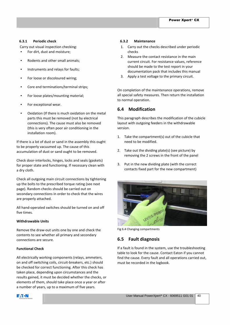
6.3.2 Maintenance
1. Carry out the checks described under periodic
checks
2. Measure the contact resistance in the main
current circuit. For resistance values, reference
should be made to the test report in your
documentation pack that includes this manual
3. Apply a test voltage to the primary circuit.
On completion of the maintenance operations, remove
all special safety measures. Then return the installation
to normal operation.
6.4 Modification
This paragraph describes the modification of the cubicle
layout with outgoing feeders in the withdrawable
version.
1. Take the compartment(s) out of the cubicle that
need to be modified.
2. Take out the dividing plate(s) (see picture) by
removing the 2 screws in the front of the panel
3. Put in the new dividing plate (with the correct
contacts fixed part for the new compartment)
6.5 Fault diagnosis
If a fault is found in the system, use the troubleshooting
table to look for the cause. Contact Eaton if you cannot
find the cause. Every fault and all operations carried out,
must be recorded in the logbook.
Fig 6.4 Changing compartments
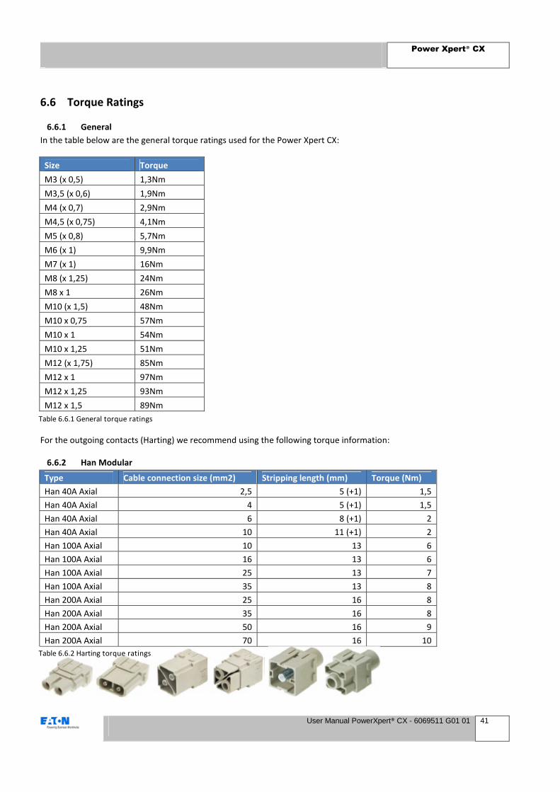
Power Xpert® CX
User Manual PowerXpert® CX - 6069511 G01 01 41
6.6 Torque Ratings
6.6.1 General
In the table below are the general torque ratings used for the Power Xpert CX:
Size Torque
M3 (x 0,5) 1,3Nm
M3,5 (x 0,6) 1,9Nm
M4 (x 0,7) 2,9Nm
M4,5 (x 0,75) 4,1Nm
M5 (x 0,8) 5,7Nm
M6 (x 1) 9,9Nm
M7 (x 1) 16Nm
M8 (x 1,25) 24Nm
M8 x 1 26Nm
M10 (x 1,5) 48Nm
M10 x 0,75 57Nm
M10 x 1 54Nm
M10 x 1,25 51Nm
M12 (x 1,75) 85Nm
M12 x 1 97Nm
M12 x 1,25 93Nm
M12 x 1,5 89Nm
For the outgoing contacts (Harting) we recommend using the following torque information:
6.6.2 Han Modular
Type Cable connection size (mm2) Stripping length (mm) Torque (Nm)
Han 40A Axial 2,5 5 (+1) 1,5
Han 40A Axial 4 5 (+1) 1,5
Han 40A Axial 6 8 (+1) 2
Han 40A Axial 10 11 (+1) 2
Han 100A Axial 10 13 6
Han 100A Axial 16 13 6
Han 100A Axial 25 13 7
Han 100A Axial 35 13 8
Han 200A Axial 25 16 8
Han 200A Axial 35 16 8
Han 200A Axial 50 16 9
Han 200A Axial 70 16 10
Table 6.6.1 General torque ratings
Table 6.6.2 Harting torque ratings
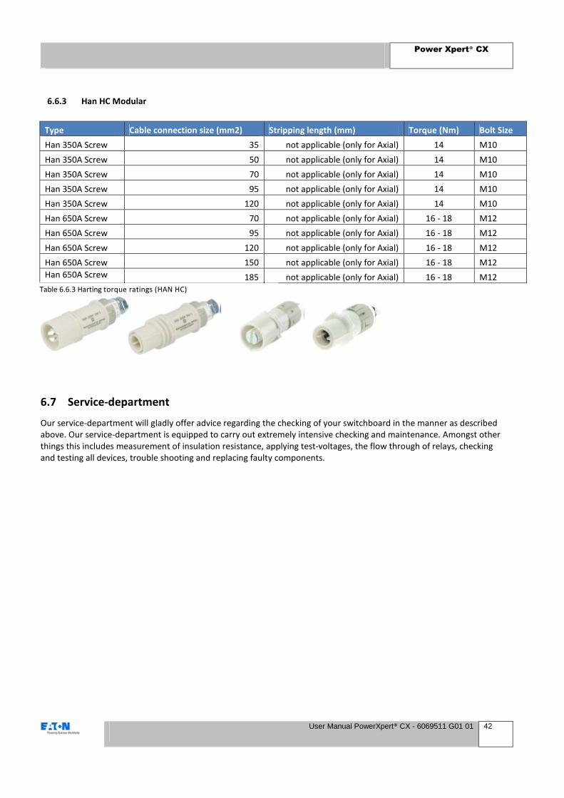
Power Xpert® CX
User Manual PowerXpert® CX - 6069511 G01 01 42
6.6.3 Han HC Modular
Type Cable connection size (mm2) Stripping length (mm) Torque (Nm) Bolt Size
Han 350A Screw 35 not applicable (only for Axial) 14 M10
Han 350A Screw 50 not applicable (only for Axial) 14 M10
Han 350A Screw 70 not applicable (only for Axial) 14 M10
Han 350A Screw 95 not applicable (only for Axial) 14 M10
Han 350A Screw 120 not applicable (only for Axial) 14 M10
Han 650A Screw 70 not applicable (only for Axial) 16 - 18 M12
Han 650A Screw 95 not applicable (only for Axial) 16 - 18 M12
Han 650A Screw 120 not applicable (only for Axial) 16 - 18 M12
Han 650A Screw 150 not applicable (only for Axial) 16 - 18 M12
Han 650A Screw 185 not applicable (only for Axial) 16 - 18 M12
6.7 Service-department
Our service-department will gladly offer advice regarding the checking of your switchboard in the manner as described
above. Our service-department is equipped to carry out extremely intensive checking and maintenance. Amongst other
things this includes measurement of insulation resistance, applying test-voltages, the flow through of relays, checking
and testing all devices, trouble shooting and replacing faulty components.
Table 6.6.3 Harting torque ratings (HAN HC)
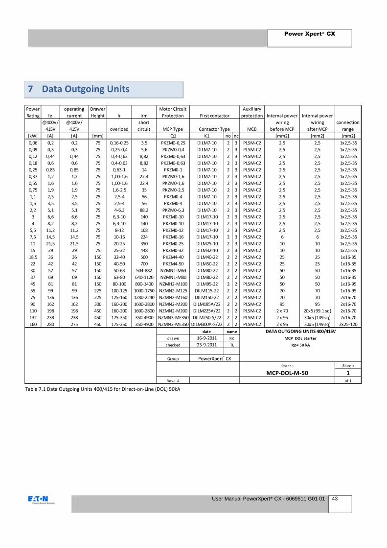
Power Xpert® CX
User Manual PowerXpert® CX - 6069511 G01 01 43
7 Data Outgoing Units
Power
Rating Ie
operating
current
Drawer
Height Ir Irm
Motor Circuit
Protection
Auxiliary
protection
@400V/
415V
@400V/
415V overload
short
circuit MCP Type MCB
[kW] [A] [A] [mm] Q1 K1 no nc [mm2] [mm2] [mm2]
0,06 0,2 0,2 75 0,16-0,25 3,5 PKZM0-0,25 DILM7-10 2 3 PLSM-C2 2,5 2,5 1x2,5-35
0,09 0,3 0,3 75 0,25-0,4 5,6 PKZM0-0,4 DILM7-10 2 3 PLSM-C2 2,5 2,5 1x2,5-35
0,12 0,44 0,44 75 0,4-0,63 8,82 PKZM0-0,63 DILM7-10 2 3 PLSM-C2 2,5 2,5 1x2,5-35
0,18 0,6 0,6 75 0,4-0,63 8,82 PKZM0-0,63 DILM7-10 2 3 PLSM-C2 2,5 2,5 1x2,5-35
0,25 0,85 0,85 75 0,63-1 14 PKZM0-1 DILM7-10 2 3 PLSM-C2 2,5 2,5 1x2,5-35
0,37 1,2 1,2 75 1,00-1,6 22,4 PKZM0-1,6 DILM7-10 2 3 PLSM-C2 2,5 2,5 1x2,5-35
0,55 1,6 1,6 75 1,00-1,6 22,4 PKZM0-1,6 DILM7-10 2 3 PLSM-C2 2,5 2,5 1x2,5-35
0,75 1,9 1,9 75 1,6-2,5 35 PKZM0-2,5 DILM7-10 2 3 PLSM-C2 2,5 2,5 1x2,5-35
1,1 2,5 2,5 75 2,5-4 56 PKZM0-4 DILM7-10 2 3 PLSM-C2 2,5 2,5 1x2,5-35
1,5 3,5 3,5 75 2,5-4 56 PKZM0-4 DILM7-10 2 3 PLSM-C2 2,5 2,5 1x2,5-35
2,2 5,1 5,1 75 4-6,3 88,2 PKZM0-6,3 DILM7-10 2 3 PLSM-C2 2,5 2,5 1x2,5-35
3 6,6 6,6 75 6,3-10 140 PKZM0-10 DILM17-10 2 3 PLSM-C2 2,5 2,5 1x2,5-35
4 8,2 8,2 75 6,3-10 140 PKZM0-10 DILM17-10 2 3 PLSM-C2 2,5 2,5 1x2,5-35
5,5 11,2 11,2 75 8-12 168 PKZM0-12 DILM17-10 2 3 PLSM-C2 2,5 2,5 1x2,5-35
7,5 14,5 14,5 75 10-16 224 PKZM0-16 DILM17-10 2 3 PLSM-C2 6 6 1x2,5-35
11 21,5 21,5 75 20-25 350 PKZM0-25 DILM25-10 2 3 PLSM-C2 10 10 1x2,5-35
15 29 29 75 25-32 448 PKZM0-32 DILM32-10 2 3 PLSM-C2 10 10 1x2,5-35
18,5 36 36 150 32-40 560 PKZM4-40 DILM40-22 2 2 PLSM-C2 25 25 1x16-35
22 42 42 150 40-50 700 PKZM4-50 DILM50-22 2 2 PLSM-C2 25 25 1x16-35
30 57 57 150 50-63 504-882 NZMN1-M63 DILM80-22 2 2 PLSM-C2 50 50 1x16-35
37 69 69 150 63-80 640-1120 NZMN1-M80 DILM80-22 2 2 PLSM-C2 50 50 1x16-35
45 81 81 150 80-100 800-1400 NZMH2-M100 DILM95-22 2 2 PLSM-C2 50 50 1x16-95
55 99 99 225 100-125 1000-1750 NZMN2-M125 DILM115-22 2 2 PLSM-C2 70 70 1x16-95
75 136 136 225 125-160 1280-2240 NZMN2-M160 DILM150-22 2 2 PLSM-C2 70 70 2x16-70
90 162 162 300 160-200 1600-2800 NZMN2-M200 DILM185A/22 2 2 PLSM-C2 95 95 2x16-70
110 198 198 450 160-200 1600-2800 NZMN2-M200 DILM225A/22 2 2 PLSM-C2 2 x 70 20x5 (99.1 sq) 2x16-70
132 238 238 450 175-350 350-4900 NZMN3-ME350 DILM250-S/22 2 2 PLSM-C2 2 x 95 30x5 (149 sq) 2x16-70
160 280 275 450 175-350 350-4900 NZMN3-ME350 DILM300A-S/22 2 2 PLSM-C2 2 x 95 30x5 (149 sq) 2x25-120
date
drawn 16-9-2011
checked 23-9-2011
Group
Sheet:
1Rev.: A of 1
Internal power
wiring
before MCP
Internal power
wiring
after MCP
connection
range
name
RK
TL
DATA OUTGOING UNITS 400/415V
MCP DOL Starter
Icp= 50 kA
Docno.:
MCP-DOL-M-50
PowerXpert® CX
First contactor
Contactor Type
Table 7.1 Data Outgoing Units 400/415 for Direct-on-Line (DOL) 50kA

Power Xpert® CX
User Manual PowerXpert® CX - 6069511 G01 01 44
Power
Rating Ie
operating
current
Drawer
Height Ir Irm
Motor Circuit
Protection
Auxiliary
protection
@400V/
415V
@400V/
415V overload
short
circuit MCP Type MCB
[kW] [A] [A] [mm] Q1 K1 no nc [mm2] [mm2] [mm2]
0,06 0,2 0,2 75 0,16-0,25 3,5 PKZM0-0,25 DILM7-10 2 3 PLSM-C2 2,5 2,5 1x2,5-35
0,09 0,3 0,3 75 0,25-0,4 5,6 PKZM0-0,4 DILM7-10 2 3 PLSM-C2 2,5 2,5 1x2,5-35
0,12 0,44 0,44 75 0,4-0,63 8,82 PKZM0-0,63 DILM7-10 2 3 PLSM-C2 2,5 2,5 1x2,5-35
0,18 0,6 0,6 75 0,4-0,63 8,82 PKZM0-0,63 DILM7-10 2 3 PLSM-C2 2,5 2,5 1x2,5-35
0,25 0,85 0,85 75 0,63-1 14 PKZM0-1 DILM7-10 2 3 PLSM-C2 2,5 2,5 1x2,5-35
0,37 1,2 1,2 75 1,00-1,6 22,4 PKZM0-1,6 DILM7-10 2 3 PLSM-C2 2,5 2,5 1x2,5-35
0,55 1,6 1,6 75 1,00-1,6 22,4 PKZM0-1,6 DILM7-10 2 3 PLSM-C2 2,5 2,5 1x2,5-35
0,75 1,9 1,9 75 1,6-2,5 35 PKZM0-2,5 DILM7-10 2 3 PLSM-C2 2,5 2,5 1x2,5-35
1,1 2,5 2,5 75 2,5-4 56 PKZM0-4 DILM7-10 2 3 PLSM-C2 2,5 2,5 1x2,5-35
1,5 3,5 3,5 75 2,5-4 56 PKZM0-4 DILM7-10 2 3 PLSM-C2 2,5 2,5 1x2,5-35
2,2 5,1 5,1 75 4-6,3 88,2 PKZM0-6,3 DILM7-10 2 3 PLSM-C2 2,5 2,5 1x2,5-35
3 6,6 6,6 75 3,0-12 168 PKE12/XTU-12 DILM17-10 2 3 PLSM-C2 2,5 2,5 1x2,5-35
4 8,2 8,2 75 3,0-12 168 PKE12/XTU-12 DILM17-10 2 3 PLSM-C2 2,5 2,5 1x2,5-35
5,5 11,2 11,2 75 3,0-12 168 PKE12/XTU-12 DILM17-10 2 3 PLSM-C2 2,5 2,5 1x2,5-35
7,5 14,5 14,5 75 8-32 448 PKE32/XTU-32 DILM17-10 2 3 PLSM-C2 2,5 2,5 1x2,5-35
11 21,5 21,5 75 8-32 448 PKE32/XTU-32 DILM25-10 2 3 PLSM-C2 10 10 1x2,5-35
15 29 29 75 8-32 448 PKE32/XTU-32 DILM32-10 2 3 PLSM-C2 10 10 1x2,5-35
18,5 36 36 150 32-40 320-560 NZMH2-M40 DILM80-22 2 2 PLSM-C2 16 16 1x16-35
22 42 42 150 40-50 400-700 NZMH2-M50 DILM80-22 2 2 PLSM-C2 25 25 1x16-35
30 57 57 150 50-63 504-882 NZMH2-M63 DILM80-22 2 2 PLSM-C2 25 25 1x16-35
37 69 69 150 63-80 640-1120 NZMH2-M80 DILM80-22 2 2 PLSM-C2 50 50 1x16-35
45 81 81 150 80-100 800-1400 NZMH2-M100 DILM95-22 2 2 PLSM-C2 50 50 1x16-95
55 99 99 225 100-125 1000-1750 NZMH2-M125 DILM115-22 2 2 PLSM-C2 70 70 1x16-95
75 136 136 225 125-160 1280-2240 NZMH2-M160 DILM150-22 2 2 PLSM-C2 70 70 2x16-70
90 162 162 300 160-200 1600-2800 NZMH2-M200 DILM185A/22 2 2 PLSM-C2 95 95 2x16-70
110 198 198 450 160-200 1600-2800 NZMH2-M200 DILM225A/22 2 2 PLSM-C2 2 x 70 20x5 (99.1 sq) 2x16-70
132 238 238 450 175-350 350-4900 NZMH3-ME350 DILM250-S/22 2 2 PLSM-C2 2 x 95 30x5 (149 sq) 2x16-70
160 280 275 450 175-350 350-4900 NZMH3-ME350 DILM300A-S/22 2 2 PLSM-C2 2 x 95 30x5 (149 sq) 2x25-120
date
drawn 16-9-2011
checked 23-9-2011
Group
Sheet:
1Rev.: A of 1
Docno.:
MCP-DOL-M-80
PowerXpert® CX
RK MCP DOL Starter
TL Icp= 80 kA
First contactor Internal power
wiring
before MCP
Internal power
wiring
after MCP
connection
rangeContactor Type
name DATA OUTGOING UNITS 400/415V
Table 7.2 Data Outgoing Units 400/415 for Direct-on-Line (DOL) 80kA
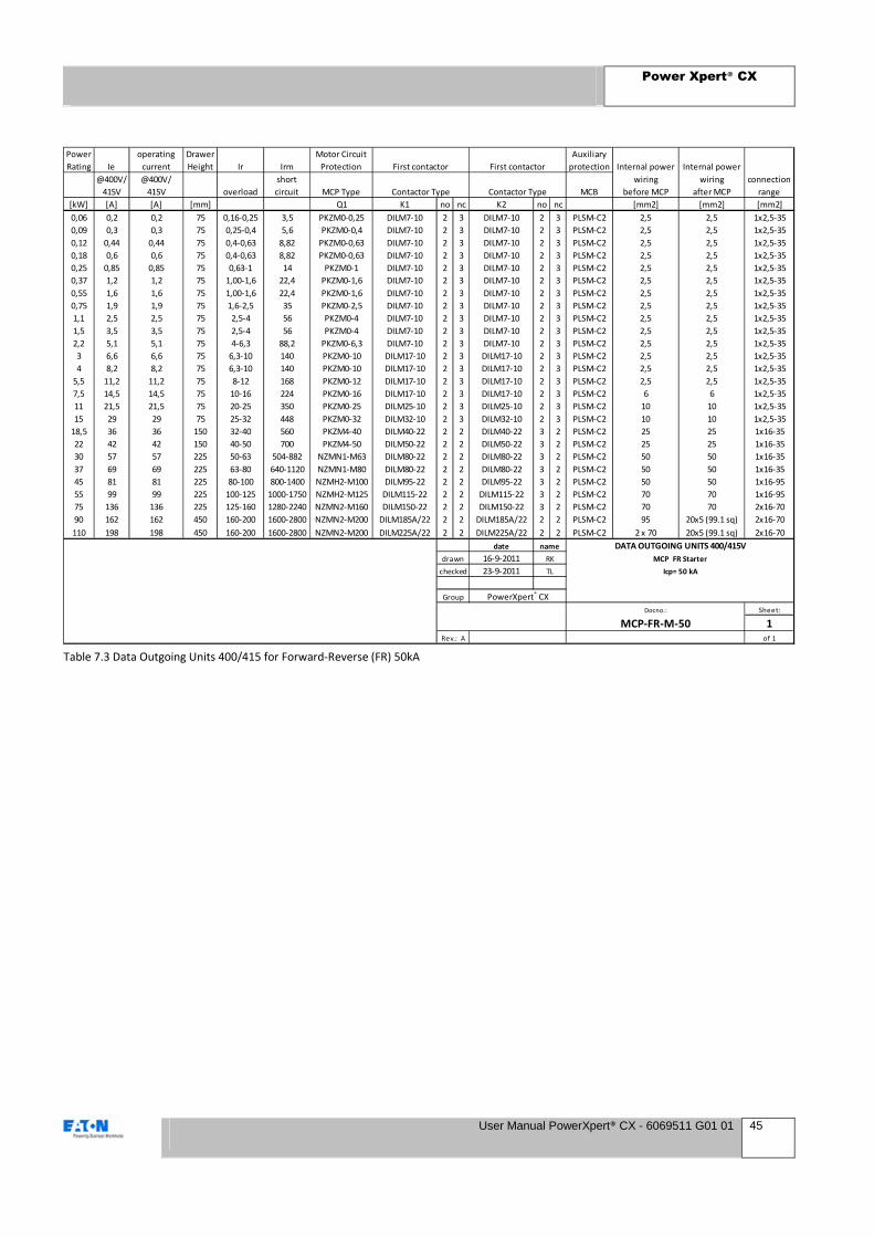
Power Xpert® CX
User Manual PowerXpert® CX - 6069511 G01 01 45
Power
Rating Ie
operating
current
Drawer
Height Ir Irm
Motor Circuit
Protection
Auxiliary
protection
@400V/
415V
@400V/
415V overload
short
circuit MCP Type MCB
[kW] [A] [A] [mm] Q1 K1 no nc K2 no nc [mm2] [mm2] [mm2]
0,06 0,2 0,2 75 0,16-0,25 3,5 PKZM0-0,25 DILM7-10 2 3 DILM7-10 2 3 PLSM-C2 2,5 2,5 1x2,5-35
0,09 0,3 0,3 75 0,25-0,4 5,6 PKZM0-0,4 DILM7-10 2 3 DILM7-10 2 3 PLSM-C2 2,5 2,5 1x2,5-35
0,12 0,44 0,44 75 0,4-0,63 8,82 PKZM0-0,63 DILM7-10 2 3 DILM7-10 2 3 PLSM-C2 2,5 2,5 1x2,5-35
0,18 0,6 0,6 75 0,4-0,63 8,82 PKZM0-0,63 DILM7-10 2 3 DILM7-10 2 3 PLSM-C2 2,5 2,5 1x2,5-35
0,25 0,85 0,85 75 0,63-1 14 PKZM0-1 DILM7-10 2 3 DILM7-10 2 3 PLSM-C2 2,5 2,5 1x2,5-35
0,37 1,2 1,2 75 1,00-1,6 22,4 PKZM0-1,6 DILM7-10 2 3 DILM7-10 2 3 PLSM-C2 2,5 2,5 1x2,5-35
0,55 1,6 1,6 75 1,00-1,6 22,4 PKZM0-1,6 DILM7-10 2 3 DILM7-10 2 3 PLSM-C2 2,5 2,5 1x2,5-35
0,75 1,9 1,9 75 1,6-2,5 35 PKZM0-2,5 DILM7-10 2 3 DILM7-10 2 3 PLSM-C2 2,5 2,5 1x2,5-35
1,1 2,5 2,5 75 2,5-4 56 PKZM0-4 DILM7-10 2 3 DILM7-10 2 3 PLSM-C2 2,5 2,5 1x2,5-35
1,5 3,5 3,5 75 2,5-4 56 PKZM0-4 DILM7-10 2 3 DILM7-10 2 3 PLSM-C2 2,5 2,5 1x2,5-35
2,2 5,1 5,1 75 4-6,3 88,2 PKZM0-6,3 DILM7-10 2 3 DILM7-10 2 3 PLSM-C2 2,5 2,5 1x2,5-35
3 6,6 6,6 75 6,3-10 140 PKZM0-10 DILM17-10 2 3 DILM17-10 2 3 PLSM-C2 2,5 2,5 1x2,5-35
4 8,2 8,2 75 6,3-10 140 PKZM0-10 DILM17-10 2 3 DILM17-10 2 3 PLSM-C2 2,5 2,5 1x2,5-35
5,5 11,2 11,2 75 8-12 168 PKZM0-12 DILM17-10 2 3 DILM17-10 2 3 PLSM-C2 2,5 2,5 1x2,5-35
7,5 14,5 14,5 75 10-16 224 PKZM0-16 DILM17-10 2 3 DILM17-10 2 3 PLSM-C2 6 6 1x2,5-35
11 21,5 21,5 75 20-25 350 PKZM0-25 DILM25-10 2 3 DILM25-10 2 3 PLSM-C2 10 10 1x2,5-35
15 29 29 75 25-32 448 PKZM0-32 DILM32-10 2 3 DILM32-10 2 3 PLSM-C2 10 10 1x2,5-35
18,5 36 36 150 32-40 560 PKZM4-40 DILM40-22 2 2 DILM40-22 3 2 PLSM-C2 25 25 1x16-35
22 42 42 150 40-50 700 PKZM4-50 DILM50-22 2 2 DILM50-22 3 2 PLSM-C2 25 25 1x16-35
30 57 57 225 50-63 504-882 NZMN1-M63 DILM80-22 2 2 DILM80-22 3 2 PLSM-C2 50 50 1x16-35
37 69 69 225 63-80 640-1120 NZMN1-M80 DILM80-22 2 2 DILM80-22 3 2 PLSM-C2 50 50 1x16-35
45 81 81 225 80-100 800-1400 NZMH2-M100 DILM95-22 2 2 DILM95-22 3 2 PLSM-C2 50 50 1x16-95
55 99 99 225 100-125 1000-1750 NZMH2-M125 DILM115-22 2 2 DILM115-22 3 2 PLSM-C2 70 70 1x16-95
75 136 136 225 125-160 1280-2240 NZMN2-M160 DILM150-22 2 2 DILM150-22 3 2 PLSM-C2 70 70 2x16-70
90 162 162 450 160-200 1600-2800 NZMN2-M200 DILM185A/22 2 2 DILM185A/22 2 2 PLSM-C2 95 20x5 (99.1 sq) 2x16-70
110 198 198 450 160-200 1600-2800 NZMN2-M200 DILM225A/22 2 2 DILM225A/22 2 2 PLSM-C2 2 x 70 20x5 (99.1 sq) 2x16-70
date
16-9-2011
23-9-2011
Sheet:
1of 1
name
RK
TL
PowerXpert® CXGroup
Docno.:
MCP-FR-M-50Rev.: A
drawn MCP FR Starter
checked Icp= 50 kA
First contactor Internal power
wiring
before MCP
Internal power
wiring
after MCP
connection
rangeContactor Type
DATA OUTGOING UNITS 400/415V
First contactor
Contactor Type
Table 7.3 Data Outgoing Units 400/415 for Forward-Reverse (FR) 50kA

Power Xpert® CX
User Manual PowerXpert® CX - 6069511 G01 01 46
Power
Rating Ie
operating
current
Drawer
Height Ir Irm
Motor Circuit
Protection
Auxiliary
protection
@400V/
415V
@400V/
415V overload
short
circuit MCP Type MCB
[kW] [A] [A] [mm] Q1 K1 no nc K2 no nc [mm2] [mm2] [mm2]
0,06 0,2 0,2 75 0,16-0,25 3,5 PKZM0-0,25 DILM7-10 2 3 DILM7-10 2 3 PLSM-C2 2,5 2,5 1x2,5-35
0,09 0,3 0,3 75 0,25-0,4 5,6 PKZM0-0,4 DILM7-10 2 3 DILM7-10 2 3 PLSM-C2 2,5 2,5 1x2,5-35
0,12 0,44 0,44 75 0,4-0,63 8,82 PKZM0-0,63 DILM7-10 2 3 DILM7-10 2 3 PLSM-C2 2,5 2,5 1x2,5-35
0,18 0,6 0,6 75 0,4-0,63 8,82 PKZM0-0,63 DILM7-10 2 3 DILM7-10 2 3 PLSM-C2 2,5 2,5 1x2,5-35
0,25 0,85 0,85 75 0,63-1 14 PKZM0-1 DILM7-10 2 3 DILM7-10 2 3 PLSM-C2 2,5 2,5 1x2,5-35
0,37 1,2 1,2 75 1,00-1,6 22,4 PKZM0-1,6 DILM7-10 2 3 DILM7-10 2 3 PLSM-C2 2,5 2,5 1x2,5-35
0,55 1,6 1,6 75 1,00-1,6 22,4 PKZM0-1,6 DILM7-10 2 3 DILM7-10 2 3 PLSM-C2 2,5 2,5 1x2,5-35
0,75 1,9 1,9 75 1,6-2,5 35 PKZM0-2,5 DILM7-10 2 3 DILM7-10 2 3 PLSM-C2 2,5 2,5 1x2,5-35
1,1 2,5 2,5 75 2,5-4 56 PKZM0-4 DILM7-10 2 3 DILM7-10 2 3 PLSM-C2 2,5 2,5 1x2,5-35
1,5 3,5 3,5 75 2,5-4 56 PKZM0-4 DILM7-10 2 3 DILM7-10 2 3 PLSM-C2 2,5 2,5 1x2,5-35
2,2 5,1 5,1 75 4-6,3 88,2 PKZM0-6,3 DILM7-10 2 3 DILM7-10 2 3 PLSM-C2 2,5 2,5 1x2,5-35
3 6,6 6,6 75 3,0-12 168 PKE12/XTU-12 DILM17-10 2 3 DILM17-10 2 3 PLSM-C2 2,5 2,5 1x2,5-35
4 8,2 8,2 75 3,0-12 168 PKE12/XTU-12 DILM17-10 2 3 DILM17-10 2 3 PLSM-C2 2,5 2,5 1x2,5-35
5,5 11,2 11,2 75 3,0-12 168 PKE12/XTU-12 DILM17-10 2 3 DILM17-10 2 3 PLSM-C2 2,5 2,5 1x2,5-35
7,5 14,5 14,5 75 8-32 448 PKE32/XTU-32 DILM17-10 2 3 DILM17-10 2 3 PLSM-C2 2,5 2,5 1x2,5-35
11 21,5 21,5 75 8-32 448 PKE32/XTU-32 DILM25-10 2 3 DILM25-10 2 3 PLSM-C2 10 10 1x2,5-35
15 29 29 75 8-32 448 PKE32/XTU-32 DILM32-10 2 3 DILM32-10 2 3 PLSM-C2 10 10 1x2,5-35
18,5 36 36 225 32-40 320-560 NZMH2-M40 DILM80-22 2 2 DILM80-22 3 2 PLSM-C2 16 16 1x16-35
22 42 42 225 40-50 400-700 NZMH2-M50 DILM80-22 2 2 DILM80-22 3 2 PLSM-C2 25 25 1x16-35
30 57 57 225 50-63 504-882 NZMH2-M63 DILM80-22 2 2 DILM80-22 3 2 PLSM-C2 25 25 1x16-35
37 69 69 225 63-80 640-1120 NZMH2-M80 DILM80-22 2 2 DILM80-22 3 2 PLSM-C2 50 50 1x16-35
45 81 81 225 80-100 800-1400 NZMH2-M100 DILM95-22 2 2 DILM95-22 3 2 PLSM-C2 50 50 1x16-95
55 99 99 225 100-125 1000-1750 NZMH2-M125 DILM115-22 2 2 DILM115-22 3 2 PLSM-C2 70 70 1x16-95
75 136 136 225 125-160 1280-2240 NZMH2-M160 DILM150-22 2 2 DILM150-22 3 2 PLSM-C2 70 70 2x16-70
90 162 162 450 160-200 1600-2800 NZMH2-M200 DILM185A/22 2 2 DILM185A/22 3 2 PLSM-C2 95 20x5 (99.1 sq) 2x16-70
110 198 198 450 160-200 1600-2800 NZMH2-M200 DILM225A/22 2 2 DILM225A/22 3 2 PLSM-C2 2 x 70 20x5 (99.1 sq) 2x16-70
date
16-9-2011
23-9-2011
Sheet:
1of 1
MCP-FR-M-80Rev.: A
Group PowerXpert® CX
Docno.:
checked TL Icp= 80 kA
name DATA OUTGOING UNITS 400/415V
drawn RK MCP FR Starter
First contactor First contactor Internal power
wiring
before MCP
Internal power
wiring
after MCP
connection
rangeContactor Type Contactor Type
Table 7.4 Data Outgoing Units 400/415 for Forward-Reverse (FR) 80kA
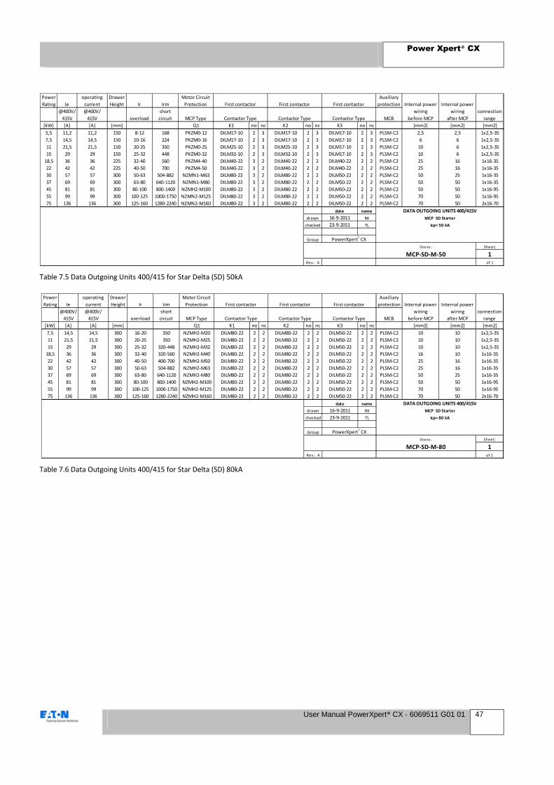
Power Xpert® CX
User Manual PowerXpert® CX - 6069511 G01 01 47
Power
Rating Ie
operating
current
Drawer
Height Ir Irm
Motor Circuit
Protection
Auxiliary
protection
@400V/
415V
@400V/
415V overload
short
circuit MCP Type MCB
[kW] [A] [A] [mm] Q1 K1 no nc K2 no nc K3 no nc [mm2] [mm2] [mm2]
5,5 11,2 11,2 150 8-12 168 PKZM0-12 DILM17-10 2 3 DILM17-10 2 3 DILM17-10 2 3 PLSM-C2 2,5 2,5 1x2,5-35
7,5 14,5 14,5 150 10-16 224 PKZM0-16 DILM17-10 2 3 DILM17-10 2 3 DILM17-10 2 3 PLSM-C2 6 6 1x2,5-35
11 21,5 21,5 150 20-25 350 PKZM0-25 DILM25-10 2 3 DILM25-10 2 3 DILM17-10 2 3 PLSM-C2 10 6 1x2,5-35
15 29 29 150 25-32 448 PKZM0-32 DILM32-10 2 3 DILM32-10 2 3 DILM17-10 2 3 PLSM-C2 10 6 1x2,5-35
18,5 36 36 225 32-40 560 PKZM4-40 DILM40-22 3 2 DILM40-22 2 2 DILM40-22 2 2 PLSM-C2 25 16 1x16-35
22 42 42 225 40-50 700 PKZM4-50 DILM40-22 3 2 DILM40-22 2 2 DILM40-22 2 2 PLSM-C2 25 16 1x16-35
30 57 57 300 50-63 504-882 NZMN1-M63 DILM80-22 3 2 DILM80-22 2 2 DILM50-22 2 2 PLSM-C2 50 25 1x16-35
37 69 69 300 63-80 640-1120 NZMN1-M80 DILM80-22 3 2 DILM80-22 2 2 DILM50-22 2 2 PLSM-C2 50 50 1x16-35
45 81 81 300 80-100 800-1400 NZMH2-M100 DILM80-22 3 2 DILM80-22 2 2 DILM50-22 2 2 PLSM-C2 50 50 1x16-95
55 99 99 300 100-125 1000-1750 NZMN2-M125 DILM80-22 3 2 DILM80-22 2 2 DILM50-22 2 2 PLSM-C2 70 50 1x16-95
75 136 136 300 125-160 1280-2240 NZMN2-M160 DILM80-22 3 2 DILM80-22 2 2 DILM50-22 2 2 PLSM-C2 70 50 2x16-70
date
16-9-2011
23-9-2011
Sheet:
1of 1
MCP-SD-M-50Rev.: A
First contactor
Contactor Type
Group PowerXpert® CX
Docno.:
checked TL Icp= 50 kA
name DATA OUTGOING UNITS 400/415V
drawn RK MCP SD Starter
First contactor First contactor Internal power
wiring
before MCP
Internal power
wiring
after MCP
connection
rangeContactor Type Contactor Type
Table 7.5 Data Outgoing Units 400/415 for Star Delta (SD) 50kA
Power
Rating Ie
operating
current
Drawer
Height Ir Irm
Motor Circuit
Protection
Auxiliary
protection
@400V/
415V
@400V/
415V overload
short
circuit MCP Type MCB
[kW] [A] [A] [mm] Q1 K1 no nc K2 no nc K3 no nc [mm2] [mm2] [mm2]
7,5 14,5 14,5 300 16-20 350 NZMH2-M20 DILM80-22 2 2 DILM80-22 2 2 DILM50-22 2 2 PLSM-C2 10 10 1x2,5-35
11 21,5 21,5 300 20-25 350 NZMH2-M25 DILM80-22 2 2 DILM80-22 2 2 DILM50-22 2 2 PLSM-C2 10 10 1x2,5-35
15 29 29 300 25-32 320-448 NZMH2-M32 DILM80-22 2 2 DILM80-22 2 2 DILM50-22 2 2 PLSM-C2 10 10 1x2,5-35
18,5 36 36 300 32-40 320-560 NZMH2-M40 DILM80-22 2 2 DILM80-22 2 2 DILM50-22 2 2 PLSM-C2 16 10 1x16-35
22 42 42 300 40-50 400-700 NZMH2-M50 DILM80-22 2 2 DILM80-22 2 2 DILM50-22 2 2 PLSM-C2 25 16 1x16-35
30 57 57 300 50-63 504-882 NZMH2-M63 DILM80-22 2 2 DILM80-22 2 2 DILM50-22 2 2 PLSM-C2 25 16 1x16-35
37 69 69 300 63-80 640-1120 NZMH2-M80 DILM80-22 2 2 DILM80-22 2 2 DILM50-22 2 2 PLSM-C2 50 25 1x16-35
45 81 81 300 80-100 800-1400 NZMH2-M100 DILM80-22 2 2 DILM80-22 2 2 DILM50-22 2 2 PLSM-C2 50 50 1x16-95
55 99 99 300 100-125 1000-1750 NZMH2-M125 DILM80-22 2 2 DILM80-22 2 2 DILM50-22 2 2 PLSM-C2 70 50 1x16-95
75 136 136 300 125-160 1280-2240 NZMH2-M160 DILM80-22 2 2 DILM80-22 2 2 DILM50-22 2 2 PLSM-C2 70 50 2x16-70
date
16-9-2011
23-9-2011
Sheet:
1of 1
MCP-SD-M-80Rev.: A
Group PowerXpert® CX
Docno.:
checked TL Icp= 80 kA
name DATA OUTGOING UNITS 400/415V
drawn RK MCP SD Starter
First contactor First contactor First contactor Internal power
wiring
before MCP
Internal power
wiring
after MCP
connection
rangeContactor Type Contactor Type Contactor Type
Table 7.6 Data Outgoing Units 400/415 for Star Delta (SD) 80kA

Power Xpert® CX
User Manual PowerXpert® CX - 6069511 G01 01 48
8 Accessories And Spare Parts
8.1 List of available accessories and spare
parts
The following accessories can also be supplied for Power Xpert
CX switchgear
8.1.1 Structures
Rear Wall Art. Nr
600mm width IP31 284361
800mm width IP31 284362
1000mm width IP31 284363
1200mm width IP31 284364
600mm width IP55 284356
800mm width IP55 284357
1000mm width IP55 284358
1200mm width IP55 284359
Side Wall Art. Nr
600mm depth 283857
800mm depth 283858
Cableway door Art. Nr
400mm width IP31 151670
400mm width IP55 284183
600mm width IP31 151671
600mm width IP55 284185
600mm high door (XP column) Art. Nr
600mm width IP31 284206
800mm width IP31 284207
1000mm width IP31 285507
600mm width IP55 284195
800mm width IP55 284196
1000mm width IP55 285506
Raingutter Art. Nr
1000mm width 155542
1200mm width 155543
Main Power terminal (cable way) WAGO Art. Nr
Main Power WAGO terminal (cable way) 6068310
Auxiliary terminal (cable way) WAGO Art. Nr
Auxiliary terminal (minimum qty = 40) 6067927
Shutter Art. Nr
MCC Shutter accessory (minimum qty = 25) 151217
Lifting Eyes Art. Nr
Lifting Eyes (set of 4) 283855
8.1.2 Withdrawable Units
Main Incoming Contacts EATON Art. Nr
100A 3P 151354
315A 3P 151355
630A 3P 151356
100A 4P 151357
315A 4P 151358
630A 4P 151359
Main Outgoing Contacts HARTING Art. Nr
Up to 40A 3P (cable 2.5 - 8) 152649
Up to 40A 3P (cable 6 - 10) 152650
Up to 100A 3P (cable 10-25) 152651
Up to 100A 3P (cable 16-35) 152652
Up to 200A 3P (cable 25-40) 152653
Up to 200A 3P (cable 40-70) 152654
Up to 200A 4P (cable 25-40) 152655
Up to 200A 4P (cable 40-70) 152656
Auxiliary contacts XILCO Art. Nr
Auxiliary contacts 155540
Stopper for auxiliary contact 155541
Mechanical Interlock Art. Nr
75mm 155247
150mm with PKZ/PKE 155248
150mm - 300mm with NZM 155249
450mm 155260
Rotary Handle Art. Nr
PKZ0/PKZ4 164297
PKE 164299
NZM1 271504
NZM2 279393
NZM3 279394

Power Xpert® CX
User Manual PowerXpert® CX - 6069511 G01 01 49
9 Appendix
9.1 General
This user manual is part of the information pack
compiled whenever equipment is supplied and
consists of the following parts
Information on the folder(s):
• Project title
• Name of the installation
• Type of installation (key data such as voltage,
current etc.)
• Client order number
• Eaton name and order number
• Eaton contact address for fault reporting: name,
telephone number, fax number
• Date of issue
• Table of contents
Diagram pack, including:
• Single line diagram
• Floor plan drawings with dimensions,
measurements and weights

10 Comment form
Eaton low-voltage switchgear type Power Xpert CX
If you have any comments on this manual or suggestions for improving this manual, please forward them to us on this
form.
Is this manual YES NO
• Comprehensive enough? � �
• Well set out? � �
• Clear? � �
• Adequately illustrated? � �
• Is this manual satisfactory � �
If not, how could the manual be improved?
Please give specific points or examples.
Your name:
Your position:
Company name:
Address: