pr100 user manual
TRANSCRIPT

R&S® PR100 Portable Receiver Manual
Manu
al

© 2008 Rohde & Schwarz GmbH & Co. KG 81671 Munich, Germany Printed in Germany – Subject to change – Data without tolerance limits is not binding. R&S® is a registered trademark of Rohde & Schwarz GmbH & Co. KG. Trade names are trademarks of the owners. The following abbreviations are used throughout this manual: R&S® PR100 is abbreviated as R&S PR100.
Index:
Index:................................................................................................................................................ 3 1 Performance Check .................................................................................................................. 8
1.1 Symbols and safety labels.................................................................................... 9 1.2 Tags and their meaning........................................................................................ 9 1.3 Basic safety instructions .................................................................................... 10
2 Quality certificate................................................................................................................... 12 3 EC certificate.......................................................................................................................... 13 4 Support center address ........................................................................................................... 14 5 Operating principle................................................................................................................. 15 6 Set-up ..................................................................................................................................... 20
6.1 Front view.......................................................................................................... 20 6.2 Top view ............................................................................................................ 21 6.3 Unpacking the instrument.................................................................................. 21 6.4 Setting up the instrument ................................................................................... 22 6.5 Inserting the battery ........................................................................................... 23 6.6 Connecting to the power supply ........................................................................ 23 6.7 Charging the Battery.......................................................................................... 24 6.8 Switching on the monitoring receiver................................................................ 25 6.9 Ambient and operating conditions..................................................................... 26 6.10 Preventive maintenance ..................................................................................... 26 6.11 Monitoring receiver connectors ......................................................................... 26 6.12 Software update ................................................................................................. 33
6.12.1 Option code activation ....................................................................................... 34 7 Configuration Menus ............................................................................................................. 35
7.1 RX Configuration Menu .................................................................................... 35 7.1.1 General............................................................................................................... 35 7.1.2 Antenna (only with option Field Strength Measurement) ................................. 39 7.1.3 Tone ................................................................................................................... 41 7.1.4 Measure.............................................................................................................. 42 7.1.5 BFO (CW only) ................................................................................................. 44 7.1.6 Direct Conversion Threshold............................................................................. 45 7.1.7 Inputs / Outputs.................................................................................................. 45
7.2 Scan Configuration Menu.................................................................................. 46 7.2.1 Frequency Scan.................................................................................................. 46
7.3 Memory Scan..................................................................................................... 48 7.3.1 Scan Options...................................................................................................... 50
7.4 Display............................................................................................................... 53 7.4.1 RX Screen .......................................................................................................... 53 7.4.2 IF-PAN Screen................................................................................................... 54 7.4.3 RF-PAN Screen ................................................................................................. 56 7.4.4 Waterfall Screen ................................................................................................ 57
7.5 General Configuration Menu............................................................................. 60 7.5.1 General............................................................................................................... 60 7.5.2 Local Settings .................................................................................................... 61 7.5.3 Display............................................................................................................... 62 7.5.4 Keys ................................................................................................................... 62 7.5.5 Audio ................................................................................................................. 64
7.5.6 LAN ................................................................................................................... 66 7.6 Memory Configuration Menu............................................................................ 69
7.6.1 Direct Save & Auto Save................................................................................... 69 7.7 Antenna Configuration Menu ............................................................................ 71
8 SCPI Interface ........................................................................................................................ 72 8.1 Document Outline.............................................................................................. 72 8.2 Legend ............................................................................................................... 72
Abbreviations Used................................................................................................................ 72 9 SCPI Commands .................................................................................................................... 73
9.1 SCPI introduction .............................................................................................. 73 9.1.1 Common Command Structure ........................................................................... 74 9.1.2 Device-Specific Command Structure ................................................................ 74 9.1.3 Structure of a command line.............................................................................. 75 9.1.4 Responses to queries.......................................................................................... 76 9.1.5 Parameters.......................................................................................................... 77 Syntax Elements..................................................................................................................... 79
9.2 Status Reporting................................................................................................. 79 Structure of an SCPI status register ....................................................................................... 80 9.2.1 Description of the status registers...................................................................... 83 9.2.2 Use of the Status Reporting System .................................................................. 91 9.2.3 Resetting values of the status reporting system................................................. 93
9.3 Error Messages .................................................................................................. 93 9.4 Commands Description ..................................................................................... 98
9.4.1 Notation ............................................................................................................. 98 9.4.2 Common Commands ......................................................................................... 99
10 Instrument Behaviour ...................................................................................... 101 10.1 Error Situations ................................................................................................ 102 10.2 Ranging and Rounding .................................................................................... 102 10.3 Value Representation....................................................................................... 103 10.4 Default Values ................................................................................................. 103 10.5 Instrument States ............................................................................................. 103
10.5.1 Introduction...................................................................................................... 103 10.5.2 MR States......................................................................................................... 103
11 Commands Reference ...................................................................................... 106 11.1 Common Commands ....................................................................................... 106 11.2 ABORt subsystem ........................................................................................... 107 11.3 CALCulate subsystem ..................................................................................... 107 11.4 DIAGnostic subsystem .................................................................................... 112 11.5 DISPlay subsystem .......................................................................................... 113 11.6 FORMat subsystem ......................................................................................... 132 11.7 INITiate subsystem.......................................................................................... 135 11.8 INPut subsystem .............................................................................................. 137 11.9 MEASure subsystem ....................................................................................... 138 11.10 MEMory subsystem......................................................................................... 140
11.10.1 Memory list subsystem .................................................................................... 147 11.10.2 Memory save subsystem.................................................................................. 149
11.11 MMEMory subsystem ..................................................................................... 152 11.12 OUTPut subsystem .......................................................................................... 160 11.13 Program preset subsystem ............................................................................... 173 11.14 SENSe Subsystem ........................................................................................... 176
11.14.1 Sense Memory Scan subsystem MSC ............................................................. 201

11.14.2 Sense Panorama Scan subsystem PSC ............................................................ 211 Sense Frequency Scan subsystem SWE............................................................................... 217
11.15 STATus subsystem .......................................................................................... 224 11.16 SYSTem subsystem ......................................................................................... 229 11.17 TRACe|DATA subsystem ............................................................................... 246 11.18 TRACe|DATA:UDP subsystem ...................................................................... 259
12 UDP Data Streams........................................................................................... 266 12.1 Stream Packet Structure................................................................................... 266 12.2 Audio ............................................................................................................... 270 12.3 FScan ............................................................................................................... 272 12.4 MScan .............................................................................................................. 274 12.5 CW................................................................................................................... 275 12.6 IFPan................................................................................................................ 276 12.7 IF...................................................................................................................... 277 12.8 PSCAN ............................................................................................................ 279
13 Default Values ................................................................................................. 282 CALCulation subsystem .......................................................................................................... 282 13.1 DISPlay subsystem .......................................................................................... 282 13.2 FORMat subsystem ......................................................................................... 283 13.3 INPut subsystem .............................................................................................. 283 13.4 MEASurement subsystem ............................................................................... 283 13.5 MEMory subsystem......................................................................................... 283 13.6 OUTPut subsystem .......................................................................................... 283 13.7 SENSe subsystem ............................................................................................ 283 13.8 STATus subsystem .......................................................................................... 284 13.9 SYSTem subsystem ......................................................................................... 284 13.10 TRACe subsystem ........................................................................................... 284
R&S PR100 User Manual
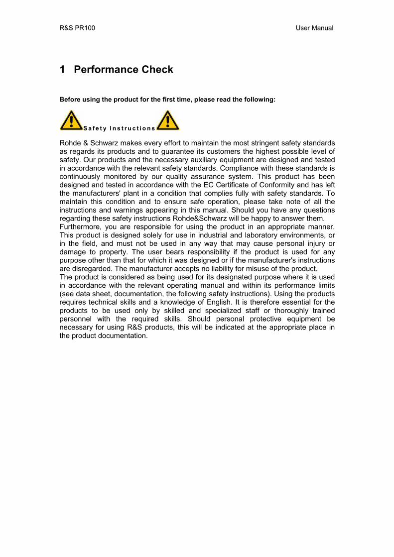
1 Performance Check
Before using the product for the first time, please read the following:
S a f e t y I n s t r u c t i o n s
Rohde & Schwarz makes every effort to maintain the most stringent safety standards as regards its products and to guarantee its customers the highest possible level of safety. Our products and the necessary auxiliary equipment are designed and tested in accordance with the relevant safety standards. Compliance with these standards is continuously monitored by our quality assurance system. This product has been designed and tested in accordance with the EC Certificate of Conformity and has left the manufacturers' plant in a condition that complies fully with safety standards. To maintain this condition and to ensure safe operation, please take note of all the instructions and warnings appearing in this manual. Should you have any questions regarding these safety instructions Rohde&Schwarz will be happy to answer them. Furthermore, you are responsible for using the product in an appropriate manner. This product is designed solely for use in industrial and laboratory environments, or in the field, and must not be used in any way that may cause personal injury or damage to property. The user bears responsibility if the product is used for any purpose other than that for which it was designed or if the manufacturer's instructions are disregarded. The manufacturer accepts no liability for misuse of the product. The product is considered as being used for its designated purpose where it is used in accordance with the relevant operating manual and within its performance limits (see data sheet, documentation, the following safety instructions). Using the products requires technical skills and a knowledge of English. It is therefore essential for the products to be used only by skilled and specialized staff or thoroughly trained personnel with the required skills. Should personal protective equipment be necessary for using R&S products, this will be indicated at the appropriate place in the product documentation.

R&S PR100 User Manual
1.1 Symbols and safety labels
Compliance with safety instructions will help prevent personal injury or damage caused by hazards of any kind. It is therefore essential to carefully read and comply with the following safety instructions before commissioning the product. It is also absolutely vital to comply with additional safety instructions relating to personal safety which appear in other sections of the documentation. In these safety instructions, the word "product" refers to all goods sold and distributed by Rohde&Schwarz, including all instruments, systems and accessories.
1.2 Tags and their meaning DANGER Indicates a hazard area that carries a high risk of danger for users. The hazard area can
cause death or serious injuries. WARNING Indicates a hazard area that carries a medium risk of danger for users. The hazazrd
area can cause death or serious injuries. CAUTION Indicates a hazard area that carries a slight risk of danger for users. The hazard area
can cause minor injuries. ATTENTION This tag indicates the possibility of incorrect use which may cause damage to the
product. NOTE This tag indicates a situation where the user should take special care when operating
the product but which will not damage the product.
R&S PR100 User Manual
1.3 Basic safety instructions 1. The product should be operated only under the operating conditions and in the situations specified by the manufacturer; its ventilation must not be obstructed during operation. Unless otherwise specified, the following requirements apply to R&S products: IP protection 2X, pollution level 2, excess voltage category 2, for indoor use only, maximum operating altitude 2000 meters above sea level 2. Applicable local or national safety regulations and accident prevention rules must be observed when performing any operations. The product should only be opened by authorized, specially trained personnel. Prior to carrying out any work on the product or opening the product, it must be disconnected from the mains power supply. Any adjustments, replacement of parts, maintenance or repairs must only be carried out by specialist electricians authorized by R&S. Original parts only should be used to replace safety-related components (e.g. power switches, power transformers or fuses). A safety test must always be carried out after safety-related components have been replaced (visual inspection, ground/earth test, insulation resistance and leakage current measurements, function test). 3. As with all manufactured goods, the use of substances that may cause an allergic reaction (allergens), such as aluminum, cannot be ruled out. Should you develop an allergic reaction (such as a skin rash, frequent sneezing, red eyes or breathing difficulties) when using R&S products, consult a doctor immediately to determine the cause. 4. For certain functions, some products, such as HF radio equipment, can produce a high level of electromagnetic radiation. Given that unborn children require increased protection, appropriate measures should be taken to protect pregnant women. People with pacemakers may also be harmed by electromagnetic radiation. Employers are required to assess workplaces where there is a specific risk of exposure to radiation and, where necessary, take measures to avert the danger. 5. Special training and a high level of concentration is needed to operate the products. Disabled people should only use the products if it is certain that there will be no impairment due to the nature of their disability when operating the products. 6. Before switching on the product, ensure that the rated voltage setting on the product matches the rated voltage of the mains supply. The product's mains fuse should also be changed if it is necessary to alter the voltage setting. 7. In the case of safety class I products with a flexible power cord and connector, operation is only permitted using sockets with an earth/ground contact and a protective earth/ground connection. 8. Intentionally breaking the protective earth/ground connection, either in the feed line or in the product itself, is not permitted; doing so may result in an electric shock hazard from the product. Where extension cables or connector strips are used, they must be checked on a regular basis to ensure that they are safe to use. 9. If the product is not equipped with a power switch for disconnection from the mains supply, the plug on the connecting cable is to be regarded as the disconnecting device. In such cases, you must ensure that the mains plug can be easily reached and is accessible at all times (length of the connecting cable approx. 2m). Function or electronic switches are not suitable for disconnecting the mains supply. If products
R&S PR100 User Manual
without a mains switch are integrated into racks or systems, a disconnecting device must be provided at the system level. 10. Never use the product if the power cable is damaged. Take appropriate safety measures and carefully lay the power cable to ensure that the latter cannot be damaged and that no one can be hurt, for example by tripping over the cable or receiving an electric shock. 11. The product may be operated only from TN/TT mains power networks with a maximum 16A fuse. 12. Do not insert the plug into sockets that are dusty or dirty. Insert the plug firmly and all the way into the socket, otherwise there is a risk of sparks, fire and/or injury. 13. Do not overload any sockets, extension cables or connector strips; doing so may cause fire or electric shocks. 14. For circuit measurements with Vrms voltages above 30V, suitable measures (e.g. appropriate measuring equipment, fuses, current limiting, electrical separation, insulation, etc.) should be taken to avoid any hazards. 15. Ensure that any connections with computer equipment comply with IEC950/EN60950. 16. Never remove the cover or part of the housing while you are operating the product. This will expose circuits and components and may cause injury, fire or damage to the product. 17. If a product is to be permanently installed, the earth/ground connection on site and the product's earth/ground conductor must be connected before any other connection is made. The product must only be installed and connected by a specialist electrician. 18. For permanently installed equipment without built-in fuses, circuit breakers or similar protective devices, the mains circuit must be fuse-protected in such a way that users and products are sufficiently protected. 19. Do not insert any objects which are not designed for this purpose into the openings on the housing. Never pour any liquids onto or into the housing. This may cause a short circuit inside the product and/or electric shocks, fire or injury. 20. Take appropriate measures to protect against excess voltage caused by adverse weather conditions (e.g. thunderstorms) reaching the product, otherwise, operating personnel will be exposed to the risk of electric shocks. 21. R&S products are not protected against water penetration unless otherwise specified (see Point 1). If this is not observed there is a risk of electric shocks or damage to the product, which may also result in personal injury. 22. Never use the product in conditions where condensation has formed or may form in or on the product, for example when the product is moved from a cold to a warm environment. 23. Do not obstruct any slots or openings on the product, since these are necessary for ventilation and prevent the product from overheating. Do not place the product on

R&S PR100 User Manual
surfaces that are not rigid, such as sofas or carpets, or inside a closed housing, unless this is well ventilated. 24. Do not place the product on equipment that generates heat, such as a radiator or fan heater. The ambient temperature must not exceed the maximum temperature specified in the data sheet. 25. Batteries and storage batteries must not be exposed to high temperatures or fire. Store batteries and storage batteries out of the reach of children. If batteries or storage batteries are not replaced appropriately there is a risk of explosion (warning: lithium cells). Batteries and storage batteries must only be replaced with the corresponding R&S type batteries (see spare parts list). Batteries and storage batteries are classed as hazardous waste. Dispose of them only in specially marked containers. Comply with local regulations concerning waste disposal. Do not short-circuit batteries or storage batteries. 26. Please be aware that in the event of a fire, the product may emit toxic gases that can be harmful to your health. 27. Be aware of the weight of the product. Move the product carefully, as its weight may cause back or other physical injuries. 28. Do not place the product on surfaces, vehicles, cabinets or tables whose weight and stability make them unsuitable for this product. Always follow the manufacturer's installation instructions when installing the product and attaching it to objects or structures (e.g. walls and shelves). 29. Should you decide to use the product inside a vehicle, it is the sole responsibility of the driver to drive the vehicle safely. Secure the product properly inside the vehicle to prevent injury or damage in the event of an accident. Never use the product in a moving vehicle if doing so may distract the driver of the vehicle. The driver is always responsible for the safety of the vehicle; the manufacturer assumes no responsibility for accidents or collisions. 30. If a laser product (e.g. a CD/DVD drive) is integrated into an R&S product, do not use any settings or functions other than those described in the documentation. This may otherwise be hazardous to your health, since lasers may cause irreversible optical damage. Never attempt to take such products apart. Never look directly into the laser beam.
2 Quality certificate Dear Customer, Thank you for purchasing a Rohde & Schwarz product. This product is manufactured using state-of-the-art production methods. It is developed, produced and tested in accordance with the rules of our Quality Management System. The Rohde & Schwarz Quality Management System is ISO 9001 certified. Certified Quality System ISO 9001 DQS REG. NO 1954-04
R&S PR100 User Manual
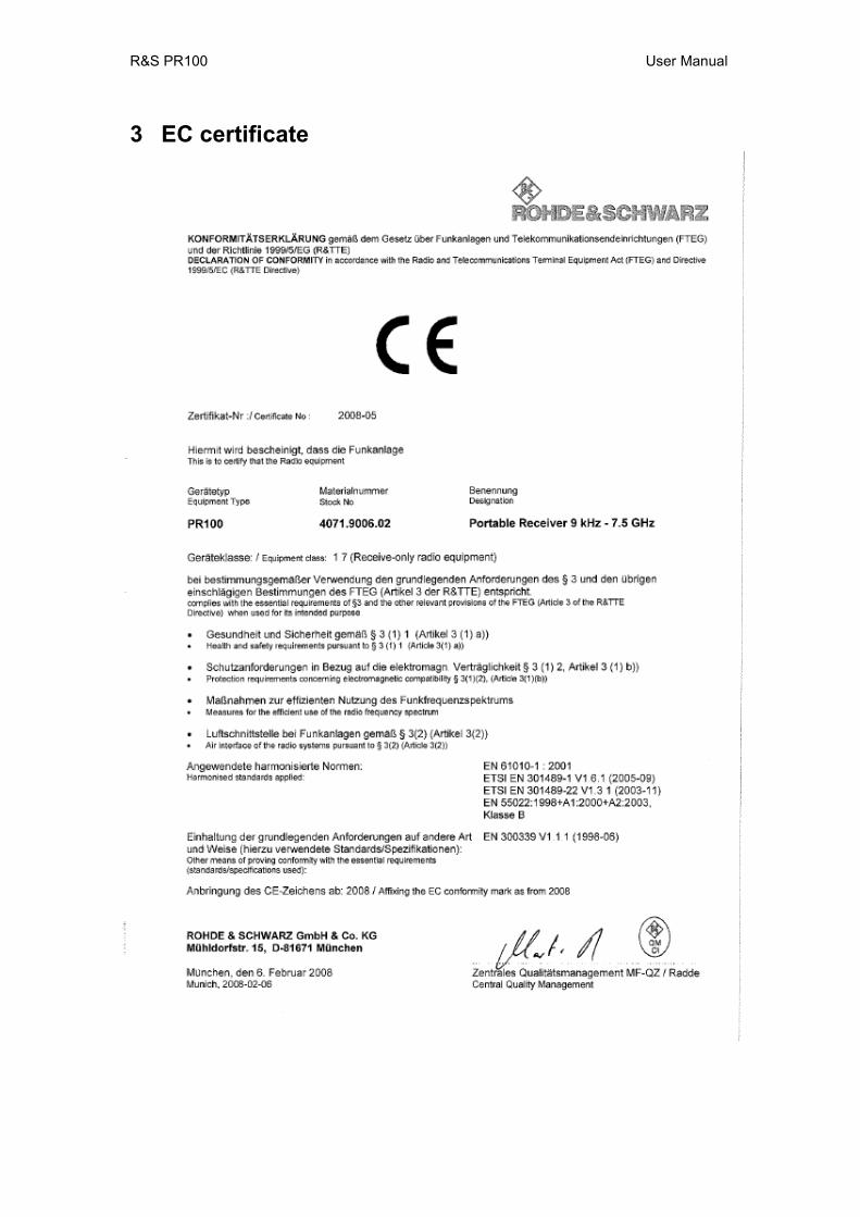
3 EC certificate
R&S PR100 User Manual
4 Support center address Should you have any questions regarding this Rohde & Schwarz instrument, please call our Support center hotline at Rohde & Schwarz Vertriebs-GmbH. Our team will be happy to answer your questions and work with you to find a solution. The hotline is open Monday to Friday between 8 a.m. and 5 p.m. Should you wish to contact us outside normal business hours, please leave a voice message or send us a fax or email. We will contact you as soon as possible. If you would like to receive information on modifications and updates for a specific instrument, please send us a short email stating which instrument. We will ensure that you regularly receive the latest information. Support center Tel: +49 180 512 42 42 Fax: +49 89 41 29 137 77 Email: [email protected]
R&S PR100 User Manual
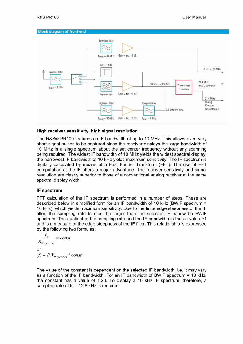
5 Operating principle Frontend
Starting from the antenna socket, the frequency in the signal path is limited to 8 GHz. Signal processing then takes place in three paths for three different frequency ranges. Signals from 9 kHz to 30 MHz are routed via a preamplifier directly to the A/D converter. Signals from 20 MHz to 3.5 GHz are taken to the IF section via a preselection and a preamplifier, or via an attenuator in the case of high signal levels. The preselection as well as the attenuator effectively protect the IF section against overloading. This is particularly important in this frequency range, where the maximum signal sum levels occur. Signals from 3.5 GHz to 8 GHz are taken to the IF section via a preamplifier. The three-stage IF section processes the signals from 20 MHz to 8 GHz for the subsequent A/D converter. To provide optimum instrument performance, only signals up to 7.5 GHz are processed in the subsequent stages. The uncontrolled 21.4 MHz IF can also be tapped ahead of the A/D converter via a BNC socket of the R&S®PR100 for further external processing. Digital signal processing After A/D conversion of the signal, the signal path is split up: In the first path, the IF spectrum is calculated by means of a digital downconverter (DDC), a digital bandpass filter and an FFT stage. The bandwidth of the bandpass filter can be selected between 10 kHz and 10 MHz. Before the IF spectrum is output on the display or via the LAN interface, results are postprocessed by means of the AVERAGE, MIN HOLD or MAX HOLD function as selected by the user. In the second path, the signal is processed for level measurement or demodulation. Here, too, the signal is taken via a DDC and a bandpass filter. To process the different signals with optimum signal-to-noise ratio, the receiver contains IF filters with demodulation bandwidths from 150 Hz to 500 kHz, which can be selected independently of the IF bandwidth. Prior to the level measurement, the absolute value of the level is determined and weighted by means of the AVERAGE, MAX PEAK, RMS or SAMPLE function, as selected by the user. The measured level is then output on the display or via the LAN interface. For the demodulation of analog signals, the complex baseband data is subjected to automatic gain control (AGC) or manual gain control (MGC) after the bandpass filter. It is then applied to the AM, FM, USB, LSB, ISB, PULSE or CW demodulation stage. The complex baseband data (I/Q data) of digital signals is directly output for further processing after the AGC/MGC stage.
The results obtained are available as digital data and can be output via the LAN interface as required for the particular task. Digital audio data are reconverted to analog signals for output via the loudspeaker.
R&S PR100 User Manual
High receiver sensitivity, high signal resolution The R&S® PR100 features an IF bandwidth of up to 10 MHz. This allows even very short signal pulses to be captured since the receiver displays the large bandwidth of 10 MHz in a single spectrum about the set center frequency without any scanning being required. The widest IF bandwidth of 10 MHz yields the widest spectral display; the narrowest IF bandwidth of 10 kHz yields maximum sensitivity. The IF spectrum is digitally calculated by means of a Fast Fourier Transform (FFT). The use of FFT computation at the IF offers a major advantage: The receiver sensitivity and signal resolution are clearly superior to those of a conventional analog receiver at the same spectral display width. IF spectrum FFT calculation of the IF spectrum is performed in a number of steps. These are described below in simplified form for an IF bandwidth of 10 kHz (BWIF spectrum = 10 kHz), which yields maximum sensitivity. Due to the finite edge steepness of the IF filter, the sampling rate fs must be larger than the selected IF bandwidth BWIF spectrum. The quotient of the sampling rate and the IF bandwidth is thus a value >1 and is a measure of the edge steepness of the IF filter. This relationship is expressed by the following two formulas:
constBf
IFspectrum
s =
or constBWf IFspectrums *=
The value of the constant is dependent on the selected IF bandwidth, i.e. it may vary as a function of the IF bandwidth. For an IF bandwidth of BWIF spectrum = 10 kHz, the constant has a value of 1.28. To display a 10 kHz IF spectrum, therefore, a sampling rate of fs = 12.8 kHz is required.

R&S PR100 User Manual
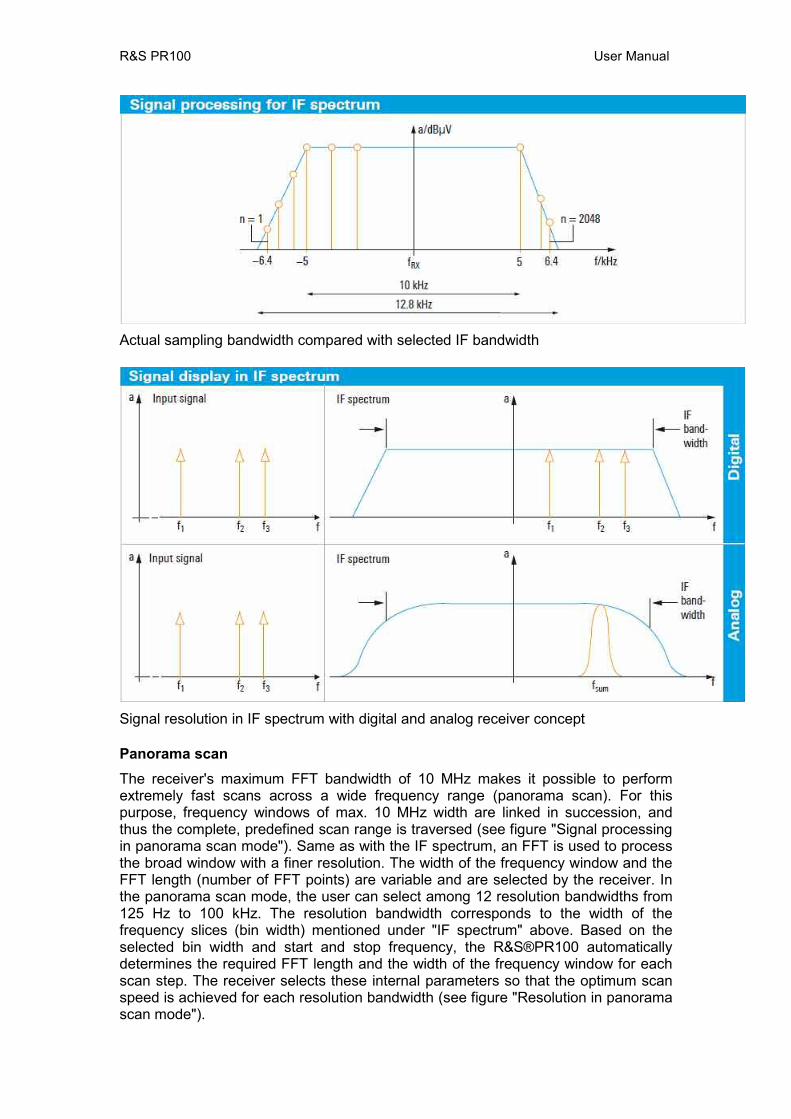
The R&S®PR100 uses an FFT length N of 2048 points to generate the IF spectrum. To calculate these points, the 12.8 kHz sampling band in the above example is divided into 2048 equidistant frequency slices, which are also referred to as “bins” (see figure "Signal processing for IF spectrum"). The bandwidth BWbin of the frequency slices is obtained as follows:
HzkHzfBW sbin 25.6
20488.12
2048===
This means that in the above example only the calculated bandwidth of 6.25 Hz for each bin has to be taken into account as the noise bandwidth in the calculation of the displayed average noise level (DANL) in accordance with the formula below (the effect of the window function (Blackman window) of the FFT is not considered here for simplicity's sake):
)/log(*10174 HzBWNFdBmDANL bin++−=
The quantity NF represents the overall noise figure of the receiver. The above example shows that, due to the use of the FFT, the actual resolution bandwidth (RBW) to be taken into account in DANL calculation is clearly smaller (i.e. BWbin) than would be expected for the wide display range of 10 kHz. Another advantage of the high spectral resolution used in the FFT calculation is that signals located close together (e.g. f1, f2, f3) can be captured and represented in the IF spectrum as discrete signals (see figure "Signal display in IF spectrum"). If, on an analog receiver, a resolution bandwidth equal to the set IF bandwidth were selected (RBW = BWIF spectrum), a sum signal fsum would be displayed instead of the three discrete signals f1, f2 and f3.
R&S PR100 User Manual
Actual sampling bandwidth compared with selected IF bandwidth
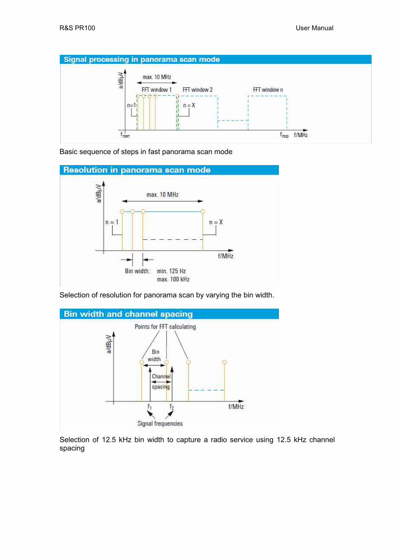
Signal resolution in IF spectrum with digital and analog receiver concept Panorama scan The receiver's maximum FFT bandwidth of 10 MHz makes it possible to perform extremely fast scans across a wide frequency range (panorama scan). For this purpose, frequency windows of max. 10 MHz width are linked in succession, and thus the complete, predefined scan range is traversed (see figure "Signal processing in panorama scan mode"). Same as with the IF spectrum, an FFT is used to process the broad window with a finer resolution. The width of the frequency window and the FFT length (number of FFT points) are variable and are selected by the receiver. In the panorama scan mode, the user can select among 12 resolution bandwidths from 125 Hz to 100 kHz. The resolution bandwidth corresponds to the width of the frequency slices (bin width) mentioned under "IF spectrum" above. Based on the selected bin width and start and stop frequency, the R&S®PR100 automatically determines the required FFT length and the width of the frequency window for each scan step. The receiver selects these internal parameters so that the optimum scan speed is achieved for each resolution bandwidth (see figure "Resolution in panorama scan mode").
R&S PR100 User Manual
Basic sequence of steps in fast panorama scan mode
Selection of resolution for panorama scan by varying the bin width.
Selection of 12.5 kHz bin width to capture a radio service using 12.5 kHz channel spacing
R&S PR100 User Manual
6 Set-up
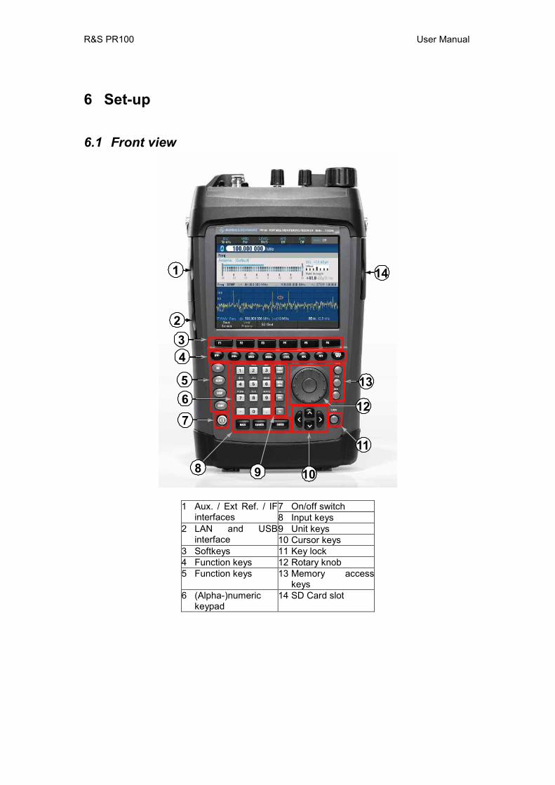
6.1 Front view
14
13
9
7
8 10
11
12
5
4
1
23
6
7 On/off switch 1 Aux. / Ext Ref. / IF interfaces 8 Input keys
9 Unit keys 2 LAN and USB interface 10 Cursor keys
3 Softkeys 11 Key lock 4 Function keys 12 Rotary knob 5 Function keys 13 Memory access
keys 6 (Alpha-)numeric
keypad 14 SD Card slot
R&S PR100 User Manual
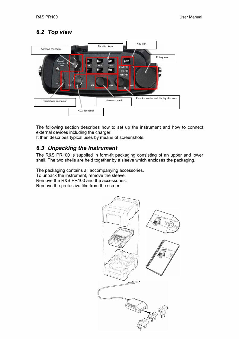
6.2 Top view
The following section describes how to set up the instrument and how to connect external devices including the charger. It then describes typical uses by means of screenshots.
6.3 Unpacking the instrument The R&S PR100 is supplied in form-fit packaging consisting of an upper and lower shell. The two shells are held together by a sleeve which encloses the packaging. The packaging contains all accompanying accessories. To unpack the instrument, remove the sleeve. Remove the R&S PR100 and the accessories. Remove the protective film from the screen.
Headphone connector
Antenna connector Function keys
Key lock
Rotary knob
Function control and display elements Volume control
AUX connector
R&S PR100 User Manual
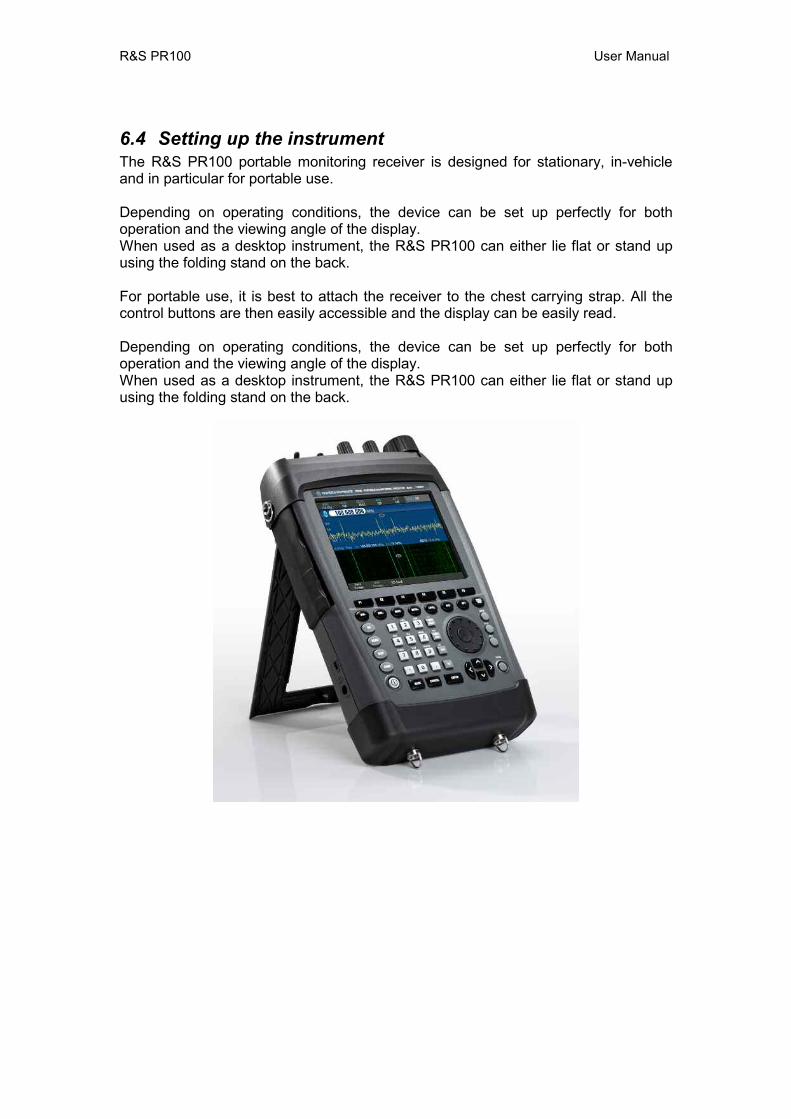
6.4 Setting up the instrument The R&S PR100 portable monitoring receiver is designed for stationary, in-vehicle and in particular for portable use. Depending on operating conditions, the device can be set up perfectly for both operation and the viewing angle of the display. When used as a desktop instrument, the R&S PR100 can either lie flat or stand up using the folding stand on the back. For portable use, it is best to attach the receiver to the chest carrying strap. All the control buttons are then easily accessible and the display can be easily read. Depending on operating conditions, the device can be set up perfectly for both operation and the viewing angle of the display. When used as a desktop instrument, the R&S PR100 can either lie flat or stand up using the folding stand on the back.

R&S PR100 User Manual
6.5 Inserting the battery The R&S PR100 is fitted with a lithium ion battery. The HA-Z206 battery pack has a charging capacity of 6.75 Ah. The battery is inserted into the bottom right of the instrument. The cover must first be pulled downwards to unlock it and then folded upwards to open it. The battery is NOT fitted in the R&S PR100 on delivery and must therefore be fitted before the device can be used for the first time.
6.6 Connecting to the power supply The R&S PR100 can be powered using the mains power adaptor or the internal battery supplied. When fully charged, the built-in lithium ion battery permits approx. 3.5 hours of operation. When the R&S PR100 is delivered, the battery may be completely discharged. Should you wish to use it without a mains power connection you will therefore need to charge it. Charging time is approx. 3.5 hours with the device switched off. During operation using mains power, the R&S PR100 simultaneously charges the internal battery. Insert the power adaptor plug into the POWER ADAPTOR socket on the left-hand side of the device until it clicks into place. Then connect the adaptor to the mains power socket. The adapter voltage range is 100 V to 240 V AC / 50 Hz to 60 Hz. The PR100's DC supply range is +15 V DC +/-10%, max. 2 A

R&S PR100 User Manual
Caution! The R&S HA-Z201 power adaptor supplied should only be used to operate the device or to charge the battery using mains power. Ensure that the mains supply voltage is compatible with the voltage specified on the adaptor before use. Attach the appropriate connector before inserting the adaptor into the AC power outlet.
6.7 Charging the Battery The R&S PR100 is equipped with a lithium ion battery. The battery permits approximately 3.5 hours' operation at room temperature when it is fully charged. Caution! On delivery, the R&S PR100's battery is not fully
charged. The battery therefore needs to be charged before the device can be used for the first time.
If the unit is stored for an extended period, self-discharge will reduce the battery's charge. The battery should therefore be charged before use if it is intended to be the sole power source for an extended period. The charge status of the battery pack is shown on the instrument's display. The battery can either be charged directly in the instrument by using the supplied adaptor or with the optional external R&S HA-Z203 battery charger. Charging takes approx. 7 hours with the device switched on. For faster charging, switch off the instrument during charging. Charging takes approx. 3.5 hours with the device switched off or by using the external charging unit.
R&S PR100 User Manual
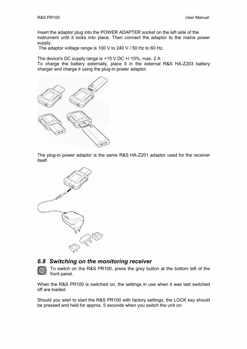
Insert the adaptor plug into the POWER ADAPTER socket on the left side of the instrument until it locks into place. Then connect the adaptor to the mains power supply. The adaptor voltage range is 100 V to 240 V / 50 Hz to 60 Hz. The device's DC supply range is +15 V DC +/-10%, max. 2 A To charge the battery externally, place it in the external R&S HA-Z203 battery charger and charge it using the plug-in power adaptor.
The plug-in power adaptor is the same R&S HA-Z201 adaptor used for the receiver itself.
6.8 Switching on the monitoring receiver To switch on the R&S PR100, press the grey button at the bottom left of the front panel.
When the R&S PR100 is switched on, the settings in use when it was last switched off are loaded. Should you wish to start the R&S PR100 with factory settings, the LOCK key should be pressed and held for approx. 5 seconds when you switch the unit on.
R&S PR100 User Manual
6.9 Ambient and operating conditions The R&S® PR100 will operate reliably in the following ambient and operating conditions: Max. humidity 95 % Rated operating altitude max. 4600 m above sea level Transport altitude max. 12000 m above sea level Excess voltage category 2 Pollution level 2
6.10 Preventive maintenance Any dirt should be removed from the R&S® PR100 with a soft damp cloth and a mild detergent. In case of a fault the following safety-critical parts should only be replaced with original Rohde & Schwarz spare parts: Power adaptor 1309.6100.00 Battery charger 1309.6123.00 Six-cell battery pack 1309.6149.00
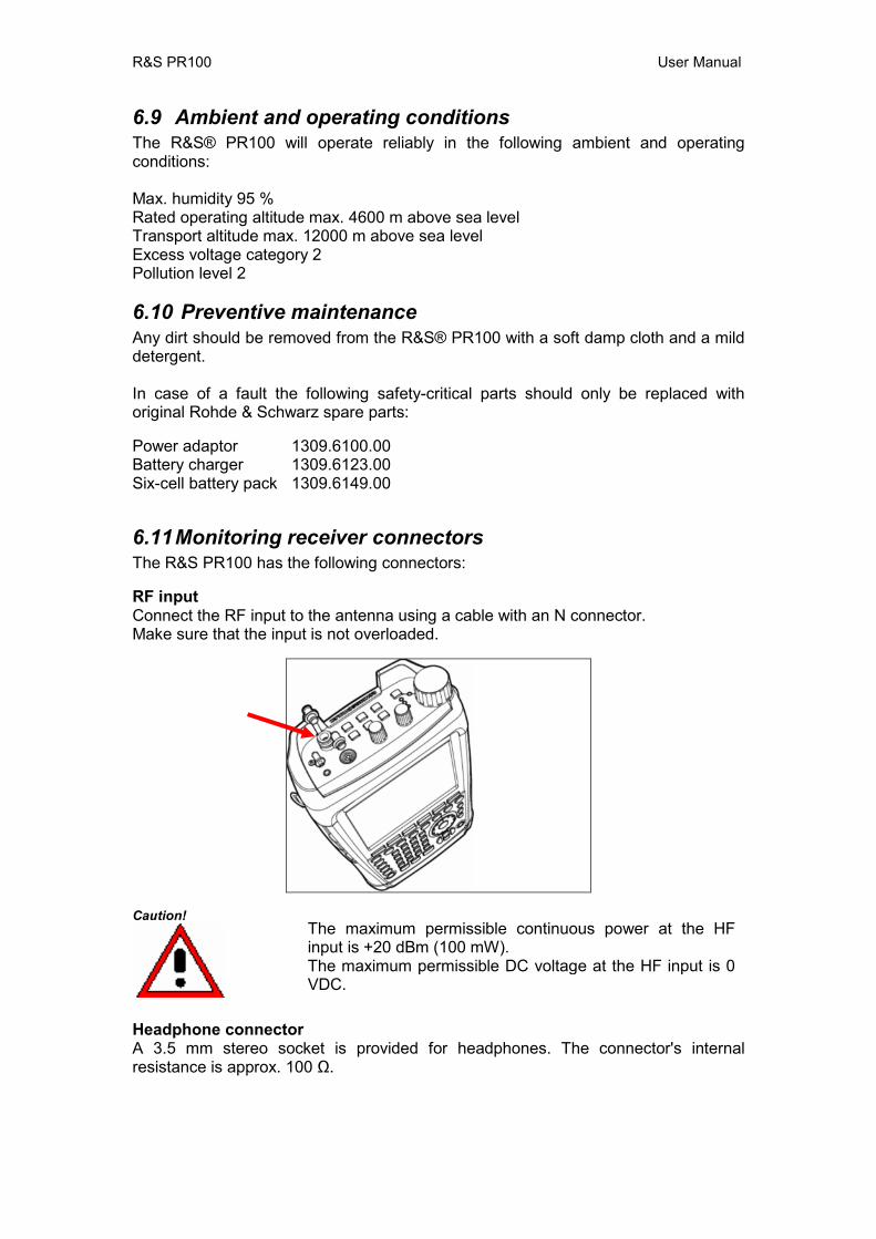
6.11 Monitoring receiver connectors The R&S PR100 has the following connectors: RF input Connect the RF input to the antenna using a cable with an N connector. Make sure that the input is not overloaded.
Caution! The maximum permissible continuous power at the HF input is +20 dBm (100 mW). The maximum permissible DC voltage at the HF input is 0 VDC.
Headphone connector A 3.5 mm stereo socket is provided for headphones. The connector's internal resistance is approx. 100 Ω.
R&S PR100 User Manual
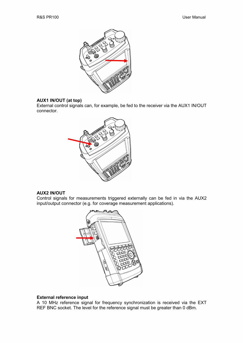
AUX1 IN/OUT (at top) External control signals can, for example, be fed to the receiver via the AUX1 IN/OUT connector.
AUX2 IN/OUT Control signals for measurements triggered externally can be fed in via the AUX2 input/output connector (e.g. for coverage measurement applications).
External reference input A 10 MHz reference signal for frequency synchronization is received via the EXT REF BNC socket. The level for the reference signal must be greater than 0 dBm.
R&S PR100 User Manual
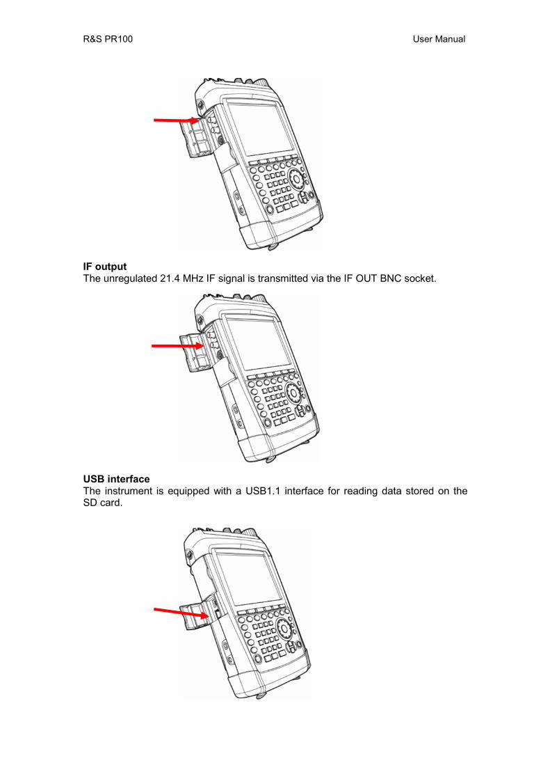
IF output The unregulated 21.4 MHz IF signal is transmitted via the IF OUT BNC socket.
USB interface The instrument is equipped with a USB1.1 interface for reading data stored on the SD card.
R&S PR100 User Manual
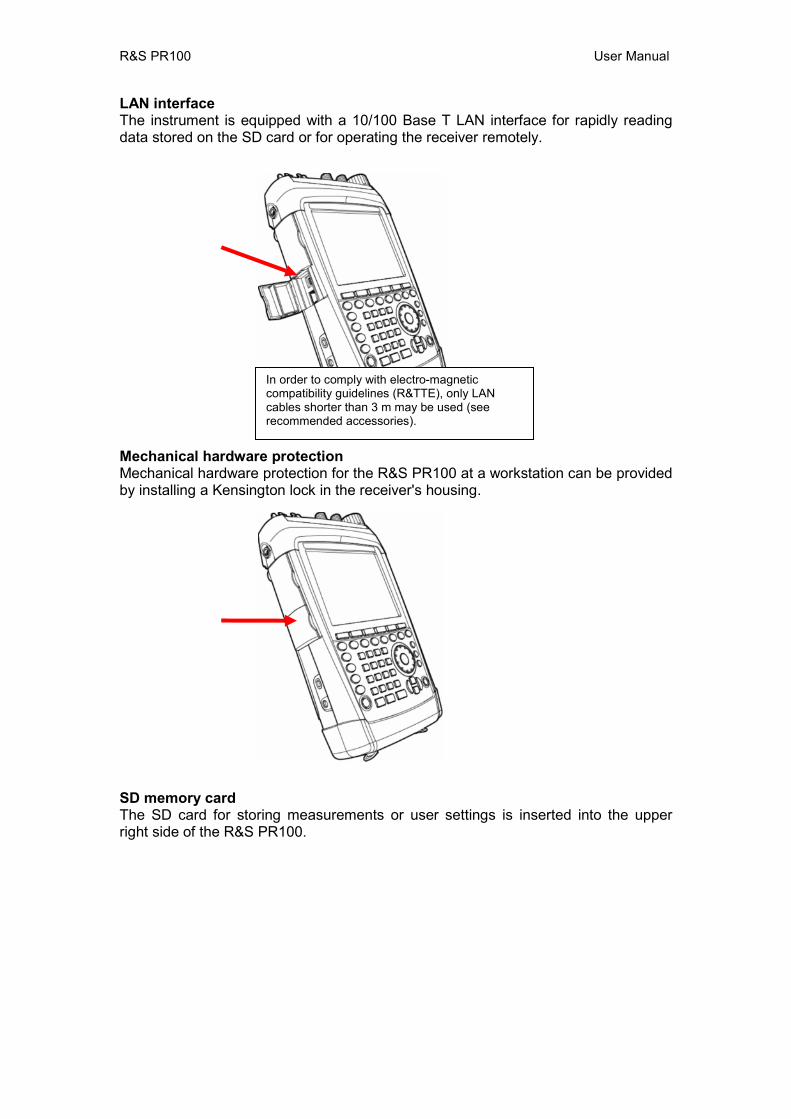
LAN interface The instrument is equipped with a 10/100 Base T LAN interface for rapidly reading data stored on the SD card or for operating the receiver remotely.
Mechanical hardware protection Mechanical hardware protection for the R&S PR100 at a workstation can be provided by installing a Kensington lock in the receiver's housing.
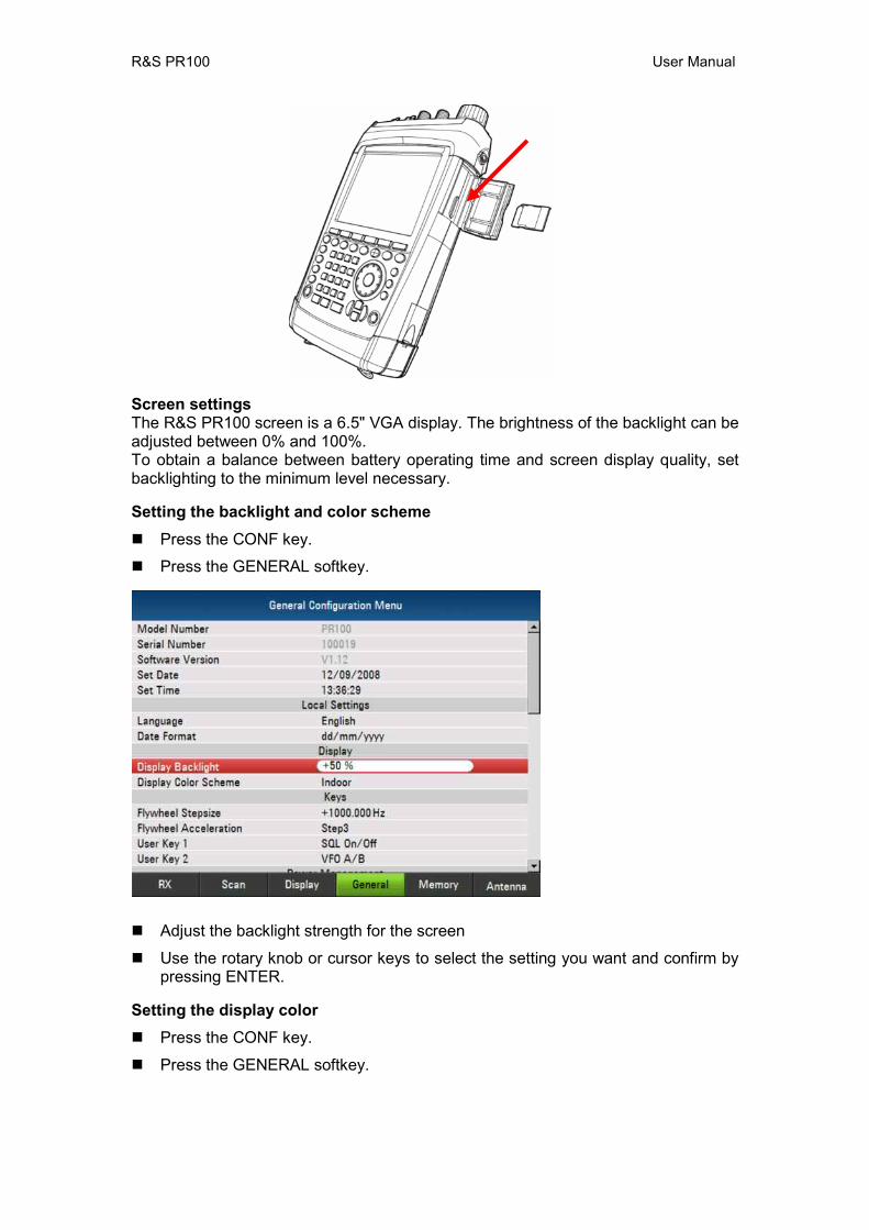
SD memory card The SD card for storing measurements or user settings is inserted into the upper right side of the R&S PR100.
In order to comply with electro-magnetic compatibility guidelines (R&TTE), only LAN cables shorter than 3 m may be used (see recommended accessories).
R&S PR100 User Manual
Screen settings The R&S PR100 screen is a 6.5" VGA display. The brightness of the backlight can be adjusted between 0% and 100%. To obtain a balance between battery operating time and screen display quality, set backlighting to the minimum level necessary. Setting the backlight and color scheme Press the CONF key.
Press the GENERAL softkey.
Adjust the backlight strength for the screen
Use the rotary knob or cursor keys to select the setting you want and confirm by pressing ENTER.
Setting the display color Press the CONF key.
Press the GENERAL softkey.
R&S PR100 User Manual
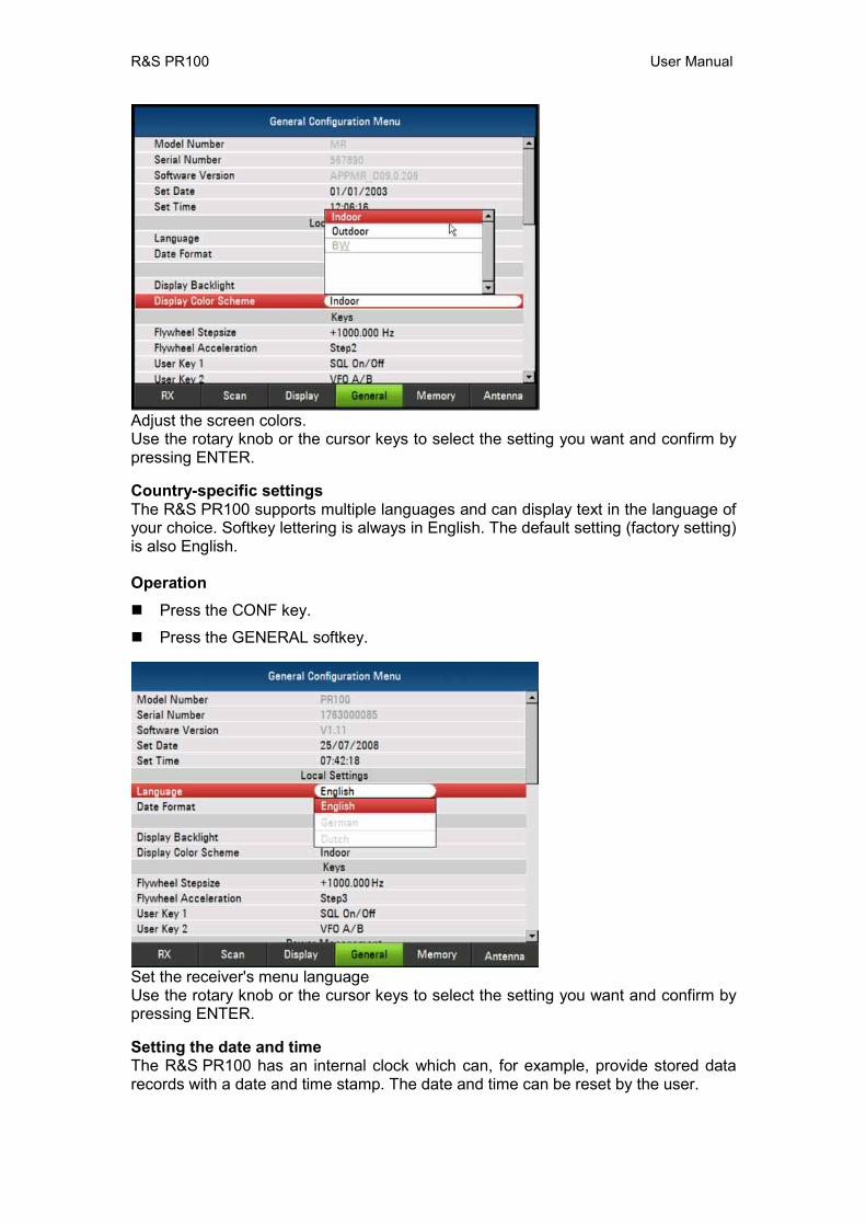
Adjust the screen colors. Use the rotary knob or the cursor keys to select the setting you want and confirm by pressing ENTER. Country-specific settings The R&S PR100 supports multiple languages and can display text in the language of your choice. Softkey lettering is always in English. The default setting (factory setting) is also English. Operation Press the CONF key.
Press the GENERAL softkey.
Set the receiver's menu language Use the rotary knob or the cursor keys to select the setting you want and confirm by pressing ENTER. Setting the date and time The R&S PR100 has an internal clock which can, for example, provide stored data records with a date and time stamp. The date and time can be reset by the user.
R&S PR100 User Manual
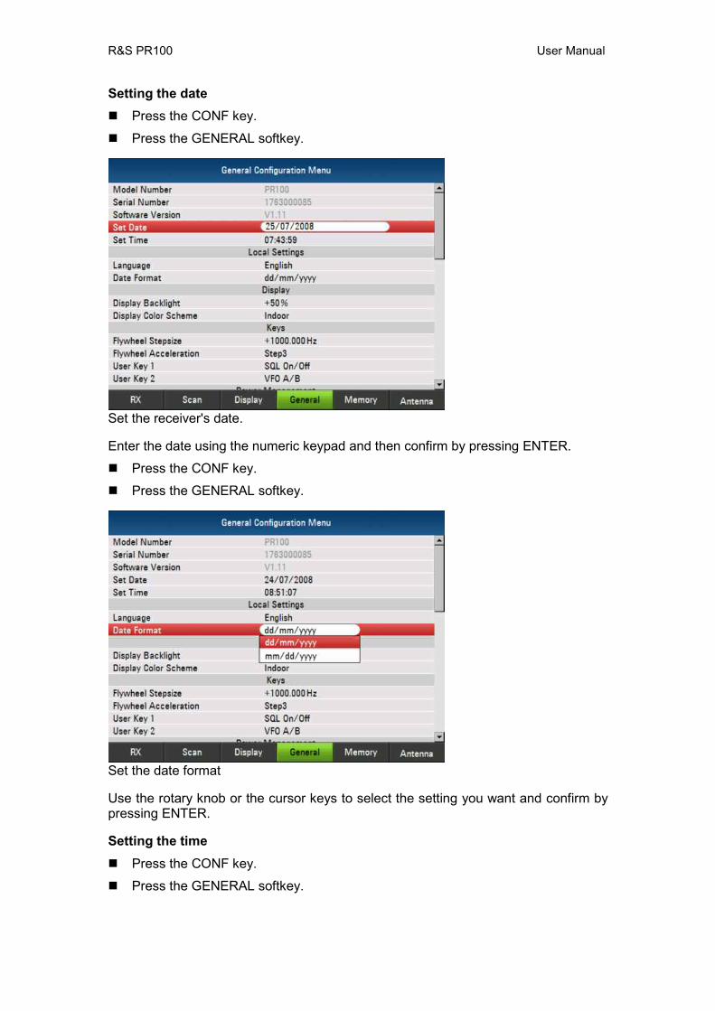
Setting the date Press the CONF key.
Press the GENERAL softkey.
Set the receiver's date. Enter the date using the numeric keypad and then confirm by pressing ENTER.
Press the CONF key.
Press the GENERAL softkey.
Set the date format Use the rotary knob or the cursor keys to select the setting you want and confirm by pressing ENTER. Setting the time Press the CONF key.
Press the GENERAL softkey.
R&S PR100 User Manual
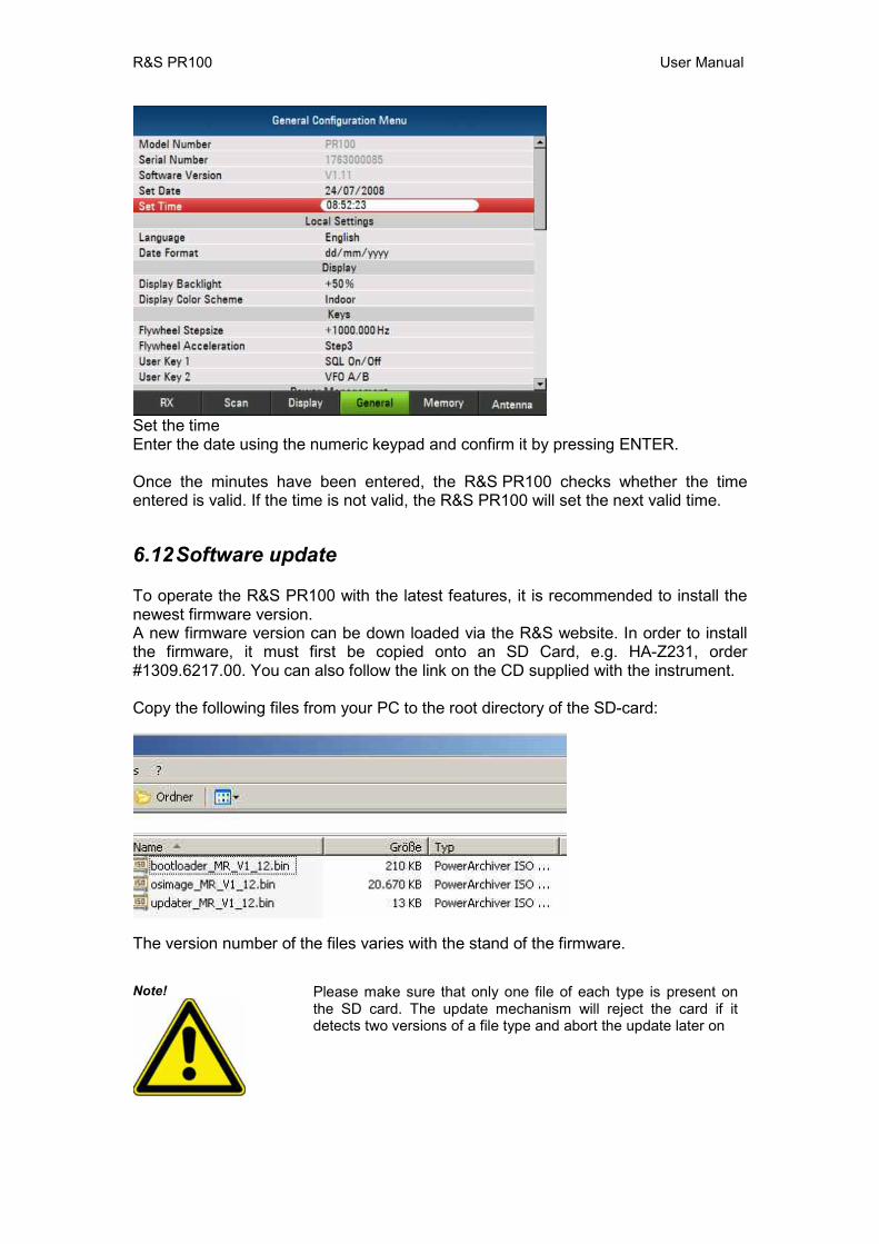
Set the time Enter the date using the numeric keypad and confirm it by pressing ENTER. Once the minutes have been entered, the R&S PR100 checks whether the time entered is valid. If the time is not valid, the R&S PR100 will set the next valid time.
6.12 Software update To operate the R&S PR100 with the latest features, it is recommended to install the newest firmware version. A new firmware version can be down loaded via the R&S website. In order to install the firmware, it must first be copied onto an SD Card, e.g. HA-Z231, order #1309.6217.00. You can also follow the link on the CD supplied with the instrument. Copy the following files from your PC to the root directory of the SD-card:
The version number of the files varies with the stand of the firmware.
Note! Please make sure that only one file of each type is present on the SD card. The update mechanism will reject the card if it detects two versions of a file type and abort the update later on
R&S PR100 User Manual
Switch the instrument of
Insert the SD card into the SD card slot on the right side of the PR100
Connect a mains-adapter (otherwise the PR100 will refuse to start the firmware update)
During pressing the buttons [LOCK] and [8] at the same time, switch on the PR100. Keep both buttons [LOCK] and [8] pressed for about 5 seconds after switching on the PR100.
Continue following the instructions on the PR100’s screen. Caution! Risk of damage to the instrument
DURING FIRMWARE UPGRADE, DO NOT TURN OFF THE PR100!
In order to make the update effective, turn off the PR100 and turn it on again.
During the first start up after updating the firmware, press the buttons [LOCK] and [F6] for about 5 seconds. This will format the PR100’s file system to start from a defined basis after the update.
Formating process takes about 3 minutes.
Your PR100 is now updated successfully.
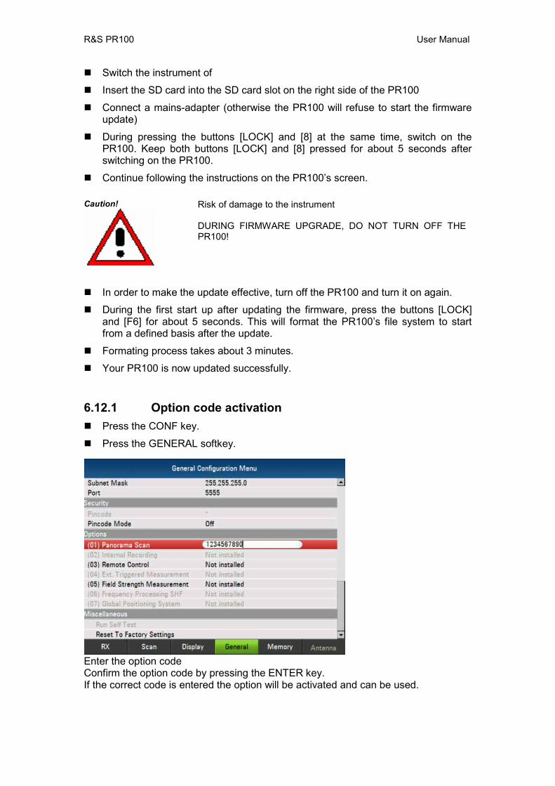
6.12.1 Option code activation Press the CONF key.
Press the GENERAL softkey.
Enter the option code Confirm the option code by pressing the ENTER key. If the correct code is entered the option will be activated and can be used.
R&S PR100 User Manual
7 Configuration Menus
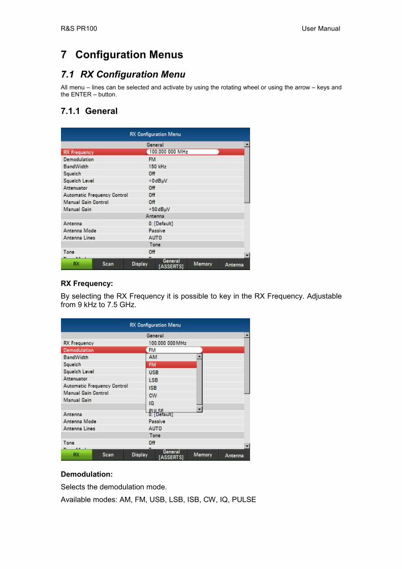
7.1 RX Configuration Menu All menu – lines can be selected and activate by using the rotating wheel or using the arrow – keys and the ENTER – button.
7.1.1 General
RX Frequency: By selecting the RX Frequency it is possible to key in the RX Frequency. Adjustable from 9 kHz to 7.5 GHz.
Demodulation: Selects the demodulation mode.
Available modes: AM, FM, USB, LSB, ISB, CW, IQ, PULSE
R&S PR100 User Manual
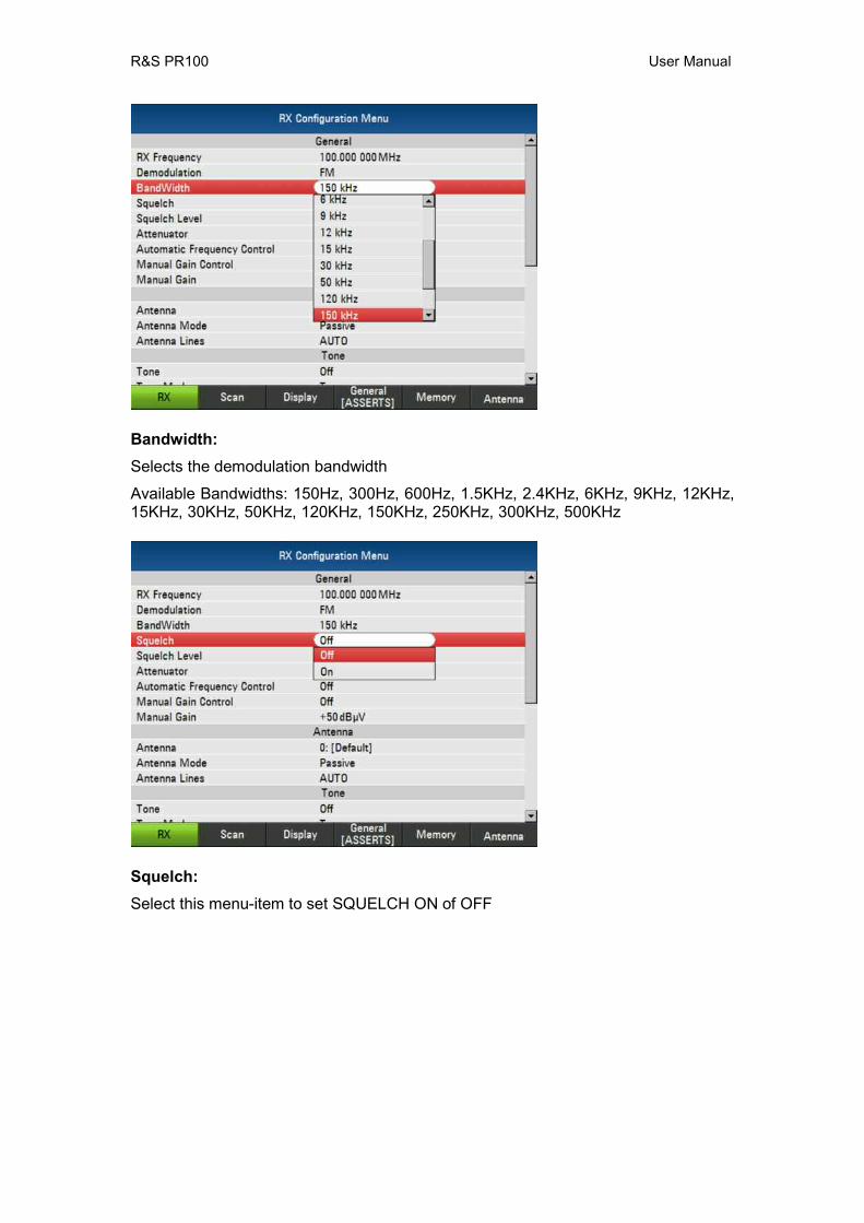
Bandwidth: Selects the demodulation bandwidth
Available Bandwidths: 150Hz, 300Hz, 600Hz, 1.5KHz, 2.4KHz, 6KHz, 9KHz, 12KHz, 15KHz, 30KHz, 50KHz, 120KHz, 150KHz, 250KHz, 300KHz, 500KHz
Squelch: Select this menu-item to set SQUELCH ON of OFF
R&S PR100 User Manual
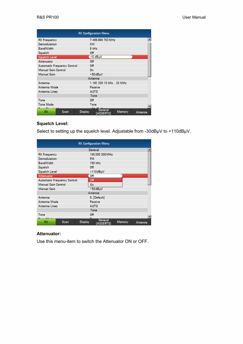
Squelch Level: Select to setting up the squelch level. Adjustable from -30dBµV to +110dBµV.
Attenuator: Use this menu-item to switch the Attenuator ON or OFF.

R&S PR100 User Manual
Automatic Frequency Control: This menu-item allows you to activate or deactivate automatic frequency correction.
Manual Gain Control: Switches the Manual Gain Control ON or OFF
R&S PR100 User Manual
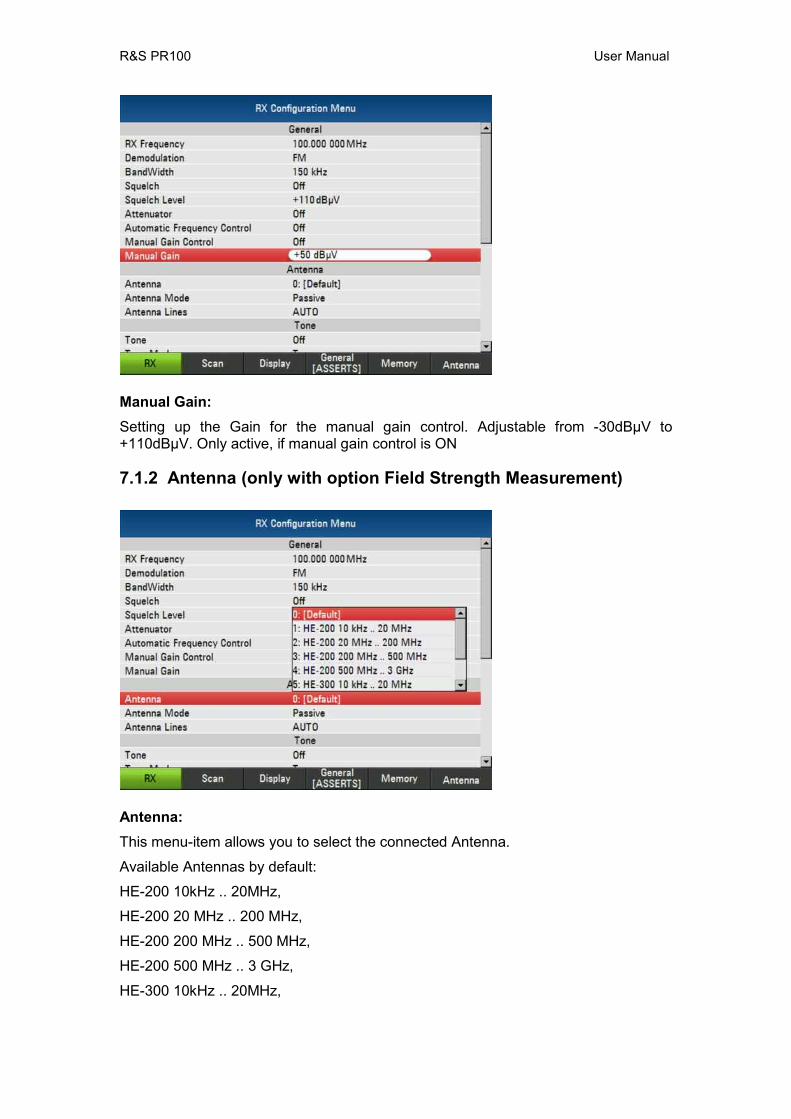
Manual Gain: Setting up the Gain for the manual gain control. Adjustable from -30dBµV to +110dBµV. Only active, if manual gain control is ON
7.1.2 Antenna (only with option Field Strength Measurement)
Antenna: This menu-item allows you to select the connected Antenna.
Available Antennas by default:
HE-200 10kHz .. 20MHz,
HE-200 20 MHz .. 200 MHz,
HE-200 200 MHz .. 500 MHz,
HE-200 500 MHz .. 3 GHz,
HE-300 10kHz .. 20MHz,
R&S PR100 User Manual
HE-300 20 MHz .. 200 MHz,
HE-300 200 MHz .. 500 MHz,
HE-300 500 MHz .. 7 GHz
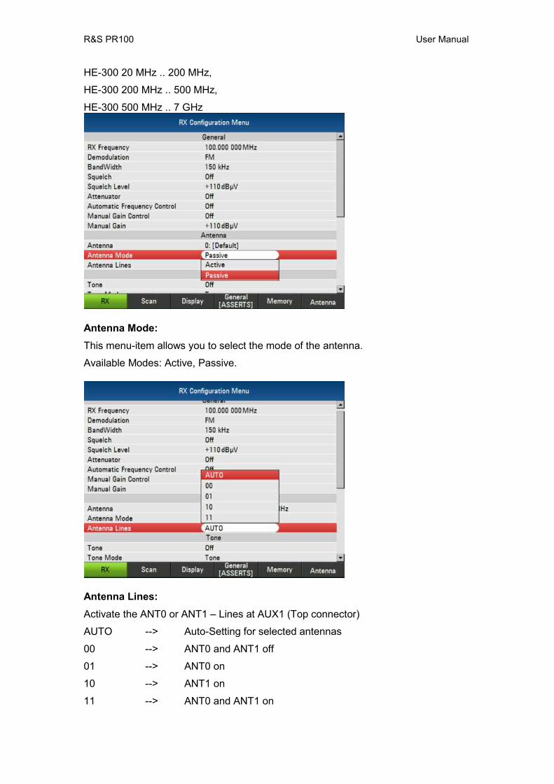
Antenna Mode: This menu-item allows you to select the mode of the antenna.
Available Modes: Active, Passive.
Antenna Lines: Activate the ANT0 or ANT1 – Lines at AUX1 (Top connector)
AUTO --> Auto-Setting for selected antennas
00 --> ANT0 and ANT1 off
01 --> ANT0 on
10 --> ANT1 on
11 --> ANT0 and ANT1 on

R&S PR100 User Manual
7.1.3 Tone
Tone: Select this menu-item to switch the tone ON or OFF the.
Tone Mode: Select this menu-item to select
Available Modes: Tone, AF + Tone
R&S PR100 User Manual
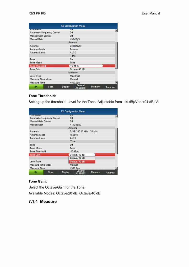
Tone Threshold: Setting up the threshold - level for the Tone. Adjustable from -14 dBµV to +94 dBµV.
Tone Gain: Select the Octave/Gain for the Tone.
Available Modes: Octave/20 dB, Octave/40 dB
7.1.4 Measure
R&S PR100 User Manual
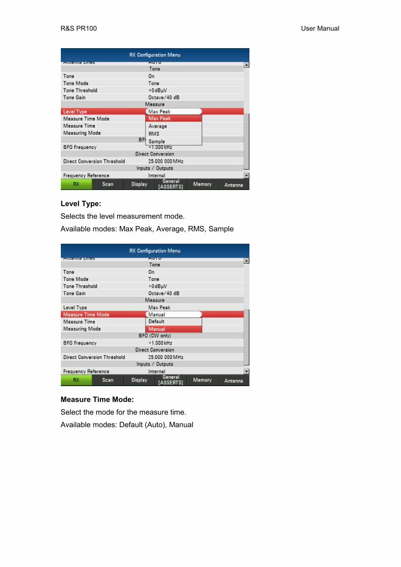
Level Type: Selects the level measurement mode.
Available modes: Max Peak, Average, RMS, Sample
Measure Time Mode: Select the mode for the measure time.
Available modes: Default (Auto), Manual
R&S PR100 User Manual
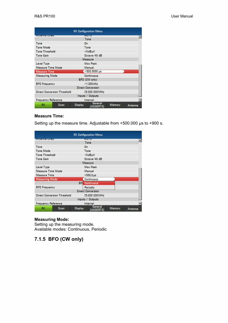
Measure Time: Setting up the measure time. Adjustable from +500.000 µs to +900 s.
Measuring Mode: Setting up the measuring mode. Available modes: Continuous, Periodic
7.1.5 BFO (CW only)

R&S PR100 User Manual
Beat Frequency Oszillator (BFO): Use this field to set the BFO frequency. Please note that this value is irrelevant unless the demodulation mode is CW. Adjustable from -8.000 kHz to +8 kHz.
7.1.6 Direct Conversion Threshold
Direct Conversion Threshold: Setting up the conversion Threshold. Adjustable from 20.000 000 MHz to 30.000 000 MHz.
7.1.7 Inputs / Outputs
R&S PR100 User Manual
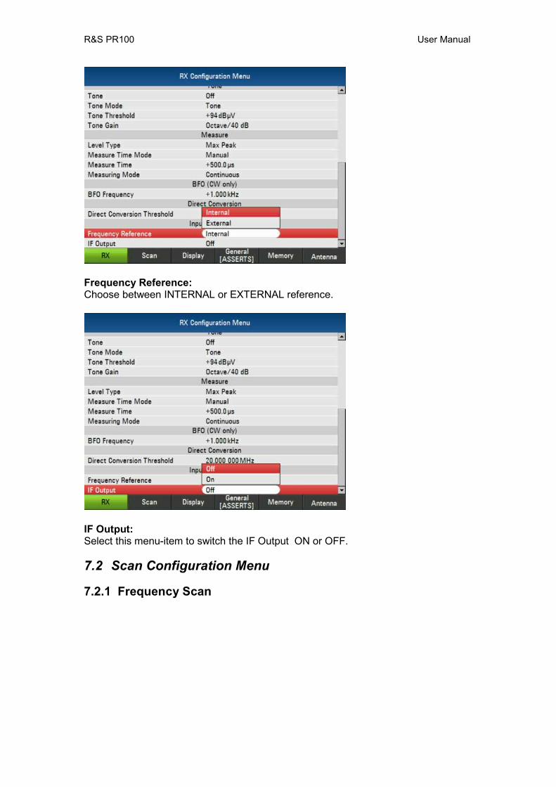
Frequency Reference: Choose between INTERNAL or EXTERNAL reference.
IF Output: Select this menu-item to switch the IF Output ON or OFF.
7.2 Scan Configuration Menu
7.2.1 Frequency Scan

R&S PR100 User Manual
Scan Start Frequency: Setting up the start frequency for the frequency scan.
Scan Stop Frequency: Setting up the stop frequency for the frequency scan.
R&S PR100 User Manual
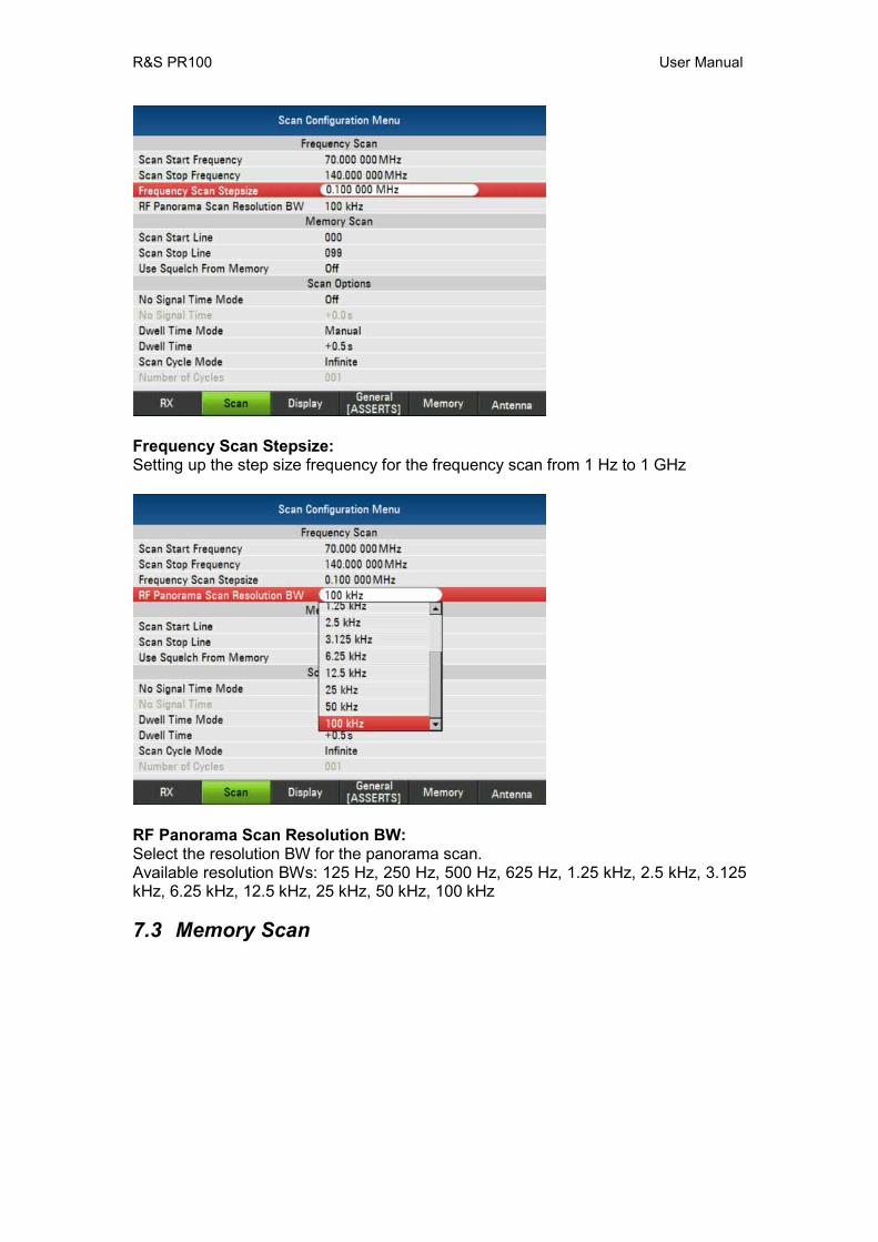
Frequency Scan Stepsize: Setting up the step size frequency for the frequency scan from 1 Hz to 1 GHz
RF Panorama Scan Resolution BW: Select the resolution BW for the panorama scan. Available resolution BWs: 125 Hz, 250 Hz, 500 Hz, 625 Hz, 1.25 kHz, 2.5 kHz, 3.125 kHz, 6.25 kHz, 12.5 kHz, 25 kHz, 50 kHz, 100 kHz
7.3 Memory Scan

R&S PR100 User Manual
Scan Start Line: Select the start line for the memory scan. Max. lines: 1024
Scan Stop Line: Select the stop line for the memory scan. Max. lines: 1024

R&S PR100 User Manual
Use Squelch From Memory: Select this menu-item to switch using squelch from memory ON or OFF.
7.3.1 Scan Options
No Signal Time Mode: Choose between OFF or VARIABLE for the no signal time mode.
R&S PR100 User Manual
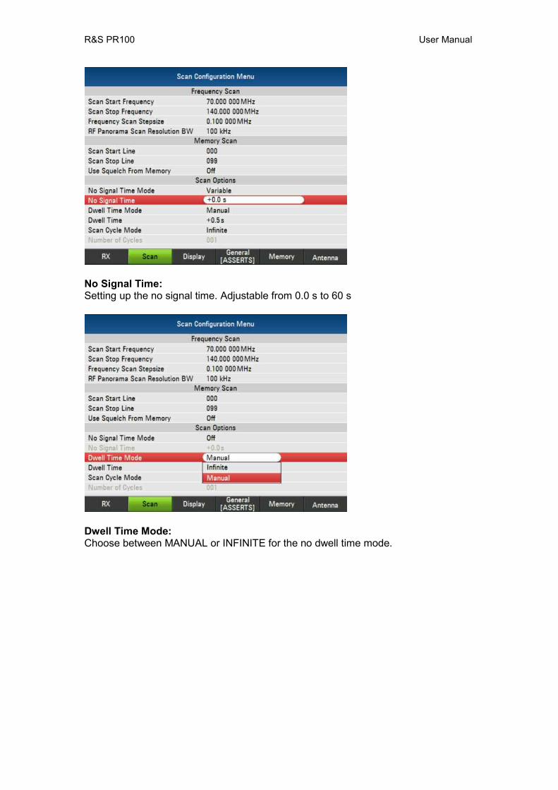
No Signal Time: Setting up the no signal time. Adjustable from 0.0 s to 60 s
Dwell Time Mode: Choose between MANUAL or INFINITE for the no dwell time mode.
R&S PR100 User Manual
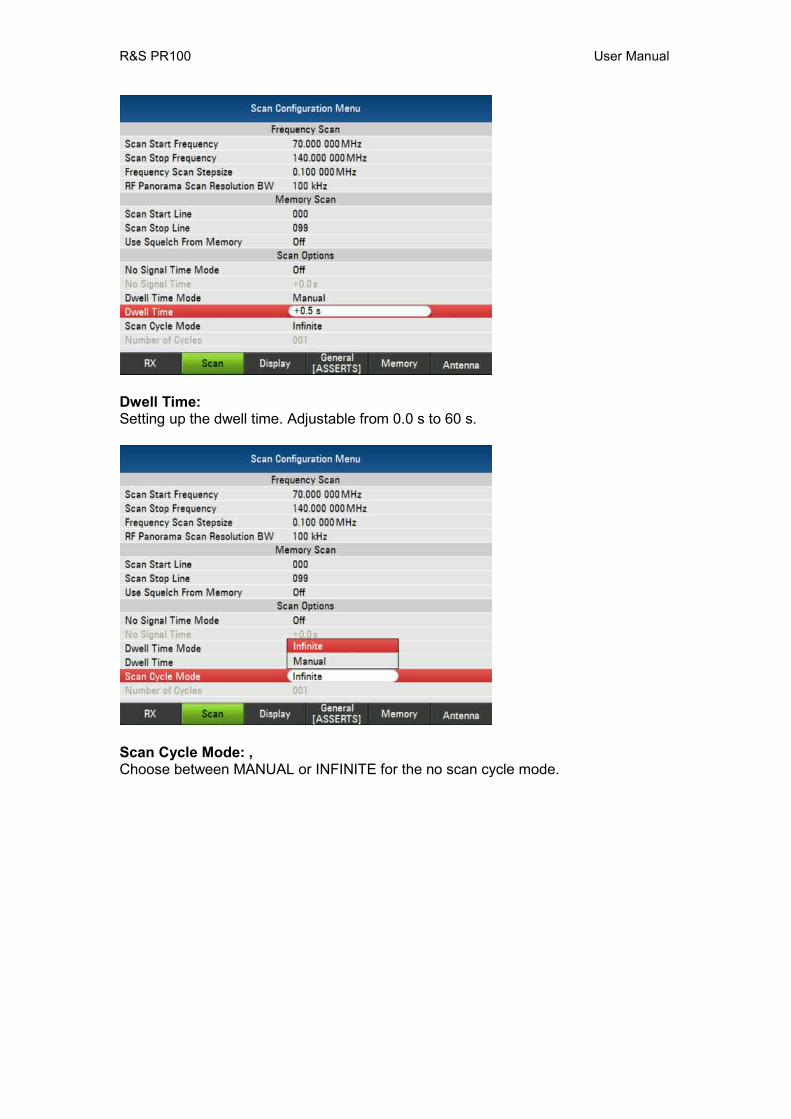
Dwell Time: Setting up the dwell time. Adjustable from 0.0 s to 60 s.
Scan Cycle Mode: , Choose between MANUAL or INFINITE for the no scan cycle mode.

R&S PR100 User Manual
Number of Cycles: Enter the number of cycles for the scans. Only selectable if scan cycle mode is Manual. Max. Number of Cycles: 1000
7.4 Display
7.4.1 RX Screen
Level Bar Low Limit: Setting up the low limit for the level bar. Adjustable from -30 dBµV to +110 dBµV
R&S PR100 User Manual
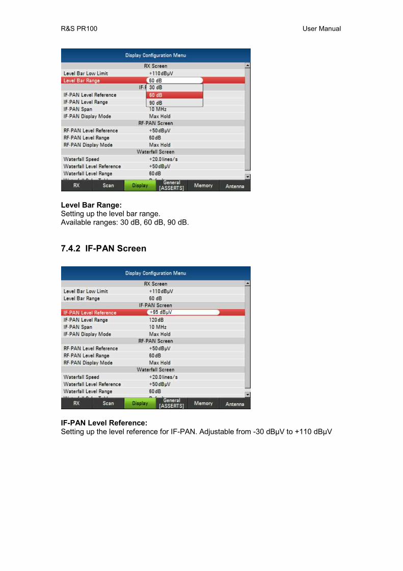
Level Bar Range: Setting up the level bar range. Available ranges: 30 dB, 60 dB, 90 dB.
7.4.2 IF-PAN Screen
IF-PAN Level Reference: Setting up the level reference for IF-PAN. Adjustable from -30 dBµV to +110 dBµV
R&S PR100 User Manual
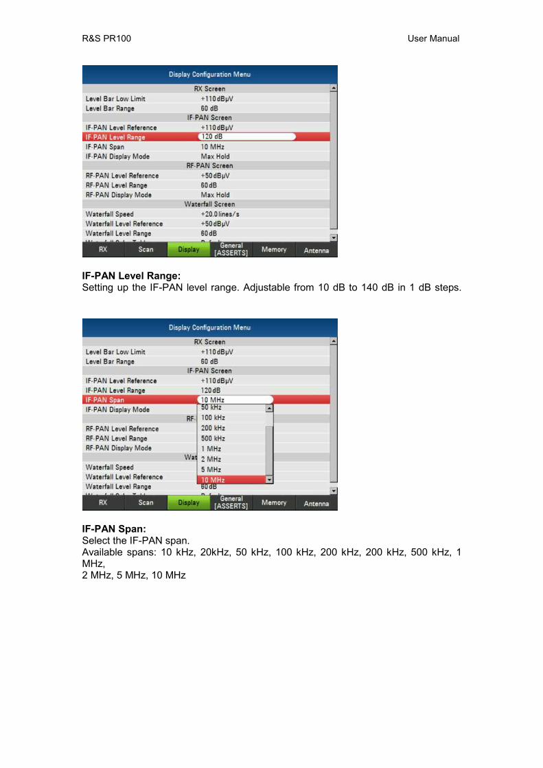
IF-PAN Level Range: Setting up the IF-PAN level range. Adjustable from 10 dB to 140 dB in 1 dB steps.
IF-PAN Span: Select the IF-PAN span. Available spans: 10 kHz, 20kHz, 50 kHz, 100 kHz, 200 kHz, 200 kHz, 500 kHz, 1 MHz, 2 MHz, 5 MHz, 10 MHz

R&S PR100 User Manual
IF-PAN Display Mode: Select the display mode. Available modes: Normal, Max Hold, Avg, Min Hold
7.4.3 RF-PAN Screen
RF-PAN Level Reference: Setting up the level reference for RF-PAN. Adjustable from -30 dBµV to +110 dBµV.

R&S PR100 User Manual
RF-PAN Level Range: Setting up the RF-PAN level range. Adjustable from 10 dB to 140 dB in 1 dB steps.
RF-PAN Display Mode: Select the display mode. Available modes: Normal, Max Hold, Avg, Min Hold
7.4.4 Waterfall Screen
R&S PR100 User Manual
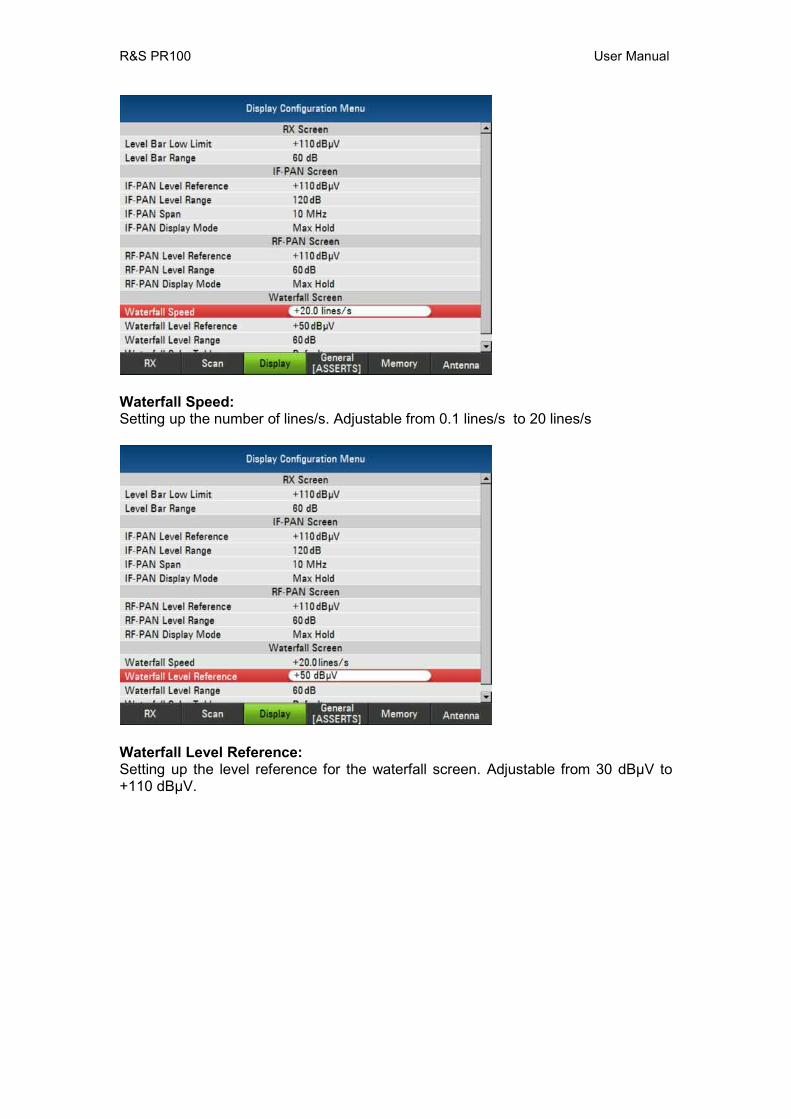
Waterfall Speed: Setting up the number of lines/s. Adjustable from 0.1 lines/s to 20 lines/s
Waterfall Level Reference: Setting up the level reference for the waterfall screen. Adjustable from 30 dBµV to +110 dBµV.
R&S PR100 User Manual
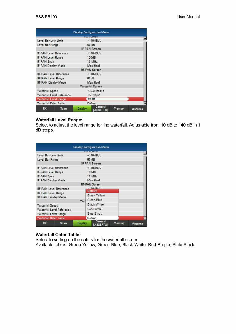
Waterfall Level Range: Select to adjust the level range for the waterfall. Adjustable from 10 dB to 140 dB in 1 dB steps.
Waterfall Color Table: Select to setting up the colors for the waterfall screen. Available tables: Green-Yellow, Green-Blue, Black-White, Red-Purple, Blule-Black

R&S PR100 User Manual
7.5 General Configuration Menu
7.5.1 General
Set Date: Setting up the date.
Set Time: Setting up the time.
R&S PR100 User Manual
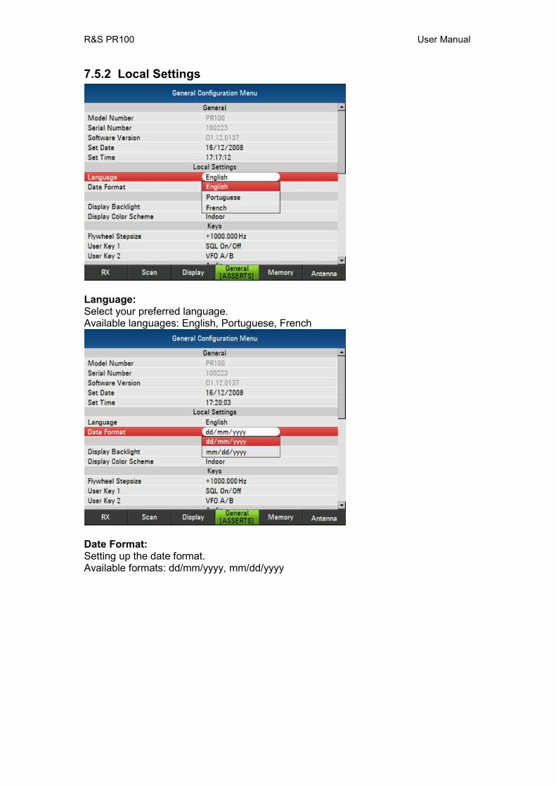
7.5.2 Local Settings
Language: Select your preferred language. Available languages: English, Portuguese, French
Date Format: Setting up the date format. Available formats: dd/mm/yyyy, mm/dd/yyyy
R&S PR100 User Manual
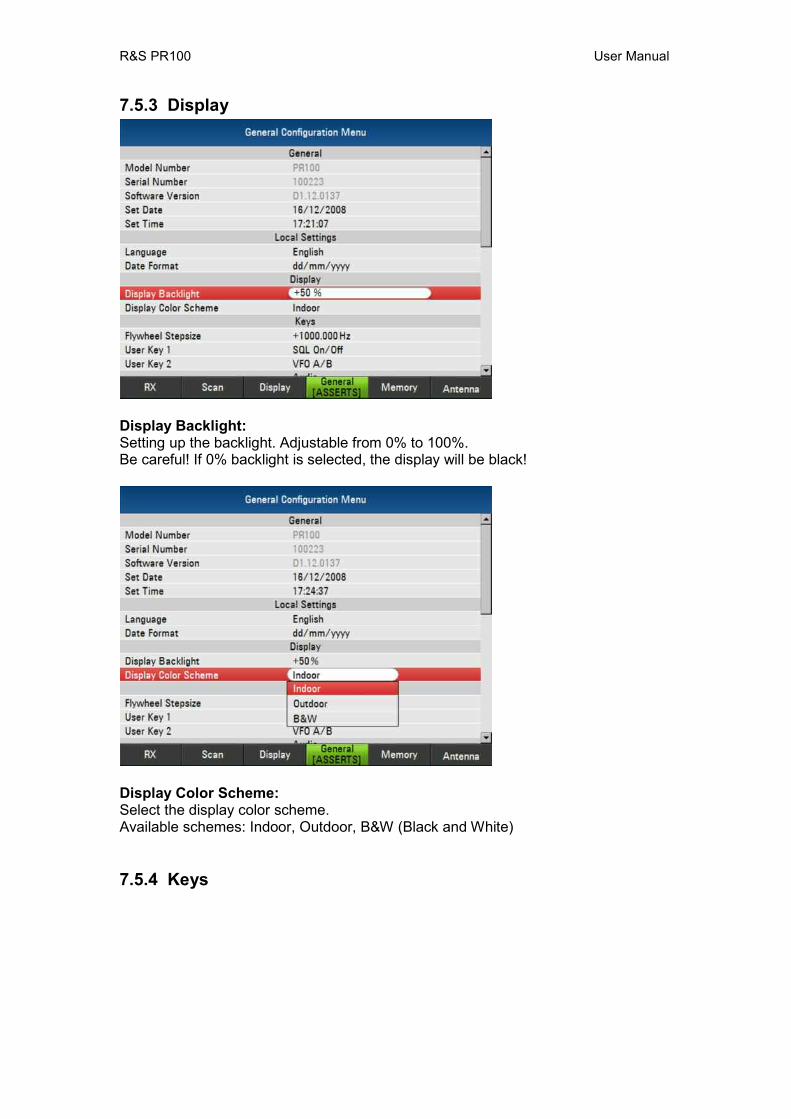
7.5.3 Display
Display Backlight: Setting up the backlight. Adjustable from 0% to 100%. Be careful! If 0% backlight is selected, the display will be black!
Display Color Scheme: Select the display color scheme. Available schemes: Indoor, Outdoor, B&W (Black and White)
7.5.4 Keys
R&S PR100 User Manual
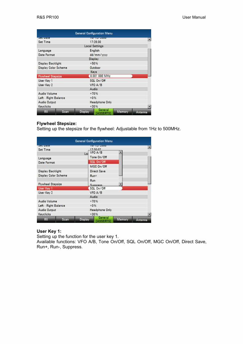
Flywheel Stepsize: Setting up the stepsize for the flywheel: Adjustable from 1Hz to 500MHz.
User Key 1: Setting up the function for the user key 1. Available functions: VFO A/B, Tone On/Off, SQL On/Off, MGC On/Off, Direct Save, Run+, Run-, Suppress.
R&S PR100 User Manual
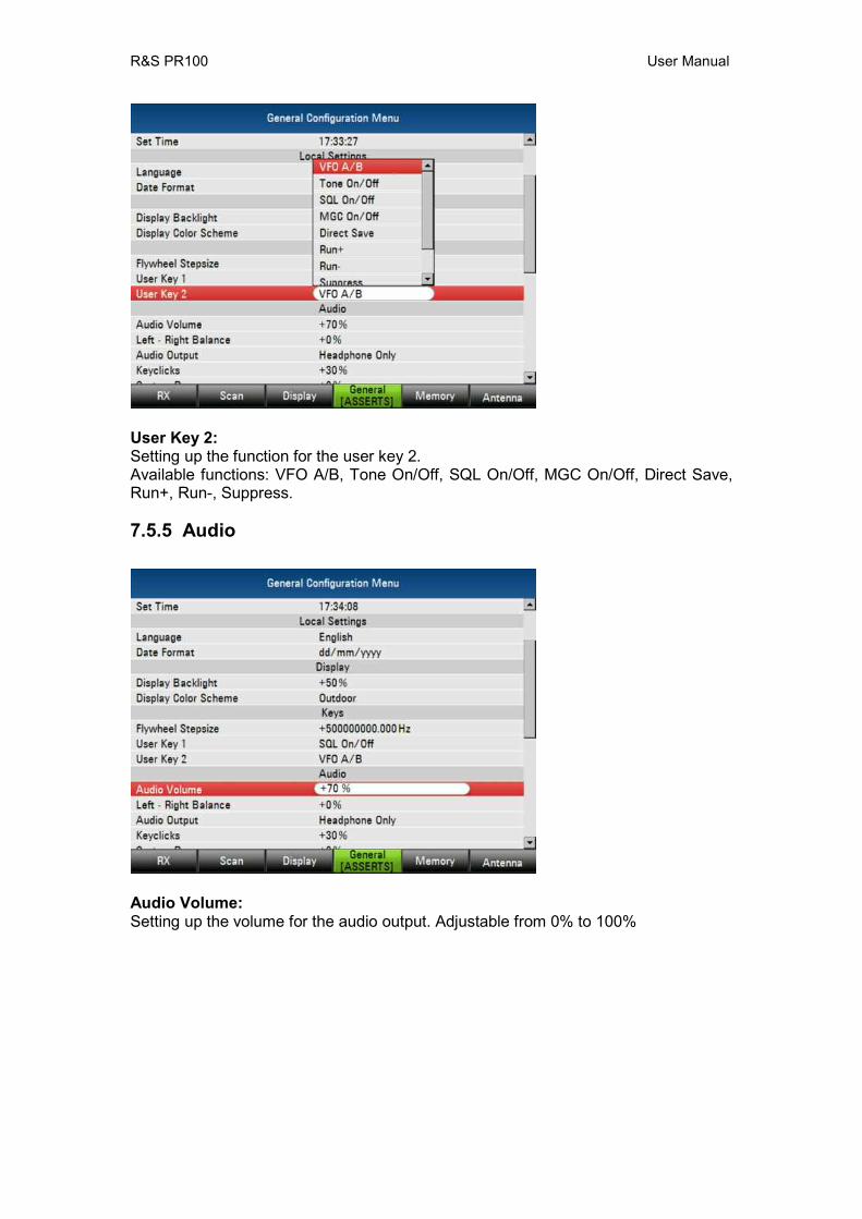
User Key 2: Setting up the function for the user key 2. Available functions: VFO A/B, Tone On/Off, SQL On/Off, MGC On/Off, Direct Save, Run+, Run-, Suppress.
7.5.5 Audio
Audio Volume: Setting up the volume for the audio output. Adjustable from 0% to 100%
R&S PR100 User Manual
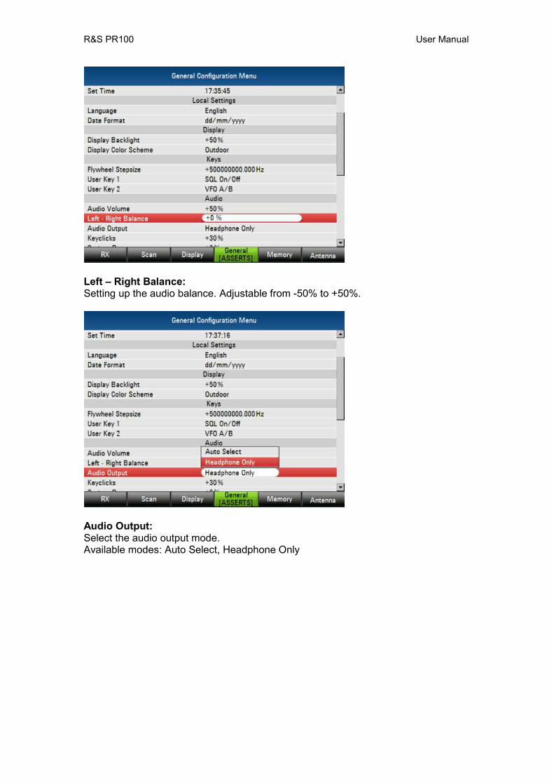
Left – Right Balance: Setting up the audio balance. Adjustable from -50% to +50%.
Audio Output: Select the audio output mode. Available modes: Auto Select, Headphone Only
R&S PR100 User Manual
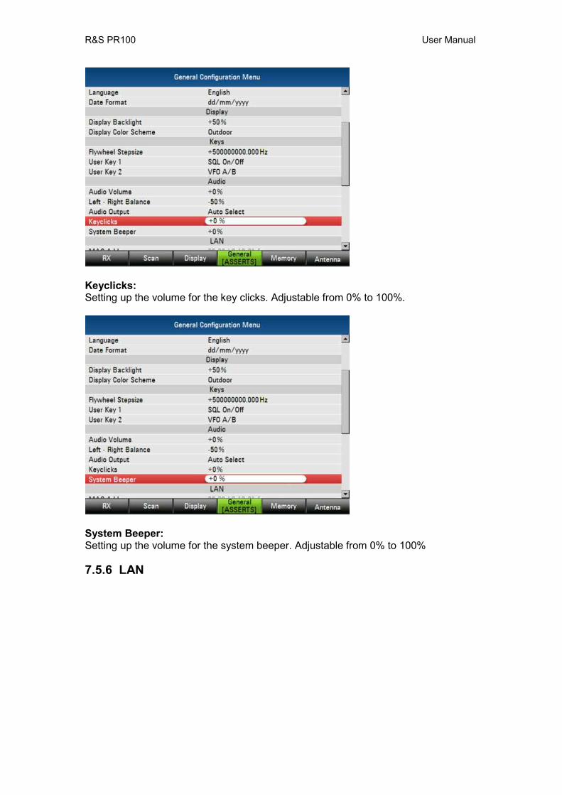
Keyclicks: Setting up the volume for the key clicks. Adjustable from 0% to 100%.
System Beeper: Setting up the volume for the system beeper. Adjustable from 0% to 100%
7.5.6 LAN
R&S PR100 User Manual
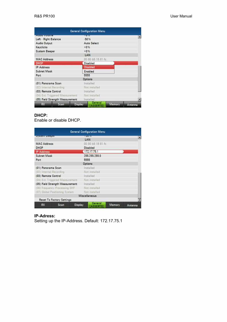
DHCP: Enable or disable DHCP.
IP-Adress: Setting up the IP-Address. Default: 172.17.75.1
R&S PR100 User Manual
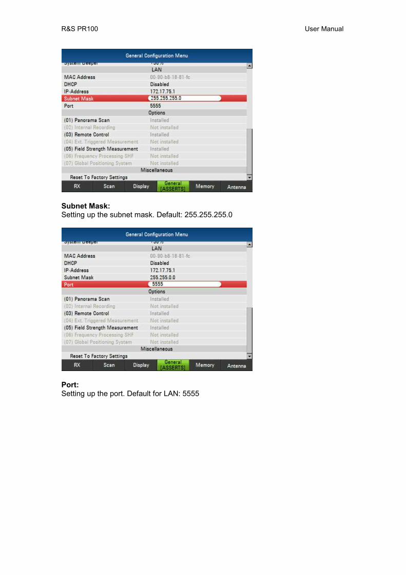
Subnet Mask: Setting up the subnet mask. Default: 255.255.255.0
Port: Setting up the port. Default for LAN: 5555
R&S PR100 User Manual
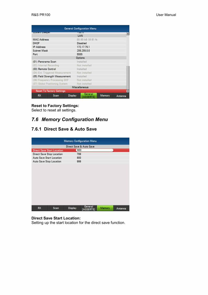
Reset to Factory Settings: Select to reset all settings.
7.6 Memory Configuration Menu
7.6.1 Direct Save & Auto Save
Direct Save Start Location: Setting up the start location for the direct save function.
R&S PR100 User Manual
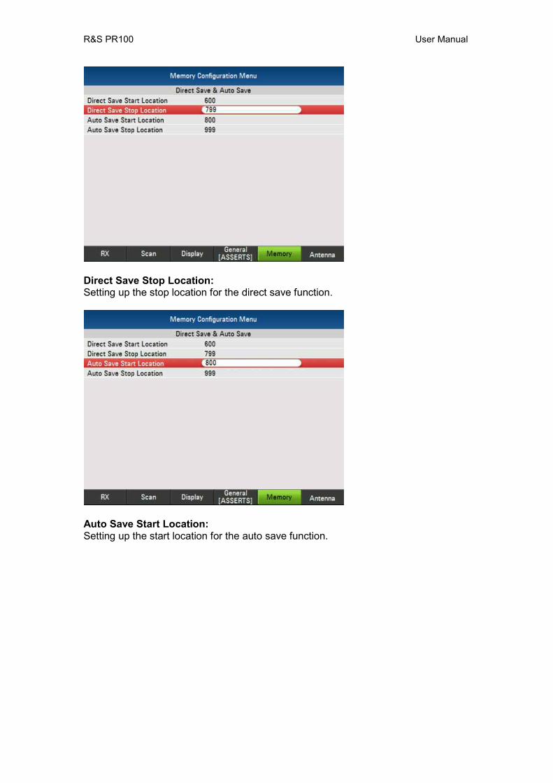
Direct Save Stop Location: Setting up the stop location for the direct save function.
Auto Save Start Location: Setting up the start location for the auto save function.
R&S PR100 User Manual
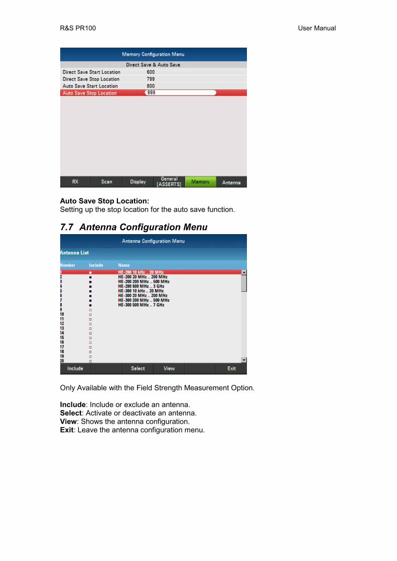
Auto Save Stop Location: Setting up the stop location for the auto save function.
7.7 Antenna Configuration Menu
Only Available with the Field Strength Measurement Option. Include: Include or exclude an antenna. Select: Activate or deactivate an antenna. View: Shows the antenna configuration. Exit: Leave the antenna configuration menu.
R&S PR100 User Manual
8 SCPI Interface
8.1 Document Outline The SCPI standard describes an interface with which instruments can be controlled. The idea behind SCPI is that it should not matter what kind of instrument measures e.g. a voltage level, be it a multimeter or a radio scanner measuring the voltage at the antenna output; the command should always be the same. Although theoretically possible, in practice this goal in unachievable. However, the goal of every instrument designer is to stay as close to SCPI as possible. The goal of every instrument designer is to stay as close to SCPI as possible. In addition, the PR100 tries to be backward compatible with its predecessor, the EB200 Miniport Receiver, when possible. In fact, this compatibility requirement outweighs the SCPI compliance requirement. Therefore, the SCPI interface for the PR100 is defined with the following rules:
1. If an EB200 SCPI command relates to functionality that is not supported by the PR100, the command is not supported either.
2. If a function can be done via an existing EB200 SCPI command, that command is supported.
3. If a function cannot be done via an existing EB200 SCPI command, but a suitable SCPI compliant command is available, the SCPI compliant command is supported.
4. Otherwise, a new SCPI-like command is added, specific for the PR100 Each command is described in detail in Chapter 11. A command is rarely useful if no data can be retrieved to monitor its effect. In SCPI, this is done via queries. Queries can be used to retrieve the settings of an instrument. However, measurements can consist of large sets of data. Outputting that over the SCPI interface could delay the reaction time to commands, which is why the PR100 also offers the data in another format that can be sent via the UDP/IP protocol (internet).
8.2 Legend
Abbreviations Used
Abbreviation Meaning
R&S PR100 User Manual
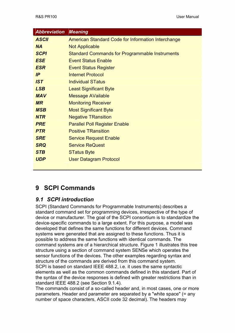
Abbreviation Meaning ASCII American Standard Code for Information Interchange NA Not Applicable SCPI Standard Commands for Programmable Instruments ESE Event Status Enable ESR Event Status Register IP Internet Protocol IST Individual STatus LSB Least Significant Byte MAV Message AVailable MR Monitoring Receiver MSB Most Significant Byte NTR Negative TRansition PRE Parallel Poll Register Enable PTR Positive TRansition SRE Service Request Enable SRQ Service ReQuest STB STatus Byte UDP User Datagram Protocol
9 SCPI Commands
9.1 SCPI introduction SCPI (Standard Commands for Programmable Instruments) describes a standard command set for programming devices, irrespective of the type of device or manufacturer. The goal of the SCPI consortium is to standardize the device-specific commands to a large extent. For this purpose, a model was developed that defines the same functions for different devices. Command systems were generated that are assigned to these functions. Thus it is possible to address the same functions with identical commands. The command systems are of a hierarchical structure. Figure 1 illustrates this tree structure using a section of command system SENSe which operates the sensor functions of the devices. The other examples regarding syntax and structure of the commands are derived from this command system. SCPI is based on standard IEEE 488.2, i.e. it uses the same syntactic elements as well as the common commands defined in this standard. Part of the syntax of the device responses is defined with greater restrictions than in standard IEEE 488.2 (see Section 9.1.4). The commands consist of a so-called header and, in most cases, one or more parameters. Header and parameter are separated by a "white space" (= any number of space characters, ASCII code 32 decimal). The headers may

R&S PR100 User Manual
consist of several keywords. Queries are formed by directly appending a question mark to the header.
9.1.1 Common Command Structure Common commands consist of a header preceded by an asterisk "*" and one or several parameters, if any. Examples: *RST RESET, resets the device *ESE 253 EVENT STATUS ENABLE, sets the bits of the event status enable register to 253 *ESR? EVENT STATUS QUERY, queries the contents of the event status register.
9.1.2 Device-Specific Command Structure Hierarchy Device-specific commands are of hierarchical structure (see Figure 1). Commands of the highest level (root level) consist of only one keyword. This keyword denotes a complete command system. Example: SYSTem This keyword denotes the command system SYSTem. For commands of lower levels, the complete path has to be specified, starting on the left with the highest level, the individual keywords being separated by a colon ":". Example: SENSe:FREQuency:STARt 118 MHz
This command lies in the third level of the SENSe system. It sets the starting frequency of a scan to 118 MHz.
Figure 1: Tree-Structure example of SENSe system Keywords that occur at several levels within one command system can have different effects. Example: MMEMory:CATalog?
List all files in the current directory.
SYSTe
DATE COMMunicate
GPIB LAN SOCKet
DHCP
PORT
AUDio
R&S PR100 User Manual
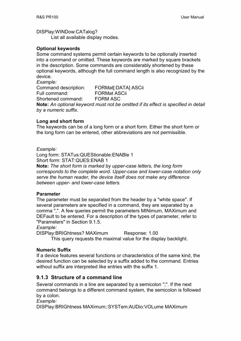
DISPlay:WINDow:CATalog? List all available display modes. Optional keywords Some command systems permit certain keywords to be optionally inserted into a command or omitted. These keywords are marked by square brackets in the description. Some commands are considerably shortened by these optional keywords, although the full command length is also recognized by the device. Example: Command description: FORMat[:DATA] ASCii Full command: FORMat ASCii Shortened command: FORM ASC Note: An optional keyword must not be omitted if its effect is specified in detail by a numeric suffix.
Long and short form The keywords can be of a long form or a short form. Either the short form or the long form can be entered, other abbreviations are not permissible.
Example: Long form: STATus:QUEStionable:ENABle 1 Short form: STAT:QUES:ENAB 1 Note: The short form is marked by upper-case letters, the long form corresponds to the complete word. Upper-case and lower-case notation only serve the human reader, the device itself does not make any difference between upper- and lower-case letters.
Parameter The parameter must be separated from the header by a "white space". If several parameters are specified in a command, they are separated by a comma ",". A few queries permit the parameters MINimum, MAXimum and DEFault to be entered. For a description of the types of parameter, refer to "Parameters" in Section 9.1.5. Example: DISPlay:BRIGhtness? MAXimum Response: 1.00
This query requests the maximal value for the display backlight. Numeric Suffix If a device features several functions or characteristics of the same kind, the desired function can be selected by a suffix added to the command. Entries without suffix are interpreted like entries with the suffix 1.
9.1.3 Structure of a command line Several commands in a line are separated by a semicolon ";". If the next command belongs to a different command system, the semicolon is followed by a colon. Example: DISPlay:BRIGhtness MAXimum;:SYSTem:AUDio:VOLume MAXimum
R&S PR100 User Manual
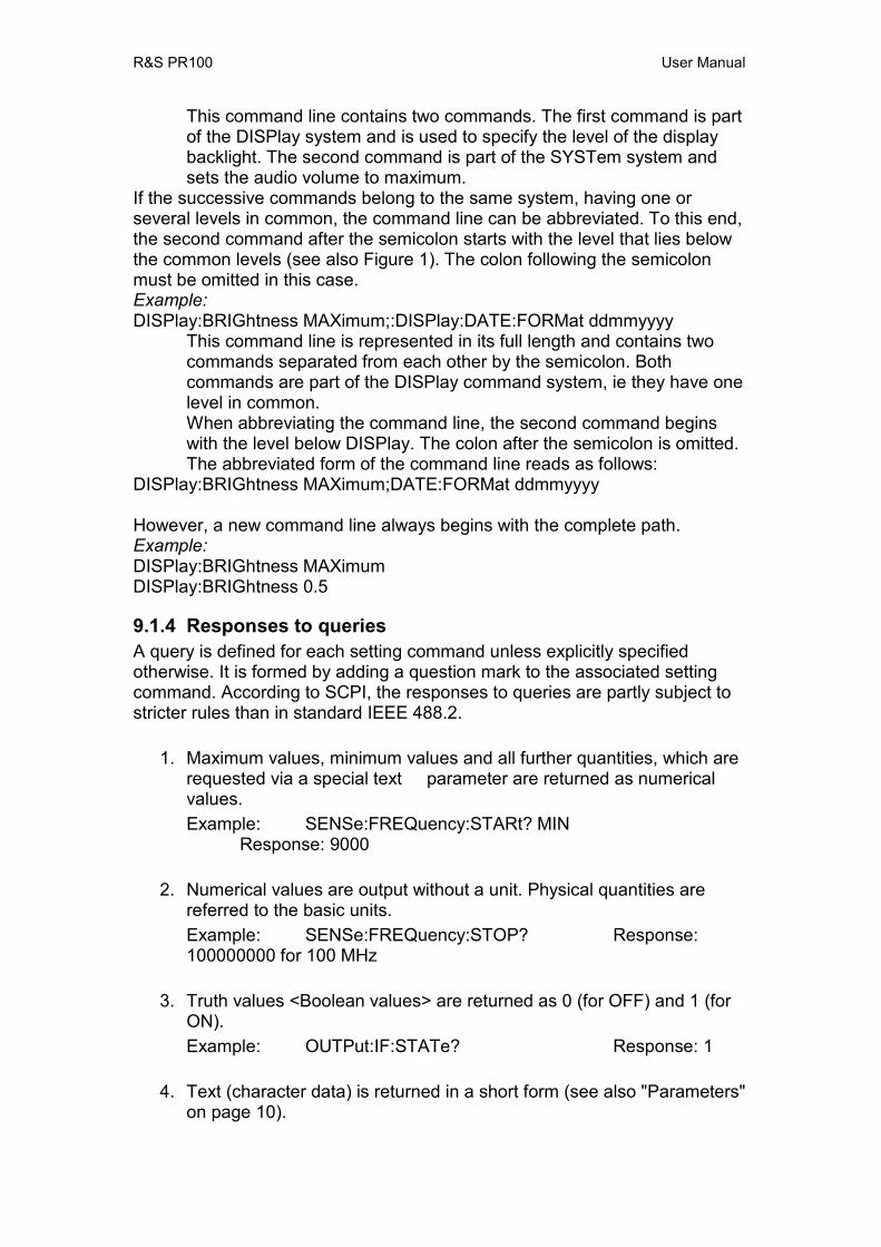
This command line contains two commands. The first command is part of the DISPlay system and is used to specify the level of the display backlight. The second command is part of the SYSTem system and sets the audio volume to maximum.
If the successive commands belong to the same system, having one or several levels in common, the command line can be abbreviated. To this end, the second command after the semicolon starts with the level that lies below the common levels (see also Figure 1). The colon following the semicolon must be omitted in this case. Example: DISPlay:BRIGhtness MAXimum;:DISPlay:DATE:FORMat ddmmyyyy
This command line is represented in its full length and contains two commands separated from each other by the semicolon. Both commands are part of the DISPlay command system, ie they have one level in common. When abbreviating the command line, the second command begins with the level below DISPlay. The colon after the semicolon is omitted. The abbreviated form of the command line reads as follows:
DISPlay:BRIGhtness MAXimum;DATE:FORMat ddmmyyyy However, a new command line always begins with the complete path. Example: DISPlay:BRIGhtness MAXimum DISPlay:BRIGhtness 0.5
9.1.4 Responses to queries A query is defined for each setting command unless explicitly specified otherwise. It is formed by adding a question mark to the associated setting command. According to SCPI, the responses to queries are partly subject to stricter rules than in standard IEEE 488.2.
1. Maximum values, minimum values and all further quantities, which are requested via a special text parameter are returned as numerical values. Example: SENSe:FREQuency:STARt? MIN Response: 9000
2. Numerical values are output without a unit. Physical quantities are referred to the basic units. Example: SENSe:FREQuency:STOP? Response: 100000000 for 100 MHz
3. Truth values <Boolean values> are returned as 0 (for OFF) and 1 (for ON). Example: OUTPut:IF:STATe? Response: 1
4. Text (character data) is returned in a short form (see also "Parameters" on page 10).
R&S PR100 User Manual
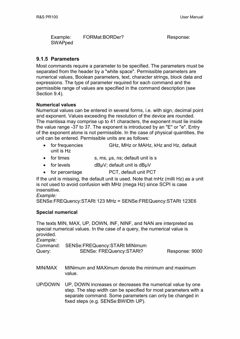
Example: FORMat:BORDer? Response: SWAPped
9.1.5 Parameters Most commands require a parameter to be specified. The parameters must be separated from the header by a "white space". Permissible parameters are numerical values, Boolean parameters, text, character strings, block data and expressions. The type of parameter required for each command and the permissible range of values are specified in the command description (see Section 9.4). Numerical values Numerical values can be entered in several forms, i.e. with sign, decimal point and exponent. Values exceeding the resolution of the device are rounded. The mantissa may comprise up to 41 characters, the exponent must lie inside the value range -37 to 37. The exponent is introduced by an "E" or "e". Entry of the exponent alone is not permissible. In the case of physical quantities, the unit can be entered. Permissible units are as follows:
• for frequencies GHz, MHz or MAHz, kHz and Hz, default unit is Hz
• for times s, ms, µs, ns; default unit is s • for levels dBµV; default unit is dBµV• for percentage PCT, default unit PCT
If the unit is missing, the default unit is used. Note that mHz (milli Hz) as a unit is not used to avoid confusion with MHz (mega Hz) since SCPI is case insensitive. Example: SENSe:FREQuency:STARt 123 MHz = SENSe:FREQuency:STARt 123E6 Special numerical The texts MIN, MAX, UP, DOWN, INF, NINF, and NAN are interpreted as special numerical values. In the case of a query, the numerical value is provided. Example: Command: SENSe:FREQuency:STARt MINimum Query: SENSe: FREQuency:STARt? Response: 9000
MIN/MAX MINimum and MAXimum denote the minimum and maximum value.
UP/DOWN UP, DOWN increases or decreases the numerical value by one
step. The step width can be specified for most parameters with a separate command. Some parameters can only be changed in fixed steps (e.g. SENSe:BWIDth UP).
R&S PR100 User Manual
INF INFinity stands for +∞. For queries the numerical value 9,9E37 is output.
NINF Negative INFinity (NINF) stands for -∞. For queries the
numerical value -9,9E37 is output. In a measured-value query, this value is output if the measurement cannot be carried out (e.g. due to a wrong device setting).
NAN Not A Number (NAN) stands for results of calculations that are
not number. Possible causes are the division by zero, the subtraction of infinity from infinity and simply missing values.. SCPI outputs the value 9,91E37 where NAN is meant. NAN is only sent as a device response, it cannot be entered in a command.
Boolean parameters Boolean parameters represent two states. The ON state (logically true) is represented by ON or a numerical value unequal to 0. The OFF state (logically untrue) is represented by OFF or the numerical value 0. 0 or 1 is provided in a query. Example: Setting command: SYST:COMM:SOCK:DHCP:STAT ON Query: SYST:COMM:SOCK:DHCP:STAT? Response: 1 Text Text parameters (character data) observe the syntactic rules for keywords, i.e. they can be entered using the short or long form. Like any parameter, they have to be separated from the header by a "white space". In the case of a query, the short form of the text is provided.
Example: Setting command: FORMat:BORDer SWAPped Query: FORMat:BORDer? Response SWAP Strings Strings must always be entered in quotation marks (' or "). Example: PROGram:PRESet:DEFine “User Preset 1” PROGram:PRESet:DEFine ‘User Preset 2’
Block Data Block data (Definite Length Block) are a transmission format which is suitable for the transmission of large amounts of data. A command using a block data parameter has the following structure: Example: HEADer:HEADer #45168xxxxxxxx

R&S PR100 User Manual
ASCII character # introduces the data block. The next number indicates how many of the following digits describe the length of the data block. In the example the 4 following digits indicate the length to be 5168 bytes. The data bytes follow; a single character for each byte. Data elements comprising more than one byte are transmitted with the byte being the first that was specified by SCPI command "FORMat:BORDer". During the transmission of the data bytes all flow-control (e.g End-of-Line) that is sent as an ASCII character is ignored until all bytes are transmitted. Note that e.g. a VXI-11 connection also has flow-control that is not sent as ASCII characters. Expressions Expressions must always be in parentheses.
Syntax Elements Table 1 offers an overview of the syntax elements. Table 1: Syntax Elements
Element Comment : The colon separates the key words of a command. In a command
line the colon after the separating semicolon marks the uppermost command level.
; The semicolon separates two commands of a command line. It does not alter the path.
, The comma separates several parameters of a command. ? The question mark forms a query. * The asterisk marks a common command. “ Quotation marks introduce a string and terminate it. # ASCII character # introduces block data. A "white space" (ASCII-Code 0 to 9, 11 to 32 decimal, e g blank)
separates header and parameter. () Parentheses enclose an expression (channel lists).
9.2 Status Reporting The status reporting system stores all the information on the present operating state of a device and on errors that have occurred. This information is stored in the status registers and in the error queue. For each remote client of a device there is a separate status reporting system that offers access to all registers of the error queue. The registers form a hierarchical structure. The register “status byte” (STB) defined in IEEE 488.2 and its associated mask register “service request enable” (SRE) form the uppermost level.
R&S PR100 User Manual
The STB receives information from the other registers and evaluates whether an SRQ or IST message has to be generated: The IST flag ("Individual STatus") and the “parallel poll enable” register (PRE) allocated to it are also part of the status reporting system. The IST flag, like the SRQ, combines the entire device status in a single bit. The PRE fulfils a function for the IST flag as the SRE does for the service request. For SCPI over TCP/IP, an SRQ is a text-response “&SRQ<CR><LF>”, where <CR> is a carriage-return, and <LF> is a line-feed. A C-type string would read as: “&SRQ\r\n”. The message queue contains the messages the device sends back to the controller. It is not part of the status reporting system but determines the value of the “message available” (MAV) bit in STB and is thus shown in Section 9.2.2.2.
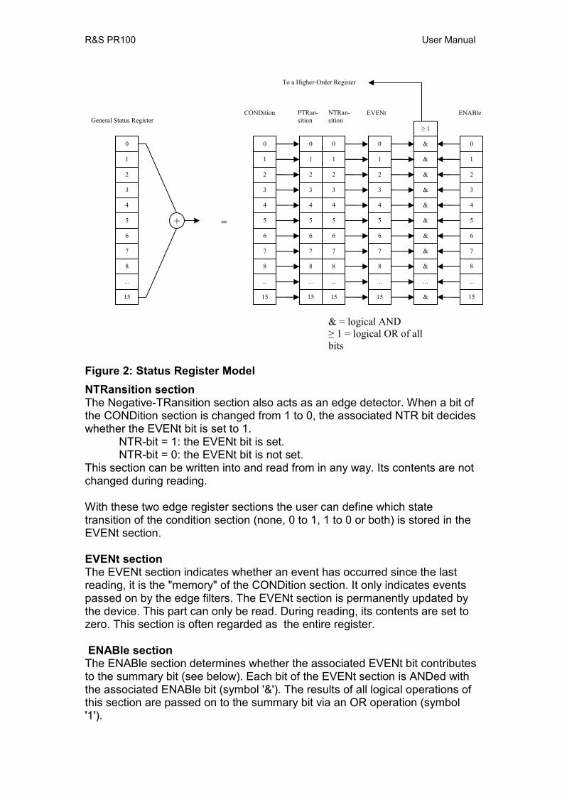
Structure of an SCPI status register
Each SCPI register consists of 5 sections each having a width of 16 bits (see Figure 2). Bit 15 (the most significant bit) is set to zero for all sections. Thus the contents of the register sections can be processed by the controller as positive integers. The function of each section is explained below. CONDition section The CONDition section of a register reflects directly the state of the hardware. This register section can only be read. Its contents are not changed during reading. As an alternative, a bit in a CONDition register can also contain the summary information of a further status register connected in front. In this case, the bit is cleared only when reading out the root-cause of the bit: another bit in another status register connected in front. PTRansition section The Positive-TRansition section acts as an edge detector. When a bit of the CONDition section is changed from 0 to 1, the associated PTR bit decides whether the EVENt bit is set to 1.
PTR bit = 1: the EVENt bit is set. PTR bit = 0: the EVENt bit is not set.
This section can be written into and read from in any way. Its contents are not changed during reading.
R&S PR100 User Manual
Figure 2: Status Register Model NTRansition section The Negative-TRansition section also acts as an edge detector. When a bit of the CONDition section is changed from 1 to 0, the associated NTR bit decides whether the EVENt bit is set to 1.
NTR-bit = 1: the EVENt bit is set. NTR-bit = 0: the EVENt bit is not set.
This section can be written into and read from in any way. Its contents are not changed during reading. With these two edge register sections the user can define which state transition of the condition section (none, 0 to 1, 1 to 0 or both) is stored in the EVENt section. EVENt section The EVENt section indicates whether an event has occurred since the last reading, it is the "memory" of the CONDition section. It only indicates events passed on by the edge filters. The EVENt section is permanently updated by the device. This part can only be read. During reading, its contents are set to zero. This section is often regarded as the entire register. ENABle section
The ENABle section determines whether the associated EVENt bit contributes to the summary bit (see below). Each bit of the EVENt section is ANDed with the associated ENABle bit (symbol '&'). The results of all logical operations of this section are passed on to the summary bit via an OR operation (symbol '1').
+
0
1
2
3
4
5
6
7
8
...
15
0
1
2
3
4
5
6
7
8
...
15
0
1
2
3
4
5
6
7
8
...
15
0
1
2
3
4
5
6
7
8
...
15
0
1
2
3
4
5
6
7
8
...
15
&
&
&
&
&
&
&
&
&
...
&
≥ 1
0
1
2
3
4
5
6
7
8
...
15
=
General Status Register CONDition PTRan-
sition NTRan-sition
EVENt ENABle
To a Higher-Order Register
& = logical AND ≥ 1 = logical OR of all bits
R&S PR100 User Manual
ENABle bit = 0: the associated EVENt bit does not contribute to the summary bit
ENABle bit = 1: if the associated EVENT bit is "1", the summary bit is set to "1" as well. This section can be written into and read by the user in any way. Its contents is not changed during reading. Summary bit As indicated above, the summary bit is obtained from the EVENt and ENABle section for each register. The result is then entered into a bit of the CONDition section of the higher-order register. The device automatically generates the summary bit for each register. Thus an event, e.g. a PLL that has not locked, can lead to a service request through all the hierarchy levels. Note The service request enable register SRE defined in IEEE 488.2 can be taken as ENABle section of the STB if the STB is structured according to SCPI. By analogy, the ESE can be taken as the ENABle section of the ESR.
R&S PR100 User Manual
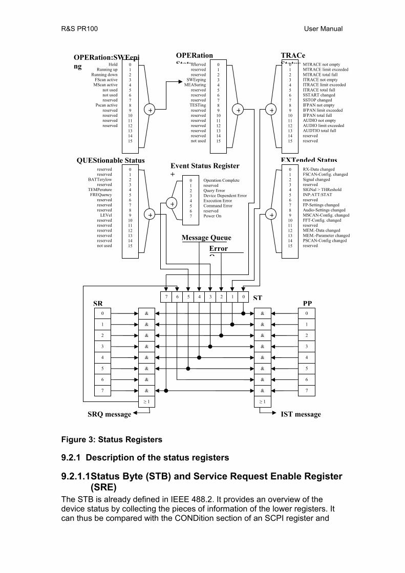
Figure 3: Status Registers
9.2.1 Description of the status registers
9.2.1.1 Status Byte (STB) and Service Request Enable Register (SRE)
The STB is already defined in IEEE 488.2. It provides an overview of the device status by collecting the pieces of information of the lower registers. It can thus be compared with the CONDition section of an SCPI register and
0
1
2
3
4
5
6
7
&
&
&
&
&
&
&
&
0
1
2
3
4
5
6
7
7 6 5 4 3 2 1 0
&
&
&
&
&
&
&
&
≥ 1 ≥ 1
SR PPST
SRQ message IST message
0123456789101112131415
MTRACE not empty MTRACE limit exceeded MTRACE total full ITRACE not empty ITRACE limit exceeded ITRACE total full SSTART changed SSTOP changed IFPAN not empty IFPAN limit exceeded IFPAN total full AUDIO not empty AUDIO limit exceeded AUDTIO total full reserved reserved
TRACe Status
0123456789101112131415
EXTended StatusRX-Data changed FSCAN-Config. changed Signal changed reserved SIGNal > THReshold INP:ATT:STAT reserved FP-Settings changed Audio-Settings changed MSCAN-Config. changed FFT-Config. changed reserved MEM.-Data changed MEM.-Parameter changed PSCAN-Config changed reserved
0123456789101112131415
reservedreservedreserved
SWEepingMEASuring
reservedreservedreserved
TESTingreservedreservedreservedreservedreservedreservednot used
OPERation Status
0123456789101112131415
reservedreserved
BATTerylowreserved
TEMPeratureFREQuency
reservedreservedreserved
LEVelreservedreservedreservedreservedreservednot used
QUEStionable Status
01234567
Operation Complete reserved Query Error Device Dependent Error Execution Error Command Error reserved Power On
Event Status Register +
0123456789101112131415
HoldRunning up
Running downFScan active
MScan activenot usednot usedreserved
Pscan activereservedreservedreservedreserved
OPERation:SWEeping
+
+ + +
++
Message QueueError Q
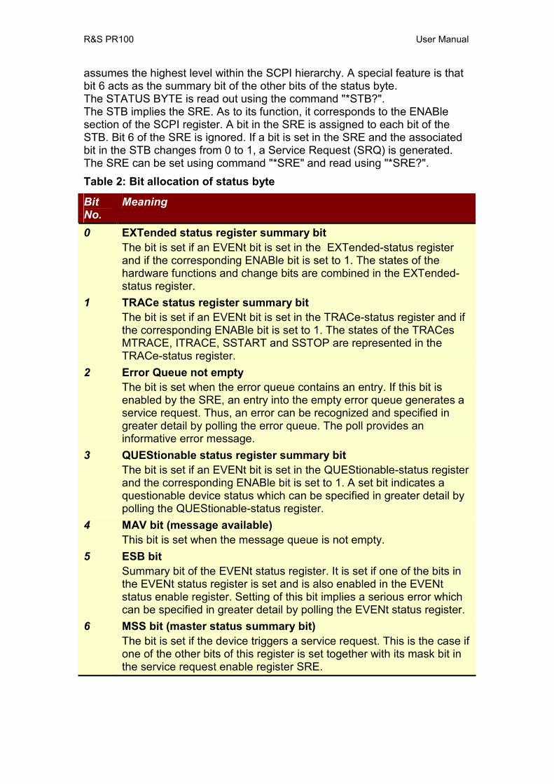
R&S PR100 User Manual
assumes the highest level within the SCPI hierarchy. A special feature is that bit 6 acts as the summary bit of the other bits of the status byte. The STATUS BYTE is read out using the command "*STB?". The STB implies the SRE. As to its function, it corresponds to the ENABle section of the SCPI register. A bit in the SRE is assigned to each bit of the STB. Bit 6 of the SRE is ignored. If a bit is set in the SRE and the associated bit in the STB changes from 0 to 1, a Service Request (SRQ) is generated. The SRE can be set using command "*SRE" and read using "*SRE?". Table 2: Bit allocation of status byte
Bit No.
Meaning
0 EXTended status register summary bit The bit is set if an EVENt bit is set in the EXTended-status register and if the corresponding ENABle bit is set to 1. The states of the hardware functions and change bits are combined in the EXTended-status register.
1 TRACe status register summary bit The bit is set if an EVENt bit is set in the TRACe-status register and if the corresponding ENABle bit is set to 1. The states of the TRACes MTRACE, ITRACE, SSTART and SSTOP are represented in the TRACe-status register.
2 Error Queue not empty The bit is set when the error queue contains an entry. If this bit is enabled by the SRE, an entry into the empty error queue generates a service request. Thus, an error can be recognized and specified in greater detail by polling the error queue. The poll provides an informative error message.
3 QUEStionable status register summary bit The bit is set if an EVENt bit is set in the QUEStionable-status register and the corresponding ENABle bit is set to 1. A set bit indicates a questionable device status which can be specified in greater detail by polling the QUEStionable-status register.
4 MAV bit (message available) This bit is set when the message queue is not empty.
5 ESB bit Summary bit of the EVENt status register. It is set if one of the bits in the EVENt status register is set and is also enabled in the EVENt status enable register. Setting of this bit implies a serious error which can be specified in greater detail by polling the EVENt status register.
6 MSS bit (master status summary bit) The bit is set if the device triggers a service request. This is the case if one of the other bits of this register is set together with its mask bit in the service request enable register SRE.

R&S PR100 User Manual
Bit No.
Meaning
7 OPERation status register summary bit The bit is set if an EVENt bit is set in the OPERation-status register and the corresponding ENABle bit is set to 1. A set bit indicates that the device is just performing an action. The type of action can be determined by polling the OPERation-status register.
9.2.1.2 IST flag and Parallel Poll Enable (PPE) register Analogous to the SRQ message, the IST flag combines the entire status information in a single bit. It can be queried by using command "*IST?". The parallel poll enable register (PPE) determines which bits of the STB contribute to the IST flag. The bits of the STB are ANDed with the corresponding bits of the PPE. In contrast to SRE bit 6 is also used here. The IST flag results from the ORing of all results. The PPE can be set using the "*PRE" commands and read using the "*PRE?" command.
9.2.1.3 Event Status Register (ESR) and Event Status Enable (ESE) register
The ESR is already defined in IEEE 488.2. It can be compared with the EVENt section of an SCPI register. The EVENt status register can be read out using the "*ESR?" command. The ESE is the associated ENABle section. It can be set using the "*ESE" command and read using the "*ESE?" command. Table 3: Bit allocation of event status register
Bit No.
Meaning
0 Operation Complete On receipt of the command *OPC, this bit is set exactly when all previous commands have been executed.
2 Query Error This bit is set if a query which is faulty and hence cannot be executed.
3 Device-dependent error This bit is set if a device-dependent error occurs. An error message with a number between -300 and -399 or a positive error number denoting the error in greater detail is entered into the error queue (see Section 9.3).
4 Execution Error This bit is set if a received command is syntactically correct but cannot be performed for different reasons. An error message with a number between -200 and -299 denoting the error in greater detail is entered into the error queue (see Section 9.3).
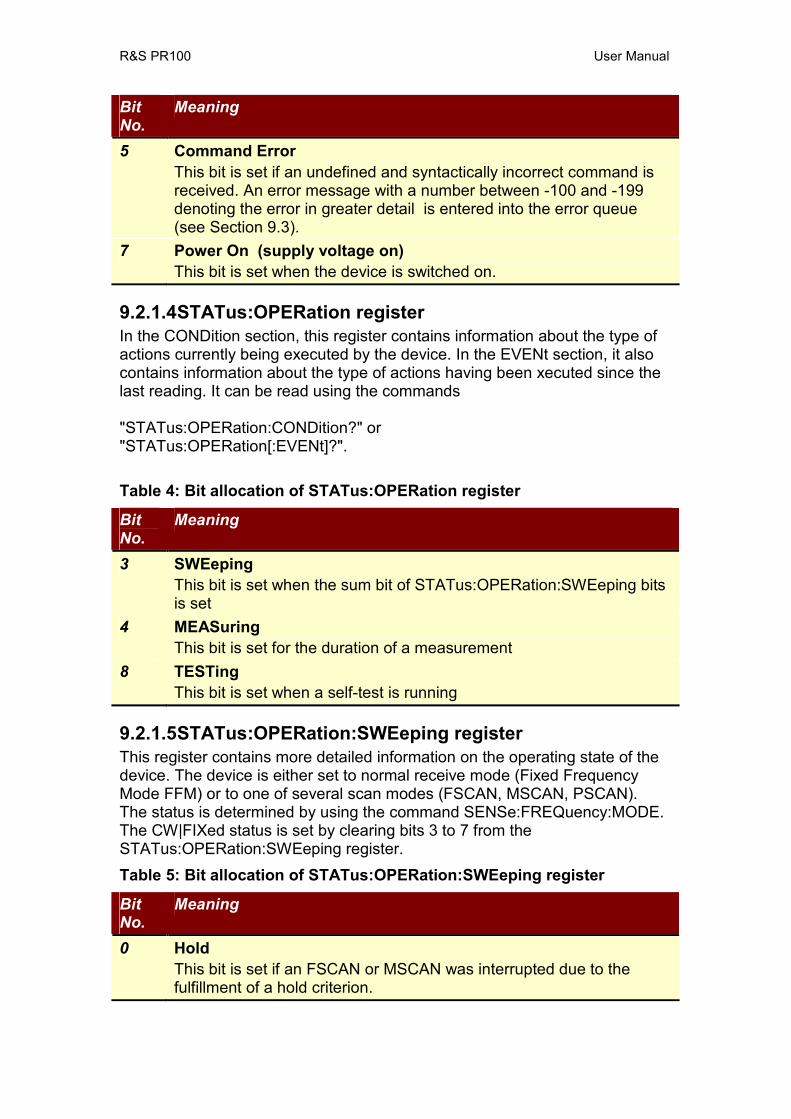
R&S PR100 User Manual
Bit No.
Meaning
5 Command Error This bit is set if an undefined and syntactically incorrect command is received. An error message with a number between -100 and -199 denoting the error in greater detail is entered into the error queue (see Section 9.3).
7 Power On (supply voltage on) This bit is set when the device is switched on.
9.2.1.4 STATus:OPERation register In the CONDition section, this register contains information about the type of actions currently being executed by the device. In the EVENt section, it also contains information about the type of actions having been xecuted since the last reading. It can be read using the commands "STATus:OPERation:CONDition?" or "STATus:OPERation[:EVENt]?". Table 4: Bit allocation of STATus:OPERation register
Bit No.
Meaning
3 SWEeping This bit is set when the sum bit of STATus:OPERation:SWEeping bits is set
4 MEASuring This bit is set for the duration of a measurement
8 TESTing This bit is set when a self-test is running
9.2.1.5 STATus:OPERation:SWEeping register This register contains more detailed information on the operating state of the device. The device is either set to normal receive mode (Fixed Frequency Mode FFM) or to one of several scan modes (FSCAN, MSCAN, PSCAN). The status is determined by using the command SENSe:FREQuency:MODE. The CW|FIXed status is set by clearing bits 3 to 7 from the STATus:OPERation:SWEeping register. Table 5: Bit allocation of STATus:OPERation:SWEeping register
Bit No.
Meaning
0 Hold This bit is set if an FSCAN or MSCAN was interrupted due to the fulfillment of a hold criterion.

R&S PR100 User Manual
Bit No.
Meaning
1 Running up This bit is set if sweeping is to be carried out in the direction of increasing frequency values or memory location numbers.
2 Running down This bit is set if sweeping is to be carried out in the direction of decreasing frequency values or memory location numbers.
3 FSCAN active This bit is set if FREQ:MODE is set to SWEep
4 MSCAN active This bit is set if FREQ:MODE is set to MSCan
5 not used, always 0 (was used for DSCAN mode in EB200) 6 not used, always 0 (was used for FASTlevcw mode in EB200) 7 not used, always 0 (was used for LIST mode in EB200) 8 PSCAN active
This bit is set if FREQ:MODE is set to PSCan
9.2.1.6 STATus:TRACe register This register contains information on ambiguous states of the traces MTRACE, ITRACE, IFPAN, SSTART and SSTOP. It can be queried with the commands STATus:TRACe:CONDition? or STATus:TRACe[:EVENt]?.

R&S PR100 User Manual
Table 6: Bit allocation of STATus:TRACe register
Bit No.
Meaning
0 MTRACE not empty This bit is set if the MTRACE contains at least one measured value.
1 MTRACE limit exceeded This bit is set if the number of measured values contained in the MTRACE exceeds the threshold given by the command TRACe:LIMit[:UPPer] MTRACE.
2 MTRACE total full This bit is set if the MTRACE is loaded with the maximum number of measured values.
3 ITRACE not empty This bit is set if the ITRACE contains at least one information value.
4 ITRACE limit exceeded This bit is set if the number of measured values contained in the ITRACE exceeds the threshold given by the command TRACe:LIMit[:UPPer] ITRACE.
5 ITRACE total full This bit is set if the ITRACE is loaded with the maximum number of information values.
6 SSTART changed This bit is set if one or several start frequencies of the current suppress table have changed.
7 SSTOP changed This bit is set if one or several stop frequencies of the current suppress table have changed.
8 IFPAN not empty This bit is set if at least one measured value is stored under IFPAN.
9 IFPAN Limit exceeded This bit is set if the number of measured values stored under IFPAN exceeds the threshold set by TRACe:LIMit[:UPPer] IFPAN.
10 IFPAN total full This bit is set if the maximal number of measured values is stored under IFPAN.
11 AUDIO not empty This bit is set if some audio data has been recorded.
12 AUDIO Limit exceeded This bit is set if the information stored under AUDIO exceeds the threshold set by TRACe:LIMit[:UPPer] AUDIO.
13 AUDIO total full This bit is set if the maximal amount of AUDIO data is stored.
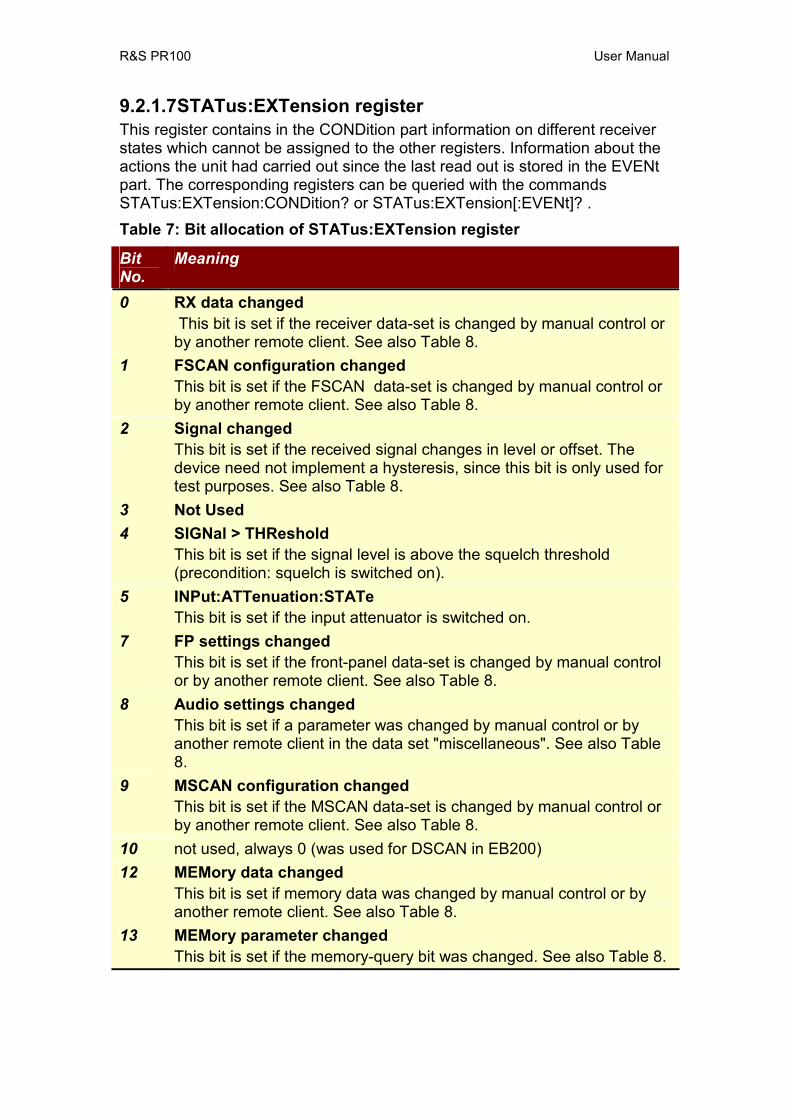
R&S PR100 User Manual
9.2.1.7 STATus:EXTension register This register contains in the CONDition part information on different receiver states which cannot be assigned to the other registers. Information about the actions the unit had carried out since the last read out is stored in the EVENt part. The corresponding registers can be queried with the commands STATus:EXTension:CONDition? or STATus:EXTension[:EVENt]? . Table 7: Bit allocation of STATus:EXTension register
Bit No.
Meaning
0 RX data changed This bit is set if the receiver data-set is changed by manual control or
by another remote client. See also Table 8. 1 FSCAN configuration changed
This bit is set if the FSCAN data-set is changed by manual control or by another remote client. See also Table 8.
2 Signal changed This bit is set if the received signal changes in level or offset. The device need not implement a hysteresis, since this bit is only used for test purposes. See also Table 8.
3 Not Used 4 SIGNal > THReshold
This bit is set if the signal level is above the squelch threshold (precondition: squelch is switched on).
5 INPut:ATTenuation:STATe This bit is set if the input attenuator is switched on.
7 FP settings changed This bit is set if the front-panel data-set is changed by manual control or by another remote client. See also Table 8.
8 Audio settings changed This bit is set if a parameter was changed by manual control or by another remote client in the data set "miscellaneous". See also Table 8.
9 MSCAN configuration changed This bit is set if the MSCAN data-set is changed by manual control or by another remote client. See also Table 8.
10 not used, always 0 (was used for DSCAN in EB200) 12 MEMory data changed
This bit is set if memory data was changed by manual control or by another remote client. See also Table 8.
13 MEMory parameter changed This bit is set if the memory-query bit was changed. See also Table 8.
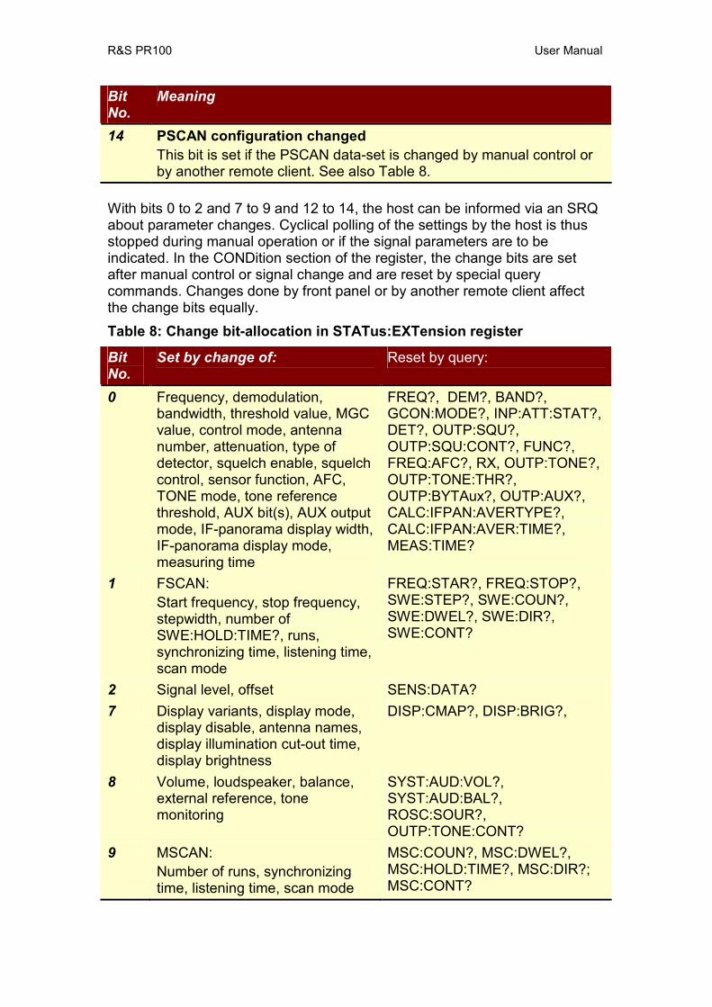
R&S PR100 User Manual
Bit No.
Meaning
14 PSCAN configuration changed This bit is set if the PSCAN data-set is changed by manual control or by another remote client. See also Table 8.
With bits 0 to 2 and 7 to 9 and 12 to 14, the host can be informed via an SRQ about parameter changes. Cyclical polling of the settings by the host is thus stopped during manual operation or if the signal parameters are to be indicated. In the CONDition section of the register, the change bits are set after manual control or signal change and are reset by special query commands. Changes done by front panel or by another remote client affect the change bits equally. Table 8: Change bit-allocation in STATus:EXTension register
Bit No.
Set by change of: Reset by query:
0 Frequency, demodulation, bandwidth, threshold value, MGC value, control mode, antenna number, attenuation, type of detector, squelch enable, squelch control, sensor function, AFC, TONE mode, tone reference threshold, AUX bit(s), AUX output mode, IF-panorama display width, IF-panorama display mode, measuring time
FREQ?, DEM?, BAND?, GCON:MODE?, INP:ATT:STAT?, DET?, OUTP:SQU?, OUTP:SQU:CONT?, FUNC?, FREQ:AFC?, RX, OUTP:TONE?, OUTP:TONE:THR?, OUTP:BYTAux?, OUTP:AUX?, CALC:IFPAN:AVERTYPE?, CALC:IFPAN:AVER:TIME?, MEAS:TIME?
1 FSCAN: Start frequency, stop frequency, stepwidth, number of SWE:HOLD:TIME?, runs, synchronizing time, listening time, scan mode
FREQ:STAR?, FREQ:STOP?, SWE:STEP?, SWE:COUN?, SWE:DWEL?, SWE:DIR?, SWE:CONT?
2 Signal level, offset SENS:DATA? 7 Display variants, display mode,
display disable, antenna names, display illumination cut-out time, display brightness
DISP:CMAP?, DISP:BRIG?,
8 Volume, loudspeaker, balance, external reference, tone monitoring
SYST:AUD:VOL?, SYST:AUD:BAL?, ROSC:SOUR?, OUTP:TONE:CONT?
9 MSCAN: Number of runs, synchronizing time, listening time, scan mode
MSC:COUN?, MSC:DWEL?, MSC:HOLD:TIME?, MSC:DIR?; MSC:CONT?
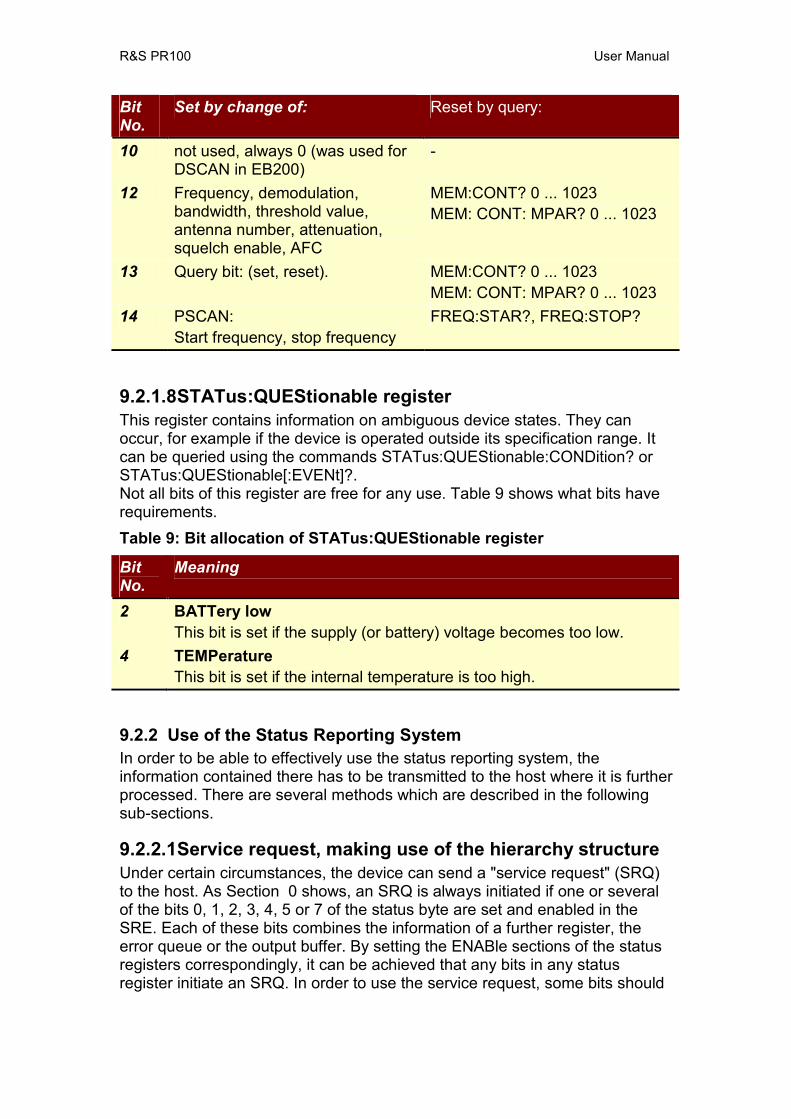
R&S PR100 User Manual
Bit No.
Set by change of: Reset by query:
10 not used, always 0 (was used for DSCAN in EB200)
-
12 Frequency, demodulation, bandwidth, threshold value, antenna number, attenuation, squelch enable, AFC
MEM:CONT? 0 ... 1023 MEM: CONT: MPAR? 0 ... 1023
13 Query bit: (set, reset). MEM:CONT? 0 ... 1023 MEM: CONT: MPAR? 0 ... 1023
14 PSCAN: Start frequency, stop frequency
FREQ:STAR?, FREQ:STOP?
9.2.1.8 STATus:QUEStionable register This register contains information on ambiguous device states. They can occur, for example if the device is operated outside its specification range. It can be queried using the commands STATus:QUEStionable:CONDition? or STATus:QUEStionable[:EVENt]?. Not all bits of this register are free for any use. Table 9 shows what bits have requirements. Table 9: Bit allocation of STATus:QUEStionable register
Bit No.
Meaning
2 BATTery low This bit is set if the supply (or battery) voltage becomes too low.
4 TEMPerature This bit is set if the internal temperature is too high.
9.2.2 Use of the Status Reporting System In order to be able to effectively use the status reporting system, the information contained there has to be transmitted to the host where it is further processed. There are several methods which are described in the following sub-sections.
9.2.2.1 Service request, making use of the hierarchy structure Under certain circumstances, the device can send a "service request" (SRQ) to the host. As Section 0 shows, an SRQ is always initiated if one or several of the bits 0, 1, 2, 3, 4, 5 or 7 of the status byte are set and enabled in the SRE. Each of these bits combines the information of a further register, the error queue or the output buffer. By setting the ENABle sections of the status registers correspondingly, it can be achieved that any bits in any status register initiate an SRQ. In order to use the service request, some bits should
R&S PR100 User Manual
be set to "1" in enable registers SRE and ESE. Only those bits need to be set that represent the situations for which a service request must be received. Examples (also see Section 0): Use command "*OPC" to generate an SRQ
• Set bit 0 in the ESE (Operation Complete) • Set bit 5 in the SRE
After completion of the settings, the device generates an SRQ. For SCPI over TCP/IP, this is a text-response “&SRQ<CR><LF>”, where <CR> is a carriage-return, and <LF> is a line-feed. A C-type string would read as: “&SRQ\r\n”. Indication of a signal during a sweep by means of an SRQ at the host
• Set bit 7 in the SRE (summary bit of the STATus:OPERation register) • Set bit 3 (SWEeping) in the STATus:OPERation:ENABle. • Set bit 3 in the STATus:OPERation:NTRansition so that the change of
SWEeping-bit 3 from 0 to 1 is also recorded in the EVENt section. • Set bit 0 in STATus:OPERation:SWEeping:ENABle • Set bit 0 in STATus:OPERation:SWEeping:PTRansition so that the
change of hold-bit 0 from 0 to 1 is also recorded in the EVENt section. The device generates an SRQ after a signal has been found. Once an SRQ has been received, the contents of the status-byte register can be polled. For SCPI over TCP/IP, polling is done by sending the string “&POL”. The PR100 device then answers with the string “&<value><CR><LF>”, where <value> is the decimal value of the contents of the STB. The SRQ is the only possibility for the device to become active on its own. Each host program should set the device so that a service request is initiated in case of malfunction. The program should react appropriately to the service request.
9.2.2.2 Query by means of commands Each part of every status register can be read by means of queries. Only one number is returned which represents the bit pattern of the register queried. The format of the number can be set by the FORMat:SREGister command. Queries are usually used after an SRQ in order to obtain more detailed information on the cause of the SRQ.
9.2.2.3 Error-queue query Each error state in the device results in an entry in the error queue. The entries of the error queue are detailed plain-text error messages which can be queried by the command SYSTem:ERRor?. Each call of SYSTem:ERRor? provides one entry from the error queue. If no error messages are stored there anymore, the device responds with 0, "No error". The error queue should be queried after every SRQ in the controller program as the entries describe the cause of an error more precisely than the status registers. Especially during the test phase of a controller program the error queue should be queried regularly since faulty commands from the controller to the device are recorded there as well.
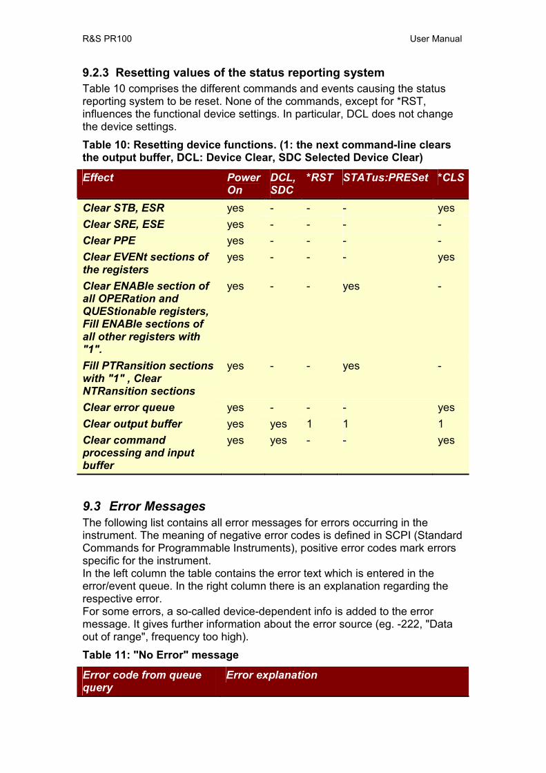
R&S PR100 User Manual
9.2.3 Resetting values of the status reporting system Table 10 comprises the different commands and events causing the status reporting system to be reset. None of the commands, except for *RST, influences the functional device settings. In particular, DCL does not change the device settings. Table 10: Resetting device functions. (1: the next command-line clears the output buffer, DCL: Device Clear, SDC Selected Device Clear)
Effect Power On
DCL, SDC
*RST STATus:PRESet *CLS
Clear STB, ESR yes - - - yes Clear SRE, ESE yes - - - -Clear PPE yes - - - -Clear EVENt sections of the registers
yes - - - yes
Clear ENABle section of all OPERation and QUEStionable registers, Fill ENABle sections of all other registers with "1".
yes - - yes -
Fill PTRansition sections with "1" , Clear NTRansition sections
yes - - yes -
Clear error queue yes - - - yes Clear output buffer yes yes 1 1 1Clear command processing and input buffer
yes yes - - yes
9.3 Error Messages The following list contains all error messages for errors occurring in the instrument. The meaning of negative error codes is defined in SCPI (Standard Commands for Programmable Instruments), positive error codes mark errors specific for the instrument. In the left column the table contains the error text which is entered in the error/event queue. In the right column there is an explanation regarding the respective error. For some errors, a so-called device-dependent info is added to the error message. It gives further information about the error source (eg. -222, "Data out of range", frequency too high). Table 11: "No Error" message
Error code from queue query
Error explanation
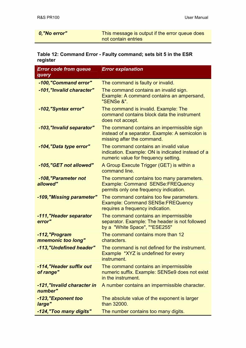
R&S PR100 User Manual
0,"No error" This message is output if the error queue does not contain entries
Table 12: Command Error - Faulty command; sets bit 5 in the ESR register
Error code from queue query
Error explanation
-100,"Command error" The command is faulty or invalid. -101,"Invalid character" The command contains an invalid sign.
Example: A command contains an ampersand, "SENSe &".
-102,"Syntax error" The command is invalid. Example: The command contains block data the instrument does not accept.
-103,"Invalid separator" The command contains an impermissible sign instead of a separator. Example: A semicolon is missing after the command.
-104,"Data type error" The command contains an invalid value indication. Example: ON is indicated instead of a numeric value for frequency setting.
-105,"GET not allowed" A Group Execute Trigger (GET) is within a command line.
-108,"Parameter not allowed"
The command contains too many parameters. Example: Command SENSe:FREQuency permits only one frequency indication.
-109,"Missing parameter" The command contains too few parameters. Example: Command SENSe:FREQuency requires a frequency indication.
-111,"Header separator error"
The command contains an impermissible separator. Example: The header is not followed by a "White Space", "*ESE255"
-112,"Program mnemonic too long"
The command contains more than 12 characters.
-113,"Undefined header" The command is not defined for the instrument. Example *XYZ is undefined for every instrument.
-114,"Header suffix out of range"
The command contains an impermissible numeric suffix. Example: SENSe9 does not exist in the instrument.
-121,"Invalid character in number"
A number contains an impermissible character.
-123,"Exponent too large"
The absolute value of the exponent is larger than 32000.
-124,"Too many digits" The number contains too many digits.
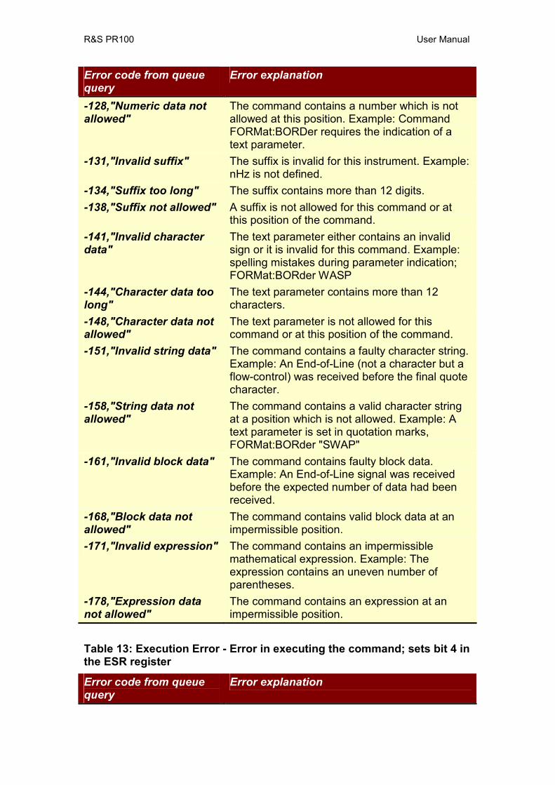
R&S PR100 User Manual
Error code from queue query
Error explanation
-128,"Numeric data not allowed"
The command contains a number which is not allowed at this position. Example: Command FORMat:BORDer requires the indication of a text parameter.
-131,"Invalid suffix" The suffix is invalid for this instrument. Example: nHz is not defined.
-134,"Suffix too long" The suffix contains more than 12 digits. -138,"Suffix not allowed" A suffix is not allowed for this command or at
this position of the command. -141,"Invalid character data"
The text parameter either contains an invalid sign or it is invalid for this command. Example: spelling mistakes during parameter indication; FORMat:BORder WASP
-144,"Character data too long"
The text parameter contains more than 12 characters.
-148,"Character data not allowed"
The text parameter is not allowed for this command or at this position of the command.
-151,"Invalid string data" The command contains a faulty character string. Example: An End-of-Line (not a character but a flow-control) was received before the final quote character.
-158,"String data not allowed"
The command contains a valid character string at a position which is not allowed. Example: A text parameter is set in quotation marks, FORMat:BORder "SWAP"
-161,"Invalid block data" The command contains faulty block data. Example: An End-of-Line signal was received before the expected number of data had been received.
-168,"Block data not allowed"
The command contains valid block data at an impermissible position.
-171,"Invalid expression" The command contains an impermissible mathematical expression. Example: The expression contains an uneven number of parentheses.
-178,"Expression data not allowed"
The command contains an expression at an impermissible position.
Table 13: Execution Error - Error in executing the command; sets bit 4 in the ESR register
Error code from queue query
Error explanation

R&S PR100 User Manual
Error code from queue query
Error explanation
-200,"Execution error" Error during execution of the command. -211, “Trigger Ignored” A trigger is igored when e.g. it occurs before the
measuring time has elapsed. This can happen when the trigger time is smaller than the measuring time.
-221,"Settings conflict" There is a settings conflict between two parameters.
-222,"Data out of range" The parameter value is outside the permissible range of the instrument.
-223,"Too much data" The command requires more storage for data than is available. E.g. A list of frequencies may only contain 5 elements, and the command tries to add a sixth.
-240,"Hardware error" Hardware error is not further specified. -241,"Hardware missing" The command cannot be executed due to
missing hardware. Example: An option is not installed.
-292,"Referenced name does not exist"
An unknown name was sent as a parameter. Example: An unknown file name is to be deleted, MMEM:RDIR “Flubber”
-293,"Referenced name already exists"
The name is defined twice. Example: An file already exists.
Table 14: Device Specific Error; sets bit 3 in the ESR register
Error code from queue query
Error explanation
-300,"Device-specific error"
Some data in memory not valid.
-350,"Queue overflow" This error code is entered into the queue instead of the actual error code if the queue is full. It indicates that an error has occurred but not been accepted. The queue can accept 5 entries.
Table 15: Query Error; sets bit 2 in the ESR register
Error code from queue query
Error explanation
-400,"Query error" General error which is not further specified. -410,"Query
INTERRUPTED" The query has been interrupted. Example: After a query, the instrument receives new data before the response has been sent completely.
-420,"Query The query is incomplete. Example: The

R&S PR100 User Manual
UNTERMINATED" instrument is addressed as a talker and receives incomplete data.
-430,"Query DEADLOCKED"
The query cannot be processed. Example: The input and output buffers are full, the instrument cannot continue the operation.
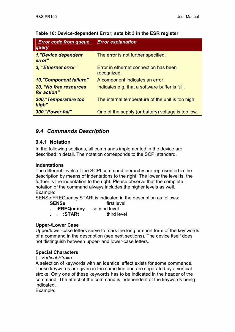
R&S PR100 User Manual
Table 16: Device-dependent Error; sets bit 3 in the ESR register
Error code from queue query
Error explanation
1,"Device dependent error"
The error is not further specified.
3, “Ethernet error” Error in ethernet connection has been recognized.
10,"Component failure" A component indicates an error. 20, “No free resources for action”
Indicates e.g. that a software buffer is full.
200,"Temperature too high"
The internal temperature of the unit is too high.
300,"Power fail" One of the supply (or battery) voltage is too low.
9.4 Commands Description
9.4.1 Notation In the following sections, all commands implemented in the device are described in detail. The notation corresponds to the SCPI standard. Indentations The different levels of the SCPI command hierarchy are represented in the description by means of indentations to the right. The lower the level is, the further is the indentation to the right. Please observe that the complete notation of the command always includes the higher levels as well. Example: SENSe:FREQuency:STARt is indicated in the description as follows:
SENSe first level . :FREQuency second level . . :STARt third level
Upper-/Lower Case Upper/lower-case letters serve to mark the long or short form of the key words of a command in the description (see next sections). The device itself does not distinguish between upper- and lower-case letters. Special Characters | - Vertical Stroke A selection of keywords with an identical effect exists for some commands. These keywords are given in the same line and are separated by a vertical stroke. Only one of these keywords has to be indicated in the header of the command. The effect of the command is independent of the keywords being indicated. Example:
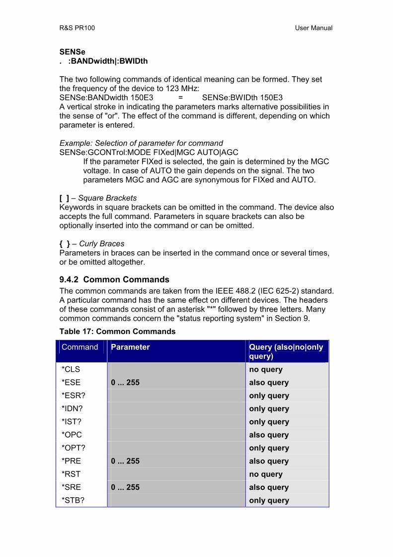
R&S PR100 User Manual
SENSe . :BANDwidth|:BWIDth The two following commands of identical meaning can be formed. They set the frequency of the device to 123 MHz: SENSe:BANDwidth 150E3 = SENSe:BWIDth 150E3 A vertical stroke in indicating the parameters marks alternative possibilities in the sense of "or". The effect of the command is different, depending on which parameter is entered. Example: Selection of parameter for command SENSe:GCONTrol:MODE FIXed|MGC AUTO|AGC
If the parameter FIXed is selected, the gain is determined by the MGC voltage. In case of AUTO the gain depends on the signal. The two parameters MGC and AGC are synonymous for FIXed and AUTO.
[ ] – Square Brackets Keywords in square brackets can be omitted in the command. The device also accepts the full command. Parameters in square brackets can also be optionally inserted into the command or can be omitted. – Curly Braces Parameters in braces can be inserted in the command once or several times, or be omitted altogether.
9.4.2 Common Commands The common commands are taken from the IEEE 488.2 (IEC 625-2) standard. A particular command has the same effect on different devices. The headers of these commands consist of an asterisk "*" followed by three letters. Many common commands concern the "status reporting system" in Section 9. Table 17: Common Commands
Command Parameter Query (also|no|only query)
*CLS no query *ESE 0 ... 255 also query *ESR? only query *IDN? only query *IST? only query *OPC also query *OPT? only query *PRE 0 ... 255 also query *RST no query *SRE 0 ... 255 also query *STB? only query
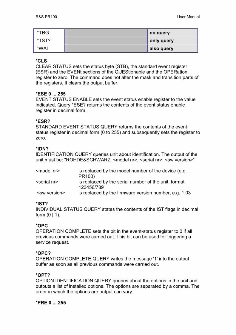
R&S PR100 User Manual
*TRG no query *TST? only query *WAI also query
*CLS CLEAR STATUS sets the status byte (STB), the standard event register (ESR) and the EVENt sections of the QUEStionable and the OPERation register to zero. The command does not alter the mask and transition parts of the registers. It clears the output buffer. *ESE 0 ... 255 EVENT STATUS ENABLE sets the event status enable register to the value indicated. Query *ESE? returns the contents of the event status enable register in decimal form. *ESR? STANDARD EVENT STATUS QUERY returns the contents of the event status register in decimal form (0 to 255) and subsequently sets the register to zero. *IDN? IDENTIFICATION QUERY queries unit about identification. The output of the unit must be: "ROHDE&SCHWARZ, <model nr>, <serial nr>, <sw version>” <model nr> is replaced by the model number of the device (e.g.
PR100) <serial nr> is replaced by the serial number of the unit, format
123456/789 <sw version> is replaced by the firmware version number, e.g. 1.03 *IST? INDIVIDUAL STATUS QUERY states the contents of the IST flags in decimal form (0 | 1). *OPC OPERATION COMPLETE sets the bit in the event-status register to 0 if all previous commands were carried out. This bit can be used for triggering a service request. *OPC? OPERATION COMPLETE QUERY writes the message '1' into the output buffer as soon as all previous commands were carried out. *OPT? OPTION IDENTIFICATION QUERY queries about the options in the unit and outputs a list of installed options. The options are separated by a comma. The order in which the options are output can vary. *PRE 0 ... 255

R&S PR100 User Manual
PARALLEL-POLL REGISTER ENABLE sets parallel poll enable register to the value indicated. Query *PRE? returns the contents of the parallel poll enable register in decimal form. *RST RESET sets the device to a defined default status. The default setting is indicated in the description of the commands. *SRE 0 ... 255 SERVICE REQUEST ENABLE sets the service request enable register to the value indicated. Bit 6 (MSS mask bit) remains 0. This command determines under which conditions a service request is triggered. Query *SRE? reads the contents of the service request enable register in decimal form. Bit 6 is always 0. *STB? READ STATUS BYTE QUERY reads out the contents of the status byte in decimal form. *TRG TRIGGER triggers the same actions as the INITiate:CONM[:IMMediate] command. *TST? SELFTEST QUERY triggers the module state test and yields a figure which is to be interpreted as the bit field: Result = 0
All modules are ok. Result ≠ 0
There is a fault in one or several modules. The information about the possible error can be queried by means of the SYSTem:ERRor? Command.
*WAI WAIT-to-CONTINUE only permits the servicing of the subsequent commands after all preceding commands have been executed and all signals have settled.
10 Instrument Behaviour The behaviour of the Orion MR is defined by the following aspects:
• Error Situations There are several types of error situations that apply to a number of, otherwise unrelated, commands
• Ranging and Rouding This applies to all commands that set a value. Ideally, the user supplies a value that is within the instrument’s range and corresponds with its resolution. When this ideal situation is not met, ranging and rounding must be applied to get a value the instrument can handle.
R&S PR100 User Manual
• Value Representation This applies to all commands that return a value. This value must be presented to the user with an adequate accuracy.
• Default Values Each parameter that can be set or queried via SCPI has a default value after applying the *RST command.
• Instrument States The behaviour of a command may vary between instrument states
10.1 Error Situations The common behaviour of the instrument in error situations is as shown in the list below (unless other behaviour has been explicitly specified for a specific command or query):
• Do a command or query in an instrument state in which the command/query is not supported The error -221 “Settings conflict” is returned
• Set a parameter to such a state that it conflicts with other parameters The error -221 “Settings conflict” is returned. The device does not adapt other parameters in order to try to resolve a settings conflict. The new parameter setting is rejected and the device setup remains unchanged.
• Query a measurement result that is not available SCPI outputs NAN instead of a value acc. to SCPI standard Section 7.2.1. Note that NAN is output as 9.91E37, as is also described in [SCPI] and [Orion SCPI].
Differences with EB200/EM050 Devices:
• A similar error situation may produce a different error code and message on the Orion MR and on the EB200/EM050.
10.2 Ranging and Rounding Each parameter of the device that takes a value has a maximum and a minimum. In addition, each parameter has a resolution. The approach for setting a value for a parameter is as follows:
• if the supplied value is beyond its maximum or below its minimum, return error -222 “Data out of range” without changing the parameter. The device does not adapt other parameters in order to try to resolve a data out of range situation. The new parameter setting is rejected and the device setup remains unchanged.
• round the supplied value to the device’s resolution. For specific parameters (e.g. bandwidth), Orion can choose to round up or down instead of rounding towards the closest value.
• if the supplied value results in an error situation, return an error appropriate for that situation without changing the parameter.

R&S PR100 User Manual
• accept the rounded value. Differences with EB200/EM050 Devices:
• The EB200 operates as described above, but does rounding before the range checking. That means that a value that is out of range, but within the resolution of the minimum or maximum, is accepted.
10.3 Value Representation When a value (from either a measurement or from a setting) is presented to the user by means of a response to an SCPI query, it is presented with the accuracy that is used by the instrument. Exceptions to this rule will be documented.
10.4 Default Values The device has only one set of default values: That means that both the user interface and the remote interface (SCPI) use the same default values for parameters. This is identical to the EB200/EM050 devices. The EB200 and the Orion MR do not use the same set of default parameters and their values are not the same either.
10.5 Instrument States
10.5.1 Introduction In order to get a good overview of how the Orion MR reacts to SCPI commands, one should study the various instrument states the device can have. These states dictate if an SCPI command is rejected or allowed. When a command is allowed, two situations can be distinguished:
• the command triggers a state transition and executes from there • the command executes in the current state
This section describes the instrument states and shows the commands that trigger state transitions. A full description of these commands is part of the subsequent chapters. Each command is assigned to one or more states in which it can execute.
10.5.2 MR States The various states of the Orion MR are depicted below:
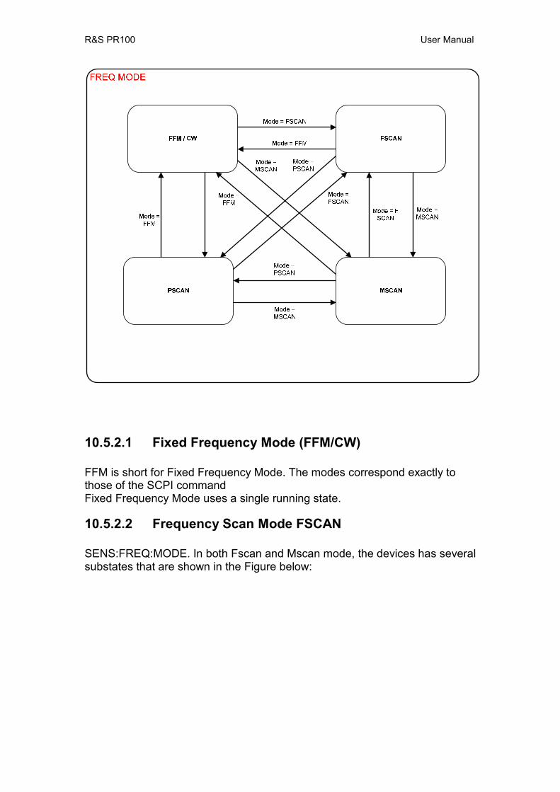
R&S PR100 User Manual
10.5.2.1 Fixed Frequency Mode (FFM/CW) FFM is short for Fixed Frequency Mode. The modes correspond exactly to those of the SCPI command Fixed Frequency Mode uses a single running state.
10.5.2.2 Frequency Scan Mode FSCAN SENS:FREQ:MODE. In both Fscan and Mscan mode, the devices has several substates that are shown in the Figure below:

R&S PR100 User Manual
STOPPED
RUNNING
SIGNAL
NO SIGNAL
(State == RUN+ AND Key(RUN-)) OR(State == RUN- AND Key(RUN+))
tm(t_level)Calculate level
level >= Squelch ANDt_dwell > 0
Start tm(t_dwell) (State == RUN+ && Key(RUN+)) OR(State == RUN- && Key(RUN-))
level < SquelchReset tm(no_sig)Start tm(no_sig)
tm(t_dwell) NOT PassedSignal >= Squelch
Key(Run+) OR Key(Run-) OR
tm(t_dwell)
Key(Run+ ORKey(Run-)
(State == RUN+ && Key(RUN+)) OR(State == RUN- && Key(RUN-))
tm(t_dwell) ORSignal < Squelch AND tm(no_sig)
tm(t_level)Calculate level
tm(t_level)Calculate level
Figure 4 Frequency Scan Mode States

R&S PR100 User Manual
10.5.2.3 Memory Scan Mode MSCAN Memory Scan Mode shows exactly the same behaviour as the Frequency Scan Mode in the way of internal states as presented in Figure 4.
10.5.2.4 Panorama Scan Mode PSCAN In Panorama Scan Mode only states Stopped and Running are applicable.
11 Commands Reference This chapter describes the SCPI commands that are specific to the Orion MR product. They are additional to the list in Chapter 4 of [Orion SCPI].
11.1 Common Commands The commands listed in this section are taken from the IEEE 488.2 (IEC 625-2) standard and are supported by all instruments. However each instrument type may respond differently, e.g. the option query comannd returns all installed options which might be instrument specific.
*OPT? OPTION IDENTIFICATION QUERY queries about the options in the unit and outputs a list of installed options. The options are seperated by a comma. The returned optionlist is fixed and options which are not installed have a value equal to zero. Installed options are indicated by having the abbreviation used in the optionlist below: Panorama Scan PS Remote Control RC Fieldstrength Measurement FS Example:
*OPT? returned PS,0,RC,0,FS,0,0 This instrument has the following options installed:
• Panorama Scan • Reserved • Remote Control • Reserved • Fieldstrength Measurement • Reserved • Reserved
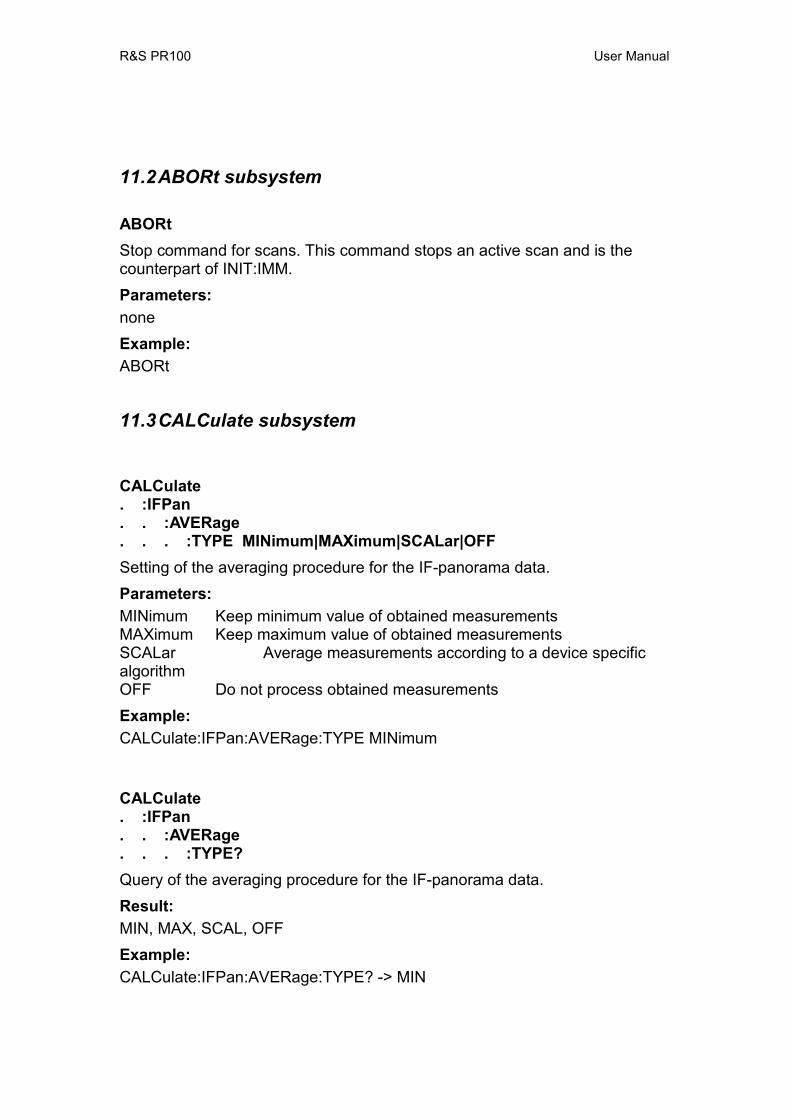
R&S PR100 User Manual
11.2 ABORt subsystem
ABORt Stop command for scans. This command stops an active scan and is the counterpart of INIT:IMM. Parameters: none Example: ABORt
11.3 CALCulate subsystem
CALCulate . :IFPan . . :AVERage . . . :TYPE MINimum|MAXimum|SCALar|OFF Setting of the averaging procedure for the IF-panorama data. Parameters: MINimum Keep minimum value of obtained measurements MAXimum Keep maximum value of obtained measurements SCALar Average measurements according to a device specific algorithm OFF Do not process obtained measurements Example: CALCulate:IFPan:AVERage:TYPE MINimum
CALCulate . :IFPan . . :AVERage . . . :TYPE? Query of the averaging procedure for the IF-panorama data. Result: MIN, MAX, SCAL, OFF Example: CALCulate:IFPan:AVERage:TYPE? -> MIN

R&S PR100 User Manual
CALCulate . :IFPan . . :CLEar Restart of the averaging function for the IF-panorama data. The value obtained from IF-panorama measurements thus far is deleted, and a new value is obtained. Parameters: none Example: CALCulate:IFPan:CLEar
CALCulate . :IFPan . . :MARKer:MAXimum[:PEAK] Centering of the IF-panorama spectrum to the absolute-level maximum. This changes the receiver frequency SENS:FREQ:CW. Parameters: none Example: CALCulate:IFPan:MARKer:MAXimum CALCulate:IFPan:MARKer:MAXimum

R&S PR100 User Manual
CALCulate . :IFPan . . :MARKer:MAXimum:LEFT The center of the IF-panorama spectrum is moved toward the nearest maximum on the left. This changes the receiver frequency SENS:FREQ:CW. Parameters: none Example: CALCulate:IFPan:MARKer:LEFT CALCulate . :IFPan . . :MARKer:MAXimum:RIGHt The center of the IF-panorama spectrum is moved toward the nearest maximum on the right. This changes the receiver frequency SENS:FREQ:CW. Parameters: none Example: CALCulate:IFPan:MARKer:RIGHt
R&S PR100 User Manual
CALCulate . :PSCan . . :AVERage . . . :TYPE MINimum|MAXimum|SCALar| OFF Setting of the averaging procedure for the panorama-scan data. Each FFT sample is processed separately, e.g. for the MAXimum type a maximum value is kept for each bin in a panorama scan. Parameters: MINimum Keep minimum value of obtained measurements MAXimum Keep maximum value of obtained measurements SCALar Average measurements over the measurement time OFF Do not process obtained measurements Example: CALCulate:PSCan:AVERage:TYPE MINimum CALCulate . :PSCan . . :AVERage . . . :TYPE? Query of the averaging procedure for the panorama-scan data. Result: MIN, MAX, SCAL, OFF Example: CALCulate:PSCan:AVERage:TYPE? -> MIN

R&S PR100 User Manual
CALCulate . :PSCan . . :CLEar Restart of the averaging function for the panorama-scan data. The values for each bin in the FFTs measured thus far are deleted, and new values are obtained. Parameters: none Example: CALCulate:PSCan:CLEar CALCulate . :PSCan . . :MARKer:MAXimum[:PEAK] Moves the reveiver frequency to the FFT-bin with the absolute-level maximum in the RF panorama. This changes the receiver frequency SENS:FREQ:CW Parameters: none Example: CALCulate:PSCan:MARKer:MAXimum
R&S PR100 User Manual
CALCulate . :PSCan . . :MARKer:MAXimum:LEFT Moves the reveiver frequency to the maximum that lies to the left of the current frequency in the RF-panorama scan. This changes the receiver frequency SENS:FREQ:CW. If squelch is on, only the maxima that are above the squelch level are taken into account. Parameters: none Example: CALCulate:PSCan:MARKer:LEFT CALCulate . :PSCan . . :MARKer:MAXimum:RIGHt Moves the reveiver frequency to the maximum that lies to the right of the current frequency in the RF-panorama scan. This changes the receiver frequency SENS:FREQ:CW. If squelch is on, only the maxima that are above the squelch level are taken into account. Parameters: none Example: CALCulate:PSCan:MARKer:RIGHt
11.4 DIAGnostic subsystem
DIAGnostic . [:SERVice] . . :ADAPter . . . [:STATe]? Query whether the instrument is currently being powered by a mains adapter. Result: 0 Instrument is powered by internal battery. 1 Instrument is powerred by mains adapter. Example: DIAGnostic:ADAPter? -> 1

R&S PR100 User Manual
DIAGnostic . [:SERVice] . . :INFO . . . :SVERsion? Query of the software version. Parameters: none Result: Software version Example: DIAGnostic:INFO:SVERsion? -> V[12.34] “V” indicates this is a release version, “B” is for beta versions 12 is the major version number 24 is the minor version num
11.5 DISPlay subsystem
DISPlay . :BRIGhtness <numeric_value>|MINimum|MAXimum Controls the brightness of the display backlighting. Parameters: <numeric_value> brightness of backlighting from 0.00 to 1.00
0.00 = backlighting off 1.00 = full backlighting
MINimum|MAXimum backlighting off|full backlighting Remark: The brightness can be set between 0.00 and 1.00 with 2 decimals resolution. Example: DISPlay:BRIGhtness 0.45
DISPlay . :BRIGhtness? [MINimum|MAXimum] Query of brightness of display backlighting. Parameter: none query of current brightness MINimum|MAXimum query of lowest|highest brightness Result: Brightness of backlighting from 0.00 to 1.00

R&S PR100 User Manual
Example: DISPlay:BRIGhtness? -> 0.45
R&S PR100 User Manual
DISPlay . :CMAP:DEFault Selection of display-colors for indoor use. Parameters: none Example: DISPlay:CMAP:DEFault DISPlay . :CMAP INDoor|OUTDoor|BW Selection of display color-scheme. Parameters: INDoor Color-scheme for indoor use OUTDoor Color-scheme for outdoor use BW Black and White color-scheme Example: DISPlay:CMAP OUTDoor DISPlay . :CMAP? Query of the currently selected color-scheme. Parameters: none Result: IND, OUTD, BW Example: DISPlay:CMAP? -> OUTD
R&S PR100 User Manual
DISPlay . :DATE . . :FORMat DDMMyyyy|MMDDyyyy Sets the date format used for display Parameters: DDMMyyyy E.g. 31/12/2005 MMDDyyyy E.g. 12/31/2005 Example: DISPlay:DATE:FORMat MMDDyyyy
DISPlay . :DATE . . :FORMat? Query the date format used for display Parameter: none Result: DDMM, MMDD Example: DISPlay:DATE:FORMat? -> MMDD

R&S PR100 User Manual
DISPlay . :FSTRength <Boolean> Enable or disable the display of field strength information. Note that the information can only be shown if a valid K-factor has been set. Parameters: ON enable field-strength display OFF disable field-strength display Example: DISPlay:FSTRength OFF
R&S PR100 User Manual
DISPlay . :FSTRength? Query whether field-strength is displayed or not Parameters: none Result: 0 OFF 1 ON Example: DISPlay:FSTRength? -> 0 DISPlay . :IFPan . . :LEVel . . . :RANGe <numeric_value>|MINimum|MAXimum Sets the range of signal levels that is displayed in a panorama view. Different levels within this range can be distinguished in the view. The top-end of the range is equal to “DISP:IFP:LEV:REF”. Parameters: <numeric_value> signal-level range in dBµVMINimum|MAXimum minimum|maximum range Example: DISPlay:IFPan:LEVel:RANGe 30
R&S PR100 User Manual
DISPlay . :IFPan . . :LEVel . . . :RANGe? [MINimum|MAXimum] Query the range of signal levels that is displayed in an IFPan view Parameter: none query of current range MINimum|MAXimum query of minimum|maximum range Result: signal-level range in dBµVExample: DISPlay:IFPan:LEVel:RANGe? -> 30 DISPlay . :IFPan . . :LEVel . . . :REFerence <numeric_value>|MINimum|MAXimum Sets the maximum signal-level that can be displayed in an IFPan view. Parameters: <numeric_value> reference level in dBµVMINimum|MAXimum lowerst|highest reference level Example: DISPlay:IFPan:LEVel:REFerence 40
R&S PR100 User Manual
DISPlay . :IFPan . . :LEVel . . . :REFerence? [MINimum|MAXimum] Query of maximum signal-level that can be displayed in an IFPan view Parameter: none query of current reference level MINimum|MAXimum query of lowest|highest reference level Result: reference level in dBµVExample: DISPlay:IFPan:LEVel:REFerence? -> 40 DISPlay . :LEVel . . :LIMit . . . :MINimum <numeric_value>|MINimum|MAXimum Sets the lower limit for the level-bar display. Signal-level with lower values cannot be distinguished (i.e. are displayed with the same size of level bar). This setting only applies if the tone mode if off (OUTP:TONE:STAT OFF). If tone mode is on, the device determines the lower limit itself. Parameters: <numeric_value> signal-level in dBµVMINimum|MAXimum lowest|highest signal-level Example: DISPlay:LEVel:LIMit:MINimum 20
R&S PR100 User Manual
DISPlay . :LEVel . . :LIMit . . . :MINimum? [MINimum|MAXimum] Query of lower limit for the level-bar display This setting only applies if the tone mode if off (OUTP:TONE:STAT OFF). If tone mode is on, the device determines the lower limit itself. Parameter: none query of current signal-level in dBµVMINimum|MAXimum query of lowest|highest signal-level Result: signal-level in dBµVExample: DISPlay:LEVel:LIMit:MINimum? -> 20 DISPlay . :LEVel . . :RANGe <numeric_value>|MINimum|MAXimum Sets the range of signal levels that is displayed in a level-bar view. Different levels within this range can be distinguished in the panorama view. The top-end of the range is equal to “DISP:LEV:LIM:MIN”. This setting only applies if the tone mode if off (OUTP:TONE:STAT OFF). If tone mode is on, the device determines the lower limit itself. Parameters: <numeric_value> signal-level range in dBµVMINimum|MAXimum minimum|maximum range Remark: The range can be set in discrete steps. Intermediate values are therefore rounded to the nearest discrete value. Example: DISPlay:LEVel:RANGe 30
R&S PR100 User Manual
DISPlay . :LEVel . . :RANGe? [MINimum|MAXimum] Query range of signal levels that is displayed in a level-bar view This setting only applies if the tone mode if off (OUTP:TONE:STAT OFF). If tone mode is on, the device determines the lower limit itself. Parameter: none query of current range MINimum|MAXimum query of minimum|maximum range Result: signal-level range in dBµVExample: DISPlay:LEVel:RANGe? -> 30 DISPlay . :PSCan . . :LEVel . . . :RANGe <numeric_value>|MINimum|MAXimum Sets the range of signal levels that is displayed in a panorama view. Different levels within this range can be distinguished in the view. The top-end of the range is equal to “DISP:PSCAN:LEV:REF”. Parameters: <numeric_value> signal-level range in dBµVMINimum|MAXimum minimum|maximum range Example: DISPlay:PSCAN:LEVel:RANGe 30

R&S PR100 User Manual
DISPlay . :PSCan . . :LEVel . . . :RANGe? [MINimum|MAXimum] Query the range of signal levels that is displayed in a panorama view Parameter: none query of current range MINimum|MAXimum query of minimum|maximum range Result: signal-level range in dBµVExample: DISPlay:PSCAN:LEVel:RANGe? -> 30 DISPlay . :PSCan . . :LEVel . . . :REFerence <numeric_value>|MINimum|MAXimum Sets the maximum signal-level that can be displayed in a panorama view. Parameters: <numeric_value> reference level in dBµVMINimum|MAXimum lowerst|highest reference level Example: DISPlay:PSCAN:LEVel:REFerence 40
R&S PR100 User Manual
DISPlay . :PSCan . . :LEVel . . . :REFerence? [MINimum|MAXimum] Query of maximum signal-level that can be displayed in a panorama view Parameter: none query of current reference level MINimum|MAXimum query of lowest|highest reference level Result: reference level in dBµVExample: DISPlay:PSCAN:LEVel:REFerence? -> 40 DISPlay . :WATerfall . . :CMAP <color map> Sets the color map that is used for converting signal-levels to colors in the waterfall display. Possible color maps can be retrieved with “DISP:WAT:CMAP:CAT?”. Parameters: <color map> string with the name of the color map. Note that the full string must be provided, no SCPI-like abbreviation applies here. Example: DISPlay:CMAP “Black-White”
R&S PR100 User Manual
DISPlay . :WATerfall . . :CMAP? Query the current color map for waterfall display Parameter: none Result: string with the name of the color map Example: DISPlay:CMAP? -> “Black-White” DISPlay . :WATerfall . . :CMAP . . . :CATalog? Produces a list of all available color maps as a comma separated list Parameter: none Result: comma separated list of color maps Example: DISPlay:CMAP? -> “Default”,“Green-Yellow”,“Green-Blue”,“Black-White”,“Red-Purple”,“ Blue-Black”
R&S PR100 User Manual
DISPlay . :WATerfall . . :CMAP . . . :RANGe <numeric_value>|MINimum|MAXimum Determines the signal-level range over which distinguishing colors are assigned to different signal levels. The range starts at the threshold (DISP:WAT:CMAP:THR) as the lower end of the range. Parameters: <numeric_value> range in dBµVMINimum|MAXimum lowest|highest setting for the range Example: DISPlay:WATerfall:CMAP:RANGe 30 DISPlay . :WATerfall . . :CMAP . . . :RANGe? [MINimum|MAXimum] Query of signal-level range for color coding in waterfall display Parameter: none query of currentrange in dBµVMINimum|MAXimum query of lowest|highest range setting Result: range in dBµVExample: DISPlay:WATerfall:CMAP:RANGe? -> 30
R&S PR100 User Manual
DISPlay . :WATerfall . . :CMAP . . . :THReshold <numeric_value>|MINimum|MAXimum Signal levels below this threshold all get the same background color in the waterfall display. I.e. no distinguishing color is assigned to different signal levels below the threshold. Parameters: <numeric_value> threshold in dBµVMINimum|MAXimum lowest|highest setting for the threshold Example: DISPlay:WATerfall:CMAP:THR 20 DISPlay . :WATerfall . . :CMAP . . . :THReshold? [MINimum|MAXimum] Query of signal threshold for color coding in waterfall display Parameter: none current threshold in dBµVMINimum|MAXimum query of lowest|highest setting for the threshold Result: threshold in dBµVExample: DISPlay:WATerfall:CMAP:THR? -> 20
R&S PR100 User Manual
DISPlay . :WATerfall . . :HOLD . . . [:STATe] <Boolean > Freezes the waterfall. When the state is OFF, the waterfall is frozen. In case the state is ON, the waterfall runs again. Parameters: ON waterfall runs OFF waterfall is frozen Example: DISPlay:WATerfall:HOLD ON DISPlay . :WATerfall . . :HOLD . . . [:STATe]? Query of the waterfall state. Parameter: none Result: 0, 1 Example: DISPlay:WATerfall:HOLD? -> 1
R&S PR100 User Manual
DISPlay . :WATerfall . . :SPEed <numeric_value>|MINimum|MAXimum Controls the speed of the waterfall display. Parameters: <numeric_value> number of lines per second MINimum|MAXimum slowest|fastest speed Example: DISPlay:WATerfall:SPEed 10 DISPlay . :WATerfall . . :SPEed? [MINimum|MAXimum] Query of speed of the waterfall display. Parameter: none query of current brightness MINimum|MAXimum query of lowest|highest speed Result: lines per second Example: DISPlay:WATerfall:SPEed? -> 10

R&S PR100 User Manual
DISPlay . :WINDow <display> Controls what is displayed. In case a window is chosen that is incompatible with the current scan mode (see SENS:FREQ:MODE), an error is generated: -221, “Settings conflict”, and no change is made. In case the MR is put into a mode that is incompatible with the currently selected display mode, the display mode defaults to “RX + Spectrum”. Parameters: display See “DISP:WIND:CAT?” for a list of possible displays Example: DISPlay:WINDow “RX + Spectrum” DISPlay . :WINDow? Query of current display Parameter: none Result: See “DISP:WIND:CAT?” Example: DISPlay:WINDow? -> “RX + Spectrum”

R&S PR100 User Manual
DISPlay . :WINDow . . :CATalog? Query of available displays. Parameter: none Result: “RX Only” Receive information in whole screeen (not possible with PSCAN scan mode) “RX + Spectrum” Receive information in upper part and spectrum in lower part of screen “Spectrum” Spectrum in whole screeen “Spectrum + Waterfall” Spectrum in upper part and waterfall in lower part of screen “Waterfall” Waterfall in whole screen “Dual Spectrum” Dual spectrum: IFPan spectrum in upper part and PSCAN spectrum in lower part (not possible with Memory and Frequency scan modes) Example: DISPlay:WINDow:CATalog? -> … (See under Result)
DISPlay . :WINDow . . :FETch? Creates a screen dump of the display in PNG format and outputs it as block data Parameters: none Example: DISPlay:WINDow:FETch? -> Block data of PNG picture.
R&S PR100 User Manual
DISPlay . :WINDow . . :STORe <file name> Creates a screen dump of the display in PNG format and stores it in a file on storage card with the name <file name>. Parameters: file name Name and path of file to store the screen dump in. *RST state: None, as command is an event. Example: DISPlay:WINDow:STORe “screen.png” -> Creates “screen.png”
11.6 FORMat subsystem Each individual client specifies it’s own format meaning that different formats may be pressent at the same time between multiple clients.
FORMat . :BORDer NORMal|SWAPped Specifies whether numbers in binary data are sent with the least or most significant byte first. Binary data are data that are not in ASCii format, but in PACKed format as can be specified with the command FORMat:DATA. Parameters: NORMal MSB first, LSB last SWAPped LSB first, MSB last Example: FORMat:BORDer SWAPped
FORMat . :BORDer? Query of output order for binary data. Parameters: none Result: NORM, SWAP Result: FORMat:BORDer? -> SWAP
R&S PR100 User Manual
FORMat . [:DATA] ASCii|PACKed [, length] Specifies the output format of queries that output measurement data. The length parameter is currently only used for the ASCii setting. In this case, a length larger than zero determines the number of significant digits to be returned. When length is zero, the number of digits is determined by the device itself. Parameters: ASCii output in ASCII format according to SCPI standard. PACKed output in Orion binary format Length Number of significant digits to be returned Example: FORMat PACKed
FORMat . [:DATA]? Query of output format of the queries mentioned under the FORM:DATA command. Parameters: none Result: ASC, PACK Example: FORMat? -> PACK
FORMat . :MEMory ASCii|PACKed Specifies the output format of the query: MEMory:CONTents? Parameters: ASCii output in ASCII format according to SCPI standard. PACKed output in device specific binary format Remark: See the description of the above query for a specification of its device specific binary format. Example: FORMat:MEMory PACKed

R&S PR100 User Manual
FORMat . :MEMory? Query of output format of the queries mentioned under the FORM:MEM command. Parameters: none Result: ASC, PACK Example: FORMat:MEMory? -> PACK

R&S PR100 User Manual
FORMat . :SREGister ASCII|BINary|HEXadecimal|OCTal Specifies with which data format is used for the queries of all CONDition, EVENt, ENABle, PTRansition, NTRansition registers and all IEEE-488.2 status registers. Parameters: ASCii output as decimal figure in ASCII code (e.g. 128) BINary output as binary figure in ASCII code (e.g. #B10000000) HEXadecimal output as hexadecimal figure in ASCII code (e.g. #H80) OCTal output as octal figure in ASCII code (eg #Q200) Remark: Note that a “Q” is used as prefix for octal numbers and not an “O” to avoid confusion with the digit 0 (zero). Example: FORMat:SREGister HEXadecimal
FORMat . :SREGister? Query of output format of the queries mentioned under the FORM:SREG command. Parameters: none Result: ASC, BIN, HEX, OCT Example: FORMat:SREGister? -> HEX
11.7 INITiate subsystem
INITiate . [:IMMediate] The INITiate command is an event which starts an acquisition or measurement if the instrument mode is set to fixed frequency mode, CW, or the scanner if one of the scanner modes is active. An active scan is restarted if it was already started. Parameters: None
R&S PR100 User Manual
Remark: All M-trace, I-trace and IFPan-trace buffers are cleared after executing an INITiate command. Only the first measurement value is stored in the trace-buffers when the measurement mode is set to continuous. Values will be added until the trace-buffer is full when the mode equals periodic Example: INITiate
INITiate . :CONM . . [:IMMediate] The INITiate CONtinue Measurement is identical to the INITiate command described in the previous section except for the fact that trace buffers are not cleared and an active scan is not restarted. Using the CONTinue Measurement form appends new measurement values to the current values present in the trace buffers. Using this command when a scanner causes the scanner to select the next frequency in frequency scan mode or the next memory channel when the memory scanner is active. Parameters: None Remark: The INITate CONtinue Measurement command has no effect when the measurement mode is set to periodic. Example: INITiate:CONM

R&S PR100 User Manual
11.8 INPut subsystem
INPut . :ATTenuation . . :STATe <Boolean> Switch on/off of input attenuator. Parameters: ON attenuator on OFF attenuator off Example: INPut:ATTenuation:STATe ON
INPut . :ATTenuation . . :STATe? Query of the input attenuator setting. Parameters: none Result: 0 OFF 1 ON Example: INPut:ATTenuation:STATe? -> 1
R&S PR100 User Manual
11.9 MEASure subsystem
MEASure . :MODE CONTinuous|PERiodic In the PERiodic measurement mode all detectors are discharged after the measurement time has elapsed and the next measurement is started. Only the individual measured values per measuring period are displayed. In the CONTinuous measuring mode the measuring detector is read out every 200 ms, irrespective of the measuring time. These current measured values are displayed. Remark: Parameters: CONTinuous continuous measurement PERiodic periodic measurement Example: MEASure:MODE PERiodic
MEASure . :MODE? Query of the set measuring mode. Parameters: none Result: CONT, PER Example: MEASure:MODE? -> PER
R&S PR100 User Manual
MEASure . :TIME <numeric_value>|MINimum|MAXimum|DEFault Setting of the measuring time for all measuring functions. Remark: The measuring time has an effect on the level detectors. When the level mode is set to average, AVG, the measuring time determines the averaging time. When set to peak, PEAK, this time determines the fall time. Using fast as level method does not have any impact since it is only the current value which is measured. The measuring time also has an impact on the averaging time of the IF-panorama data. Parameters: <numeric_value> measuring time in seconds MINimum|MAXimum shortest/longest measuring time DEFault use preset measuring times Example: MEASure:TIME 50 ms MEASure:TIME DEF
MEASure . :TIME? [MINimum|MAXimum] Query of the set measuring time Parameters: none query of the current measuring time MINimum|MAXimum query of the shortest/longest measuring time Result: Measuring time in seconds; with the default measuring time being set, DEF will be output. Example: MEASure:TIME? -> 0.050000 MEASure:TIME? -> DEF
R&S PR100 User Manual
11.10 MEMory subsystem This subsystem contains all the functions necessary to operate the device’s memory locations. A Memory location can be addressed in the following ways: CURRENT the currently selected memory location 0 ... 1023 memory location 0 to memory location 1023 NEXT the next free memory location, starting from and including the current location RX the current receiver settings Not all of these addressing options are allowed for every memory command. Those that are allowed are specified. Note that the currently active memory location can be queried by the “MSCAN:CHAN?” command.
MEMory . :CLEar <mem_loc> [,<count>|MAXimum] Clearing the contents of a single memory location or a range of memory locations. Parameters: <mem_loc> CURRENT|0...1023 <count> number of memory locations to be cleared, starting from
memory location <mem_loc> As a default value, <count> = 1.
MAXimum clearing all memory locations following and including <mem_loc> Example: MEMory:CLEar 123
R&S PR100 User Manual
MEMory . :CONFig . . :CATalog? Outputs the name of the memory configuration. This name can only be modified by uploading another configuration via the MEMory:CONFig command. Parameter: none Result: Name of memory configuration file, in a format identical to that of MMEM:CAT? (see [Orion SCPI]). Example: MEMory:CONFig:CATalog? -> 3000, 120000000 SomeConfigurationName, .memlst, 1000, 14-12-2006, 19:05:03
MEMory . :CONFig <block_data> Upload and activate a configuration for memory locations. Parameters: <block_data> block data with memory configuration Example: MEMory:CONFig <block-data specific for memory configuration>
R&S PR100 User Manual
MEMory . : CONFig? Outputs the configuration of the memory locations as block data. Parameters: none Result: <block_data> of file contents Example: MEMory:CONFig? -> <block-data specific for memory configuration>
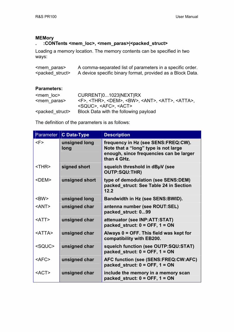
R&S PR100 User Manual
MEMory . :CONTents <mem_loc>, <mem_paras>|<packed_struct> Loading a memory location. The memory contents can be specified in two ways: <mem_paras> A comma-separated list of parameters in a specific order. <packed_struct> A device specific binary format, provided as a Block Data. Parameters: <mem_loc> CURRENT|0...1023|NEXT|RX <mem_paras> <F>, <THR>, <DEM>, <BW>, <ANT>, <ATT>, <ATTA>,
<SQUC>, <AFC>, <ACT> <packed_struct> Block Data with the following payload The definition of the parameters is as follows: Parameter C Data-Type Description <F> unsigned long
long frequency in Hz (see SENS:FREQ:CW). Note that a “long” type is not large enough, since frequencies can be larger than 4 GHz.
<THR> signed short squelch threshold in dBµV (see OUTP:SQU:THR)
<DEM> unsigned short type of demodulation (see SENS:DEM) packed_struct: See Table 24 in Section 12.2
<BW> unsigned long Bandwidth in Hz (see SENS:BWID). <ANT> unsigned char antenna number (see ROUT:SEL)
packed_struct: 0...99 <ATT> unsigned char attenuator (see INP:ATT:STAT)
packed_struct: 0 = OFF, 1 = ON <ATTA> unsigned char Always 0 = OFF. This field was kept for
compatibility with EB200. <SQUC> unsigned char squelch function (see OUTP:SQU:STAT)
packed_struct: 0 = OFF, 1 = ON <AFC> unsigned char AFC function (see (SENS:FREQ:CW:AFC)
packed_struct: 0 = OFF, 1 = ON <ACT> unsigned char include the memory in a memory scan
packed_struct: 0 = OFF, 1 = ON

R&S PR100 User Manual
The block data is a structure that is defined as follows: 32-bit aligned 8-bit aligned 16-bit aligned 8-bit aligned <F> (8 bytes)
<THR> <DEM> <BW> <ANT> <ATT> <ATTA> <SQUC> <AFC> <ACT> Not used
Remark: The parameter <ACT> is ignored for the RX memory-location (current RX settings). However, it must be specified. When loading with a <packed_struct>, the byte order within the 2- and 4-byte elements is determined by the command FORMat:BORDer. Example: MEMory:CONTents 1,98.5 MHz,30,FM,300,10,OFF,OFF,ON,OFF,ON

R&S PR100 User Manual
MEMory . :CONTents? <mem_loc> Query of contents of memory location. Parameters: <mem_loc> CURRENT|0...1023|RX Result: Depending on the setting by the command FORMat:MEMory, either ASCII or binary data are output. See MEM:CONT command for the format specifications. Depending on the setting by the command FORMat:BORder, the data are either big- or little-endian. Remark: The parameter <ACT> is not defined for the RX location. However, it is output, so it should be ignored. When trying to read out an empty memory location, error -292 ("Referenced name does not exist") is generated. Example: MEMory:CONTents? 1 -> 98500000,30,FM,300,10,0,0,1,0,1
MEMory . :CONTents . . :MPAR <mem_loc>,<Boolean> Setting the memory location parameter <ACT> (MPAR = Memory PARameter). Parameters: <mem_loc> CURRENT|0...1023|NEXT <Boolean> include/exclude the memory in a memory scan: 0 = OFF, 1 = ON Example: MEMory:CONTents:MPAR 1, OFF
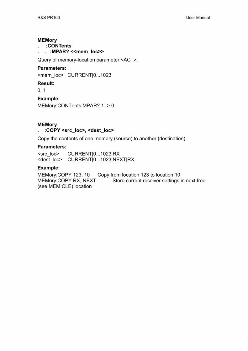
R&S PR100 User Manual
MEMory . :CONTents . . :MPAR? <<mem_loc>> Query of memory-location parameter <ACT>. Parameters: <mem_loc> CURRENT|0...1023 Result: 0, 1 Example: MEMory:CONTents:MPAR? 1 -> 0
MEMory . :COPY <src_loc>, <dest_loc> Copy the contents of one memory (source) to another (destination). Parameters: <src_loc> CURRENT|0...1023|RX <dest_loc> CURRENT|0...1023|NEXT|RX Example: MEMory:COPY 123, 10 Copy from location 123 to location 10 MEMory:COPY RX, NEXT Store current receiver settings in next free (see MEM:CLE) location
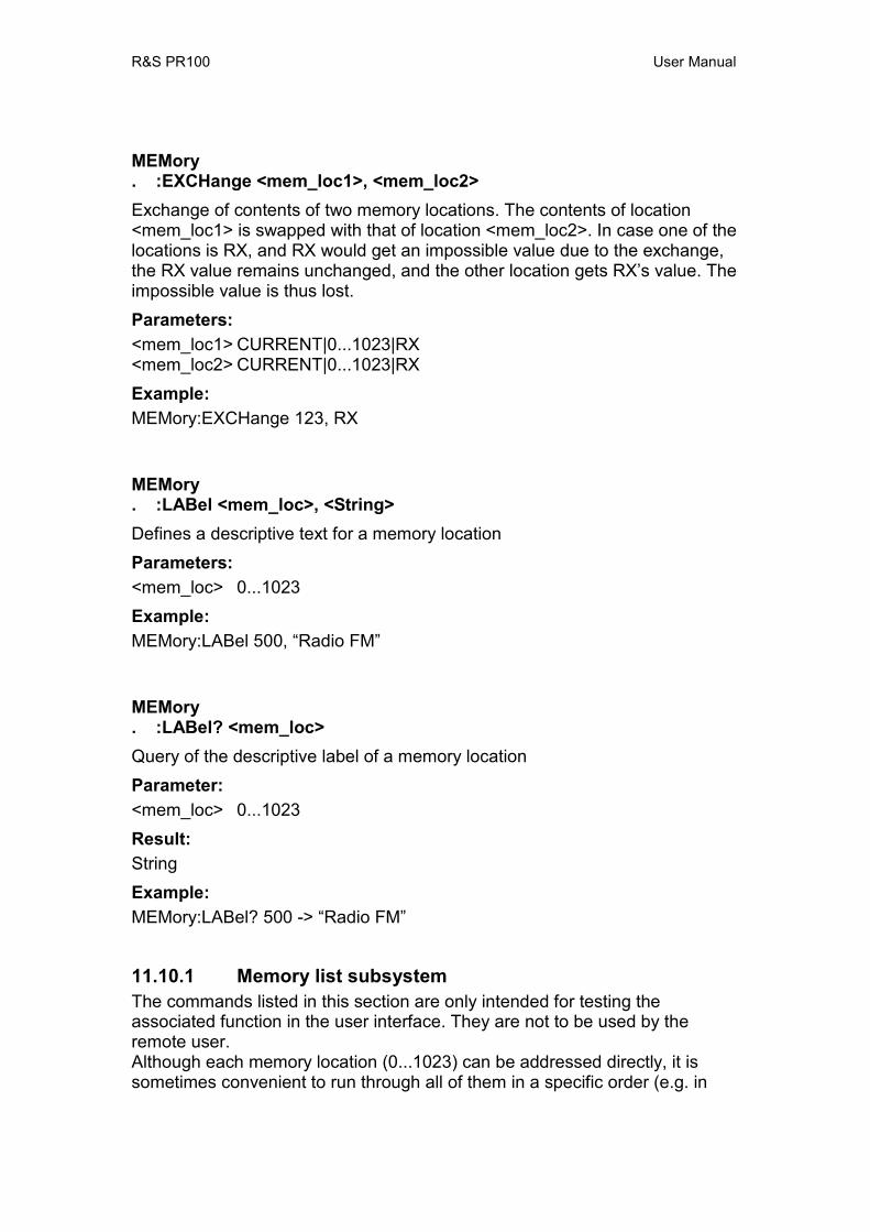
R&S PR100 User Manual
MEMory . :EXCHange <mem_loc1>, <mem_loc2> Exchange of contents of two memory locations. The contents of location <mem_loc1> is swapped with that of location <mem_loc2>. In case one of the locations is RX, and RX would get an impossible value due to the exchange, the RX value remains unchanged, and the other location gets RX’s value. The impossible value is thus lost. Parameters: <mem_loc1> CURRENT|0...1023|RX <mem_loc2> CURRENT|0...1023|RX Example: MEMory:EXCHange 123, RX
MEMory . :LABel <mem_loc>, <String> Defines a descriptive text for a memory location Parameters: <mem_loc> 0...1023 Example: MEMory:LABel 500, “Radio FM”
MEMory . :LABel? <mem_loc> Query of the descriptive label of a memory location Parameter: <mem_loc> 0...1023 Result: String Example: MEMory:LABel? 500 -> “Radio FM”
11.10.1 Memory list subsystem The commands listed in this section are only intended for testing the associated function in the user interface. They are not to be used by the remote user. Although each memory location (0...1023) can be addressed directly, it is sometimes convenient to run through all of them in a specific order (e.g. in

R&S PR100 User Manual
order of increasing frequency). To accomodate both an unordered and an ordered accesss of the memory locations, the memory list is used. The memory list has a number of items, one for each memory location. Each item links to a certain memory location. This way, the order in the memory locations can remain unchanged, while the list item allow to run through the memories in another order. See below an example for ordering on increasing frequency via the memory list: ... item 55 -> 25 (freq. 100000000) item 56 -> 6 (freq. 125000000) item 57 -> 2 (freq. 140000000) item 58 -> 800 (freq. 160000000) ... The memory scan (SENS:FREQ:MODE MSC) uses the memory list to run through all memory locations. The commands below under the MEMory:LIST subsystem control the order of the memory list.
MEMory . :LIST . . :CONTents? <index> Query to which memory location a list item has been linked Parameter: <index> integer number in the range [0,1023] Result: 0...1023 Example: MEMory:LIST:CONTents? 25 -> 60
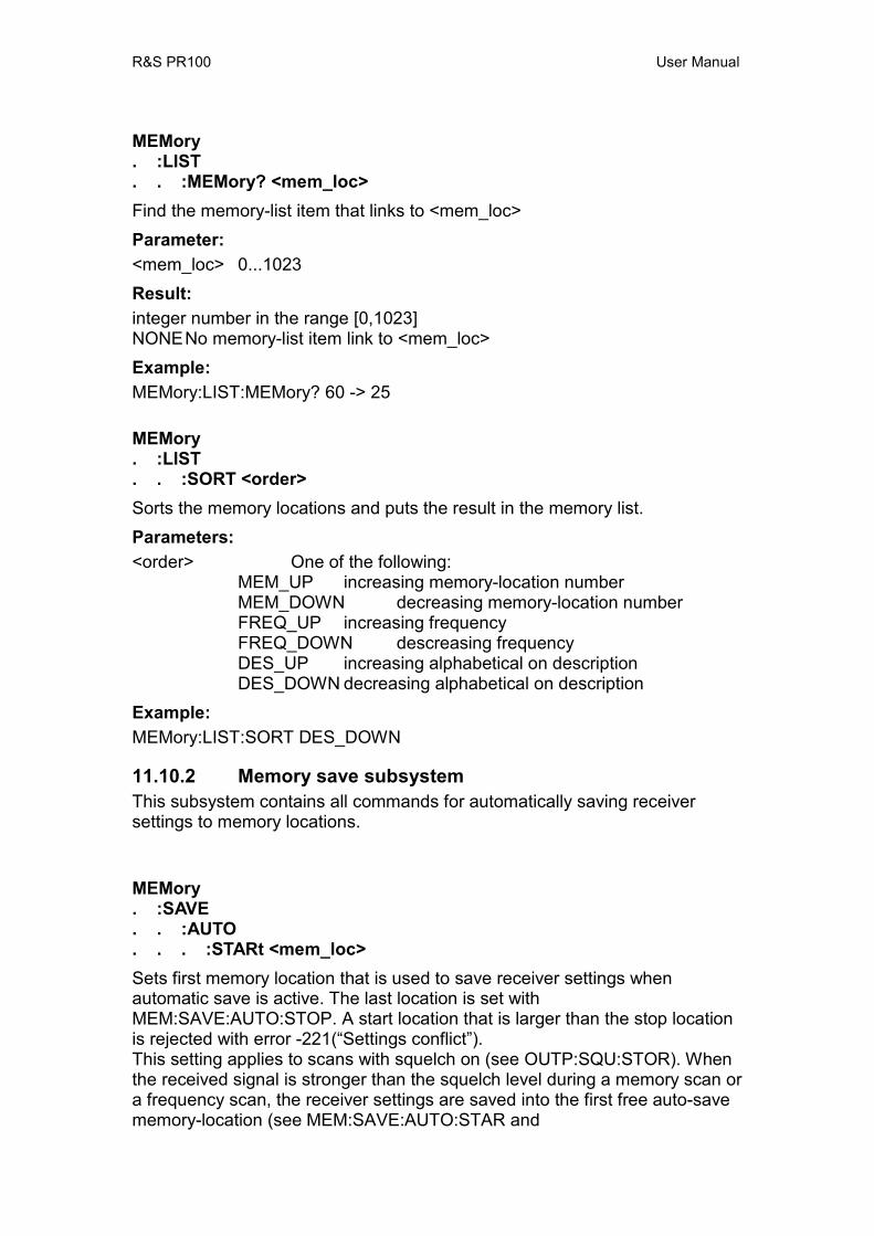
R&S PR100 User Manual
MEMory . :LIST . . :MEMory? <mem_loc> Find the memory-list item that links to <mem_loc> Parameter: <mem_loc> 0...1023 Result: integer number in the range [0,1023] NONE No memory-list item link to <mem_loc> Example: MEMory:LIST:MEMory? 60 -> 25
MEMory . :LIST . . :SORT <order> Sorts the memory locations and puts the result in the memory list. Parameters: <order> One of the following:
MEM_UP increasing memory-location number MEM_DOWN decreasing memory-location number FREQ_UP increasing frequency FREQ_DOWN descreasing frequency DES_UP increasing alphabetical on description DES_DOWN decreasing alphabetical on description
Example: MEMory:LIST:SORT DES_DOWN
11.10.2 Memory save subsystem This subsystem contains all commands for automatically saving receiver settings to memory locations.
MEMory . :SAVE . . :AUTO . . . :STARt <mem_loc> Sets first memory location that is used to save receiver settings when automatic save is active. The last location is set with MEM:SAVE:AUTO:STOP. A start location that is larger than the stop location is rejected with error -221(“Settings conflict”). This setting applies to scans with squelch on (see OUTP:SQU:STOR). When the received signal is stronger than the squelch level during a memory scan or a frequency scan, the receiver settings are saved into the first free auto-save memory-location (see MEM:SAVE:AUTO:STAR and

R&S PR100 User Manual
MEM:SAVE:AUTO:STOP). This setting is ignored in case the squelch is off (see OUTP:SQU:STAT). Parameters: <mem_loc> 0...1023 Example: MEMory:SAVE:AUTO:STARt 120
MEMory . :SAVE . . :AUTO . . . :STARt? Query of first memory location for auto save Parameter: none Result: 0...1023 Example: MEMory:SAVE:AUTO:STARt? -> 120
MEMory . :SAVE . . :AUTO . . . :STOP <mem_loc> Sets the last memory location that is used to save receiver settings when automatic save on squelch is active (see OUTP:SQU:STOR). The first location is set with MEM:SAVE:AUTO:STAR. A stop location that is smaller than the start location is rejected with error -221(“Settings conflict”). Parameters: <mem_loc> 0...1023 Example: MEMory:SAVE:AUTO:STOP 180
MEMory . :SAVE . . :AUTO . . . :STOP? Query of the last memory location used for auto save. Parameter: none
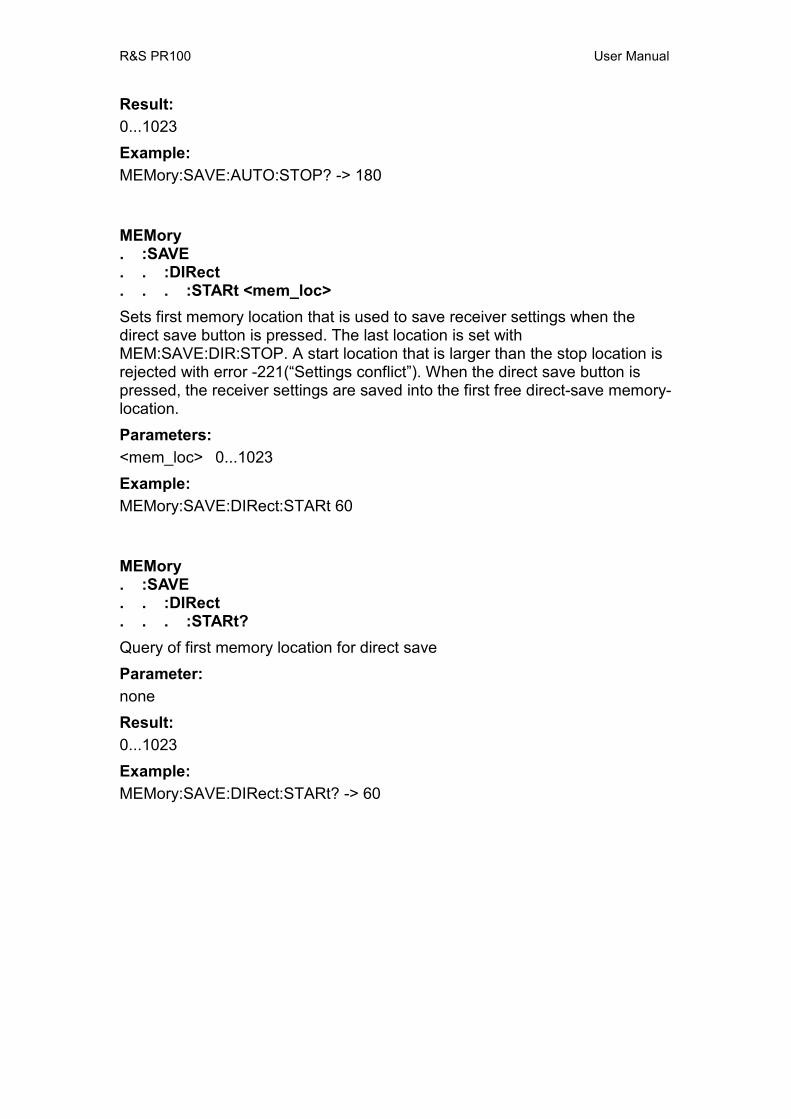
R&S PR100 User Manual
Result: 0...1023 Example: MEMory:SAVE:AUTO:STOP? -> 180
MEMory . :SAVE . . :DIRect . . . :STARt <mem_loc> Sets first memory location that is used to save receiver settings when the direct save button is pressed. The last location is set with MEM:SAVE:DIR:STOP. A start location that is larger than the stop location is rejected with error -221(“Settings conflict”). When the direct save button is pressed, the receiver settings are saved into the first free direct-save memory-location. Parameters: <mem_loc> 0...1023 Example: MEMory:SAVE:DIRect:STARt 60
MEMory . :SAVE . . :DIRect . . . :STARt? Query of first memory location for direct save Parameter: none Result: 0...1023 Example: MEMory:SAVE:DIRect:STARt? -> 60
R&S PR100 User Manual
MEMory . :SAVE . . :DIRect . . . :STOP <mem_loc> Sets the last memory location that is used to save receiver settings when the direct save button is pressed. The first location is set with MEM:SAVE:DIR:STAR. A stop location that is smaller than the start location is rejected with error -221(“Settings conflict”). Parameters: <mem_loc> 0...1023 Example: MEMory:SAVE:DIRect:STOP 120
MEMory . :SAVE . . :DIRect . . . :STOP? Query of last memory location used for direct save Parameter: none Result: 0...1023 Example: MEMory:SAVE:DIRect:STOP? -> 120
11.11 MMEMory subsystem This subsystem contains all commands that act on the mass storage of the MR, e.g. SD-Card.
MMEMory . :CATalog? List the files in the current directory of the mass storage device. Parameter: none Result: <used_storage>, <available_storage> , <file_entry> <file_entry> = <file_name>, <file_type>, <file_size>, <file_date>, <file_time> <used_storage> used storage in bytes <available_storage> available storage in bytes

R&S PR100 User Manual
<file_name> string of characters <file_type> the file extension (part after the last dot in the name) <file_size> size of the file in bytes <file_date> date of file in format <day>, <month>, <year> The format in NOT influenced by the DISP:DATE:FORM command. <file_time> time of file in format <hours>, <minutes>, <seconds> Example: MMEMory:CATalog? -> 3000, 120000000, file 1, txt, 1000, 14-12-2006, 19:05:03, file 2, log, 2000, 15-11-2005, 21:07:08
R&S PR100 User Manual
MMEMory . :CATalog . . :DIRectories? List the directories in the current directory of the mass storage device. Parameter: none Result: <used_storage>, <available_storage> , <file_entry> <file_entry> = <file_name>, <file_type>, <file_size> <used_storage> used storage in bytes <available_storage> available storage in bytes <file_name> string of characters <file_date> date of file in format <day>, <month>, <year> The format in NOT influenced by the DISP:DATE:FORM command. <file_time> time of file in format <hours>, <minutes>, <seconds> Example: MMEMory:CATalog? -> 3000, 120000000, directory 1 ,1000, 14-12-2006, 19:05:03, directory 2 ,2000, 15-11-2005, 21:07:08
R&S PR100 User Manual
MMEMory . :CDIRectory <folder_name> Change the default (current) folder (directory) to the specified one. The default folder is used for all other MMEMory commands and queries. In case the folder does not exist, an error is generated: .-292, “Referenced name does not exist” Parameters: <folder_name> String of characters (comma not allowed) Example: MMEMory:CDIRectory “SomeFolder”
MMEMory . : CDIRectory? Returns the default (current) folder (directory). Parameters: None Result: <folder_name> String of characters Example: MMEMory:CDIRectory? -> “SomeFolder”
MMEMory . :COPY <src_name>, <dest_name> Copies the file or folder <src_name> to <dest_name>. In case <src_name> does not exist in the current folder, an error is generated: .-292, “Referenced name does not exist”. In case <dest_name> already exists in the current folder, an error is generated: .-293, “Referenced name already exists”. Parameters: <src_name> source file/folder: String of characters (comma not allowed) <dest_name> destination file/folder: String of characters (comma not allowed) Example: MMEMory:COPY “file1”, “file3”

R&S PR100 User Manual
MMEMory . :DATA <file_name>, <block_data> Creates a new file, or overwrites an existing one, with the name <file_name>, and fills it with the binary data in <block_data> Parameters: <file_name> file: String of characters (comma not allowed) <block_data> block data Example: MMEMory:DATA “test.txt”, #15hello
MMEMory . : DATA? <file_name> Outputs the contents of the file <file_name> as block data. In case <file_name> does not exist, an error is generated: .-292, “Referenced name does not exist”. Parameters: <file_name> file: String of characters (comma not allowed) Result: <block_data> of file contents Example: MMEMory:DATA? “test.txt” -> #15hello
MMEMory . :DELete < name> Removes the file <name> from the current folder of the mass storage device. In case <name> does not exist, an error is generated: .-292, “Referenced name does not exist”. Parameters: <name> String of characters (comma not allowed) Example: MMEMory:DELete “file”
R&S PR100 User Manual
MMEMory . :FILE <file_name>, <block_data> Alias of MMEM:DATA Remark: See MMEM:DATA
MMEMory . : FILE? <file_name> Alias of MMEM:DATA? Remark: See MMEM:DATA?
MMEMory . :FILE . . :DATE <file_name>, <year>, <month>, <day> Sets the modification date of an existing file. In case <file_name> does not exist, an error is generated: .-292, “Referenced name does not exist”. Parameters: <file_name> file: String of characters (comma not allowed) <block_data> block data <year> integer number in the range [2000-2099] <month> integer number in the range [1,12] (1 = January, 12 = December) <day> integer number in the range [1,31] Error: In case the date is invalid, an execution error -200,"Execution error" is generated. Example: MMEMory:FILE:DATE “test.txt”, 2006, 12, 14
R&S PR100 User Manual
MMEMory . : FILE . . :DATE? <file_name> Outputs the modification date of an existing file. In case <file_name> does not exist, an error is generated: .-292, “Referenced name does not exist”. Parameters: <file_name> file: String of characters (comma not allowed) Result: <year>, <month>, <day> (See MMEM:FILE:DATE) Example: MMEMory:FILE:DATE? “test.txt” -> 2006, 14, 12, 14
MMEMory . :FILE . . :TIME <file_name>, <hours>, <minutes>, <seconds> Sets the modification time of an existing file. In case <file_name> does not exist, an error is generated: .-292, “Referenced name does not exist”. Parameters: <file_name> file: String of characters (comma not allowed) <block_data> block data <hours> integer number in the range [0:23] <minutes> integer number in the range [0:59] <seconds> any number in the range [0:60]
The seconds are specified by a real number that is rounded toward the resolution of the device’s internal clock accuracy. The number 60 is allowed here, because rounding can yield a number larger than 59.5.
Error: In case the time is invalid, an execution error -200,"Execution error" is generated. Example: MMEMory:FILE:TIME “test.txt”, 22, 23, 24.09
R&S PR100 User Manual
MMEMory . : FILE . . :TIME? <file_name> Outputs the modification time of an existing file. In case <file_name> does not exist, an error is generated: .-292, “Referenced name does not exist”. Parameters: <file_name> file: String of characters (comma not allowed) Result: <hours>, <minutes>, <seconds> (See MMEM:FILE:TIME) Example: MMEMory:FILE:TIME? “test.txt” -> 22, 23, 24.09
MMEMory . :INIT [<label>] Deletes all files and directories from the mass storage device. After that, it restores default directories and files that are needed for correct operation of the device, and assigns a label to the mass storage. Parameters: none The existing label for the mass storage is not changed <label> String of character for the new label for the mass storage Example: MMEMory:INIT “Measurements”
MMEMory . :MDIRectory <folder_name> Creates a new folder <folder_name> in the current folder of the mass storage device. In case <folder_name> already exists in the current folder, an error is generated: .-293, “Referenced name already exists”. Parameters: <folder_name> String of characters (comma not allowed) Example: MMEMory:MDIRectory “SomeFolder”
MMEMory . :MOVE <src_name>, <dest_name> Renames the file or folder <src_name> into <dest_name. In case <name> does not exist in the current folder, an error is generated: .-292, “Referenced name does not exist”. In case <dest_name> already exists in the current folder, an error is generated: .-293, “Referenced name already exists”.
R&S PR100 User Manual
Parameters: <src_name> source file/folder: String of characters (comma not allowed) <dest_name> destination file/folder: String of characters (comma not allowed) Example: MMEMory:MOVE “file1”, “file2”
MMEMory . :RDIRectory <folder_name> Removes an existing folder <folder_name> in the current folder of the mass storage device. In case <name> does not exist in the current folder, an error is generated: .-292, “Referenced name does not exist”. Parameters: <folder_name> String of characters (comma not allowed) Example: MMEMory:MDIRectory “SomeFolder”
11.12 OUTPut subsystem OUTPut . :AUX . . :AUTO <Boolean> Sets whether the auxilary bits on AUX1 are automatically determined by the selected antenna or if they are manually affected by using the BITAux or BYTAux commands. *Parameters: ON Automatic OFF Manual Example: OUTPut:AUX:AUTO ON OUTPut . :AUX . . :AUTO? Queries whether the auxilary bits on AUX1 are automatically determined by the selected antenna or if they are manually affected by using the BITAux or BYTAux commands.
R&S PR100 User Manual
*Parameters: 0 Manual 1 Automatic Example: OUTPut:AUX:AUTO? -> 1
OUTPut . :BITaux[<numeric_suffix>] . . [:STATe] <Boolean> Sets the antenna-selection bits. In case another antenna is chosen via ROUT:SEL, these settings are changed again. <numeric_suffix>
1 bit 1 corresponds to antenna-bit 1 2 bit 2 corresponds to antenna-bit 2
*Parameters: ON Bit set to 1 OFF Bit set to 0 Example: OUTPut:BITaux2 ON OUTPut . :BITaux[<numeric_suffix>] . . [:STATe] ? Query of the antenna-selection bits. Result: 0 OFF 1 ON Parameters: none Example: OUTPut:BITaux2? -> 1

R&S PR100 User Manual
OUTPut . :BYTaux . . [:STATe] <numeric_value> Sets all antenna-selection bits with a single command. Parameters: <numeric_value> value of the antenna-selection bits (0 to 3, #H00 to #H03, #B0 to #B11, #Q0 to #Q3) *RST state: 0Example: OUTPut : BYTAux 7 OUTPut . :BYTaux . . [:STATe]? Query of all antenna-selection bits by a single byte command. Parameters: none Result: The output format depends on the FORMat:SREG command. Example: OUTPut : BYTAux? -> 3

R&S PR100 User Manual
OUTPut . :IF . . [:STATe] <Boolean> Sets the IF output state. If it is ON, the MR activates a separate output on which it puts the received-signal, that has been mixed downwards to the IF frequency and bandwidth limited to 10 MHz. *Parameters: ON Bit set to 1 OFF Bit set to 0 Example: OUTPut:IF:STATe ON OUTPut . :IF . . [:STATe] ? Query of IF output state Result: 0 OFF 1 ON Parameters: none Example: OUTPut:IF:STATe? -> 1
R&S PR100 User Manual
OUTPut . :SQUelch . . :CONTrol MEMory|NONE When retrieving RX settings from a memory location, the squelch state and value are also retrieved when OUTP:SQU:CONT is set to MEMory. Otherwise, the squelch state and value are not retrieved and their settings remain unchanged. Parameters: MEMory squelch state and squelch value are read out of the memory locations NONE squelch state and squelch value are not read out of the memory locations Example: OUTPut:SQUelch:CONTrol MEMory OUTPut . :SQUelch . . :CONTrol? Query of the source of squelch setting when reading memory locations. Parameters: none Result: MEM, NONE Example: OUTPut:SQUelch:CONTrol? -> MEM

R&S PR100 User Manual
OUTPut . :SQUelch . . [:STATe] <Boolean> Switch on/off of squelch. Parameters: ON squelch on OFF squelch off Example: OUTPut:SQUelch ON OUTPut . :SQUelch . . [:STATe]? Query of squelch setting. Parameters: none Result: 0 OFF 1 ON State: OUTPut:SQUelch? -> 1
R&S PR100 User Manual
OUTPut . :SQUelch . . :THReshold . . . [:UPPer] <numeric_value>|UP|DOWN|MINimum|MAXimum Setting of squelch threshold. Parameters: <numeric_value> squelch threshold in dBµVUP|DOWN increase|decrease of squelch threshold by the value set
with the command OUTPut:SQUelch:THReshold[:UPPer]:STEP[:INCRement].
MINimum|MAXimum setting the lowest/highest squelch threshold Example: OUTPut:SQUelch:THReshold 35 dBuV OUTPut . :SQUelch . . :THReshold . . . [:UPPer]? [MINimum|MAXimum] Query of squelch threshold. Parameters: none query of current squelch threshold MINimum|MAXimum query of lowest/highest squelch threshold Result: squelch threshold value in dBµVExample: OUTPut:SQUelch:THReshold? -> 35
R&S PR100 User Manual
OUTPut . :SQUelch . . :THReshold . . . [:UPPer] . . . . :STEP . . . . . [:INCRement] <numeric_value>|MINimum|MAXimum Setting the stepwidth for the command OUTP:SQU:THR[:UPP] UP|DOWN Parameters: <numeric_value> stepwidth of squelch threshold in dBµVMINimum|MAXimum setting the smallest|largest stepwidth Example: OUTP:SQU:THR:STEP 10 dBuV OUTPut . :SQUelch . . :THReshold . . . [:UPPer] . . . . :STEP . . . . . [:INCRement]? [MINimum|MAXimum] Query of squelch stepwidth Parameters: none query of currently set stepwidth MINimum|MAXimum query of smallest|largest stepwidth Result: Stepwidth of squelch threshold in dBµVExample: OUTP:SQU:THR:STEP? -> 10
R&S PR100 User Manual
OUTPut . :TONE . . :CONTrol ONLY|WITHaf It can be selected whether, in the TONE mode, only the level tone or also the AF is output via the audio channel. Parameters: WITHaf level tone and AF is output. ONLY only level tone is output. Example: OUTPut:TONE:CONTrol ONLY OUTPut . :TONE . . :CONTrol? Query of whether, in the TONE mode, only the level tone or also the AF is output via the audio channel. Parameters: none Result: ONLY, WITH Example: OUTPut:TONE:CONTrol? -> ONLY
R&S PR100 User Manual
OUTPut . :TONE . . :GAIN <numeric_value>|MINimum|MAXimum|UP|DOWN Setting of tone gain. See also OUTP:TONE:THR for a description of its use. Parameters: <numeric_value> Tone gain in Octave/ <numeric_value>dB MINimum|MAXimum setting the lowest/highest tone gain Remark: The range can be set in discrete steps. Intermediate values are therefore rounded to the nearest discrete value. Example: OUTPut:TONE:GAIN 20 OUTPut . :TONE . . :GAIN? [MINimum|MAXimum] Query of tone gain Parameters: none query of current tone gain MINimum|MAXimum query of lowest/highest tone gain Result: Tone gain in Octave/ <numeric_value>dB Example: OUTPut:TONE:GAIN? -> 20
R&S PR100 User Manual
OUTPut . :TONE . . [:STATe] <Boolean> Switch on/off of level tone function. When on, a tone is output depending on the level magnitude. Parameters: ON level tone on OFF level tone off Example: OUTPut:TONE ON OUTPut . :TONE . . [:STATe]? Query of the TONE mode. Parameters: none Result: 0 OFF 1 ON Example: OUTPut:TONE? -> 1
R&S PR100 User Manual
OUTPut . :TONE . . :THReshold <numeric_value>|UP|DOWN|MINimum|MAXimum Setting the tone-level reference-threshold. It determines what signal level is to be output as 400 Hz: e.g. usually this is set to 0 dBµV, which means that a signal of that strength produces a tone of 400 Hz. Together with the settings OUTP:TONE:GAIN, this setting determines the frequency of the tone for each received signal level. Parameters: <numeric_value> level tone reference threshold in dBµVUP|DOWN increase|decrease of level tone reference threshold by the value set in the
OUTPut:TONE:THReshold:STEP[:INCRement] command.
MINimum|MAXimum setting the lowest/highest level tone reference threshold Example: OUTPut:TONE:THReshold 35 dBuV OUTPut . :TONE . . :THReshold? [MINimum|MAXimum] Query of level tone reference threshold. Parameters: none query of current level tone reference threshold MINimum|MAXimum query of lowest/highest level tone reference threshold Result: Level tone reference threshold in dBµVExample: OUTPut:TONE:THReshold? MIN -> 6
R&S PR100 User Manual
OUTPut . :TONE . . :THReshold . . . :STEP . . . . [:INCRement] <numeric_value>|MINimum|MAXimum Setting the stepwidth for the OUTP:TONE:THR UP|DOWN command. Parameters: <numeric_value> stepwidth for level tone reference threshold in dBµVMINimum|MAXimum setting the smallest/largest stepwidth Example: OUTP:TONE:THR:STEP 10 dBµV
OUTPut . :TONE . . :THReshold . . . :STEP . . . . [:INCRement]? [MINimum|MAXimum] Query of tone-threshold stepwidth. Parameters: none query of currently set stepwidth MINimum|MAXimum query of smallest/largest stepwidth Result: Stepwidth for level tone reference threshold in dBµVExample: OUTP:TONE:THR:STEP? -> 10
R&S PR100 User Manual
11.13 Program preset subsystem This sub-system allows saving of all settings of the device as a “preset”. The settings saved into a preset can be recalled, after which all the settings in the preset are restored. The commands below allow for saving to and recalling from presets. PROGram . : PRESet . . :CATalog? Query of available presets Parameters: none Remark: Beware that user defined preset names, using PROG:PRES:DEF <name>, are not visible in the User Interface of the instrument. The User Interface always display User Preset <nr> regardless the entered name via SCPI. The name display User Preset <nr> is used when the user stores a preset via the User Interface. Result: comma separated list of preset-names. Example: PROG:PRES:CAT? -> “User Preset 1”, “User Preset 2”

R&S PR100 User Manual
PROGram . : PRESet . . :DEFine <name> Defines the name <name> for all current settings of the device. Parameters: <name> String of characters enclosed in double quotes Remark: Beware that user defined preset names, using PROG:PRES:DEF <name>, are not visible in the User Interface of the instrument. The User Interface always display User Preset <nr> regardless the entered name via SCPI. The name display User Preset <nr> is used when the user stores a preset via the User Interface. The name parameters has a limit of 20 characters. Each name in the list should be unique. Error: Example: PROG:PRES:DEFine “User Preset 1”
R&S PR100 User Manual
PROGram . : PRESet . . :DELete <name> Deletes a preset with the name <name>. Parameters: <name> String of characters enclosed in double quotes Error: -292 Referenced name, preset, does not exist. Example: PROG:PRES:DELete “User Preset 1” PROGram . : PRESet . . :DELete . . . :ALL Deletes all saved presets Parameters: none Example: PROG:PRES:DELete:ALL

R&S PR100 User Manual
PROGram . : PRESet . . :SELect <name> Recalls all settings of a preset with the name <name>, and restores those settings in the device. When a preset with the specified name is not present, the error -292, “Referenced name does not exist” is generated. Parameters: <name> String of characters enclosed in double quotes Example: PROG:PRES:SELect “User Preset 1”
11.14 SENSe Subsystem
[SENSe] . :BANDwidth|BWIDth . . [:RESolution] <numeric_value>|UP|DOWN|MINimum|MAXimum Selection of bandwidth of demodulation path. Only certain bandwidths are allowed. If a number is specified, the smallest bandwidth that is still larger is selected. Parameters: <numeric_value> bandwidth in Hz UP|DOWN to next|previous bandwidth MINimum|MAXimum setting the narrowest|widest bandwidth Example: BANDwidth 2.4 kHz
[SENSe] . :BANDwidth|BWIDth . . [:RESolution]? [MINimum|MAXimum] Query of current IF bandwidth. Parameters: none query of current bandwidth MINimum|MAXimum query of narrowest|widest bandwidth Result: bandwidth in Hz Example: BANDwidth? -> 2400
R&S PR100 User Manual
[SENSe] . :CORRection . . :ANTenna ACTive|PASSive Sets the mode of the selected antenna. Parameters: ACTive For active (= amplifying) antennas PASSive For passive (= non amplifying) antennas Example: SENSe:CORRection:ANTenna ACT
[SENSe] . :CORRection . . :ANTenna? Query of antenna mode Parameters: none Result: ACT, PASS Example: SENSe:CORRection:ANTenna? -> ACT
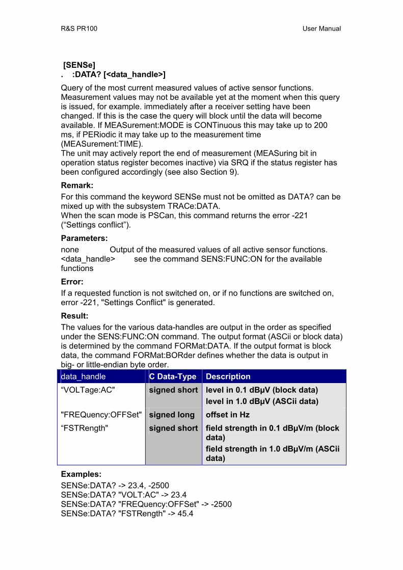
R&S PR100 User Manual
[SENSe] . :DATA? [<data_handle>] Query of the most current measured values of active sensor functions. Measurement values may not be available yet at the moment when this query is issued, for example. immediately after a receiver setting have been changed. If this is the case the query will block until the data will become available. If MEASurement:MODE is CONTinuous this may take up to 200 ms, if PERiodic it may take up to the measurement time (MEASurement:TIME). The unit may actively report the end of measurement (MEASuring bit in operation status register becomes inactive) via SRQ if the status register has been configured accordingly (see also Section 9). Remark: For this command the keyword SENSe must not be omitted as DATA? can be mixed up with the subsystem TRACe:DATA. When the scan mode is PSCan, this command returns the error -221 (“Settings conflict”). Parameters: none Output of the measured values of all active sensor functions. <data_handle> see the command SENS:FUNC:ON for the available functions Error: If a requested function is not switched on, or if no functions are switched on, error -221, "Settings Conflict" is generated. Result: The values for the various data-handles are output in the order as specified under the SENS:FUNC:ON command. The output format (ASCii or block data) is determined by the command FORMat:DATA. If the output format is block data, the command FORMat:BORder defines whether the data is output in big- or little-endian byte order. data_handle C Data-Type Description “VOLTage:AC" signed short level in 0.1 dBµV (block data)
level in 1.0 dBµV (ASCii data) "FREQuency:OFFSet" signed long offset in Hz “FSTRength" signed short field strength in 0.1 dBµV/m (block
data) field strength in 1.0 dBµV/m (ASCii data)
Examples: SENSe:DATA? -> 23.4, -2500 SENSe:DATA? "VOLT:AC" -> 23.4 SENSe:DATA? "FREQuency:OFFSet" -> -2500 SENSe:DATA? "FSTRength" -> 45.4
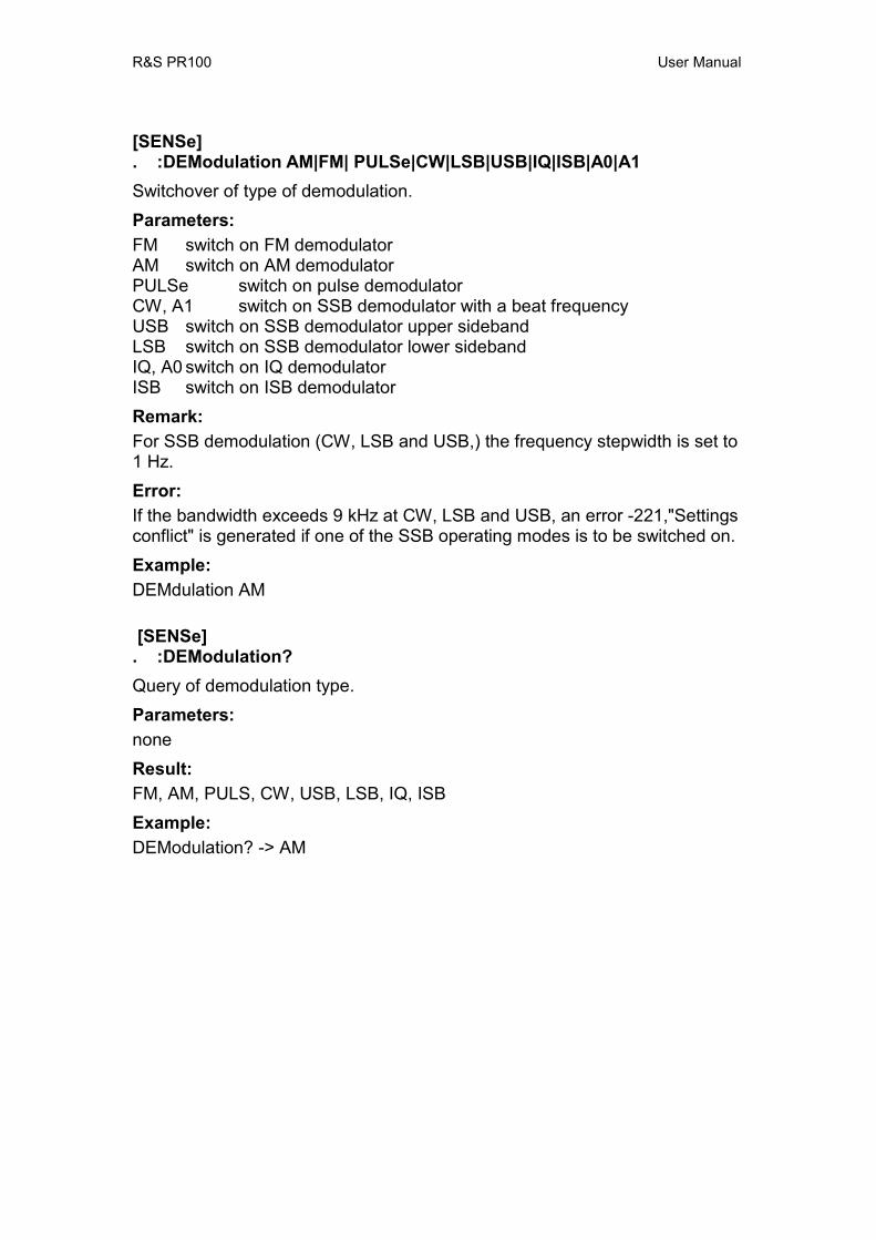
R&S PR100 User Manual
[SENSe] . :DEModulation AM|FM| PULSe|CW|LSB|USB|IQ|ISB|A0|A1 Switchover of type of demodulation. Parameters: FM switch on FM demodulator AM switch on AM demodulator PULSe switch on pulse demodulator CW, A1 switch on SSB demodulator with a beat frequency USB switch on SSB demodulator upper sideband LSB switch on SSB demodulator lower sideband IQ, A0 switch on IQ demodulator ISB switch on ISB demodulator Remark: For SSB demodulation (CW, LSB and USB,) the frequency stepwidth is set to 1 Hz. Error: If the bandwidth exceeds 9 kHz at CW, LSB and USB, an error -221,"Settings conflict" is generated if one of the SSB operating modes is to be switched on. Example: DEMdulation AM
[SENSe] . :DEModulation? Query of demodulation type. Parameters: none Result: FM, AM, PULS, CW, USB, LSB, IQ, ISB Example: DEModulation? -> AM
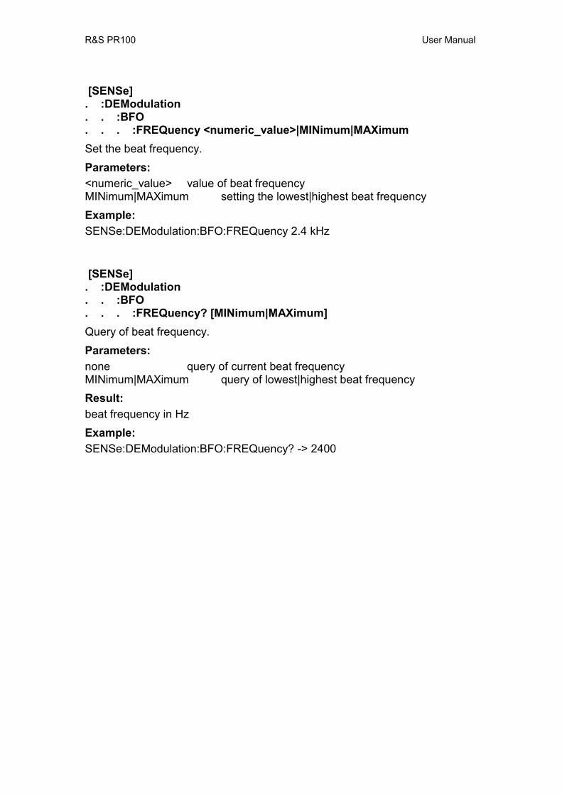
R&S PR100 User Manual
[SENSe] . :DEModulation . . :BFO . . . :FREQuency <numeric_value>|MINimum|MAXimum Set the beat frequency. Parameters: <numeric_value> value of beat frequency MINimum|MAXimum setting the lowest|highest beat frequency Example: SENSe:DEModulation:BFO:FREQuency 2.4 kHz
[SENSe] . :DEModulation . . :BFO . . . :FREQuency? [MINimum|MAXimum] Query of beat frequency. Parameters: none query of current beat frequency MINimum|MAXimum query of lowest|highest beat frequency Result: beat frequency in Hz Example: SENSe:DEModulation:BFO:FREQuency? -> 2400

R&S PR100 User Manual
[SENSe] . :DETector . . [:FUNCtion] AVG|FAST|PEAK|RMS Selecting the level-measuring process. Parameters: AVG measure the average value FAST measure the instantaneous value PEAK measure the maximum peak-value RMS measure the root-mean-square value Example: DETector RMS
[SENSe] . :DETector . . [FUNCtion]? Query of the level-measuring process. Parameters: none Result: AVG, FAST, PEAK, RMS Example: DETector? RMS
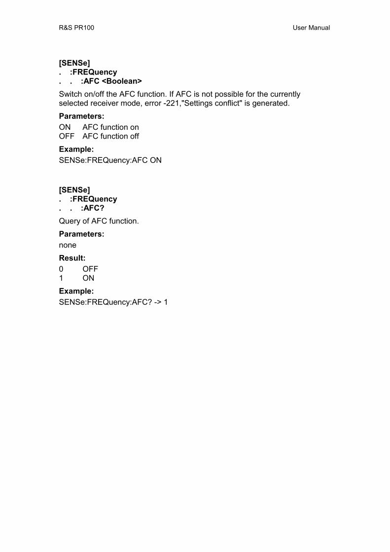
R&S PR100 User Manual
[SENSe] . :FREQuency . . :AFC <Boolean> Switch on/off the AFC function. If AFC is not possible for the currently selected receiver mode, error -221,"Settings conflict" is generated. Parameters: ON AFC function on OFF AFC function off Example: SENSe:FREQuency:AFC ON
[SENSe] . :FREQuency . . :AFC? Query of AFC function. Parameters: none Result: 0 OFF 1 ON Example: SENSe:FREQuency:AFC? -> 1

R&S PR100 User Manual
[SENSe] . :FREQuency . . :CONVersion . . . :THReshold <numeric_value>|MINimum|MAXimum Set the conversion threshold. This determines at which frequency the device switches from normal to direct path reception. During normal reception, the signal is modulated downward to an intermediate frequency. When the frequency drops below the conversion threshold, the downward modulation is skipped, hence the name “direct path” reception. Parameters: <numeric_value> value of conversion threshold MINimum|MAXimum setting the lowest|highest conversion threshold Example: SENSe:FREQuency:CONVersion:THReshold 27 MHz
[SENSe] . :FREQuency . . :CONVersion . . . :THReshold? [MINimum|MAXimum] Query of conversion threshold. Parameters: none query of current conversion threshold MINimum|MAXimum query of lowest|highest conversion threshold Result: conversion threshold in Hz Example: SENSe:FREQuency:CONVersion:THReshold? -> 27000000
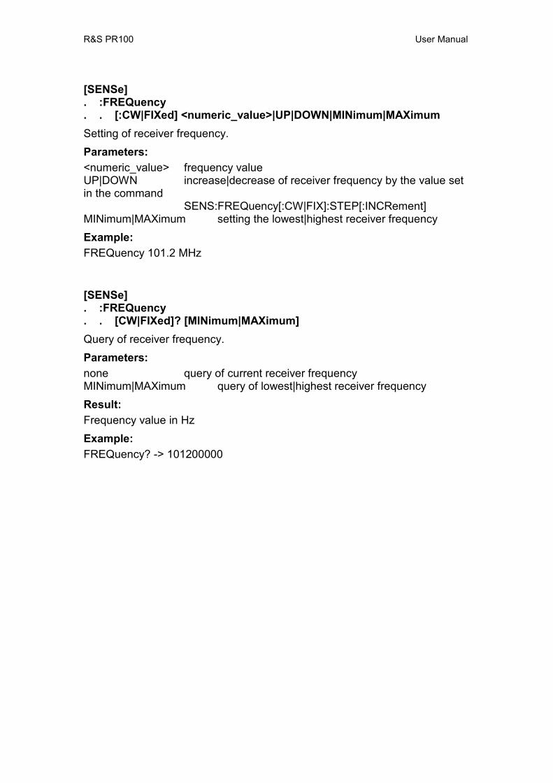
R&S PR100 User Manual
[SENSe] . :FREQuency . . [:CW|FIXed] <numeric_value>|UP|DOWN|MINimum|MAXimum Setting of receiver frequency. Parameters: <numeric_value> frequency value UP|DOWN increase|decrease of receiver frequency by the value set in the command
SENS:FREQuency[:CW|FIX]:STEP[:INCRement] MINimum|MAXimum setting the lowest|highest receiver frequency Example: FREQuency 101.2 MHz
[SENSe] . :FREQuency . . [CW|FIXed]? [MINimum|MAXimum] Query of receiver frequency. Parameters: none query of current receiver frequency MINimum|MAXimum query of lowest|highest receiver frequency Result: Frequency value in Hz Example: FREQuency? -> 101200000
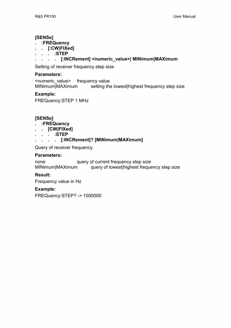
R&S PR100 User Manual
[SENSe] . :FREQuency . . [:CW|FIXed] . . . :STEP . . . . [:INCRement] <numeric_value>| MINimum|MAXimum Setting of receiver frequency.step size Parameters: <numeric_value> frequency value MINimum|MAXimum setting the lowest|highest frequency step size Example: FREQuency:STEP 1 MHz
[SENSe] . :FREQuency . . [CW|FIXed] . . . :STEP . . . . [:INCRement]? [MINimum|MAXimum] Query of receiver frequency. Parameters: none query of current frequency step size MINimum|MAXimum query of lowest|highest frequency step size Result: Frequency value in Hz Example: FREQuency:STEP? -> 1000000

R&S PR100 User Manual
[SENSe] . :FREQuency . . :MODE CW|FIXed|SWEep|MSCan|PSCan Changing the operating mode of the receiver. Parameters: CW | FIXed receiver monitors a frequency (CW and FIXed have equal meanings) SWEep receiver is in frequency-scan mode (see SENSe:SWEep) MSCan receiver is in memory-scan mode (see SENSe:MSCan) PSCan receiver is in panorama-scan mode (see SENSe:PSCan) Remark: The receiver stays on the CW frequency until it starts scanning. Example: FREQuency : MODE SWEep
[SENSe] . :FREQuency . . :MODE? Query of receiver operating mode. Parameters: none Result: CW, SWE, MSC, PSC Example: FREQuency:MODE? -> SWE
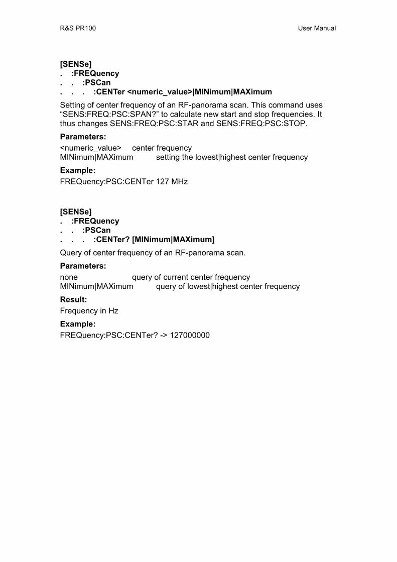
R&S PR100 User Manual
[SENSe] . :FREQuency . . :PSCan . . . :CENTer <numeric_value>|MINimum|MAXimum Setting of center frequency of an RF-panorama scan. This command uses “SENS:FREQ:PSC:SPAN?” to calculate new start and stop frequencies. It thus changes SENS:FREQ:PSC:STAR and SENS:FREQ:PSC:STOP. Parameters: <numeric_value> center frequency MINimum|MAXimum setting the lowest|highest center frequency Example: FREQuency:PSC:CENTer 127 MHz
[SENSe] . :FREQuency . . :PSCan . . . :CENTer? [MINimum|MAXimum] Query of center frequency of an RF-panorama scan. Parameters: none query of current center frequency MINimum|MAXimum query of lowest|highest center frequency Result: Frequency in Hz Example: FREQuency:PSC:CENTer? -> 127000000
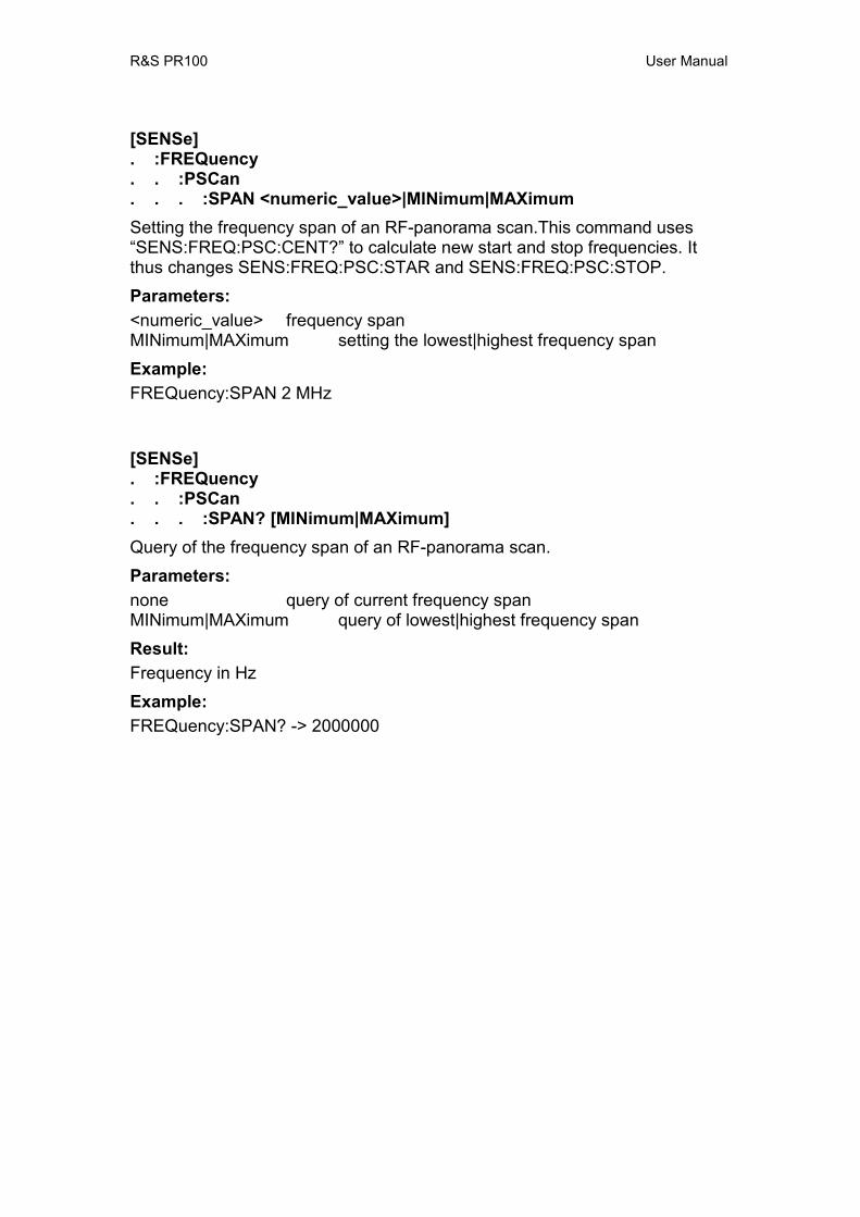
R&S PR100 User Manual
[SENSe] . :FREQuency . . :PSCan . . . :SPAN <numeric_value>|MINimum|MAXimum Setting the frequency span of an RF-panorama scan.This command uses “SENS:FREQ:PSC:CENT?” to calculate new start and stop frequencies. It thus changes SENS:FREQ:PSC:STAR and SENS:FREQ:PSC:STOP. Parameters: <numeric_value> frequency span MINimum|MAXimum setting the lowest|highest frequency span Example: FREQuency:SPAN 2 MHz
[SENSe] . :FREQuency . . :PSCan . . . :SPAN? [MINimum|MAXimum] Query of the frequency span of an RF-panorama scan. Parameters: none query of current frequency span MINimum|MAXimum query of lowest|highest frequency span Result: Frequency in Hz Example: FREQuency:SPAN? -> 2000000
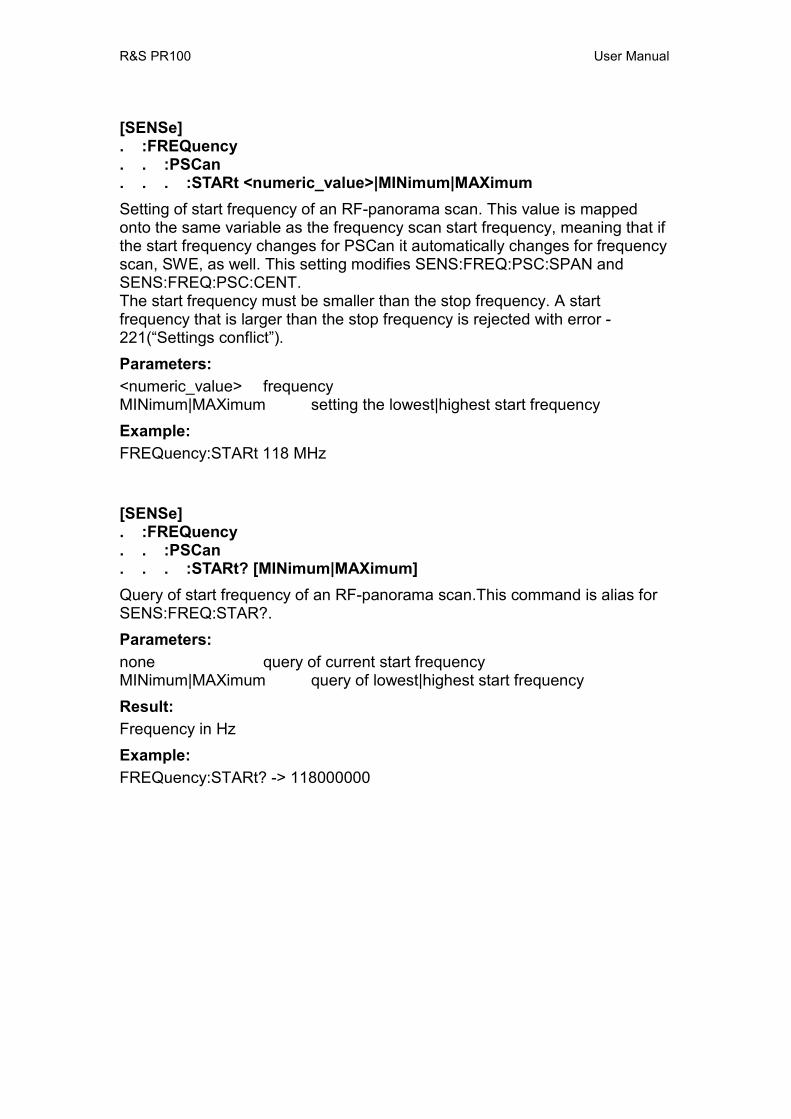
R&S PR100 User Manual
[SENSe] . :FREQuency . . :PSCan . . . :STARt <numeric_value>|MINimum|MAXimum Setting of start frequency of an RF-panorama scan. This value is mapped onto the same variable as the frequency scan start frequency, meaning that if the start frequency changes for PSCan it automatically changes for frequency scan, SWE, as well. This setting modifies SENS:FREQ:PSC:SPAN and SENS:FREQ:PSC:CENT. The start frequency must be smaller than the stop frequency. A start frequency that is larger than the stop frequency is rejected with error -221(“Settings conflict”). Parameters: <numeric_value> frequency MINimum|MAXimum setting the lowest|highest start frequency Example: FREQuency:STARt 118 MHz
[SENSe] . :FREQuency . . :PSCan . . . :STARt? [MINimum|MAXimum] Query of start frequency of an RF-panorama scan.This command is alias for SENS:FREQ:STAR?. Parameters: none query of current start frequency MINimum|MAXimum query of lowest|highest start frequency Result: Frequency in Hz Example: FREQuency:STARt? -> 118000000

R&S PR100 User Manual
[SENSe] . :FREQuency . . :PSCan . . . :STOP <numeric_value>|MINimum|MAXimum Setting the stop frequency of an RF-panorama scan. This value is mapped onto the same variable as the frequency scan stop frequency, meaning that if the stop frequency changes for PSCan it automatically changes for frequency scan, SWE, as well. This setting modifies SENS:FREQ:PSC:SPAN and SENS:FREQ:PSC:CENT. The start frequency must be smaller than the stop frequency. A start frequency that is larger than the stop frequency is rejected with error -221(“Settings conflict”). Parameters: <numeric_value> frequency MINimum|MAXimum setting the lowest|highest stop frequency Example: FREQuency:STOP 136 MHz
[SENSe] . :FREQuency . . :PSCan . . . :STOP? [MINimum|MAXimum] Query of a stop frequency of an RF-panorama scan. This command is alias for SENS:FREQ:STOP? Parameters: none query of current stop frequency MINimum|MAXimum query of lowest|highest stop frequency Result: Frequency in Hz Example: FREQuency:STOP? -> 136000000
R&S PR100 User Manual
[SENSe] . :FREQuency . . :SPAN <numeric_value>|UP|DOWN |MINimum|MAXimum Selection of frequency span for IF panorama. Only certain discrete ranges are offered. If an unavailable frequency range is entered it will be brought up to the next higher discrete range. Parameters: <numeric_value> frequency range UP|DOWN taking the range after|before the current bandwidth MINimum|MAXimum setting the minimum|maximum frequency range Example: FREQuency:SPAN 25 kHz
[SENSe] . :FREQuency . . :SPAN? [MINimum|MAXimum] Query of frequency span for IF panorama. Parameters: none query of current frequency range MINimum|MAXimum query of minimum|maximum frequency range Result: Frequency value Hz Example: FREQuency:SPAN? 25000
R&S PR100 User Manual
[SENSe] . :FREQuency . . :STARt <numeric_value>|MINimum|MAXimum Setting of start frequency of a frequency scan. This value is mapped onto the same variable as the PSCan start frequency, meaning that if the start frequency changes for frequency scan, SWE, it automatically changes for PSCan as well. The start frequency must be smaller than the stop frequency. A start frequency that is larger than the stop frequency is rejected with error -221(“Settings conflict”). Parameters: <numeric_value> frequency MINimum|MAXimum setting the lowest|highest start frequency Example: FREQuency:STARt 118 MHz
[SENSe] . :FREQuency . . :STARt? [MINimum|MAXimum] Query of start frequency of a frequency scan. Parameters: none query of current start frequency MINimum|MAXimum query of lowest|highest start frequency Result: Frequency in Hz Example: FREQuency:STARt? -> 118000000
R&S PR100 User Manual
[SENSe] . :FREQuency . . :STOP <numeric_value>|MINimum|MAXimum Setting the stop frequency of a frequency scan. This value is mapped onto the same variable as the PSCan stop frequency, meaning that if the stop frequency changes for frequency scan, SWE, it automatically changes for PSCan as well. The start frequency must be smaller than the stop frequency. A start frequency that is larger than the stop frequency is rejected with error -221(“Settings conflict”). Parameters: <numeric_value> frequency MINimum|MAXimum setting the lowest|highest stop frequency Example: FREQuency:STOP 136 MHz
[SENSe] . :FREQuency . . :STOP? [MINimum|MAXimum] Query of a stop frequency of a frequency scan. Parameters: none query of current stop frequency MINimum|MAXimum query of lowest|highest stop frequency Result: Frequency in Hz Example: FREQuency:STOP? -> 136000000
R&S PR100 User Manual
[SENSe] . :FUNCtion . . :CONCurrent <Boolean> Determines whether several sensor functions can at the same time be switched or not. If CONCurrent = OFF, the command SENSe:FUNCtion[:ON] has the effect of a 1-out-of-n selection (one is switched on, the previously activated is automatically switched off). If CONCurrent = ON, the command SENSe:FUNCtion[:ON] switches the corresponding function on, while all the other functions remain unchanged. If CONCurrent is switched from ON to OFF, the function "VOLTage:AC" is switched on and all other functions are switched off. Parameters: ON CONCurrent on OFF CONCurrent off *RST state: ON Example: FUNCtion:CONCurrent ON
[SENSe] . :FUNCtion . . :CONCurrent? Query of several sensor functions that, at the same time, can be switched or not. Parameters: none Result: 0 OFF 1 ON Example: FUNCtion:CONCurrent? -> 1
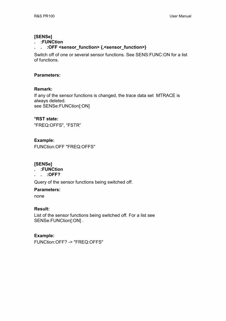
R&S PR100 User Manual
[SENSe] . :FUNCtion . . :OFF <sensor_function> ,<sensor_function> Switch off of one or several sensor functions. See SENS:FUNC:ON for a list of functions. Parameters: Remark: If any of the sensor functions is changed, the trace data set MTRACE is always deleted. see SENSe:FUNCtion[:ON] *RST state: "FREQ:OFFS", “FSTR” Example: FUNCtion:OFF "FREQ:OFFS"
[SENSe] . :FUNCtion . . :OFF? Query of the sensor functions being switched off. Parameters: none Result: List of the sensor functions being switched off. For a list see SENSe:FUNCtion[:ON] . Example: FUNCtion:OFF? -> "FREQ:OFFS"
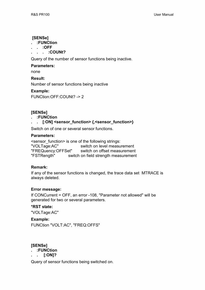
R&S PR100 User Manual
[SENSe] . :FUNCtion . . :OFF . . . :COUNt? Query of the number of sensor functions being inactive. Parameters: none Result: Number of sensor functions being inactive Example: FUNCtion:OFF:COUNt? -> 2
[SENSe] . :FUNCtion . . [:ON] <sensor_function> ,<sensor_function> Switch on of one or several sensor functions. Parameters: <sensor_function> is one of the following strings: "VOLTage:AC" switch on level measurement "FREQuency:OFFSet" switch on offset measurement "FSTRength" switch on field strength measurement Remark: If any of the sensor functions is changed, the trace data set MTRACE is always deleted. Error message: If CONCurrent = OFF, an error -108, "Parameter not allowed" will be generated for two or several parameters. *RST state: "VOLTage:AC" Example: FUNCtion "VOLT:AC", "FREQ:OFFS"
[SENSe] . :FUNCtion . . [:ON]? Query of sensor functions being switched on.

R&S PR100 User Manual
Parameters: none Result: List of sensor functions switched on. If no function is active, a zero string ("") is output. The list has a specific order: 1. "VOLT:AC" level measurement switched on 2. "FREQ:OFFS" offset measurement switched on 3. "FSTR" field strength measurement switched on Example: FUNCtion? -> "VOLT:AC", "FREQ:OFFS"
[SENSe] . :FUNCtion . . [:ON] . . . :COUNt? Query of the number of sensor functions being active. Parameters: none Result: Number of sensor functions being active Example: FUNCtion:Count? -> 2
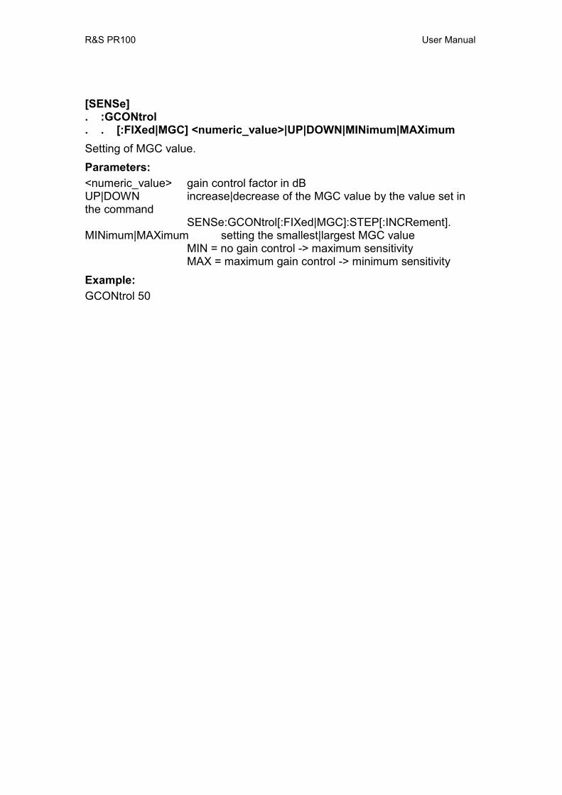
R&S PR100 User Manual
[SENSe] . :GCONtrol . . [:FIXed|MGC] <numeric_value>|UP|DOWN|MINimum|MAXimum Setting of MGC value. Parameters: <numeric_value> gain control factor in dB UP|DOWN increase|decrease of the MGC value by the value set in the command
SENSe:GCONtrol[:FIXed|MGC]:STEP[:INCRement]. MINimum|MAXimum setting the smallest|largest MGC value
MIN = no gain control -> maximum sensitivity MAX = maximum gain control -> minimum sensitivity
Example: GCONtrol 50

R&S PR100 User Manual
[SENSe] . :GCONtrol . . [:FIXed|MGC]? [MINimum|MAXimum] Query of the MGC value. Parameters: none query of current MGC value MINimum|MAXimum query of smallest|largest MGC value Result: Gain control Example: GCONtrol? -> 50
[SENSe] . :GCONtrol . . [:FIXed|MGC] . . . :STEP . . . . [:INCRement] <numeric_value>|MINimum|MAXimum Setting the stepwidth for the command SENSe:GCONtrol[:FIXed|MGC] UP|DOWN. Parameters: <numeric_value> MGC stepwidth MINimum|MAXimum smallest|largest stepwidth Example: GCONtrol:STEP 10
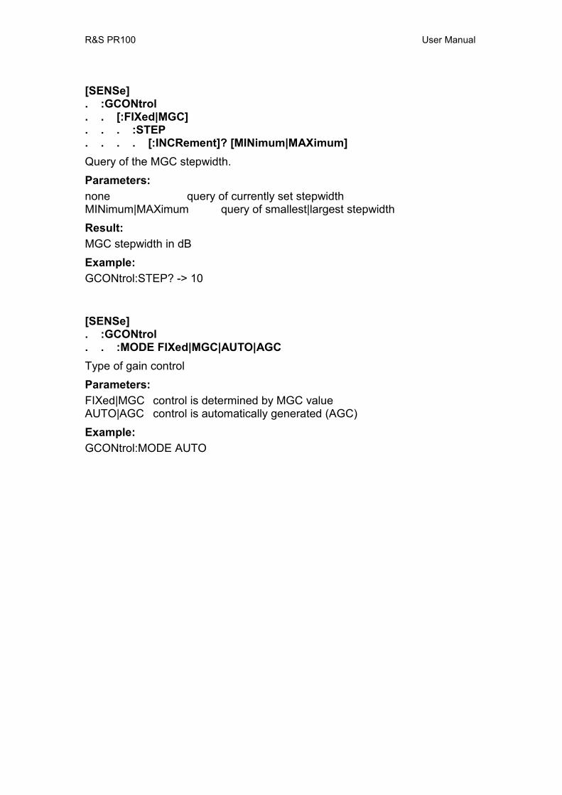
R&S PR100 User Manual
[SENSe] . :GCONtrol . . [:FIXed|MGC] . . . :STEP . . . . [:INCRement]? [MINimum|MAXimum] Query of the MGC stepwidth. Parameters: none query of currently set stepwidth MINimum|MAXimum query of smallest|largest stepwidth Result: MGC stepwidth in dB Example: GCONtrol:STEP? -> 10
[SENSe] . :GCONtrol . . :MODE FIXed|MGC|AUTO|AGC Type of gain control Parameters: FIXed|MGC control is determined by MGC value AUTO|AGC control is automatically generated (AGC) Example: GCONtrol:MODE AUTO
R&S PR100 User Manual
[SENSe] . :GCONtrol . . :MODE? Query of type of gain control. Parameters: none Result: FIX, AUTO Example: GCONtrol:MODE? -> AUTO
11.14.1 Sense Memory Scan subsystem MSC The MSCan system controls the memory-scan function of the device, provided the memory scan has been activated by SENSe:FREQuency:MODE MSCan. Each scan is started by INITiate[:IMMediate]. The memory locations are placed in the MEMory subsystem and are set for query during the scan.
[SENSe] . :MSCan . . :CHANnel <mem_loc>|UP|DOWN|NEXT Setting of current memory location. During the memory scan, this command is not permitted and generates error -200 , “Execution error” Parameters: <mem_loc> memory location in the range [0...1023] UP|DOWN the next or previous memory location NEXT the next free memory location is selected, starting from and including the current location. If the end of the memory list is reached without finding a free location, the search continues at the beginning of the list. If no free location is available an error -223 “Too much data” is generated Example: MSCan:CHANnel 357
[SENSe] . :MSCan . . :CHANnel? Output of current memory location. Parameters: none

R&S PR100 User Manual
Result: Index of current memory location. Example: MSCan:CHANnel? 357
R&S PR100 User Manual
[SENSe] . :MSCan . . :CONTrol . . . :OFF <control_function> ,<control_function Switches off one or more scan-control mechanisms. This value is mapped onto the same variable as the frequency scan control mechanism variable, meaning that a change affects both scan modes. Parameters: see SENSe:MSCan:CONTrol [:ON] *RST state after *RST, all control mechanisms are ON Example: MSCan:CONTrol:OFF "STOP:SIGN"
[SENSe] . :MSCan . . :CONTrol . . . :OFF? Query of scan-control mechanisms that are switched OFF. Parameters: none Result: A list of the scan-control mechanisms that are switched off is output. For strings see SENSe:MSCan:CONTrol[:ON]. Example: MSCan:CONTrol:OFF? -> "STOP:SIGN"
R&S PR100 User Manual
[SENSe] . :MSCan . . :CONTrol . . . :[ON] <control_function> ,<control_function> Command for switch-on of the 'STOP:SIGNal' function. When this function is off, the memory scan stops at each location with a signal for the dwell-time. When this function is on, the dwell-time is controlled by the presence of a signal stronger than the threshold level: During a memory-scan, the receiver moves from one memory location to another, loading the settings into the receiver. If a memory location has a signal that is stronger than the threshold level, the receiver stays on that memory location for a certain time, called dwell time. When the signal disappears during that dwell time, the receiver stays on the same location for a while, called hold time, to see if the signal re-appears. When either the hold-time or the dwell-time has elapsed, scanning continues. If the signal does re-appear, the receiver continues the dwell time again (the dwell-time never stopped), otherwise it moves to the next memory location. This value is mapped onto the same variable as the frequency scan control mechanism variable, meaning that a change affects both scan modes. Parameters: <control_function> is the following string: “STOP:SIGNal” switches the signal-controlled dwell time on *RST state: after *RST, all control mechanisms are on Example: MSCan:CONTrol “STOP:SIGN”

R&S PR100 User Manual
[SENSe] . :MSCan . . :CONTrol . . . [:ON]? Query of scan-control mechanism that is switched on. Parameters: none Result: A list of the scan-control mechanisms that are switched on is output. If nothing is switched on, a zero string ("") is output. The following strings can be expected: " " no mechanism switched on "STOP:SIGN" signal-controlled dwell-time is switched on Example: MSCan:CONTrol? -> "STOP:SIGN"
R&S PR100 User Manual
[SENSe] . :MSCan . . :COUNt <numeric_value>|MINimum|MAXimum|INFinity The number of MSCans to be done in response to the command “INIT:IMM”. Note that the scan mode must be MSCan. This value is mapped onto the same variable as the frequency scan and pscan count variable, meaning that a change affects all scan modes. Parameters: <numeric_value> number of scans MINimum|MAXimum minimum|maximum number INFinity infinite number Example: MSCan:COUNt 100
[SENSe] . :MSCan . . :COUNt? [MINimum|MAXimum] Query of number of MSCans. This command is an alias of SENS:SWE:COUN?. Parameters: none query of current number of scans MINimum|MAXimum query of minimum|maximum number of scans Result: Number of scans; 9.9E37 is output for an infinite number Example: MSCan:COUNt? -> 100
R&S PR100 User Manual
[SENSe] . :MSCan . . :DIRection UP|DOWN Sets scan direction. This value is mapped onto the same variable as the frequency scan direction variable, meaning that a change affects both scan modes. Parameters: UP scans in direction of ascending memory numbers DOWN scans in direction of descending memory numbers Example: MSCan:DIRection DOWN
[SENSe] . :MSCan . . :DIRection? Query of scan direction. This command is an alias of SENS:SWE:DIR?. Parameters: none Result: UP, DOWN Example: MSCan:DIRection? DOWN
R&S PR100 User Manual
[SENSe] . :MSCan . . :DWELl <numeric_value>|MINimum|MAXimum|INFinity Setting the dwell time. This value is mapped onto the same variable as the frequency scan dwell variable, meaning that a change affects both scan modes. Parameters: <numeric_value> dwell time in seconds MINimum|MAXimum lowest|highest dwell time INFinity infinite dwell time Remark: This command is used to set the dwell time per scan step, ie the time required by a step, if the squelch is switched off. Example: SWEep:DWEL 100 ms
[SENSe] . :MSCan . . :DWELl? [MINimum|MAXimum] Query of dwell time. This command is an alias of SENS:SWE:DWEL?. Parameters: none query of current dwell time MINimum|MAXimum query of lowest|highest dwell time Result: Dwell time in seconds; 9.9E37 is output for an infinite number Example: MSCan:DWEL? 0.10

R&S PR100 User Manual
[SENSe] . :MSCan . . :HOLD . . . :TIME <numeric_value>|MINimum|MAXimum Setting the hold time for a signal-controlled scan continuation. If the signal disappears during the dwell time, the hold time is started. After completion of the hold time, the scan is continued with the next frequency even if the dwell time has not yet been completed. If the signal exceeds the squelch threshold during the hold time, the hold time is reset and the end of the dwell time or the renewed disappearance of the signal is awaited. The hold time is only used if the control function "STOP:SIGNal" (see SENSe:MSCan:CONTrol) is switched on. Setting the time to 0 (zero) has the same effect as switching off the control function with SENS:MSC:CONT:OFF “STOP:SIGN”. This value is mapped onto the same variable as the frequency scan hold time variable, meaning that a change affects both scan modes. Parameters: <numeric_value> hold time in seconds MINimum|MAXimum lowest|highest hold time Example: SWEep:HOLD:TIME 100 ms
[SENSe] . :MSCan . . :HOLD . . . :TIME? [MINimum|MAXimum] Query of hold time. This command is an alias of SENS:SWE:HOLD:TIME?. Parameters: none query of current hold time MINimum|MAXimum query of lowest|highest hold time Result: Hold time in seconds Example: MSCan:HOLD:TIME? 0.10

R&S PR100 User Manual
[SENSe] . :MSCan . . :LIST . . . :STARt <numeric_value>|MINimum|MAXimum Sets the memory list item from which a memory scan starts. A start location that is larger than the stop location is rejected with error -221(“Settings conflict”). Parameters: <numeric_value> integer number in the range [0,1023] MINimum|MAXimum set lowest|highest start location Example: SENSe:MSCan:LIST:STARt 60
[SENSe] . :MSCan . . :LIST . . . :STARt? [MINimum|MAXimum] Query of first memory list item for a scan. Parameter: <numeric_value> query of current start location MINimum|MAXimum query of lowest|highest possible start location Result: integer number in the range [0,1023] Example: SENSe:MSCan:LIST:STARt? -> 60
R&S PR100 User Manual
[SENSe] . :MSCan . . :LIST . . . :STOP <numeric_value>|MINimum|MAXimum Sets the last memory-list item that is used for a memory scan. The first list item is set with SENS:MSC:LIST:STAR. A start location that is larger than the stop location is rejected with error -221(“Settings conflict”). Parameters: <numeric_value> integer number in the range [0,1023] MINimum|MAXimum set lowest|highest possible stop location Example: SENSe:MSCan:LIST:STOP 120
[SENSe] . :MSCan . . :LIST . . . :STOP? [MINimum|MAXimum] Query of number of memory list items used for direct save Parameter: <numeric_value> query of current stop location MINimum|MAXimum query of lowest|highest possible stop location Result: integer number in the range [0,1023] Example: SENSe:MSCan:LIST:STOP? -> 120
11.14.2 Sense Panorama Scan subsystem PSC The PSCan system controls the panorama-scan function of the device, provided the panorama scan has been activated by SENSe:FREQuency:MODE PSCan. Each scan is started by INITiate[:IMMediate]. [SENSe] . :PSCan . . :COUNt <numeric_value>|MINimum|MAXimum|INFinity Sets the number of RF-panorama scans. This command is an alias of SENS:SWE:COUN and also changes its setting. This value is mapped onto the same variable as the frequency scan and pscan count variable, meaning that a change affects all scan modes.

R&S PR100 User Manual
Parameters: <numeric_value> number of scans MIN|MAX minimum/maximum number INFinty infinite number Example: PSCan:COUN 100 [SENSe] . :PSCan . . :COUNt? [MINimum|MAXimum] Output of number of RF-panorama scans. Parameters: none Current number of scans MIN|MAX minimum/maximum number Result: Number of scans; 9.9E37 is output for an infinite number Example: PSCan:COUN? 100

R&S PR100 User Manual
[SENSe] . :PSCan . . :DIRection UP|DOWN Sets scan direction. This value is mapped onto the same variable as the frequency scan direction variable, meaning that a change affects both scan modes. Parameters: UP scan with increasing frequency DOWN scan with decreasing frequency Example: PSCan:DIRection DOWN [SENSe] . :PSCan . . :DIRection? Query of scan direction. This command is an alias of SENS:SWE:DIR?. Parameters: none Result: UP, DOWN Example: PSCan:DIRection? DOWN
R&S PR100 User Manual
[SENSe] . :PSCan . . :STEP <numeric_value>|UP|DOWN|MINimum|MAXimum Sets the resolution of an RF-panorama scan. Essentially, it sets the channel-spacing of the FFT samples: i.e. the FFT-bin width. Parameters: <numeric_value> frequency spacing of FFT samples UP|DOWN next/previous possible resolution MIN|MAX set to narrowest|widest possible resolution Example: SENSe:PSCan:STEP 10 kHz [SENSe] . :PSCan . . :STEP? [MINimum|MAXimum] Output of current channel spacing for PSCan. Parameters: none Current bandwidth MINimum Narrowest possible bandwidth MAXimum Widest possible bandwidth Result: Bandwidth in Hz Example: SENSe:PSCan:STEP? 10000
R&S PR100 User Manual
[SENSe] . :ROSCillator . . :EXTernal . . . :FREQuency? Query of what the external reference frequency must be. Parameters: none Result: 10000000 Example: ROSCillator:EXTernal:FREQuency? -> 10000000 [SENSe] . :ROSCillator . . :INTernal . . . :FREQuency? Query of what the internal reference frequency must be. Parameters: none Result: 10000000 Example: ROSCillator:INTernal:FREQuency? -> 10000000
R&S PR100 User Manual
[SENSe] . :ROSCillator . . :SOURce INTernal|EXTernal Setting whether external or internal reference frequency is to be used. Parameters: INTernal internal reference oscillator EXTernal external reference oscillator Example: ROSCillator:SOURce EXTernal [SENSe] . :ROSCillator . . :SOURce? Query of reference oscillator to be used. Parameters: none Result: INT internal reference oscillator EXT external reference oscillator Example: ROSCillator:SOURce? -> EXT

R&S PR100 User Manual
Sense Frequency Scan subsystem SWE
The SWEep system controls the frequency function of the device if the frequency scan has been activated by the SENSe:FREQuency:MODE SWEep command. Each scan is initiated by INITiate[:IMMediate]. [SENSe] . :SWEep . . :CONTrol . . . :OFF <control _function> ,<control_function> Command for switch-off of the STOP:SIGNalfunctions. See also SENS:SWE:CONT:ON. This value is mapped onto the same variable as the memory scan control mechanism variable, meaning that a change affects both scan modes. Parameters: <control_function> is the following string: "STOP:SIGNal" switch-on signal-controlled dwell-time *RST state: after *RST, all control mechanisms are on Example: SWEep:CONTrol:OFF "STOP:SIGN" [SENSe] . :SWEep . . :CONTrol . . . :OFF? Query of switched-off scan-control functions. Parameters: none Result: List of switched-off control functions. If no function is inactive, a zero string ("") is output. The following strings are to be expected: "STOP:SIGN" signal-controlled dwell-time switched off "" zero string : no function is active Example: SWEep:CONTrol:OFF? -> "STOP:SIGN"
R&S PR100 User Manual
[SENSe] . :SWEep . . :CONTrol . . . :[ON] <control _function> ,<control_function> Command for switch-on of the STOP:SIGNalfunctions. With "STOP:SIGNal" the disappearance of the signal during the dwell time signals the start of the hold-time. When either the hold-time or the dwell-time has elapsed, scanning continues. If the signal re-appears during the hold-time, the hold-time is aborted. The dwell-time though, never stopped and continues. The hold time after the disappearance of the signal is set with SENSe:SWEep:HOLD:TIME. This value is mapped onto the same variable as the memory scan control mechanism variable, meaning that a change affects both scan modes. Parameters: <control_function> is one of the following strings: "STOP:SIGNal" switch-on signal-controlled dwell-time *RST state: after *RST, all control mechanisms are on Example: SWEep:CONTrol "STOP:SIGN" [SENSe] . :SWEep . . :CONTrol . . . [:ON]? Query of switched-on scan-control functions. Parameters: none Result: List of switched-on control functions. If no function is active, a zero string ("") is output. The following strings are to be expected: "STOP:SIGN" signal-controlled dwell-time is switched on "" zero string : no function is active Example: SWEep:CONTrol? -> "STOP:SIGN"
R&S PR100 User Manual
[SENSe] . :SWEep . . :COUNt <numeric_value>|MINimum|MAXimum|INFinity Sets the number of sweeps. This value is mapped onto the same variable as the memory scan and panorma scan count variable, meaning that a change affects all scan modes. Parameters: <numeric_value> number of sweeps MINimum|MAXimum minimum|maximum number INFinity infinite number Example: SWEep:COUNt 100 [SENSe] . :SWEep . . :COUNt? [MINimum|MAXimum] Query of number of sweeps. Parameters: none query of current number of sweeps MINimum|MAXimum query of minimum|maximum sweeps Result: Number of sweeps; 9.9E37 is output for an infinite number Example: SWEep:COUNt? -> 100
R&S PR100 User Manual
[SENSe] . :SWEep . . :DIRection UP|DOWN Setting the scan direction. This value is mapped onto the same variable as the memory scan direction variable, meaning that a change affects both scan modes. Parameters: UP scan with increasing frequency DOWN scan with decreasing frequency Example: SWEep:DIRection DOWN [SENSe] . :SWEep . . :DIRection? Query of scan direction Parameters: none Result: UP, DOWN Example: SWEep:DIRection? -> DOWN
R&S PR100 User Manual
[SENSe] . :SWEep . . :DWELl <numeric_value>|MINimum|MAXimum|INFinity Setting the dwell time. This value is mapped onto the same variable as the memory scan dwell time variable, meaning that a change affects both scan modes. Parameters: <numeric_value> dwell time in seconds MINimum|MAXimum lowest|highest dwell time INFinity infinite dwell time Remark: This command is used to set the dwell time per scan step, if the squelch is switched off. Example: SWEep:DWEL 100 ms [SENSe] . :SWEep . . :DWELl? [MINimum|MAXimum] Query of dwell time with hold criterion fulfilled. Parameters: none query of current dwell time MINimum|MAXimum query of lowest|highest dwell time Result: Dwell time in seconds; ; 9.9E37 is output for an infinite number. Example: SWEep:DWEL? 0.10
R&S PR100 User Manual
[SENSe] . :SWEep . . :HOLD . . . :TIME <numeric_value>|MINimum|MAXimum Setting the hold time for a signal-controlled scan continuation. If the signal disappears during the dwell time, the hold time is started. After completion of the hold time, the scan is continued with the next frequency even if the dwell time has not yet been completed. If the signal exceeds the squelch threshold during the hold time, the hold time is reset and the end of the dwell time or the renewed disappearance of the signal is awaited. The hold time is only used if the control function "STOP:SIGNal" (see SENSe:SWEep:CONTrol) is switched on. Setting the time to 0 (zero) has the same effect as switching off the control function with SENS:SWE:CONT:OFF “STOP:SIGN”. This value is mapped onto the same variable as the memory scan hold time variable, meaning that a change affects both scan modes. Parameters: <numeric_value> hold time in seconds MINimum|MAXimum lowest|highest hold time Example: SWEep:HOLD:TIME 10 ms [SENSe] . :SWEep . . :HOLD . . . :TIME? [MINimum|MAXimum] Query of hold time during signal-controlled scan continuation. Parameters: none query of current hold time MINimum|MAXimum query of lowest|highest hold time Result: Hold time in seconds Example: SWEep:HOLD:TIME? 0.010
R&S PR100 User Manual
[SENSe] . :SWEep . . :STEP <numeric_value>|MINimum|MAXimum Setting the frequency stepwidth for the frequency scan. Parameters: <numeric_value> frequency value MINimum|MAXimum setting the smallest/biggest frequency stepwidth Example: SWEep:STEP 25 kHz [SENSe] . :SWEep . . :STEP? [MINimum|MAXimum] Query of frequency stepwidth of a frequency scan. Parameters: none query of current frequency stepwidth MINimum|MAXimum query of smallest|largest frequency stepwidth Result: Stepwidth in Hz Example: SWEep:STEP? -> 25000
R&S PR100 User Manual
[SENSe] . :SWEep . . :SUPPress Insert current frequency into suppress list. The range is obtained from the bandwidth according to the following formulae:
SSTARTn = SENSn:FREQ - SENSn:BAND/2 SSTOPn = SENSn:FREQ + SENSn:BAND/2
The frequency pair is inserted into an empty space of the trace. Free spaces (gaps) are characterized by a frequency pair with each having the value 0 (zero). Error: If the corresponding suppress trace has no free space, an error -223 "Too much data" is generated. Parameters: none Example: SWEep:SUPPress [SENSe] . :SWEep . . :SUPPress . . . :SORT Sort and condense suppress list. The frequency pairs are sorted in ascending order of the start frequency. Overlapping is eliminated by extending one frequency pair, and deleting the other. Gaps in the suppress list are put to the end of the list. Parameters: none Example: SWEep:SUPPress:SORT
11.15 STATus subsystem The following extended STATus register commands are available:
STATus . :EXTension . . :CONDition? . . :ENABle <numeric_value> . . :ENABle? . . [:EVENt]? . . :NTRansition <numeric_value> . . :NTRansition?

R&S PR100 User Manual
. . :PTRansition <numeric_value>
. . :PTRansition?
. :OPERation
. . :CONDition?
. . :ENABle <numeric_value>
. . :ENABle?
. . [:EVENt]?
. . :NTRansition <numeric_value>
. . :NTRansition?
. . :PTRansition <numeric_value>
. . :PTRansition?
. . :SWEeping
. . . :CONDition?
. . . :ENABle <numeric_value>
. . . :ENABle?
. . . [:EVENt]?
. . . :NTRansition <numeric_value>
. . . :NTRansition?
. . . :PTRansition <numeric_value>
. . . :PTRansition?
. :PREset
. :QUEStionable
. . :CONDition?
. . :ENABle <numeric_value>
. . :ENABle?
. . [:EVENt]?
. . :NTRansition <numeric_value>
. . :NTRansition?
. . :PTRansition <numeric_value>
. . :PTRansition?
. :TRACe
. . :CONDition?
. . :ENABle <numeric_value>
. . :ENABle?
. . [:EVENt]?
. . :NTRansition <numeric_value>
. . :NTRansition?
. . :PTRansition <numeric_value>
. . :PTRansition? The commands of the STATus:OPERation register are explained below. The OPERation register is also used as example for the OPERation:SWEep, the QUEStionable, because these are handled in the same way.
STATus . OPERation . . :CONDition? Query of the condition section of the OPERation status register. Parameters: none
R&S PR100 User Manual
Remark: Leading zero’s are not displayed. Result: The FORMat:SREGister command determines the output format. Example: STATus:OPERation:CONDition? -> #H8
STATus . OPERation . . :ENABle <numeric_value> Setting the enable section of the OPERation status register. Parameters: <numeric_value> value of the enable section
(e.g. 0..65535 or #H0..#HFFFF) *RST state: will not be changed by *RST Example: STATus:OPERation:ENABle #H8
STATus . OPERation . . :ENABle? Query of the enable section of the OPERation status register. Parameters: none Remark: Leading zero’s are not displayed. Result: The FORMat:SREGister command determines the output format. Example: STATus:OPERation:ENABle? -> #H8
STATus . OPERation . . [:EVENt]? Query of the event section of the OPERation status register. Parameters: none
R&S PR100 User Manual
Result: The FORMat:SREGister command determines the output format. Example: STATus:OPERation? -> #H8
STATus . OPERation . . :NTRansition <numeric_value> Setting the negative transition filter of the OPERation status register. Parameters: <numeric_value> value of the NTRansition section
(e.g. 0..65535 or #H0..#HFFFF) *RST state: will not be changed by *RST Example: STATus:OPERation:NTRansition #H0
STATus . OPERation . . :NTRansition? Query of the negative transition filter of the OPERation status register. Parameters: none Remark: Leading zero’s are not displayed. Result: The FORMat:SREGister command determines the output format. Example: STATus:OPERation:NTRansition? -> 0
STATus . OPERation . . :PTRansition <numeric_value> Setting the positive transition filter of the OPERation status register. Parameters: <numeric_value> value of the PTRansition section
(e.g. 0..65535 or #H0..#HFFFF)
R&S PR100 User Manual
*RST state: will not be changed by *RST Example: STATus:OPERation:PTRansition #B1111111111111111
STATus . OPERation . . :PTRansition? Query of the positive transition filter of the OPERation status register. Parameters: none Remark: Leading zero’s are not displayed. Result: The FORMat:SREGister command determines the output format. Example: STATus:OPERation:PTRansition? -> 255
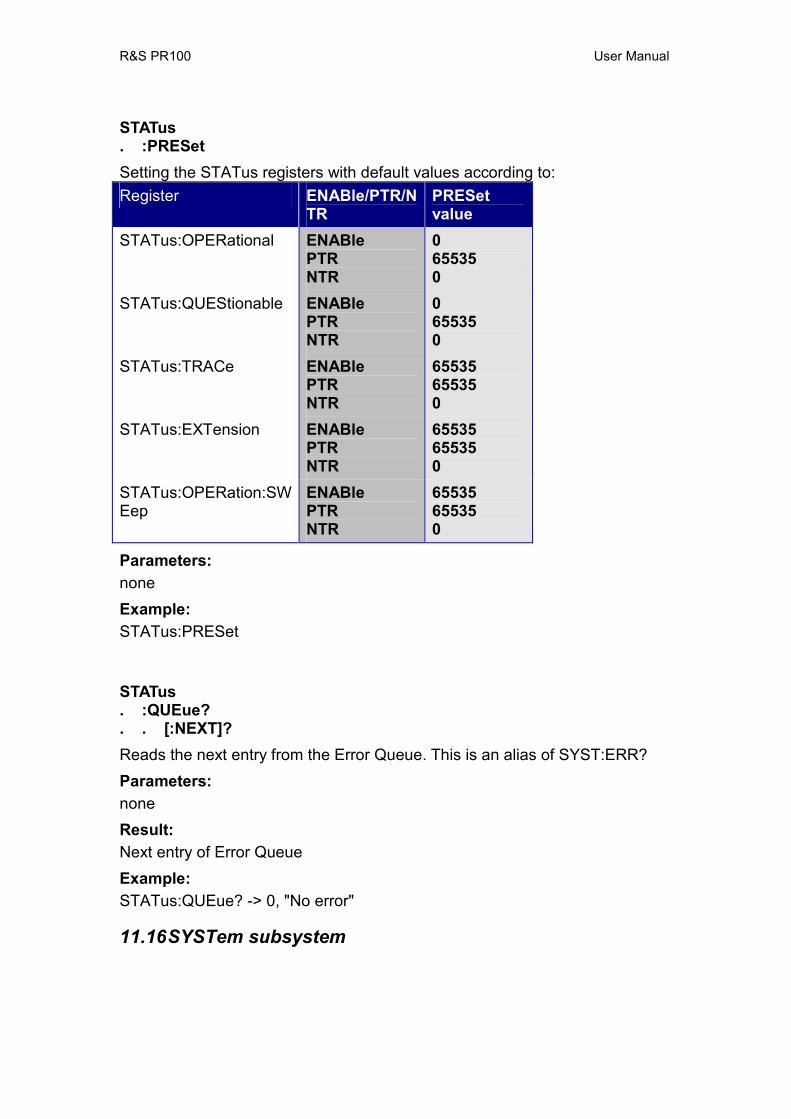
R&S PR100 User Manual
STATus . :PRESet Setting the STATus registers with default values according to: Register ENABle/PTR/N
TR PRESet value
STATus:OPERational ENABle PTR NTR
065535 0
STATus:QUEStionable ENABle PTR NTR
065535 0
STATus:TRACe ENABle PTR NTR
65535 65535 0
STATus:EXTension ENABle PTR NTR
65535 65535 0
STATus:OPERation:SWEep
ENABle PTR NTR
65535 65535 0
Parameters: none Example: STATus:PRESet
STATus . :QUEue? . . [:NEXT]? Reads the next entry from the Error Queue. This is an alias of SYST:ERR? Parameters: none Result: Next entry of Error Queue Example: STATus:QUEue? -> 0, "No error"
11.16 SYSTem subsystem
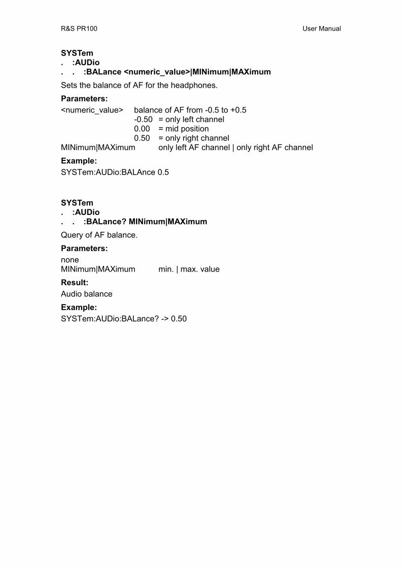
R&S PR100 User Manual
SYSTem . :AUDio . . :BALance <numeric_value>|MINimum|MAXimum Sets the balance of AF for the headphones. Parameters: <numeric_value> balance of AF from -0.5 to +0.5
-0.50 = only left channel 0.00 = mid position 0.50 = only right channel
MINimum|MAXimum only left AF channel | only right AF channel Example: SYSTem:AUDio:BALAnce 0.5
SYSTem . :AUDio . . :BALance? MINimum|MAXimum Query of AF balance. Parameters: none MINimum|MAXimum min. | max. value Result: Audio balance Example: SYSTem:AUDio:BALance? -> 0.50
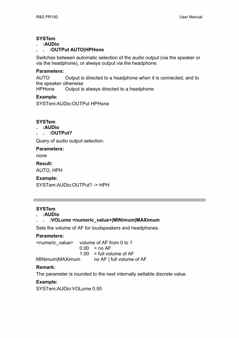
R&S PR100 User Manual
SYSTem . :AUDio . . :OUTPut AUTO|HPHone Switches between automatic selection of the audio output (via the speaker or via the headphone), or always output via the headphone. Parameters: AUTO Output is directed to a headphone when it is connected, and to the speaker otherwise HPHone Output is always directed to a headphone Example: SYSTem:AUDio:OUTPut HPHone
SYSTem . :AUDio . . :OUTPut? Query of audio output selection. Parameters: none Result: AUTO, HPH Example: SYSTem:AUDio:OUTPut? -> HPH
SYSTem . :AUDio . . :VOLume <numeric_value>|MINimum|MAXimum Sets the volume of AF for loudspeakers and headphones. Parameters: <numeric_value> volume of AF from 0 to 1
0.00 = no AF 1.00 = full volume of AF
MINimum|MAXimum no AF | full volume of AF Remark: The parameter is rounded to the next internally settable discrete value. Example: SYSTem:AUDio:VOLume 0.50

R&S PR100 User Manual
SYSTem . :AUDio . . :VOLume? [MINimum|MAXimum] Query of AF volume. Parameters: none MINimum|MAXimum min. | max. volume Result: Audio volume Example: SYSTem:AUDio:VOLume? -> 0.50
SYSTem . :BEEPer . . :VOLume <numeric_value>|MINimum|MAXimum Sets the volume of the beeper. Parameters: <numeric_value> volume of beeper from 0 to 1
0.00 = beeper off 1.00 = beeper at maximum volume
MINimum|MAXimum beeper off|beeper on Example: SYSTem:BEEPer:VOLume 0.50
SYSTem . :BEEPer . . :VOLume? [MINimum|MAXimum] Query of volume of beeper. Parameters: none MINimum|MAXimum min. | max. volume Result: Beeper volume Example: SYSTem:BEEPer:VOLume? -> 0.50
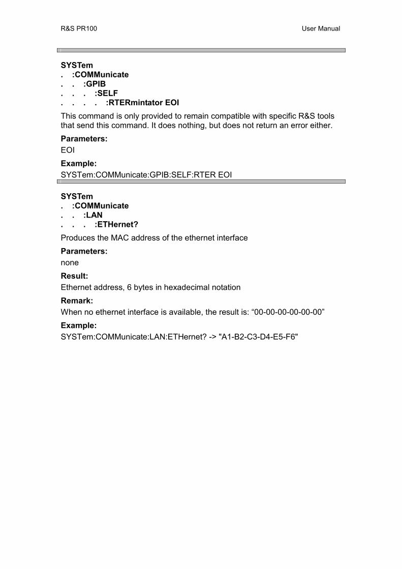
R&S PR100 User Manual
SYSTem . :COMMunicate . . :GPIB . . . :SELF . . . . :RTERmintator EOI This command is only provided to remain compatible with specific R&S tools that send this command. It does nothing, but does not return an error either. Parameters: EOI Example: SYSTem:COMMunicate:GPIB:SELF:RTER EOI
SYSTem . :COMMunicate . . :LAN . . . :ETHernet? Produces the MAC address of the ethernet interface Parameters: none Result: Ethernet address, 6 bytes in hexadecimal notation Remark: When no ethernet interface is available, the result is: “00-00-00-00-00-00” Example: SYSTem:COMMunicate:LAN:ETHernet? -> "A1-B2-C3-D4-E5-F6"
R&S PR100 User Manual
SYSTem . :COMMunicate . . :LAN . . . :SUBMask <ip-address> Sets the subnet mask of all IP communication. Note that setting this to another subnet might result in losing connection with the device.Therefore, it is most convenient to change all communication settings on the same line. The settings will not take effect until the new-line has been received. Parameters: <ip-address> string representing IP dot notation of IP address (e.g. “255.255.255.0”)
The ip-address must be a valid subnet mask according to IP specifications.
Error: In case the subnet mask is invalid, an execution error -200,"Execution error" is generated. *RST state: The mask is maintained after reset Example: SYSTem:COMMunicate:LAN:SUBMask “255.255.255.0”
SYSTem . :COMMunicate . . :LAN . . . :SUBMask? Query the subnet mask Parameter: none Result: string representing IP dot notation of IP subnet mask (e.g. “255.255.255.0”) Example: SYSTem:COMMunicate:LAN:SUBMask? -> “255.255.255.0”
R&S PR100 User Manual
SYSTem . :COMMunicate . . :SOCKet . . . :ADDRess <ip-address> Sets the IP-address of the ethernet connection of the device. Note that setting this to another address results in losing connection with the device.Therefore, it is most convenient to change all communication settings on the same line. The settings will not take effect until the new-line has been received. This only changes the address of the ethernet connection, it does not influence the USB connection. Parameters: <ip-address> string representing IP dot notation of IP address (e.g. “172.17.75.18”) Error: In case the IP address is invalid, an execution error -200,"Execution error" is generated. *RST state: The address is maintained after reset Example: SYSTem:COMMunicate:SOCKET:ADDRess “172.17.75.18”
SYSTem . :COMMunicate . . :SOCKet . . . :ADDRess? Query the IP-address of the device Parameter: none Result: string representing IP dot notation of IP address (e.g. “172.17.75.18”) Example: SYSTem:COMMunicate:SOCKet:ADDRess? -> “172.17.75.18”
R&S PR100 User Manual
SYSTem . :COMMunicate . . :SOCKet . . . :DHCP . . . . [:STATe] <Boolean> Determines whether the IP address is set automatically by the DHCP protocol. Parameters: ON Turn DHCP on (IP address determined by DHCP server in network) OFF Turn DHCP on (IP address must be set manually) Example: SYSTem:COMMunicate:SOCKET:DHCP:STATe ON
SYSTem . :COMMunicate . . :SOCKet . . . :DHCP . . . . [:STATe]? Query state of DHCP. Parameter: none Result: 0, 1 Example: SYSTem:COMMunicate:SOCKet:DHCP:STATe? -> 1
R&S PR100 User Manual
SYSTem . :COMMunicate . . :SOCKet . . . :PORT <numeric_value> Sets the IP-port number of the SCPI parser. Note that setting this to another address results in losing connection with the device.Therefore, it is most convenient to change all communication settings on the same line. The settings will not take effect until the new-line has been received. Parameters: <numeric_value> integer port number in the range [0,65535] (16 bit) Error: In case the port number is invalid, an execution error -200,"Execution error" is generated. *RST state: The port number is maintained after reset Example: SYSTem:COMMunicate:SOCKet:PORT 5555
SYSTem . :COMMunicate . . :SOCKet . . . :PORT? Query the IP-port number of the SCPI parser Parameter: none Result: integer port number in the range [0,65535] (16 bit) Example: SYSTem:COMMunicate:SOCKet:PORT? -> 5555
R&S PR100 User Manual
SYSTem . :DATE <year>, <month>, <day> Sets the current date for the device Parameters: <year> integer number in the range [2000-2099] <month> integer number in the range [1,12] (1 = January, 12 = December) <day> integer number in the range [1,31] Error: In case the date is invalid, an execution error -200,"Execution error" is generated. *RST state: The date is maintained after reset Example: SYSTem:DATE 2008, 12, 21
SYSTem . :DATE? Query the current date of the device Parameter: none Result: <year>, <month>, <day> (see SYST:DATE) Example: SYSTem:DATE? -> 2008, 12, 21
R&S PR100 User Manual
SYSTem . :ERRor . . [:NEXT]? Returns the error code and description of the error at the front of the queue. The error is also removed from the queue. Parameters: none Result: Next entry of Error Queue. If the Error Queue is empty, 0, "No error" is output Example: SYSTem:ERRor? -> 0, "No error"
SYSTem . :ERRor . . :ALL? Returns all error codes and descriptions from the Error Queue. The queue is emptied. Parameters: none Result: Comma-separated list of errod-codes and strings. If the Error Queue is empty, 0, "No Error" is output Example: SYSTem:ERRor:ALL? -> -292, “Referenced name does not exist”, -293, “Referenced name already exists”
SYSTem . :ERRor . . :CODE . . . [:NEXT]? Returns just the error code of the error at the front of the queue. The error is also removed from the queue. Parameters: none Result: Error code. If the Error Queue is empty, 0, "No error" is output Example: SYSTem:ERRor:CODE? -> 0

R&S PR100 User Manual
SYSTem . :ERRor . . :CODE . . . :ALL? Returns just the error codes of all errors in the queue, and empties the queue. Parameters: none Result: Comma-separated list of error codes. If the Error Queue is empty, 0 is output Example: SYSTem:ERRor:CODE:ALL? -> -292, -293
SYSTem . ERRor . . :COUNt? Returns the number of error messages in the queue. The queue is not emptied. Parameters: none Result: Number of errors in the queue Example: SYSTem:ERRor:COUNt? -> 0
R&S PR100 User Manual
SYSTem . :FIRMware . . :UPDate This command will update the firmware of the instrumen. Remark: The instrument will look for a new firmware version on the SD-Card. If correct firmware is found, than the firmware will be installed without any user-confirmation. Parameters: none Example: SYSTem:FIRMware:UPDate
R&S PR100 User Manual
SYSTem . :KCLick . . :VOLume <numeric_value>|MINimum|MAXimum Sets the volume of the key clicks. Parameters: <numeric_value> volume of beeper from 0 to 1
0 = key clicks off 1 = key clicks at maximum volume
MINimum|MAXimum beeper off|beeper on Example: SYSTem:KCLick:VOLume 0.5
SYSTem . :KCLick . . :VOLume? [MINimum|MAXimum] Query of volume of key clicks. Parameters: none MINimum|MAXimum min. | max. volume Result: Key-click volume Example: SYSTem:KCLick:VOLume? -> 0.50
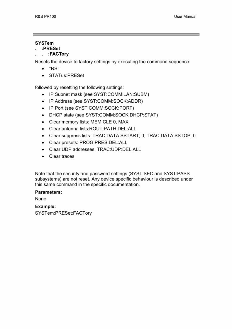
R&S PR100 User Manual
SYSTem . :PRESet . . :FACTory Resets the device to factory settings by executing the command sequence:
• *RST • STATus:PRESet
followed by resetting the following settings: • IP Subnet mask (see SYST:COMM:LAN:SUBM) • IP Address (see SYST:COMM:SOCK:ADDR) • IP Port (see SYST:COMM:SOCK:PORT) • DHCP state (see SYST:COMM:SOCK:DHCP:STAT) • Clear memory lists: MEM:CLE 0, MAX • Clear antenna lists:ROUT:PATH:DEL:ALL • Clear suppress lists: TRAC:DATA SSTART, 0; TRAC:DATA SSTOP, 0 • Clear presets: PROG:PRES:DEL:ALL • Clear UDP addresses: TRAC:UDP:DEL ALL • Clear traces
Note that the security and password settings (SYST:SEC and SYST:PASS subsystems) are not reset. Any device specific behaviour is described under this same command in the specific documentation. Parameters: None Example: SYSTem:PRESet:FACTory

R&S PR100 User Manual
SYSTem . :PRESet . . :MEASurements Reset only measurement related settings of the device.
Parameters: None Example: SYSTem:PRESet:MEASurements
SYSTem . :SECurity . . :OPTion <code> A special optional firmware can be activated by entering a certain option code. The unit must be switched on anew to activate this optional software. For a list of possible options, see the common command “*OPT?”. Remark: The SCPI interface itself is also an option. If this option is not active, none of the commands in this interface work. However, this command is an exception. When the SCPI option is not active, this command can be used to activate it. Note that no error reports can be retrieved via “SYST:ERR?”, and none of the other options can be activated as long as the SCPI option is not active. Parameters: <code> 8-digit number Error codes: -220 Parameter error incase optionkey is incorrect. *RST state: The options are maintained after a reset. Example: SYSTem:SECurity:OPTion "12345678"
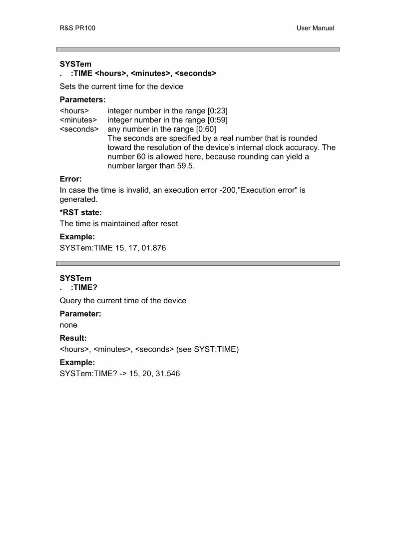
R&S PR100 User Manual
SYSTem . :TIME <hours>, <minutes>, <seconds> Sets the current time for the device Parameters: <hours> integer number in the range [0:23] <minutes> integer number in the range [0:59] <seconds> any number in the range [0:60]
The seconds are specified by a real number that is rounded toward the resolution of the device’s internal clock accuracy. The number 60 is allowed here, because rounding can yield a number larger than 59.5.
Error: In case the time is invalid, an execution error -200,"Execution error" is generated. *RST state: The time is maintained after reset Example: SYSTem:TIME 15, 17, 01.876
SYSTem . :TIME? Query the current time of the device Parameter: none Result: <hours>, <minutes>, <seconds> (see SYST:TIME) Example: SYSTem:TIME? -> 15, 20, 31.546
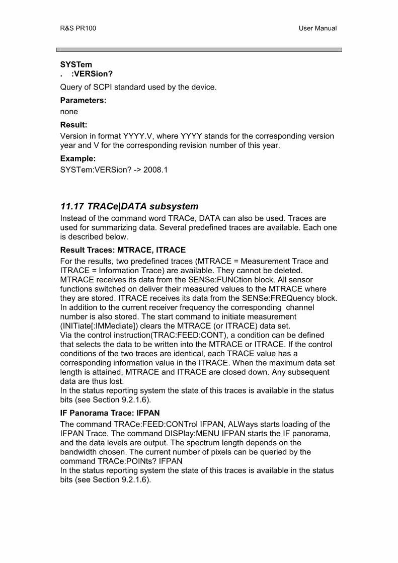
R&S PR100 User Manual
SYSTem . :VERSion? Query of SCPI standard used by the device. Parameters: none Result: Version in format YYYY.V, where YYYY stands for the corresponding version year and V for the corresponding revision number of this year. Example: SYSTem:VERSion? -> 2008.1
11.17 TRACe|DATA subsystem Instead of the command word TRACe, DATA can also be used. Traces are used for summarizing data. Several predefined traces are available. Each one is described below. Result Traces: MTRACE, ITRACE For the results, two predefined traces (MTRACE = Measurement Trace and ITRACE = Information Trace) are available. They cannot be deleted. MTRACE receives its data from the SENSe:FUNCtion block. All sensor functions switched on deliver their measured values to the MTRACE where they are stored. ITRACE receives its data from the SENSe:FREQuency block. In addition to the current receiver frequency the corresponding channel number is also stored. The start command to initiate measurement (INITiate[:IMMediate]) clears the MTRACE (or ITRACE) data set. Via the control instruction(TRAC:FEED:CONT), a condition can be defined that selects the data to be written into the MTRACE or ITRACE. If the control conditions of the two traces are identical, each TRACE value has a corresponding information value in the ITRACE. When the maximum data set length is attained, MTRACE and ITRACE are closed down. Any subsequent data are thus lost. In the status reporting system the state of this traces is available in the status bits (see Section 9.2.1.6). IF Panorama Trace: IFPAN The command TRACe:FEED:CONTrol IFPAN, ALWays starts loading of the IFPAN Trace. The command DISPlay:MENU IFPAN starts the IF panorama, and the data levels are output. The spectrum length depends on the bandwidth chosen. The current number of pixels can be queried by the command TRACe:POINts? IFPAN In the status reporting system the state of this traces is available in the status bits (see Section 9.2.1.6).
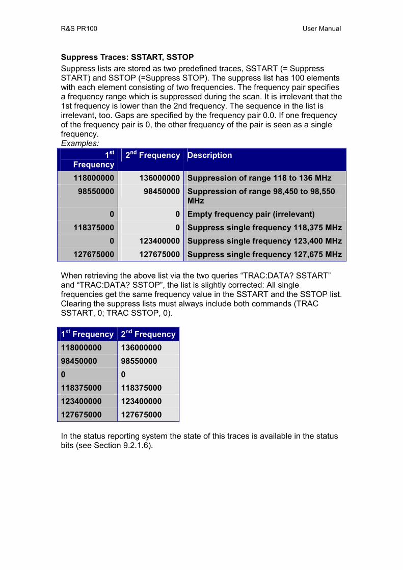
R&S PR100 User Manual
Suppress Traces: SSTART, SSTOP Suppress lists are stored as two predefined traces, SSTART (= Suppress START) and SSTOP (=Suppress STOP). The suppress list has 100 elements with each element consisting of two frequencies. The frequency pair specifies a frequency range which is suppressed during the scan. It is irrelevant that the 1st frequency is lower than the 2nd frequency. The sequence in the list is irrelevant, too. Gaps are specified by the frequency pair 0.0. If one frequency of the frequency pair is 0, the other frequency of the pair is seen as a single frequency. Examples:
1st Frequency
2nd Frequency Description
118000000 136000000 Suppression of range 118 to 136 MHz 98550000 98450000 Suppression of range 98,450 to 98,550
MHz 0 0 Empty frequency pair (irrelevant)
118375000 0 Suppress single frequency 118,375 MHz0 123400000 Suppress single frequency 123,400 MHz
127675000 127675000 Suppress single frequency 127,675 MHz
When retrieving the above list via the two queries “TRAC:DATA? SSTART” and “TRAC:DATA? SSTOP”, the list is slightly corrected: All single frequencies get the same frequency value in the SSTART and the SSTOP list. Clearing the suppress lists must always include both commands (TRAC SSTART, 0; TRAC SSTOP, 0). 1st Frequency 2nd Frequency118000000 136000000 98450000 98550000 0 0118375000 118375000 123400000 123400000 127675000 127675000
In the status reporting system the state of this traces is available in the status bits (see Section 9.2.1.6).

R&S PR100 User Manual
TRACe|DATA . :CATalog? Query of all defined trace names Parameters: none Result: "MTRACE", "ITRACE", "IFPAN", "SSTART", "SSTOP", “UDP” TRACe|DATA . [:DATA] <trace_name>, <numeric_value> , <numeric_value> | <block> Writing data to a trace. Existing data is lost. Remark: Only the suppress traces can be written to. Error: If the trace name is unknown or not identical with a suppress trace, error -141 "Invalid character data" is generated. If too many data are loaded in a suppress trace, error -223 "Too much data" is generated. Parameter: <trace-name> name of the trace to be written to
Note: These are not strings but predefined keywords. I.e.: They cannot be included in quotes.
<numeric_value> list of frequencies. If the list is not complete, the rest of the trace is filled with 0.
Note: In contrast to the SCPI standard a single value is not used for the complete trace!
<block> As an alternative to the frequency list a <Definite Length Block> can be transmitted with the following structure: Frequency list with frequencies in Hz, 8 bytes per frequency. *RST state: No change of trace contents at *RST. Example: TRACe SSTART, 123.475 MHz, 118000000, 98550 kHz

R&S PR100 User Manual
TRACe|DATA . [:DATA]? <trace_name> Query of trace data. After the query, the trace is cleared, except for the SSTART and SSTOP traces. Parameters: <trace_name> name of desired trace (MTRACE, ITRACE, IFPAN or SSTART, SSTOP) Error: If the trace name is unknown, an error -141,"Invalid character data" will be generated. Result: The output format is defined by the FORM:DATA command:
ASCii normal ASCII output PACKed Block Data, see [Orion SCPI].
The possible data-types that can be output are listed below:
Data Type C Data-Type Description “VOLTage:AC" signed short level in 1/10 dBµV"FREQuency:OFFSet" signed long offset in Hz “FSTRength" signed short field strength in 1/10 dBµV/mChannel Number unsigned
short channel number
Frequency unsigned long long
frequency in Hz
What data and in what order belong to a trace, is specified for each trace separately:
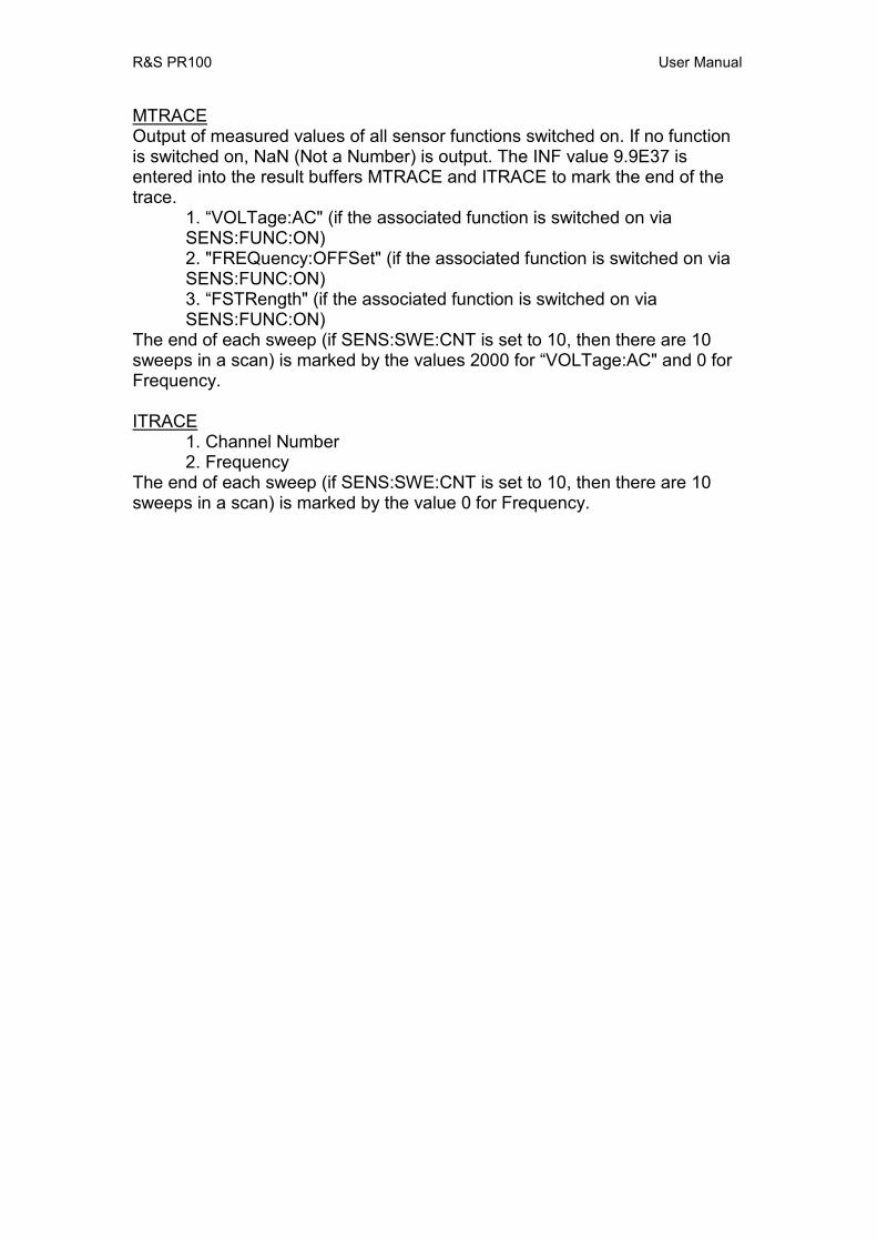
R&S PR100 User Manual
MTRACE Output of measured values of all sensor functions switched on. If no function is switched on, NaN (Not a Number) is output. The INF value 9.9E37 is entered into the result buffers MTRACE and ITRACE to mark the end of the trace.
1. “VOLTage:AC" (if the associated function is switched on via SENS:FUNC:ON) 2. "FREQuency:OFFSet" (if the associated function is switched on via SENS:FUNC:ON) 3. “FSTRength" (if the associated function is switched on via SENS:FUNC:ON)
The end of each sweep (if SENS:SWE:CNT is set to 10, then there are 10 sweeps in a scan) is marked by the values 2000 for “VOLTage:AC" and 0 for Frequency. ITRACE
1. Channel Number 2. Frequency
The end of each sweep (if SENS:SWE:CNT is set to 10, then there are 10 sweeps in a scan) is marked by the value 0 for Frequency.
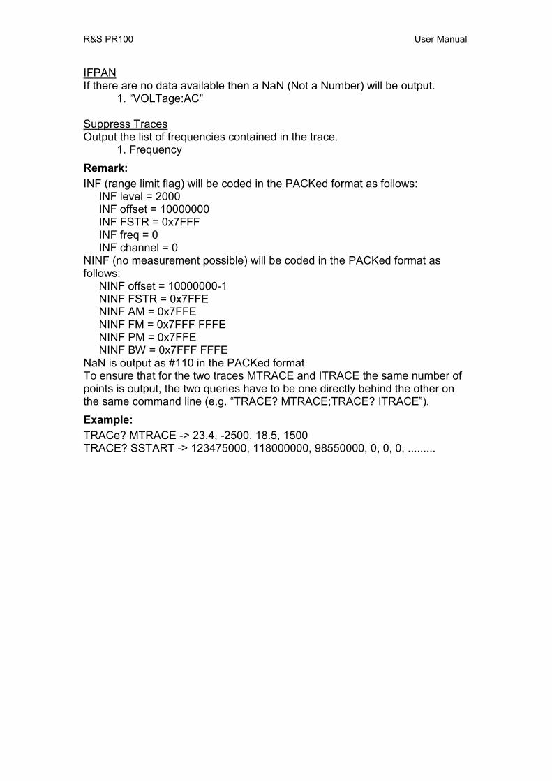
R&S PR100 User Manual
IFPANIf there are no data available then a NaN (Not a Number) will be output.
1. “VOLTage:AC" Suppress TracesOutput the list of frequencies contained in the trace.
1. Frequency Remark: INF (range limit flag) will be coded in the PACKed format as follows: INF level = 2000 INF offset = 10000000 INF FSTR = 0x7FFF INF freq = 0 INF channel = 0 NINF (no measurement possible) will be coded in the PACKed format as follows: NINF offset = 10000000-1 NINF FSTR = 0x7FFE NINF AM = 0x7FFE NINF FM = 0x7FFF FFFE NINF PM = 0x7FFE NINF BW = 0x7FFF FFFE NaN is output as #110 in the PACKed format To ensure that for the two traces MTRACE and ITRACE the same number of points is output, the two queries have to be one directly behind the other on the same command line (e.g. “TRACE? MTRACE;TRACE? ITRACE”). Example: TRACe? MTRACE -> 23.4, -2500, 18.5, 1500 TRACE? SSTART -> 123475000, 118000000, 98550000, 0, 0, 0, .........
R&S PR100 User Manual
TRACe|DATA . :FEED? <trace_name> Query of data block connected with the trace. Does not apply to SSTART and SSTOP traces. Parameters: <trace_name> see TRACe[:DATA]? Error: If the trace name is unknown, an error -141, "Invalid character data" will be generated. Result: Name of the block coupled to the trace. MTRACE: "SENS" ITRACE: "FREQ" IFPAN: "SENS" Example: TRACe:FEED? MTRACE -> "SENS"
R&S PR100 User Manual
TRACe|DATA . :FEED . . :CONTrol <trace_name>, ALWays|SQUelch|NEVer Determines how a trace is loaded with data. Data are always added to a trace; i.e. the trace is not emptied first (see also TRAC:FEED:CONT:RECM). To empty a trace, it must be read with TRACe? Parameters: <trace-name> see TRACe[:DATA]? ALWays each measurement is stored in the trace. This starts recording. SQUelch data are first stored, if the signal has exceeded the squelch threshold defined in the
OUTPut:SQUelch subsystem. This starts recording. NEVer do not store any data in the trace. This stops recording. Remark: For IFPAN Trace, only ALWays or NEVer can be selected. Error: If trace name is unknown, an error -141, "Invalid character data" will be generated. *RST state: NEVer Example: TRACe:FEED:CONTrol MTRACE, ALWays TRACe|DATA . :FEED . . :CONTrol? <trace_name> Query of how a trace is loaded with data. Parameters: <trace_name> see TRACe[:DATA]? Error: If the trace name is unknown, an error -141, "Invalid character data" will be generated. Result: ALW, SQU, NEV Example: TRACe:FEED:CONTrol? MTRACE -> ALW
R&S PR100 User Manual
TRACe|DATA . :LIMit . . [:UPPer] <trace_name>, <numeric_value>|MINimum|MAXimum Setting the limit of a trace. If the limit is exceeded, the Limit exceeded Flag will be set in the STATus:TRACe register. Parameters: <trace_name> see TRACe[:DATA]? <numeric_value> limit in percentage of the maximum trace length MINimum|MAXimum setting the least|greatest limit Error: If the trace name is unknown, an error -141, "Invalid character data" will be generated. *RST state: 50 PCT Example: TRACe:LIMit MTRACE, 50 PCT TRACe|DATA . :LIMit . . [:UPPer]? <trace_name>[,MINimum|MAXimum] Query of trace limit Parameters: <trace_name> see TRACe[:DATA]? no further parameter query of current limit MINimum|MAXimum query of least|greatest limit Error: If the trace name is unknown, an error -141, "Invalid character data" will be generated. Result: Limit in percent Example: TRACe:LIMit? MTRACE -> 50
R&S PR100 User Manual
TRACe|DATA . :POINts? <trace_name>[,MINimum|MAXimum] Query of number of values stored in a trace. The number of values stored in the suppress traces is always 100. Thus, the MAXimum and MINimum value is also 100. Parameters: <trace_name> see TRACe[:DATA]? no further parameter query of current number MINimum|MAXimum query of lowest|highest number Error: If the trace name is unknown, an error -141, "Invalid character data" will be generated. Result: Number of values Example: TRACe:POINts? MTRACE, MAX -> 2048 TRACe|DATA . :POINts . . :AUTO? <trace_name> Query of auto-adjust of trace length. This command is present to remain backward compatible. A 0 (no auto-adjust for trace length) is always output for a suppress trace, and a 1 (auto-adjust) for other traces. Parameters: <trace_name> see TRACe[:DATA]? Error: If the trace name is unknown, an error -141, "Invalid character data" will be generated. Result: 0 no auto-adjust for trace length 1 auto-adjust for trace length Example: TRACe:POINts:AUTO? MTRACE;AUTO? ITRACE -> 1;1
R&S PR100 User Manual
TRACe|DATA . :SUPPress . . :CONFig . . . :CATalog? Outputs the name of the frequency suppress-list. This name can only be modified by uploading another configuration via the TRACe:SUPP:CONFig command. Parameter: none Result: Name of suppress list files, in a format identical to that of MMEM:CAT? (see [Orion SCPI]). Example: TRACe:SUPP:CONFig:CATalog? -> 3000, 120000000 Default, .suplst, 600, 00-00-0000, 00:00:00 TRACe|DATA . :SUPPress . . :CONFig <block_data> Upload and activate a frequency suppress-list. Parameters: <block_data> block data with frequency suppress-list Example: TRACe:SUPP:CONFig <block-data specific for frequency suppress-list >
R&S PR100 User Manual
TRACe|DATA . :SUPPress . . : CONFig? Outputs the frequency suppress-list as block data. Parameters: none Result: <block_data> of file contents Example: TRACe:SUPP:CONFig? -> <block-data specific for frequency suppress-list >
R&S PR100 User Manual
TRACe|DATA . :VALue <trace_name>, <index>, <numeric_value> Setting an element of a trace. Parameters: <trace_name> name of the trace, only SSTART and SSTOP are allowed <index> Index of the element within the trace that is to be set.
The first element of a trace has the index 0. <numeric _value> frequency value of the element Remark: Only suppress traces can be set. Error: If the trace name is unknown or not equal to a suppress trace name, an error -141, "Invalid character data" is generated. *RST state: see TRACe:DATA Example: TRACe:VALue SSTART, 13, 98.550 MHz TRACe|DATA . :VALue? <trace_name>, <index> Query of an element of a trace. Parameters: <trace_name> name of the trace <index> Index of the element within the trace that is to be set.
The first element of a trace has the index 0. Remark: Only elements of the suppress traces can be queried. Error: If the trace name is unknown or not equal to a suppress trace name, an error -141 "Invalid character data " is generated. Result: Frequency value of the element of a trace in Hz Example: TRACe:Value? SSTART, 13 -> 98550000.000000
R&S PR100 User Manual
11.18 TRACe|DATA:UDP subsystem This sub-system controls what trace data are sent over UDP to a remote client. Each destination to which UDP data can be sent is called a UDP-address (which is equivalent to an IP address and port number). This sub-system keeps a list of all UDP-addresses that are used. The first item in this list is the default UDP-address, which is always present, and is retained after a power down and up. For a description of how trace data are sent over UDP see Chapter 12. TRACe|DATA . :UDP? [<numeric_value>|MINimum|MAXimum|DEFault] Query of available UDP-addresses and flags and tags that are set by the user. See Table 19 for tags and Table 20 for flags in Section 12.1.. Note that there are no predefined UDP-addresses. Each one must be entered by the user via a TRAC:UDP[:DEF]:TAG:ON and TRAC:UDP[:DEF]:FLAG:ON command. Parameters: none lists all UDP addresses as in TRACe:UDP? <numeric_value>, each on a new line <numeric_value> integer in the range [MIN, MAX] MINimum minimum index in the list of UDP-addresses (always 0) MAXimum maximum index in the list of UDP-addresses DEFault returns the index of the default UDP-address (always 0) Result: DEF|<numeric_value> [<ip-address>, <ip-port> , tag , flag ] Example: TRACe:UDP? MAX -> 3 TRACe:UDP? DEF -> 0 TRACe:UDP? 0 -> DEF
This means that the default UDP address has not yet been defined. TRACe:UDP? 0 -> DEF “123.456.789.012”, 5555, FSC, MSC, “FSTRength”
This means that field strength data is output in F-scan and M-scan data packets to port 5555 on IP address “123.456.789.012”.
TRACe:UDP? 3 -> 003 “012.123.456.789”, 4444, FSC, MSC, “VOLTage:AC” This means that received-level data is output in F-scan and M-scan data packets to port 4444 on IP address “012.123.456.789”.

R&S PR100 User Manual
TRACe|DATA . :UDP . . :DEFault . . . :FLAG . . . . :OFF <ip-address> , <ip-port>, <flag> , <flag> Changes the UDP-address of the default address and removes the specified flags if present. Parameters: <ip-address> string representing IP dot notation of IP address (e.g. 172.17.75.18) <numeric_value> integer port number in the range [0,65535] (16 bit) <flag> See Table 20 for flags in Section 12.1. *RST state: The “*RST” command has no effect on these settings. After a power down, the UDP-address list only contains the default entry (index 0). The default is retained. Example: TRACe:UDP:DEFault:FLAG:OFF “123.456.789.012”, 5555, “VOLT:AC”, “SWAP” TRACe|DATA . :UDP . . :DEFault . . . :FLAG . . . . [:ON] <ip-address> , <ip-port>, <flag> , <flag> Changes the UDP-address of the default address and adds the specified flags that determine what data is included in traces. In case a flag is added to the default address that has tags that are incompatible with this flag (e.g. “FSTRength” flag and AUDio tag), these flags are ignored for those tags. Parameters: <ip-address> string representing IP dot notation of IP address (e.g. 172.17.75.18) <numeric_value> integer port number in the range [0,65535] (16 bit) <flag> See Table 20 for flags in Section 12.1. *RST state: The “*RST” command has no effect on these settings. After a power down, the UDP-address list only contains the default entry (index 0). The default is retained. Example: TRACe:UDP:DEFault:FLAG:ON “123.456.789.012”, 5555, “VOLT:AC”, “SWAP”
R&S PR100 User Manual
TRACe|DATA . :UDP . . :DEFault . . . :TAG . . . . :OFF <ip-address> , <ip-port>, <tag> , <tag> Changes the UDP-address of the default address and removes the specified tags if present. Parameters: <ip-address> string representing IP dot notation of IP address (e.g. 172.17.75.18) <numeric_value> integer port number in the range [0,65535] (16 bit) <tag> See Table 19 for tag in Section 12.1. *RST state: The “*RST” command has no effect on these settings. After a power down, the UDP-address list only contains the default entry (index 0). The default is retained. Example: TRACe:UDP:DEFault:TAG:OFF “123.456.789.012”, 5555, MSC, FSC
R&S PR100 User Manual
TRACe|DATA . :UDP . . :DEFault . . . :TAG . . . . [:ON] <ip-address> , <ip-port>, <tag> , <tag> Changes the UDP-address of the default address and adds the specified tags that determine what data is included in traces. In case a tag is added to the default address that has flags that are incompatible with this tag (e.g. “FSTRength” flag and AUDio tag), these flags are ignored for those tags. All tags and flags are off by default, but specifying the IFPan tag automatically includes the flag “VOLTage:AC”. Parameters: <ip-address> string representing IP dot notation of IP address (e.g. 172.17.75.18) <numeric_value> integer port number in the range [0,65535] (16 bit) <tag> See Table 19 for tag in Section 12.1. *RST state: The “*RST” command has no effect on these settings. After a power down, the UDP-address list only contains the default entry (index 0). The default is retained. Example: TRACe:UDP:DEFault:TAG:ON “123.456.789.012”, 5555, MSC, FSC TRACe|DATA . :UDP . . :DELete ALL| (<ip-address>, <ip-port>) Deletes one UDP-addresses from the list, or all of them including the default one (index 0). Parameters: ALL All UDP-addresses are deleted, including the default one (index 0) <ip-address>, <ip-port> The UDP-address that matches the IP address and the port is deleted. *RST state: none, as command is an event Example: TRACe:UDP:DELete ALL TRACe:UDP:DELete “012.123.456.789”, 4444
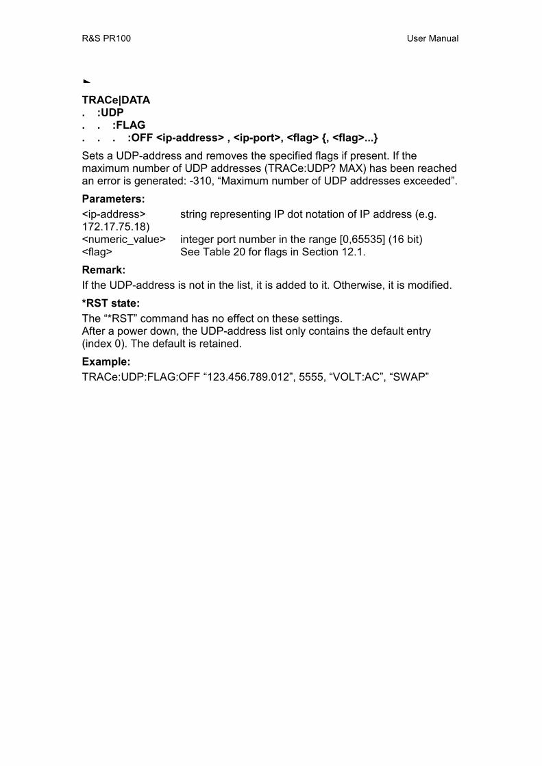
R&S PR100 User Manual
TRACe|DATA . :UDP . . :FLAG . . . :OFF <ip-address> , <ip-port>, <flag> , <flag>... Sets a UDP-address and removes the specified flags if present. If the maximum number of UDP addresses (TRACe:UDP? MAX) has been reached an error is generated: -310, “Maximum number of UDP addresses exceeded”. Parameters: <ip-address> string representing IP dot notation of IP address (e.g. 172.17.75.18) <numeric_value> integer port number in the range [0,65535] (16 bit) <flag> See Table 20 for flags in Section 12.1. Remark: If the UDP-address is not in the list, it is added to it. Otherwise, it is modified. *RST state: The “*RST” command has no effect on these settings. After a power down, the UDP-address list only contains the default entry (index 0). The default is retained. Example: TRACe:UDP:FLAG:OFF “123.456.789.012”, 5555, “VOLT:AC”, “SWAP”

R&S PR100 User Manual
TRACe|DATA . :UDP . . :FLAG . . . [:ON] <ip-address> , <ip-port>, <flag> , <flag>... Sets a UDP-address and adds the specified flags that determine what data is included in traces. If the maximum number of UDP addresses (TRACe:UDP? MAX) has been reached an error is generated: -310, “Maximum number of UDP addresses exceeded”. In case a flag is added to a UDP address that has tags that are incompatible with this flag (e.g. “FSTRength” flag and AUDio tag), these flags are ignored for those tags. All tags and flags are off by default, but specifying the IFPan tag automatically includes the flag “VOLTage:AC”. Parameters: <ip-address> string representing IP dot notation of IP address (e.g. 172.17.75.18) <numeric_value> integer port number in the range [0,65535] (16 bit) <flag> See Table 20 for flags in Section 12.1. Remark: If the UDP-address is not in the list, it is added to it. Otherwise, it is modified *RST state: The “*RST” command has no effect on these settings. After a power down, the UDP-address list only contains the default entry (index 0). The default is retained. Example: TRACe:UDP:FLAG:ON “123.456.789.012”, 5555, “VOLT:AC”, “SWAP”
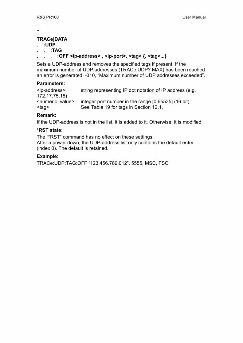
R&S PR100 User Manual
TRACe|DATA . :UDP . . :TAG . . . :OFF <ip-address> , <ip-port>, <tag> , <tag>... Sets a UDP-address and removes the specified tags if present. If the maximum number of UDP addresses (TRACe:UDP? MAX) has been reached an error is generated: -310, “Maximum number of UDP addresses exceeded”. Parameters: <ip-address> string representing IP dot notation of IP address (e.g. 172.17.75.18) <numeric_value> integer port number in the range [0,65535] (16 bit) <tag> See Table 19 for tags in Section 12.1. Remark: If the UDP-address is not in the list, it is added to it. Otherwise, it is modified *RST state: The “*RST” command has no effect on these settings. After a power down, the UDP-address list only contains the default entry (index 0). The default is retained. Example: TRACe:UDP:TAG:OFF “123.456.789.012”, 5555, MSC, FSC
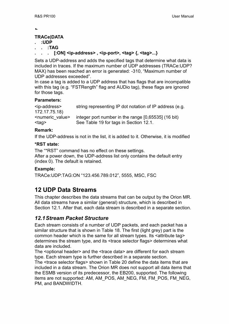
R&S PR100 User Manual
TRACe|DATA . :UDP . . :TAG . . . [:ON] <ip-address> , <ip-port>, <tag> , <tag>... Sets a UDP-address and adds the specified tags that determine what data is included in traces. If the maximum number of UDP addresses (TRACe:UDP? MAX) has been reached an error is generated: -310, “Maximum number of UDP addresses exceeded”. In case a tag is added to a UDP address that has flags that are incompatible with this tag (e.g. “FSTRength” flag and AUDio tag), these flags are ignored for those tags. Parameters: <ip-address> string representing IP dot notation of IP address (e.g. 172.17.75.18) <numeric_value> integer port number in the range [0,65535] (16 bit) <tag> See Table 19 for tags in Section 12.1. Remark: If the UDP-address is not in the list, it is added to it. Otherwise, it is modified *RST state: The “*RST” command has no effect on these settings. After a power down, the UDP-address list only contains the default entry (index 0). The default is retained. Example: TRACe:UDP:TAG:ON “123.456.789.012”, 5555, MSC, FSC
12 UDP Data Streams This chapter describes the data streams that can be output by the Orion MR. All data streams have a similar (general) structure, which is described in Section 12.1. After that, each data stream is described in a separate section.
12.1 Stream Packet Structure Each stream consists of a number of UDP packets, and each packet has a similar structure that is shown in Table 18. The first (light grey) part is the common header which is the same for all stream types. Its <attribute tag> determines the stream type, and its <trace selector flags> determines what data are included. The <optional header> and the <trace data> are different for each stream type. Each stream type is further described in a separate section. The <trace selector flags> shown in Table 20 define the data items that are included in a data stream. The Orion MR does not support all data items that the ESMB version of its predecessor, the EB200, supported. The following items are not supported: AM, AM_POS, AM_NEG, FM, FM_POS, FM_NEG, PM, and BANDWIDTH.
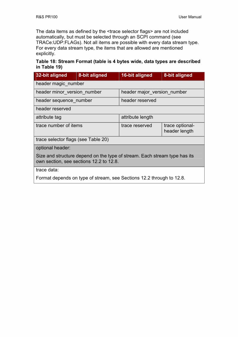
R&S PR100 User Manual
The data items as defined by the <trace selector flags> are not included automatically, but must be selected through an SCPI command (see TRACe:UDP:FLAGs). Not all items are possible with every data stream type. For every data stream type, the items that are allowed are mentioned explicitly. Table 18: Stream Format (table is 4 bytes wide, data types are described in Table 19) 32-bit aligned 8-bit aligned 16-bit aligned 8-bit aligned
header magic_number
header minor_version_number header major_version_number
header sequence_number header reserved
header reserved
attribute tag attribute length
trace number of items trace reserved trace optional-header length
trace selector flags (see Table 20)
optional header:
Size and structure depend on the type of stream. Each stream type has its own section, see sections 12.2 to 12.8.
trace data:
Format depends on type of stream, see Sections 12.2 through to 12.8.
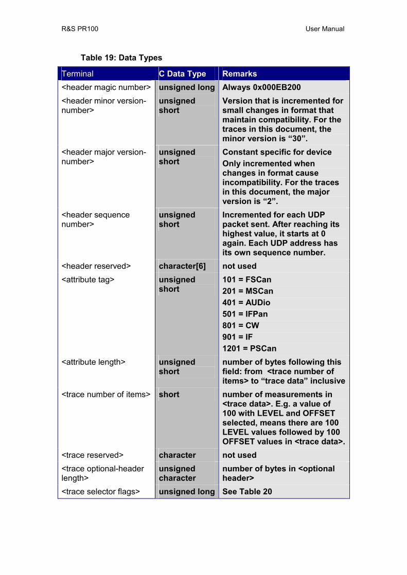
R&S PR100 User Manual
Table 19: Data Types
Terminal C Data Type Remarks <header magic number> unsigned long Always 0x000EB200 <header minor version-number>
unsigned short
Version that is incremented for small changes in format that maintain compatibility. For the traces in this document, the minor version is “30”.
<header major version-number>
unsigned short
Constant specific for device Only incremented when changes in format cause incompatibility. For the traces in this document, the major version is “2”.
<header sequence number>
unsigned short
Incremented for each UDP packet sent. After reaching its highest value, it starts at 0 again. Each UDP address has its own sequence number.
<header reserved> character[6] not used <attribute tag> unsigned
short 101 = FSCan 201 = MSCan 401 = AUDio 501 = IFPan 801 = CW 901 = IF 1201 = PSCan
<attribute length> unsigned short
number of bytes following this field: from <trace number of items> to “trace data” inclusive
<trace number of items> short number of measurements in <trace data>. E.g. a value of 100 with LEVEL and OFFSET selected, means there are 100 LEVEL values followed by 100 OFFSET values in <trace data>.
<trace reserved> character not used <trace optional-header length>
unsigned character
number of bytes in <optional header>
<trace selector flags> unsigned long See Table 20
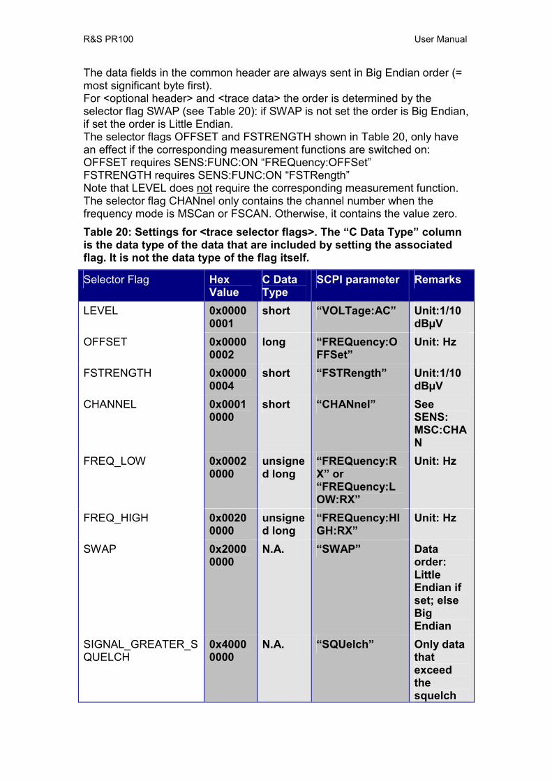
R&S PR100 User Manual
The data fields in the common header are always sent in Big Endian order (= most significant byte first). For <optional header> and <trace data> the order is determined by the selector flag SWAP (see Table 20): if SWAP is not set the order is Big Endian, if set the order is Little Endian. The selector flags OFFSET and FSTRENGTH shown in Table 20, only have an effect if the corresponding measurement functions are switched on: OFFSET requires SENS:FUNC:ON “FREQuency:OFFSet” FSTRENGTH requires SENS:FUNC:ON “FSTRength” Note that LEVEL does not require the corresponding measurement function. The selector flag CHANnel only contains the channel number when the frequency mode is MSCan or FSCAN. Otherwise, it contains the value zero. Table 20: Settings for <trace selector flags>. The “C Data Type” column is the data type of the data that are included by setting the associated flag. It is not the data type of the flag itself.
Selector Flag Hex Value
C Data Type
SCPI parameter Remarks
LEVEL 0x00000001
short “VOLTage:AC” Unit:1/10 dBµV
OFFSET 0x00000002
long “FREQuency:OFFSet”
Unit: Hz
FSTRENGTH 0x00000004
short “FSTRength” Unit:1/10 dBµV
CHANNEL 0x00010000
short “CHANnel” See SENS: MSC:CHAN
FREQ_LOW 0x00020000
unsigned long
“FREQuency:RX” or “FREQuency:LOW:RX”
Unit: Hz
FREQ_HIGH 0x00200000
unsigned long
“FREQuency:HIGH:RX”
Unit: Hz
SWAP 0x20000000
N.A. “SWAP” Data order: Little Endian if set; else Big Endian
SIGNAL_GREATER_SQUELCH
0x40000000
N.A. “SQUelch” Only data that exceed the squelch

R&S PR100 User Manual
level are included
OPTIONAL_HEADER 0x80000000
N.A. “OPTional” Optional header is included
Note: The Selector flag “FREQuency:LOW:RX” and “FREQuency:RX” are the same. The “FREQuency:RX” flag is compatible with the older receivers and supports frequencies < 4 GHz. Since the PR100 frequency range is > 4 GHz a new flag FREQuency:HIGH:RX is introduced. Backwards compatibility is realized by adding the higher 32 bits of a frequency at the end of the optional header. Empty packets (also those with an optional header but without data) are not transmitted. For packets that contain scan data (for FSCan, MSCan, and PSCan), the end of a sweep (scan) is marked: The last item in a scan is always followed by an end-marker. This end-marker is another item with unrealistic values: Table 21, End Markers
Data Type Value Unit LEVEL 2000 dBµVOFFSET 10 000 000 Hz FSTRENGTH 32 767 dBµV/mCHANNEL 0FREQ_LOW 0 Hz FREQ_HIGH 0 Hz
Note that the end-marker is counted in the header field <trace number of items>. E.g.: An FSCan from 100 MHz to 110 MHz with a 1 MHz step width outputs 12 items: 11 measured items and 1 end-marker.
12.2 Audio The audio stream is only active if SYST:AUD:REM:MODE has been set to anything else but 0 (zero). It is further determined by two parameters:
• Audio mode: determines the data-rate and the format of the audio samples
• Audio demodulation: determines the demodulation used to obtain the audio samples, e.g. AM or FM
The applicable selector flags (see Table 20) are “OPTIONAL_HEADER” and “SWAP”. The header field <trace number of items> is the number of frames (see Table 25) in a packet.

R&S PR100 User Manual
Table 22: Audio Format <optional header> and <trace data> 32-bit aligned 8-bit aligned 16-bit aligned 8-bit aligned
Audio mode Audio frame len
Audio frequency low (4 bytes)
Audio bandwidth
Audio demodulation id Audio demodulation mode (8 bytes)
Audio frequency high (4 bytes)
reserved (2bytes)(
trace data: see Table 25, depends on Audio mode
Table 23: Audio Data Types
Terminal C Data Type Remarks <AUDio audio mode> short See Table 25 (Format ID) <AUDio frame len> short See Table 25 (Frame Length) <AUDio frequency low> unsigned long Lower 32 bits of output of
SENS:FREQ:CW? in Hz <AUDio bandwidth> unsigned long Output of SENS:BAND:RES? in
Hz <AUDio demodulation id>
unsigned short
Output of SENS:DEM? acc. to Table 24 (Identifier column)
<AUDio demodulation mode>
char[8] See column “Demodulation-Mode” in Table 24.
<AUDio frequency high> unsigned long Upper 32 bits of output of SENS:FREQ:CW? in Hz
Table 24: Demodulation Modes and Identifiers (modes 0 – 6 are compatible with EB200)
Demodulation-Mode Identifier Req. EB200 FM 0 SFD096 CompatibleAM 1 SFD095 CompatiblePULS 2 SFD0102 CompatibleCW 3 SFD0100 CompatibleUSB 4 SFD097 CompatibleLSB 5 SFD098 Compatible

R&S PR100 User Manual
IQ 6 SFD0101 CompatibleISB 7 SFD099 New
Table 25: Audio Data Formats (All Compatible with EB200, Req. SFD0247, except for the GSM format that is not supported in the Orion MR). Each channel is sampled at a certain rate (second column) with a number of bits accuracy (third column). There is one special format in this table, mode 0, in which no data is sent.
Format ID Sample Rate [kHz]
Bit per Sample
Channels Data Rate [kByte/s]
Frame Length [Bytes]
0 - - - 0 -1 32 16 2 128 42 32 16 1 64 23 32 8 2 64 24 32 8 1 32 15 16 16 2 64 46 16 16 1 32 27 16 8 2 32 28 16 8 1 16 19 8 16 2 32 410 8 16 1 16 211 8 8 2 16 212 8 8 1 8 1
12.3 FScan The Orion MR can provide 2000 measurements per second (minimum MEAS:TIME is 0.5 ms; Req. SFD0172). For each measurement, LEVEL, OFFSET, FSTRENGTH, CHANNEL, FREQ_LOW and FREQ_HIGH can be included into this stream, which is 16 bytes per measurement. All selector flags (see Table 20) are applicable for this stream Data are output when FSCAN is running. Table 26: FScan Format <optional header> and <trace data>. 32-bit aligned 8-bit aligned 16-bit aligned 8-bit aligned FScan cycle count FScan hold time
FScan dwell time FScan direction up
FScan stop signal FScan start frequency low (4 bytes)
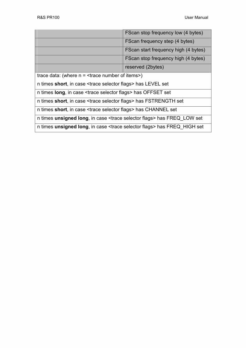
R&S PR100 User Manual
FScan stop frequency low (4 bytes)
FScan frequency step (4 bytes)
FScan start frequency high (4 bytes)
FScan stop frequency high (4 bytes)
reserved (2bytes)
trace data: (where n = <trace number of items>)
n times short, in case <trace selector flags> has LEVEL set
n times long, in case <trace selector flags> has OFFSET set
n times short, in case <trace selector flags> has FSTRENGTH set
n times short, in case <trace selector flags> has CHANNEL set
n times unsigned long, in case <trace selector flags> has FREQ_LOW set
n times unsigned long, in case <trace selector flags> has FREQ_HIGH set
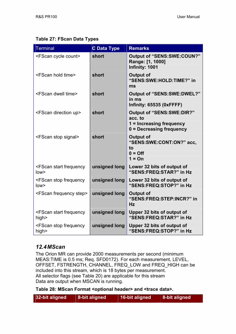
R&S PR100 User Manual
Table 27: FScan Data Types
Terminal C Data Type Remarks <FScan cycle count> short Output of “SENS:SWE:COUN?”
Range: [1, 1000] Infinity: 1001
<FScan hold time> short Output of “SENS:SWE:HOLD:TIME?” in ms
<FScan dwell time> short Output of “SENS:SWE:DWEL?” in ms Infinity: 65535 (0xFFFF)
<FScan direction up> short Output of “SENS:SWE:DIR?” acc. to 1 = Increasing frequency 0 = Decreasing frequency
<FScan stop signal> short Output of “SENS:SWE:CONT:ON?” acc, to 0 = Off 1 = On
<FScan start frequency low>
unsigned long Lower 32 bits of output of “SENS:FREQ:STAR?” in Hz
<FScan stop frequency low>
unsigned long Lower 32 bits of output of “SENS:FREQ:STOP?” in Hz
<FScan frequency step> unsigned long Output of “SENS:FREQ:STEP:INCR?” in Hz
<FScan start frequency high>
unsigned long Upper 32 bits of output of “SENS:FREQ:STAR?” in Hz
<FScan stop frequency high>
unsigned long Upper 32 bits of output of “SENS:FREQ:STOP?” in Hz
12.4 MScan The Orion MR can provide 2000 measurements per second (minimum MEAS:TIME is 0.5 ms; Req. SFD0172). For each measurement, LEVEL, OFFSET, FSTRENGTH, CHANNEL, FREQ_LOW and FREQ_HIGH can be included into this stream, which is 18 bytes per measurement. All selector flags (see Table 20) are applicable for this stream Data are output when MSCAN is running. Table 28: MScan Format <optional header> and <trace data>. 32-bit aligned 8-bit aligned 16-bit aligned 8-bit aligned
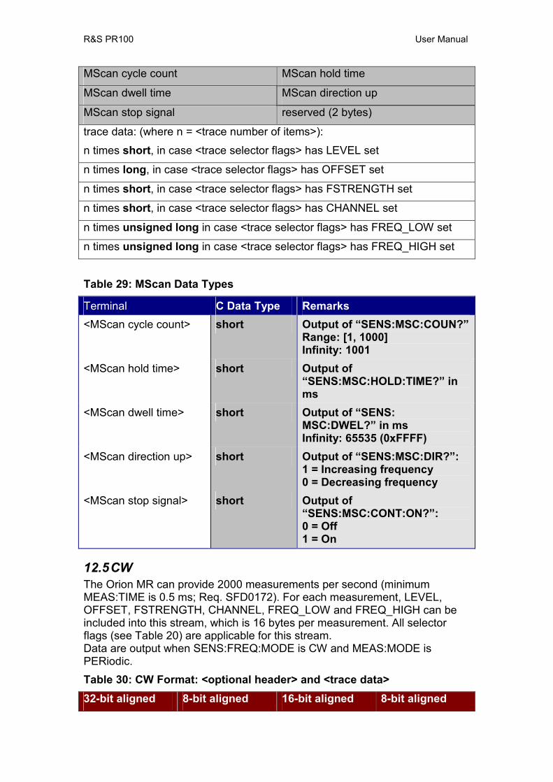
R&S PR100 User Manual
MScan cycle count MScan hold time
MScan dwell time MScan direction up
MScan stop signal reserved (2 bytes)
trace data: (where n = <trace number of items>):
n times short, in case <trace selector flags> has LEVEL set
n times long, in case <trace selector flags> has OFFSET set
n times short, in case <trace selector flags> has FSTRENGTH set
n times short, in case <trace selector flags> has CHANNEL set
n times unsigned long in case <trace selector flags> has FREQ_LOW set
n times unsigned long in case <trace selector flags> has FREQ_HIGH set
Table 29: MScan Data Types
Terminal C Data Type Remarks <MScan cycle count> short Output of “SENS:MSC:COUN?”
Range: [1, 1000] Infinity: 1001
<MScan hold time> short Output of “SENS:MSC:HOLD:TIME?” in ms
<MScan dwell time> short Output of “SENS: MSC:DWEL?” in ms Infinity: 65535 (0xFFFF)
<MScan direction up> short Output of “SENS:MSC:DIR?”: 1 = Increasing frequency 0 = Decreasing frequency
<MScan stop signal> short Output of “SENS:MSC:CONT:ON?”: 0 = Off 1 = On
12.5 CW The Orion MR can provide 2000 measurements per second (minimum MEAS:TIME is 0.5 ms; Req. SFD0172). For each measurement, LEVEL, OFFSET, FSTRENGTH, CHANNEL, FREQ_LOW and FREQ_HIGH can be included into this stream, which is 16 bytes per measurement. All selector flags (see Table 20) are applicable for this stream. Data are output when SENS:FREQ:MODE is CW and MEAS:MODE is PERiodic. Table 30: CW Format: <optional header> and <trace data> 32-bit aligned 8-bit aligned 16-bit aligned 8-bit aligned
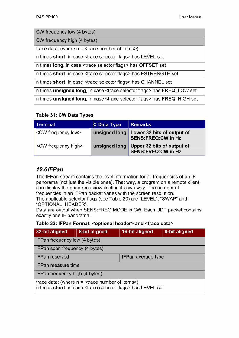
R&S PR100 User Manual
CW frequency low (4 bytes)
CW frequency high (4 bytes)
trace data: (where n = <trace number of items>)
n times short, in case <trace selector flags> has LEVEL set
n times long, in case <trace selector flags> has OFFSET set
n times short, in case <trace selector flags> has FSTRENGTH set
n times short, in case <trace selector flags> has CHANNEL set
n times unsigned long, in case <trace selector flags> has FREQ_LOW set
n times unsigned long, in case <trace selector flags> has FREQ_HIGH set
Table 31: CW Data Types
Terminal C Data Type Remarks <CW frequency low> unsigned long Lower 32 bits of output of
SENS:FREQ:CW in Hz <CW frequency high> unsigned long Upper 32 bits of output of
SENS:FREQ:CW in Hz
12.6 IFPan The IFPan stream contains the level information for all frequencies of an IF panorama (not just the visible ones). That way, a program on a remote client can display the panorama view itself in its own way. The number of frequencies in an IFPan packet varies with the screen resolution. The applicable selector flags (see Table 20) are “LEVEL”, “SWAP” and “OPTIONAL_HEADER”. Data are output when SENS:FREQ:MODE is CW. Each UDP packet contains exactly one IF panorama. Table 32: IFPan Format: <optional header> and <trace data> 32-bit aligned 8-bit aligned 16-bit aligned 8-bit aligned
IFPan frequency low (4 bytes)
IFPan span frequency (4 bytes)
IFPan reserved IFPan average type
IFPan measure time
IFPan frequency high (4 bytes)
trace data: (where n = <trace number of items>) n times short, in case <trace selector flags> has LEVEL set

R&S PR100 User Manual
Table 33: IFPan Data Types
Terminal C Data Type Remarks <IFPan frequency low> unsigned long Lower 32 bit of center of IFPan
span (“SENS:FREQ:CW?”) in Hz
<IFPan span frequency>
unsigned long Output of “SENS:FREQ:SPAN?” in Hz
<IFPan reserved> Short Always 0; this field is not used <IFPan average type> Short Always set to OFF (3),
regardless of the output of “CALC:IFP:AVER:TYPE?”.
<IFPan measure time> unsigned long Output of “MEAS:TIME?” in µs. 0 µs is used for DEFault.
<IFPan frequency high> unsigned long Upper 32 bit of center of IFPan span (“SENS:FREQ:CW?”) in Hz
12.7 IF The IF stream contains source IQ data. Although the Audio stream can also contain data in IQ form, it is not the same as this stream. This stream is the source for the audio demodulation: The Audio IQ is obtained by processing this stream. For the IF stream, the data rate can be very high: 640 kSamples/second (Req. SFD0248). It has 2 channels and 16 bit per sample. At the maximum sample rate of 640k per second, the total data-rate is 2.56 MByte/s. The only applicable selector flag is “OPTIONAL_HEADER”. All other flags have no influence on the format of the IF stream. Data is always sent with the SWAP flag set, independent of whether the SWAP flag has been configured for this stream or not. Data are output when no PSCAN/FSCAN/MSCAN is running, and additionally also during the HOLD state in a running FSCAN/MSCAN. Table 34: IF Format: <optional header> and <trace data> 32-bit aligned 8-bit aligned 16-bit aligned 8-bit aligned
IF mode IF frame length
IF sample rate
IF frequency low (4 bytes)
IF bandwidth
IF demodulation id IF RX attenuation
IF flags IF reserved (2 bytes)
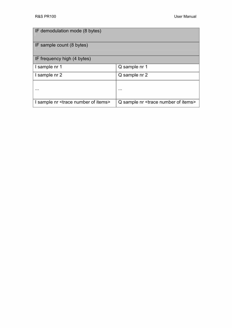
R&S PR100 User Manual
IF demodulation mode (8 bytes)
IF sample count (8 bytes)
IF frequency high (4 bytes)
I sample nr 1 Q sample nr 1
I sample nr 2 Q sample nr 2
...
...
I sample nr <trace number of items> Q sample nr <trace number of items>
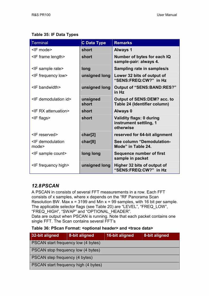
R&S PR100 User Manual
Table 35: IF Data Types
Terminal C Data Type Remarks <IF mode> short Always 1 <IF frame length> short Number of bytes for each IQ
sample-pair: always 4. <IF sample rate> long Sampling rate in samples/s <IF frequency low> unsigned long Lower 32 bits of output of
“SENS:FREQ:CW?” in Hz <IF bandwidth> unsigned long Output of “SENS:BAND:RES?”
in Hz <IF demodulation id> unsigned
short Output of SENS:DEM? acc. to Table 24 (Identifier column)
<IF RX attenuation> short Always 0 <IF flags> short Validity flags: 0 during
instrument settling, 1 otherwise
<IF reserved> char[2] reserved for 64-bit alignment <IF demodulation mode>
char[8] See column “Demodulation-Mode” in Table 24.
<IF sample count> long long Sequence number of first sample in packet
<IF frequency high> unsigned long Higher 32 bits of output of “SENS:FREQ:CW?” in Hz
12.8 PSCAN A PSCAN in consists of several FFT measurements in a row. Each FFT consists of x samples, where x depends on the “RF Panorama Scan Resolution BW. Max x = 3199 and Min x = 99 samples, with 16 bit per sample. The applicable selector flags (see Table 20) are “LEVEL”, “FREQ_LOW”, “FREQ_HIGH”, “SWAP” and “OPTIONAL_HEADER”. Data are output when PSCAN is running. Note that each packet contains one single FFT. The Scan contains several FFT’s Table 36: PScan Format: <optional header> and <trace data> 32-bit aligned 8-bit aligned 16-bit aligned 8-bit aligned
PSCAN start frequency low (4 bytes)
PSCAN stop frequency low (4 bytes)
PSCAN step frequency (4 bytes)
PSCAN start frequency high (4 bytes)
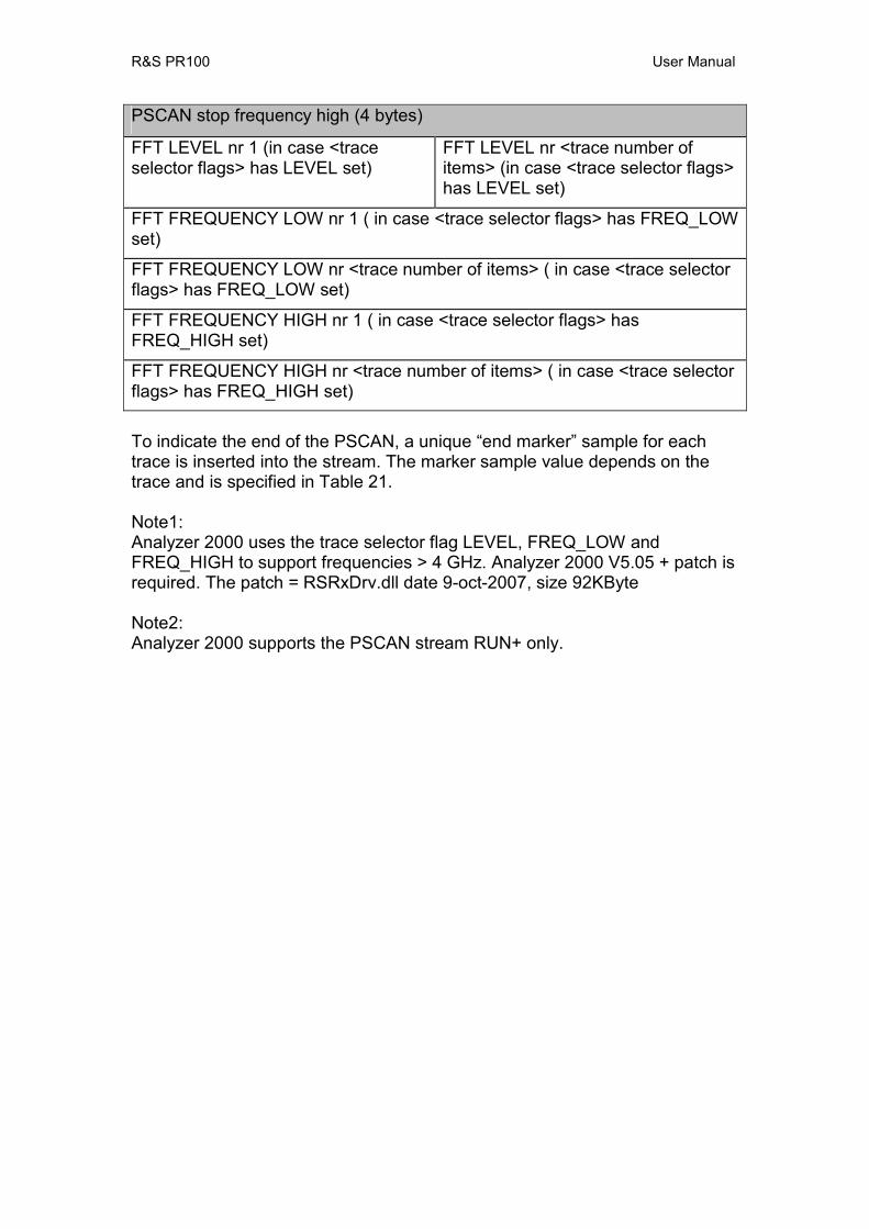
R&S PR100 User Manual
PSCAN stop frequency high (4 bytes)
FFT LEVEL nr 1 (in case <trace selector flags> has LEVEL set)
FFT LEVEL nr <trace number of items> (in case <trace selector flags> has LEVEL set)
FFT FREQUENCY LOW nr 1 ( in case <trace selector flags> has FREQ_LOW set)
FFT FREQUENCY LOW nr <trace number of items> ( in case <trace selector flags> has FREQ_LOW set)
FFT FREQUENCY HIGH nr 1 ( in case <trace selector flags> has FREQ_HIGH set)
FFT FREQUENCY HIGH nr <trace number of items> ( in case <trace selector flags> has FREQ_HIGH set)
To indicate the end of the PSCAN, a unique “end marker” sample for each trace is inserted into the stream. The marker sample value depends on the trace and is specified in Table 21. Note1: Analyzer 2000 uses the trace selector flag LEVEL, FREQ_LOW and FREQ_HIGH to support frequencies > 4 GHz. Analyzer 2000 V5.05 + patch is required. The patch = RSRxDrv.dll date 9-oct-2007, size 92KByte Note2: Analyzer 2000 supports the PSCAN stream RUN+ only.
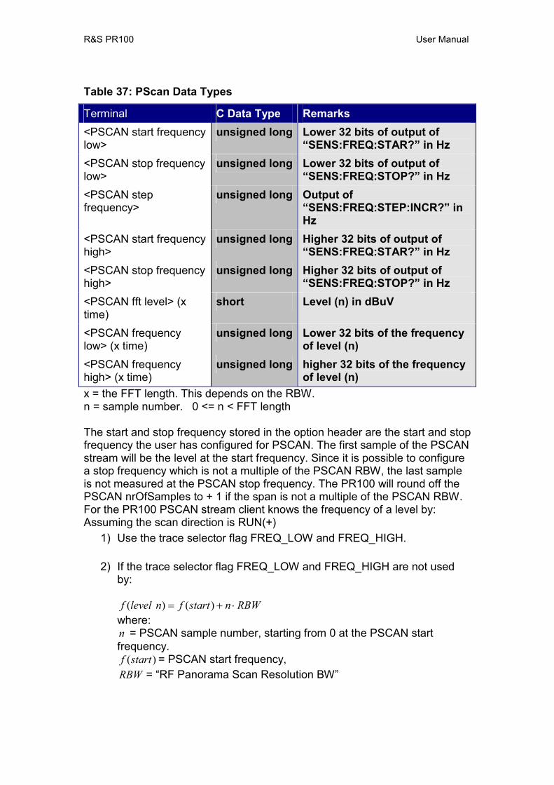
R&S PR100 User Manual
Table 37: PScan Data Types
Terminal C Data Type Remarks <PSCAN start frequency low>
unsigned long Lower 32 bits of output of “SENS:FREQ:STAR?” in Hz
<PSCAN stop frequency low>
unsigned long Lower 32 bits of output of “SENS:FREQ:STOP?” in Hz
<PSCAN step frequency>
unsigned long Output of “SENS:FREQ:STEP:INCR?” in Hz
<PSCAN start frequency high>
unsigned long Higher 32 bits of output of “SENS:FREQ:STAR?” in Hz
<PSCAN stop frequency high>
unsigned long Higher 32 bits of output of “SENS:FREQ:STOP?” in Hz
<PSCAN fft level> (x time)
short Level (n) in dBuV
<PSCAN frequency low> (x time)
unsigned long Lower 32 bits of the frequency of level (n)
<PSCAN frequency high> (x time)
unsigned long higher 32 bits of the frequency of level (n)
x = the FFT length. This depends on the RBW. n = sample number. 0 <= n < FFT length The start and stop frequency stored in the option header are the start and stop frequency the user has configured for PSCAN. The first sample of the PSCAN stream will be the level at the start frequency. Since it is possible to configure a stop frequency which is not a multiple of the PSCAN RBW, the last sample is not measured at the PSCAN stop frequency. The PR100 will round off the PSCAN nrOfSamples to + 1 if the span is not a multiple of the PSCAN RBW. For the PR100 PSCAN stream client knows the frequency of a level by: Assuming the scan direction is RUN(+)
1) Use the trace selector flag FREQ_LOW and FREQ_HIGH.
2) If the trace selector flag FREQ_LOW and FREQ_HIGH are not used by:
RBWnstartfnlevelf ⋅+= )()(where: n = PSCAN sample number, starting from 0 at the PSCAN start frequency.
)(startf = PSCAN start frequency, RBW = “RF Panorama Scan Resolution BW”

R&S PR100 User Manual
Figure 5 shows the payload of a PSCAN UDP package where the trace selector flags “LEVEL”, “FREQ_LOW”, “FREQ_HIGH”, and “OPTIONAL_HEADER” are set. A PSCAN cycle is a single scan from start till the stop frequency. The last sample of a cycle will be the “end marker” value. A single PSCAN cycle consist of 1 or more PSCAN UDP packges.
Figure 5 Payload PSCAN UDP Package Note The PSCAN stream is available during a running PSCAN only.
• To enable a PSCAN stream including LEVEL, FREQ_LOW and FREQ_HIGH: If stream client is 172.17.75.50:19000 : Trace:Udp:Tag:On "172.17.75.50", 19000, PSCAN Trace:udp:flag:on "172.17.75.1", 19000, "FREQ:LOW:rx", "FREQ:HIGH:rx", "VOLT:AC"
• To get an overview of all UDP streams: Trace:udp?
• To delete all UDP streams: trace:Udp:Delete ALL
13 Default Values
CALCulation subsystem Description Command [CALC:] Factory
Default Min Max Unit *RST PWR
ON IFPAN Average type IFP:AVER:TYPE MAX NA NA enum + - PSCAN Average type PSC:AVER:TYPE MAX NA NA enum + -
13.1 DISPlay subsystem Item Command [DISP:] Factory
Default Min Max Unit *RST PWR
ON Display auto off AUTO:OFF ? bool + - Brightness BRIG 0.5 0.01 1.0 steps + - Switch on time backlight BRIG:DWEL 0 s + - Color map CMAP IND enum + - Date format DATE:FORM DDMM date - - Display disable DIS 0 bool + - Display enable ENAB 1 bool + - Display frequency information FREQ:OFFS SYMB - + - Dispay fieldstrength information FSTR 0 bool + - IFPAN level range IFP:LEV:RANG 60.0 10.0 140.0 steps + - IFPAN signal level max IFP:LEV:REF 50.0 -30.0 110.0 dBµV + - Level bar lower limit LEV:LIM:MIN -10.0 -30.0 110.0 dBµV + - Level bar range LEV:RANG 60.0 30.0 90.0 dB + - PSCAN signal level range PSC:LEV:RANG 60.0 10.0 140.0 dB + - PSCAN signal level max PSC:LEV:REF 50.0 -30.0 110.0 dBµV + -
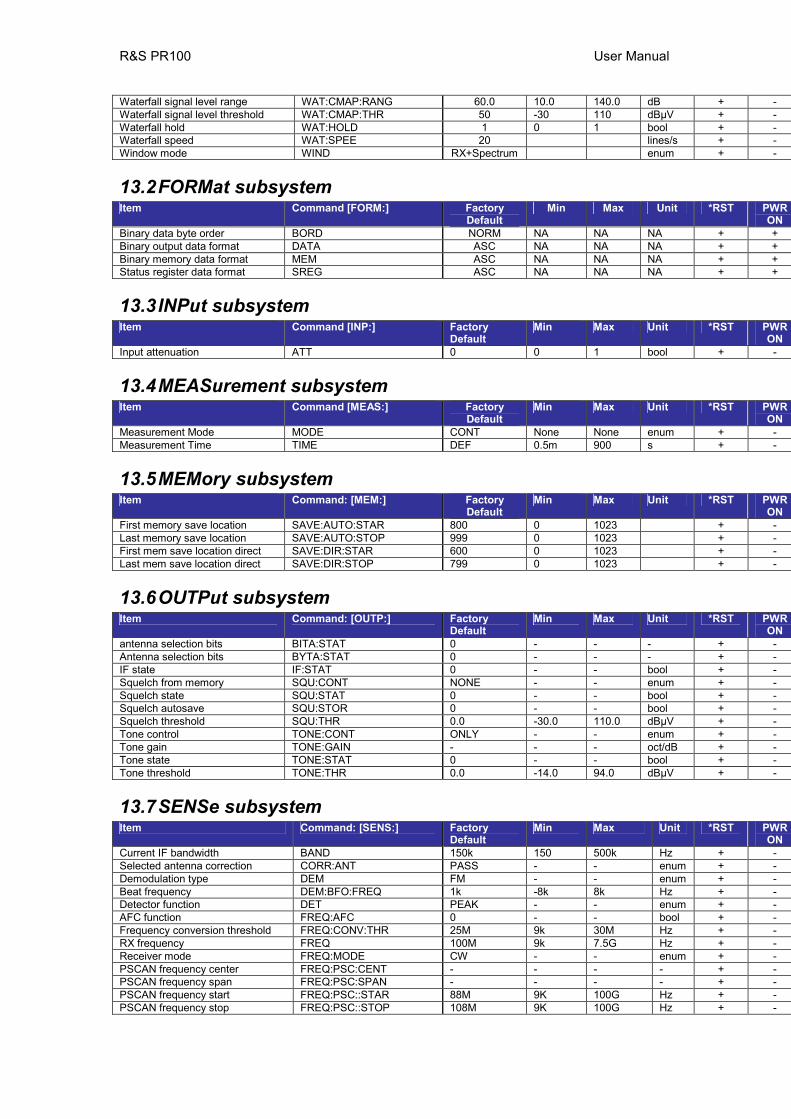
R&S PR100 User Manual
Waterfall signal level range WAT:CMAP:RANG 60.0 10.0 140.0 dB + - Waterfall signal level threshold WAT:CMAP:THR 50 -30 110 dBµV + - Waterfall hold WAT:HOLD 1 0 1 bool + - Waterfall speed WAT:SPEE 20 lines/s + - Window mode WIND RX+Spectrum enum + -
13.2 FORMat subsystem Item Command [FORM:] Factory
Default Min Max Unit *RST PWR
ON Binary data byte order BORD NORM NA NA NA + + Binary output data format DATA ASC NA NA NA + + Binary memory data format MEM ASC NA NA NA + + Status register data format SREG ASC NA NA NA + +
13.3 INPut subsystem Item Command [INP:] Factory
Default Min Max Unit *RST PWR
ON Input attenuation ATT 0 0 1 bool + -
13.4 MEASurement subsystem Item Command [MEAS:] Factory
Default Min Max Unit *RST PWR
ON Measurement Mode MODE CONT None None enum + - Measurement Time TIME DEF 0.5m 900 s + -
13.5 MEMory subsystem Item Command: [MEM:] Factory
Default Min Max Unit *RST PWR
ON First memory save location SAVE:AUTO:STAR 800 0 1023 + - Last memory save location SAVE:AUTO:STOP 999 0 1023 + - First mem save location direct SAVE:DIR:STAR 600 0 1023 + - Last mem save location direct SAVE:DIR:STOP 799 0 1023 + -
13.6 OUTPut subsystem Item Command: [OUTP:] Factory
Default Min Max Unit *RST PWR
ON antenna selection bits BITA:STAT 0 - - - + - Antenna selection bits BYTA:STAT 0 - - - + - IF state IF:STAT 0 - - bool + - Squelch from memory SQU:CONT NONE - - enum + - Squelch state SQU:STAT 0 - - bool + - Squelch autosave SQU:STOR 0 - - bool + - Squelch threshold SQU:THR 0.0 -30.0 110.0 dBµV + - Tone control TONE:CONT ONLY - - enum + - Tone gain TONE:GAIN - - - oct/dB + - Tone state TONE:STAT 0 - - bool + - Tone threshold TONE:THR 0.0 -14.0 94.0 dBµV + -
13.7 SENSe subsystem Item Command: [SENS:] Factory
Default Min Max Unit *RST PWR
ON Current IF bandwidth BAND 150k 150 500k Hz + - Selected antenna correction CORR:ANT PASS - - enum + - Demodulation type DEM FM - - enum + - Beat frequency DEM:BFO:FREQ 1k -8k 8k Hz + - Detector function DET PEAK - - enum + - AFC function FREQ:AFC 0 - - bool + - Frequency conversion threshold FREQ:CONV:THR 25M 9k 30M Hz + - RX frequency FREQ 100M 9k 7.5G Hz + - Receiver mode FREQ:MODE CW - - enum + - PSCAN frequency center FREQ:PSC:CENT - - - - + - PSCAN frequency span FREQ:PSC:SPAN - - - - + - PSCAN frequency start FREQ:PSC::STAR 88M 9K 100G Hz + - PSCAN frequency stop FREQ:PSC::STOP 108M 9K 100G Hz + -
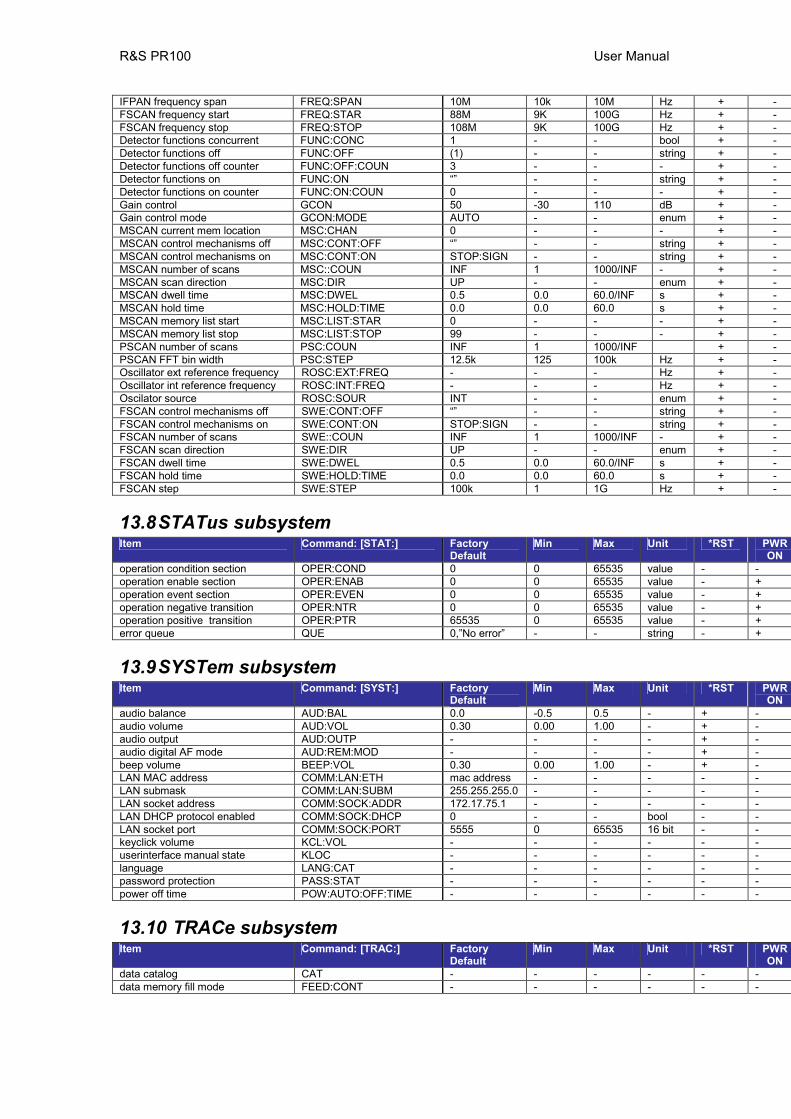
R&S PR100 User Manual
IFPAN frequency span FREQ:SPAN 10M 10k 10M Hz + - FSCAN frequency start FREQ:STAR 88M 9K 100G Hz + - FSCAN frequency stop FREQ:STOP 108M 9K 100G Hz + - Detector functions concurrent FUNC:CONC 1 - - bool + - Detector functions off FUNC:OFF (1) - - string + - Detector functions off counter FUNC:OFF:COUN 3 - - - + - Detector functions on FUNC:ON “” - - string + - Detector functions on counter FUNC:ON:COUN 0 - - - + - Gain control GCON 50 -30 110 dB + - Gain control mode GCON:MODE AUTO - - enum + - MSCAN current mem location MSC:CHAN 0 - - - + - MSCAN control mechanisms off MSC:CONT:OFF “” - - string + - MSCAN control mechanisms on MSC:CONT:ON STOP:SIGN - - string + - MSCAN number of scans MSC::COUN INF 1 1000/INF - + - MSCAN scan direction MSC:DIR UP - - enum + - MSCAN dwell time MSC:DWEL 0.5 0.0 60.0/INF s + - MSCAN hold time MSC:HOLD:TIME 0.0 0.0 60.0 s + - MSCAN memory list start MSC:LIST:STAR 0 - - - + - MSCAN memory list stop MSC:LIST:STOP 99 - - - + - PSCAN number of scans PSC:COUN INF 1 1000/INF + - PSCAN FFT bin width PSC:STEP 12.5k 125 100k Hz + - Oscillator ext reference frequency ROSC:EXT:FREQ - - - Hz + - Oscillator int reference frequency ROSC:INT:FREQ - - - Hz + - Oscilator source ROSC:SOUR INT - - enum + - FSCAN control mechanisms off SWE:CONT:OFF “” - - string + - FSCAN control mechanisms on SWE:CONT:ON STOP:SIGN - - string + - FSCAN number of scans SWE::COUN INF 1 1000/INF - + - FSCAN scan direction SWE:DIR UP - - enum + - FSCAN dwell time SWE:DWEL 0.5 0.0 60.0/INF s + - FSCAN hold time SWE:HOLD:TIME 0.0 0.0 60.0 s + - FSCAN step SWE:STEP 100k 1 1G Hz + -
13.8 STATus subsystem Item Command: [STAT:] Factory
Default Min Max Unit *RST PWR
ON operation condition section OPER:COND 0 0 65535 value - - operation enable section OPER:ENAB 0 0 65535 value - + operation event section OPER:EVEN 0 0 65535 value - + operation negative transition OPER:NTR 0 0 65535 value - + operation positive transition OPER:PTR 65535 0 65535 value - + error queue QUE 0,”No error” - - string - +
13.9 SYSTem subsystem Item Command: [SYST:] Factory
Default Min Max Unit *RST PWR
ON audio balance AUD:BAL 0.0 -0.5 0.5 - + - audio volume AUD:VOL 0.30 0.00 1.00 - + - audio output AUD:OUTP - - - - + - audio digital AF mode AUD:REM:MOD - - - - + - beep volume BEEP:VOL 0.30 0.00 1.00 - + - LAN MAC address COMM:LAN:ETH mac address - - - - - LAN submask COMM:LAN:SUBM 255.255.255.0 - - - - - LAN socket address COMM:SOCK:ADDR 172.17.75.1 - - - - - LAN DHCP protocol enabled COMM:SOCK:DHCP 0 - - bool - - LAN socket port COMM:SOCK:PORT 5555 0 65535 16 bit - - keyclick volume KCL:VOL - - - - - - userinterface manual state KLOC - - - - - - language LANG:CAT - - - - - - password protection PASS:STAT - - - - - - power off time POW:AUTO:OFF:TIME - - - - - -
13.10 TRACe subsystem Item Command: [TRAC:] Factory
Default Min Max Unit *RST PWR
ON data catalog CAT - - - - - - data memory fill mode FEED:CONT - - - - - -