presentation -9 - iit kanpurhome.iitk.ac.in/~sarv/new folder/presentation -9.pdftunnel support...
TRANSCRIPT
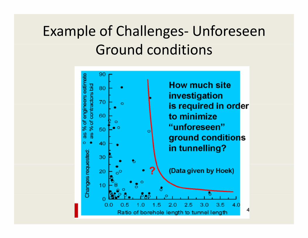
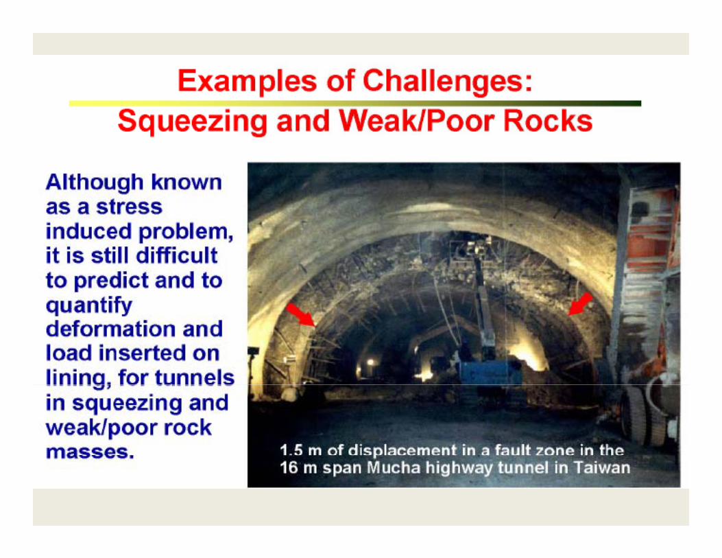
Example of Challenges‐ Unforeseen d dGround conditions
Rock Mass Rating SystemsRock Mass Rating Systems
ROCK MASS RATING SYSTEM RMRor RMR
Bieniawski (1972)
‐ numerous amendments since
For assessing the stability of rock slopesFor assessing the stability of rock slopes
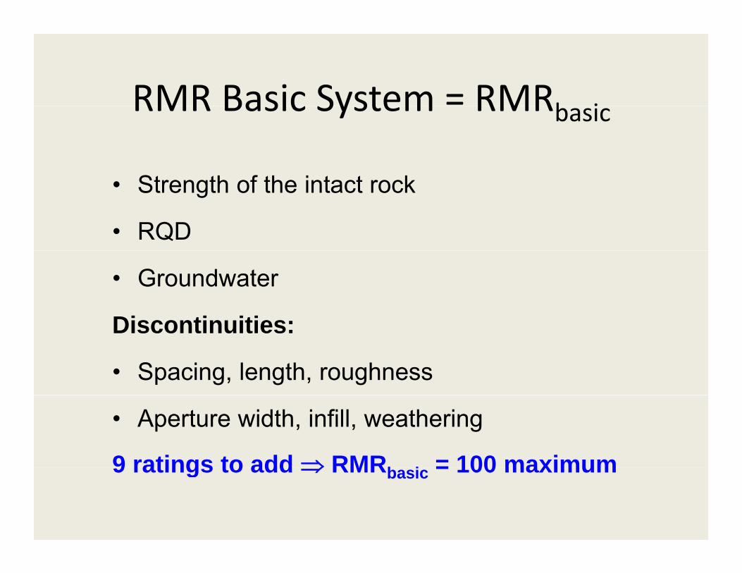
RMR Basic System = RMRb iRMR Basic System RMRbasic
St th f th i t t k• Strength of the intact rock
• RQD
• Groundwater
Discontinuities:Discontinuities:
• Spacing, length, roughness
• Aperture width, infill, weathering
9 ratings to add ⇒ RMRb i = 100 maximum9 ratings to add ⇒ RMRbasic = 100 maximum
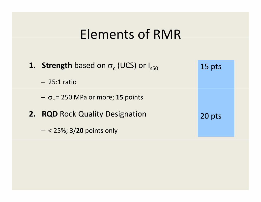
Elements of RMRElements of RMR
1 S h b d (UCS) I1. Strength based on σc (UCS) or Is50
– 25:1 ratio
15 pts
– σc = 250 MPa or more; 15 points
2 RQD Rock Quality Designation 20 t2. RQD Rock Quality Designation
– < 25%; 3/20 points only
20 pts
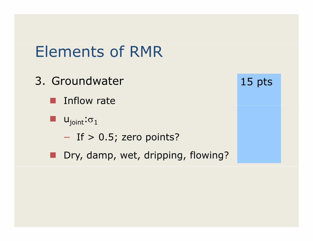
Elements of RMR
3. Groundwater
Inflow rate
15 pts
ujoint:σ1
If > 0 5; zero points?− If > 0.5; zero points?
Dry, damp, wet, dripping, flowing?
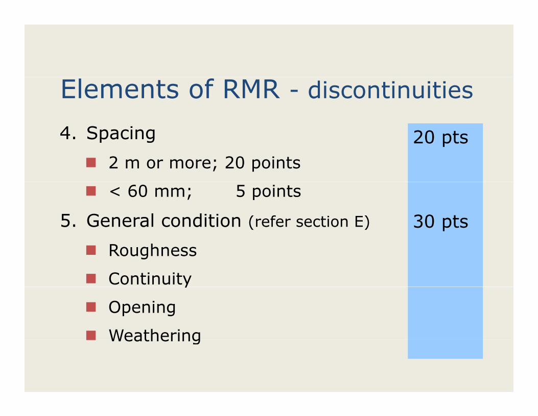
Elements of RMR - discontinuities
4 Spacing4. Spacing
2 m or more; 20 points
20 pts
< 60 mm; 5 points
5. General condition (refer section E) 30 pts
Roughness
Continuityy
Opening
WeatheringWeathering
RMR modified for slopes or tunnelsRMR modified for slopes or tunnels
Additional factors applied to RMRbasic
• Accounts for excavation methodAccounts for excavation method
BUT moreover,
A t f j i t i t ti t th ti• Accounts for joint orientation wrt the excavation
– Unfavourable conditions, deduct points from RMRRMRbasic
– refer section F of Table
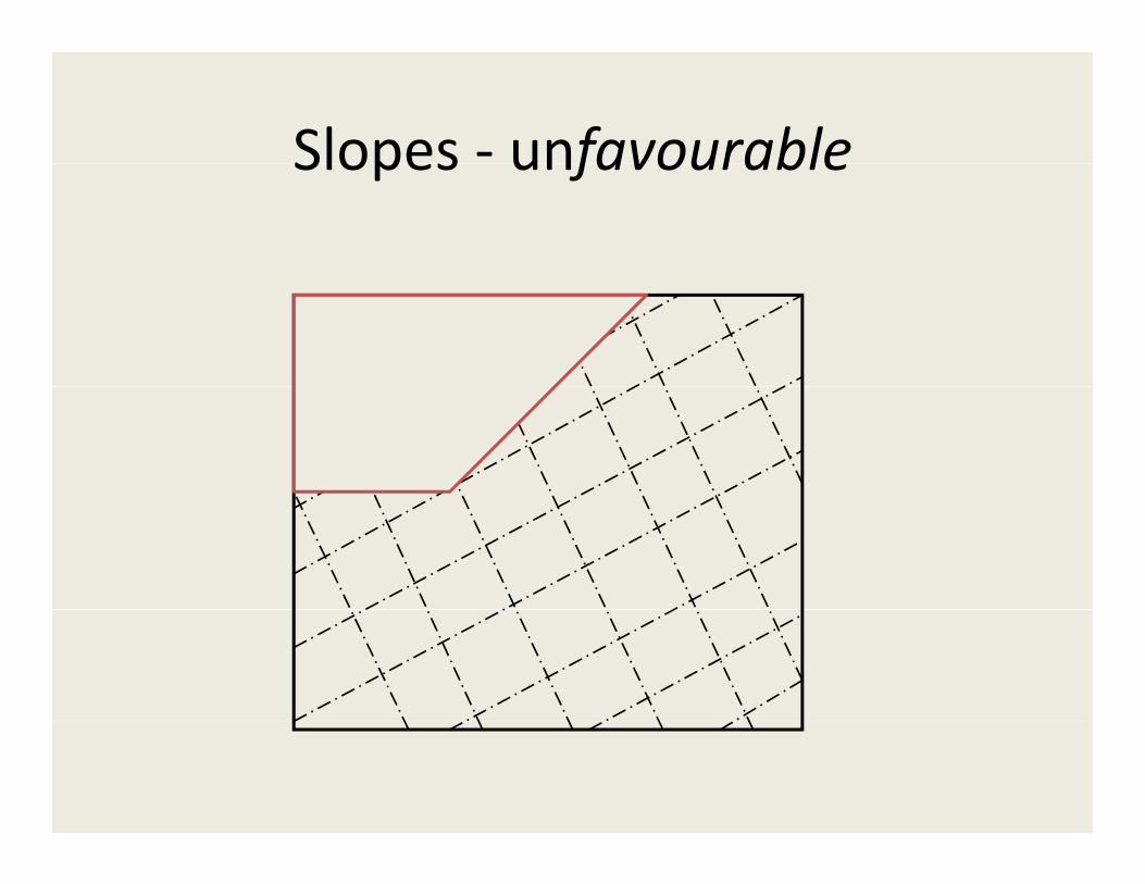
Slopes ‐ unfavourableSlopes unfavourable
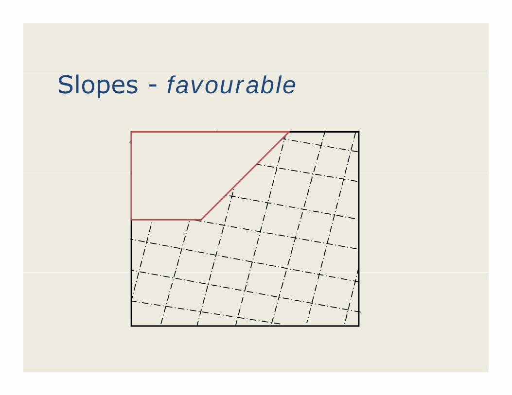
Slopes - favourable
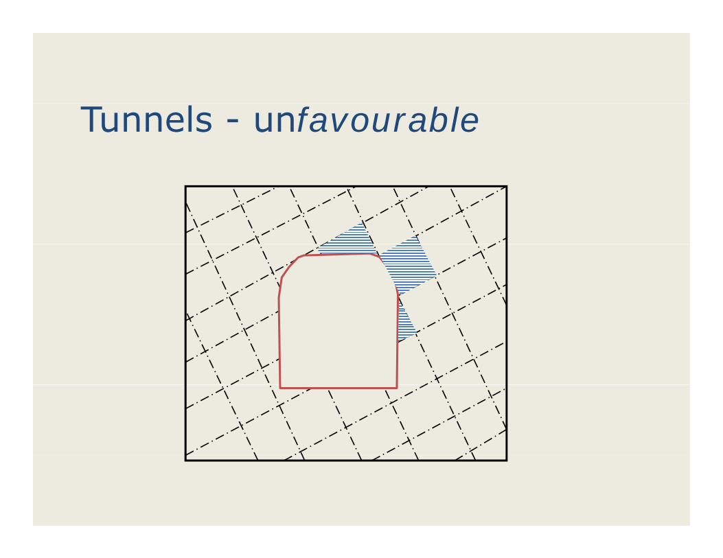
Tunnels - unfavourable

Tunnels - favourable• Widely spaced joints?Widely spaced joints?
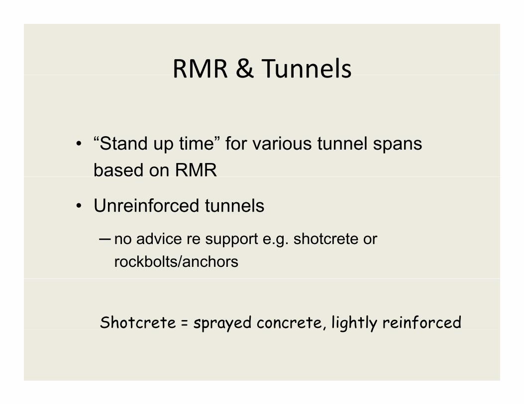
RMR & TunnelsRMR & Tunnels
• “Stand up time” for various tunnel spans based on RMR
• Unreinforced tunnels
─ no advice re support e.g. shotcrete or rockbolts/anchors
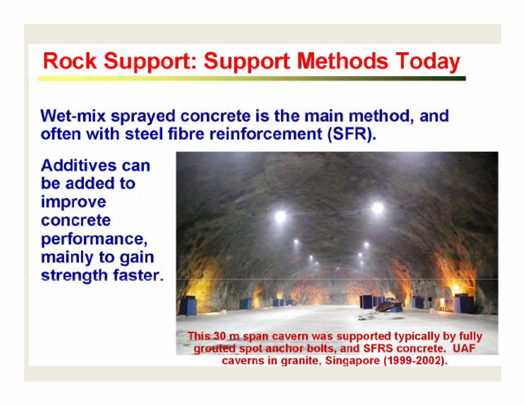
Shotcrete = sprayed concrete, lightly reinforcedp y , g y
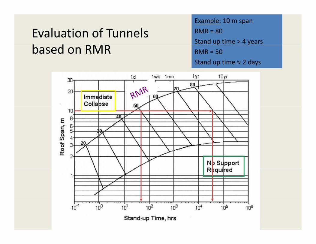
Evaluation of Tunnels b d RMR
Example: 10 m span
RMR = 80
Stand up time > 4 yearsbased on RMR RMR = 50
Stand up time ≈ 2 days
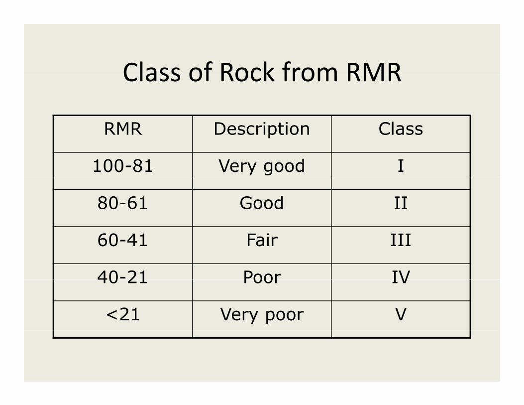
Class of Rock from RMRClass of Rock from RMR
RMR Description ClassRMR Description Class
100-81 Very good I
80-61 Good II
60-41 Fair III
40-21 Poor IV40 21 Poor IV
<21 Very poor V

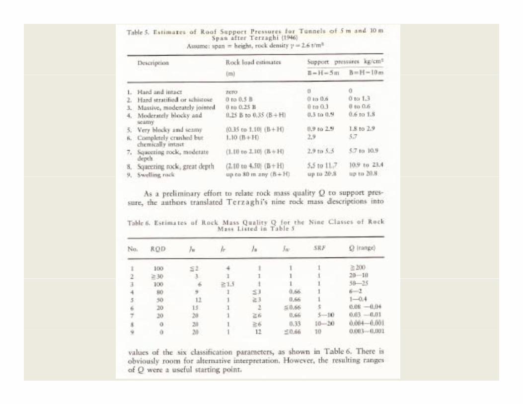
An Alternative Rating SystemAn Alternative Rating System
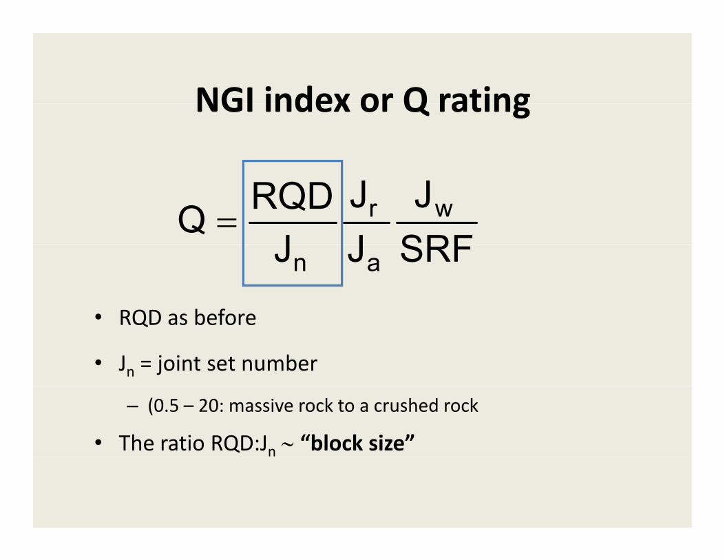
NGI index or Q ratingNGI index or Q rating
SRFJ
JJ
JRQDQ wr=
SRFJJ an
• RQD as before• RQD as before
• Jn = joint set number
– (0.5 – 20: massive rock to a crushed rock
• The ratio RQD:Jn ∼ “block size”
Q System
SRFJ
JJ
JRQDQ wr=
SRFJJ an
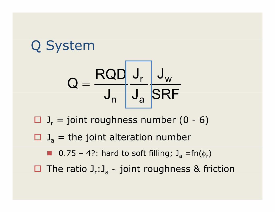
J = joint roughness number (0 6)Jr = joint roughness number (0 - 6)
Ja = the joint alteration number
0.75 – 4?: hard to soft filling; Ja =fn(φr)
The ratio Jr:Ja ∼ joint roughness & frictionr a j g
Q System
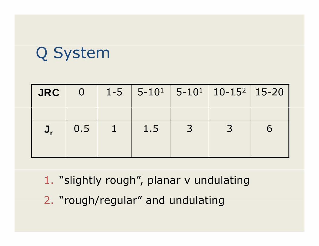
JRC 0 1-5 5-101 5-101 10-152 15-20
Jr 0.5 1 1.5 3 3 6
1. “slightly rough”, planar v undulating
2 “rough/regular” and undulating2. rough/regular and undulating
Q System
SRFJ
JJ
JRQDQ wr=
SRFJJ an
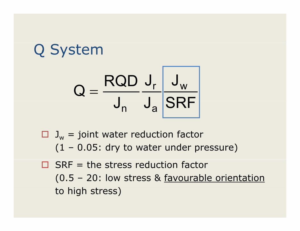
Jw = joint water reduction factor (1 – 0.05: dry to water under pressure)
SRF = the stress reduction factor (0.5 – 20: low stress & favourable orientationt hi h t )to high stress)
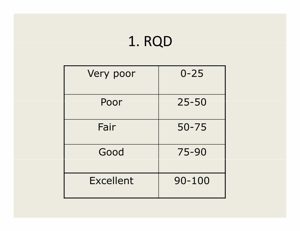
1 RQD1. RQD
Very poor 0 25Very poor 0-25
Poor 25 50Poor 25-50
Fair 50-75Fair 50 75
Good 75-90
Excellent 90-100
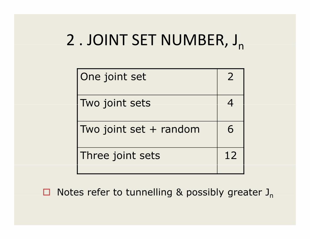
2 . JOINT SET NUMBER, Jn2 . JOINT SET NUMBER, Jn
O j i t t 2One joint set 2
Two joint sets 4Two joint sets 4
Two joint set + random 6j
Three joint sets 12
Notes refer to tunnelling & possibly greater JnNotes refer to tunnelling & possibly greater Jn
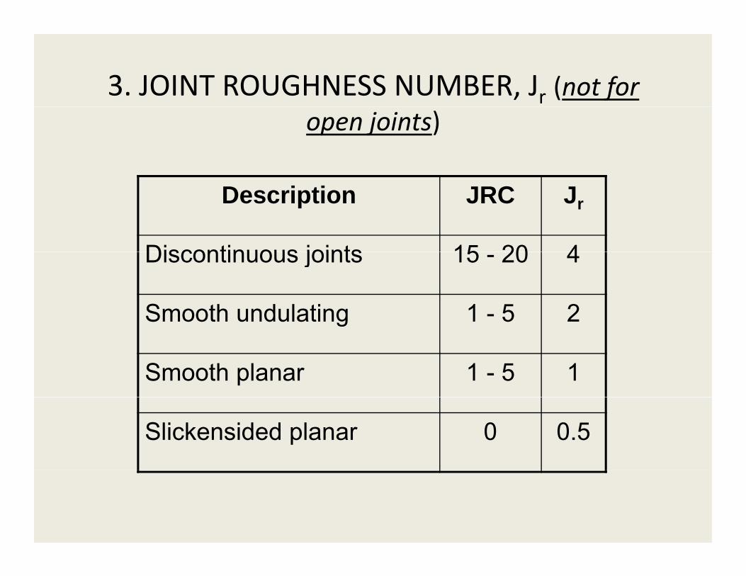
3. JOINT ROUGHNESS NUMBER, Jr (not for open joints)
Description JRC Jr
Discontinuous joints 15 20 4Discontinuous joints 15 - 20 4
Smooth undulating 1 - 5 2g
Smooth planar 1 - 5 1
Slickensided planar 0 0.5
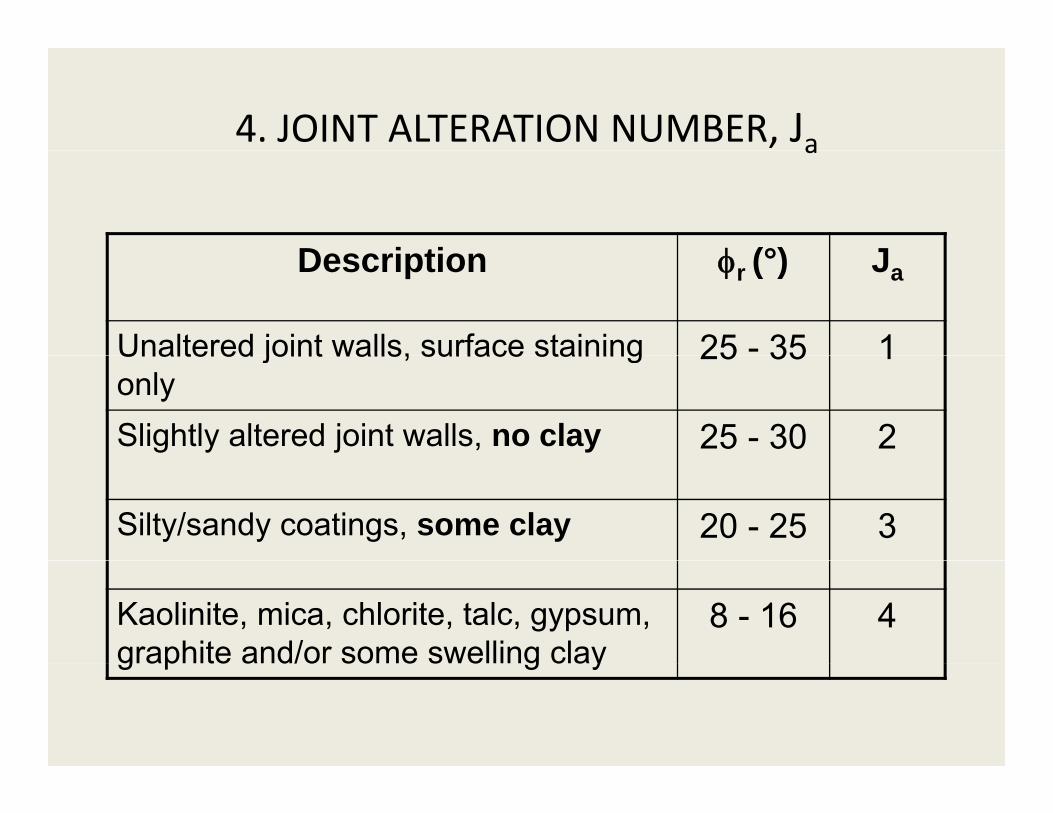
4. JOINT ALTERATION NUMBER, Jaa
D i ti φ (°) JDescription φr (°) Ja
Unaltered joint walls, surface staining 25 - 35 1Unaltered joint walls, surface staining only
25 35 1
Slightly altered joint walls, no clay 25 - 30 2
Silty/sandy coatings, some clay 20 - 25 3
Kaolinite, mica, chlorite, talc, gypsum, graphite and/or some swelling clay
8 - 16 4graphite and/or some swelling clay
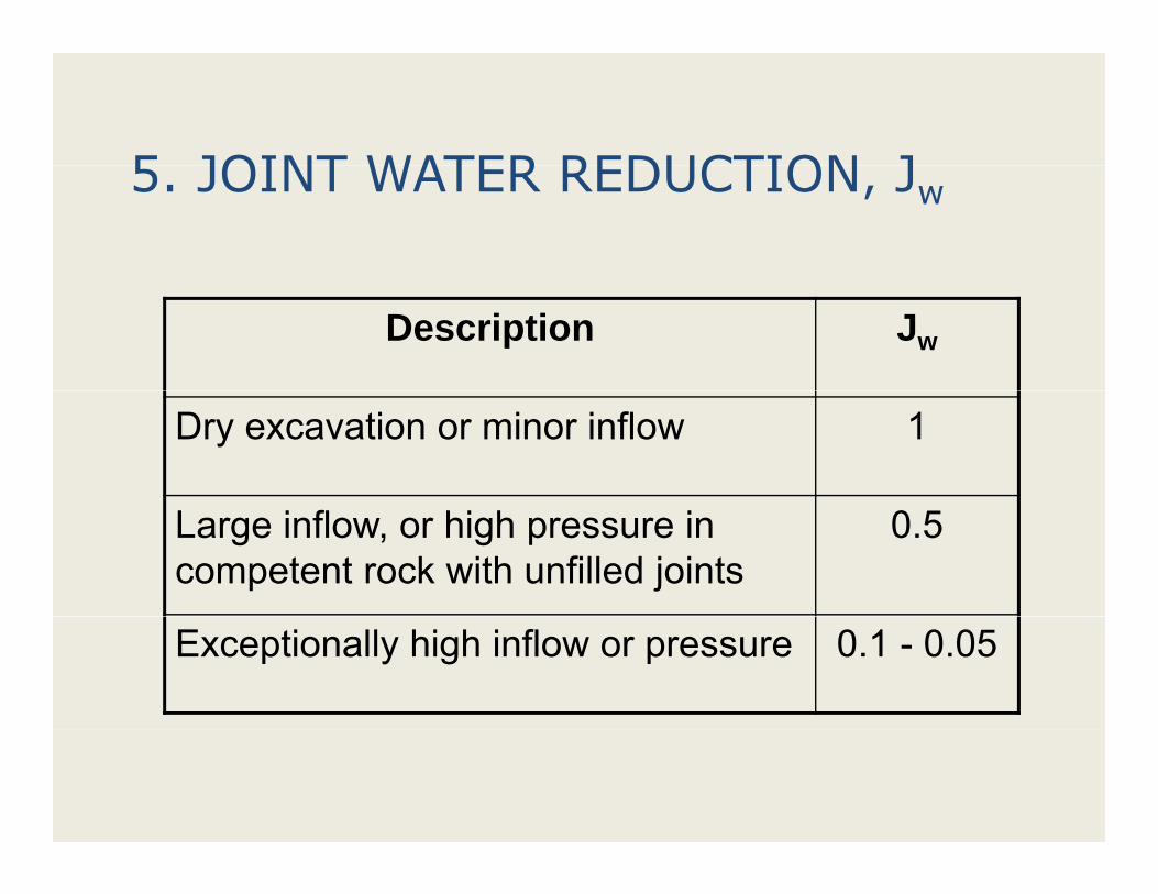
5 JOINT WATER REDUCTION J5. JOINT WATER REDUCTION, Jw
Description Jw
Dry excavation or minor inflow 1
Large inflow, or high pressure in competent rock with unfilled joints
0.5
Exceptionally high inflow or pressure 0.1 - 0.05
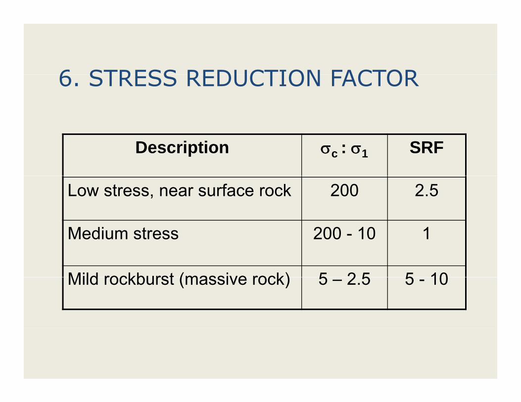
6 STRESS REDUCTION FACTOR6. STRESS REDUCTION FACTOR
Description σc : σ1 SRF
Low stress, near surface rock 200 2.5
Medium stress 200 - 10 1
Mild rockburst (massive rock) 5 2 5 5 10Mild rockburst (massive rock) 5 – 2.5 5 - 10
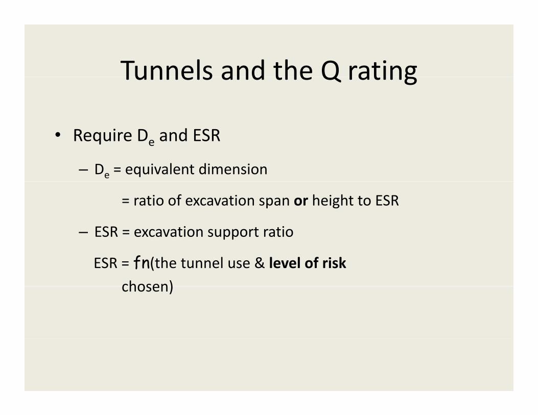
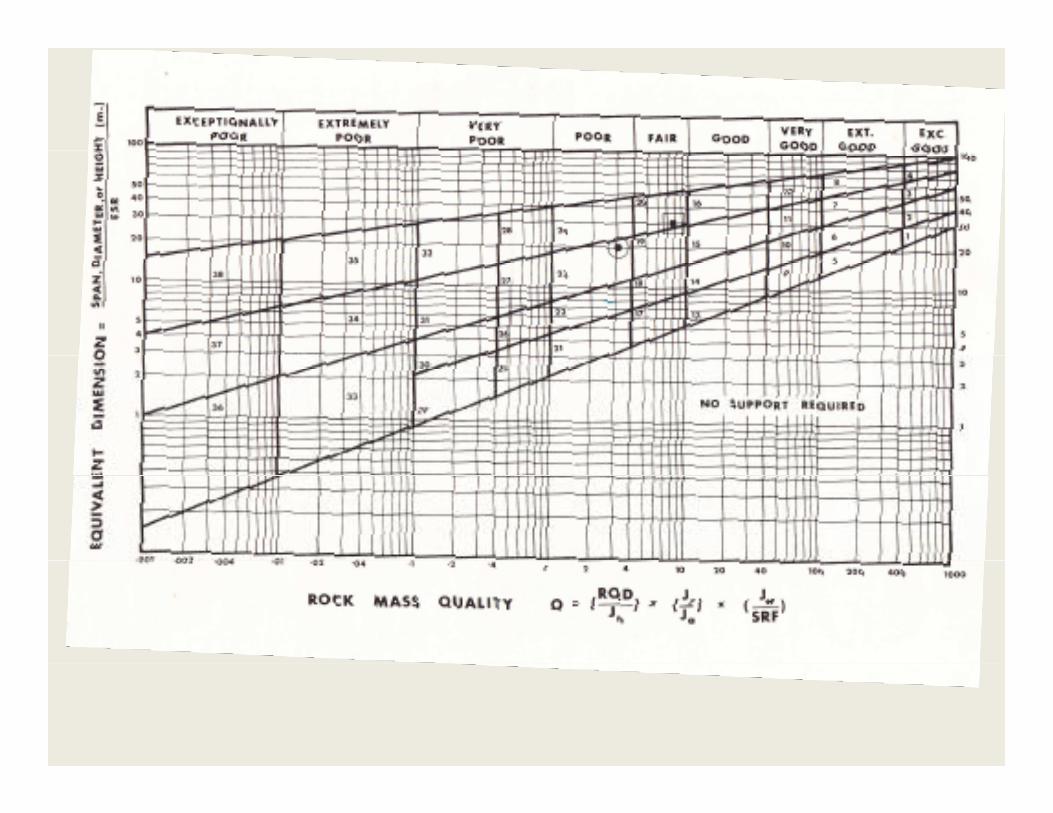
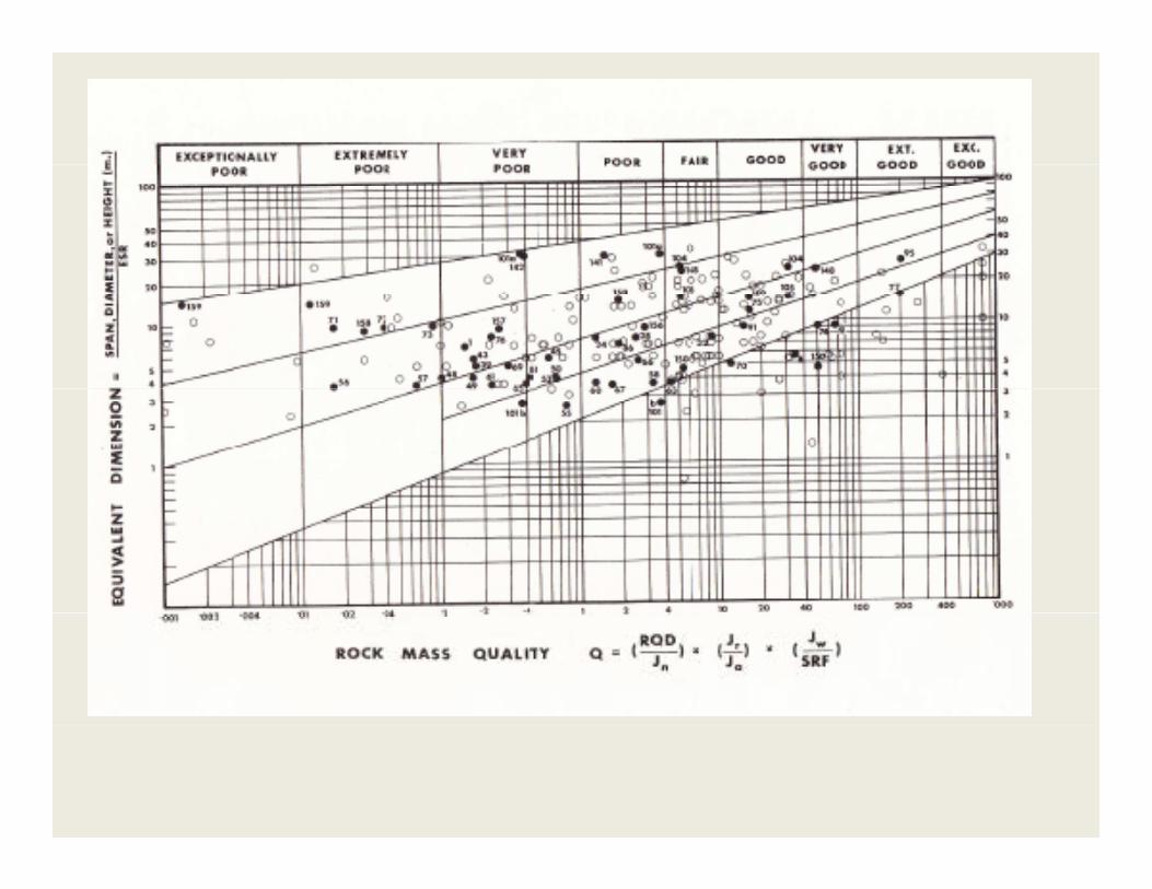
Tunnels and the Q ratingTunnels and the Q rating
R i D d ESR• Require De and ESR
– De = equivalent dimension
= ratio of excavation span or height to ESR
– ESR = excavation support ratioESR = excavation support ratio
ESR = fn(the tunnel use & level of riskchosen)chosen)
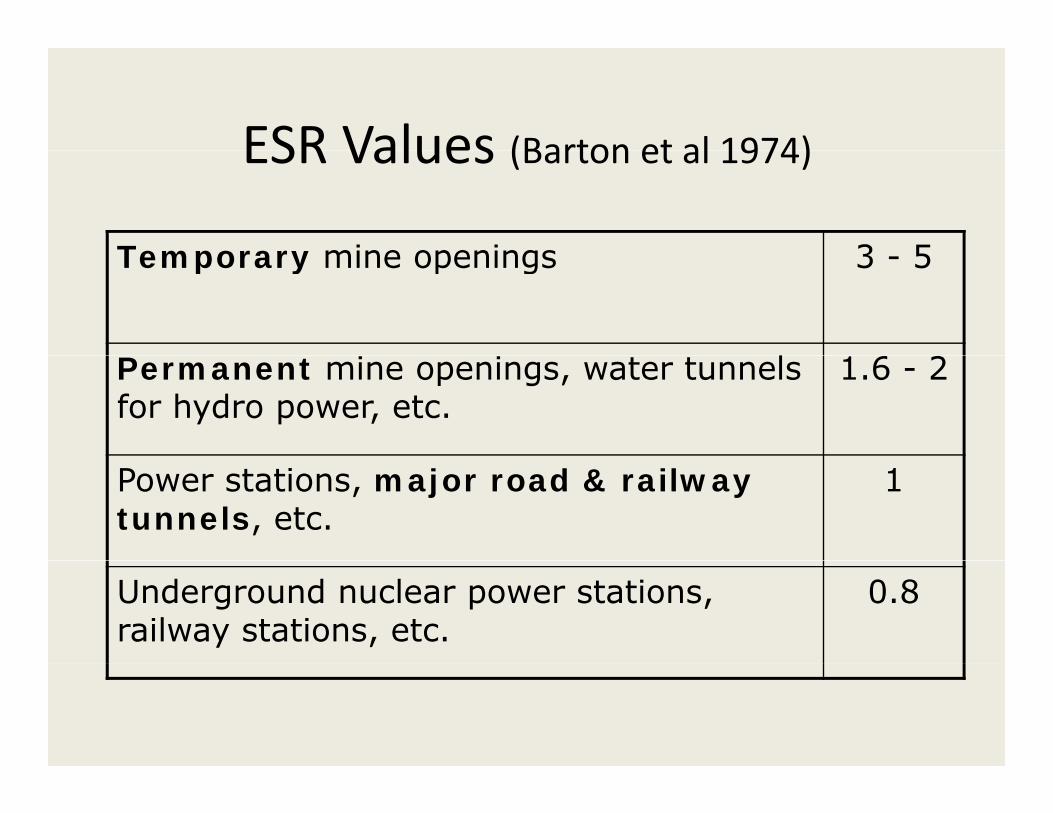
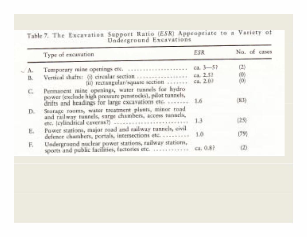
ESR Values (Barton et al 1974)ESR Values (Barton et al 1974)
Temporary mine openings 3 5Temporary mine openings 3 - 5
lPermanent mine openings, water tunnels for hydro power, etc.
1.6 - 2
Power stations, major road & railway tunnels, etc.
1
Underground nuclear power stations, railway stations, etc.
0.8
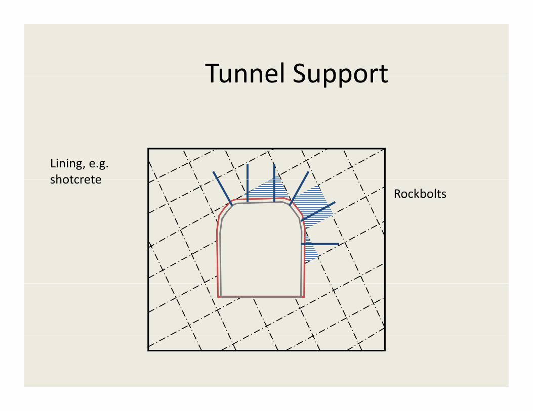
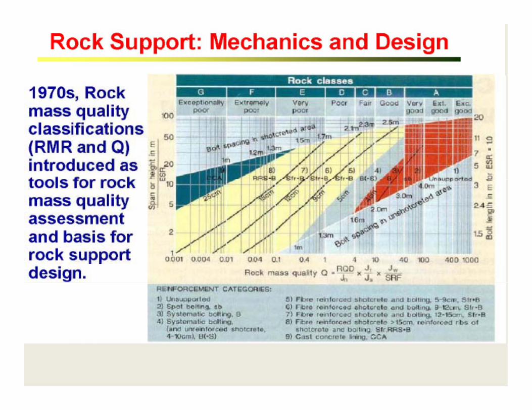
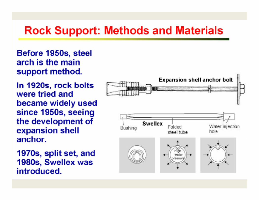
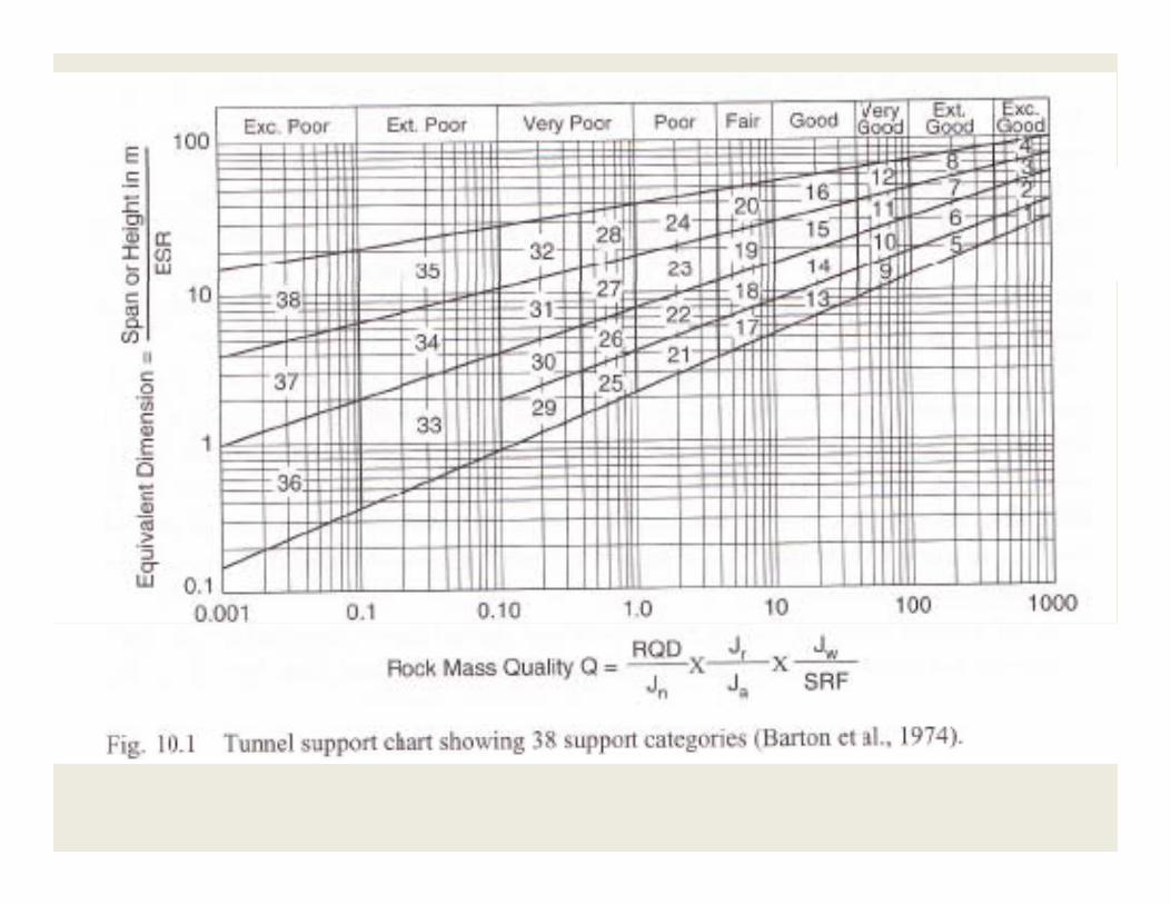
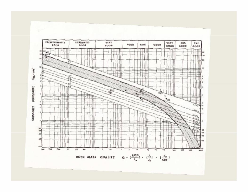
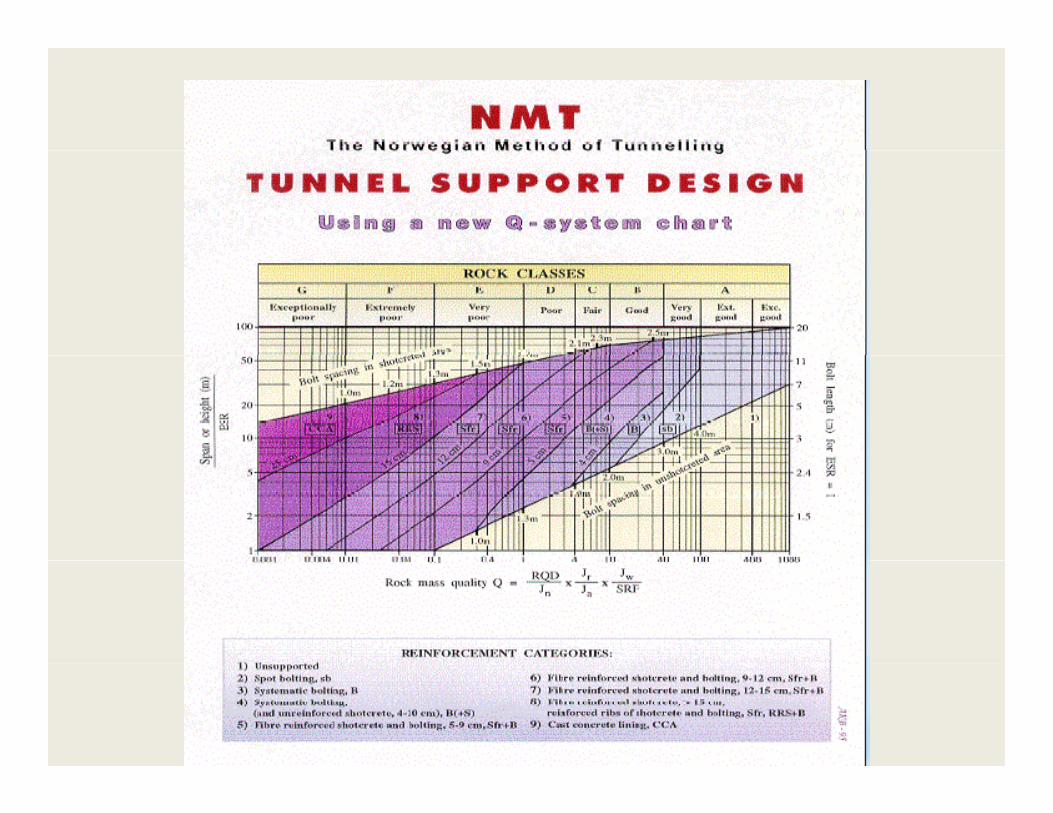
Tunnel SupportTunnel Support
Lining, e.g. shotcreteshotcrete
Rockbolts
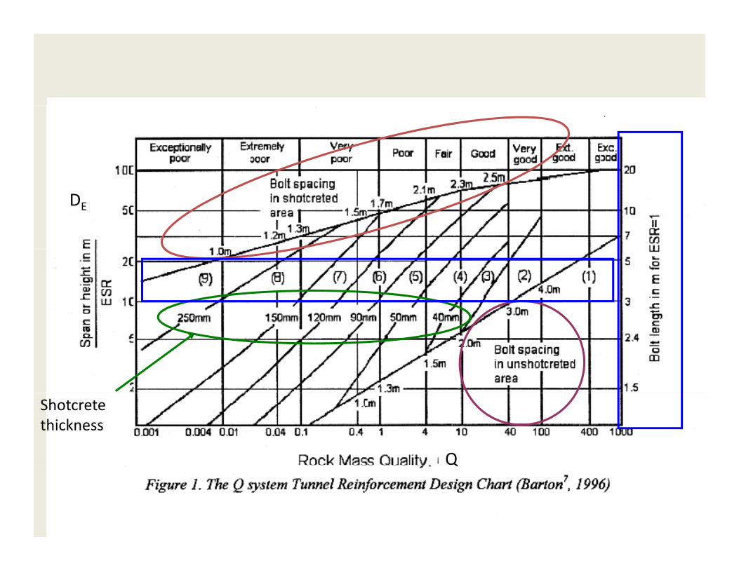
DE
Q
Shotcrete thickness
Q
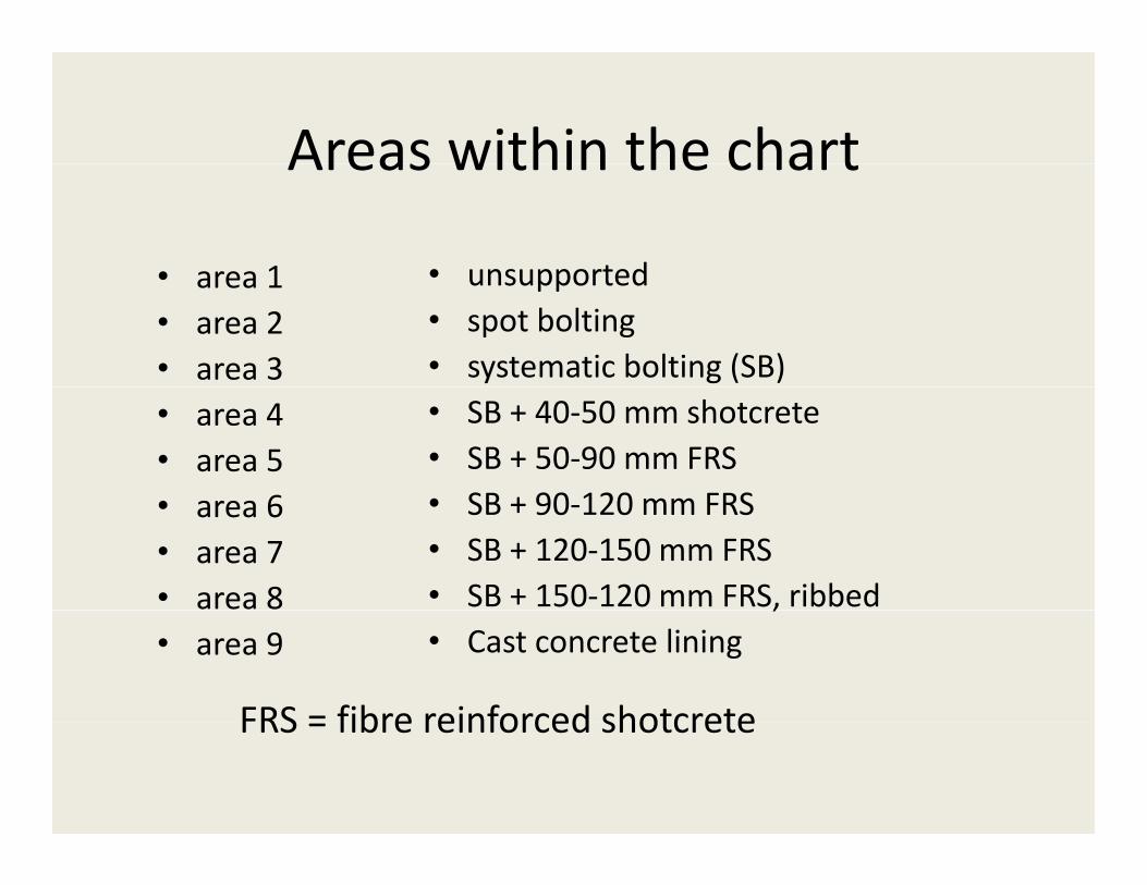
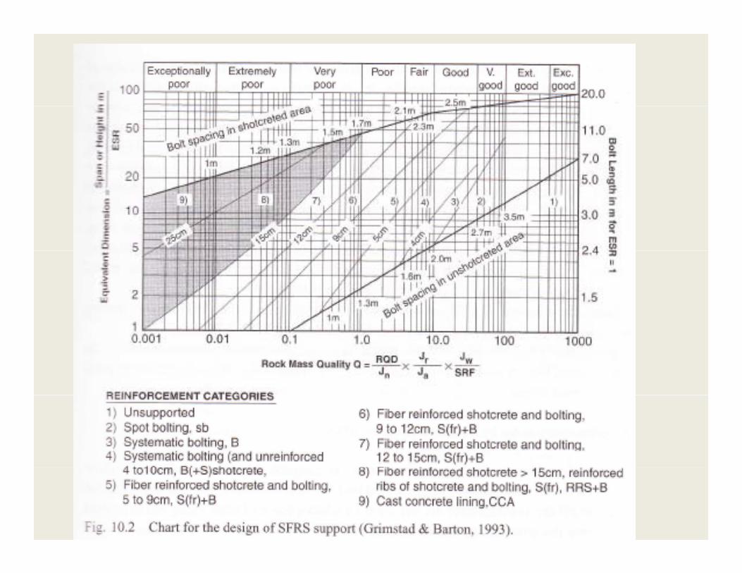
Areas within the chartAreas within the chart
• area 1 • unsupported• area 1• area 2• area 3
• unsupported• spot bolting• systematic bolting (SB)
• area 4• area 5
6
• SB + 40‐50 mm shotcrete• SB + 50‐90 mm FRS• SB + 90 120 mm FRS• area 6
• area 7• area 8
• SB + 90‐120 mm FRS• SB + 120‐150 mm FRS• SB + 150‐120 mm FRS, ribbed
• area 9,
• Cast concrete lining
FRS = fibre reinforced shotcreteFRS = fibre reinforced shotcrete
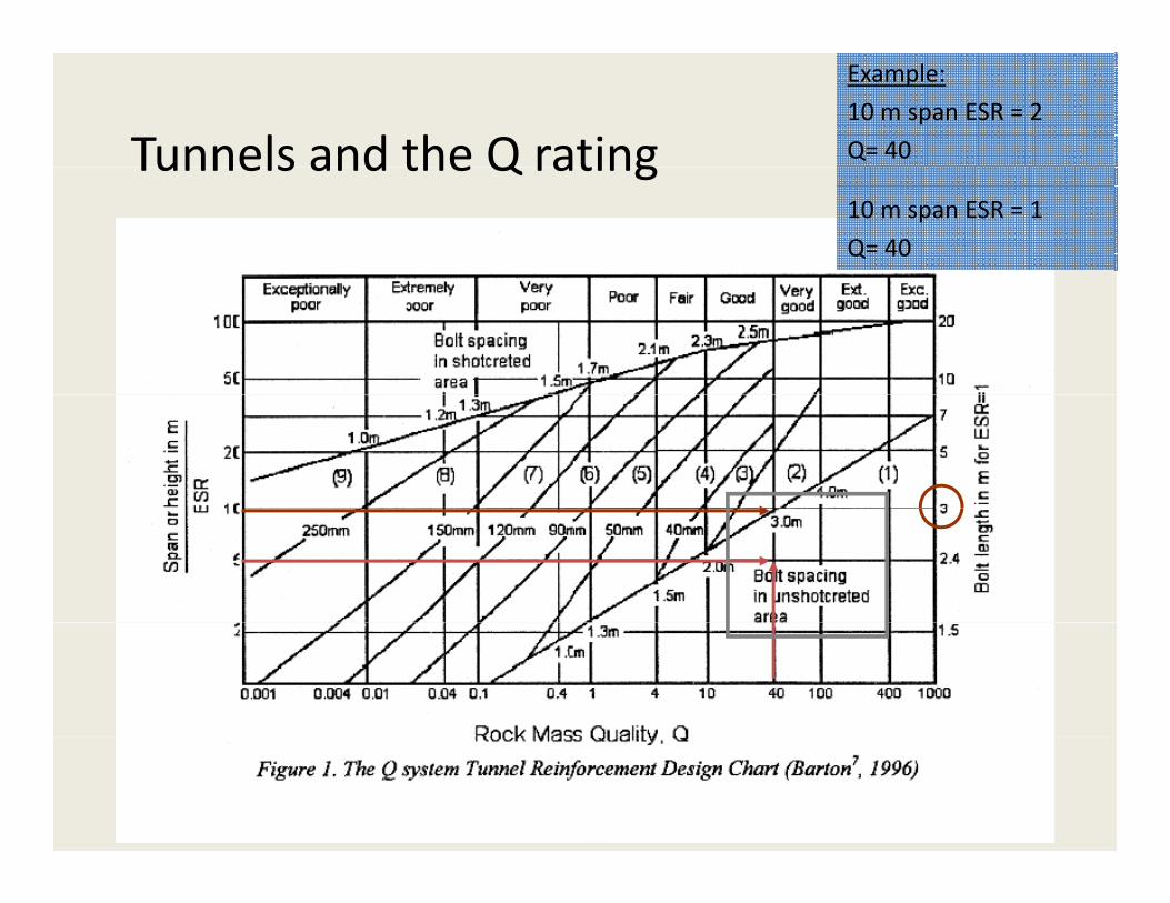
Tunnels and the Q rating
Example:
10 m span ESR = 2
Q= 40Tunnels and the Q rating10 m span ESR = 1
Q= 40
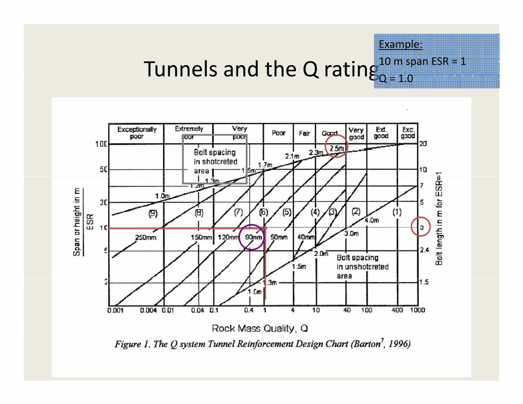
Tunnels and the Q ratingExample:
10 m span ESR = 1
Q 1 0Tunnels and the Q ratingQ = 1.0
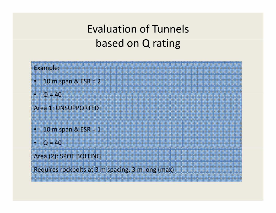
Evaluation of Tunnels b d Q ibased on Q rating
E lExample:
• 10 m span & ESR = 2
Q 40• Q = 40
Area 1: UNSUPPORTED
• 10 m span & ESR = 1
• Q = 40
Area (2): SPOT BOLTING
Requires rockbolts at 3 m spacing, 3 m long (max)

Draft Layout Guidance for DUSELLaughton, February 2006
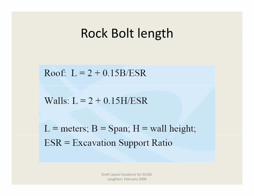
Rock Bolt lengthRock Bolt length
Draft Layout Guidance for DUSELLaughton, February 2006
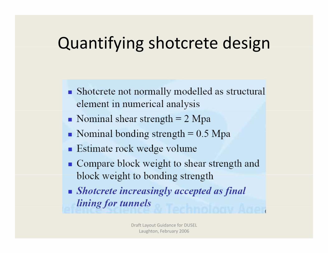
Quantifying shotcrete designQuantifying shotcrete design
Draft Layout Guidance for DUSELLaughton, February 2006
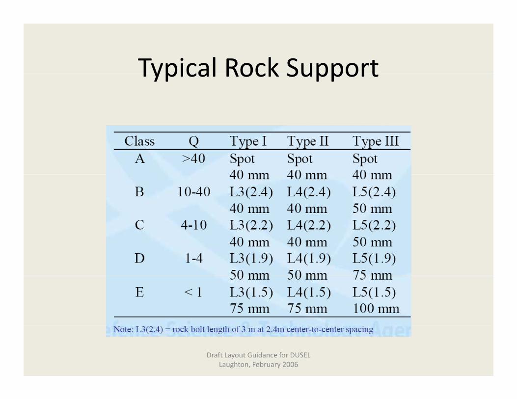
Typical Rock SupportTypical Rock Support
Draft Layout Guidance for DUSELLaughton, February 2006

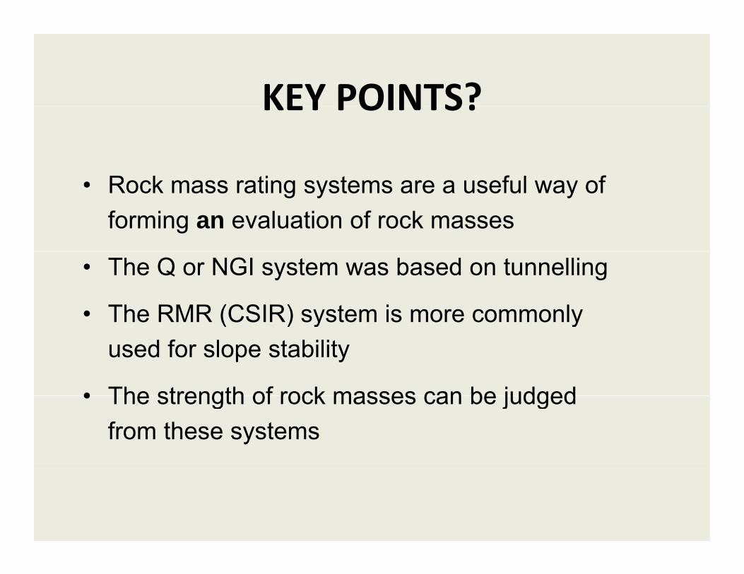
KEY POINTS?KEY POINTS?
R k ti t f l f• Rock mass rating systems are a useful way of forming an evaluation of rock masses
• The Q or NGI system was based on tunnelling
• The RMR (CSIR) system is more commonly ( ) y yused for slope stability
• The strength of rock masses can be judged• The strength of rock masses can be judged from these systems