processing elements design - 國立臺灣大學
TRANSCRIPT

1
Processing
Elements Design
Shao-Yi Chien

DSP in VLSI Design Shao-Yi Chien 2
Introduction Implementation of basic arithmetic operations
Number systems
Conventional number systems
Redundant number systems
Residue number systems
Arithmetic
Bit-parallel arithmetic
Bit-serial arithmetic
Serial-parallel arithmetic
Division
Distributed arithmetic
CORDIC

DSP in VLSI Design Shao-Yi Chien 3
Conventional Number Systems
Conventional number systems are nonredundant, weighted, positional number systems
Fix-point: the position of binary point is fixed
Floating point: signed mantissa and signed exponent
Nonredundant: one number has only one representation
Wd: word length
wi: weightsweighted
wi depends only on the position of the digitpositional
For fix-radix systems, wi=ri

DSP in VLSI Design Shao-Yi Chien 4
Signed-Magnitude
Representation Range
[-1+Q, 1-Q]
Q=(0.00..01)
Complex for addition and subtraction
Easy for multiplication and division

DSP in VLSI Design Shao-Yi Chien 5
One’s Complement
Range
[-1+Q, 1-Q]
Change sign is
easy
Addition,
subtraction, and
multiplication are
complex
DSP in VLSI Design Shao-Yi Chien 6
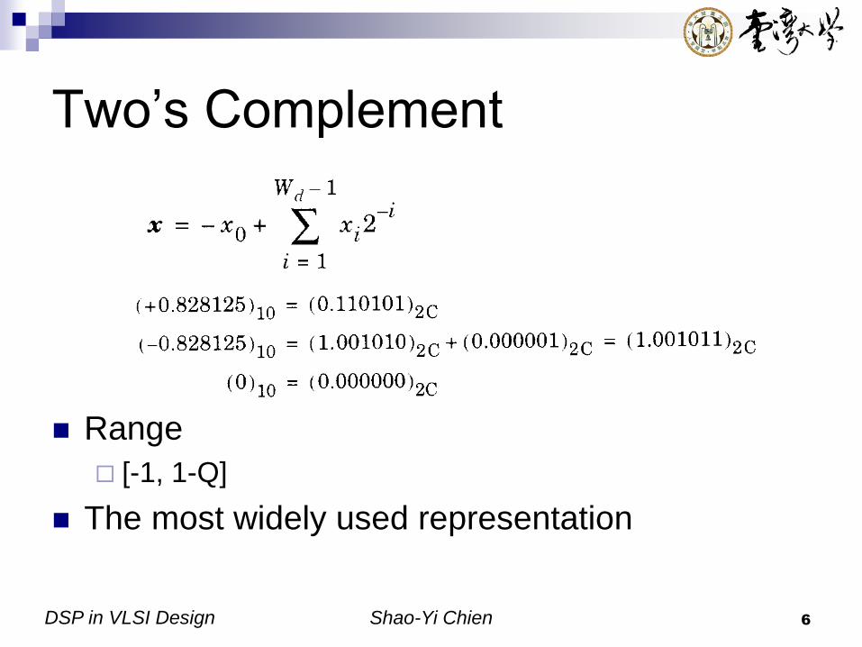
Two’s Complement
Range
[-1, 1-Q]
The most widely used representation
DSP in VLSI Design Shao-Yi Chien 7
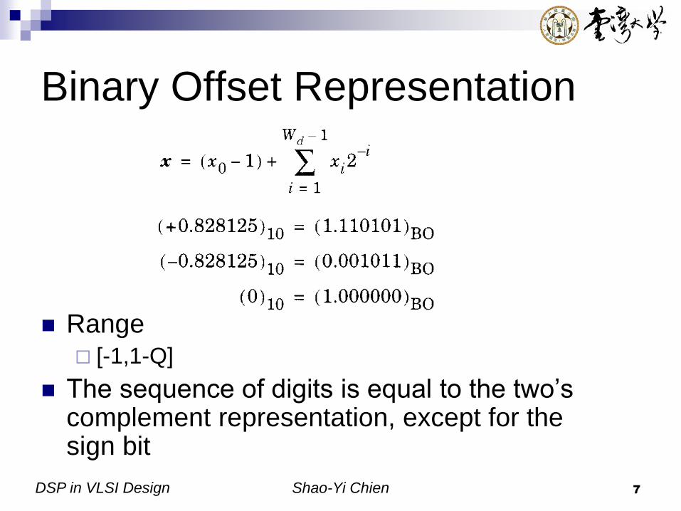
Binary Offset Representation
Range [-1,1-Q]
The sequence of digits is equal to the two’s complement representation, except for the sign bit

DSP in VLSI Design Shao-Yi Chien 8
Redundant Number Systems
(1/2) Redundant: one number has more than one
representation
Advantages Simply and speed up certain arithmetic operation
Addition and subtraction can be performed without carry (barrow) paths
Disadvantages Increase the complexity for other operations, such as
zero detection, sign detection, and sign conversion
DSP in VLSI Design Shao-Yi Chien 9
Redundant Number Systems
(2/2)
Signed-digit code
Canonic signed digit code
On-line arithmetic
DSP in VLSI Design Shao-Yi Chien 10
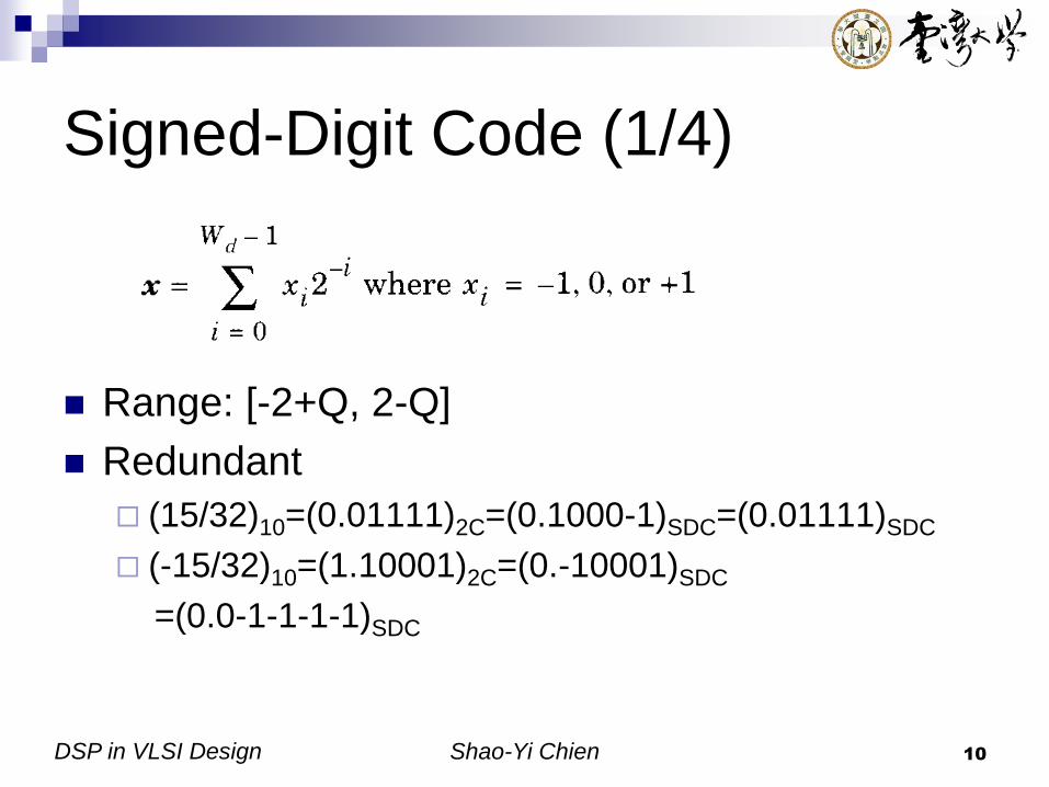
Signed-Digit Code (1/4)
Range: [-2+Q, 2-Q]
Redundant
(15/32)10=(0.01111)2C=(0.1000-1)SDC=(0.01111)SDC
(-15/32)10=(1.10001)2C=(0.-10001)SDC
=(0.0-1-1-1-1)SDC

DSP in VLSI Design Shao-Yi Chien 11
Signed-Digit Code (2/4)
SDC number is not unique
Has problems to
Quantize
Compare
Overflow check
Change to conventional number systems for
these operations
DSP in VLSI Design Shao-Yi Chien 12
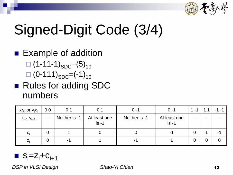
Signed-Digit Code (3/4)
Example of addition (1-11-1)SDC=(5)10
(0-111)SDC=(-1)10
Rules for adding SDC numbers
si=zi+ci+1
xiyi or yixi 0 0 0 1 0 1 0 -1 0 -1 1 -1 1 1 -1 -1
xi+1 yi+1 -- Neither is -1 At least one
is -1
Neither is -1 At least one
is -1
-- -- --
ci 0 1 0 0 -1 0 1 -1
zi 0 -1 1 -1 1 0 0 0
DSP in VLSI Design Shao-Yi Chien 13
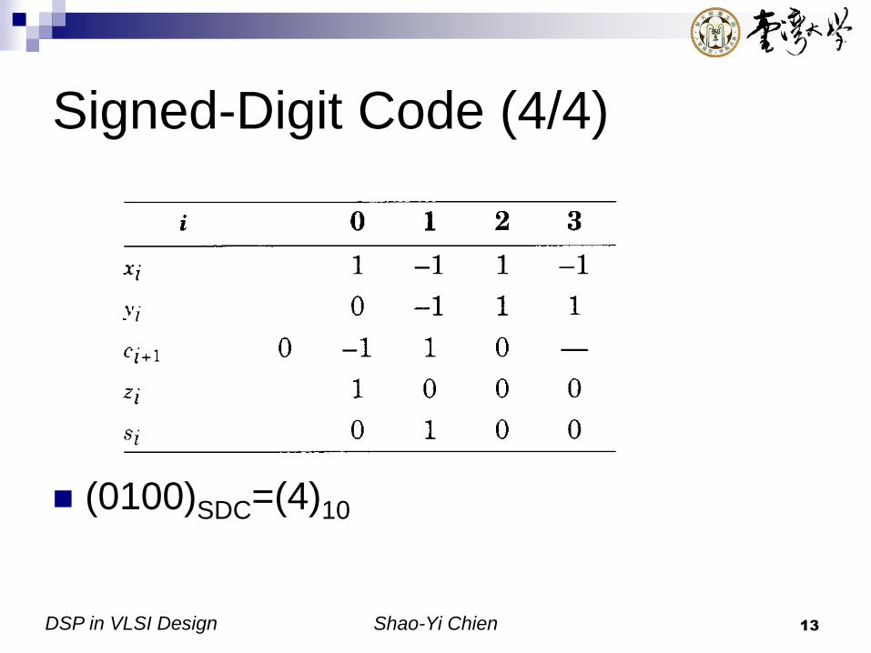
Signed-Digit Code (4/4)
(0100)SDC=(4)10
DSP in VLSI Design Shao-Yi Chien 14
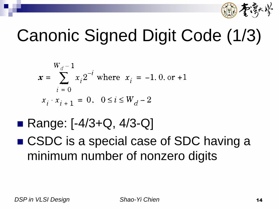
Canonic Signed Digit Code (1/3)
Range: [-4/3+Q, 4/3-Q]
CSDC is a special case of SDC having a
minimum number of nonzero digits

DSP in VLSI Design Shao-Yi Chien 15
Canonic Signed Digit Code (2/3)
Conversion of two’s-complement to CSDC numbers
(0.011111)2C=(0.10000-1)CSDC
Convert in iterative manner
Step1: 011…1100…-1
Step2: (-1,1)(0,-1), (0,1,1)(1,0,-1)
Ex: (0.110101101101)2C
=(1.00-10-100-10-101)CSDC

DSP in VLSI Design Shao-Yi Chien 16
Canonic Signed Digit Code (3/3)
Conversion of SDC to two’s complement
numbers
Separate the SDC number into two parts
One parts holds the digit that are either 0 or 1
The other part has –1 digits
Subtract these two numbers

DSP in VLSI Design Shao-Yi Chien 17
On-Line Arithmetic
The number systems with the property that it is possible to compute the i-th digit of the results using only the first (i+d)-th digit, where d is a small positive constant
Favorable in recursive algorithm using numbers with very long word lengths
SDC can be used for on-line addition and subtraction, d=1

DSP in VLSI Design Shao-Yi Chien 18
Residue Number Systems (1/2)
For a given number x and moduli set {mi}, i=1, 2, …, p x=qimi+ri RNS representation: x=(r1, r2, …, rp)
Advantages The arithmetic operations (+, -, *) can be performed
for each residue independently
Disadvantages Hard for comparison, overflow detection, and
quantization
Not easy to convert to other number systems

DSP in VLSI Design Shao-Yi Chien 19
Residue Number Systems (2/2)
Example
Moduli set={5,3,2}
Number range=5*3*2=30
9+19=(4,0,1)RNS+(4,1,1)RNS
=((4+4)5,(0+1)3, (1+1)2)RNS=(3,1,0)RNS=28
8*3=(3,2,0)RNS*(3,0,1)RNS
=((3*3)5,(2*0)3,(0*1)2)RNS=(4,0,0)RNS=24

DSP in VLSI Design Shao-Yi Chien 20
Bit-Parallel Arithmetic (1/2)
Addition and subtraction
Ripple carry adder (RCA) (carry propagation adder, CPA)
Carry-look-ahead adder (CLA)
Carry-save adder
Carry-select adder (CSA)
Carry-skip adder
Conditional-sum adder

DSP in VLSI Design Shao-Yi Chien 21
Bit-Parallel Arithmetic (2/2)
Multiplication
Shift-and-add multiplication
Booth’s algorithm
Tree-based multipliers
Array multipliers
Look-up table techniques

DSP in VLSI Design Shao-Yi Chien 22
Ripple Carry Adder (RCA) (1/2)
Also called carry propagation adder (CPA)
Full adder

DSP in VLSI Design Shao-Yi Chien 23
Ripple Carry Adder (RCA) (2/2)
The speed of the RCA is determined by
the carry propagation time
Ripple-carry adder Ripple-carry adder/subtractor

DSP in VLSI Design Shao-Yi Chien 24
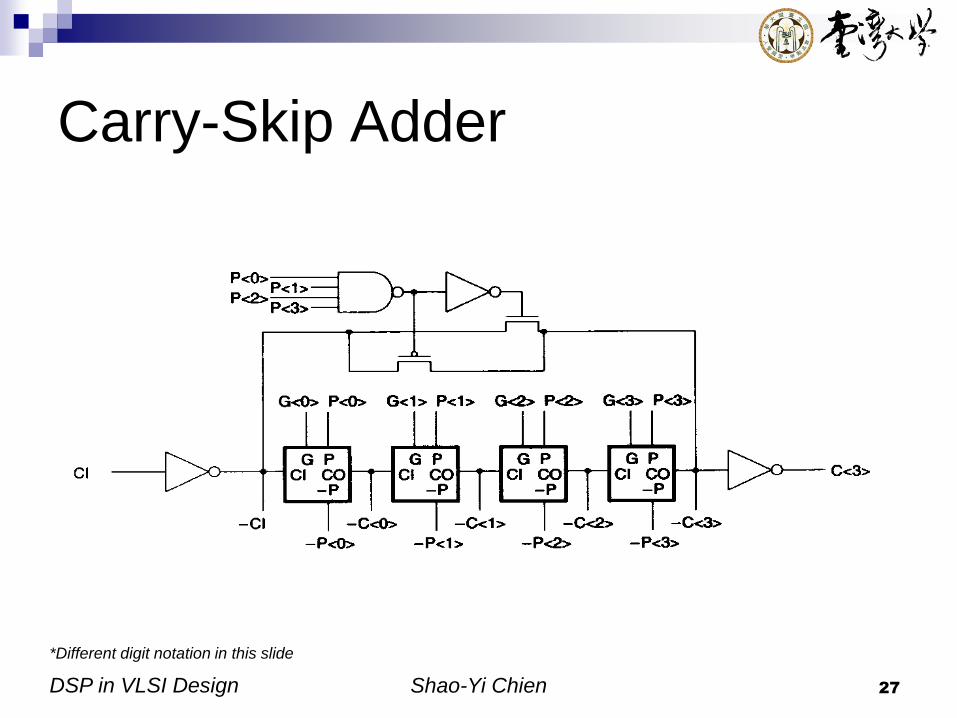
Carry-Look-Ahead Adder (CLA)
Generate the carry with separate circuits
Ci=Gi+Pi.Ci-1
Gi=Ai.Bi
Pi=Ai+Bi
*Different digit notation in this slide

DSP in VLSI Design Shao-Yi Chien 25
Carry-Save Adder
Used when adding three or more operands
Reduce the number of operands by one for each
stage
FA
x3 cin
3y
3
s3
c3
FA
x2
cin2 y
2
s2c
2
FA
x1
cin1 y
1
s1c
1
FA
x0
cin0 y
0
s0
c0
*Different digit notation in this slide

DSP in VLSI Design Shao-Yi Chien 26
Carry-Select Adder (CSA)
*Different digit notation in this slide
DSP in VLSI Design Shao-Yi Chien 27
Carry-Skip Adder
*Different digit notation in this slide
DSP in VLSI Design Shao-Yi Chien 28
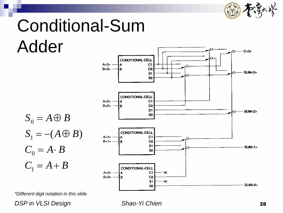
Conditional-Sum
Adder
*Different digit notation in this slide
BAC
BAC
BAS
BAS
1
0
1
0
)(

DSP in VLSI Design Shao-Yi Chien 29
Multiplication
Bit-parallel multiplication

DSP in VLSI Design Shao-Yi Chien 30
Shift-and-Add Multiplication (1/2)

DSP in VLSI Design Shao-Yi Chien 31
Shift-and-Add Multiplication (2/2)
The operation can
be reduced with
CSDC
Can be used to
design fix-operand
multiplier
DSP in VLSI Design Shao-Yi Chien 32
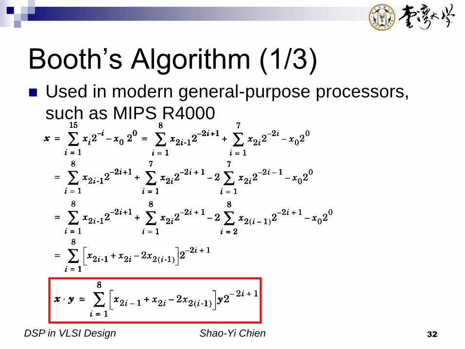
Booth’s Algorithm (1/3) Used in modern general-purpose processors,
such as MIPS R4000

DSP in VLSI Design Shao-Yi Chien 33
Booth’s Algorithm (2/3)
x2i-2 x2i-1 x2i x2i-1’ Operation Comments
0 0 0 0 +0 String of zeros
0 0 1 1 +y Beginning of 1s
0 1 0 1 +y A single 1
0 1 1 2 +2y Beginning of 1s
1 0 0 -2 -2y End of 1’s
1 0 1 -1 -y A single 0
(beginning/end of 1’s)
1 1 0 -1 -y End of 1’s
1 1 1 0 -0 String of 1’s
DSP in VLSI Design Shao-Yi Chien 34
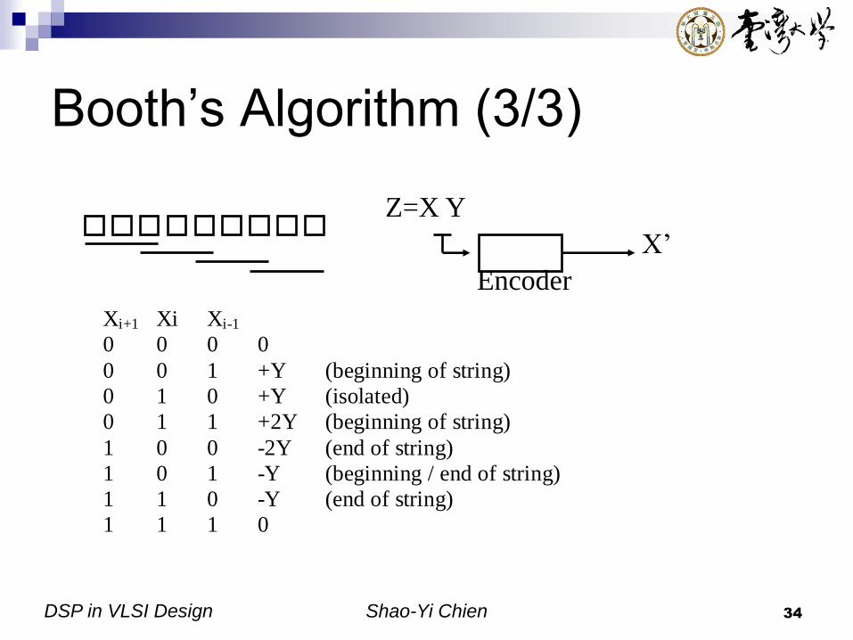
Booth’s Algorithm (3/3)
Z=X Y
Encoder
X’
Xi+1 Xi Xi-1
0 0 0 0
0 0 1 +Y (beginning of string)
0 1 0 +Y (isolated)
0 1 1 +2Y (beginning of string)
1 0 0 -2Y (end of string)
1 0 1 -Y (beginning / end of string)
1 1 0 -Y (end of string)
1 1 1 0

DSP in VLSI Design Shao-Yi Chien 35
Tree-Based Multipliers (Wallace
Tree Multipliers)

DSP in VLSI Design Shao-Yi Chien 36
Array Multipliers (1/3)
Baugh-
Wooley’s
multiplier

DSP in VLSI Design Shao-Yi Chien 37
Array Multipliers (2/3)
Partial products

DSP in VLSI Design Shao-Yi Chien 38
Array Multipliers (3/3)

DSP in VLSI Design Shao-Yi Chien 39
Look-Up Table Techniques
A multiplier AxB can be done with a large
table with 2WA+WB words
Simplified method
Can be implemented with one addition, two
subtraction, and two table look-up operations
4
)(
4
)( 22 yxyxyx

DSP in VLSI Design Shao-Yi Chien 40
Bit-Serial Arithmetic
Advantages
Significantly reduce chip area
Eliminate wide bus
Small processing elements
Higher clock frequency
Often superior than bit-parallel
Disadvantages
S/P P/S interface
Complicated clocking scheme
DSP in VLSI Design Shao-Yi Chien 41
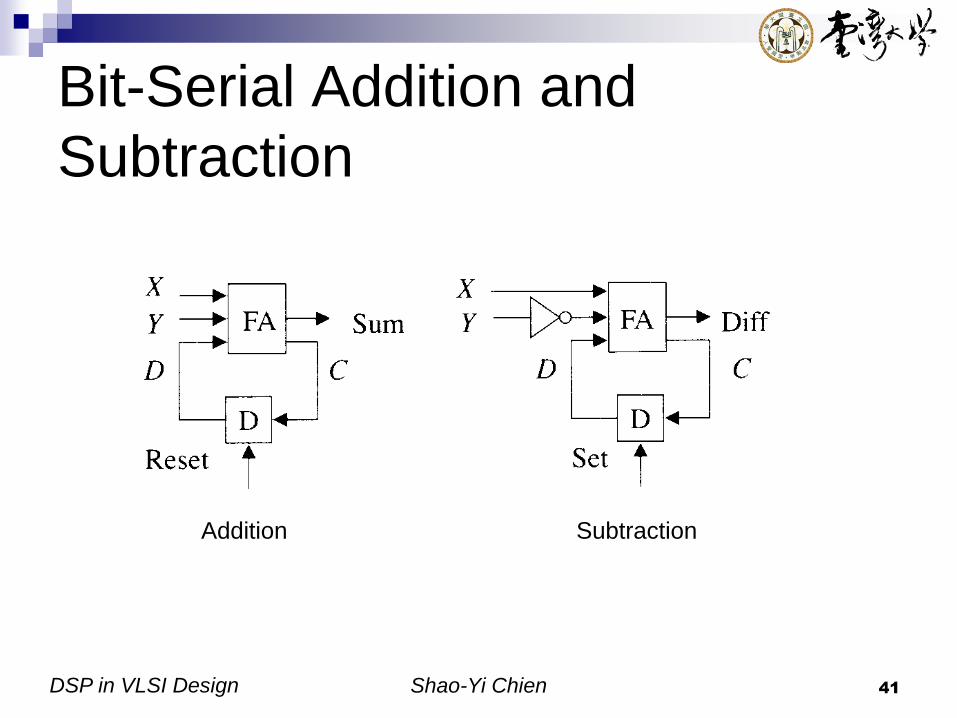
Bit-Serial Addition and
Subtraction
Addition Subtraction

DSP in VLSI Design Shao-Yi Chien 42
Serial/Parallel Multiplier
Use carry-save adders
Need Wd+Wc-1 cycles to compute the
result

DSP in VLSI Design Shao-Yi Chien 43
Modified Serial/Parallel
Multiplier
Can be
implemented
with a half adder

DSP in VLSI Design Shao-Yi Chien 44
Transpose Serial/Parallel
Multiplier
DSP in VLSI Design Shao-Yi Chien 45
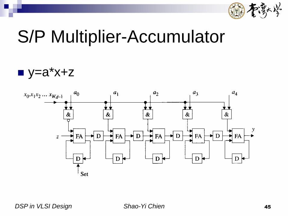
S/P Multiplier-Accumulator
y=a*x+z

DSP in VLSI Design Shao-Yi Chien 46
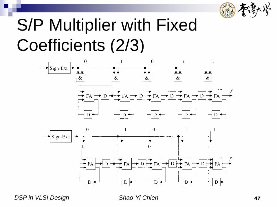
S/P Multiplier with Fixed
Coefficients (1/3)
Remove all AND gates
Remove all FAs and corresponding D flip-flops, starting with the MSB in the coefficient, up to the first 1 in the coefficient
Replace each FA that corresponds to a zero-bit in the coefficient with a feedthrough
DSP in VLSI Design Shao-Yi Chien 47
S/P Multiplier with Fixed
Coefficients (2/3)

DSP in VLSI Design Shao-Yi Chien 48
S/P Multiplier with Fixed
Coefficients (3/3)
The number of FA = (the number of 1’s)-1
The number of D flip-flops = the number of 1-bit positions between the first and last bit positions
DSP in VLSI Design Shao-Yi Chien 49
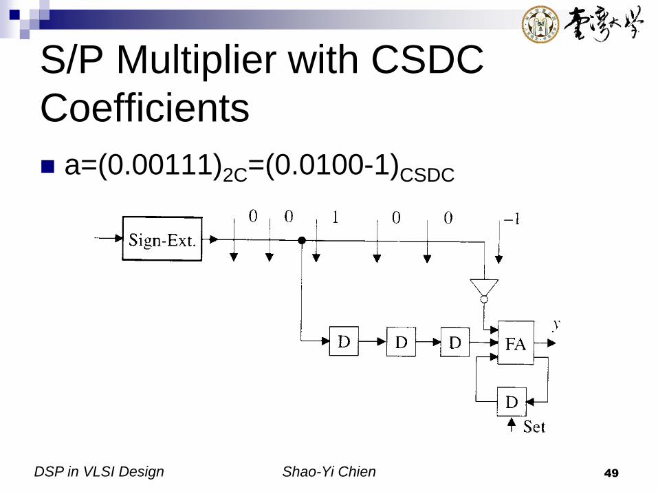
S/P Multiplier with CSDC
Coefficients
a=(0.00111)2C=(0.0100-1)CSDC

DSP in VLSI Design Shao-Yi Chien 50
Minimum Number of Basic
Operations

DSP in VLSI Design Shao-Yi Chien 51
Division
How to do binary division?
In the following slides, we define Dividend z = z2k-1z2k-2…z1z0
Divisor d = dk-1dk-2…d1d0
Quotient q = qk-1qk-2…q1q0
Remainder s = [z-(dxq)]=sk-1sk-2…s1s0
Major reference:
B. Parham, Computer Arithmetic: Algorithms and Hardware Designs,
Oxford, 2000.
DSP in VLSI Design Shao-Yi Chien 52
What’s Different?
Added complication of requiring quotient digit selection or estimation
The terms to be subtracted from the dividend z are not known a priori but become known as the quotient digits are computed
The terms to be subtracted from the initial partial remainder must be produced from top to bottom
More difficult and slower than multiplication
Long critical path

DSP in VLSI Design Shao-Yi Chien 53
Division
Bit-serial division (sequential division algorithm)
Programmed division
Restoring bit-serial hardware divider
Nonrestoring bit-serial hardware divider
Division by constants
Array divider

DSP in VLSI Design Shao-Yi Chien 54
s(j)=2s(j-1)-qk-j(2kd) with s(0)=z and s(k)=2ks
Or For j=1 to k
{
If(2s(j-1)>=(2kd))
{
qk-j=1;
s(j)=2s(j-1)-(2kd);
}
Else
{
qk-j=0;
s(j)=2s(j-1);
}
}
Subtract
Bit-Serial division
(Sequential Division) Algorithm
Shift

DSP in VLSI Design Shao-Yi Chien 55
Programmed Division
Need more than 200 instructions
for a 32-bit division!!

DSP in VLSI Design Shao-Yi Chien 56
Restoring Bit-Serial Hardware
Divider (1/3)
“Restoring division”
Assume q=1 first, do the trial difference
The remainder is restored to its correct value
if the trial subtraction indicates that 1 was not
the right choice for q

DSP in VLSI Design Shao-Yi Chien 57
Restoring Bit-Serial Hardware
Divider (2/3)

DSP in VLSI Design Shao-Yi Chien 58
Restoring Bit-Serial Hardware
Divider (3/3) Can be shared together
Critical path
DSP in VLSI Design Shao-Yi Chien 59
Nonrestoring Bit-Serial
Hardware Divider (1/4)
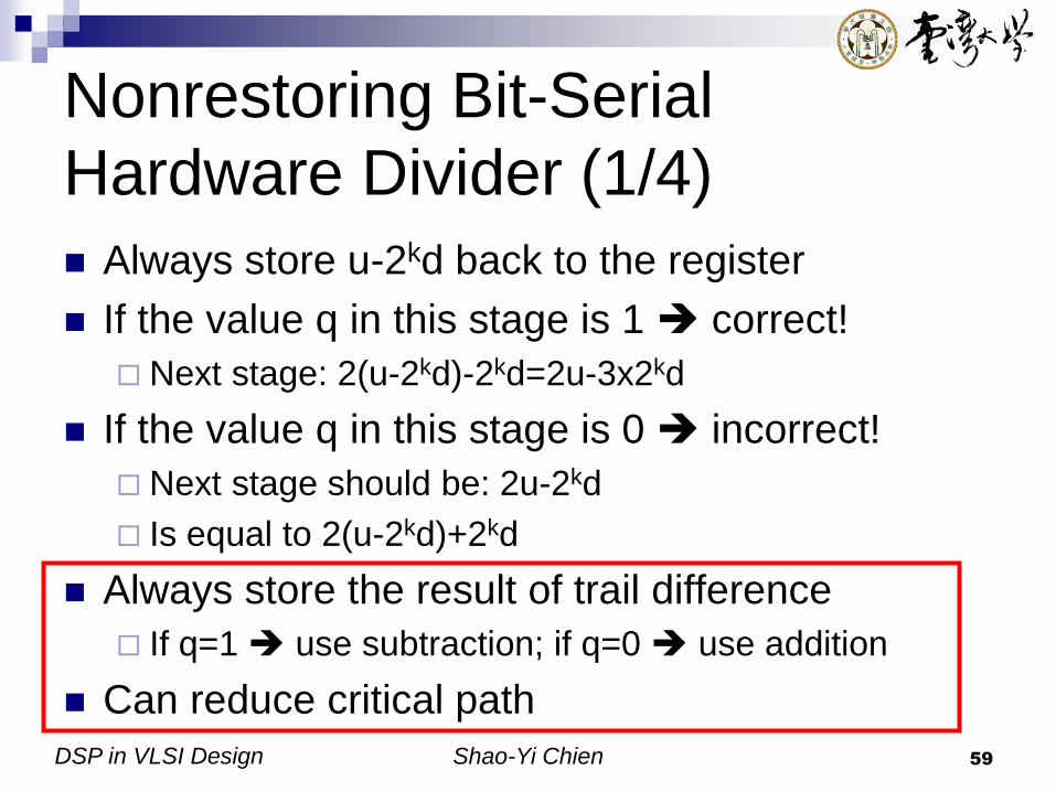
Always store u-2kd back to the register
If the value q in this stage is 1 correct!
Next stage: 2(u-2kd)-2kd=2u-3x2kd
If the value q in this stage is 0 incorrect!
Next stage should be: 2u-2kd
Is equal to 2(u-2kd)+2kd
Always store the result of trail difference
If q=1 use subtraction; if q=0 use addition
Can reduce critical path

DSP in VLSI Design Shao-Yi Chien 60
Nonrestoring Bit-Serial
Hardware Divider (2/4)

DSP in VLSI Design Shao-Yi Chien 61
Nonrestoring Bit-Serial
Hardware Divider (3/4)
Critical path

DSP in VLSI Design Shao-Yi Chien 62
Nonrestoring Bit-
Serial Hardware
Divider (4/4)

DSP in VLSI Design Shao-Yi Chien 63
Division by Constants (1/2)
Use lookup table + constant multiplier
Exploit the following equations
Consider odd divisor only since even divisor
can be performed by first dividing by an odd
integer and then shifting the result
For an odd integer d, there exists an odd
integer m such that d x m=2n-1
DSP in VLSI Design Shao-Yi Chien 64
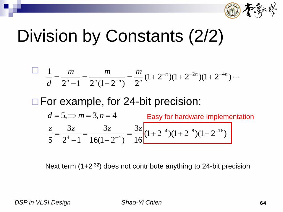
Division by Constants (2/2)
For example, for 24-bit precision:
)21)(21)(21(2)21(212
1 42 nnn
nnnn
mmm
d
)21)(21)(21(16
3
)21(16
3
12
3
5
4,3,5
1684
44
zzzz
nmd
Next term (1+2-32) does not contribute anything to 24-bit precision
Easy for hardware implementation

DSP in VLSI Design Shao-Yi Chien 65
Array Divider (1/2)
Restoring array divider
FS: full subtractor
The critical path
passes through all k2
cells

DSP in VLSI Design Shao-Yi Chien 66
Array Divider (2/2)
Nonrestoring array divider
FA: full adder
The critical path
passes through all k2
cells

DSP in VLSI Design Shao-Yi Chien 67
Distributed Arithmetic (1/7)
Most DSP algorithms involve sum-of-
products (inner products)
Distributed arithmetic (DA) is an efficient
procedure for computing inner products
between a fixed and a variable data vector
Fixed coefficient
DSP in VLSI Design Shao-Yi Chien 68
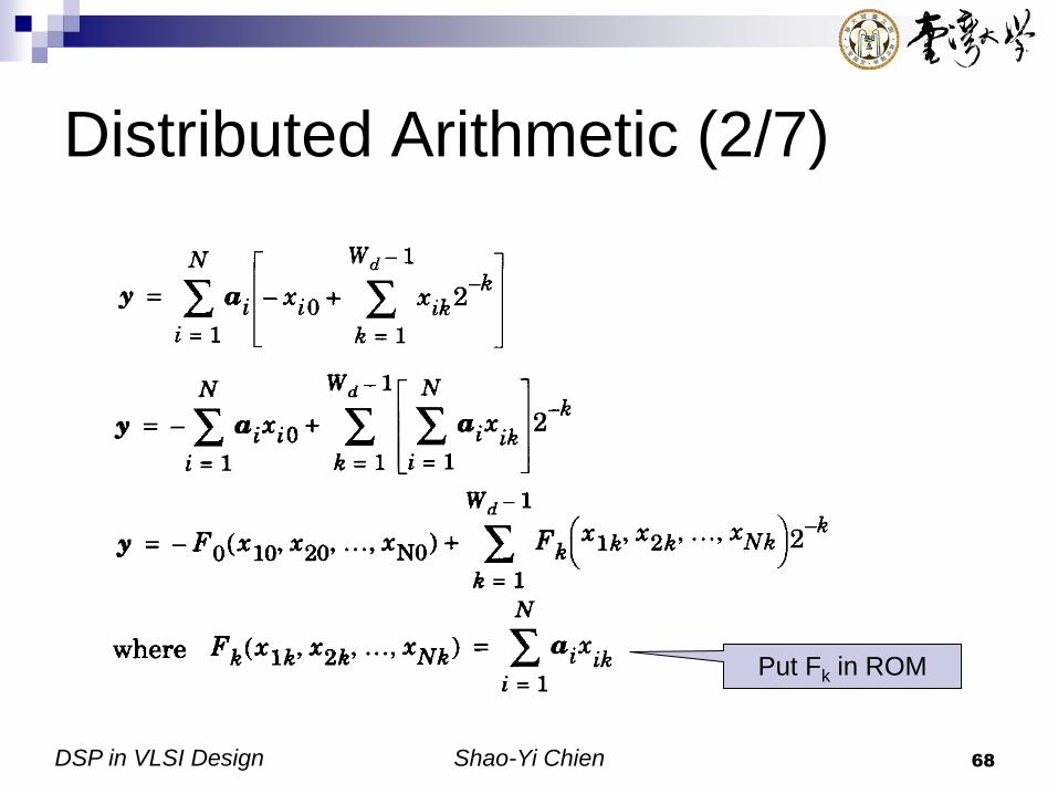
Distributed Arithmetic (2/7)
Put Fk in ROM

DSP in VLSI Design Shao-Yi Chien 69
Distributed Arithmetic (3/7)
DA can be
implemented with a
ROM and a shift-
accumulator
The computation
time: Wd cycles
Word length of
ROM: )(log2 NWW CROM Data input from
LSB to MSB in
bit-serial

DSP in VLSI Design Shao-Yi Chien 70
Distributed Arithmetic (4/7)
Example
y=a1x1+a2x2+a3x3
a1=(0.0100001)2C
a2=(0.1010101)2C
a3=(1.1110101)2C
(a) The table? (b) The word length of the
shift-accumulator?

DSP in VLSI Design Shao-Yi Chien 71
Distributed Arithmetic (5/7)
Ans:
(a)
(b) Word length=7 bits + 1 bit (sign bit) +1 bit (guard bit) = 9 bits
DSP in VLSI Design Shao-Yi Chien 72
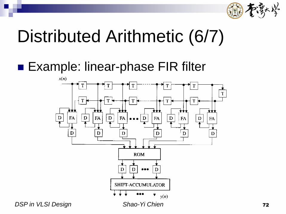
Distributed Arithmetic (6/7)
Example: linear-phase FIR filter
DSP in VLSI Design Shao-Yi Chien 73
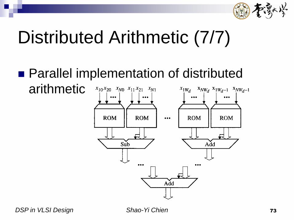
Distributed Arithmetic (7/7)
Parallel implementation of distributed
arithmetic
DSP in VLSI Design Shao-Yi Chien 74
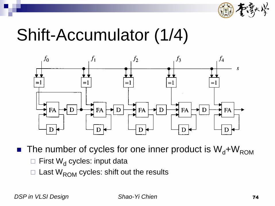
Shift-Accumulator (1/4)
The number of cycles for one inner product is Wd+WROM
First Wd cycles: input data
Last WROM cycles: shift out the results

DSP in VLSI Design Shao-Yi Chien 75
Shift-Accumulator (2/4)
Shift-accumulator augmented with two
shift registers

DSP in VLSI Design Shao-Yi Chien 76
Shift-Accumulator (3/4)
Scheduling
Clock cycle NCL=max{WROM, Wd}
LSP(0)
MSP(0)
LSP(1)
MSP(1)
LSP(2)
MSP(2)......
Wd
WROM
DSP in VLSI Design Shao-Yi Chien 77
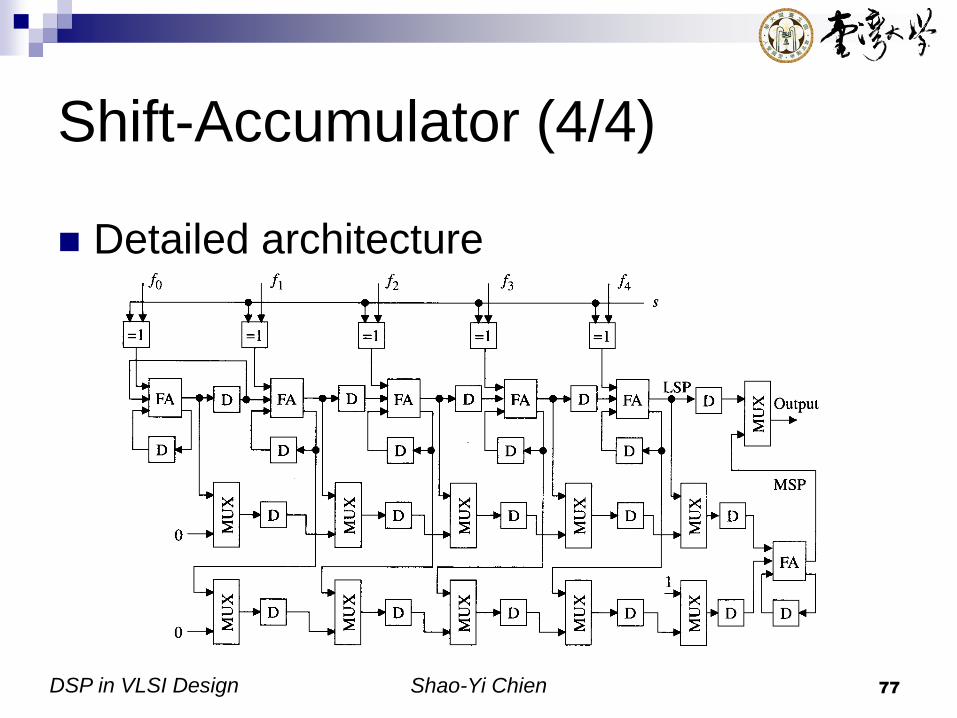
Shift-Accumulator (4/4)
Detailed architecture

DSP in VLSI Design Shao-Yi Chien 78
Reducing the Memory Size (1/4)
Method 1:
memory
partition
2*2N/2 < 2N
Ex: 2*25 = 64
< 210 = 1024
DSP in VLSI Design Shao-Yi Chien 79
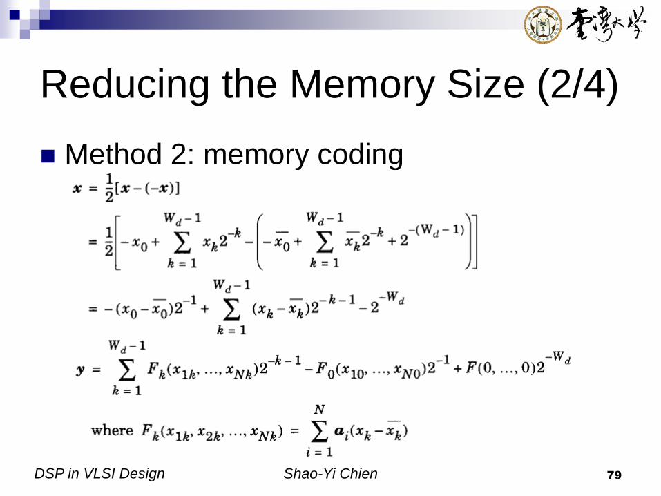
Reducing the Memory Size (2/4)
Method 2: memory coding

DSP in VLSI Design Shao-Yi Chien 80
Reducing the Memory Size (3/4)
Complement

DSP in VLSI Design Shao-Yi Chien 81
Reducing the Memory Size (4/4)

DSP in VLSI Design Shao-Yi Chien 82
CORDIC
CORDIC (COordinate Rotation DIgital Computer)
An iterative arithmetic algorithm introduced by
Volder in 1956
Can handle many elementary functions, such as
trigonometric, exponential, and logarithm with only
shift-and-add arithmetic
For these functions CORDIC based architecture is
much efficient than multiplier and accumulator (MAC)
based architecture
Suitable for transformations and matrix based filters
Major reference:
[1] A.-Y. Wu, “CORDIC,” Slides of Advanced VLSI
[2] Y. H. Hu, “CORDIC-based VLSI architectures for digital signal
processing,” IEEE Signal Processing Magazine, pp. 16—35, July 1992.
[3] J. E. Volder, “The Birth of CORDIC,” J. VLSI Signal Processing,
vol.25, pp. 101—105, 2000.

DSP in VLSI Design Shao-Yi Chien 83
The Birth of CORDIC
B-58 Supersonic Bomber
CORDIC I
CORDIC II

DSP in VLSI Design Shao-Yi Chien 84
Simple Concepts of CORDIC
(1/2)
Originally, CORDIC is invented to deal
with rotation problem with shift-and-add
arithmetic
y
x
y
x
cossin
sincos
'
'
(x, y)
(x', y')

DSP in VLSI Design Shao-Yi Chien 85
Simple Concepts of CORDIC
(2/2)
How to make it with shift-and-add?
Decompose the desired rotation angle into
small rotation angles (micro-rotation)
Rotate finite times (by “elementary angles”
) to achieve the desired
rotation 1
2 3
4
}10|{ niai

DSP in VLSI Design Shao-Yi Chien 86
Conventional CORDIC
Algorithm (1/2)
ii
i
i
i
i
i
i
i
i
ii
ii
aa
iy
ixa
iy
ix
iy
ix
a
aa
iy
ix
iy
ix
aa
aa
iy
ix
2
1
21
1cos,2tan
)(
)(
12
21cos
)1(
)1(
)(
)(
1tan
tan1cos
)1(
)1(
)(
)(
cossin
sincos
)1(
)1(

DSP in VLSI Design Shao-Yi Chien 87
Conventional CORDIC
Algorithm (2/2)
}1,1{ :rotation of Mode
21
1 :factor Scaling
12
21
12
21
12
21
cossin
sincos
'
'
1
0
22
)1(
1
)1(
1
0
0
0
0
i
n
i
i
i
n
n
n
n
i
i
i
i
S
y
x
S
y
x
y
x
Can be implemented
with shift-and-add
arithmetic
(x, y)
(x', y')
22
21
2
11
11
1
00
01
0
2tan1
2tan1
2tan1
a
a
a
0
12
Scaling

DSP in VLSI Design Shao-Yi Chien 88
Generalized CORDIC (1/2)
Target:
i-th elementary rotation angle is defined by
1
0
)(n
i
mi ia
12tanh
12tan
02
2tan1
)(),1(1
).1(1
),0(
),(1
m
m
m
mm
iais
is
is
ims
m
Linear coordinate
Circular coordinate
Hyperbolic coordinate
sequenceshift integer gdescreasin-non :),(
rotation of mode :}1,1{
x is yx vector a of norm 22
ims
my
i
T

DSP in VLSI Design Shao-Yi Chien 89
Generalized CORDIC (2/2)
x2+y2=1
v(0)
v(1)
v(2)
v(3)
v(4)
v(i)=[x(i) y(i)]T
Circular Rotation
(m=1)
x=1
v(0)
v(1)
v(2)
v(3)
v(i)=[x(0) y(i)]T
Linear Rotation
(m->0)
y=-x
v(0)
v(1)
v(2)
v(3)
v(i)=[x(i) y(i)]T
Hyperbolic Rotation
(m=-1)y=x
x2-y2=1

DSP in VLSI Design Shao-Yi Chien 90
CORDIC Algorithm
)(
)(
21
1
)(
)(
)(
1
/* only) 1for (requiredoperation Scaling */
loop-i End
)()()1(
/*equation updating Angle */
)(
)(
12
21
)1(
)1(
/*equationiteration CORDIC */
Do 1,-n to0iFor
)0(),0(),0(Given :Initiation
1
0
),(22
),(
),(
ny
nx
mny
nx
nKy
x
m
iaiziz
iy
ix
iy
ix
zyx
n
i
ims
imf
f
mi
ims
i
ims
i
Scaling
),( ims
i
Remained problems:
DSP in VLSI Design Shao-Yi Chien 91
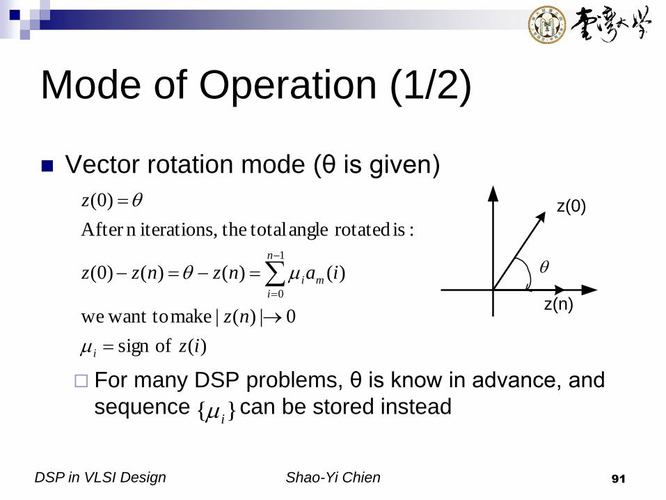
Mode of Operation (1/2)
Vector rotation mode (θ is given)
For many DSP problems, θ is know in advance, and
sequence can be stored instead
)( ofsign
0|)(| make want towe
)()()()0(
:is rotated angle total the,iterationsn After
)0(
1
0
iz
nz
ianznzz
z
i
n
i
mi
}{ i
z(n)
z(0)

DSP in VLSI Design Shao-Yi Chien 92
Mode of Operation (2/2)
Angle accumulation mode (θ is not given)
The objective is to rotate the given initial
vector [x(0) y(0)]T back to the x-axis
Summary
)()( ofsign
0)0(set
iyix
z
i
)()( ofsign
)( ofsign
iyix
izi
Vector rotation mode
Angle accumulation mode

DSP in VLSI Design Shao-Yi Chien 93
Shift Sequence
Usually defined in advance
Walther has proposed a set of shift
sequence for each of the three coordinate
systems
For m=0 or 1, s(m,i)=i
For m=-1, s(-1, i)=1, 2, 3, 4, 4, 5, …, 12, 13,
13, 14, …

DSP in VLSI Design Shao-Yi Chien 94
Scaling Operation
Significant computation overhead of CORDIC
Fortunately, since , and assume is given, can be computed in advance
Two approaches to compute scaling
CSD representation
Project of factors
)(
1
nKm
1|| i
)(nKm
)},({ ims
P
p
i
p
m
p
nK 1
2)(
1
Q
q
q
i
q
m
q
nK 1
)21()(
1
1q
DSP in VLSI Design Shao-Yi Chien 95
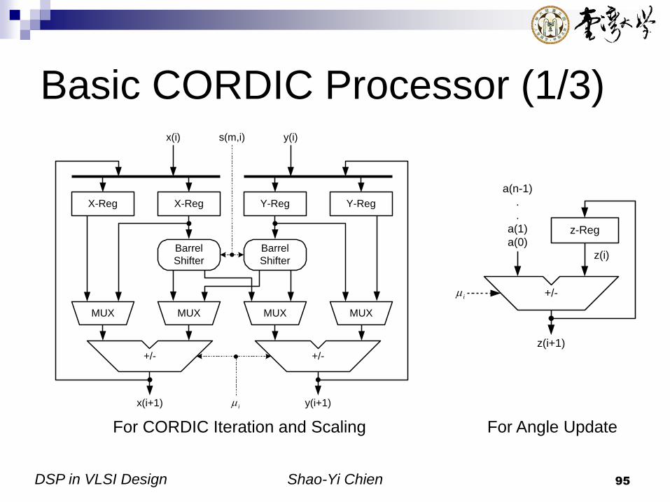
Basic CORDIC Processor (1/3)
z-Reg
+/-
z(i)
z(i+1)
i
a(n-1)
.
.
a(1)
a(0)
For CORDIC Iteration and Scaling For Angle Update
X-Reg
Barrel
Shifter
X-Reg Y-Reg
Barrel
Shifter
Y-Reg
MUXMUX MUX MUX
+/- +/-
x(i) y(i)
x(i+1) y(i+1)
s(m,i)
i
DSP in VLSI Design Shao-Yi Chien 96
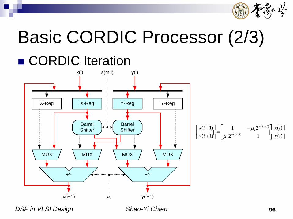
Basic CORDIC Processor (2/3)
CORDIC Iteration
)(
)(
12
21
)1(
)1(),(
),(
iy
ix
iy
ixims
i
ims
i
X-Reg
Barrel
Shifter
X-Reg Y-Reg
Barrel
Shifter
Y-Reg
MUXMUX MUX MUX
+/- +/-
x(i) y(i)
x(i+1) y(i+1)
s(m,i)
i

DSP in VLSI Design Shao-Yi Chien 97
Basic CORDIC Processor (3/3)
Scaling
X-Reg
Barrel
Shifter
X-Reg Y-Reg
Barrel
Shifter
Y-Reg
MUXMUX MUX MUX
+/- +/-
x(i) y(i)
x(i+1) y(i+1)
ip
or iq
qp or
P
p
i
p
m
p
nK 1
2)(
1
Q
q
i
q
m
q
nK 1
)21()(
1
I:
II:
)('2)(')1('
)('2)(')1('
:II Type
)(2)(')1('
)(2)(')1('
:I Type
)()0('),()0('Given
qxqyqy
qxqxqx
nxpypy
nxpxpx
nyynxx
q
q
p
p
i
q
i
q
i
p
i
p

DSP in VLSI Design Shao-Yi Chien 98
Parallel and Pipelined Arrays
n stages for CORDIC, and s stages for scaling
Parallel
Pipelined
CORDIC
Processor
(1)
x(0)
y(0)
CORDIC
Processor
(2)
CORDIC
Processor
(n+s)
...
...
xf
yf
CORDIC
Processor
(1)
x(0)
y(0)
CORDIC
Processor
(2)
CORDIC
Processor
(n+s)
...
...
xf
yf
D D D

DSP in VLSI Design Shao-Yi Chien 99
Discrete Fourier Transform
(DFT) with CORDIC (1/2) DFT
DFT with CORDIC
N
Nkj
N
kj
N
kj
eNXeXeXKY)1(21202
)1()1()0()(
loop-k End
)(
),()(
/*operation Scaling */
loop-m End
),(
),(
)(
)(
2cos
2sin
2sin
2cos
)(),1(
),1(
Do 1,-N to0mFor
Do 1,-N to0kFor
10for 0),0( :Initiation
1
1
nK
kNYkY
kmY
kmY
mx
mx
N
mk
N
mkN
mk
N
mk
nKkmY
kmY
NkkY
i
r
i
r
i
r

DSP in VLSI Design Shao-Yi Chien 100
Discrete Fourier Transform
(DFT) with CORDIC (2/2)
0
m=0->N-1
Vector
Rotation
xr(m)
xi(m)
...
...
Buffer
m=0->N-1
Vector
Rotation
Nkm /2
Y(0) Y(k)
...
...
Buffer
m=0->N-1
Vector
Rotation
NmN /)1(2
Y(N-1)
xr(m)
xi(m)