product description - banggoodimg.banggood.com/file/products/20170828230102single...iv. basic...
TRANSCRIPT
组装手册PRODUCT DESCRIPTION
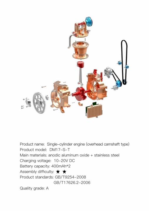
Product name: Single-cylinder engine (overhead camshaft type)Product model: DM17-S-T Main materials: anodic aluminum oxide + stainless steel Charging voltage: 10-20V DCBattery capacity: 400mAh*2Assembly difficulty:Product standards: GB/T9254-2008 GB/T17626.2-2006Quality grade: A

Assembly instructions for Teching Craftsman
“Teching Craftsman” is a metallic assembly model other than a toy for playing only. It serves to improve hands-on skills of children and youngsters, and let them learn common industrial knowledge mainly. By keeping using our products, the user can reach the goal of assembly – refitting – creation in stages.
The requirements for product assembly are as follows:
◆ Perform assembly rigorously and orderly, keep the tabletop tidy, look at drawings carefully, and pay attention to safety;
◆ If you have any doubt when adjusting any assembly clearance or tightness after the completion of assembly, please refer to our website or WeChat public account;
◆ The user is encouraged to modify part defects or fitting clearances, and apply lubricant under adult supervision to further improve assembly;
◆ The user is encouraged to use simple material removal tools (file, sandpaper, etc.) under adult supervision;
◆ The user is encouraged to modify or generally refit parts of this product to enter the refitting stage as early as possible;
◆ The user may disassemble this product and put it in the package again according to the parts list attached hereto;
◆ If any part is lost, please inquire of or purchase it from us (Teching store on www.taobao.com);
If you are willing to share with us, after completing product assembly tasks of different difficulty levels at different stages, you will receive corresponding gifts, and have a chance to win our special medals and take part in relevant events.
Safety Tips
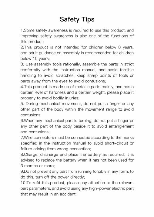
1.Some safety awareness is required to use this product, and improving safety awareness is also one of the functions of this product; 2.This product is not intended for children below 8 years, and adult guidance on assembly is recommended for children below 10 years; 3. Use assembly tools rationally, assemble the parts in strict conformity with the instruction manual, and avoid forcible handling to avoid scratches; keep sharp points of tools or parts away from the eyes to avoid contusions;4.This product is made up of metallic parts mainly, and has a certain level of hardness and a certain weight; please place it properly to avoid bodily injuries; 5. During mechanical movement, do not put a finger or any other part of the body within the movement range to avoid contusions; 6.When any mechanical part is turning, do not put a finger or any other part of the body beside it to avoid entanglement and contusions; 7.Wire connectors must be connected according to the marks specified in the instruction manual to avoid short-circuit or failure arising from wrong connection; 8.Charge, discharge and place the battery as required; it is advised to replace the battery when it has not been used for 3 months or more; 9.Do not prevent any part from running forcibly in any form; to do this, turn off the power directly; 10.To refit this product, please pay attention to the relevant part parameters, and avoid using any high-power electric part that may result in an accident.
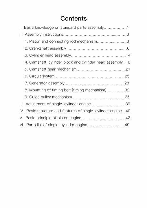
ContentsI. Basic knowledge on standard parts assembly………………1
II. Assembly instructions…………………………………..………3
1. Piston and connecting rod mechanism…………..…….…3
2. Crankshaft assembly ……………………………………..…6
3. Cylinder head assembly…………………………………….14
4. Camshaft, cylinder block and cylinder head assembly...18
5. Camshaft gear mechanism…………………………….…..21
6. Circuit system……………………………………………….25
7. Generator assembly ……………………………………….28
8. Mounting of timing belt (timing mechanism)…………...32
9. Guide pulley mechanism………………………………...…35
III. Adjustment of single-cylinder engine…………………....…39
IV. Basic structure and features of single-cylinder engine…40
V. Basic principle of piston engine…………………………..…42
VI. Parts list of single-cylinder engine………………………...49
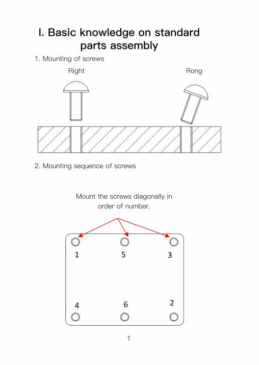
I. Basic knowledge on standard parts assembly
1. Mounting of screws
1
Right Rong
2. Mounting sequence of screws
Mount the screws diagonally in order of number.
1 5 3
4 26
2
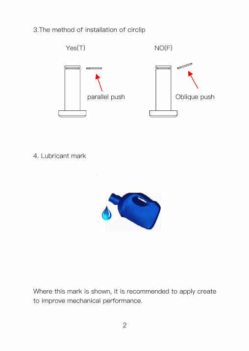
parallel push Oblique push
3.The method of installation of circlip Yes(T) NO(F)
4. Lubricant mark
Where this mark is shown, it is recommended to apply create to improve mechanical performance.
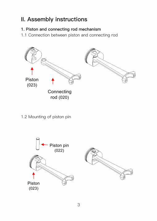
Connecting rod (020)
Piston (023)
II. Assembly instructions
1. Piston and connecting rod mechanism1.1 Connection between piston and connecting rod
1.2 Mounting of piston pin
Piston pin (022)
Piston (023)
3
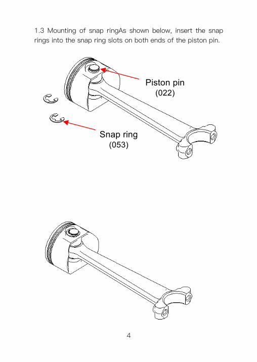
1.3 Mounting of snap ringAs shown below, insert the snap rings into the snap ring slots on both ends of the piston pin.
Piston pin (022)
Snap ring (053)
4
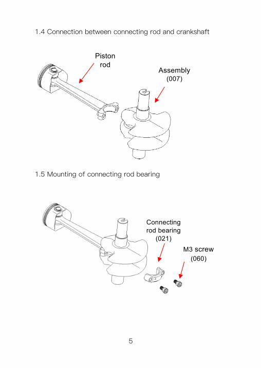
1.4 Connection between connecting rod and crankshaft
M3 screw(060)
Connecting rod bearing
(021)
Piston rod
Assembly (007)
1.5 Mounting of connecting rod bearing
5
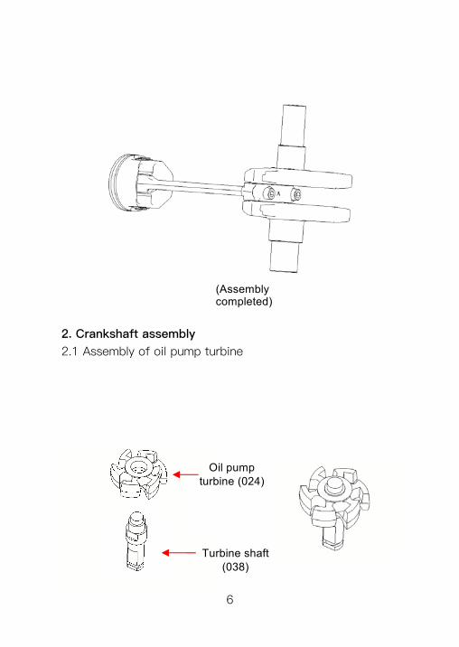
(Assembly completed)
Oil pump turbine (024)
Turbine shaft (038)
2. Crankshaft assembly2.1 Assembly of oil pump turbine
6
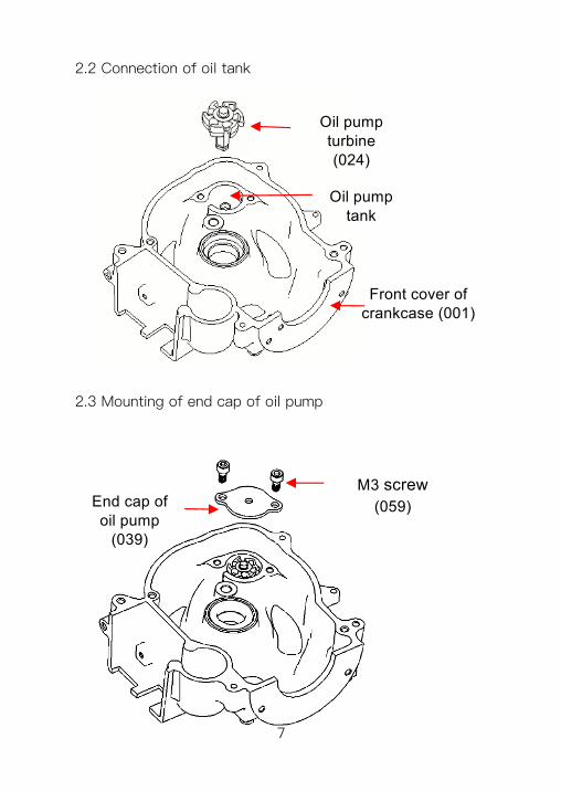
End cap of oil pump
(039)
M3 screw(059)
Oil pump tank
Oil pump turbine (024)
Front cover of crankcase (001)
2.2 Connection of oil tank
2.3 Mounting of end cap of oil pump
7
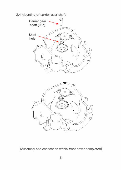
2.4 Mounting of carrier gear shaft
Shaft hole
Carrier gear shaft (037)
(Assembly and connection within front cover completed)
8
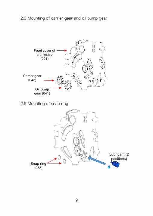
2.5 Mounting of carrier gear and oil pump gear
Front cover of crankcase
(001)
Carrier gear (042)
Oil pump gear (041)
Snap ring (053)
Lubricant (2 positions)
2.6 Mounting of snap ring
9
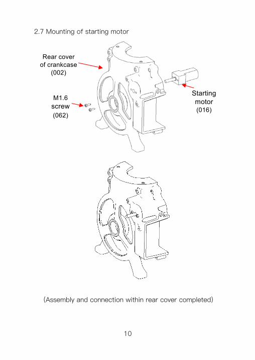
Rear cover of crankcase
(002)
Starting motor (016)
M1.6 screw(062)
2.7 Mounting of starting motor
(Assembly and connection within rear cover completed)
10
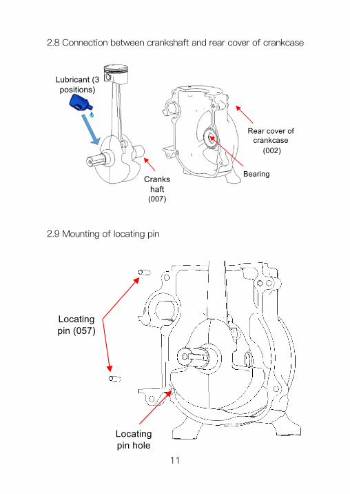
2.8 Connection between crankshaft and rear cover of crankcase
Rear cover of crankcase
(002)
Crankshaft (007)
Bearing
Lubricant (3 positions)
Locating pin (057)
Locating pin hole
2.9 Mounting of locating pin
11
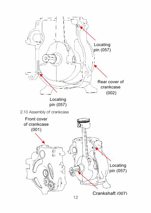
Locating pin (057)
Locating pin (057)
Rear cover of crankcase
(002)
Crankshaft (007)
Front cover of crankcase
(001)
Locating pin (057)
2.10 Assembly of crankcase
12
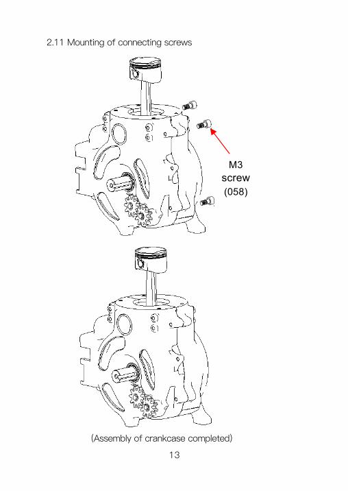
M3 screw(058)
2.11 Mounting of connecting screws
(Assembly of crankcase completed)
13
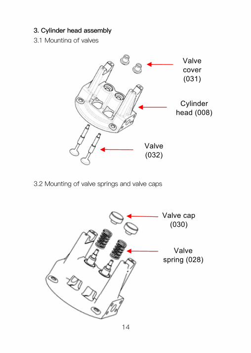
3. Cylinder head assembly3.1 Mounting of valves
Cylinder head (008)
Valve (032)
Valve cover (031)
Valve spring (028)
Valve cap (030)
3.2 Mounting of valve springs and valve caps
14
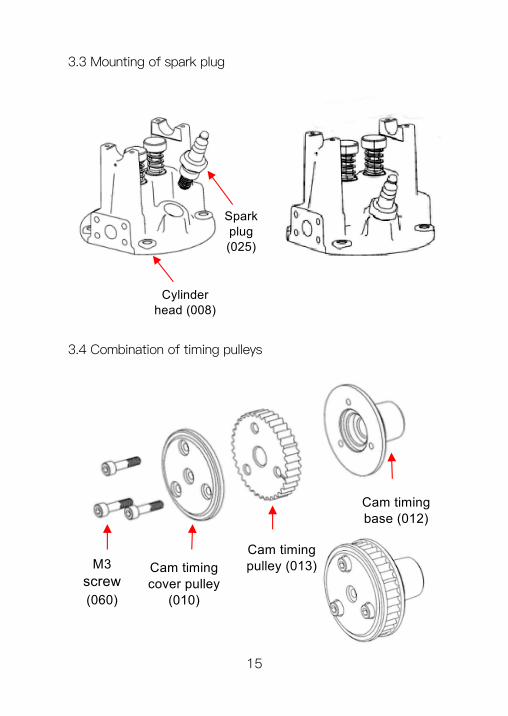
Spark plug (025)
Cylinder head (008)
3.3 Mounting of spark plug
3.4 Combination of timing pulleys
Cam timing base (012)
Cam timing pulley (013)Cam timing
cover pulley (010)
M3 screw(060)
15
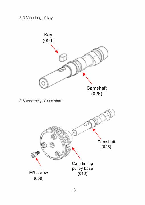
Key (056)
Camshaft (026)
Camshaft (026)
Cam timing pulley base
(012)M3 screw(059)
3.5 Mounting of key
3.6 Assembly of camshaft
16
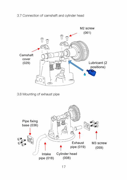
3.7 Connection of camshaft and cylinder head
M2 screw(061)
Camshaft cover (029) Lubricant (2
positions)
Pipe fixing base (036)
M3 screw(059)
Exhaust pipe (019)
Cylinder head (008)
Intake pipe (018)
3.8 Mounting of exhaust pipe
17
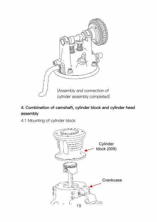
Crankcase
Cylinder block (009)
4. Combination of camshaft, cylinder block and cylinder head assembly
(Assembly and connection of cylinder assembly completed)
4.1 Mounting of cylinder block
18
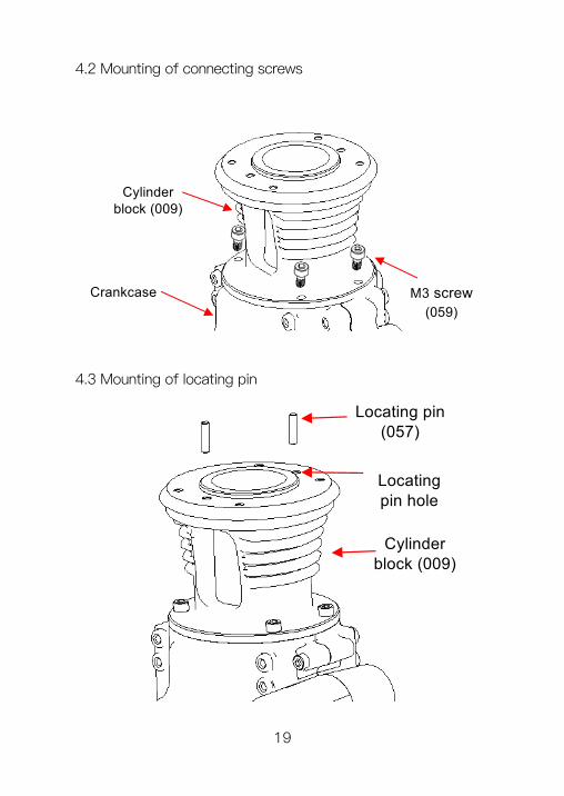
Cylinder block (009)
Crankcase M3 screw(059)
4.2 Mounting of connecting screws
Locating pin hole
Cylinder block (009)
Locating pin (057)
4.3 Mounting of locating pin
19
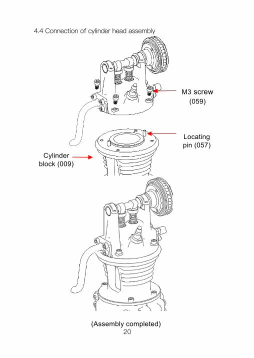
M3 screw(059)
Cylinder block (009)
Locating pin (057)
(Assembly completed)
4.4 Connection of cylinder head assembly
20
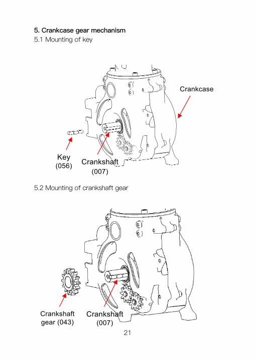
Crankshaft gear (043)
Crankshaft(007)
Key (056)
Crankshaft (007)
Crankcase
5. Crankcase gear mechanism5.1 Mounting of key
5.2 Mounting of crankshaft gear
21
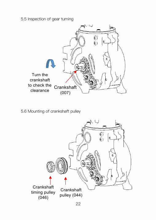
Crankshaft timing pulley
(046)
Crankshaft pulley (044)
Crankshaft (007)
Turn the crankshaft
to check the clearance
5.5 Inspection of gear turning
5.6 Mounting of crankshaft pulley
22
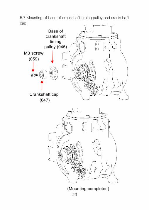
5.7 Mounting of base of crankshaft timing pulley and crankshaft cap
(Mounting completed)
Base of crankshaft
timing pulley (045)
M3 screw(059)
Crankshaft cap (047)
23
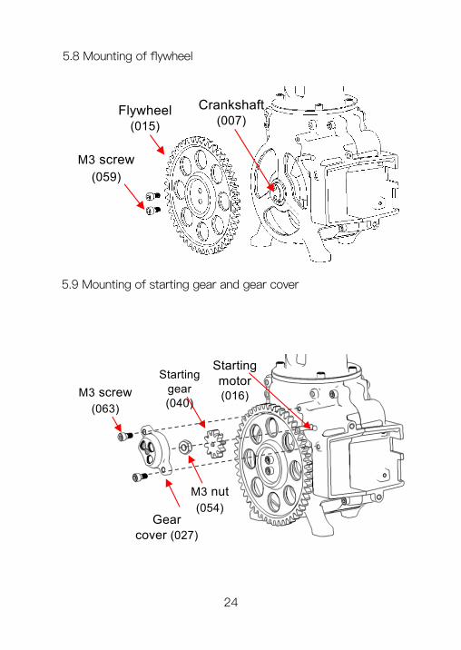
M3 screw(059)
Crankshaft (007)
Flywheel (015)
5.8 Mounting of flywheel
5.9 Mounting of starting gear and gear cover
Gear cover (027)
Starting gear (040)
Starting motor (016)M3 screw
(063)
M3 nut(054)
24
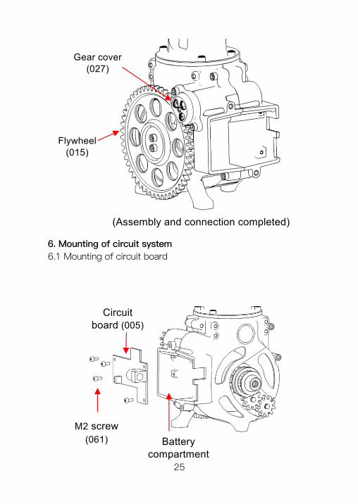
(Assembly and connection completed)
Battery compartment
M2 screw(061)
Circuit board (005)
Flywheel (015)
Gear cover (027)
6. Mounting of circuit system6.1 Mounting of circuit board
25

6.2 Mounting of battery pack and power switch
Battery pack (004)
Switch notchPower switch
(006)
Battery socket
Charging socket
Motor socket
Switch socket
6.3 Connection of circuit sockets
26
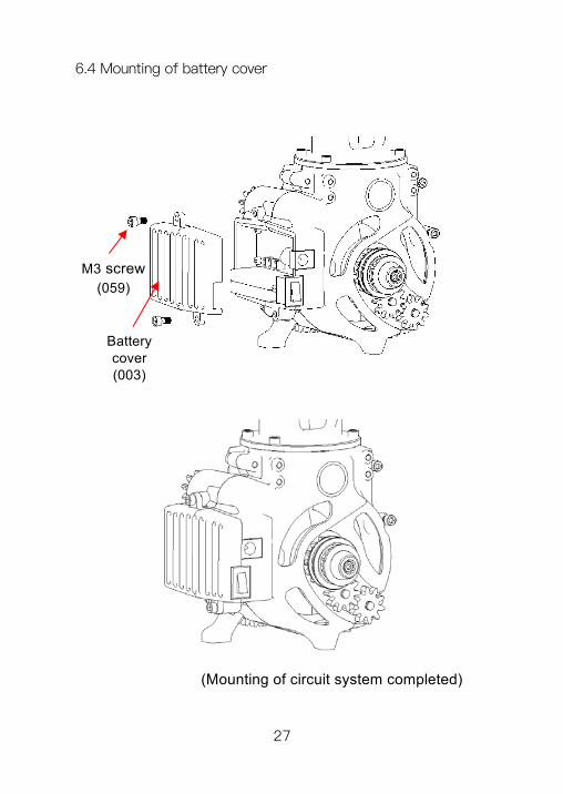
6.4 Mounting of battery cover
(Mounting of circuit system completed)
M3 screw(059)
Battery cover (003)
27
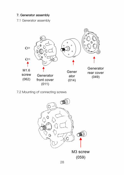
7. Generator assembly
7.1 Generator assembly
Generator (014)
Generator front cover
(011)
Generator rear cover
(049)
M1.6 screw(062)
7.2 Mounting of connecting screws
M3 screw(059)
28
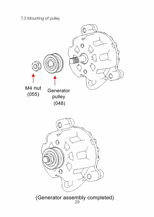
(Generator assembly completed)
Generator pulley (048)
M4 nut (055)
7.3 Mounting of pulley
29
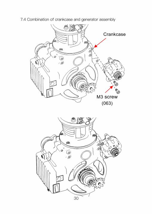
M3 screw(063)
Crankcase
7.4 Combination of crankcase and generator assembly
30
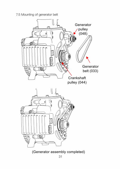
Crankshaft pulley (044)
Generator pulley (048)
Generator belt (033)
(Generator assembly completed)
7.5 Mounting of generator belt
31
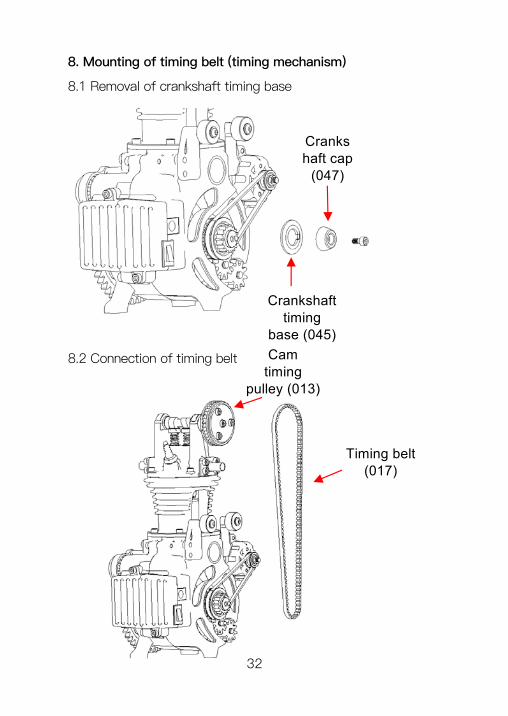
8. Mounting of timing belt (timing mechanism)
8.1 Removal of crankshaft timing base
Crankshaft cap
(047)
Crankshaft timing
base (045)
Timing belt (017)
Cam timing
pulley (013)
8.2 Connection of timing belt
32
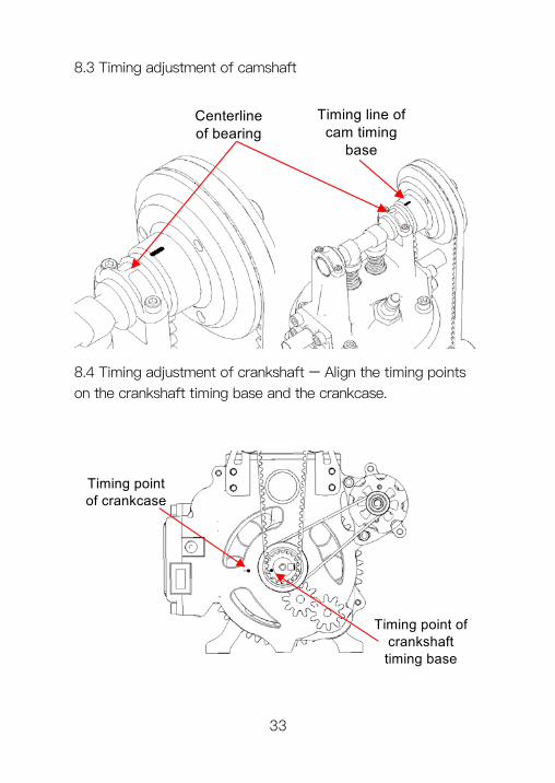
8.3 Timing adjustment of camshaft
Centerline of bearing
Timing line of cam timing
base
8.4 Timing adjustment of crankshaft – Align the timing points on the crankshaft timing base and the crankcase.
Timing point of crankcase
Timing point of crankshaft timing base
33
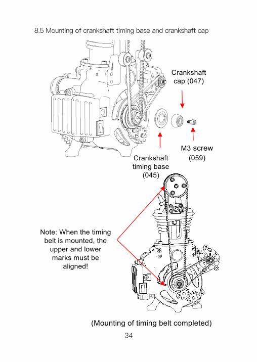
8.5 Mounting of crankshaft timing base and crankshaft cap
(Mounting of timing belt completed)
Crankshaft timing base
(045)
Crankshaft cap (047)
Note: When the timing belt is mounted, the
upper and lower marks must be
aligned!
M3 screw(059)
34
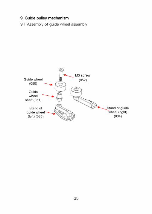
9. Guide pulley mechanism
9.1 Assembly of guide wheel assembly
Guide wheel
shaft (051)
Guide wheel (050)
M3 screw(052)
Stand of guide wheel (left) (035)
Stand of guide wheel (right)
(034)
35
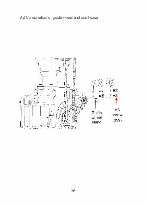
M3 screw(059)
Guide wheel stand
9.2 Combination of guide wheel and crankcase
36
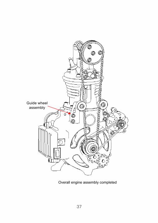
Overall engine assembly completed
Guide wheel assembly
37
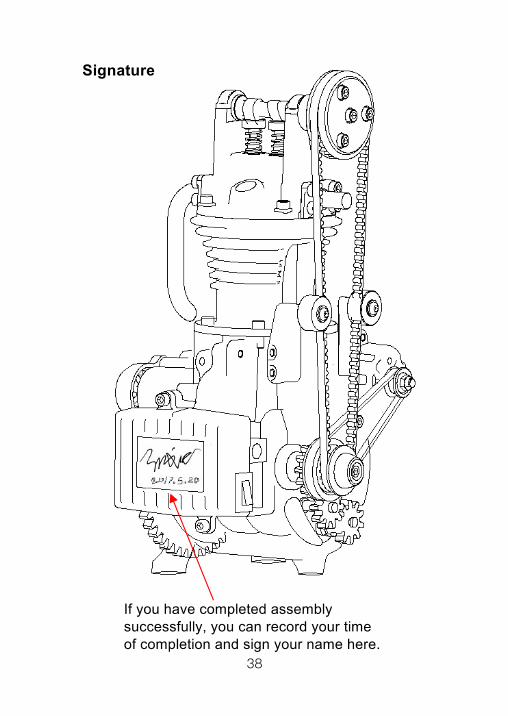
Signature
If you have completed assembly successfully, you can record your time of completion and sign your name here.
38
III. Adjustment of single-cylinder engine
1. Fitting clearancesPay attention to fitting clearances among moving parts. The user is encouraged to adjust clearances slightly using, for example, sandpaper and calipers, based on his/her own observations and judgments.
The main parts are as follows: 1.1 Crankshaft and related moving parts 1.2 Camshaft and related moving parts 1.3 Starting motor and related moving parts 1.4 Piston rod and related moving parts
2. LubricationSince this product is a metallic mechanical model, the absence of lubricant for shaft movement may result in higher frictions or even seizure of parts during movement. The user is encouraged to apply appropriately more lubricant at shaft assembly positions, and observe the effect after lubricant application.
3. Noise reductionShaft moving parts are made of aluminum alloy and have anodized surfaces, and there are loose clearances among some parts, so this product may produce high noise when newly assembly. The user is encouraged to observe and analyze noise producing positions, and may also repair with such tools as sandpaper and file, and apply lubricant to observe the noise reduction effect.
39
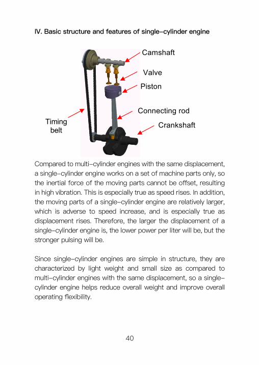
IV. Basic structure and features of single-cylinder engine
Camshaft
Valve
Piston
Connecting rod
CrankshaftTiming belt
Compared to multi-cylinder engines with the same displacement, a single-cylinder engine works on a set of machine parts only, so the inertial force of the moving parts cannot be offset, resulting in high vibration. This is especially true as speed rises. In addition, the moving parts of a single-cylinder engine are relatively larger, which is adverse to speed increase, and is especially true as displacement rises. Therefore, the larger the displacement of a single-cylinder engine is, the lower power per liter will be, but the stronger pulsing will be.
Since single-cylinder engines are simple in structure, they are characterized by light weight and small size as compared to multi-cylinder engines with the same displacement, so a single-cylinder engine helps reduce overall weight and improve overall operating flexibility.
40
When an engine is in a transversal arrangement, the gyroscopic effect of the rotating crankshaft will prevent the motorcycle from tilting laterally to turn; the heavier the crankshaft is, the greater such resistance will be. Since a single-cylinder engine has a short crankshaft, its gyroscopic effect is much weaker, it can tilt laterally leftward or rightward easily, and the driver will feel that the steering handle is very light.
Due to the above features of single-cylinder engines, off-road motorcycles with a displacement of 250CC mostly use single-cylinder engines, as do super-sport motorcycles. Among ordinary motorcycles, small ones with a displacement of below 125CC usually use single-cylinder engines.
41
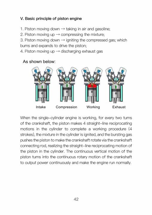
V. Basic principle of piston engine
1. Piston moving down → taking in air and gasoline; 2. Piston moving up → compressing the mixture; 3. Piston moving down → igniting the compressed gas; which burns and expands to drive the piston; 4. Piston moving up → discharging exhaust gas
As shown below:
Intake Compression Working Exhaust
When the single-cylinder engine is working, for every two turns of the crankshaft, the piston makes 4 straight-line reciprocating motions in the cylinder to complete a working procedure (4 strokes), the mixture in the cylinder is ignited, and the bursting gas pushes the piston to make the crankshaft rotate via the crankshaft connecting rod, realizing the straight-line reciprocating motion of the piston in the cylinder. The continuous vertical motion of the piston turns into the continuous rotary motion of the crankshaft to output power continuously and make the engine run normally.
42
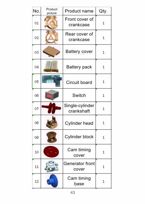
No. Product picture Product name Qty.
Front cover of crankcase
Rear cover of crankcase
Battery cover
Battery pack
Circuit board
Switch
Single-cylinder crankshaft
Cylinder head
Cylinder block
Cam timing cover
Generator front cover
Cam timing base
43
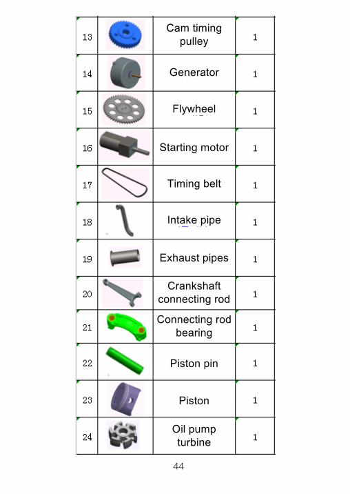
Cam timing pulley
Generator
Flywheel
Starting motor
Timing belt
Intake pipe
Exhaust pipes
Crankshaft connecting rod
Connecting rod bearing
Piston pin
Piston
Oil pump turbine
44
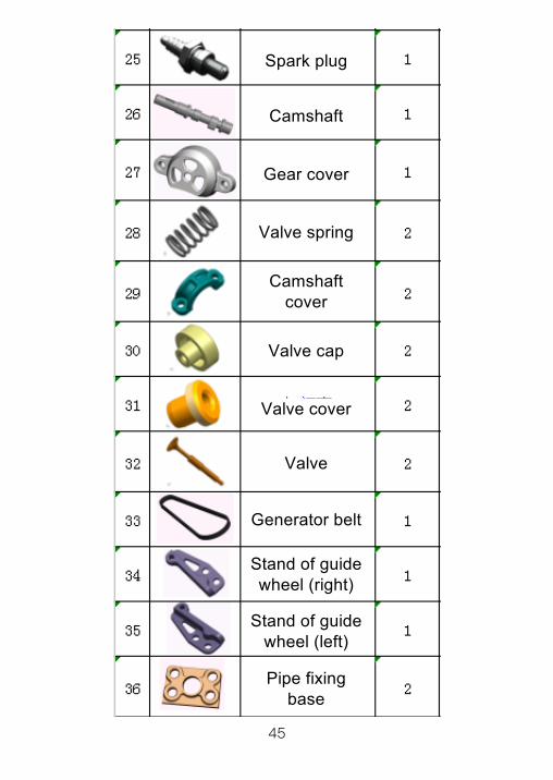
Spark plug
Camshaft
Gear cover
Valve spring
Camshaft cover
Valve cap
Valve cover
Valve
Generator belt
Stand of guide wheel (right)
Stand of guide wheel (left)
Pipe fixing base
45
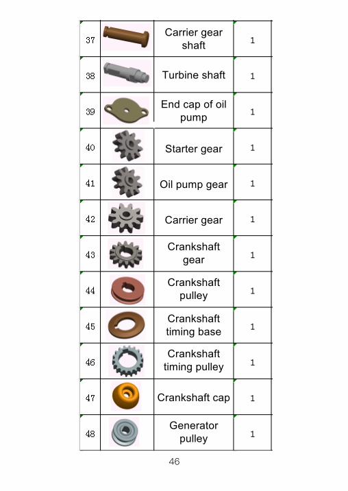
Carrier gear shaft
Turbine shaft
End cap of oil pump
Starter gear
Oil pump gear
Carrier gear
Crankshaft gear
Crankshaft pulley
Crankshaft timing base
Crankshaft timing pulley
Crankshaft cap
Generator pulley
46
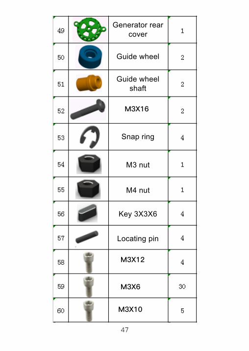
Generator rear cover
Guide wheel
Guide wheel shaft
Snap ring
M3 nut
M4 nut
Key 3X3X6
Locating pin
M3X16
M3X12
M3X6
M3X10
47
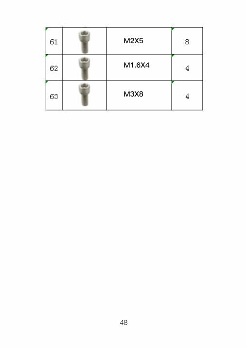
M2X5
M1.6X4
M3X8
48

User Feedback Form
Username: Contact information:User address:
1. Thank you very much for experiencing our assembly
model product. In order to further improve our product
quality, and enhance user experiences, we strongly expect
your valuable comments and suggestions;
2. We will take your comments and suggestions seriously,
and expect to see a change made for you in our future
products;
3. You may contact us by calling us or mailing this form to
us.
Address: 5/F, Baosheng Building, Huangpu District,
Guangzhou
Tel: 400--631--2128
E-mail: [email protected]
Product model:
Suggestions:
49