progress in iter heating and current drive system
TRANSCRIPT

IT/2-1
Progress in ITER Heating and Current Drive System K. Sakamoto1, F. Albajar3, T. Bigelow4, B. Beaumont2, A. Becoulet5, T. Bonicelli3, D. Bora2, D. Campbell2, J. Caughman4, A. Chakraborty7, C. Darbos2, H.Decamps2, G. Denisov8, R. Goulding4, J. Graceffa2, T. Gassmann2, R. Hemsworth2, M. Henderson2, G.T Hoang5, T. Inoue1, J. Jacquinot6, A.Kasugai1, N. Kobayashi2, Ph. Lamalle2, A. Mukherjee7, M. Nightingale9, D. Rasmussen4, S. L. Rao7, G. Saibene3, R. Sartori3, B. Schunke2, P. Sonato10, D. Swain4, K. Takahashi1, M.Tanaka2, A. Tanga2, K. Watanabe1
1 JAEA, 801-1 Mukoyama, Naka-shi, Ibaraki-ken 311-0193, Japan
2 ITER, Joint Work Site, Cadarache, France 3 “Fusion for Energy, c/Josep Pla, N°2, Torres Diagonal Litoral, Edificio B3, 08019 Barcelona, Spain
4 US ITER Project office, Oak Ridge National Laboratory, P.O. Box 2008, 1055 CM, MS 6483, Oak Ridge, TN 37831-6483- USA
5 CEA, IRFM, F-13108 St Paul-lez-Durance, France 6 Cabinet of High Commissioner for Atomic Energy, CEA Gif-sur-Yvette, France
7ITER India, A29, Sector 25, GIDC, Gandhinagar, (Gujarat), India 8Institute of applied physics, 60360 Nizhny Novgorod, Russian Federation
9UKAEA Fusion, Culham, Abingdon, Oxon, OX14 3DB, UK 10Consorzio RFX, Euratom-ENEA Association, Corso Stati Uniti 4, I-35127, Italy
E-mail: [email protected] Abstract Recent progress in the R&D and the design work of plasma heating and current drive (H&CD) technologies for ITER are described. The H&CD systems are composed of 20 MW electron cyclotron (EC), 20 MW ion cyclotron (IC) and 33 MW negative ion based neutral beam (N-NB) systems, and design and R&D work continues for plasma commissioning. Significant progress in R&D during the preceding two years has occurred in EC technology. ITER criteria stipulate a power output of 1 MW for 500 sec with 50 % in efficiency. A recently developed 170 GHz gyrotron has fulfilled these criteria. Using the 170 GHz gyrotron, high power tests of the transmission line and the launcher components have proceeded. These advances indicate clear prospects toward ITER plasma commissioning. For IC technology, a revised launcher design increased the number of current straps from 16 to 24 to optimize the electrical performance. For EC and IC power sources, a new RF building was allocated. N-NB design developments include an agreement to use a multi-aperture multi-grid type (MAMuG) accelerator as a first candidate. Risk mitigation measures for each H&CD system continue to be discussed in the heating technology community under the leadership of the ITER organization. 1. Introduction The plan for the ITER heating and current drive systems is based on a rated power of 73 MW delivered to the plasma in a start up configuration to attain the Q=10 mission. The commissioning of these systems is a key part of the early experimentation in the H/He and D phase. As a reference design, the ITER heating system is composed of three kinds of heating and current drive (H&CD) systems, i.e., 20 MW of electron cyclotron (EC H&CD), 20 MW of ion cyclotron (IC H&CD) and 33 MW of negative ion based neutral beam (N-NB H&CD) systems [1,2,3]. The key technological issues for each system are as follows. Challenges for EC include the development of a 170 GHz 1 MW gyrotron with pulse duration of more than 500 s and an efficiency level exceeding 50 %, and the development of reliable launchers for the equatorial and upper ports. The equatorial launcher (EL) is expected to provide 20 MW towards heating and current drive. Four launchers (UL) of the upper ports will be used mainly for NTM (neo-classical tearing mode) suppression. The roles for IC include bulk ion heating, central current drive, etc. For this system, a commercial

IT/2-1
power source and transmission line components can be utilized. The critical issue is designing a reliable IC launcher, which can accommodate dynamic changes in the edge density profile, which affect the antenna loading. Significant challenges for N-NB include demonstrating a 1 MeV acceleration with the current density of the negative ion beam, 200 A/m2. Current developments have achieved ~800 keV acceleration at ~140 A/m2 during a 0.2 s operation in the test facility (MeV class Test Facility) in JAEA. Also, a neutral beam produced from a negative ion beam of 340 keV, 12.5 A has been successfully injected for >20 s into the JT-60U plasma. In this paper, recent progress in heating and current drive systems is described. 2. Electron Cyclotron Heating and Current Drive (EC H&CD) System The EC system is comprised of power supplies, 170 GHz gyrotrons, transmission lines and two launcher types located in the equatorial (EL) and upper (UL) ports. All of these sub-systems (aside from the power supplies that are already commercially available) are undergoing active R&D programs. In Fig.1, the location of gyrotrons, the transmission line, and launchers are shown. The RF building was newly allocated
Fig.1. Configuration of RF building, assembly hall and torus hall. (a) plane view of RF building (second floor), assembly hall, and torus hall with transmission lines and launchers. (b) 3D view of RF building. Ground and second floors are allocated for power supply, etc., and power sources are placed in third floor. (c) 3D view of the system.
IT/2-1
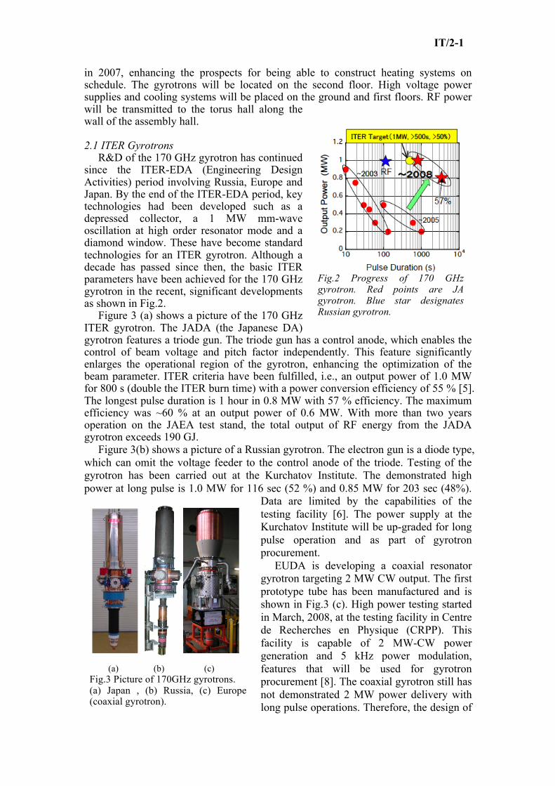
in 2007, enhancing the prospects for being able to construct heating systems on schedule. The gyrotrons will be located on the second floor. High voltage power supplies and cooling systems will be placed on the ground and first floors. RF power will be transmitted to the torus hall along the wall of the assembly hall. 2.1 ITER Gyrotrons R&D of the 170 GHz gyrotron has continued since the ITER-EDA (Engineering Design Activities) period involving Russia, Europe and Japan. By the end of the ITER-EDA period, key technologies had been developed such as a depressed collector, a 1 MW mm-wave oscillation at high order resonator mode and a diamond window. These have become standard technologies for an ITER gyrotron. Although a decade has passed since then, the basic ITER parameters have been achieved for the 170 GHz gyrotron in the recent, significant developments as shown in Fig.2. Figure 3 (a) shows a picture of the 170 GHz ITER gyrotron. The JADA (the Japanese DA) gyrotron features a triode gun. The triode gun has a control anode, which enables the control of beam voltage and pitch factor independently. This feature significantly enlarges the operational region of the gyrotron, enhancing the optimization of the beam parameter. ITER criteria have been fulfilled, i.e., an output power of 1.0 MW for 800 s (double the ITER burn time) with a power conversion efficiency of 55 % [5]. The longest pulse duration is 1 hour in 0.8 MW with 57 % efficiency. The maximum efficiency was ~60 % at an output power of 0.6 MW. With more than two years operation on the JAEA test stand, the total output of RF energy from the JADA gyrotron exceeds 190 GJ. Figure 3(b) shows a picture of a Russian gyrotron. The electron gun is a diode type, which can omit the voltage feeder to the control anode of the triode. Testing of the gyrotron has been carried out at the Kurchatov Institute. The demonstrated high power at long pulse is 1.0 MW for 116 sec (52 %) and 0.85 MW for 203 sec (48%).
Data are limited by the capabilities of the testing facility [6]. The power supply at the Kurchatov Institute will be up-graded for long pulse operation and as part of gyrotron procurement. EUDA is developing a coaxial resonator gyrotron targeting 2 MW CW output. The first prototype tube has been manufactured and is shown in Fig.3 (c). High power testing started in March, 2008, at the testing facility in Centre de Recherches en Physique (CRPP). This facility is capable of 2 MW-CW power generation and 5 kHz power modulation, features that will be used for gyrotron procurement [8]. The coaxial gyrotron still has not demonstrated 2 MW power delivery with long pulse operations. Therefore, the design of
Fig.2 Progress of 170 GHz gyrotron. Red points are JA gyrotron. Blue star designates Russian gyrotron.
(a) (b) (c) Fig.3 Picture of 170GHz gyrotrons. (a) Japan , (b) Russia, (c) Europe (coaxial gyrotron).

IT/2-1
the 1MW gyrotron continued in parallel to the 2 MW gyrotron. The decision of which gyrotron type to prioritize will be made in the EU in 2009. 2.2 Transmission line The transmission line (TL), procured by USDA, uses an HE11 evacuated waveguide to transmit power from the gyrotrons to the launchers. The TL is ~150m in length with 7 to 9 miter bends and an in-line switch to direct the power to either launcher. High power, long pulse experiments at the JAEA testing facility with a transmission line 40m in length with 7 miter bends has demonstrated 92 % transmission efficiency rate from the gyrotron output to the end of the transmission line. This result increases the prospects of an acceptable transmission ratio for ITER.
2.3 EC Launchers The design and R&D of EC launchers are being carried out by JADA and EUDA. A single EL (JADA) is used for central heating and current drive applications and is capable of injecting 20MW over a steering range of 0.<
€
ρT<0.4 [8]. Four ULs (EUDA), each with 8 beam entries, are used for the control of MHD activity over a steering range of 0.3<
€
ρT<0.86 [9]. Both launcher designs replace many of the internal waveguide components with a quasi-optical transmission, thereby reducing the peak power density, cost and complexity of the launchers. Configuration of an EL is shown in Fig.4(a). Three beam lines are injected into the plasma independently by adjusting a movable mirror to achieve the injection angles in the range of 20°~45°. A discussion is underway to change the injection direction of one beam group so that it targets the opposite side, -20°~-45°, in order to tailor the current profile. A preliminary model of a launcher mock-up has been fabricated at JAEA. High power radiation testing will be carried out by using a 170 GHz gyrotron. Figure 4(b) shows the configuration of the upper port launcher. Four launchers will be installed, and 6 MW will be injected from each launcher. At the front of each launcher, two rotational mirrors control the injection angles independently. For each mirror, 3 beam lines are reflected. A tritium boundary window made of a diamond disk is inserted in the waveguide at the input point of the launcher. An automatic cutting/welding tool was developed by FZK to enable window replacement, which
Fig.4 Configuration of equatorial launcher (a), and upper port launcher (b) for EC system.

IT/2-1
also will be available for the equatorial launcher. 3. Ion Cyclotron Heating and Current Drive (IC H&CD) System The IC H&CD will be procured by EUDA, INDA and USDA. The operating frequency range is 40 - 55 MHz, which covers all planned experimental scenarios. Fig.5 shows the configuration of the IC antenna. Power is fed from 8 coaxial transmission lines running from the power sources (Tetrode). The antenna (launcher) design has been modified from a 16-strap array to a 24-strap array to optimize the electrical performance. Three serial straps form an internal triplet. The triplets are fed by 8 power feeds for a total of 24 straps at the front face of the antenna. Each input port features a double vacuum window with a vacuum inter-space thus providing a double tritium boundary. Large uncertainties in the predicted plasma edge density profile elevate the difficulty of coupling the required 20 MW/port for all operation scenarios, frequencies and phases. Optimization proceeds with the goal of obtaining the highest coupling power without exceeding reasonable voltages on the transmission lines. The front face of the antenna will need to match the surrounding blanket modules, both in shape and position, and the current design allows for shimming the antenna to obtain proper positioning. Matching system components are installed in the port cell and/or at the RF source output. ELM resilience is provided by a proper combination of the reflected power during load transients. The 8 sources will use pairs of parallel amplifiers feeding combiners and splitters into 8 coaxial lines to the matching system and antenna. All RF sources and power supplies have been relocated to a dedicated RF building adjacent to the East wall of the assembly hall.
4. Neutral Beam Heating and Current Drive (NB H&CD) system Figure 6 provides a conceptual view of the N-NB system [10]. Over the past few years several important changes have been made to the design of the ITER neutral beam system. The most important changes include the design of the beamline vessel. The new design features a rectangular cross section with an opening at the top to allow for maintenance of beamline components using an overhead crane. Another significant change is the selection of an RF driven negative ion source developed by the EUDA (IPP, Garching) as the baseline design for both the H&CD NB injectors and the diagnostic NB injector [11]. Also important changes are the power supply scheme to use an air-insulated high voltage deck that will allow easier maintenance
(a) (b)
Fig.5 Launcher for IC system. (a) front view without Faraday shield. (b) Cross sectional view.

IT/2-1
and commissioning of the power supply system. Detailed modelling of all beamline components, the beam source and the cryopumps has been carried out. Detailed design work also has started on the 1 MV, 40 A power supply, for which the EUDA will provide the low voltage parts and JADA, the high voltage parts [12]. Collaborative design studies of the power supplies involving the JADA, the EUDA and the IO have proceeded successfully and are expected to result in the issuance of the procurement arrangement for the power supply system in 2008. High energy negative ion beam acceleration and RF driven source development have continued at JAEA (Naka, Japan) and IPP (Garching, Germany), respectively. JAEA has manufactured an ITER-size, large diameter alumina ceramic cylinder (1.56 m), as needed for the ITER high voltage bushing, and JAEA has successfully accelerated 0.32 A of the H- (ion current density 140 A/m2) to 796 keV from a multi-aperture multi-grid type (MAMuG) accelerator. At JAEA, a single aperture, single gap type (SINGAP) accelerator also was tested under an ITER R&D task to compare the two accelerator concepts. In the test, the MAMuG showed better voltage holding, whilst the accelerated electron current was found to be significantly higher from SINGAP than MAMuG. As a result of this testing, MAMuG was chosen as the baseline accelerator for the ITER NBI [13]. IPP has demonstrated stable, 1 hour pulses from an RF driven ion source, and they are now operating the RADI half ITER-size negative ion source. Also a new experiment (ELISE) is to be built at IPP to extract and accelerate negative ions from a half-size source. ITER now plans to have an extensive hydrogen phase and shinethrough wall armour is to be introduced to allow the injection of up to 33 MW of 870 keV H0 beams into low density L-mode hydrogen plasmas.
5. Activities of Risk Mitigation Measures A review in 2007-2008 of the H&CD systems has shown that R&D activities required to attain the specifications and the uncertainty of operating conditions in ITER combine to create considerable managerial risk. The evaluation of the element of risk may lead to the adoption of mitigation measures.
Fig.6 Configuration of N-NB system.

IT/2-1
5.1 NB system As valuable as the ongoing R&D is to the realisation of the ITER neutral beam injectors, it is not sufficient to avoid extensive development of a final full power system for ITER. A Neutral Beam Test Facility (NBTF) is to be built at the CNR, in Padua, Italy, consisting of two test beds: the ion source test facility (ISTF) and the MegaVolt Test Facility (MVTF). The former will be capable of testing to full parameters a full-size ITER ion source, and the latter will test a full-size ITER beam source and beam line components to full performance in both hydrogen and deuterium: accelerating 40 A (46 A) of D- (H-) to 1 MeV (870 keV) for 3600 s, neutralizing the accelerated beam in a gas neutralizer, deflecting the residual ions onto the residual ion dump and measuring the neutral beam power on the calorimeter. The NBTF project will proceed in a manner consistent with the ITER installation/commissioning schedule. 5.2 IC system To inject 20 MW from the antenna, the RF power source needs to provide 3 MW from each transmission line. In this case, a standing voltage level of ~40 kV is anticipated at the straps, which may precipitate a breakdown. To reduce the risk of a breakdown, 2 antennas are recommended which would provide 10 MW injection from 2 equatorial ports. In order to mitigate the risk of a breakdown, high power testing is considered at the ITER site using a port environment test facility prior to installing the machine in the ITER device. 5.3 EC system Fulfilment of the ITER criteria for the gyrotron parameters, foreseen as the most important and most difficult issue in EC technology, has been achieved. In the EC domain, the essential technological difficulty of injecting 20 MW on Day 1 seems to have been removed. However, further efforts are needed to increase system reliability. For the gyrotrons developed by JA and RF, a 1 MW output may be at the margin. To provide a greater margin regarding output power, R&D activity by JA and RF currently focuses on developing a higher oscillation mode. The output power of the gyrotron is utilized to develop the transmission line and launcher components, work which already is underway at a JA testing facility. This R&D will provide a database and information useful in the construction of the EC system. This work will continue at the testing facilities at JA, RF and EU, where >1 MW, CW operation is available. Additionally, it should be noted that gyrotron power is injected from the equatorial launcher “or” the upper port launcher. That is, the upper port launchers are not included in the total count of 73 MW. If additional gyrotrons are prepared for the upper launchers, the additional injection power will supplement the planned 73 MW, thereby constituting effective risk mitigation. 6. Conclusion For the procurement arrangements of H&CD systems of ITER, design and R&D activities have focused the extensive energies of global heating technology community. Some important design changes, such as the new RF building, were proposed and have been adopted in the baseline plan. The present status and issues involving various systems were clarified for ITER construction. For N-NB, progress includes development of an RF ion source, the fabrication of a full-size ceramic insulator, design of a power supply, etc. The MAMuG-type accelerator was adopted. It was recognized that the full-scale NVTF and ISTF are inevitable for ITER-NB

IT/2-1
system construction. Ensuring that NVTF and ISTF are consistent with the ITER construction/commissioning schedule remains an important issue. For IC, progress on antenna design enhances maintenance and better coupling with the plasma. Two equatorial ports are required for reliable 20 MW injection. The EC community has made significant progress in gyrotron development. However, further efforts by all involved parties are needed to ensure the procurement of reliable gyrotrons. The designs and R&D of two types of launchers show progress. The high-power testing of launcher components using the 170 GHz gyrotron will continue as a step toward procurement. It is recognized that the EC system is a primary candidate of increasing power that may be dedicated to risk mitigation. Acknowledgement This report was prepared as an account of work by or for the ITER Organization. The Members of the Organization are the People's Republic of China, the European Atomic Energy Community, the Republic of India, Japan, the Republic of Korea, the Russian Federation, and the United States of America. The views and opinions expressed herein do not necessarily reflect those of the Members or any agency thereof. Dissemination of the information in this paper is governed by the applicable terms of the ITER Joint Implementation Agreement. References [1] “Technical Basis for ITER Final Design Report, 2001”, available on the Internet at www.iter.org. [2] Jacquinot,J., Beaumont, B.,, Hoang,G.T., Kobasyashi,N., Recent Advances of RF Systems for Magnetic Fusion, 17th Topical Conference on radio Frequency Power in Plasmas, AIP conference proceeding 933, p.13, 2007. [3] Bora,D., Beaumont, B., Goulding,R., Jacquinot, J., Kobayashi,N., Swain, D., Tanga,A., RF Heating Needs and Plans for ITER, 17th Topical Conference on radio Frequency Power in Plasmas, AIP conference proceeding 933, p.25, 2007. [4] Hanada,M., Kamada,M., et al., 2008, “Long pulse production of high current D- ion beams in the JT-60 negative ion source”, Rev.Sci.Inst., 79, 02A519. [5] Sakamoto,K., Kasugai,A., Takahashi,K., et al, 2007 “Achievement of robust high-efficiency 1MW oscillation in the hard-self-excitation region by a 170GHz continuous-wave gyrotron”, Nat.Phys., 3., no.6, 411-414. [6] Denisov,G.G., Litvak,A.G., Myasnikov,V.E., et al., 2008, “Development in Russia of high-power gyrotrons for fusion”, Nucl.Fusion, 48 054007. [7] J.-P.Hogge, F.Albajar, A.Alberti, et al, “The Europian 2MW, 170GHz Coaxial Cavity Gyrotron for ITER”, in Conference Digest of the 32nd Int.Conf. IRMMW, Sept.3rd-7th, 2007, Cardiff, UK, 2007 pp.38-40. [8] Takahashi,K., Kajiwara,K., Kobayashi,N., et al, 2008 “Improved design of an ITER equatorial EC launcher”, Nuclear Fusion, 054014. [9] Henderson, M., Heidinger,R., et al., “Review of the ITER EC upper launcher”, 2008, Nucl.Fusion, 054013. [10] Hemsworth, R.S., “Long pulse neutral beam injection”, Nucl. Fusion 43(2003) 851-861. [11] Speth, E., et al., “Overview of the RF source development programme at IPP Garching”, Nuclear Fusion 46(2006)S220-S238. [12] Watanabe, K., et al., “-1 MV DC UHV power supply for ITER NBI”, IT/P7-5, to be presented at this conference. [13] Kashiwagi, M., et al.,”High energy, high current accelerator development for ITER NBI at JADA”, IT-P7-4, to be presented this conference.