reconfiguration generated perturbations in the vector controlled ac
TRANSCRIPT

RECONFIGURATION GENERATED PERTURBATIONS IN THE VECTOR CONTROLLED AC DRIVES
József VÁSÁRHELYI*, Mária IMECS**, János Jób INCZE**, Csaba SZABÓ**
*Department of Automation, University of Miskolc, H-3515 Miskolc, Egyetemváros, Hungary Phone: +36 46 350 877; Fax: +36 46 431 822; E-mail: [email protected]
**Department of Electrical Drives and Robots, Technical University of Cluj-Napoca,
P.O. 1, Box 99, RO-3400 Cluj-Napoca, Romania, Phone/Fax: +40 64 194924; E-mail: [email protected]; [email protected]; [email protected];
ABSTRACT The reconfigurable computing method is applied for the vector control system structure of the tandem converter-fed induction motor operating in normal and failed conditions. The stator-field-oriented voltage control of the VSI working in tandem together with a CSI is changed into rotor-field-oriented current control of the CSI supplying alone the motor, if the VSI should be disconnected. The reconfiguration process introduces perturbations in the vector controlled AC drive. The paper analyses the perturbation effects based on simulation results. They were obtained with the help of a module library in Matlab Simulink special created for implementation into the Field Programmable Gate Arrays (FPGA).
1. INTRODUCTION
In different operating and supply mode the induction motor needs different control strategies. The change of the control structure is required also in the case of the tandem converter AC drive. The term “tandem converter” denotes a recent solution of DC link Static Frequency Converters (SFC), used in medium- and high-power AC drives [1], [2]. It combines the advantages of the two component inverters, with different source character (current and voltage) and different pulse modulation methods. The larger Current-Source Inverter (CSI) is operating in Pulse Amplitude Modulation (PAM) and converts the active power, while the smaller Voltage-Source Inverter (VSI) is working in Pulse Width Modulation (PWM) and supplies the reactive power required for improving the quality of the motor currents in order to compensate them in sine wave form.
Usually the tandem converter is sensible to the failure of the component PWM-VSI. If it fails, it has to be disconnected from the motor terminals and the motor will be fed from the PAM-CSI only. That means the modification of the motor supply character from voltage source to current one [7] [9]. Consequently the structure of the vector control system has to be changed in order to maintain the control of the drive. This is the reason why the reconfigurable computing
method was applied to the control system of the tandem converter-fed induction motor [5], [6].
2. RECONFIGURATION OF THE TANDEM CONVERTER CONTROL SYSTEM
Reconfiguration of the vector control systems was presented in [3], [4]. For each vector control scheme corresponds a state of the configuration state machine supervised by the configuration manager. In [4] was treated the configurable state machine and in [5] the state machine was associated to the reconfiguration of the tandem converter system as is shown in Figure 1. The most sensitive operation mode for the drive is when the VSI fails, and the control structure, looses its voltage-source character.
Power-on Init
STATE 1 Voltage Control with Tandem Converter
STATE 2 Current Control with
CSI Converter
STATE 3 Voltage Control with
VSI Converter
Figure 1. Reconfigurable state machine with
different vector control structures in each state.

12
Refsv
me
Refsε
ωλs
Identified Torque
RefrΨ
Refsqsd λ,v
[is] isd,q
CooT
[D(-λ)]
cosλ sinλ
PWM- VSI
Induction Motor
Phase Transformation
ωr Mechanical Angular Speed
Identified Field Ψs,r
CooT [D(λ)]
Flux Controllers
PhT [A]
Ld
PAM- CSI
Diode Rectifier
AC line
Phase Controlled Rectifier
3xC
VA2
meC
ΨSC
Stator-Flux Computation
isqλs,r
Cd
VSC
VA3 SVM Vd
Coordinate Transformation
Torque Computation
Vector Analyser PWM logic
RefsΨ
Torque Controller
- +
- +- +Ref
rω
Speed Controller
Stator-Voltage Computation
Coordinate Transformation
Refqsd ,v
fs εCSI
VA1 Synchronisation
CSI Current
α
iDC
32π
DC-link Current Controller
- +RefDCi
Refsi
1
2
isd,q
Refqsd ,x
Ψrd,q Ψmd,q
Ψsd,q
ΨrCo
Rotor-Flux Compensation
ΨmCo
Air-gap-Flux Compensation
PhT [A]
[vs]
1 2
vsd,q
ωλs 1
2
Refsd s
i λ
isd,q
Refqsd ,v
Refqsd ,i
Refsγ
1 2
kM kMr
1 2
1 2
Refem
Refrs,Ψ 1
2
Refsd r
i λ
Refsq rs
i,λ
Figure 2. Reconfigurable vector control system for the tandem converter-fed induction motor.
In this undesired case the motor can be fed only by the CSI, and the current-control concept will be applied. In such a situation, the original voltage control structure of the converter cannot correspond any more to the new demands and this justifies the need for reconfiguration. The reconfiguration states from Figure 1 are corresponding to the control structures of the three following supply modes of the induction motor:
• State 1: Tandem converter-fed induction motor with voltage control;
• State 2: Current-Source Inverter-fed motor with current control;
• State 3: Voltage-Source Inverter-fed motor with voltage control.
In order to make possible the reconfiguration and the analysis of the perturbations introduced by the reconfiguration process in the AC drive, let us present two control structures on which the reconfiguration was studied. Figure 2 presents the reconfiguration control structure for State 1 and State 2 above mentioned. The control structure of the stator-field-oriented tandem-fed induction motor has to be reconfigured into a rotor-field-oriented CSI-fed one. Figure 2 also
corresponds to the two different hardware structures implemented in reconfigurable chip (CSoC). The multiplexers (muxes) select the two above mentioned control strategies. In the followings there are described shortly the two corresponding vector control structures. Tandem-converter-fed induction motor. The currents of the AC machine should achieve the sine-wave pattern. The output currents of the tandem converter (i.e. the stator currents) in each phase are to be equal to the fundamental currents of the CSI, and they are:
is_a,b,c = iCSI_a,b,c + iVSI_a,b,c (1)
The current in a phase of the VSI will be the difference of the stator current and the square-wave CSI current in the same phase, as is observable in Figure 3. In the case of the tandem converter the motor in fact is fed in voltage from the VSI, which determines also the CSI voltage at its output. Consequently, from point of view of the motor control, the actuator will be the PWM-VSI and not the PAM-CSI. In such a situation the stator-field orientation (see Figure 2, data-path 1 of the mux) simplifies the cross–effect computation and offers a simpler identification of the orientation field [7], [9].

0.7 0.705 0.71 0.715 0.72 0.725 0.73 0.735 0.74-20
0
20
0.7 0.705 0.71 0.715 0.72 0.725 0.73 0.735 0.74-20
0
20
Time[sec]0.7 0.705 0.71 0.715 0.72 0.725 0.73 0.735 0.74
-20
0
20
is [A]
iCSI [A]
iVSI [A]
Figure 3. Current waveforms at the output of the
tandem converter.
CSI-fed induction motor. The CSI will supply alone the motor if the VSI fails. The VSI will be decoupled from the motor terminals and in the same time instead of it, there will be connected three current filtering capacitors. Due to the current-source character of the CSI, the control system will be reconfigured in rotor-field orientation one (see Figure 2, with data-path 2 selected by the mux). Several reconfiguration methods are known in the literature, but the most suitable method for the vector control systems is the so called “context switching” method mentioned in [8], where the configuration manager switches between the configuration contexts. For each context is allocated a given structure of the vector control system (i.e. each context is a configuration logic state). There are three possible pre-computed structures as was presented in the reconfiguration state diagram in Figure 1. These control structures guarantee that the motor will be controlled with the adequate control strategy if the tandem converter is working in normal conditions or any of the component inverter fails (i.e. fail safe operation).
Due to the expression of the electromagnetic torque, which is depending on the orientation field:
rsqrr
MssqsMe i
kikm λλ ψ
σψ
+==
1, (2)
the torque computation block meC needs also reconfiguration.
3. PERTURBATIONS INTRODUCED BY THE RECONFIGURATION PROCESS
Because of the reconfiguration from one control structure to another (i.e. from tandem CSI+VSI to CSI structure), may appear some unavoidable and undesired transients in the controlled variables of the drive. The transients appear usually as damped oscillatory signals, which persist for relatively short time after the reconfiguration has occurred. The transients were treated for reconfigurable control loops also in [10] and [11]. The problem of the reconfiguration transients is well known by control and audio processing communities, however only a few research reports treat the suppressing of these transients in dynamical reconfigurable systems. There are several solutions for the reduction of reconfiguration transients. Péceli in [10] presented the transient reduction methods treated for filtering problems. The transients in the reconfigurable vector control system need to be carefully analyzed due to the dynamic performance of the drive system. The reconfiguration of a vector control system introduces perturbations in the AC drive, which actually are transients due to the changes of the control structure, i.e. of the hardware structure. The reconfiguration transients for the AC drive act as disturbances and reduce the quality of the drive performances.
0.8 0.85 0.9 0.95 1 1.05 1.1 1.15 1.2
-20
-10
0
10
20
i s[A]
0.8 0.85 0.9 0.95 1 1.05 1.1 1.15 1.2
-10
0
10
i CS
I[A]
0.8 0.85 0.9 0.95 1 1.05 1.1 1.15 1.2
-20
-10
0
10
20
i VS
I / i C
[A]
time[s]
Figure 4. Simulated current waveforms before and after reconfiguration.
For this reason it is important to reduce the reconfiguration transients. In the particular case of the tandem converter controlled AC drive the source of the above mentioned transients, which act as perturbations in the motor, is not only due to the reconfiguration process itself. Let us take the case of the reconfiguration from State 1 to

State 2, the case when the VSI fails. The source of perturbation is also the switching process from the failed VSI to the capacitors. This switching is also part of the reconfiguration but this has directly influences on the stator currents. The overall influence of the reconfiguration, i.e. the introduced perturbations, can be observed in Figure 4. In this case, the perturbations introduced in the AC drive appear mainly because of the reconfiguration from a structure, which has voltage-controlled character (i.e. for the tandem converter-fed motor) to another structure with current-controlled character (i.e. for the CSI-fed-motor) of the drive. As can be observed in Figure 2 the two control structures (CSI+VSI) and (CSI only) have common computing modules. These modules do not need reconfiguration – even if in the two control structures they compute different physical parameters (voltage and/or current intensity). The only exception is perhaps the case of the flux controller, where with the change of the field orientation character (from stator to rotor) the flux reference itself is changed and due to this change, it will generate transients. One solution to avoid this is to use in parallel two flux controllers, one for the stator flux and another for the rotor flux. When the reconfiguration supervisor generates a reconfiguration process, started by the VSI fail, in parallel will switch between the two controllers by using a multiplexer.
4. SIMULATION RESULTS The reconfiguration from the tandem converter-fed structure to the CSI-fed one was simulated using MATLAB-Simulink® environment. The induction motor data are: 5.5 kW, 50 Hz, 220 Vrms, 14 Arms, cosφ = 0.735 and 720 rpm (4 pole-pairs). The motor was started with the tandem converter and after one second it was reconfigured. For the implementation of the reconfigurable vector control structure in Field Programmable Gate Arrays (FPGA), for rapid prototyping and simulation of the reconfiguration process a module library was created. The simulation made with the help of this module library, which can directly implemented in FPGA structures, shows promising results. The control algorithm, implemented in Triscend’s CSoC chip with ARM7 RISC processor, was decomposed in elementary
mathematical operations. This procedure permitted the elaboration of a module library using Matlab Xilinx Toolbox in order to be implemented the control structure into the FPGA chip. Figure 4 show the transients (perturbations) introduced in the stator current, CSI current. It is also observable the transition from the VSI to the capacitors.
00.5
11.5
22.5
-40
-20
0
20
40-40
-30
-20
-10
0
10
20
time[A]isq[A]
i sd[A
]
Figure 5. Motor stator-current space-phasor.
00.5
11.5
22.5
-60
-40
-20
0
20
40-50
-40
-30
-20
-10
0
10
20
30
40
time[s]iCSIq[A]
i CSI
d[A]
Figure 6. CSI output-current space phasor.
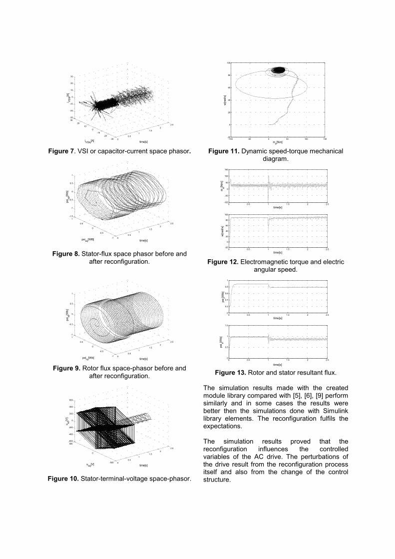
The transient influence on the AC drive – while the stator current waveforms became sinusoidal again is between 0.025s – 0.15s. During this time, the controlled parameters of the motor suffer perturbations. Figure 5 to Figure 13 show these influences on the represented parameters.
00.5
11.5
22.5
-30-20
-100
1020
30-30
-20
-10
0
10
20
30
time[s]iVSIq[A]
i VSId
[A]
Figure 7. VSI or capacitor-current space phasor.
00.5
11.5
22.5
-1
-0.5
0
0.5
1-1.5
-1
-0.5
0
0.5
1
time[s]psisq[WB]
psi sd
[Wb]
Figure 8. Stator-flux space phasor before and
after reconfiguration.
00.5
11.5
22.5
-1
-0.5
0
0.5
1-1
-0.5
0
0.5
1
time[s]psirq[Wb]
psi rd
[Wb]
Figure 9. Rotor flux space-phasor before and
after reconfiguration.
00.5
11.5
22.5
-500
0
500-600
-400
-200
0
200
400
600
time[s]usq[V]
u sd[V
]
Figure 10. Stator-terminal-voltage space-phasor.
-100 -50 0 50 100 150-20
0
20
40
60
80
100
me[Nm]
w[ra
d/s]
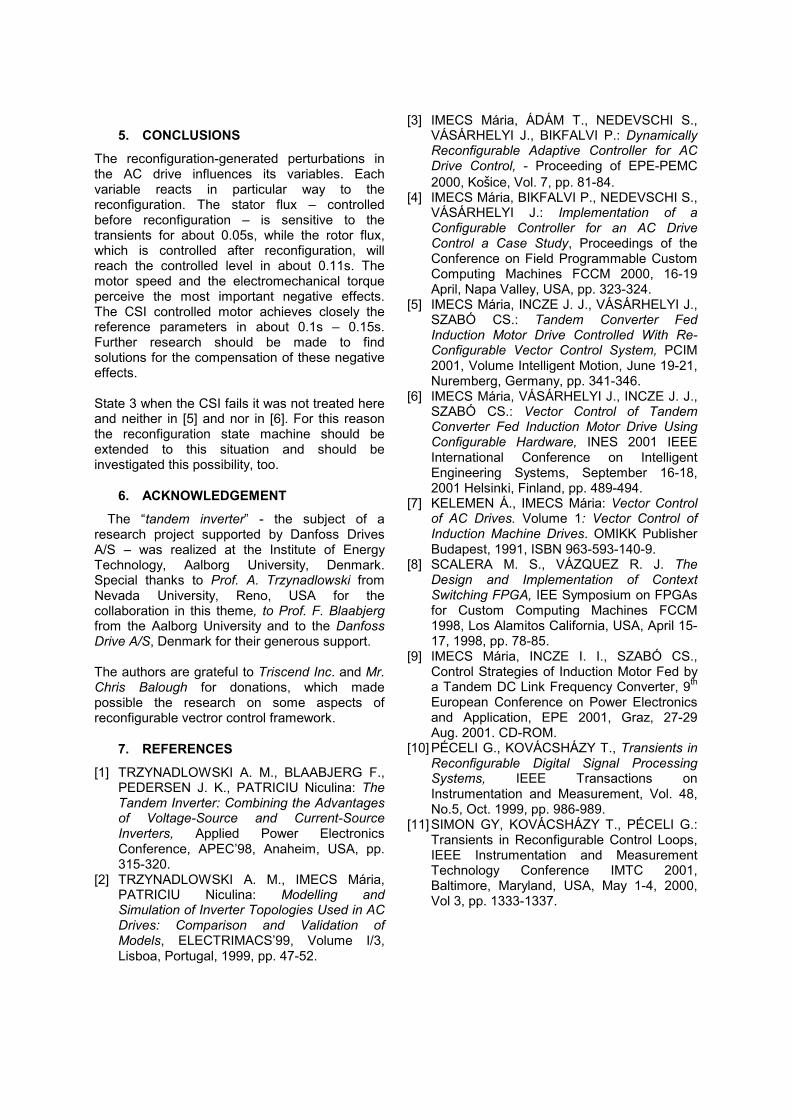
Figure 11. Dynamic speed-torque mechanical
diagram.
0 0.5 1 1.5 2 2.5-100
-50
0
50
100
150
me[N
m]
time[s]
0 0.5 1 1.5 2 2.5-20
0
20
40
60
80
100
time[s]
w[ra
d/s]
Figure 12. Electromagnetic torque and electric
angular speed.
0 0.5 1 1.5 2 2.50
0.2
0.4
0.6
0.8
1
time[s]
psi r[W
b]
0 0.5 1 1.5 2 2.50
0.5
1
1.5
time[s]
psi s[W
b]
Figure 13. Rotor and stator resultant flux.
The simulation results made with the created module library compared with [5], [6], [9] perform similarly and in some cases the results were better then the simulations done with Simulink library elements. The reconfiguration fulfils the expectations. The simulation results proved that the reconfiguration influences the controlled variables of the AC drive. The perturbations of the drive result from the reconfiguration process itself and also from the change of the control structure.
5. CONCLUSIONS
The reconfiguration-generated perturbations in the AC drive influences its variables. Each variable reacts in particular way to the reconfiguration. The stator flux – controlled before reconfiguration – is sensitive to the transients for about 0.05s, while the rotor flux, which is controlled after reconfiguration, will reach the controlled level in about 0.11s. The motor speed and the electromechanical torque perceive the most important negative effects. The CSI controlled motor achieves closely the reference parameters in about 0.1s – 0.15s. Further research should be made to find solutions for the compensation of these negative effects. State 3 when the CSI fails it was not treated here and neither in [5] and nor in [6]. For this reason the reconfiguration state machine should be extended to this situation and should be investigated this possibility, too.
6. ACKNOWLEDGEMENT
The “tandem inverter” - the subject of a research project supported by Danfoss Drives A/S – was realized at the Institute of Energy Technology, Aalborg University, Denmark. Special thanks to Prof. A. Trzynadlowski from Nevada University, Reno, USA for the collaboration in this theme, to Prof. F. Blaabjerg from the Aalborg University and to the Danfoss Drive A/S, Denmark for their generous support.
The authors are grateful to Triscend Inc. and Mr. Chris Balough for donations, which made possible the research on some aspects of reconfigurable vectror control framework.
7. REFERENCES [1] TRZYNADLOWSKI A. M., BLAABJERG F.,
PEDERSEN J. K., PATRICIU Niculina: The Tandem Inverter: Combining the Advantages of Voltage-Source and Current-Source Inverters, Applied Power Electronics Conference, APEC’98, Anaheim, USA, pp. 315-320.
[2] TRZYNADLOWSKI A. M., IMECS Mária, PATRICIU Niculina: Modelling and Simulation of Inverter Topologies Used in AC Drives: Comparison and Validation of Models, ELECTRIMACS’99, Volume I/3, Lisboa, Portugal, 1999, pp. 47-52.
[3] IMECS Mária, ÁDÁM T., NEDEVSCHI S., VÁSÁRHELYI J., BIKFALVI P.: Dynamically Reconfigurable Adaptive Controller for AC Drive Control, - Proceeding of EPE-PEMC 2000, Košice, Vol. 7, pp. 81-84.
[4] IMECS Mária, BIKFALVI P., NEDEVSCHI S., VÁSÁRHELYI J.: Implementation of a Configurable Controller for an AC Drive Control a Case Study, Proceedings of the Conference on Field Programmable Custom Computing Machines FCCM 2000, 16-19 April, Napa Valley, USA, pp. 323-324.
[5] IMECS Mária, INCZE J. J., VÁSÁRHELYI J., SZABÓ CS.: Tandem Converter Fed Induction Motor Drive Controlled With Re-Configurable Vector Control System, PCIM 2001, Volume Intelligent Motion, June 19-21, Nuremberg, Germany, pp. 341-346.
[6] IMECS Mária, VÁSÁRHELYI J., INCZE J. J., SZABÓ CS.: Vector Control of Tandem Converter Fed Induction Motor Drive Using Configurable Hardware, INES 2001 IEEE International Conference on Intelligent Engineering Systems, September 16-18, 2001 Helsinki, Finland, pp. 489-494.
[7] KELEMEN Á., IMECS Mária: Vector Control of AC Drives. Volume 1: Vector Control of Induction Machine Drives. OMIKK Publisher Budapest, 1991, ISBN 963-593-140-9.
[8] SCALERA M. S., VÁZQUEZ R. J. The Design and Implementation of Context Switching FPGA, IEE Symposium on FPGAs for Custom Computing Machines FCCM 1998, Los Alamitos California, USA, April 15-17, 1998, pp. 78-85.
[9] IMECS Mária, INCZE I. I., SZABÓ CS., Control Strategies of Induction Motor Fed by a Tandem DC Link Frequency Converter, 9th European Conference on Power Electronics and Application, EPE 2001, Graz, 27-29 Aug. 2001. CD-ROM.
[10] PÉCELI G., KOVÁCSHÁZY T., Transients in Reconfigurable Digital Signal Processing Systems, IEEE Transactions on Instrumentation and Measurement, Vol. 48, No.5, Oct. 1999, pp. 986-989.
[11] SIMON GY, KOVÁCSHÁZY T., PÉCELI G.: Transients in Reconfigurable Control Loops, IEEE Instrumentation and Measurement Technology Conference IMTC 2001, Baltimore, Maryland, USA, May 1-4, 2000, Vol 3, pp. 1333-1337.