report type deliverable d6.1.2 report name case study ... · report name case study model and...
TRANSCRIPT

Grant Agreement 260057
Model-based Analysis & Engineering of Novel Architectures for
Dependable Electric Vehicles
Report type Deliverable D6.1.2
Report name Case study model and specification
Dissemination level PU
Status Final
Version number 3.1
Date of preparation 2014-02-18

MAENAD D6.1.2 Grant Agreement 260057
2014 The MAENAD Consortium 2 (53)
Authors
Editor E-mail
Stefano Cerchio [email protected]
Authors E-mail
Dejiu Chen [email protected]
Frank Hagl [email protected]
Henrik Lönn [email protected]
Sandra Torchiaro
Reviewers E-mail
Renato Librino [email protected]
The Consortium
Volvo Technology Corporation (S) Centro Ricerche Fiat (I)
Continental Automotive (D) Delphi/Mecel (S) 4S Group (I)
ArcCore AB (S) MetaCase (Fi) Systemite (SE) CEA LIST (F)
Kungliga Tekniska Högskolan (S) Technische Universität Berlin (D) University of Hull (GB)

MAENAD D6.1.2 Grant Agreement 260057
2014 The MAENAD Consortium 3 (53)
Revision chart and history log
Version Date Reason
0.1 2011-03-08 First internal release
0.2 2011-05 Minor changes
0.3 2011-06-15 Introduction updated
1.0 2011-06-30 Intermediate Release
1.0.1 2011-08-30 BBW Diagrams updated
1.0.2 2012-06-18 Integrated new inputs for “Range evaluation” and BBW model
1.0.4 2012-06-18 Fixed references errors – Document review
1.0.5 2012-06-29 Propulsion model updated
2.0 2012-06-30 Second release corresponding to M21 status
2.0.1 2012-08-31 Minor adjustments for P2
3.0 2013-03-27 M30 Release based on review by 4SG. Variability chapter added
3.1 2014-02-18 Final Release reflecting M42 status
Approval Date
Henrik Lönn 20140221

MAENAD D6.1.2 Grant Agreement 260057
2014 The MAENAD Consortium 4 (53)
List of abbreviations
Table of terms and abbreviations used in this document
Abbreviation Description
BEV Battery Electric Vehicles
CAN Controller Area Network
ECU Electronic Control Unit
EVC Electric Vehicle Controller
FEV Fully Electric Vehicles
HMI Human-Machine Interface
HVJB High Voltage Junction Box
PE Power Electronic

MAENAD D6.1.2 Grant Agreement 260057
2014 The MAENAD Consortium 5 (53)
Table of contents
Authors ............................................................................................................................................................... 2
Revision chart and history log ............................................................................................................................ 3
List of abbreviations ............................................................................................................................................ 3
Table of contents ................................................................................................................................................ 5
List of figures ...................................................................................................................................................... 6
1 Introduction ................................................................................................................................................. 8
Document Overview ..................................................................................................................................... 10
2 Case studies modelling ............................................................................................................................ 11
2.1 Propulsion and power distribution .................................................................................................... 11
2.1.1 Vehicle level .............................................................................................................................. 11
2.1.2 Analysis level ............................................................................................................................ 13
2.1.3 Design Level ............................................................................................................................. 14
2.1.4 Extension Model ....................................................................................................................... 17
Mode and range management ..................................................................................................................... 27
2.1.5 Vehicle level .............................................................................................................................. 28
2.1.6 Analysis Level ........................................................................................................................... 28
2.1.7 Design Level ............................................................................................................................. 31
2.1.8 Implementation Level ............................................................................................................... 34
2.1.9 Extension Model ....................................................................................................................... 34
2.2 Regenerative Braking System .......................................................................................................... 41
2.2.1 Overall Model ............................................................................................................................ 41
2.2.2 Vehicle level .............................................................................................................................. 42
2.2.3 Analysis Level ........................................................................................................................... 45
2.2.4 Design Level ............................................................................................................................. 47
2.2.5 Implementation Level ............................................................................................................... 51
3 Conclusion ................................................................................................................................................ 53

MAENAD D6.1.2 Grant Agreement 260057
2014 The MAENAD Consortium 6 (53)
List of figures
Figure 1-1: EAST-ADL Abstraction levels ...................................................................................... 10
Figure 2-1: Vehicle Feature Model of the “Propulsion” subsystem ................................................. 12
Figure 2-2: Propulsion - Analysis Function Types ......................................................................... 13
Figure 2-3 Propulsion - Functional Analysis Architecture .............................................................. 13
Figure 2-4: Propulsion - Design Function Types ............................................................................ 14
Figure 2-5: Propulsion - example of FDA realized in different development environment. ............ 15
Figure 2-6: Propulsion - Hardware Architecture Types .................................................................. 16
Figure 2-7: example of HDA realized in different development environment .................................. 17
Figure 2-8: Propulsion - Requirements Model .............................................................................. 18
Figure 2-9: Propulsion - example of requirements hierarchy ......................................................... 18
Figure 2-10: Propulsion – Link between requirements and architectural artefacts ......................... 18
Figure 2-11: Dependability model – Hazard analysis of the Propulsion subsystem ........................ 21
Figure 2-12 EV and EVS communication IEC related .................................................................... 23
Figure 2-13 CHADEMO connector and interface ........................................................................... 23
Figure 2-14 Feature model structure ............................................................................................. 24
Figure 2-15 IEC Feature Model ..................................................................................................... 25
Figure 2-16 SAE Feature Model .................................................................................................... 25
Figure 2-17:Propulsion – V&V modeling ........................................................................................ 26
Figure 2-18. Vehicle Feature Model of the “mode and range management” .................................. 28
Figure 2-19: Embedded Range Problem Solver on Analysis level ................................................. 29
Figure 2-20: Dynamic View of Range Problem Solver (including data flows) ................................. 30
Figure 2-21: Dynamic View of Range Problem Solver Dialog (including data flows) ...................... 31
Figure 2-22 Overall Design of Comfort Range Balancer with subsystems ..................................... 32
Figure 2-23: Embedded Range Problem Solver on Design Level .................................................. 32
Figure 2-24: Internal View of Range Problem Solver ..................................................................... 33
Figure 2-25: Hardware Design Architecture of Comfort Range Balancer ....................................... 34
Figure 2-26: “Mode and range management” Activity diagram UML .............................................. 35
Figure 2-27: Modelica behavioural description .............................................................................. 36
Figure 2-28: Yakindu State Machine .............................................................................................. 36
Figure 2-29: AUTOSAR internal behaviour of Range Problem Solver ........................................... 37
Figure 2-30: C-Code: behaviour on implementation level .............................................................. 38
Figure 2-31: TADL constraints in ARtext ....................................................................................... 39
Figure 2-32: Requirements in excel table ...................................................................................... 40
Figure 2-33: An overview of packages of an EAST-ADL model in Papyrus. .................................. 41
Figure 2-34: The braking electrical/electronic system and its environment in Papyrus. .................. 42
MAENAD D6.1.2 Grant Agreement 260057
2014 The MAENAD Consortium 7 (53)
Figure 2-35: An overview of system model and related EAST-ADL packages for the specifications of requirements, V&V cases, and the annotations of variability and other non-functional constraints in Papyrus. .................................................................................................................................... 42
Figure 2-36: Vehicle Feature Model of the Regenerative Braking System in Papyrus. .................. 43
Figure 2-37: A model of braking performance requirements in Papyrus. ....................................... 44
Figure 2-38: Allocations of braking requirements on vehicle features in Papyrus. ......................... 44
Figure 2-39: Advanced Braking feature and the specification of its functional realizations in Papyrus. ........................................................................................................................................ 45
Figure 2-40: Regenerative Braking Control feature and the specification of its functional realizations in Papyrus. ................................................................................................................. 45
Figure 2-41: Functional Analysis Architecture specification of the Regenerative Braking System in Papyrus. ........................................................................................................................................ 46
Figure 2-42: Connecting functional analysis functions with environment in Papyrus. ..................... 47
Figure 2-43. Synchronization and End-to-end timing from pedal to brake actuators ...................... 47
Figure 2-44. Functional Design Architecture of the Regenerative Braking System in Papyrus. ...... 48
Figure 2-45. Period times of functions ........................................................................................... 48
Figure 2-46. Functional Design Architecture with end-to-end timing .............................................. 49
Figure 2-47. Functional Design Architecture with end-to-end timing .............................................. 50
Figure 2-48: Hardware Design Architecture of the Braking System in Papyrus. ............................. 51
Figure 2-49: Function-to-node Allocation in the Braking System in Papyrus. ................................. 51
Figure 2-50. AUTOSAR Software Component Template of the Braking System ........................... 52
Figure 2-51. AUTOSAR Software Component Template of the Braking System ........................... 52

MAENAD D6.1.2 Grant Agreement 260057
2014 The MAENAD Consortium 8 (53)
1 Introduction
The main goal of this document is to describe all the modelling aspects that have been performed within WP6 on the selected case studies, and a preliminary overview about the steps carried out towards the analysis of the project outcomes.
To meet the project objective, three different case studies related to Full Electric Vehicle application have been proposed to exercise the modelling aspect, modelling techniques and analysis framework
power and signal distribution subset of a FEV with the associated interlock functionality for safety features, and the driving mode selection management,
regenerative braking systems based on an innovative brake by wire distributed architecture.
Driving mode management for electric vehicle, with enhanced power and energy supervision algorithm to support the driver in critical range situation, as well the related HMI to interact with the driver

MAENAD D6.1.2 Grant Agreement 260057
2014 The MAENAD Consortium 9 (53)
The availability of different case studies guarantee a major degree of confidence about the completeness of the analysis, with the main goal to demonstrate feasibility and effectiveness of Maenad main artefacts on evaluating key FEV functions and concepts in terms of: • performance and dependability of design proposals • compliance with FEV standards and ISO 26262 standards, • ability to interface with the 14V architecture, • electrical isolation in accordance with high voltage standards,
MAENAD D6.1.2 Grant Agreement 260057
2014 The MAENAD Consortium 10 (53)
Document Overview
The three case studies have been modelled using the methods and tools developed in the Maenad project.
The Maenad development framework heavily relies on EAST-ADL modelling language, a domain specific language for the design of automotive electronic architecture that has been settled and enriched in various phases within different European research projects.
In the context of the MAENAD project, the original languages, design methodology and related tools for the development and evaluation of complex automotive architectures further grow to support and capture specifics aspect related to the design of Electric vehicles, while evolving to maintain compatibility with existing commercial tools and design standard.
With this background, the structure of the document reflects and embraces the approach that the modelling languages provide to organize and represent the engineering information related to a particular system
Models are organized in different levels of abstraction, each of which provides a particular view of the entire vehicle embedded system.
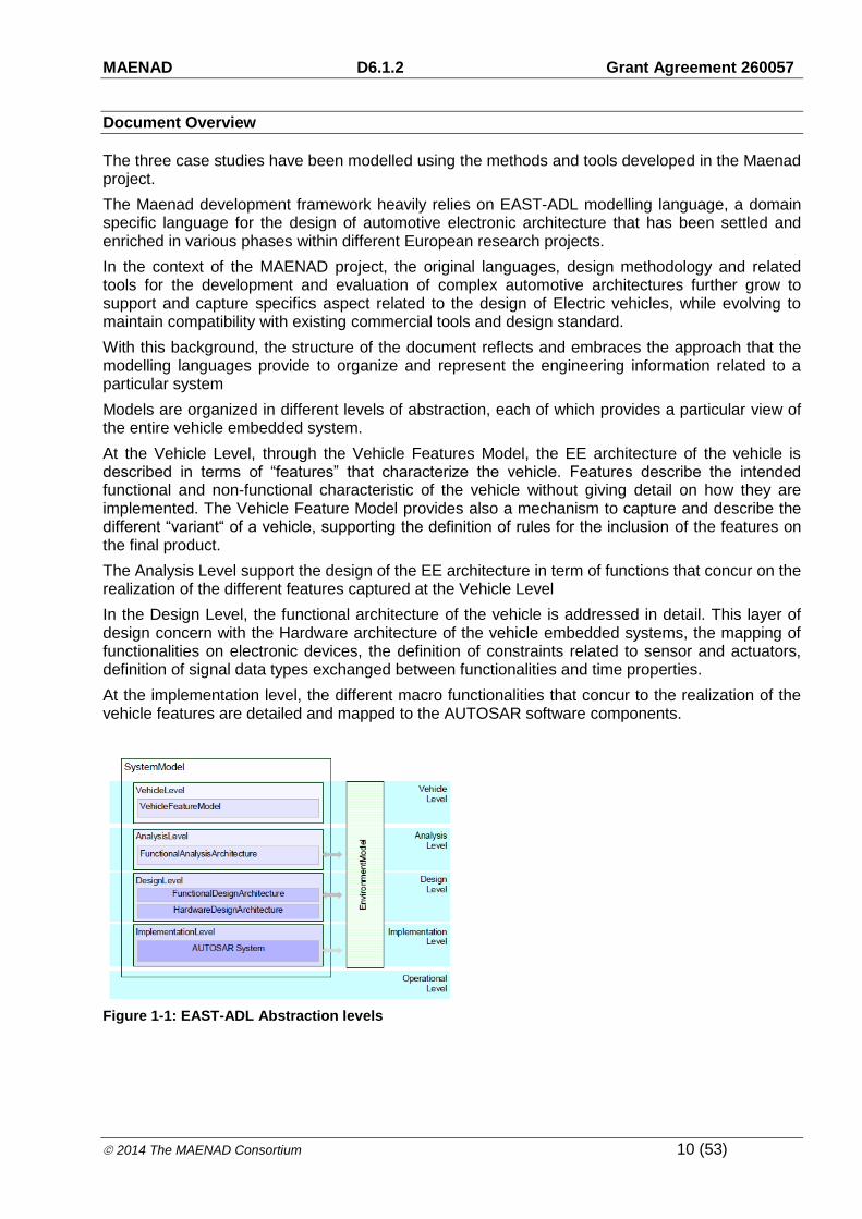
At the Vehicle Level, through the Vehicle Features Model, the EE architecture of the vehicle is described in terms of “features” that characterize the vehicle. Features describe the intended functional and non-functional characteristic of the vehicle without giving detail on how they are implemented. The Vehicle Feature Model provides also a mechanism to capture and describe the different “variant“ of a vehicle, supporting the definition of rules for the inclusion of the features on the final product.
The Analysis Level support the design of the EE architecture in term of functions that concur on the realization of the different features captured at the Vehicle Level
In the Design Level, the functional architecture of the vehicle is addressed in detail. This layer of design concern with the Hardware architecture of the vehicle embedded systems, the mapping of functionalities on electronic devices, the definition of constraints related to sensor and actuators, definition of signal data types exchanged between functionalities and time properties.
At the implementation level, the different macro functionalities that concur to the realization of the vehicle features are detailed and mapped to the AUTOSAR software components.
Figure 1-1: EAST-ADL Abstraction levels

MAENAD D6.1.2 Grant Agreement 260057
2014 The MAENAD Consortium 11 (53)
2 Case studies modelling
2.1 Propulsion and power distribution
The “Propulsion and power distribution” subsystem represent a typical powertrain solution and architecture for BEV.
This case study has been developed with the main purpose of demonstrate and experiment the support given by the language and the related tools developed/enhanced during the MAENAD project for the design and development of EVs. In this context, the developed subsystem does not represent a fully-fledged real EV powertrain, but has the aim to provide elements to exploit the modelling aspects at the different abstraction level and to serve as an input for the analysis and synthesis tools.
The main architecture is composed by an electric motor and the inverter acting as a torque and speed controller. The propulsion is managed and supervised by an Electronic Control Unit (EVC) that collects the user request provided through the gas/brake pedal and the “Driving Mode Selector”, and send a torque request to the Electric Engine taking into account the feedback about the working point of the different apparatus, the driving condition, and the safety constraints.
The EVC is also responsible for the selection of the “Driving mode” among the available states. Even if an electric car does not need a gear for transmission for varying shaft ratios like in ICE, it has to be able to change direction forward and backward electrically or provide additional working mode similar to automated transmission like “Park”, where a mechanical latch is engaged to prevent vehicle movement, or “Neutral”, where the torque request from the EVC to the electric motor is set to zero independently from the user action on the gas pedal.
The switch between the different states can come directly from the HMI inputs, but also from other information drawn from the vehicle (for example the EVC can override the request coming from the user on critical fault conditions or for safety reason to place the vehicle in a safe condition or to prevent misuse). The state changes is mainly involved at the software level and results in different torque management behavior.
Considering the Power Distribution Network, the energy flow from the battery pack to the electrified auxiliaries through a distribution box (HVJB), that provides electrical features to prevent Electrical Hazard.
For the “Propulsion and power distribution” case study, a physical prototype of the subsystem have been realized as a part of the project, as well as a physical test bench capable to inject fault on main components, to verify the support of the language and tool for the validation activities performed during the development phases.
Model development have been carried out under two different development environment: MetaEdit+ and Papyrus
2.1.1 Vehicle level
The main feature of a fully electric vehicle (FEV) is the using of high voltage electrical energy for driving, provided by a battery. The High Voltage Junction Box is distributing the energy to different consumers or providers. The main consumer is the drivetrain, consisting of power electronic and e-machine. But there are others as heater or compressor. These consumers are not part of this model. The energy is provided by a charger. There might be different chargers connected to the high voltage junction box. They are not modelled either.
It has to be assured that no one touches high voltage unintentionally. Furthermore it is important to supervise the proper function of all high voltage connections. For this reason the interlock line is established. That is every high voltage connector has two additional contacts which are connected

MAENAD D6.1.2 Grant Agreement 260057
2014 The MAENAD Consortium 12 (53)
to each other as long as the connector is plugged in completely. As soon as one connector is released the interlock is opened. When this occurs, the high voltage supply is disconnected immediately.
This function is required to assure that persons do not have contact to the high voltage under all circumstances. Maybe a connector is damaged after an accident. Then the high voltage supply has to be stopped to avoid any further damage of persons. It is dangerous to stop the electrical machine in case the interlock line was opened by mistake. If this happens during a takeover manoeuvre the vehicle will lose driving energy immediately.
As the Electric Vehicle Controller is the main controller for many powertrain functions of an electric vehicle. It provides the information to feed the interlock line to the HVJB. This is done by a dedicated signal on the connection Feed interlock between EVC and HVJB. Thus the EVC is the beginning of the interlock line. Furthermore the EVC is then the endpoint of the interlock line – connection Evaluate interlock between HVJB and EVC. In the EVC the evaluation of the status of the interlock line is done. As a result of this evaluation the EVC may decide to shut down the high voltage which is done with the connection PowerSourceEnable and to stop the torque request from the Power electronic.
Figure 2-1: Vehicle Feature Model of the “Propulsion” subsystem
As described in previous chapter, the EV has to be able to change direction forward and backward electrically. Furthermore it has to be possible to bring the vehicle in a parking mode. That is why a Driving Mode Selector (PRND) is necessary. To accept a certain indication for a driving mode by the driver the brake signal, the speed and e-propulsion status of the vehicle have to be evaluated.
The gears PRND are set according to the drivers wish and status (velocity and status of propulsion and brake). The Torque control needs to know the status of the selected Driving mode to
MAENAD D6.1.2 Grant Agreement 260057
2014 The MAENAD Consortium 13 (53)
2.1.2 Analysis level
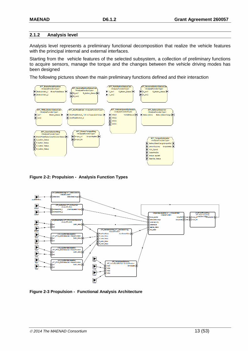
Analysis level represents a preliminary functional decomposition that realize the vehicle features with the principal internal and external interfaces.
Starting from the vehicle features of the selected subsystem, a collection of preliminary functions to acquire sensors, manage the torque and the changes between the vehicle driving modes has been designed
The following pictures shown the main preliminary functions defined and their interaction
Figure 2-2: Propulsion - Analysis Function Types
Figure 2-3 Propulsion - Functional Analysis Architecture

MAENAD D6.1.2 Grant Agreement 260057
2014 The MAENAD Consortium 14 (53)
2.1.3 Design Level
Functional Design Architecture
A step forward in the design of the case study have been done using the “Functional Design Architecture”, that in this specific case refine the preliminary design of the system adding further details in terms of functional decomposition, flow ports and provides implementation details of functional mapping on HW items through allocations.
Figure 2-4: Propulsion - Design Function Types

MAENAD D6.1.2 Grant Agreement 260057
2014 The MAENAD Consortium 15 (53)
Figure 2-5: Propulsion - example of FDA realized in different development environment.
Hardware Design Architecture
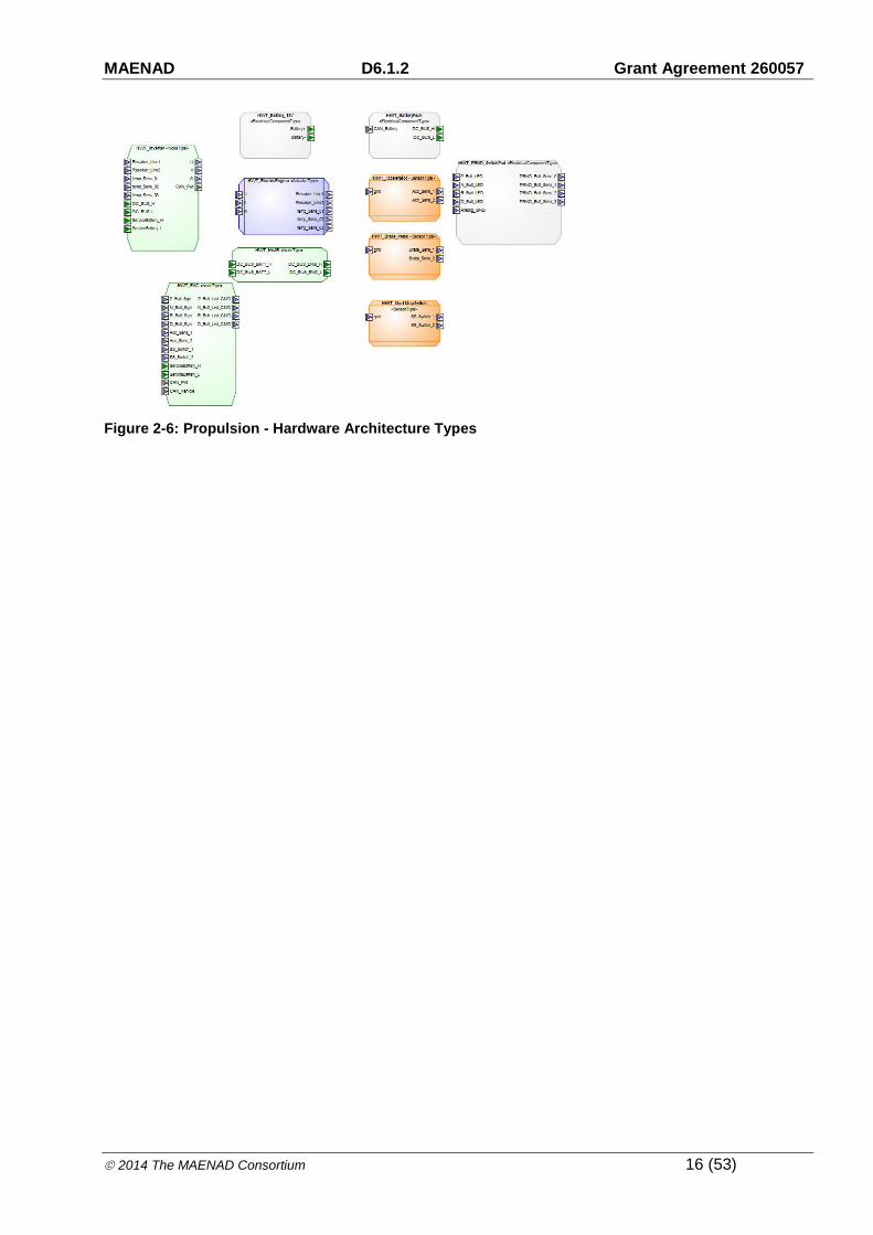
The following Hardware Design Architecture shown in Error! Reference source not found. describes the hardware realization for the features explained in chapter 2.1.1.
For all parts only the connectors relevant for this model are shown.
The battery system, delivers the energy which is guided though the High voltage junction box to the power electronic. The power electronic transforms the DC voltage to be provided to the EV motor.
The electric vehicle controller is the main controller for many powertrain functions of an electric vehicle. All functions of this model run at this controller.
The sensors in this model are needed for the selection of the driving mode.
MAENAD D6.1.2 Grant Agreement 260057
2014 The MAENAD Consortium 16 (53)
Figure 2-6: Propulsion - Hardware Architecture Types
MAENAD D6.1.2 Grant Agreement 260057
2014 The MAENAD Consortium 17 (53)
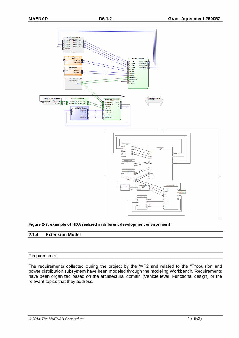
Figure 2-7: example of HDA realized in different development environment
2.1.4 Extension Model
Requirements
The requirements collected during the project by the WP2 and related to the “Propulsion and power distribution subsystem have been modeled through the modeling Workbench. Requirements have been organized based on the architectural domain (Vehicle level, Functional design) or the relevant topics that they address.

MAENAD D6.1.2 Grant Agreement 260057
2014 The MAENAD Consortium 18 (53)
Figure 2-8: Propulsion - Requirements Model
Traceability and dependency between the requirements at the different abstraction levels have been formulated through the "Derive","Refine" relationship.
Figure 2-9: Propulsion - example of requirements hierarchy
Specific models have been created to show the link between collected requirements and other architectural elements (function, hardware) that realize them, formulated adopting the “Satisfy” relation.
Figure 2-10: Propulsion – Link between requirements and architectural artefacts
Dependability

MAENAD D6.1.2 Grant Agreement 260057
2014 The MAENAD Consortium 19 (53)
One of the goals of the WP6 is to evaluate the ability of MAENAD to support ISO 26262 safety process and safety concepts, as well as their integration with other aspects of system development. A preliminary step of the evaluation activity consists on the application of the main functional safety activities (Item definition, hazard analysis and risk assessment) Item Definition
The first fundamental step of the safety life-cycle is the identification and description of the Item under analysis, and to develop an adequate understanding of it. This is an essential step, since the subsequent phases of safety design flow are based on the item definition and the safety concept is derived from it.
To have a satisfactory understanding of the Item, is essential to properly analyse the item itself in terms of input(s)/output(s), functionality, interfaces and, how the item interacts with the vehicle and/or with the environment. In this context, all the design activities ranging from the analysis level to the design level provides a clear understanding on the main functions, their interactions and the flow of information between them
Hazard Analysis and Risk Assessment
In the following table the main results coming from the Risk assessment, in terms of maximum level of risk associated to each hazardous event, have been summarized. The table includes the main hazards related the propulsion part, useful for testing on test bench.
Hazard
Scenario
Hazardous Event
ASIL
Id Description Id Description
H1 Unexpected forward movement
- VehicleSpeed=0; - Key Status = ON - ePRND Status = N; - Driver on board; - Vehicle in a queue at the traffic light, with interposed pedestrian.
HE1.1
Unexpected forward movement of the vehicle, when vehicle is stopped in a queue (with interposed pedestrian), due to an unwanted application of positive torque.
C
H1 Unexpected forward movement
- VehicleSpeed=0; - Key Status = ON - ePRND Status = N; - Driver out of board; - hand brake disengaged.
HE1.2 Unexpected forward movement of the vehicle, when vehicle is left by the driver with N selected, due to an unwanted application of positive torque.
C
H1 Unexpected forward movement
- VehicleSpeed=0; - Key Status = ON; - ePRND Status = N; - Driver out of board; - vehicle pluggedIn; - hand brake disengaged.
HE1.3
Unexpected forward movement of the vehicle, when vehicle is in charging mode (pluggedIn) with N selected, due to an unwanted application of positive torque.
D
H2 Sudden acceleration of vehicle
- Medium VehicleSpeed; - Key Status = ON; - ePRND Status = N; - urban scenario (Driving on urban roads in suitable traffic condition (e.g. approaching traffic light with N selected).
HE2 .1 Sudden acceleration of vehicle when vehicle is at medium speed, with N selected.
A

MAENAD D6.1.2 Grant Agreement 260057
2014 The MAENAD Consortium 20 (53)
H2 Sudden acceleration of vehicle
- creeping threshold < VehicleSpeed < 50 kph; - brake bedal = OFF; - accelerator pedal = OFF; - ePRND Status = D; - urban scenario: Vehicle in natural deceleration , near to pedestrian crossing (with pedestrian is crossing the road).
HE2 .2 Sudden acceleration of vehicle when vehicle is in natural deceleration, with D selected .
B
H3 sudden deceleration of vehicle
- Low VehicleSpeed; - brake bedal = OFF; - accelerator pedal = ON; - ePRND Status = R; - reverse manouvre.
H3.1 Sudden deceleration of vehicle during a reverse manouvre, due to an unwented positive torque application
B
H3 sudden deceleration of vehicle
- Low/Medium VehicleSpeed; - brake bedal = OFF; - accelerator pedal = ON; - ePRND Status = D; - normal driving in urban road.
H3.2 Sudden deceleration when vehicle is in dynamic conditions, at low/medium speed, with D selected.
B
H3 sudden deceleration of vehicle
- Low VehicleSpeed; - brake bedal = OFF; - accelerator pedal = ON; - ePRND Status = D; - overtaking manouvre.
H3.3 Sudden deceleration when vehicle is in dynamic conditions, at medium speed, during an overtaking manouvre.
C
H4 Unexpected backward movement
- VehicleSpeed=0; - Key Status = ON - ePRND Status = N; - Driver on board; - Vehicle in a queue at the traffic light,with interposed pedestrian.
HE4.1
Unexpected backward movement of the vehicle, when vehicle is stopped in a queue (with interposed pedestrian), due to an unwanted application of negative torque.
C
H4 Unexpected backward movement
- VehicleSpeed=0; - Key Status = ON - ePRND Status = N; - Driver out of board; - hand brake disengaged.
HE4.2 Unexpected backward movement of the vehicle, when vehicle is left by the driver with N selected, due to an unwanted application of negative torque.
C
H4 Unexpected backward movement
- VehicleSpeed=0; - Key Status = ON; - ePRND Status = N; - Driver out of board; - vehicle pluggedIn; - hand brake disengaged.
HE4.3
Unexpected backward movement of the vehicle, when vehicle is in charging mode (pluggedIn) with N selected, due to an unwanted application ofnegative torque.
D
H5 Sudden loss of traction
- Low/Medium VehicleSpeed; - brake bedal = OFF; - accelerator pedal = ON; - ePRND Status = D; - overtaking manouvre.
HE5 Sudden of traction during an overtaking manouvre B

MAENAD D6.1.2 Grant Agreement 260057
2014 The MAENAD Consortium 21 (53)
Starting from the above analysis, a model of the Hazard Analysis has been created
Figure 2-11: Dependability model – Hazard analysis of the Propulsion subsystem
Variability
The variability concept related to Maenad project focus on the electric vehicle charging subsystem. Nowadays, for charging electric vehicles, different technologies exists depending on the types of energy transmission and the related means that can take place during the charging process. First, conductive charging, where the electric vehicle is physically connected to the grid through plug and cable. Conductive charging can be achieved through an AC connection with the grid, with a dedicated charger installed on the EV that convert the AC current to a DC current suitable for the batteries, or using a DC connection, where the AC\DC converter is installed outside the EV and transform the AC power from the grid to a DC current suitable for the vehicle. Secondly, the inductive charging, via an inductive coupler that provide means to transfer energy wirelessly Finally, the battery swap technologies, where the EV is recharged mechanically through the replacement of exhaust battery pack with a recharged one. Focusing on the conductive charging, nowadays several standards exist for connecting EVs to the grid and are competing to achieve worldwide acceptance: one from the European IEC, one from the American SAE and the Japanese CHAdeMO (for the DC quick charging) From the user perspective, availability of a standardized energy transmission technology is a basic prerequisite for consumers to accept EV, because it allows for charging the vehicle independently of it geographical location. Unfortunately, even if efforts are in place to achieve a common standard for vehicle charging, OEM has to propose different solutions depending on the final market. Charging scenario
EVs normative impose different connectivity solutions depending on charging scenarios. Scenarios that exist are mostly related to the access of the charging point (private, semiprivate or semi-public, public) and to the power rate the charging point is able to deliver.

MAENAD D6.1.2 Grant Agreement 260057
2014 The MAENAD Consortium 22 (53)
The focus group CEN-CENELEC has identified the following scenarios, reporting some considerations on features and typical kind of use (EU market)
Home charging, usually done at home or at office using single phase home socket and on board charger
Occasional charging (non-dedicated), with the adoption of a residual current device to enhance safety
Public charging (or private charger accessible to the public). In this context, dedicated installation have to be arranged in order to guarantee safety aspects.
Quick charging, with the purpose to reduce the charging time.
Charging “Mode” and connectivities
The IEC/EN 61851 defines four charging mode that partially reflects the charging scenarios above mentioned:
Mode1: Connection of the electric vehicle to the AC supply network utilizing standardized socket outlets, rated up to 16A, at the supply side, single phase or three phase, and utilizing phase(s), neutral and protective earth conductors. This working mode is mainly related to the above mentioned “Home charging”
Mode2: Connection of the electric vehicle to the AC supply network utilizing standardized socket outlets, single phase or three phase, and utilizing phase(s), neutral and protective earth conductors together with a control pilot conductor between the electric vehicle and the plug or in-cable control box.
Mode3: Direct connection of the electric vehicle to the AC supply network utilizing dedicated electric vehicle supply equipment where the control pilot conductor extends to equipment permanently connected to the AC supply network. This working mode is mainly related to the “Public charging” scenario
Mode4: Indirect connection of the electric vehicle to the AC supply network utilizing an off-board charger where the control pilot conductor extends to equipment permanently connected to the AC supply.
For the Mode 3 charging, the IEC62196 identifies four types of connectors.
Type1: single phase, two contact pilot, up to 32A – 250VAC, IPXXB protection
Type2: single/triphase - two contact pilot, up to 63A – 500VAC IPXXB protection
Type3A: (light vehicles) single phase, one contact pilot, up to 16A -250VAC IPXXD protection
Type3C: single/triphase - two contact pilot, up to 63A – 500VAC IPXXD protection
The selection of the EV connector type depends on the power requirements of the vehicle, and the market due to the specific country regulation related to the additional protection required
Basic communication between the EV and the EVSE is achieved through a PWM circuit represented below:

MAENAD D6.1.2 Grant Agreement 260057
2014 The MAENAD Consortium 23 (53)
Figure 2-12 EV and EVS communication IEC related
Looking at the “united states” market, the SAE standard identify three charging levels as described below (source Wikipedia)
Level1: AC energy to the vehicle's on-board charger; from the most common U.S. grounded household receptacle, commonly referred to as a 120 volt outlet. The proposed connector types can be the SAEJ1772 or the NEMA 5-15
Level2: AC energy to the vehicle's on-board charger;208 - 240 volt, single phase. The maximum current specified is 32 amps (continuous) with a branch circuit breaker rated at 40 amps. Maximum continuous input power is specified as 7.68 kW (= 240V x 32A*). Connector types varies from the SAEJ1772, the IEC60309, the IEC62198 type 2 and 3,…
Level3: DC energy from an off-board charger; there is no minimum energy requirement but the maximum current specified is 400 amps and 240 kW continuous power supplied. Connector types varies from the SAEJ1772 combo, CHADEMO, the IEC62198 Combo.
As an example, the CHADEMO standard connector and interfaces are represented below:
Figure 2-13 CHADEMO connector and interface
Feature Model
As previously described, the charging of EVs requires different concept and connectivity solution with the grid to adhere to local standard, regulation or market predominance of solutions. Basically, an OEM with a word-wide market share shall provide customized solution in terms of connectors

MAENAD D6.1.2 Grant Agreement 260057
2014 The MAENAD Consortium 24 (53)
and protection features, chargers, management of the charging session, communication (where applicable) with the charging spot etc.
The variability concept addresses those topics, assuming different vehicle variants and related features as follow:
Variant 1: EU market:
• conductive charging system according to IEC 62196 (connector) and IEC 61851 (conductive charging systems)
• charger installed on vehicle
• connector type: 3C (triphase, 2 contact pilot, up to 63A)
• charging mode: mode3
• communication through PWM signal over control pilot
Variant 2: north america market
• conductive charging system according to j1772 (coupler, communication and charging system)
• charger installed on vehicle
• monophase 240VAC up to 80A
• communication through PWM signal over control pilot
The following pictures show the structure of the recharge feature model.
Figure 2-14 Feature model structure
The Vehicle Feature Model includes two main parts:
- SAE Feature Model, related to the SAE J1772 US standard
- IEC Feature Model, related to the IEC/EN 61851-1 European standard

MAENAD D6.1.2 Grant Agreement 260057
2014 The MAENAD Consortium 25 (53)
Figure 2-15 IEC Feature Model
Figure 2-16 SAE Feature Model
Verification And Validation
EAST-ADL language provides the means for planning, organizing and describing V&V activities, and defines the links between those V&V activities, the satisfied and verified requirements, and the objects modeling the system (Functional Analysis Architecture, Functional components, Logical Tasks, etc.).
For the “Propulsion and power distribution” subsystem, verification and validation activities are formalised as a collection of “VVCases”, that provides the means to specify the intended procedure to be adopted to verify a given property of an item (“VVProcedure”), the stimuli to be applied during the test experiment (“VVStimuly”) and the expected reaction of the item under analysis (VVIntendedOutcome).

MAENAD D6.1.2 Grant Agreement 260057
2014 The MAENAD Consortium 26 (53)
In this case study, the “VVStimuly” references an external file where each stimulus to be applied on a given input signal has been described as a sequence of time/value pair. The same apply for the expected outputs of the SUT , where the ”VVIntendedOutcome” references external files describing in a similar fashion the evolution of the output signals during the test experiment
As described above, the VVCases designed have been linked with the functional or HW model artefacts, represented as “VVTarget”; the link represent mainly the relationship between a specific test procedure and the function or HW component analysed.
The language provide also a placeholder to store the results of a verification session through the “VVLog” construct
Figure 2-17:Propulsion – V&V modeling
MAENAD D6.1.2 Grant Agreement 260057
2014 The MAENAD Consortium 27 (53)
Mode and range management
Within the WP5 of the ID4EV project – intelligent networking – the goal is to identify and control the driving modes and energy consumption of an electric vehicle. The component to be developed, a Comfort Range Balancer has to combine and coordinate the behaviour of several subsystems. Among them a driving profile and its management for the selection of an appropriate driving mode of an electrical vehicle, an energy management, which includes a range problem solver, the control and development of required navigation services, as well as an HMI component and interaction concept. All these components are developed within the ID4EV project. The components are also integrated in a physical demonstrator, an EV (Electrical Vehicle) developed by Continental. Various modelling concepts were applied during the project. EAST-ADL is applied on all abstraction levels of a system development. Modelica is used and applied in order to do simulations and verifications on design level. Dynamics and algorithms are also described with SysML/UML activity and state diagrams. A special focus during development and modelling activities lies on the development of algorithms for various tasks required for an electrical vehicle. This includes interaction concept which supports the driver in the various operation modes of an EV, as well as various algorithms for navigation control, range calculation, energy management, handling critical range situations, and various other tasks.
In the first phase of the project the dynamic and static models were developed on analysis level, as well as structural models on design level. In a second phase dynamic models are developed on design level using Modelica and ModelicaML. Also the verification a testing of models shall be done with the help of Modelica. Timing aspects of the model shall be modelled with TADL constraints and verified by simulations. The availability of EAST-ADL and ModelicaML as UML profiles makes it easy to combine the two approaches within the same model. ModelicaML as well as EAST-ADL is supported and customized for the usage within Papyrus. Besides Papyrus and the openModelica toolset, also a predecessor of Papyrus (TOPCASED-UML) and the CVM tooling for feature modelling and PrEEvision for HW modelling are used within the ID4EV project. The second phase of the project also includes the implementation of the components for the EV of Continental.
Below the different models and views for Mode and Range management will be shown. Although some of these are provided in non-EAST-ADL notations, they contribute to project objectives, by identifying needs and by identifying suitable approaches. Gradually these models can be migrated to EAST-ADL tools.

MAENAD D6.1.2 Grant Agreement 260057
2014 The MAENAD Consortium 28 (53)
2.1.5 Vehicle level
In the early phases of the ID4EV project it was the goal to structure the domain of an EV with the help of a feature model. In this phase of the development also use cases and requirement documents were worked out by the partners. The main emphasis was given the definition of the requirements, but also use cases and features were discussed. On model level there is no direct linking from requirements, use cases, or features to the analysis and design model. This work could not be done within the ID4EV or MAENAD project.
Figure 2-18. Vehicle Feature Model of the “mode and range management”
2.1.6 Analysis Level
In the first year of the ID4EV project, the analysis and design model of the system and subsystems were developed. The main system is the Comfort Range Balancer and its subsystems, among them the Range Problem Solver. Dynamic and static diagrams were developed on both abstraction levels. The models evolved from more abstract and vague analysis model to concrete and detailed

MAENAD D6.1.2 Grant Agreement 260057
2014 The MAENAD Consortium 29 (53)
design models. Especially the HMI interaction concept was worked out even in an early phase of the project, but also the dynamics or other components as the range problem solver was worked out this way. For the most parts of the system, UML activity charts were used, one partner directly started to implement the dynamics in Simulink. As a sample for static and dynamic diagrams the behaviour and integration of the range problem solver, as worked out on analysis level, is shown below.
Figure 2-19: Embedded Range Problem Solver on Analysis level
The diagram above shows an earlier view of the range problem solver and its collaboration with other system components.

MAENAD D6.1.2 Grant Agreement 260057
2014 The MAENAD Consortium 30 (53)
Figure 2-20: Dynamic View of Range Problem Solver (including data flows)

MAENAD D6.1.2 Grant Agreement 260057
2014 The MAENAD Consortium 31 (53)
Figure 2-21: Dynamic View of Range Problem Solver Dialog (including data flows)
2.1.7 Design Level
On design level an overview of the overall System Design of the Comfort Range Balancer is given. For some selected subsystem the integration and internal components are also modelled in detail. As a sample below, the detailed view on the integration and internal view of the Range Problem Solver is given. The behaviour of some subsystems will be worked out on design level using ModelicaML and Modelica, in order to be able to perform simulations and verifications on design level. Besides the software systems the HW is modelled in the PrEEvision tooling.

MAENAD D6.1.2 Grant Agreement 260057
2014 The MAENAD Consortium 32 (53)
Figure 2-22 Overall Design of Comfort Range Balancer with subsystems
Figure 2-23: Embedded Range Problem Solver on Design Level

MAENAD D6.1.2 Grant Agreement 260057
2014 The MAENAD Consortium 33 (53)
Figure 2-24: Internal View of Range Problem Solver

MAENAD D6.1.2 Grant Agreement 260057
2014 The MAENAD Consortium 34 (53)
Figure 2-25: Hardware Design Architecture of Comfort Range Balancer
2.1.8 Implementation Level
Within the project proprietary runtimes like the MicroAutoBox, windows on a car PC and a proprietary Continental runtime on the gateway are used. As a consequence all required configuration were also done within the proprietary tooling as the Vector CAN tooling. All model elements of the design level are transformed into code manually. It is not inside the scope of the ID4EV project to develop and implement automated transformations from the design model into proprietary implementation tooling. However the transformation from design models into AUTOSAR, as developed within MAENAD, could be applied for verification reasons.
2.1.9 Extension Model
Behaviour model
I.) Behaviour on analysis level for specification purposes
In the analysis phase of the project, behavioural diagrams played an important role in the project. The goal here was to provide a common understanding of the various parts of the application. Mainly the HMI was described by activity charts, but also other parts of the range problem solver were described by state or activity diagrams. The level of detail of the diagrams was refined over the time, so that in the end the diagrams were a direct input for the implementation phase. An automatic transformation into code or an integration in the SW design could not be generated. Therefore manual coding of the behaviour was required.

MAENAD D6.1.2 Grant Agreement 260057
2014 The MAENAD Consortium 35 (53)
Figure 2-26: “Mode and range management” Activity diagram UML
II.) Behaviour on design level
The structural design of the System and SW architecture was given in an EAST-ADL model and later in an AUTOSAR model. In the first phase of the project the dynamic behaviour was partly captured in a Modelica model. When moving to the implementation phase this approach revealed several disadvantages:
The behaviour was required in C. A further layer between behavioural diagrams and the implementation does not make sense. There should be the possibility to directly convert behavioural diagrams into C, so that no additional representation in necessary.
The overall evaluation mechanism of Modelica brings in an additional unnecessary complexity for SW development. Modelica might be appropriate for simulation purposes, but the support of SW development is difficult, even though the model is close to SysML/EAST-ADL models.
State Machines could be supported, but only on base of the Modelica evaluation mechanism. The integration into AUTOSAR requires a different and more flexible evaluation of State Machines. Modelica is not a dedicated State Machine tooling.
Good User support of State Machines for application development is required, which could not be given by Modelica.
.

MAENAD D6.1.2 Grant Agreement 260057
2014 The MAENAD Consortium 36 (53)
Figure 2-27: Modelica behavioural description
In the next phase of the project, it is the goal to re-implement behaviour with other State Machines and integrate these State Machines into the AUTOSAR SW design. Candidates here are StateFlow and the upcoming Yakindu tooling. It has to be worked out, if these tooling are flexible enough and can be integrated in and AUTOSAR runtime environment. These results should be taken into account for the definition of an EAST-ADL behaviour. A further requirement is that the same State Machine description can be used on all abstraction levels.
Figure 2-28: Yakindu State Machine

MAENAD D6.1.2 Grant Agreement 260057
2014 The MAENAD Consortium 37 (53)
I.) Behaviour on Implementation level
Within the AUTOSAR model an internal behaviour can be defined, which can be seen as a link between a structural AUTOSAR model and a behavioural model. The internal behaviour defined the execution trigger and the execution context of all runnables. The AUTOSAR mode management is fully defined on this level. The detailed behavioural elements must be implemented in runnables. All runnables communicate only by defined AUTOSAR elements (Sender/Receiver, Internal Variables, …)
Figure 2-29: AUTOSAR internal behaviour of Range Problem Solver
The AUTOSAR model here is given in ARtext, which can be seen as an implementation language for AUTOSAR models. ARtext can be seen as a programming language for automotive/embedded systems, since the xtext/Ecore environment enables the code generation for any proprietary automotive/embedded platform. (e.g. for MMUs, AUTOSAR in normally not used). ARtext is part of the Artop AUTOSAR toolkit.
The programming language for automotive applications is normally C. For behavioural descriptions on higher abstraction levels a transformation to C is required, if the behaviour should be used on implementation level. Otherwise the behaviour description is a specification for the manual written code.

MAENAD D6.1.2 Grant Agreement 260057
2014 The MAENAD Consortium 38 (53)
Figure 2-30: C-Code: behaviour on implementation level
Variability model
A variability and feature model was worked out in the early phases of the project. It helped to come to decisions about the modularity of the system and the project. The model was not further maintained during the project. One reason is that on the tool level a direct linking of the model to models in tools like Artop or even for Papyrus on C level is not given. Another and more important reason is that variability does not play an important role within the scope of this demonstrator. The C-code is designed to be configurable and modular, but an overall system configuration is not required. The important relations between the modules are given in the AUTOSAR model.
Timing model
TADL constraints were considered on two development levels. First within the EAST-ADL model on design level, second in the AUTOSAR model, which represents the SW design on implementation level. Within the Range Problem Solver several TADL/AUTOSAR timing constraints could be considered: the delay constraint (TADL,AUTOSAR) the offset constraint (AUTOSAR) the order constraint (TADL, AUTOSAR) the execution time constraint (AUTOSAR)
Within the application there are of course various end2end constraints, but in Interior applications end2end constraints don’t play the same important role as in Powertrain applications. Warnings about the critical stages of the energy consumptions have to be provided in (driver) real time, but

MAENAD D6.1.2 Grant Agreement 260057
2014 The MAENAD Consortium 39 (53)
the delay of one or two seconds can be accepted in general. Some harder time restrictions are on component level, like the sampling of device data or the responsiveness of the GUI.
State Machines play an important role in the development of the software. Many of the state transitions depend on timing conditions. It is therefore important to capture the mode and state transitions in the timing model. In the AUTOSAR timing model, an offset constraint is used in this case, in TADL a delay constraint has to be used. Unfortunately these timing constraints and events weren’t available yet in the AUTOSAR tooling or the TADL editor. It is planned to extend the EAST-ADL model and the ARtext AUTOSAR language with these missing elements. In the screenshot below, an end2end constraint in the AUTOSAR ARtext language can be seen.
Figure 2-31: TADL constraints in ARtext
Dependability model
Not considered in demonstrator, due to the scope of the ID4EV project.
V&V model
It is intended to combine/map behavioural models developed on design levels to the EAST-ADL behavioural constraints being developed. As already stated behavioural models will be developed with the help of state machine tooling Yakindu and/or StateFlow. A mapping in the EAST-ADL behaviour language will be given. In these cases, an evaluation of constraints within the state machine tooling would enable the possibility to evaluate constraints on model level. A further mapping of Constraints to EAST-ADL constraints is required in this case. This scenario has to be further worked out, along with the development of the EAST-ADL behaviour description language.
Also mapping of behaviour expressed in State Machines or EAST-ADL to AUTOSAR is required. State Machines mainly cover the internal behaviour of AUTOSAR runnables, which is not covered

MAENAD D6.1.2 Grant Agreement 260057
2014 The MAENAD Consortium 40 (53)
by AUTOSAR. Only for the remaining overlap between State Machines and AUTOSAR internal behaviour a mapping is required.
The mapping of the EAST-ADL behaviour and AUTOSAR behaviour should be in the scope of the XGA activities.
Requirements
The requirements in the ID4EV project were derived out of the description of work. The requirements were captured in excel tables/module. Due to the character of the project, requirements were not defined on model level. Required tooling for the transformation of the Excel table into the RIF format and from the RIF format into EAST-ADL was not available in the project. The definition of a fine granular link structure from model elements to requirements is not defined for these requirements.
Figure 2-32: Requirements in excel table

MAENAD D6.1.2 Grant Agreement 260057
2014 The MAENAD Consortium 41 (53)
2.2 Regenerative Braking System
This case study aims to demonstrate the support of EAST-ADL for the development of full electrical vehicles (FEV) as a whole, ranging from requirements specification, to architecture modelling with multi-level synthesis, and to analysis of various behaviours and qualities, verification and validation. As the first iterative step towards this goal, an initial EAST-ADL model for the target braking system specified in D6.1.1 (- Preliminary case study definition and evaluation metrics), which focuses on the architecture specification aspect, is currently being built up and introduced in this section. Two implementations of EAST-ADL will be supported: 1. Papyrus through UML profile; 2. MetaCase++ through DSL. In the following part of this section, we introduce only the Papyrus/UML based implementation (Papyrus 0.7.4 EASTADL 2.1.9).
2.2.1 Overall Model
Figure 2-33 provides a package structure overview of the expected EAST-ADL modelling elements for the braking system architecture, as well as its associated requirements, variability and other non-functional constraints (e.g., timing and dependability), and verification&validation (V&V) cases. The SystemModel (within the 0_TopPackage) contains the entire braking electrical/electronic system architecture, for which specifications at various abstraction levels are applied. Figure 2-34 provides a graphical representation of this multi-level braking electrical/electronic system specification and its related environment model (EnvironmentBBW).
Figure 2-33: An overview of packages of an EAST-ADL model in Papyrus.

MAENAD D6.1.2 Grant Agreement 260057
2014 The MAENAD Consortium 42 (53)
Figure 2-34: The braking electrical/electronic system and its environment in Papyrus.
EAST-ADL supports requirements, V&V cases, and the annotations of variability and other non-functional constraints through separate modelling packages shown in Figure 2-35. (Such extension packages are contained in the EAST-ADL ExtensionElements package in Figure 2-35). A requirement model specifies the conditions or capabilities that must be met or possessed by a system or its component. In a model-based approach, requirements are derived, refined, mapped, validated and verified along with the progress of system design. The specifications of variability and other non-functional constraints augment the multi-level system architecture specification with analytical information (e.g. timing, reliability, and safety integrity) for early quality predictions and contract declarations. Normally, an analytical model should have its level of abstraction according to its target artefacts.
Figure 2-35: An overview of system model and related EAST-ADL packages for the specifications of requirements, V&V cases, and the annotations of variability and other non-functional constraints in Papyrus.
2.2.2 Vehicle level
A vehicle level architecture specification constitutes the topmost system description and manages the features of an entire product family. In Figure 2-36, the feature tree of the target braking system is shown. Each vehicle feature (VehicleFeature) denotes a functional characteristic, such as the functions, or non-functional properties, to be supported. While a braking control feature (BrakingControl) is needed for the vehicle longitudinal control, regenerative braking control

MAENAD D6.1.2 Grant Agreement 260057
2014 The MAENAD Consortium 43 (53)
(RegenerativeBrakingControl) is a feature for power control in FEV, allowing the kinetic energy produced by braking to be converted to electrical energy and stored in capacitor or/and battery. As shown in Figure 2-36, the relations of features are supported by feature links (FeatureLink). In a feature link definition, the precise semantics of a feature relationship is given by the type attribute (Kind) and the direction attribute (isBidirectional).
Figure 2-36: Vehicle Feature Model of the Regenerative Braking System in Papyrus.
Requirements at the vehicle level are directly based on system use cases and allocated to vehicle features denoting the expected system functions). See Table 1 for a list of requirements on braking control. By EAST-ADL, the relationships of a requirement in regard to other requirements, system artefacts, more detailed analytical models, and V&V cases are explicit supported.
Table 1: Top-level braking control requirements.
ID Description Req#1_BaseBraking "The system shall provide a base brake functionality where the driver indicates
that he/she wants to reduce speed and the braking system starts decelerating the vehicle"
Req#2_DriverBrakeRequest "The driver shall be able to request braking"
Req#3_Anti-LockBraking "The system shall be an anti-lock braking system (ABS) by preventing the wheels from locking while braking"
Req#4_BrakeReactionTime "The time from the driver's brake request until the actual start of the deceleration shall be ≤ 300ms.(Value derived from expert judgment)"
Req#5_TimeToStandstill "The time to stadstill shall follow the recommendations in EU braking systems Directive 71/320 EEC. The Swedish Road Administration claims that a factor of 3 (on braking distance) is acceptable for ice"
Req#6_OperationofBrakePedal "The Operator shall be able to vary the desired braking force using the brake pedal. A fully pressed pedal means maximum brake force."
Req#7_BrakeRelease "When the brake pedal is not pressed, the brake shall not be active."
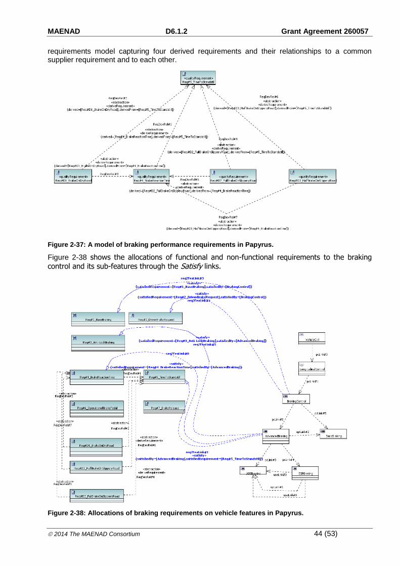
While a feature tree model specifies composition of system functions and their logical dependencies, it often implies the refinement of vehicle level requirements. With EAST-ADL, the derived/derived by relationship of requirements is given by a dedicated requirement relationship:
DeriveRequirement. When such a requirement relationship is declared, a modification of the supplier requirement would have effects on the derived client requirements. Figure 2-37 shows the
MAENAD D6.1.2 Grant Agreement 260057
2014 The MAENAD Consortium 44 (53)
requirements model capturing four derived requirements and their relationships to a common supplier requirement and to each other.
Figure 2-37: A model of braking performance requirements in Papyrus.
Figure 2-38 shows the allocations of functional and non-functional requirements to the braking
control and its sub-features through the Satisfy links.
Figure 2-38: Allocations of braking requirements on vehicle features in Papyrus.

MAENAD D6.1.2 Grant Agreement 260057
2014 The MAENAD Consortium 45 (53)
In EAST-ADL, a satisfy relationship signifies the relationship between a requirement and an architectural element intending to satisfy the requirement. Requirements can also be inherited along with the feature configuration hierarchy. For example, the requirements Req#1_BaseBraking and Req#2_DriverBrakeRequest, shown in Figure 2-38, should also be satisfied by the children of BrakingControl, such as the AdvancedBraking and the BasicBraking.
2.2.3 Analysis Level
As a step towards system realization, the vehicle level features are realised by some interconnected abstract functions at the analysis level, specifying the corresponding input functions, application functions, and output functions for each vehicle level function in an implementation independent way. For the target braking system, the vehicle features of concern are implemented by a set of analysis functions shown in Figure 2-39 and Figure 2-40.
Figure 2-39: Advanced Braking feature and the specification of its functional realizations in Papyrus.
Figure 2-40: Regenerative Braking Control feature and the specification of its functional realizations in Papyrus.
Figure 2-41 shows the specification of functional architecture in EAST-ADL for the braking system (See also D6.1.1 for an overview the functional operation concept).

MAENAD D6.1.2 Grant Agreement 260057
2014 The MAENAD Consortium 46 (53)
Figure 2-41: Functional Analysis Architecture specification of the Regenerative Braking System in Papyrus.
In EAST-ADL, system boundaries are explicitly defined by means of functional devices (FunctionalDevice). Through functional devices, an analysis function interacts with the physical environment. Figure 2-42 shows the connections between functional devices and the physical environment.

MAENAD D6.1.2 Grant Agreement 260057
2014 The MAENAD Consortium 47 (53)
Figure 2-42: Connecting functional analysis functions with environment in Papyrus.
To define the timing requirements and timing design, constructs like TimingConstraint, EventChain and Event are available in EAST-ADL.
Figure 2-43. Synchronization and End-to-end timing from pedal to brake actuators
2.2.4 Design Level
The design level architecture further details the analysis level design by taking the software and hardware resources into consideration. (See also D6.1.1 for an overview the related design concept).

MAENAD D6.1.2 Grant Agreement 260057
2014 The MAENAD Consortium 48 (53)
Functional Design Architecture
Figure 2-44 shows the FunctionalDesignArchitecture. This model is focusing on base braking and does not include energy regeneration functionality.
Figure 2-44. Functional Design Architecture of the Regenerative Braking System in Papyrus.
Figure 2-45 shows the period times of the included functions.
Figure 2-45. Period times of functions
MAENAD D6.1.2 Grant Agreement 260057
2014 The MAENAD Consortium 49 (53)
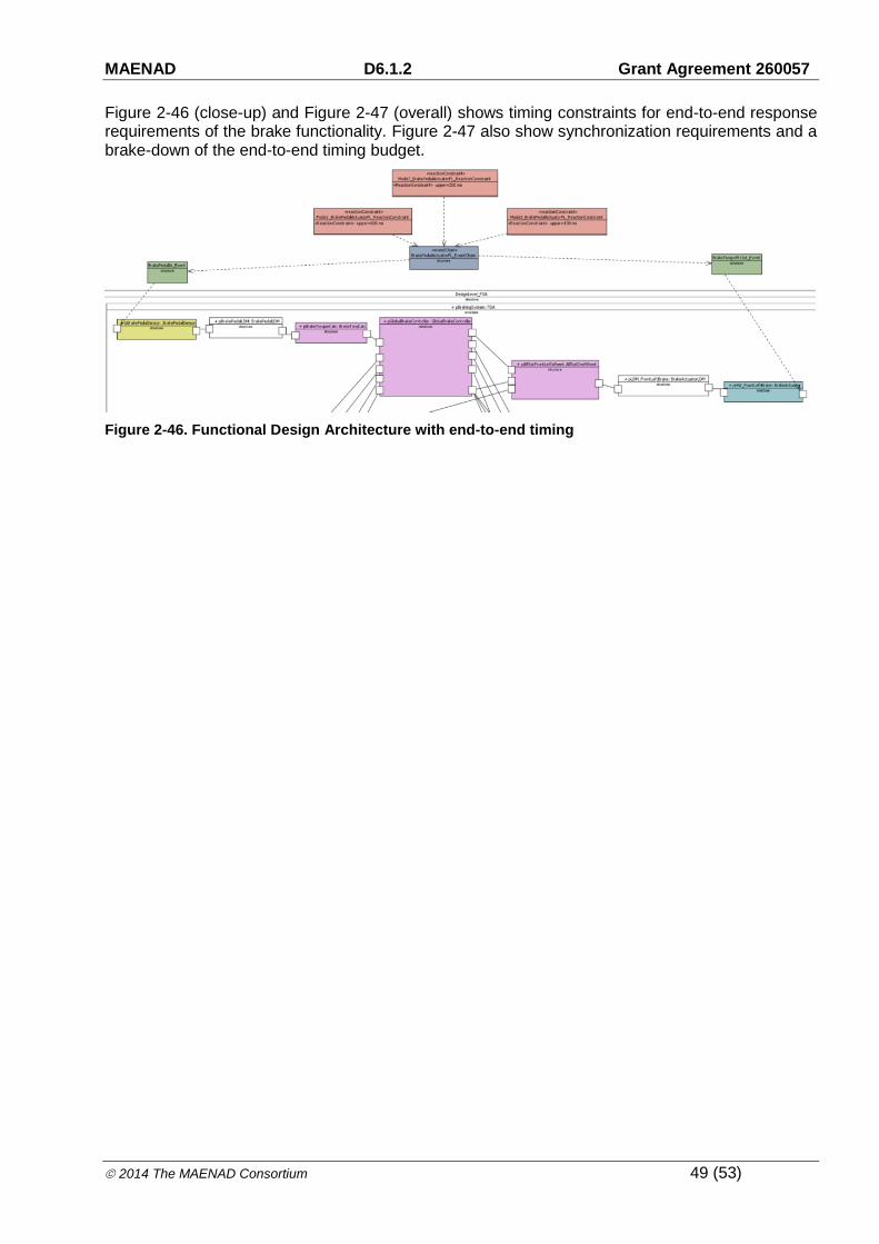
Figure 2-46 (close-up) and Figure 2-47 (overall) shows timing constraints for end-to-end response requirements of the brake functionality. Figure 2-47 also show synchronization requirements and a brake-down of the end-to-end timing budget.
Figure 2-46. Functional Design Architecture with end-to-end timing

MAENAD D6.1.2 Grant Agreement 260057
2014 The MAENAD Consortium 50 (53)
Figure 2-47. Functional Design Architecture with end-to-end timing
Hardware Design Architecture
Figure 2-48 shows an initial HardwareDesignArchitecture.
MAENAD D6.1.2 Grant Agreement 260057
2014 The MAENAD Consortium 51 (53)
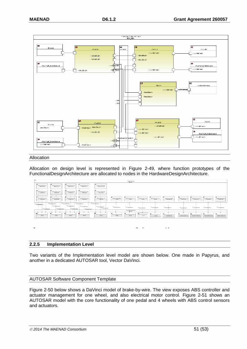
Figure 2-48: Hardware Design Architecture of the Braking System in Papyrus.
Allocation
Allocation on design level is represented in Figure 2-49, where function prototypes of the FunctionalDesignArchitecture are allocated to nodes in the HardwareDesignArchitecture.
Figure 2-49: Function-to-node Allocation in the Braking System in Papyrus.
2.2.5 Implementation Level
Two variants of the Implementation level model are shown below. One made in Papyrus, and another in a dedicated AUTOSAR tool, Vector DaVinci.
AUTOSAR Software Component Template
Figure 2-50 below shows a DaVinci model of brake-by-wire. The view exposes ABS controller and actuator management for one wheel, and also electrical motor control. Figure 2-51 shows an AUTOSAR model with the core functionality of one pedal and 4 wheels with ABS control sensors and actuators.

MAENAD D6.1.2 Grant Agreement 260057
2014 The MAENAD Consortium 52 (53)
WheelSpeedSenso...
ErrorLED
WheelSpinningLED
WheelSpeed_ABS
SpeedSensorPeriodTime
WheelSpeed_OUT
WSS_Debug_Interface
ABS_FL::ABS
BrakeRef_P
WheelSpeed_P
VehicleSpeed_P
DriverRequestedBrakeTorque_P
VehicleModel::VehModel...
RoadCondition VehicleSpeed_P
WheelSpeed_P
GlobalBrakeController::GbBrkCtrl
DriverRequestedBrakeTorque_PBrakeRef_FL
GlobalDebugRece...
EMA_Debug
BPS_PedPos
BA_Debug
WSS_WheelSpeed
BrakeTorqueCalculation::...
DriverRequestedBrakeTorque_P
BrakePedalPosition_P
ElectricalMotorA...
ElectricMotorPWM
EMA_Debug
ExperimentStartButton
MotorOnLED
ErrorLED
RequestInitialPWM
BrakePedalPosition
RequestedPWM
BrakePeda...
PedalPos_InpoutDIO
PedalPressedLED
BrakePedalPosition...
ErrorLED
PedalCalSwitch
PedalPosition_Debug
PedalReading
PedalPosition
ElectricalMotorFeedback:...
Motor_PWMWheelSpeed_P
BrakeActuato...
BrakeTorqueRequest
BrakeTorqueRequeste...
BrakeActuatorPort
ErrorLED
BrakeOnLED
BA_Debug
Figure 2-50. AUTOSAR Software Component Template of the Braking System
Figure 2-51. AUTOSAR Software Component Template of the Braking System

MAENAD D6.1.2 Grant Agreement 260057
2014 The MAENAD Consortium 53 (53)
3 Conclusion
This report provides an overview of the validator models and the related design activities on the selected subsystems performed in MAENAD project. The models evolved during the project activities to address the evolution of the languages or the specific needs for the evaluation of the analysis tools and are currently representing many of the EAST-ADL constructs.