rokkasho reprocessing plant - stanford university
TRANSCRIPT

ROKKASHO REPROCESSING PLANT
JAPAN NUCLEAR FUEL LIMITED 2014. 10
Reprocessing Business Division 4-108 Okitsuke, Oaza Obuchi, Rokkasho-mura, Kamikita-gun, Aomori
TEL 0175-71-2000
JAPAN NUCLEAR FUEL LIMITED
Enrichment Business Division, Radioactive Waste Diposal Business Division 504-22 Noduki, Oaza Obuchi, Rokkasho-mura, Kamikita-gun, Aomori
TEL 0175-72-3311
Aomori General OfficeDaiichi Seimei Building 1-2-15 Houcho, Aomori City, Aomori
TEL 017-773-7171
Tokyo Branch OfficeHibiya Kokusai Building, 2-2-3 Uchsaiwaicho, Chiyoda-ku, Tokyo
TEL 03-6371-5800
URL ht tp ://www. jnfl .co . jp/

Contents
Ⅰ
Ⅱ
Ⅲ
Ⅴ
Ⅳ
Rokkasho Reprocessing Plant is first commercial plant in Japan,adopting the technology
developed on the basis of more than 40years of operation results in both France and United
Kingdom, as well as operating experience gained by Atomic Energy Agency (JAEA).
■ 1
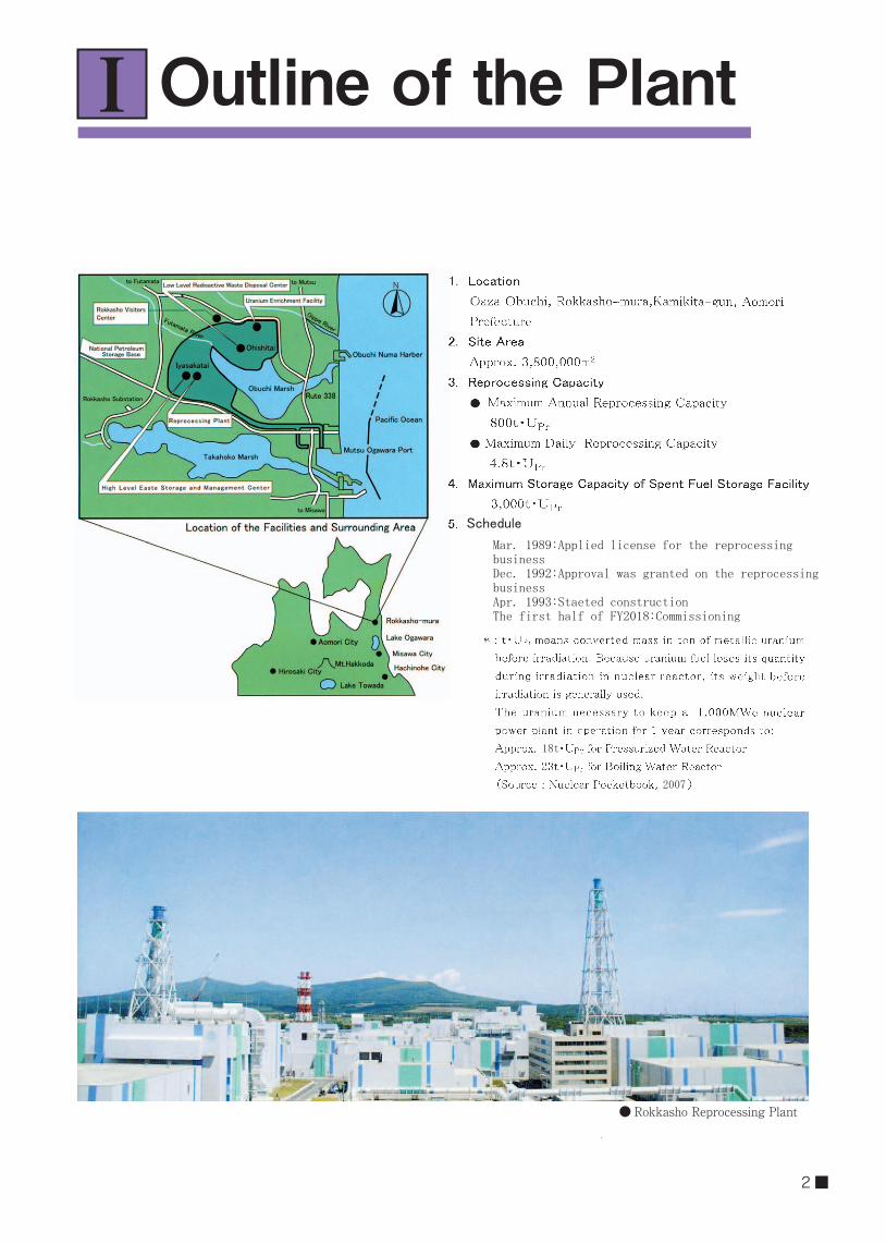
Outline of the PlantⅠ
● Rokkasho Reprocessing Plant
Schedule
Mar. 1989:Applied license for the reprocessing businessDec. 1992:Approval was granted on the reprocessing businessApr. 1993:Staeted constructionThe first half of FY2018:Commissioning
18t
2007
2 ■

Nuclear Fuel Cycle andReprocessing Plants in the World
Uranium MineRefining Plant Conversion Plant
Uranium Hexafluoride
Uranium Enrichment Plant
Enriched Uranium Hexafluoride
Reconversion Plant
Uranium Dioxide
Fabrication Plant
Fuel Assembly
Low-Level Radioactive Waste Disposal Center
Low Level Radioactive Waste
Nuclear Power Plant
Spent Fuel
MOX Fuel
MOX Fuel Fabrication Plant
Recovered Uranium and Plutonium
Uranium Dioxide
Reprocessing Plant
Vitrified Waste Storage Center
High Level Radioactive Waste
Underground Storage Facility
Recycle Fuel Stock Center
Recovered Uranium
Spent Fuel
Nuclear Fuel Cycle
Ⅱ
3 5
3 5
■ 3

Uranium Ore Uranium Fuel(Before Irradiation)
Uranium Fuel(After Irradiation) MOX Fuel
U-235approx. 0.7%
U-238
U-2353~5%
U-235approx. 1%
Plutoniumapprox. 1%
Fission Productsapprox. 3%
U-238approx. 95%
Plutonium4~9%
U-238 U-238,etc.
The Composition of Uranium Fuel for Light Water Reacter and MOX Fuel
4 ■

Reprocessing PlantⅢ
Process Outline
Cask Cask
Spent Fuel
Cladding Tubes,etc.
Separationof FP
Separation ofUranium andPlutonium
Pur if icat ionof
Uran ium
Purif icationof
Plutonium
To be Placed in Containers and Storedin the Storage Facility
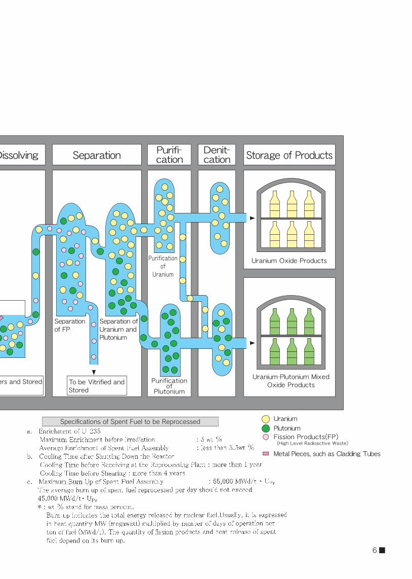
Receiving and Storage Shearing and Dissolving Separation Storage of ProductsPurifi-cation
Denit-cation
To be Vitrified andStored
Uranium Oxide Products
Uranium-Plutonium MixedOxide Products
Uranium
Metal Pieces, such as Cladding Tubes
PlutoniumFission Products(FP)(High Level Radioactive Waste)
■ 5
Cask Cask
Spent Fuel
Cladding Tubes,etc.
Separationof FP
Separation ofUranium andPlutonium
Pur if icat ionof
Uran ium
Purif icationof
Plutonium
To be Placed in Containers and Storedin the Storage Facility
Receiving and Storage Shearing and Dissolving Separation Storage of ProductsPurifi-cation
Denit-cation
To be Vitrified andStored
Uranium Oxide Products
Uranium-Plutonium MixedOxide Products
Uranium
Metal Pieces, such as Cladding Tubes
PlutoniumFission Products(FP)(High Level Radioactive Waste)
Specifications of Spent Fuel to be Reprocessed
6 ■
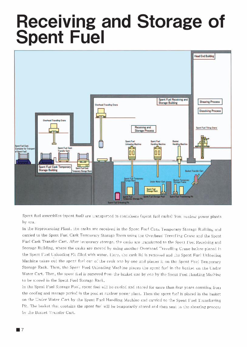
Receiving and Storage ofSpent Fuel
■ 7
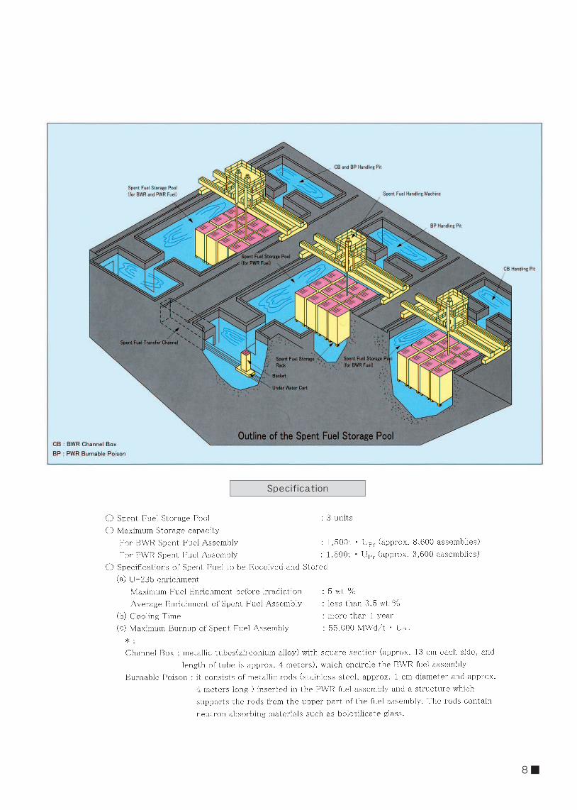
Spec if icat ion
8 ■
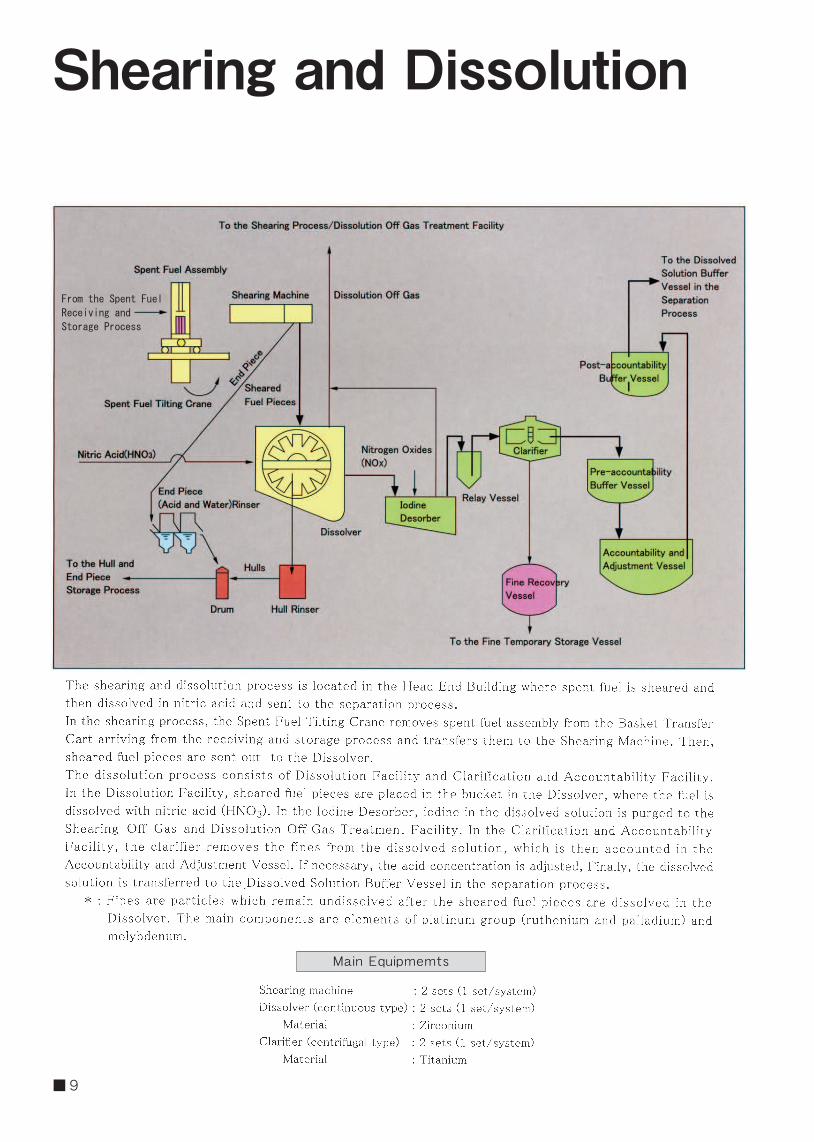
Shearing and Dissolution
Main Equ ipmemts
From the Spent Fuel
Receiving and
Storage Process
■ 9

Shearing-Blade Holder
Lid
Body
End Piece Outlet
(To End Piece Chute)
Sheared Fuel Pieces Outlet(To Sheared Fuel Pieces Chute)
Hopper
Magazine
Spent Fuel Assembly
Fuel Inlet
Fuel Feeder
uxiliary Fuei-HolderDrive Cylinder
Main Fuel-HolderDrive Cylinder
Shearing-Blade Drive Cylinder
Outline of Shearing Machine
10 ■
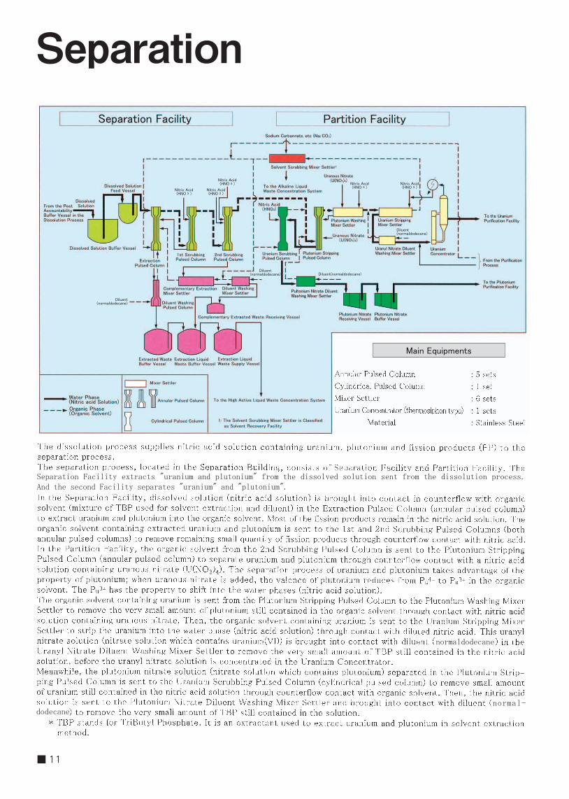
Separation
Main Equipments
Separation Facility extracts "uranium and plutonium" from the dissolved solution sent from the dissolution process. And the second Facility separates "uranium" and "plutonium".
normaldodecane
normal-dodecane
Nitric Acid(HNO 3 )
Nitric Acid(HNO 3 )
Nitric Acid(HNO 3 ) Nitric Acid
(HNO 3 )Nitric Acid(HNO 3 )
Diluent(normaldodecane)
Diluent(normaldodecane)Diluent
(normaldodecane)
Diluent(normaldodecane)
■ 11
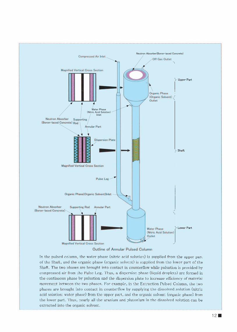
Neutron Absorber(Boron-iaced Concrete)
Water Phase(Nitric Acid Solution)
Inlet
12 ■
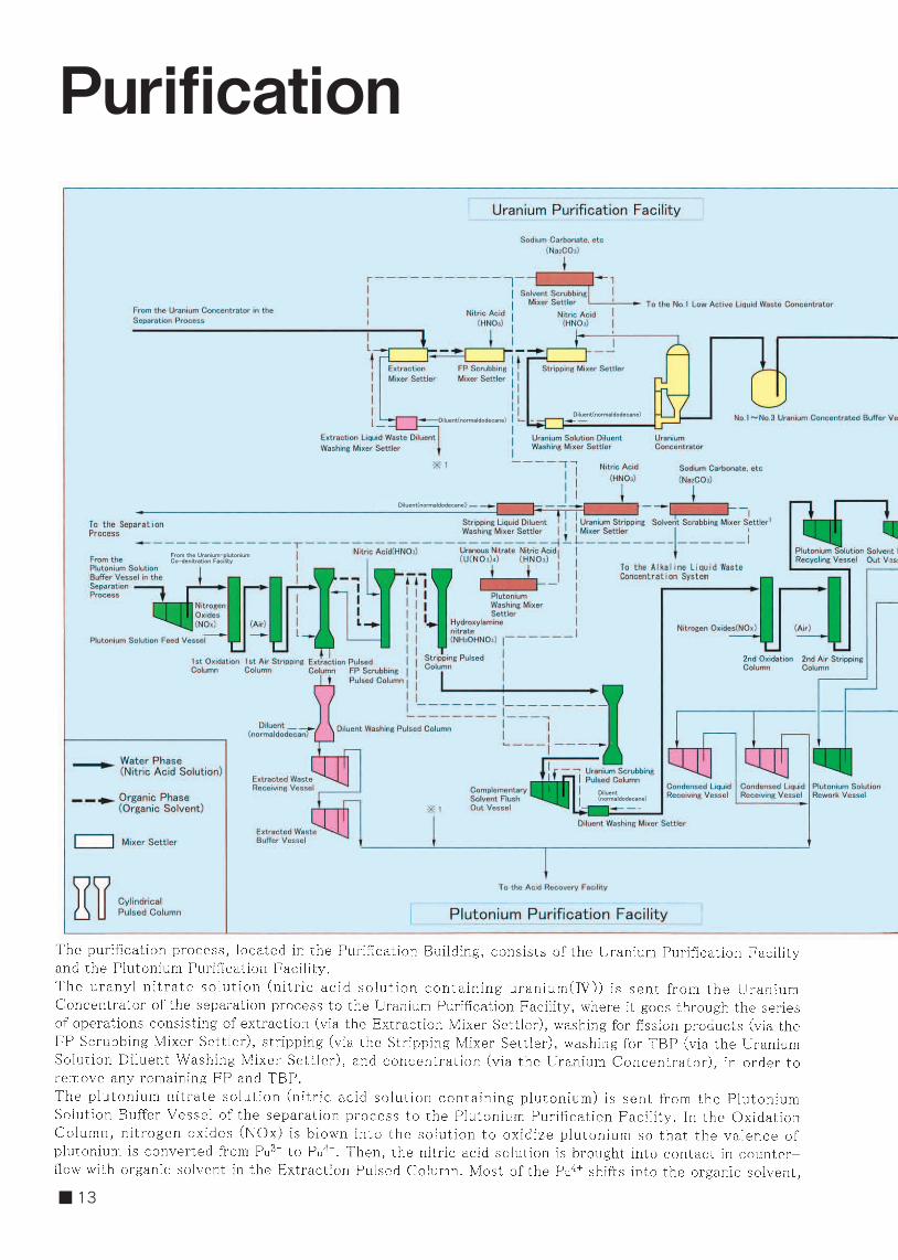
Purification
Diluent(normaldodecane)Diluent(normaldodecane)
From the Uranium-plutoniumCo-denitration Facility
Diluent(normaldodecane)
Diluent(normaldodecane)
■ 13

Main Equipments
As a result, impurities in the organic solvent containing plutonium will be rebuced.
normaldodecane
14 ■

Denitration andProduct Storage
主 な 仕 様
Seal Vessel
■ 15

* :Fluidized-bed is a state in which particles behave as liquid, when small particles filled in a container are blown with gas from the bottom (UO3 particles in the case of Uranium Denitration Facility).
For microwave heating, the same frequency is used as microwave oven for home use.
Microwave Generator
Microwave Leader
Body
MixedSolution
Turn-Table
DenitrationDish
In the Denitrator that is installed in the Uranium-
plutonium Co-denitration Facility, the mixed solution
of the plutonium nitrate solution and the uranyl nitrate
solution is surprised into the Denitration Dish, then
concentrated and denitrated by microwave.
Outline of the DenitratorIn the Denitration Column that is installed in the
Uranium Denitration Facility, air is supplied from the
lower part of the column to form the fluidized bed of
the UO3 powder. The uranyl nitrate solution is sprayed
into this fluidized bed from spray nozzles with air, and
electric heaters thermally decompose the solution at
approximately 300℃ .
Outline of the Denitration Column
Off Gas Outlet Blowback Air Inlet
Candle Filter
Body
Seed Powder Inlet
UO3 Powder Outlet
Internal Heater Tubes
Underflow Nozzle
Electric Heater
Spray Nozzle
Molten Salt Outlet
Molten Salt Inlet
Fluidizing Ari Inlet
16 ■
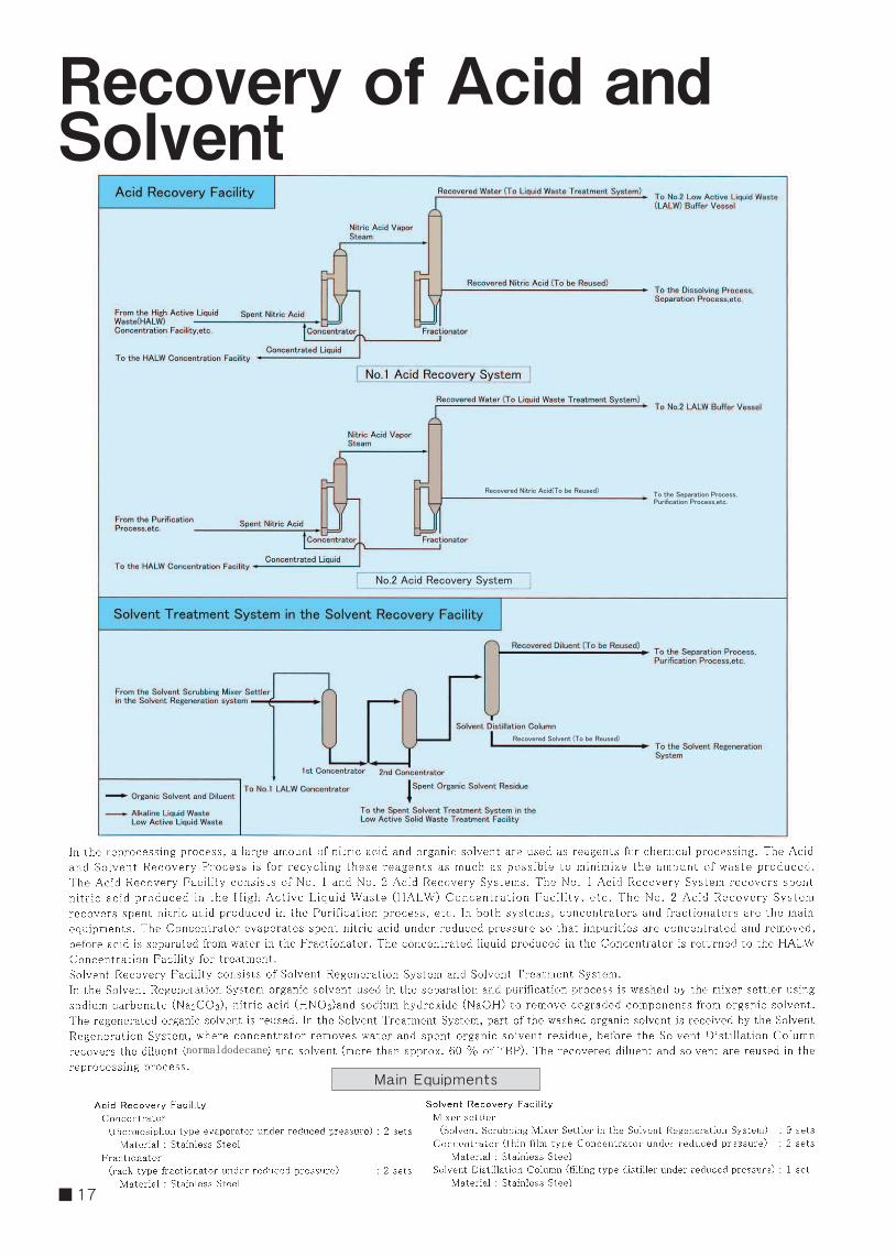
Recovery of Acid andSolvent
Main Equ ipments
normaldodecane
Recovered Nitric Acid(To be Reused)To the Separation Process,Purification Process,etc.
Recovered Solvent (To be Reused)
No.2 Acid Recovery System
■ 17

Gaseous Waste
From the Shearing Machine,Dissolver,lodine Desorder,etc.
From the PlutoniumConcentraton Feed Vessel, etc.in the Purification Process
1st OxidationColumu,etc. in the Purification Process
NOxScrubbingColumn
To the Main StackHeater,Iodine Filter,etc.
Main Equ ipmentsShearing Off Gas and Dissolution Off Gas Treatment FacilityHEPA Filter : 6 sets(composed of 2 stages) Particle elimination efficiency : more than 99.9%(0.3μmDOP particle)/stageIodine Filter : 12 sets(composed of 2 stages) Iodine elimination efficiency : more than 99.6%
Vessel Off Gas Treatment Facility HEPA Filter Particle elimination efficiency : more than 99.9%(0.3μmDOP particle)/stageIodine Filter Iodine elimination efficiency : more than 90%
HALW Vitrification Off Gas Treatment FacilityHEPA Filter Column type : 4 sets(composed of 2 stages) Box type : 2 sets Particle elimination efficiency : more than 99.9%(0.3μmDOP particle)/stageIodine Filter : 2 sets Iodine elimination efficiency : more than 90% 18 ■
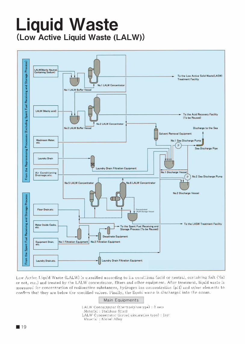
Ma in Equ ipments
Liquid Waste(Low Active Liquid Waste (LALW))
ConcentratedLALW Storage Vessel
■ 19
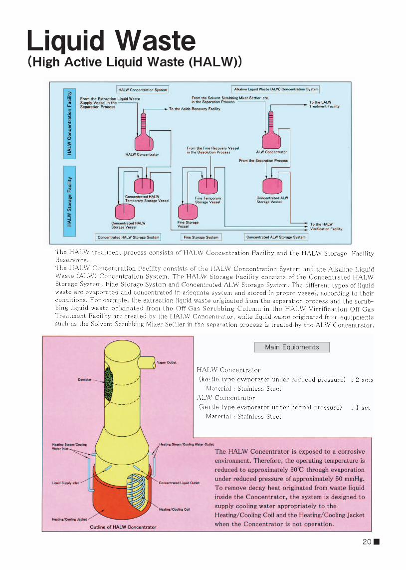
Liquid Waste(High Active Liquid Waste (HALW))
Main Equipments
20 ■

Solid Waste
■ 21

Molten Glass
Electrode
Casing
Off Gas outletGlass Material inlet
HALW inlet
Firebrick
Air NozzleFlow down NozzleFlow down Glass
Heating Coil
Off Gas outletCombination System
Canister
PaletteSolidified Glass
Vitrification Cell TransferCart
Weidht Monitor
Outline of Vitrification Melter
In the Virtification Melter, electric
current passes directly through the
glass by using electrode installed
in the furnace, and it melts by the
generating heat of Joule. The molten
glass in a Vitrification Melter is
poured into the canister by heating the
flow-down nozzle located at the lower
part of casing.
22 ■

Central Control Room
Analysis Facility
■ 23

Safety MeasuresⅣ
trays.
Schem of Multiple Protection against Leakage
24 ■

■ 25

Center For Research &Development
Ⅴ
26 ■
ROKKASHO REPROCESSING PLANT
JAPAN NUCLEAR FUEL LIMITED2014. 10
Reprocessing Business Division 4-108 Okitsuke, Oaza Obuchi, Rokkasho-mura, Kamikita-gun, Aomori
TEL 0175-71-2000
JAPAN NUCLEAR FUEL LIMITED
Enrichment Business Division, Radioactive Waste Diposal Business Division 504-22 Noduki, Oaza Obuchi, Rokkasho-mura, Kamikita-gun, Aomori
TEL 0175-72-3311
Aomori General OfficeDaiichi Seimei Building 1-2-15 Houcho, Aomori City, Aomori
TEL 017-773-7171
Tokyo Branch OfficeHibiya Kokusai Building, 2-2-3 Uchsaiwaicho, Chiyoda-ku, Tokyo
TEL 03-6371-5800
URL ht tp ://www. jnfl .co . jp/