schinko blend en
TRANSCRIPT
7/29/2019 Schinko Blend En
http://slidepdf.com/reader/full/schinko-blend-en 1/5
Texture blending using weight maps in Softimage XSIby Christoph Schinko
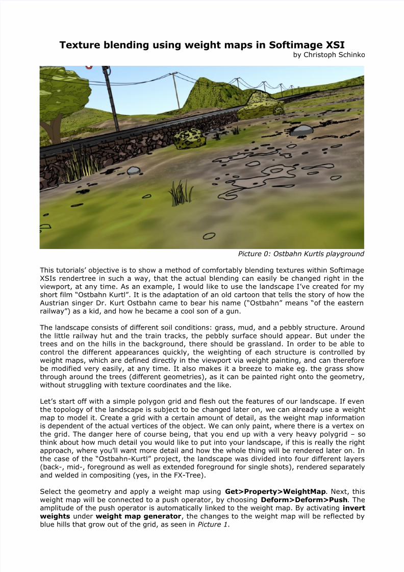
Picture 0: Ostbahn Kurtls playground
This tutorials’ objective is to show a method of comfortably blending textures within SoftimageXSIs rendertree in such a way, that the actual blending can easily be changed right in theviewport, at any time. As an example, I would like to use the landscape I’ve created for myshort film “Ostbahn Kurtl”. It is the adaptation of an old cartoon that tells the story of how the
Austrian singer Dr. Kurt Ostbahn came to bear his name (“Ostbahn” means “of the easternrailway”) as a kid, and how he became a cool son of a gun.
The landscape consists of different soil conditions: grass, mud, and a pebbly structure. Around
the little railway hut and the train tracks, the pebbly surface should appear. But under thetrees and on the hills in the background, there should be grassland. In order to be able to
control the different appearances quickly, the weighting of each structure is controlled byweight maps, which are defined directly in the viewport via weight painting, and can thereforebe modified very easily, at any time. It also makes it a breeze to make eg. the grass showthrough around the trees (different geometries), as it can be painted right onto the geometry,without struggling with texture coordinates and the like.
Let’s start off with a simple polygon grid and flesh out the features of our landscape. If eventhe topology of the landscape is subject to be changed later on, we can already use a weight
map to model it. Create a grid with a certain amount of detail, as the weight map informationis dependent of the actual vertices of the object. We can only paint, where there is a vertex on
the grid. The danger here of course being, that you end up with a very heavy polygrid – sothink about how much detail you would like to put into your landscape, if this is really the rightapproach, where you’ll want more detail and how the whole thing will be rendered later on. Inthe case of the “Ostbahn-Kurtl” project, the landscape was divided into four different layers(back-, mid-, foreground as well as extended foreground for single shots), rendered separatelyand welded in compositing (yes, in the FX-Tree).
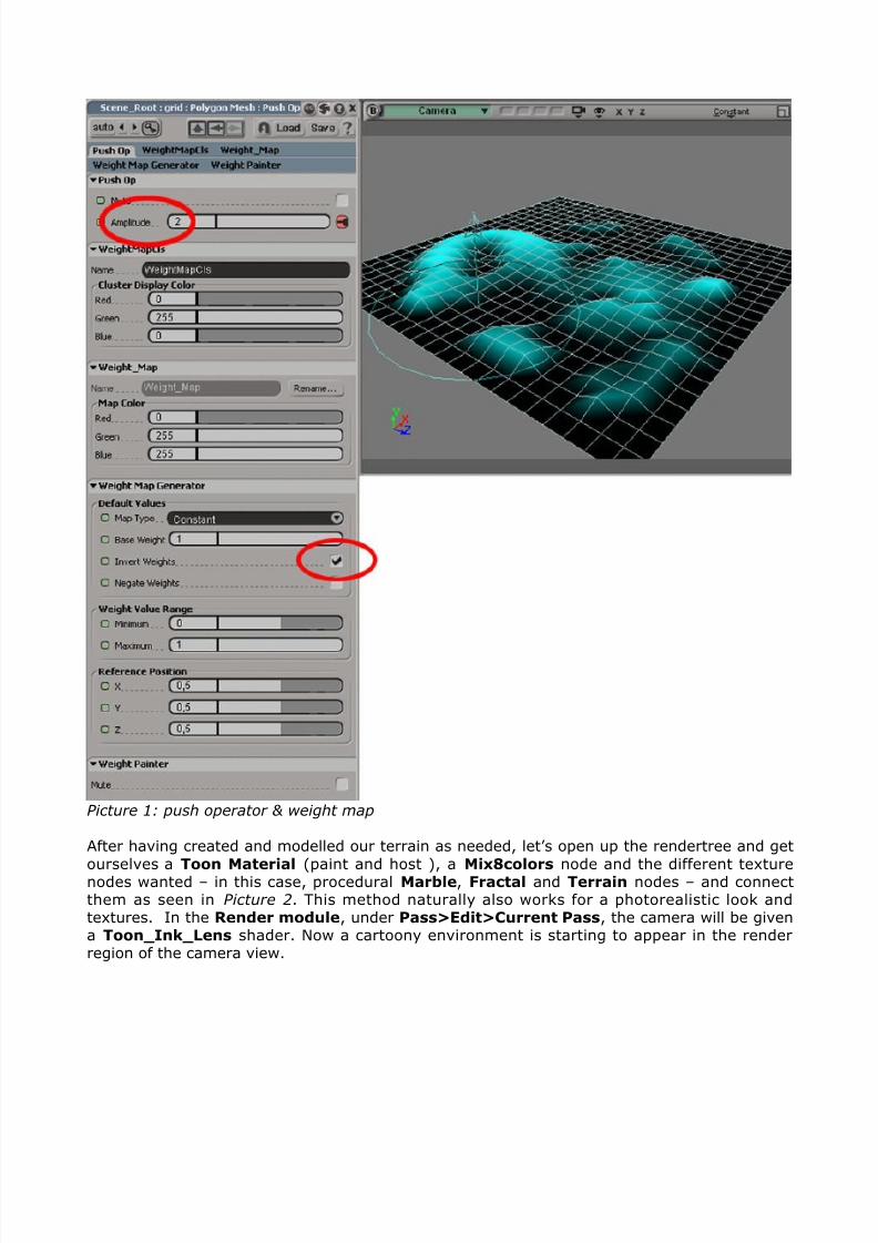
Select the geometry and apply a weight map using Get>Property>WeightMap. Next, this
weight map will be connected to a push operator, by choosing Deform>Deform>Push. Theamplitude of the push operator is automatically linked to the weight map. By activating invert
weights under weight map generator, the changes to the weight map will be reflected byblue hills that grow out of the grid, as seen in Picture 1.
7/29/2019 Schinko Blend En
http://slidepdf.com/reader/full/schinko-blend-en 2/5
Picture 1: push operator & weight map
After having created and modelled our terrain as needed, let’s open up the rendertree and get
ourselves a Toon Material (paint and host ), a Mix8colors node and the different texturenodes wanted – in this case, procedural Marble, Fractal and Terrain nodes – and connectthem as seen in Picture 2. This method naturally also works for a photorealistic look andtextures. In the Render module, under Pass>Edit>Current Pass, the camera will be givena Toon_Ink_Lens shader. Now a cartoony environment is starting to appear in the renderregion of the camera view.

7/29/2019 Schinko Blend En
http://slidepdf.com/reader/full/schinko-blend-en 3/5
Picture 2: rendertree 1
Now to define the look of each texture node separately, without the typical ink lines at first,
those will be added later. Still, the geometry itself will cause ink lines, if caused by itstopology, but for now the texture nodes won’t create additional inking according to its
structure and appearance.
Hint 1: To comfortably adjust one node after another, it’s best to switch off all other layers inthe Mix8colors node (rather than disconnecting them) and set the weighting of the layer tobe worked on to 1. That way, you see exactly what’s happening, and you won’t accidentallyloose your other texture nodes when hitting “update” in the rendertree or when selectinganother object in the viewport.
Picture 3: switching off layers
After defining the different ground structures, it is time to create the weight maps and painttheir contributions to the landscape as a whole. In order to do that, get a Map
Lookups>Color node and connect it to the weighting input of the second(!) layer of theMix8Colors node (the first, or base layer will be 100% visible along the whole geometry, theothers will be blended in over top of that. Therefore, the first layer doesn’t need to becontrolled by a weight map).In the PPG (property page) of this node, a weight map is created by clicking New>WeightMap. And right away the painting of the weight map can begin by activating the paint tool inthe viewport by pressing “w” (make sure that “weight maps” is activated inside the visibility

7/29/2019 Schinko Blend En
http://slidepdf.com/reader/full/schinko-blend-en 4/5
options -the “eye” icon- of that viewport).
Picture 4: rendertree 2
Do the same for the third texture layer – you’ll get another weight map, and can paint on the
contribution of the third texture node to the landscape.
Hint 2: Select the grid and hit Explore>PolyMesh>Clusters>WeightMapCls in the MCP(main control panel) to easily select and therefore switch between your weight maps.
Picture 5: Explore weight maps
To get closer towards the final look, each texture should create ink lines aswell, depending on

7/29/2019 Schinko Blend En
http://slidepdf.com/reader/full/schinko-blend-en 5/5
their structure and appearance. This can be done by connecting a Math>Scalar Basic nodewith the host_unblend_group of the toon shader. The Scalar basic node is now fed with thesame tree that causes the texturing (everything including the Mix8Color node). But, as we’llneed different settings for each texture node (to have control of the inking independently of the colouring), let’s duplicate the tree by middle-clicking on the Mix8Color Node, and hittingCtrl+C and Ctrl+V to copy and paste the selected tree. Feed this new tree into Scalar BasicNode>Input 1. You can re-connect the old MapLookupColor Nodes and get rid of the new
ones, just to have less nodes in the tree.
The adjustment of the ink lines for each textures needs a bit of tweaking. Color-values just
above 1 seemed to work best for the “Ostbahn” project. The Vein 2 value of the marble texturewas set to 1,05, the Color 1 value of the fractal node to 1,2, and in the terrain node, the colorvalues were increased and the boundaries changed.This way, the ink contribution of each ground structure can be adjusted quite easily, and you’llstill have control over the colouring of each part.
Hint 3: The “node preview” function of the rendertree used to be extremely useful.Unfortunately, it died, but can be revived like this: Create a new key map under
File>Keyboard mapping. Under the “Render Tree” group, the lost command “Node Preview
(Obsolete)” can be found, and is easily dragged and dropped onto “P”, where it belongs.
Hopefully, this tutorial helps you to understand weight maps and the rendertree a little bitbetter. Enjoy playing around!
Christoph Schinko, 2003
Picture 6: It’s alive!