scope of accreditation to iso/iec 17025:2005 … · dl output accuracy (0.5 to 3) ghz modulation dl...
TRANSCRIPT
(A2LA Cert. No. 3128.01) Revised 10/04/2017 Page 1 of 28
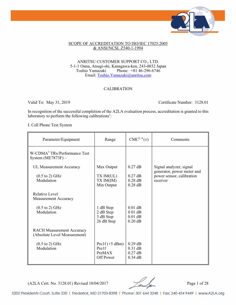
SCOPE OF ACCREDITATION TO ISO/IEC 17025:2005 & ANSI/NCSL Z540-1-1994
ANRITSU CUSTOMER SUPPORT CO., LTD. 5-1-1 Onna, Atsugi-shi, Kanagawa-ken, 243-0032 Japan
Toshio Yamazaki Phone: +81 46-296-6746 Email: [email protected]
CALIBRATION
Valid To: May 31, 2019 Certificate Number: 3128.01 In recognition of the successful completion of the A2LA evaluation process, accreditation is granted to this laboratory to perform the following calibrations1: I. Cell Phone Test System
Parameter/Equipment
Range CMC2, 4 (±)
Comments
W-CDMA3 TRx/Performance Test System (ME7873F) –
UL Measurement Accuracy
(0.5 to 2) GHz Modulation
Relative Level Measurement Accuracy
(0.5 to 2) GHz Modulation
RACH Measurement Accuracy (Absolute Level Measurement)
(0.5 to 2) GHz Modulation
Max Output TX IM(UL) TX IM(IM) Min Output 1 dB Step 2 dB Step 3 dB Step 26 dB Step Pre1f (+5 dBm) Pre1f PreMAX Off Power
0.27 dB 0.27 dB 0.28 dB 0.28 dB 0.01 dB 0 01 dB 0.01 dB 0.20 dB 0.29 dB 0.31 dB 0.27 dB 0.34 dB
Signal analyzer, signal generator, power meter and power sensor, calibration receiver
(A2LA Cert. No. 3128.01) Revised 10/04/2017 Page 2 of 28
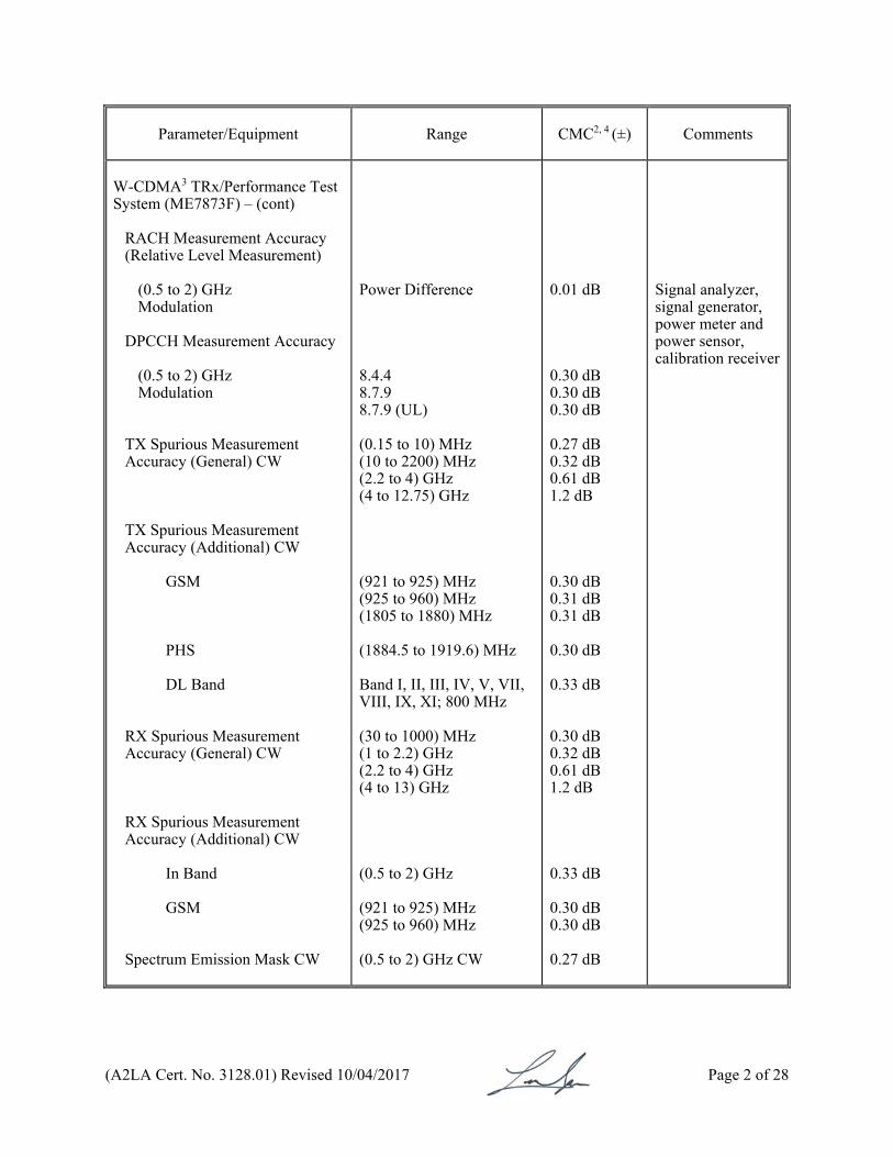
Parameter/Equipment
Range CMC2, 4 (±)
Comments
W-CDMA3 TRx/Performance Test System (ME7873F) – (cont)
RACH Measurement Accuracy (Relative Level Measurement)
(0.5 to 2) GHz Modulation
DPCCH Measurement Accuracy
(0.5 to 2) GHz Modulation
TX Spurious Measurement Accuracy (General) CW TX Spurious Measurement Accuracy (Additional) CW GSM PHS DL Band RX Spurious Measurement Accuracy (General) CW RX Spurious Measurement Accuracy (Additional) CW
In Band GSM
Spectrum Emission Mask CW
Power Difference 8.4.4 8.7.9 8.7.9 (UL) (0.15 to 10) MHz (10 to 2200) MHz (2.2 to 4) GHz (4 to 12.75) GHz (921 to 925) MHz (925 to 960) MHz (1805 to 1880) MHz (1884.5 to 1919.6) MHz Band I, II, III, IV, V, VII, VIII, IX, XI; 800 MHz (30 to 1000) MHz (1 to 2.2) GHz (2.2 to 4) GHz (4 to 13) GHz (0.5 to 2) GHz (921 to 925) MHz (925 to 960) MHz (0.5 to 2) GHz CW
0.01 dB 0.30 dB 0.30 dB 0.30 dB 0.27 dB 0.32 dB 0.61 dB 1.2 dB 0.30 dB 0.31 dB 0.31 dB 0.30 dB 0.33 dB 0.30 dB 0.32 dB 0.61 dB 1.2 dB 0.33 dB 0.30 dB 0.30 dB 0.27 dB
Signal analyzer, signal generator, power meter and power sensor, calibration receiver
(A2LA Cert. No. 3128.01) Revised 10/04/2017 Page 3 of 28
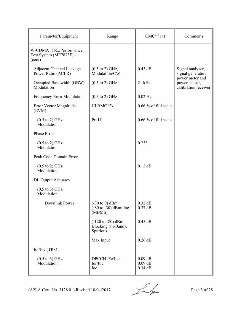
Parameter/Equipment
Range CMC2, 4 (±)
Comments
W-CDMA3 TRx/Performance Test System (ME7873F) – (cont)
Adjacent Channel Leakage Power Ratio (ACLR) Occupied Bandwidth (OBW) Modulation Frequency Error Modulation Error Vector Magnitude (EVM)
(0.5 to 2) GHz Modulation
Phase Error
(0.5 to 2) GHz Modulation
Peak Code Domain Error
(0.5 to 2) GHz Modulation
DL Output Accuracy
(0.5 to 3) GHz Modulation Downlink Power
Ior/Ioc (TRx)
(0.5 to 3) GHz Modulation
(0.5 to 2) GHz, Modulation/CW (0.5 to 2) GHz (0.5 to 2) GHz ULRMC12k Pre1f (-30 to 0) dBm (-80 to -30) dBm; Ioc (MBMS) (-120 to -80) dBm Blocking (In-Band), Spurious Max Input DPCCH_Ec/Ioc Ior/Ioc Ioc
0.43 dB 21 kHz 0.02 Hz 0.66 % of full scale 0.66 % of full scale 0.23° 0.12 dB 0.32 dB 0.37 dB 0.45 dB 0.26 dB 0.09 dB 0.09 dB 0.34 dB
Signal analyzer, signal generator, power meter and power sensor, calibration receiver
(A2LA Cert. No. 3128.01) Revised 10/04/2017 Page 4 of 28
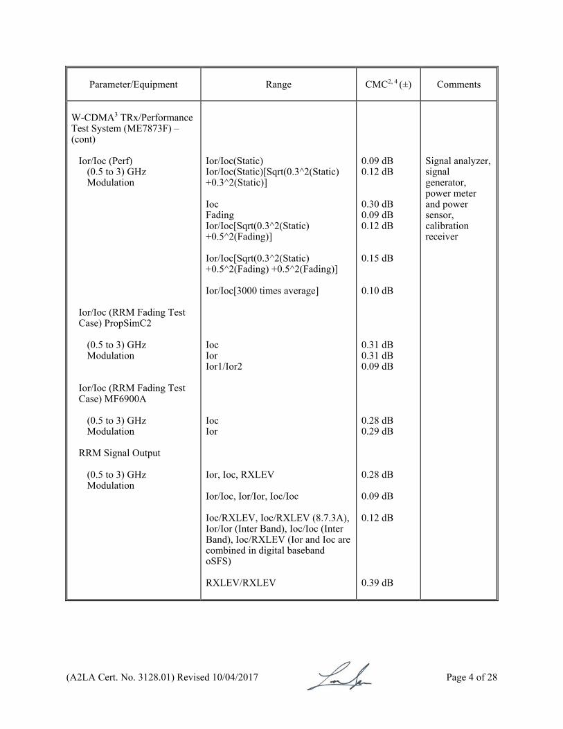
Parameter/Equipment
Range CMC2, 4 (±) Comments
W-CDMA3 TRx/Performance Test System (ME7873F) – (cont)
Ior/Ioc (Perf) (0.5 to 3) GHz Modulation
Ior/Ioc (RRM Fading Test Case) PropSimC2
(0.5 to 3) GHz Modulation
Ior/Ioc (RRM Fading Test Case) MF6900A
(0.5 to 3) GHz Modulation
RRM Signal Output
(0.5 to 3) GHz Modulation
Ior/Ioc(Static) Ior/Ioc(Static)[Sqrt(0.3^2(Static) +0.3^2(Static)] Ioc Fading Ior/Ioc[Sqrt(0.3^2(Static) +0.5^2(Fading)] Ior/Ioc[Sqrt(0.3^2(Static) +0.5^2(Fading) +0.5^2(Fading)] Ior/Ioc[3000 times average] Ioc Ior Ior1/Ior2 Ioc Ior Ior, Ioc, RXLEV Ior/Ioc, Ior/Ior, Ioc/Ioc Ioc/RXLEV, Ioc/RXLEV (8.7.3A), Ior/Ior (Inter Band), Ioc/Ioc (Inter Band), Ioc/RXLEV (Ior and Ioc are combined in digital baseband oSFS) RXLEV/RXLEV
0.09 dB 0.12 dB 0.30 dB 0.09 dB 0.12 dB 0.15 dB 0.10 dB 0.31 dB 0.31 dB 0.09 dB 0.28 dB 0.29 dB 0.28 dB 0.09 dB 0.12 dB 0.39 dB
Signal analyzer, signal generator, power meter and power sensor, calibration receiver

(A2LA Cert. No. 3128.01) Revised 10/04/2017 Page 5 of 28
Parameter/Equipment
Range CMC2, 4 (±)
Comments
W-CDMA3 TRx/Performance Test System (ME7873F) – (cont)
CW Interference Modulation Interference
(0.5 to 3) GHz Modulation
GSM Interference
(0.5 to 3) GHz Modulation
Blocking: (10 to 3000) Hz Blocking: (3 to 8) GHz Blocking: (8 to 13) GHz RX IM TX IM SG2->CpDSG->Isolator->Antenna SG2->Isolator->Antenna Intermodulation Characteristics Blocking Characteristics (Narrow Band) Intermodulation Characteristics (Narrow Band)
0.26 dB 0.54 dB 1.1 dB 0.26 dB 0.26 dB 0.29 dB 0.29 dB 0.26 dB 0.29 dB 0.26 dB
Signal analyzer, signal generator, power meter and power sensor, calibration receiver
(A2LA Cert. No. 3128.01) Revised 10/04/2017 Page 6 of 28
Parameter/Equipment
Range CMC2, 4 (±)
Comments
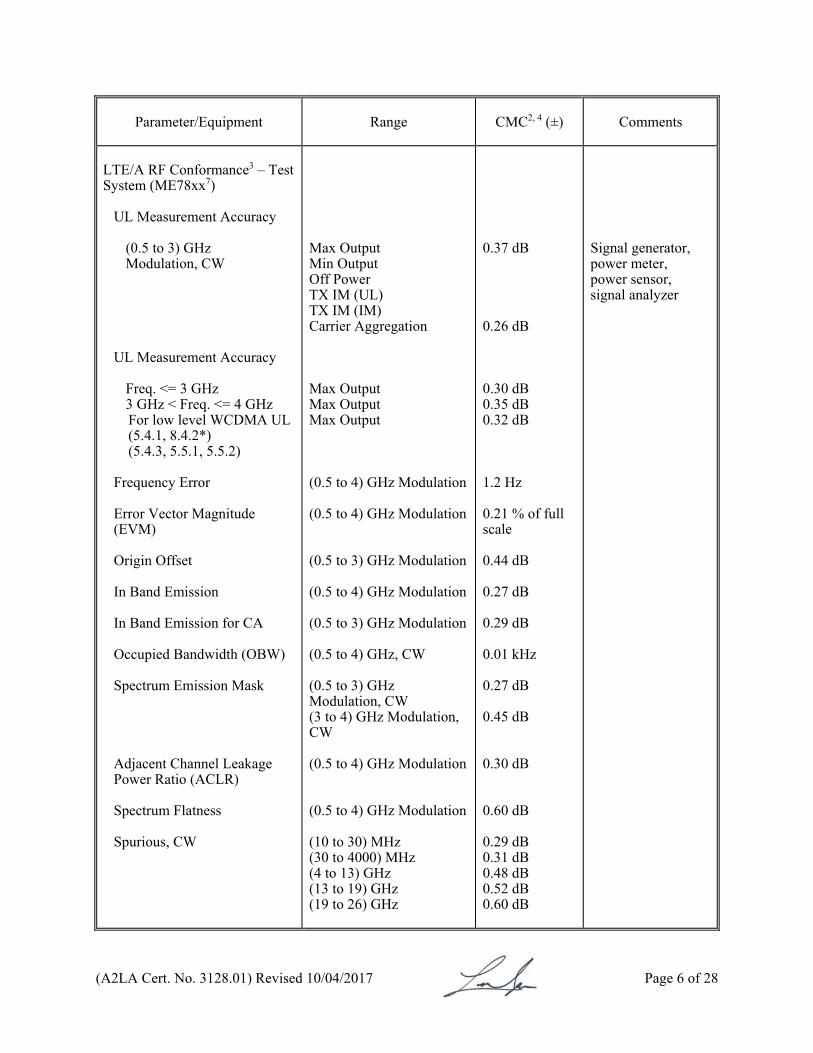
LTE/A RF Conformance3 – Test System (ME78xx7)
UL Measurement Accuracy
(0.5 to 3) GHz Modulation, CW
UL Measurement Accuracy
Freq. <= 3 GHz 3 GHz < Freq. <= 4 GHz For low level WCDMA UL (5.4.1, 8.4.2*) (5.4.3, 5.5.1, 5.5.2)
Frequency Error Error Vector Magnitude (EVM) Origin Offset In Band Emission In Band Emission for CA Occupied Bandwidth (OBW) Spectrum Emission Mask Adjacent Channel Leakage Power Ratio (ACLR) Spectrum Flatness Spurious, CW
Max Output Min Output Off Power TX IM (UL) TX IM (IM) Carrier Aggregation Max Output Max Output Max Output (0.5 to 4) GHz Modulation (0.5 to 4) GHz Modulation (0.5 to 3) GHz Modulation (0.5 to 4) GHz Modulation (0.5 to 3) GHz Modulation (0.5 to 4) GHz, CW (0.5 to 3) GHz Modulation, CW (3 to 4) GHz Modulation, CW (0.5 to 4) GHz Modulation (0.5 to 4) GHz Modulation (10 to 30) MHz (30 to 4000) MHz (4 to 13) GHz (13 to 19) GHz (19 to 26) GHz
0.37 dB 0.26 dB 0.30 dB 0.35 dB 0.32 dB 1.2 Hz 0.21 % of full scale 0.44 dB 0.27 dB 0.29 dB 0.01 kHz 0.27 dB 0.45 dB 0.30 dB 0.60 dB 0.29 dB 0.31 dB 0.48 dB 0.52 dB 0.60 dB
Signal generator, power meter, power sensor, signal analyzer
(A2LA Cert. No. 3128.01) Revised 10/04/2017 Page 7 of 28
Parameter/Equipment
Range CMC2, 4 (±) Comments
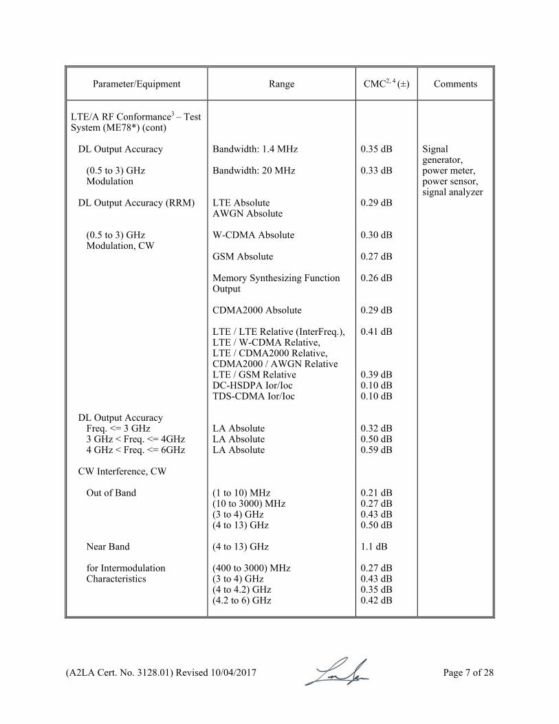
LTE/A RF Conformance3 – Test System (ME78*) (cont)
DL Output Accuracy
(0.5 to 3) GHz Modulation
DL Output Accuracy (RRM)
(0.5 to 3) GHz Modulation, CW
DL Output Accuracy Freq. <= 3 GHz 3 GHz < Freq. <= 4GHz 4 GHz < Freq. <= 6GHz
CW Interference, CW
Out of Band Near Band for Intermodulation Characteristics
Bandwidth: 1.4 MHz Bandwidth: 20 MHz LTE Absolute AWGN Absolute W-CDMA Absolute GSM Absolute Memory Synthesizing Function Output CDMA2000 Absolute LTE / LTE Relative (InterFreq.), LTE / W-CDMA Relative, LTE / CDMA2000 Relative, CDMA2000 / AWGN Relative LTE / GSM Relative DC-HSDPA Ior/Ioc TDS-CDMA Ior/Ioc LA Absolute LA Absolute LA Absolute (1 to 10) MHz (10 to 3000) MHz (3 to 4) GHz (4 to 13) GHz (4 to 13) GHz (400 to 3000) MHz (3 to 4) GHz (4 to 4.2) GHz (4.2 to 6) GHz
0.35 dB 0.33 dB 0.29 dB 0.30 dB 0.27 dB 0.26 dB 0.29 dB 0.41 dB 0.39 dB 0.10 dB 0.10 dB 0.32 dB 0.50 dB 0.59 dB 0.21 dB 0.27 dB 0.43 dB 0.50 dB 1.1 dB 0.27 dB 0.43 dB 0.35 dB 0.42 dB
Signal generator, power meter, power sensor, signal analyzer
(A2LA Cert. No. 3128.01) Revised 10/04/2017 Page 8 of 28
Parameter/Equipment
Range CMC2, 4 (±) Comments
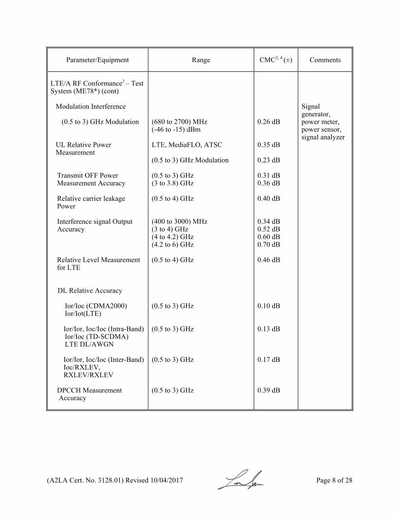
LTE/A RF Conformance3 – Test System (ME78*) (cont)
Modulation Interference (0.5 to 3) GHz Modulation
UL Relative Power Measurement
Transmit OFF Power Measurement Accuracy
Relative carrier leakage Power
Interference signal Output Accuracy
Relative Level Measurement for LTE
DL Relative Accuracy
Ior/Ioc (CDMA2000) Ior/Iot(LTE)
Ior/Ior, Ioc/Ioc (Intra-Band) Ior/Ioc (TD-SCDMA) LTE DL/AWGN
Ior/Ior, Ioc/Ioc (Inter-Band) Ioc/RXLEV, RXLEV/RXLEV
DPCCH Measurement
Accuracy
(680 to 2700) MHz (-46 to -15) dBm LTE, MediaFLO, ATSC (0.5 to 3) GHz Modulation (0.5 to 3) GHz (3 to 3.8) GHz (0.5 to 4) GHz (400 to 3000) MHz (3 to 4) GHz (4 to 4.2) GHz (4.2 to 6) GHz (0.5 to 4) GHz (0.5 to 3) GHz (0.5 to 3) GHz (0.5 to 3) GHz (0.5 to 3) GHz
0.26 dB 0.35 dB 0.23 dB 0.31 dB 0.36 dB 0.40 dB 0.34 dB 0.52 dB 0.60 dB 0.70 dB 0.46 dB 0.10 dB 0.13 dB 0.17 dB 0.39 dB
Signal generator, power meter, power sensor, signal analyzer
(A2LA Cert. No. 3128.01) Revised 10/04/2017 Page 9 of 28
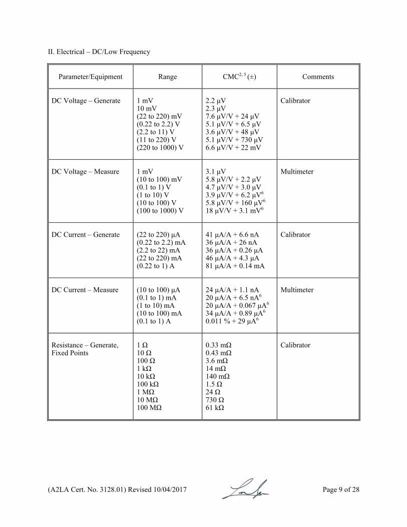
II. Electrical – DC/Low Frequency
Parameter/Equipment
Range CMC2, 5 (±)
Comments
DC Voltage – Generate
1 mV 10 mV (22 to 220) mV (0.22 to 2.2) V (2.2 to 11) V (11 to 220) V (220 to 1000) V
2.2 μV 2.3 μV 7.6 μV/V + 24 μV 5.1 μV/V + 6.5 μV 3.6 μV/V + 48 μV 5.1 μV/V + 730 μV 6.6 μV/V + 22 mV
Calibrator
DC Voltage – Measure
1 mV (10 to 100) mV (0.1 to 1) V (1 to 10) V (10 to 100) V (100 to 1000) V
3.1 μV 5.8 μV/V + 2.2 μV 4.7 μV/V + 3.0 μV 3.9 μV/V + 6.2 μV6 5.8 μV/V + 160 μV6 18 μV/V + 3.1 mV6
Multimeter
DC Current – Generate
(22 to 220) μA (0.22 to 2.2) mA (2.2 to 22) mA (22 to 220) mA (0.22 to 1) A
41 μA/A + 6.6 nA 36 μA/A + 26 nA 36 μA/A + 0.26 μA 46 μA/A + 4.3 μA 81 μA/A + 0.14 mA
Calibrator
DC Current – Measure
(10 to 100) μA (0.1 to 1) mA (1 to 10) mA (10 to 100) mA (0.1 to 1) A
24 μA/A + 1.1 nA 20 μA/A + 6.5 nA6 20 μA/A + 0.067 μA6
34 μA/A + 0.89 μA6 0.011 % + 29 μA6
Multimeter
Resistance – Generate, Fixed Points
1 Ω 10 Ω 100 Ω 1 kΩ 10 kΩ 100 kΩ 1 MΩ 10 MΩ 100 MΩ
0.33 mΩ 0.43 mΩ 3.6 mΩ 14 mΩ 140 mΩ 1.5 Ω 24 Ω 730 Ω 61 kΩ
Calibrator
(A2LA Cert. No. 3128.01) Revised 10/04/2017 Page 10 of 28
Parameter/Equipment
Range CMC2, 5 (±)
Comments
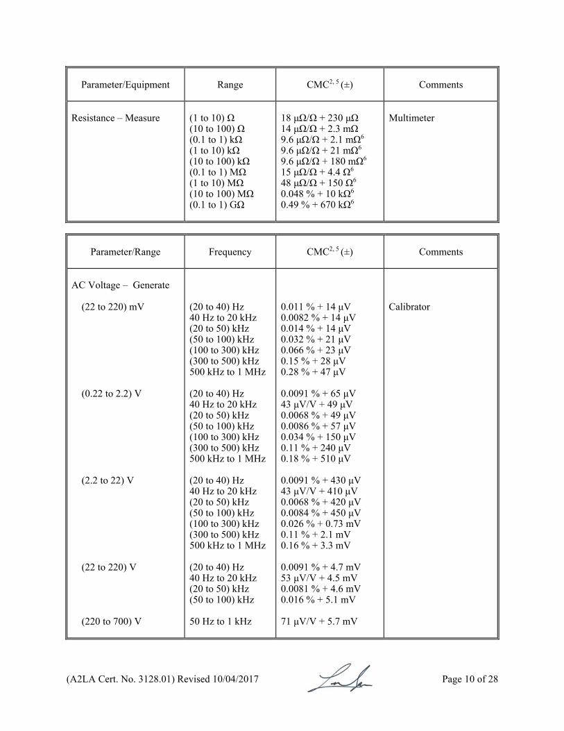
Resistance – Measure
(1 to 10) Ω (10 to 100) Ω (0.1 to 1) kΩ (1 to 10) kΩ (10 to 100) kΩ (0.1 to 1) MΩ (1 to 10) MΩ (10 to 100) MΩ (0.1 to 1) GΩ
18 μΩ/Ω + 230 μΩ 14 μΩ/Ω + 2.3 mΩ 9.6 μΩ/Ω + 2.1 mΩ6 9.6 μΩ/Ω + 21 mΩ6 9.6 μΩ/Ω + 180 mΩ6 15 μΩ/Ω + 4.4 Ω6 48 μΩ/Ω + 150 Ω6 0.048 % + 10 kΩ6 0.49 % + 670 kΩ6
Multimeter
Parameter/Range
Frequency CMC2, 5 (±)
Comments
AC Voltage – Generate (22 to 220) mV (0.22 to 2.2) V (2.2 to 22) V (22 to 220) V (220 to 700) V
(20 to 40) Hz 40 Hz to 20 kHz (20 to 50) kHz (50 to 100) kHz (100 to 300) kHz (300 to 500) kHz 500 kHz to 1 MHz (20 to 40) Hz 40 Hz to 20 kHz (20 to 50) kHz (50 to 100) kHz (100 to 300) kHz (300 to 500) kHz 500 kHz to 1 MHz (20 to 40) Hz 40 Hz to 20 kHz (20 to 50) kHz (50 to 100) kHz (100 to 300) kHz (300 to 500) kHz 500 kHz to 1 MHz (20 to 40) Hz 40 Hz to 20 kHz (20 to 50) kHz (50 to 100) kHz 50 Hz to 1 kHz
0.011 % + 14 μV 0.0082 % + 14 μV 0.014 % + 14 μV 0.032 % + 21 μV 0.066 % + 23 μV 0.15 % + 28 μV 0.28 % + 47 μV 0.0091 % + 65 μV 43 μV/V + 49 μV 0.0068 % + 49 μV 0.0086 % + 57 μV 0.034 % + 150 μV 0.11 % + 240 μV 0.18 % + 510 μV 0.0091 % + 430 μV 43 μV/V + 410 μV 0.0068 % + 420 μV 0.0084 % + 450 μV 0.026 % + 0.73 mV 0.11 % + 2.1 mV 0.16 % + 3.3 mV 0.0091 % + 4.7 mV 53 μV/V + 4.5 mV 0.0081 % + 4.6 mV 0.016 % + 5.1 mV 71 μV/V + 5.7 mV
Calibrator
(A2LA Cert. No. 3128.01) Revised 10/04/2017 Page 11 of 28
Parameter/Equipment
Frequency CMC2, 5 (±)
Comments
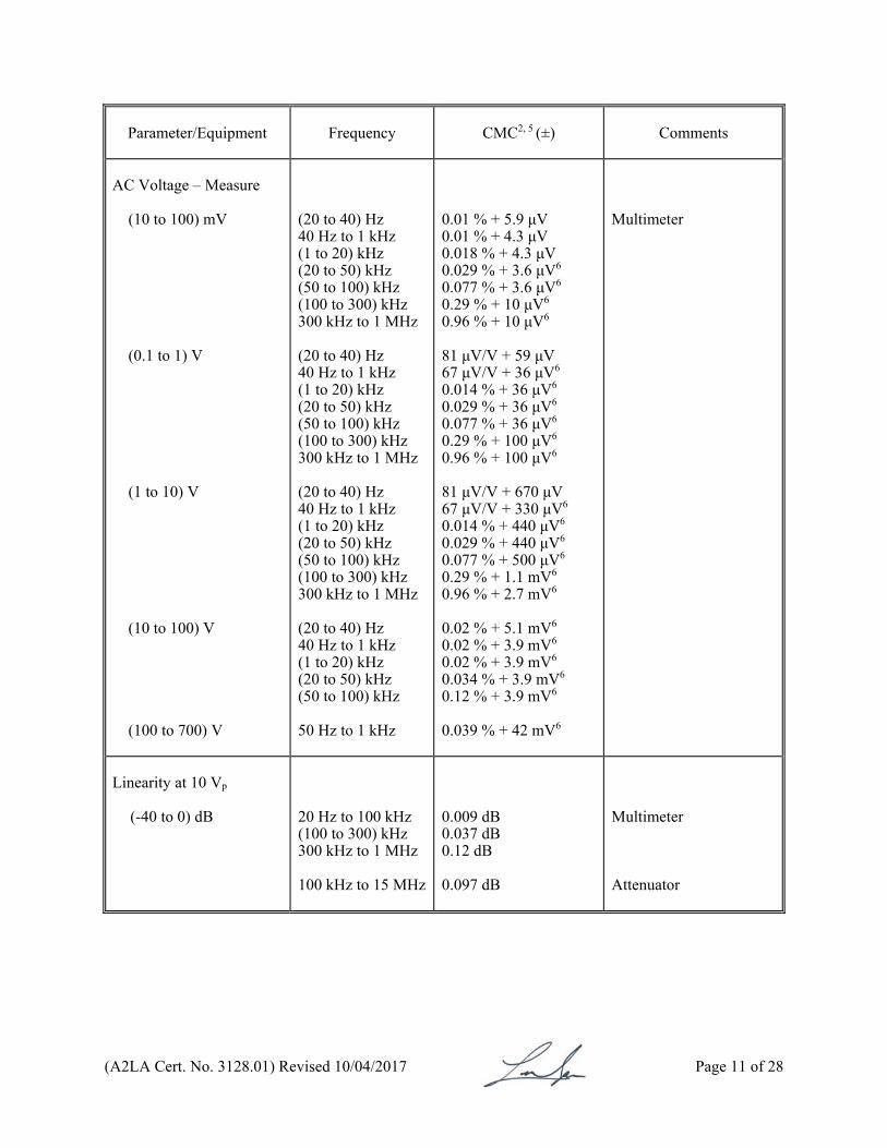
AC Voltage – Measure (10 to 100) mV (0.1 to 1) V (1 to 10) V (10 to 100) V (100 to 700) V
(20 to 40) Hz 40 Hz to 1 kHz (1 to 20) kHz (20 to 50) kHz (50 to 100) kHz (100 to 300) kHz 300 kHz to 1 MHz (20 to 40) Hz 40 Hz to 1 kHz (1 to 20) kHz (20 to 50) kHz (50 to 100) kHz (100 to 300) kHz 300 kHz to 1 MHz (20 to 40) Hz 40 Hz to 1 kHz (1 to 20) kHz (20 to 50) kHz (50 to 100) kHz (100 to 300) kHz 300 kHz to 1 MHz (20 to 40) Hz 40 Hz to 1 kHz (1 to 20) kHz (20 to 50) kHz (50 to 100) kHz 50 Hz to 1 kHz
0.01 % + 5.9 μV 0.01 % + 4.3 μV 0.018 % + 4.3 μV 0.029 % + 3.6 μV6 0.077 % + 3.6 μV6 0.29 % + 10 μV6 0.96 % + 10 μV6 81 μV/V + 59 μV 67 μV/V + 36 μV6
0.014 % + 36 μV6 0.029 % + 36 μV6 0.077 % + 36 μV6 0.29 % + 100 μV6 0.96 % + 100 μV6 81 μV/V + 670 μV 67 μV/V + 330 μV6 0.014 % + 440 μV6 0.029 % + 440 μV6 0.077 % + 500 μV6 0.29 % + 1.1 mV6 0.96 % + 2.7 mV6 0.02 % + 5.1 mV6 0.02 % + 3.9 mV6 0.02 % + 3.9 mV6 0.034 % + 3.9 mV6 0.12 % + 3.9 mV6 0.039 % + 42 mV6
Multimeter
Linearity at 10 Vp
(-40 to 0) dB
20 Hz to 100 kHz (100 to 300) kHz 300 kHz to 1 MHz 100 kHz to 15 MHz
0.009 dB 0.037 dB 0.12 dB 0.097 dB
Multimeter Attenuator
(A2LA Cert. No. 3128.01) Revised 10/04/2017 Page 12 of 28
Parameter/Equipment
Frequency CMC2, 5 (±)
Comments
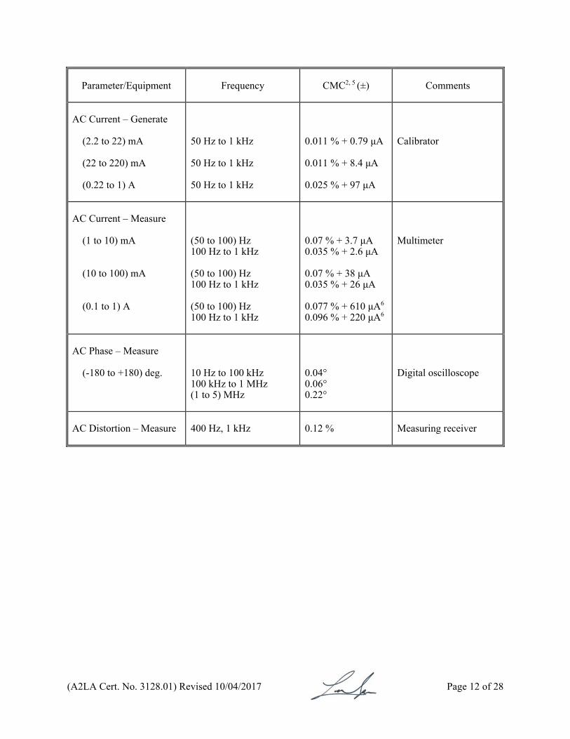
AC Current – Generate (2.2 to 22) mA (22 to 220) mA (0.22 to 1) A
50 Hz to 1 kHz 50 Hz to 1 kHz 50 Hz to 1 kHz
0.011 % + 0.79 μA 0.011 % + 8.4 μA 0.025 % + 97 μA
Calibrator
AC Current – Measure (1 to 10) mA (10 to 100) mA (0.1 to 1) A
(50 to 100) Hz 100 Hz to 1 kHz (50 to 100) Hz 100 Hz to 1 kHz (50 to 100) Hz 100 Hz to 1 kHz
0.07 % + 3.7 μA 0.035 % + 2.6 μA 0.07 % + 38 μA 0.035 % + 26 μA 0.077 % + 610 μA6 0.096 % + 220 μA6
Multimeter
AC Phase – Measure (-180 to +180) deg.
10 Hz to 100 kHz 100 kHz to 1 MHz (1 to 5) MHz
0.04° 0.06° 0.22°
Digital oscilloscope
AC Distortion – Measure
400 Hz, 1 kHz
0.12 % Measuring receiver

(A2LA Cert. No. 3128.01) Revised 10/04/2017 Page 13 of 28
III. Electrical – RF/Microwave
Parameter/Frequency
Range CMC2, 4, 5 (±)
Comments
RF Power – Generate3
50 MHz 100 kHz to 5 GHz (5 to 12) GHz (12 to 14) GHz (14 to 18) GHz (18 to 25) GHz (25 to 40) GHz
100 kHz to 10 MHz (0.01 to 3) GHz (3 to 5) GHz (5 to 12) GHz (12 to 18) GHz
1 mW 0 dBm 0 dBm 0 dBm 0 dBm 0 dBm 0 dBm (-10 to 0) dBm (-100 to -10) dBm (0 to 20) dBm (-10 to 0) dBm (-100 to -10) dBm (0 to 20) dBm (-10 to 0) dBm (-100 to -10) dBm (0 to 20) dBm (-10 to 0) dBm (-100 to -10) dBm (0 to 20) dBm (-10 to 0) dBm (-100 to -10) dBm
0.53 % 0.08 dB 0.09 dB 0.09 dB 0.12 dB 0.14 dB 0.16 dB 0.08 dB 0.10 dB 0.10 dB 0.07 dB 0.09 dB 0.12 dB 0.07 dB 0.08 dB 0.16 dB 0.09 dB 0.10 dB 0.17 dB 0.12 dB 0.13 dB
Reference oscillator Power meter and power sensor Power meter and power sensor, measuring receiver, signal analyzer
(A2LA Cert. No. 3128.01) Revised 10/04/2017 Page 14 of 28
Parameter/Frequency
Range CMC2, 4, 5 (±)
Comments
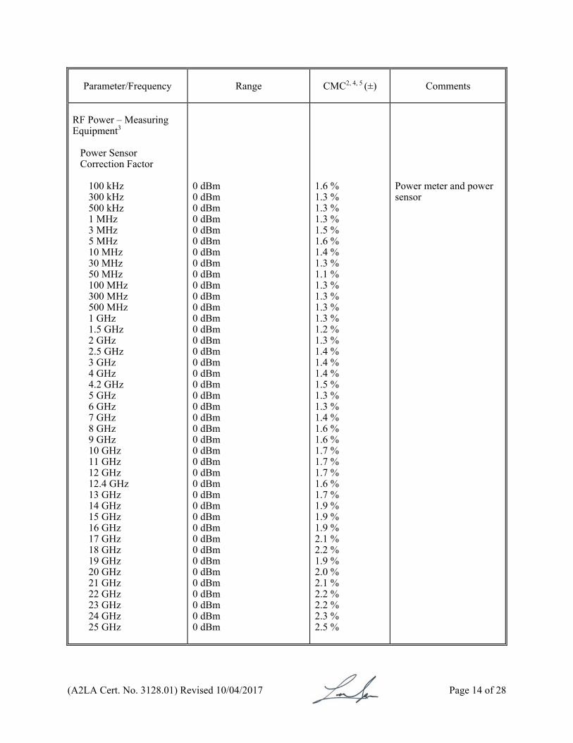
RF Power – Measuring Equipment3
Power Sensor Correction Factor
100 kHz 300 kHz 500 kHz 1 MHz 3 MHz 5 MHz 10 MHz 30 MHz 50 MHz 100 MHz 300 MHz 500 MHz 1 GHz 1.5 GHz 2 GHz 2.5 GHz 3 GHz 4 GHz 4.2 GHz 5 GHz 6 GHz 7 GHz 8 GHz 9 GHz 10 GHz 11 GHz 12 GHz 12.4 GHz 13 GHz 14 GHz 15 GHz 16 GHz 17 GHz 18 GHz 19 GHz 20 GHz 21 GHz 22 GHz 23 GHz 24 GHz 25 GHz
0 dBm 0 dBm 0 dBm 0 dBm 0 dBm 0 dBm 0 dBm 0 dBm 0 dBm 0 dBm 0 dBm 0 dBm 0 dBm 0 dBm 0 dBm 0 dBm 0 dBm 0 dBm 0 dBm 0 dBm 0 dBm 0 dBm 0 dBm 0 dBm 0 dBm 0 dBm 0 dBm 0 dBm 0 dBm 0 dBm 0 dBm 0 dBm 0 dBm 0 dBm 0 dBm 0 dBm 0 dBm 0 dBm 0 dBm 0 dBm 0 dBm
1.6 % 1.3 % 1.3 % 1.3 % 1.5 % 1.6 % 1.4 % 1.3 % 1.1 % 1.3 % 1.3 % 1.3 % 1.3 % 1.2 % 1.3 % 1.4 % 1.4 % 1.4 % 1.5 % 1.3 % 1.3 % 1.4 % 1.6 % 1.6 % 1.7 % 1.7 % 1.7 % 1.6 % 1.7 % 1.9 % 1.9 % 1.9 % 2.1 % 2.2 % 1.9 % 2.0 % 2.1 % 2.2 % 2.2 % 2.3 % 2.5 %
Power meter and power sensor
(A2LA Cert. No. 3128.01) Revised 10/04/2017 Page 15 of 28
Parameter/Frequency
Range CMC2, 4, 5 (±)
Comments
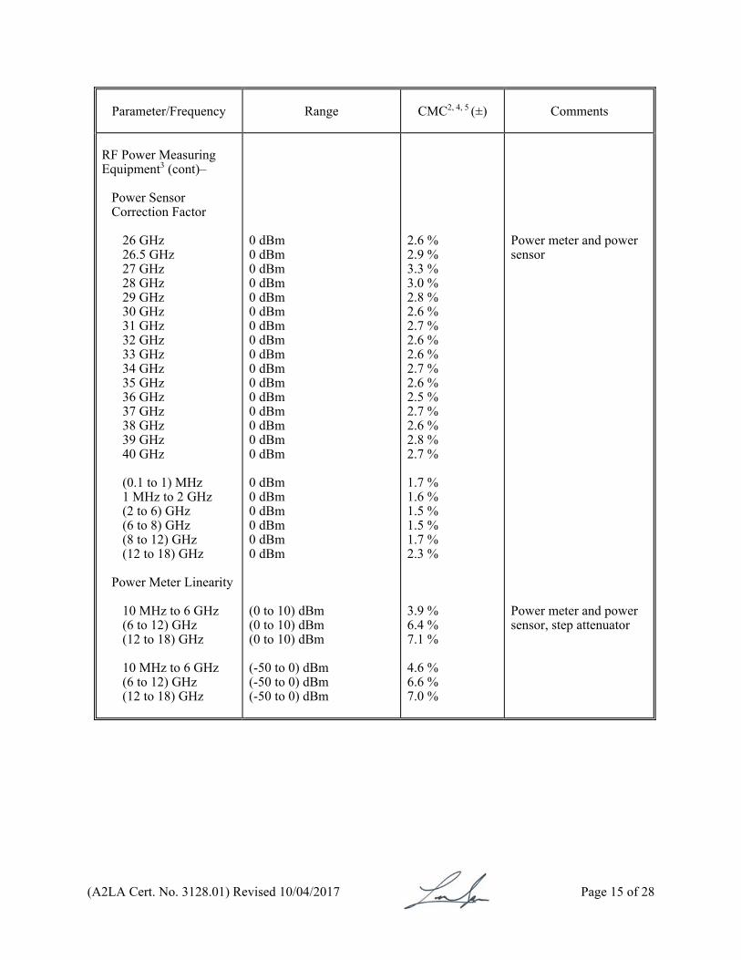
RF Power Measuring Equipment3 (cont)–
Power Sensor Correction Factor
26 GHz 26.5 GHz 27 GHz 28 GHz 29 GHz 30 GHz 31 GHz 32 GHz 33 GHz 34 GHz 35 GHz 36 GHz 37 GHz 38 GHz 39 GHz 40 GHz (0.1 to 1) MHz 1 MHz to 2 GHz (2 to 6) GHz (6 to 8) GHz (8 to 12) GHz (12 to 18) GHz
Power Meter Linearity
10 MHz to 6 GHz (6 to 12) GHz (12 to 18) GHz 10 MHz to 6 GHz (6 to 12) GHz (12 to 18) GHz
0 dBm 0 dBm 0 dBm 0 dBm 0 dBm 0 dBm 0 dBm 0 dBm 0 dBm 0 dBm 0 dBm 0 dBm 0 dBm 0 dBm 0 dBm 0 dBm 0 dBm 0 dBm 0 dBm 0 dBm 0 dBm 0 dBm (0 to 10) dBm (0 to 10) dBm (0 to 10) dBm (-50 to 0) dBm (-50 to 0) dBm (-50 to 0) dBm
2.6 % 2.9 % 3.3 % 3.0 % 2.8 % 2.6 % 2.7 % 2.6 % 2.6 % 2.7 % 2.6 % 2.5 % 2.7 % 2.6 % 2.8 % 2.7 % 1.7 % 1.6 % 1.5 % 1.5 % 1.7 % 2.3 % 3.9 % 6.4 % 7.1 % 4.6 % 6.6 % 7.0 %
Power meter and power sensor Power meter and power sensor, step attenuator

(A2LA Cert. No. 3128.01) Revised 10/04/2017 Page 16 of 28
Parameter/Frequency
Range CMC2, 5 (±)
Comments
Frequency Modulation – Measure
(0.25 to 10) MHz Rate: 20 Hz to 10 kHz (10 to 1300) MHz Rate: 20 Hz to 200 kHz (10 to 1300) MHz Rate: 50 Hz to 100 kHz
Deviation: (0.3 to 4) kHz Deviation: (4 to 40) kHz Deviation: (0.3 to 4) kHz Deviation: (4 to 40) kHz Deviation: (40 to 400) kHz Deviation: (0.3 to 4) kHz Deviation: (4 to 40) kHz Deviation: (40 to 400) kHz
3.4 % + 1 Hz 2.6 % + 10 Hz 6.3 % + 1 Hz 5.9 % + 10 Hz 5.9 % + 100 Hz 2.5 % + 1 Hz 2.1 % + 10 Hz 1.4 % + 100 Hz
Measuring receiver
Frequency Modulation – Measuring Equipment
(0.25 to 10) MHz Rate: 20 Hz to 10 kHz (10 to 1300) MHz Rate: 20 Hz to 200 kHz (10 to 1300) MHz Rate: 50 Hz to 100 kHz
Deviation: (0.3 to 4) kHz Deviation: (4 to 40) kHz Deviation: (0.3 to 4) kHz Deviation: (4 to 40) kHz Deviation: (40 to 400) kHz Deviation: (0.3 to 4) kHz Deviation: (4 to 40) kHz Deviation: (40 to 400) kHz
3.3 % + 1 Hz 2.5 % + 10 Hz 6.3 % + 1 Hz 6.0 % + 10 Hz 5.9 % + 100 Hz 2.5 % + 1 Hz 2.1 % + 10 Hz 1.4 % + 100 Hz
Measuring receiver
Attenuation – Measure
10 MHz to 18 GHz
(0 to 90) dB (90 to 100) dB
0.08 dB 0.1 dB
Measuring receiver
Attenuation – Measuring Equipment
10 MHz to 12 GHz (12 to 18) GHz
(0 to 100) dB (0 to 100) dB
0.24 dB 0.34 dB
Step attenuator
(A2LA Cert. No. 3128.01) Revised 10/04/2017 Page 17 of 28
Parameter/Equipment
Range CMC2, 4, 5 (±) Comments
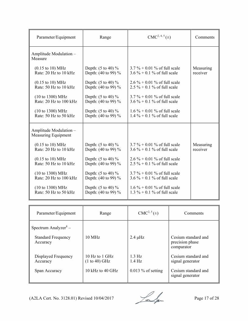
Amplitude Modulation – Measure
(0.15 to 10) MHz Rate: 20 Hz to 10 kHz (0.15 to 10) MHz Rate: 50 Hz to 10 kHz (10 to 1300) MHz Rate: 20 Hz to 100 kHz (10 to 1300) MHz Rate: 50 Hz to 50 kHz
Depth: (5 to 40) % Depth: (40 to 99) % Depth: (5 to 40) % Depth: (40 to 99) % Depth: (5 to 40) % Depth: (40 to 99) % Depth: (5 to 40) % Depth: (40 to 99) %
3.7 % + 0.01 % of full scale 3.6 % + 0.1 % of full scale 2.6 % + 0.01 % of full scale 2.5 % + 0.1 % of full scale 3.7 % + 0.01 % of full scale 3.6 % + 0.1 % of full scale 1.6 % + 0.01 % of full scale 1.4 % + 0.1 % of full scale
Measuring receiver
Amplitude Modulation – Measuring Equipment
(0.15 to 10) MHz Rate: 20 Hz to 10 kHz (0.15 to 10) MHz Rate: 50 Hz to 10 kHz (10 to 1300) MHz Rate: 20 Hz to 100 kHz (10 to 1300) MHz Rate: 50 Hz to 50 kHz
Depth: (5 to 40) % Depth: (40 to 99) % Depth: (5 to 40) % Depth: (40 to 99) % Depth: (5 to 40) % Depth: (40 to 99) % Depth: (5 to 40) % Depth: (40 to 99) %
3.7 % + 0.01 % of full scale 3.6 % + 0.1 % of full scale 2.6 % + 0.01 % of full scale 2.5 % + 0.1 % of full scale 3.7 % + 0.01 % of full scale 3.6 % + 0.1 % of full scale 1.6 % + 0.01 % of full scale 1.3 % + 0.1 % of full scale
Measuring receiver
Parameter/Equipment
Range CMC2, 5 (±)
Comments
Spectrum Analyzer8 –
Standard Frequency Accuracy Displayed Frequency Accuracy Span Accuracy
10 MHz 10 Hz to 1 GHz (1 to 40) GHz 10 kHz to 40 GHz
2.4 μHz 1.3 Hz 1.4 Hz 0.013 % of setting
Cesium standard and precision phase comparator Cesium standard and signal generator Cesium standard and signal generator
(A2LA Cert. No. 3128.01) Revised 10/04/2017 Page 18 of 28
Parameter/Equipment
Range CMC2, 4 (±)
Comments
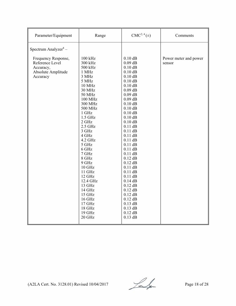
Spectrum Analyzer8 –
Frequency Response, Reference Level Accuracy, Absolute Amplitude Accuracy
100 kHz 300 kHz 500 kHz 1 MHz 3 MHz 5 MHz 10 MHz 30 MHz 50 MHz 100 MHz 300 MHz 500 MHz 1 GHz 1.5 GHz 2 GHz 2.5 GHz 3 GHz 4 GHz 4.2 GHz 5 GHz 6 GHz 7 GHz 8 GHz 9 GHz 10 GHz 11 GHz 12 GHz 12.4 GHz 13 GHz 14 GHz 15 GHz 16 GHz 17 GHz 18 GHz 19 GHz 20 GHz
0.10 dB 0.09 dB 0.10 dB 0.10 dB 0.10 dB 0.10 dB 0.10 dB 0.09 dB 0.09 dB 0.09 dB 0.10 dB 0.10 dB 0.10 dB 0.10 dB 0.10 dB 0.11 dB 0.11 dB 0.11 dB 0.11 dB 0.11 dB 0.11 dB 0.11 dB 0.12 dB 0.12 dB 0.11 dB 0.11 dB 0.11 dB 0.14 dB 0.12 dB 0.12 dB 0.12 dB 0.12 dB 0.13 dB 0.13 dB 0.12 dB 0.13 dB
Power meter and power sensor
(A2LA Cert. No. 3128.01) Revised 10/04/2017 Page 19 of 28
Parameter/Equipment
Range CMC2, 4 (±)
Comments
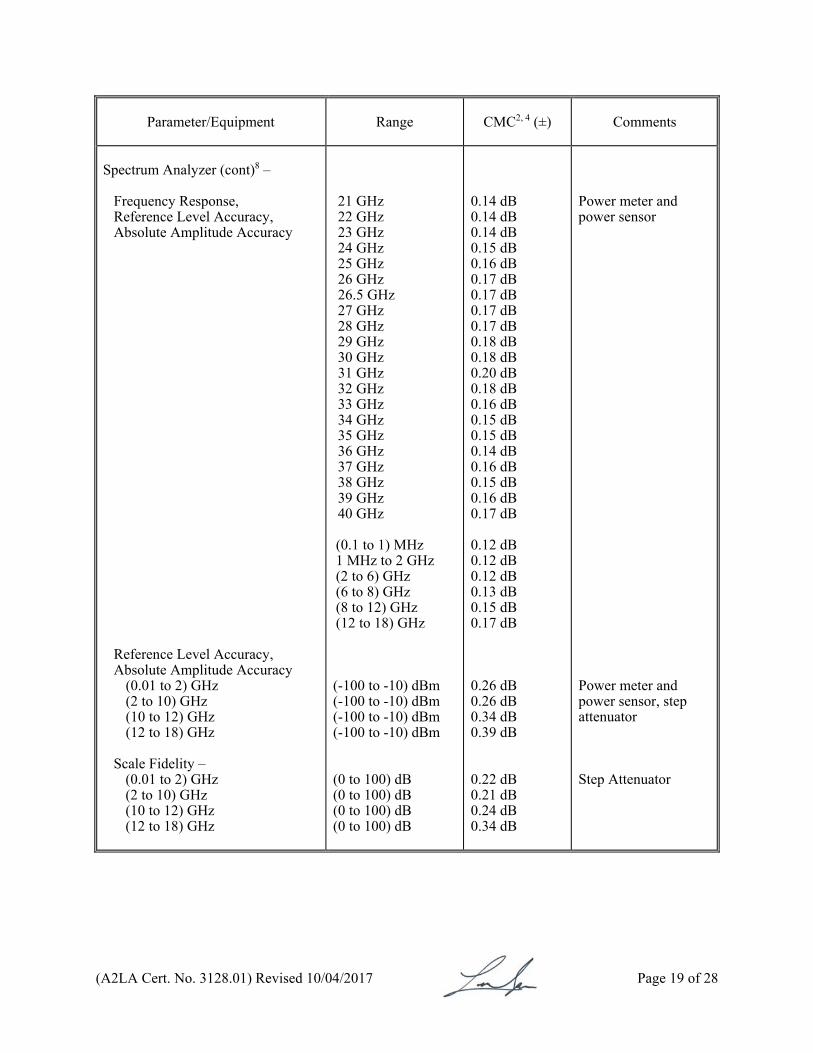
Spectrum Analyzer (cont)8 –
Frequency Response, Reference Level Accuracy, Absolute Amplitude Accuracy
Reference Level Accuracy, Absolute Amplitude Accuracy
(0.01 to 2) GHz (2 to 10) GHz (10 to 12) GHz (12 to 18) GHz
Scale Fidelity –
(0.01 to 2) GHz (2 to 10) GHz (10 to 12) GHz (12 to 18) GHz
21 GHz 22 GHz 23 GHz 24 GHz 25 GHz 26 GHz 26.5 GHz 27 GHz 28 GHz 29 GHz 30 GHz 31 GHz 32 GHz 33 GHz 34 GHz 35 GHz 36 GHz 37 GHz 38 GHz 39 GHz 40 GHz (0.1 to 1) MHz 1 MHz to 2 GHz (2 to 6) GHz (6 to 8) GHz (8 to 12) GHz (12 to 18) GHz
(-100 to -10) dBm (-100 to -10) dBm (-100 to -10) dBm (-100 to -10) dBm
(0 to 100) dB (0 to 100) dB (0 to 100) dB (0 to 100) dB
0.14 dB 0.14 dB 0.14 dB 0.15 dB 0.16 dB 0.17 dB 0.17 dB 0.17 dB 0.17 dB 0.18 dB 0.18 dB 0.20 dB 0.18 dB 0.16 dB 0.15 dB 0.15 dB 0.14 dB 0.16 dB 0.15 dB 0.16 dB 0.17 dB 0.12 dB 0.12 dB 0.12 dB 0.13 dB 0.15 dB 0.17 dB 0.26 dB 0.26 dB 0.34 dB 0.39 dB 0.22 dB 0.21 dB 0.24 dB 0.34 dB
Power meter and power sensor Power meter and power sensor, step attenuator Step Attenuator
(A2LA Cert. No. 3128.01) Revised 10/04/2017 Page 20 of 28
Parameter/Equipment
Range CMC2, 5 (±)
Comments
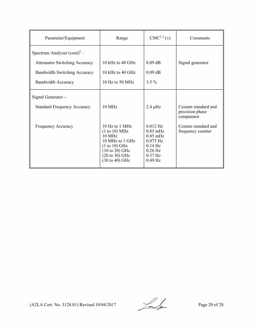
Spectrum Analyzer (cont)8 –
Attenuator Switching Accuracy Bandwidth Switching Accuracy Bandwidth Accuracy
10 kHz to 40 GHz 10 kHz to 40 GHz 10 Hz to 50 MHz
0.09 dB 0.09 dB 3.5 %
Signal generator
Signal Generator –
Standard Frequency Accuracy
Frequency Accuracy
10 MHz 10 Hz to 1 MHz (1 to 10) MHz 10 MHz 10 MHz to 1 GHz (1 to 10) GHz (10 to 20) GHz (20 to 30) GHz (30 to 40) GHz
2.4 μHz 0.012 Hz 0.85 mHz 0.85 mHz 0.075 Hz 0.14 Hz 0.26 Hz 0.37 Hz 0.49 Hz
Cesium standard and precision phase comparator Cesium standard and frequency counter
(A2LA Cert. No. 3128.01) Revised 10/04/2017 Page 21 of 28
Parameter/Equipment
Range CMC2, 4 (±)
Comments
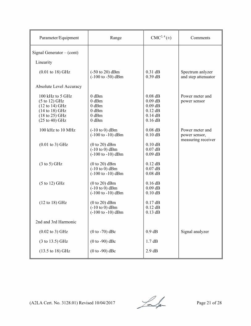
Signal Generator – (cont)
Linearity
(0.01 to 18) GHz
Absolute Level Accuracy 100 kHz to 5 GHz (5 to 12) GHz (12 to 14) GHz (14 to 18) GHz (18 to 25) GHz (25 to 40) GHz 100 kHz to 10 MHz
(0.01 to 3) GHz (3 to 5) GHz
(5 to 12) GHz (12 to 18) GHz
2nd and 3rd Harmonic (0.02 to 3) GHz (3 to 13.5) GHz (13.5 to 18) GHz
(-50 to 20) dBm (-100 to -50) dBm 0 dBm 0 dBm 0 dBm 0 dBm 0 dBm 0 dBm (-10 to 0) dBm (-100 to -10) dBm (0 to 20) dBm (-10 to 0) dBm (-100 to -10) dBm (0 to 20) dBm (-10 to 0) dBm (-100 to -10) dBm (0 to 20) dBm (-10 to 0) dBm (-100 to -10) dBm (0 to 20) dBm (-10 to 0) dBm (-100 to -10) dBm (0 to -70) dBc (0 to -90) dBc (0 to -90) dBc
0.31 dB 0.39 dB 0.08 dB 0.09 dB 0.09 dB 0.12 dB 0.14 dB 0.16 dB 0.08 dB 0.10 dB 0.10 dB 0.07 dB 0.09 dB 0.12 dB 0.07 dB 0.08 dB 0.16 dB 0.09 dB 0.10 dB 0.17 dB 0.12 dB 0.13 dB 0.9 dB 1.7 dB 2.9 dB
Spectrum anlyzer and step attenuator Power meter and power sensor Power meter and power sensor, measuring receiver Signal analyzer

(A2LA Cert. No. 3128.01) Revised 10/04/2017 Page 22 of 28
Parameter/Equipment
Range CMC2, 4, 5 (±)
Comments
Signal Generator – (cont)
FM Modulation Accuracy
(0.25 to 10) MHz Mod. Frequency: 20 Hz to 10 kHz (10 to 1300) MHz Mod. Frequency: 20 Hz to 200 kHz (10 to 1300) MHz Mod. Frequency: 50 Hz to 100 kHz
Deviation: (0.3 to 4) kHz Deviation: (4 to 40) kHz Deviation: (0.3 to 4) kHz Deviation: (4 to 40) kHz Deviation: (40 to 400) kHz Deviation: (0.3 to 4) kHz Deviation: (4 to 40) kHz Deviation: (40 to 400) kHz
3.4 % + 1 Hz 2.6 % + 10 Hz 6.3 % + 1 Hz 5.9 % + 10 Hz 5.9 % + 100 Hz 2.5 % + 1 Hz 2.1 % + 10 Hz 1.4 % + 100 Hz
Measuring receiver
Signal Generator – (cont)
AM Modulation Accuracy
(0.15 to 10) MHz Rate: 20 Hz to 10 kHz (0.15 to 10) MHz Rate: 50 Hz to 10 kHz (10 to 1300) MHz Rate: 20 Hz to 100 kHz (10 to 1300) MHz Rate: 50 Hz to 50 kHz
Depth: (5 to 40) % Depth: (40 to 99) % Depth: (5 to 40) % Depth: (40 to 99) % Depth: (5 to 40) % Depth: (40 to 99) % Depth: (5 to 40) % Depth: (40 to 99) %
3.7 % + 0.01 % of full scale 3.6 % + 0.1 % of full scale 2.6 % + 0.01 % of full scale 2.5 % + 0.1 % of full scale 3.7 % + 0.01 % of full scale 3.6 % + 0.1 % of full scale 1.6 % + 0.01 % of full scale 1.4 % + 0.1 % of full scale
Measuring receiver

(A2LA Cert. No. 3128.01) Revised 10/04/2017 Page 23 of 28
Parameter/Equipment
Range CMC2, 4 (±)
Comments
Attenuator – Attenuation Accuracy
10 MHz to 18 GHz
(0 to 90) dB (90 to 100) dB
0.08 dB 0.1 dB
Measuring receiver
Parameter/Frequency
Range CMC2 (±)
Comments
S Parameters for S11, S12, S21, S22
Reflection S11/S22 Magnitude and Phase – Measure9
(70 to 300) kHz
(0.0001 to 0.03) lin (0.03 to 0.1) lin (0.1 to 0.2) lin (0.2 to 0.5) lin (0.5 to 1) lin
(0.005 to 0.011) lin (90 to 13) deg (0.005 to 0.011) lin (13 to 4.2) deg (0.005 to 0.011) lin (4.2 to 2.3) deg (0.005 to 0.011) lin (2.3 to 0.82) deg (0.008 to 0.021) lin (2.3 to 0.82) deg
VNA: MS4644A calibration kit : 3652A, 3652A-1, 3653, 3653A Verification kit: 3668-1
(A2LA Cert. No. 3128.01) Revised 10/04/2017 Page 24 of 28
Parameter/Frequency
Range CMC2 (±)
Comments
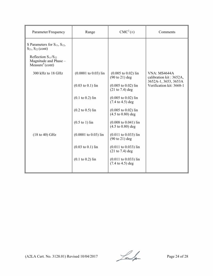
S Parameters for S11, S12, S21, S22 (cont)
Reflection S11/S22 Magnitude and Phase – Measure9 (cont)
300 kHz to 18 GHz (18 to 40) GHz
(0.0001 to 0.03) lin (0.03 to 0.1) lin (0.1 to 0.2) lin (0.2 to 0.5) lin (0.5 to 1) lin (0.0001 to 0.03) lin (0.03 to 0.1) lin (0.1 to 0.2) lin
(0.005 to 0.02) lin (90 to 21) deg (0.005 to 0.02) lin (21 to 7.4) deg (0.005 to 0.02) lin (7.4 to 4.5) deg (0.005 to 0.02) lin (4.5 to 0.80) deg (0.008 to 0.041) lin (4.5 to 0.80) deg (0.011 to 0.033) lin (90 to 21) deg (0.011 to 0.033) lin (21 to 7.4) deg (0.011 to 0.033) lin (7.4 to 4.5) deg
VNA: MS4644A calibration kit : 3652A, 3652A-1, 3653, 3653A Verification kit: 3668-1
(A2LA Cert. No. 3128.01) Revised 10/04/2017 Page 25 of 28
Parameter/Frequency
Range CMC2 (±)
Comments
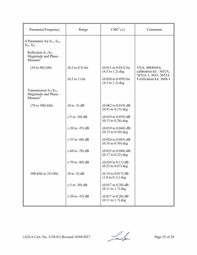
S Parameters for S11, S12, S21, S22
Reflection S11/S22 Magnitude and Phase – Measure9
(18 to 40) GHz Transmission S12/S21, Magnitude and Phase – Measure9
(70 to 300) kHz 300 kHz to 18 GHz
(0.2 to 0.5) lin (0.5 to 1) lin (0 to -5) dB (-5 to -30) dB (-30 to -35) dB (-35 to -60) dB (-60 to -70) dB (-70 to -80) dB (0 to -5) dB (-5 to -30) dB (-30 to -35) dB
(0.011 to 0.033) lin (4.5 to 1.2) deg (0.020 to 0.059) lin (4.5 to 1.2) deg (0.062 to 0.019) dB (0.41 to 0.13) deg (0.019 to 0.039) dB (0.13 to 0.26) deg (0.019 to 0.044) dB (0.13 to 0.30) deg (0.024 to 0.045) dB (0.16 to 0.30) deg (0.025 to 0.048) dB (0.17 to 0.32) deg (0.034 to 0.11) dB (0.23 to 0.67) deg (0.19 to 0.017) dB (1.8 to 0.11) deg (0.017 to 0.20) dB (0.11 to 1.7) deg (0.017 to 0.20) dB (0.11 to 1.7) deg
VNA: MS4644A calibration kit : 3652A, 3652A-1, 3653, 3653A Verification kit: 3668-1

(A2LA Cert. No. 3128.01) Revised 10/04/2017 Page 26 of 28
Parameter/Frequency
Range CMC2 (±)
Comments
S Parameters for S11, S12, S21, S22 (cont)
Transmission S12/S21, Magnitude and Phase – Measure9 (cont)
300 kHz to 18 GHz (18 to 40) GHz
(-35 to -60) dB (-60 to -70) dB (-70 to -80) dB (0 to -5) dB (-5 to -30) dB (-30 to -35) dB (-35 to -60) dB (-60 to -70) dB (-70 to -80) dB
(0.022 to 0.20) dB (0.15 to 1.7) deg (0.023 to 0.20) dB (0.16 to 1.7) deg (0.033 to 0.20) dB (0.22 to 1.9) deg (0.19 to 0.16) dB (1.8 to 1.7) deg (0.039 to 0.31) dB (0.26 to 3.3) deg (0.039 to 0.31) dB (0.26 to 3.4) deg (0.044 to 0.31) dB (0.30 to 3.4) deg (0.044 to 0.31) dB (0.30 to 3.4) deg (0.044 to 0.31) dB (0.30 to 3.4) deg
(A2LA Cert. No. 3128.01) Revised 10/04/2017 Page 27 of 28
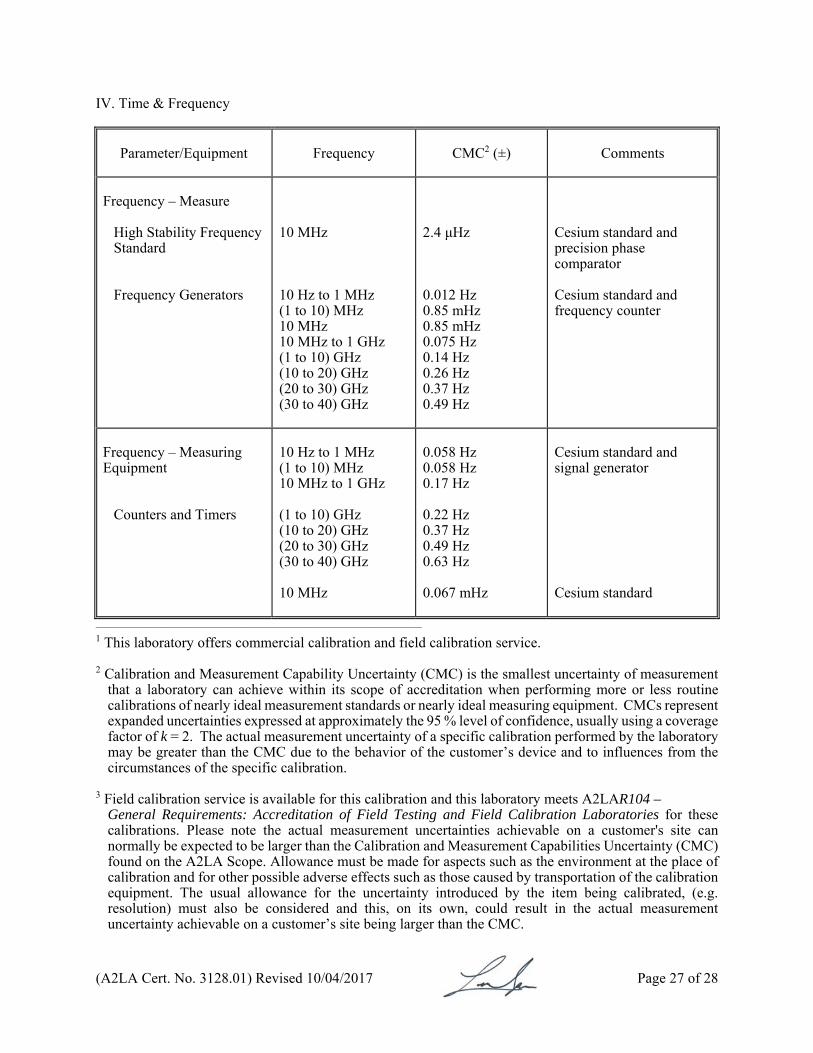
IV. Time & Frequency
Parameter/Equipment
Frequency CMC2 (±)
Comments
Frequency – Measure
High Stability Frequency Standard Frequency Generators
10 MHz 10 Hz to 1 MHz (1 to 10) MHz 10 MHz 10 MHz to 1 GHz (1 to 10) GHz (10 to 20) GHz (20 to 30) GHz (30 to 40) GHz
2.4 μHz 0.012 Hz 0.85 mHz 0.85 mHz 0.075 Hz 0.14 Hz 0.26 Hz 0.37 Hz 0.49 Hz
Cesium standard and precision phase comparator Cesium standard and frequency counter
Frequency – Measuring Equipment
Counters and Timers
10 Hz to 1 MHz (1 to 10) MHz 10 MHz to 1 GHz (1 to 10) GHz (10 to 20) GHz (20 to 30) GHz (30 to 40) GHz 10 MHz
0.058 Hz 0.058 Hz 0.17 Hz 0.22 Hz 0.37 Hz 0.49 Hz 0.63 Hz 0.067 mHz
Cesium standard and signal generator Cesium standard
______________________________________________________________________
1 This laboratory offers commercial calibration and field calibration service. 2 Calibration and Measurement Capability Uncertainty (CMC) is the smallest uncertainty of measurement
that a laboratory can achieve within its scope of accreditation when performing more or less routine calibrations of nearly ideal measurement standards or nearly ideal measuring equipment. CMCs represent expanded uncertainties expressed at approximately the 95 % level of confidence, usually using a coverage factor of k = 2. The actual measurement uncertainty of a specific calibration performed by the laboratory may be greater than the CMC due to the behavior of the customer’s device and to influences from the circumstances of the specific calibration.
3 Field calibration service is available for this calibration and this laboratory meets A2LAR104 –
General Requirements: Accreditation of Field Testing and Field Calibration Laboratories for these calibrations. Please note the actual measurement uncertainties achievable on a customer's site can normally be expected to be larger than the Calibration and Measurement Capabilities Uncertainty (CMC) found on the A2LA Scope. Allowance must be made for aspects such as the environment at the place of calibration and for other possible adverse effects such as those caused by transportation of the calibration equipment. The usual allowance for the uncertainty introduced by the item being calibrated, (e.g. resolution) must also be considered and this, on its own, could result in the actual measurement uncertainty achievable on a customer’s site being larger than the CMC.
(A2LA Cert. No. 3128.01) Revised 10/04/2017 Page 28 of 28
4 Uncertainty does not include mismatch error due to connections of the device to other devices in actual use. Mismatch uncertainties, due to the reflection coefficient of the device to be calibrated, are to be included in the overall measurement uncertainty, The approach of determining expanded uncertainties at approximately the 95% level of confidence, (using a coverage factor of k = 2) is to be applied for this calculation as well.
5 Unless otherwise defined, in the statement of CMC, the value of % is defined as the percentage of reading. 6 The coverage factor of k = 1.65 is used such that the level of confidence corresponds to approximately
95 %. 7 xx are suffix letters A to Z or number 0 to 9 for LTE RF conformance test system options. 8 Includes other frequency selective level measuring equipment like Signal Analyzers. 9 The CMC for intermediate values of measurand can be found by interpolation.
For the calibrations to which this accreditation applies, please refer to the laboratory’s Calibration Scope of Accreditation.
Accredited Laboratory
A2LA has accredited
ANRITSU CUSTOMER SUPPORT CO., LTD. Atsugi-shi, Kanagawa-Prf, JAPAN
for technical competence in the field of
Calibration
This laboratory is accredited in accordance with the recognized International Standard ISO/IEC 17025:2005 General requirements for the competence of testing and calibration laboratories. This laboratory also meets the requirements of ANSI/NCSL
Z540-1-1994 and R205 – Specific Requirements: Calibration Laboratory Accreditation Program. This accreditation demonstrates technical competence for a defined scope and the operation of a laboratory quality management system
(refer to joint ISO-ILAC-IAF Communiqué dated 8 January 2009).
Presented this 21st day of September 2017. _______________________ President and CEO For the Accreditation Council Certificate Number 3128.01 Valid to May 31, 2019