sdr
DESCRIPTION
ManualsTRANSCRIPT

Internal Only▲
Introduction to GU SDR
Base Stations
GU Product Support Dept.
Internal Only▲
Purpose
� You are expected to master the following
knowledge after this course
� basic concepts and structure of SDR
2012/6/21 22012/6/21 2
� Types of SDR base stations
� SDR hardware boards
� Interfaces of SDR base stations

内部公开 Internal Only▲
Contents
Basic Concepts of SDR
Structure of SDR Base Stations
Introduction to BBU
Introduction to RU/RRUIntroduction to RU/RRU
Introduction to Interface between BBU and RU/RRU
Special Functions of SDR Base Stations
Internal Only▲
What is SDR (1)
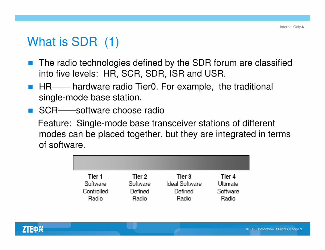
� The radio technologies defined by the SDR forum are classified
into five levels: HR, SCR, SDR, ISR and USR.
� HR—— hardware radio Tier0. For example, the traditional
single-mode base station.
� SCR——software choose radio
Feature: Single-mode base transceiver stations of different Feature: Single-mode base transceiver stations of different
modes can be placed together, but they are integrated in terms
of software.
Internal Only▲
What is SDR (2)
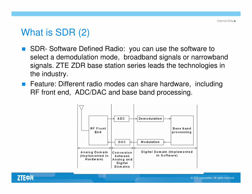
� SDR- Software Defined Radio: you can use the software to
select a demodulation mode, broadband signals or narrowband
signals. ZTE ZDR base station series leads the technologies in
the industry.
� Feature: Different radio modes can share hardware, including
RF front end, ADC/DAC and base band processing.
Internal Only▲
What is SDR (3)
� ISR——Idea software radio.
Feature: 1) get rid of the analog RF front end; 2) the whole system can be
controlled by programming except the antenna.
� USR——Ultimate software radio
Feature: 1) it has the function of the ISR; 2) the controlling software should
be standardized. Switch between different radio modes can be finished within
milliseconds.
� The ISR cannot be widely used because the technology is not mature.
Internal Only▲
What is SDR (4)
� SDR and cognitive radio
� Cognitive radio is an
important technology of
USR. It can perceive the
surroundings, and adjust
the wireless bandwidth
and de-modulation mode and de-modulation mode
accordingly.
内部公开 Internal Only▲
Contents
Basic concepts of SDR
Structure of SDR Base Stations
Introduction to BBU
Introduction to RU/RRUIntroduction to RU/RRU
Introduction to Interface between BBU and RU/RRU
Special Functions of SDR Base Stations
Internal Only▲
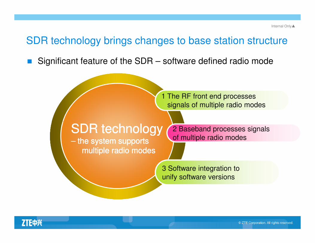
SDR technology brings changes to base station structure
� Significant feature of the SDR – software defined radio mode
1 The RF front end processes
signals of multiple radio modes
SDR technologySDR technologySDR technologySDR technology 2 Baseband processes signals
of multiple radio modes
3 Software integration to
unify software versions
SDR technologySDR technology–– the system supports the system supports
multiple radio modesmultiple radio modes
SDR technologySDR technology–– the system supports the system supports
multiple radio modesmultiple radio modes

Internal Only▲
Market drives changes to the base station structure
Green base
station
Cut cost
StructureStructure
A B
StructureStructure
Compatible
DWireless
integration,
IP technology
C

Internal Only▲
Structure of ZTE SDR base station
� Support the distributed structure of BBU and RRU. For
traditional base stations, BBU and RRU should be in the same
module.
� Multi-mode base band pool BBU
� Multi-mode RF platform
� Adopt IP technology to process internal data stream of the base � Adopt IP technology to process internal data stream of the base
station
� OMC platform——OMCR and OMCB
� Unified software platform

Internal Only▲
ANT
Transceiver Duplex
Multi-
carrier PA
RRU/RU
BBU baseband pool
Fiber
SDR product structure
Transceiver
Front end of Rx
Duplex
External power PWS220VAC
BBUBBU
Resource
control board
Internal Only▲
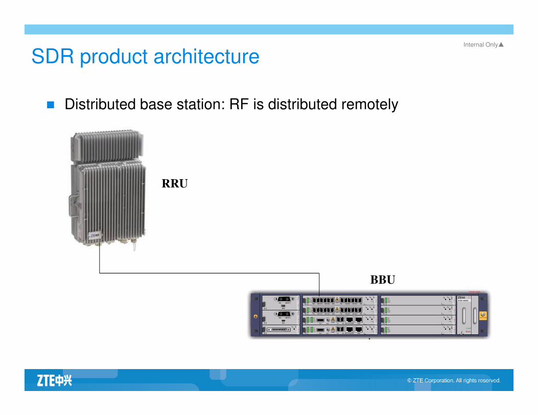
SDR product architecture
� Distributed base station: RF is distributed remotely
RRU
BBU

Internal Only▲
SDR product architecture
� Macro base station: BBU and RU are all in the cabinet, which is
different from the distributed base station in structure.

Internal Only▲Advantage 1 of the SDR architecture – BBU and
RRU can be distributed separately
� In this mode, both BBU and RRU and maximize their
efficiency. BBU can achieve the maximum integration,
and RRU can focus on the power of itself.
� The networking is flexible if the RRU is distributed
remotely. For example, it can support multi-carrier and
indoor distributed coverage.
� BBU and RRU can be distributed flexibly, which benefit
for compatibility design.

Internal Only▲
Advantage 2 of the SDR architecture – baseband hardware
� Support multiple radio modes
� Simple design
� Powerful processing capability
� Easy to manage
� Easy to share resources� Easy to share resources
� Cut cost
� Easy for evolution of baseband technologies
Internal Only▲
Advantage 3 of the SDR architecture – independent RF unit
� Simplified functions
� Improved reliability, easy for maintenance
� Improved the efficiency of the power amplifier
� Optimized heat design, easy for integration
� Closer to antenna, hence bigger power� Closer to antenna, hence bigger power
� Flexible forms of RU/RRU products
� Help to reduce the size and weight of base stations
� Cut cost

Internal Only▲
Advantage 4 of the SDR architecture – unified interface between
BBU and RU/RRU
� The interface between BBU and RU/RRU is the exclusive
interface for communication between BBU and RU/RRU .
� The interface between BBU and RU/RRU supports such radio
modes as GSM, WCDMA, TD-SCDMA, etc.
� Support fiber interface and electrical interface
� Support 1.2288Gbps and 2.4576Gbps rate� Support 1.2288Gbps and 2.4576Gbps rate
� Support RU/RRU cascading-connection
� RRU can be distributed remotely. BBU should keep 40 km
away from RRU.
Internal Only▲
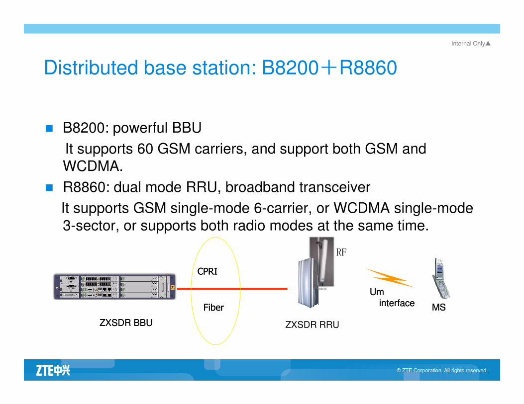
Distributed base station: B8200+R8860
� B8200: powerful BBU
It supports 60 GSM carriers, and support both GSM and
WCDMA.
� R8860: dual mode RRU, broadband transceiver
It supports GSM single-mode 6-carrier, or WCDMA single-mode It supports GSM single-mode 6-carrier, or WCDMA single-mode
3-sector, or supports both radio modes at the same time.
ZXSDR BBUZXSDR BBU ZXSDR RRU
RF
MSMS
UmUminterfaceinterface
CPRICPRI
FiberFiber

Internal Only▲
Indoor dual-mode macro base station – ZXSDR BS8800
� Size: main cabinet 950×600×450 mm
extension cabinet 700×600×450 mm
� Weight: main cabinet ≤ 150Kg
extension cabinet ≤ 130Kg
� Power: S12/12/12: 1335W
S6/6/6: 825WS6/6/6: 825W
� Input voltage: -48VDC (-40~ -57VDC)
� Transmission mode: the Abis interface supports 8 E1/T1 links
and 1 GE port.
� Maximum site configuration: S12/12/12 or O36

Internal Only▲
Software architecture of the SDR base station – OMC software
Internal Only▲
Software architecture of the SDR base station – OMC software 2
� OMCB is an operation and maintenance unit to manage NodeB in
3GPP. ZTE’s SDR base stations support both radio modes of GSM
and WCDMA. Connection mode of the traditional base station: OMCR-
>BSC->BTS; Connection mode of the SDR: OMCB->BTS, OMCR-
>BSC->BTS.>BSC->BTS.
� According to the management mode of WCDMA, the board
management, configuration, software downloading and alarms are all
managed by OMCB. In case of the dual-mode, operation and
maintenance tasks of GSM are moved to OMCB, and OMCR manages
GSM related radio configuration and status management.
Internal Only▲
Software architecture of the SDR base station – OMC software 3
� OMCR connects to BTS through BSC, regardless the link status
between BSC and BTS. OMCR sends data to BSC, who then
synchronizes the data to BTS.
� OMCB is different from OMCR. OMCB interacts with SDR through IP
links. The interaction between OMCB and SDR may pass or not pass links. The interaction between OMCB and SDR may pass or not pass
through BSC/RNC. OMCB and SDR confirm data transmission only,
and BSC/RNC needs not to make confirmation. Physically, OMCB can
interact with SDR through IP routes provided by BSC/RNC.
� For dual-mode sites, some OMCB connects with BSC, and some
OMCB connects with RNC. BSC/RNC then connects with SDR
through IP transmission.
Internal Only▲
Software architecture of the SDR base station – OMC software 4
� OMCB and OMCR can share the same server or board, but they are two different programs and there is no direct interaction between them. Hence, it is necessary to guarantee data consistent manually. Theoretically, the basic board information is configured on OMCB, and the logic information is configured on OMCR. If data are inconsistent between them, we will take the data on OMCB as the reference data.
� The main control board of the SDR will keep a copy of all configuration � The main control board of the SDR will keep a copy of all configuration data of the OMCB. Hence, the data takes effect directly when the SDR starts, without direct interaction between the SDR and OMCB. Then, the SDR creates a link to BSC and requests for radio parameters, and BSC sends the data except configuration information of OMCB to the SDR. Thus, a complete data configuration table is generated. That is a theoretic process. In practice, it is necessary to modify the data configuration. For example, modify radio parameters for expansion projects. Data configuration of OMCB should be compatible with that of OMCR, otherwise, the SDR cannot respond correctly.

Internal Only▲
Media plane of the SDR
� The media plane supports transmission by the RTP protocol
� The UBPG of SDR and the BIPB of iBSC process RTP data of the user plane.
� CC is responsible for forwarding messages inside the BBU and over the Abis interface.
内部公开 Internal Only▲
Contents
Basic Concepts of SDR
Structure of SDR Base Stations
Introduction to BBU
Introduction to RU/RRUIntroduction to RU/RRU
Introduction to Interface between BBU and RU/RRU
Special Functions of SDR Base Stations
Internal Only▲
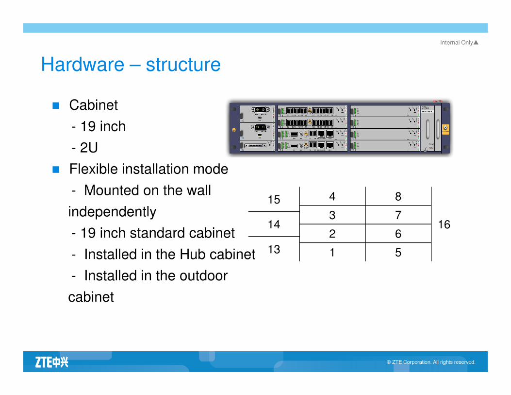
Hardware – structure
� Cabinet
- 19 inch
- 2U
� Flexible installation mode
- Mounted on the wall 15 4 8- Mounted on the wall
independently
- 19 inch standard cabinet
- Installed in the Hub cabinet
- Installed in the outdoor
cabinet
15 4 8
163 7
142 6
13 1 5
Internal Only▲
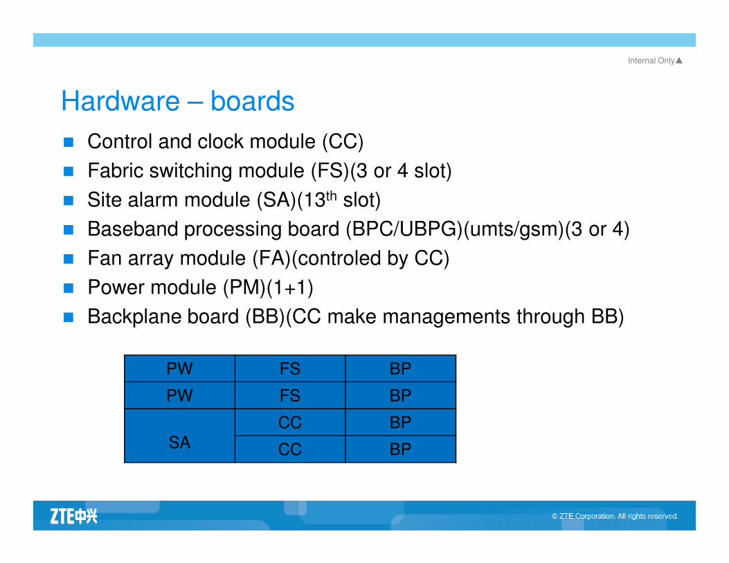
Hardware – boards
� Control and clock module (CC)
� Fabric switching module (FS)(3 or 4 slot)
� Site alarm module (SA)(13th slot)
� Baseband processing board (BPC/UBPG)(umts/gsm)(3 or 4)
� Fan array module (FA)(controled by CC)
� Power module (PM)(1+1)� Power module (PM)(1+1)
� Backplane board (BB)(CC make managements through BB)
PW FS BP
PW FS BP
SA
CC BP
CC BP
Internal Only▲
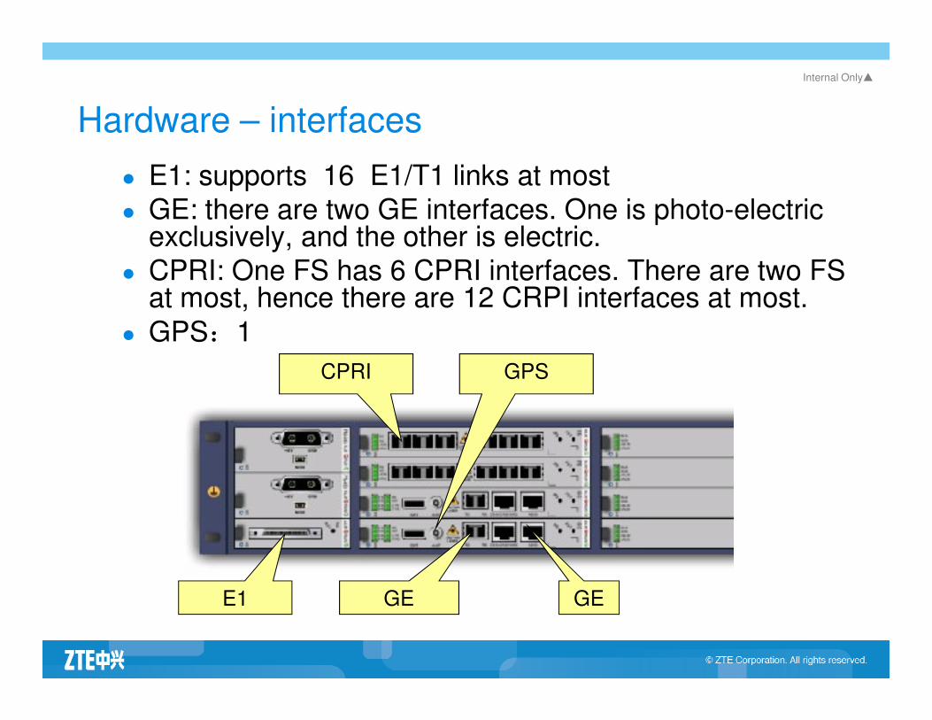
Hardware – interfaces
� E1: supports 16 E1/T1 links at most
� GE: there are two GE interfaces. One is photo-electric exclusively, and the other is electric.
� CPRI: One FS has 6 CPRI interfaces. There are two FS at most, hence there are 12 CRPI interfaces at most.
� GPS:1
CPRI GPSCPRI
GE E1 GE
GPS
Internal Only▲
Hardware function module – CC
� Integrate such functions as main control, clock, switching and the Iub/Abis interface
� Physically, the CC does not provide the E1/T1 interface. It connects E1/T1 to the SA through the backplane of BBU, and the SA provides the E1/T1 interface.
� Support the master/slave mode
� Full IP transmission� Full IP transmission
� CC0: It supports internal or external GPS, clock cascaded connection, and 16 E1 links. It does not support 2MBits clock.
� CC2: It does not support internal or external GPS and clock cascaded connection. It supports 2MBits clock and 8 E1 links.

Internal Only▲
Hardware function module – FS
� The slot for FS is also compatible for the baseband board.
� 6 1.25G CPRI optical ports, which support 24TRX (GSM) or
4CS (WCDMA) each.
� It does not support master/slave switchover.

Internal Only▲
Hardware function module – SA/SE
� Environment monitoring module
� Fan monitor
� SA: support 8 channels of E1/T1 signals, 1 RS232 serial port or
1 RS485 interface, 6 input dry contact alarm, and 2 double-
directional dry contact alarm
� SE: support 8 channels of E1/T1 signals, 1 RS232 serial port or � SE: support 8 channels of E1/T1 signals, 1 RS232 serial port or
1 RS485 interface, 6 input dry contact alarm, and 2 double-
directional dry contact alarm
Internal Only▲
Hardware function module – FA
� Fan monitoring module
� Power supply, rotation control and status report
� LEDs on the fan subrack

Internal Only▲
Hardware function module – PM
� A single PM provides 16 12V-power supply, which can meet the
power supply requirement of B8200 in full configuration.
� Two PMs working in master/slave mode
Internal Only▲
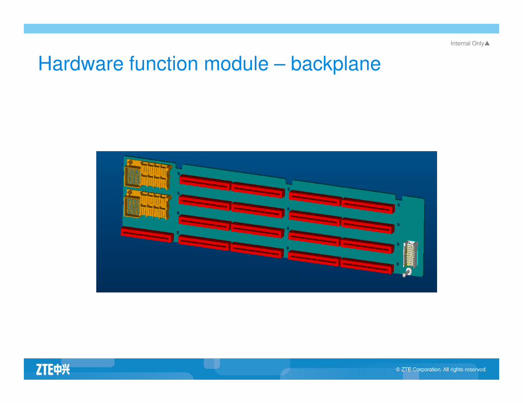
Hardware function module – backplane

Internal Only▲
BBU configuration rules
Board Configurations
Power module (PM) 1 PM is configured by default. Decide whether it is necessary to configure 2 PMs according to the requirement for reliability and cost.
Site alarm module (SA) 1 SA is configured by default.
Control and clock module (CC) 1 CC is configured by default. Select either CC0 or CC2 according to the clock and E1. Decide whether it is necessary to configure 2 CCs according to the requirement for reliability and cost.
Fabric switch module (FS) Generally, 1 FS is configured, and 2 FSs at most. The quantity depends on site configuration.
Universal baseband processing board for GSM (UBPG)
The quantity depends on site configuration.
The slots are compatible for both the BPC and the UBPG.
Baseband processing board type C (BPC)
The quantity depends on site configuration.
The slots are compatible for both the BPC and the UBPG.
Fan array module (FA) 1 FA only is configured
Site alarm extension board(SE)
Optional, which depends on the quantity of dry contacts.
It is inserted at Slot 5.

内部公开 Internal Only▲
Contents
Basic Concepts of SDR
Structure of SDR Base Stations
Introduction to BBU
Introduction to RU/RRUIntroduction to RU/RRU
Introduction to Interface between BBU and RU/RRU
Special Functions of SDR Base Stations
Internal Only▲
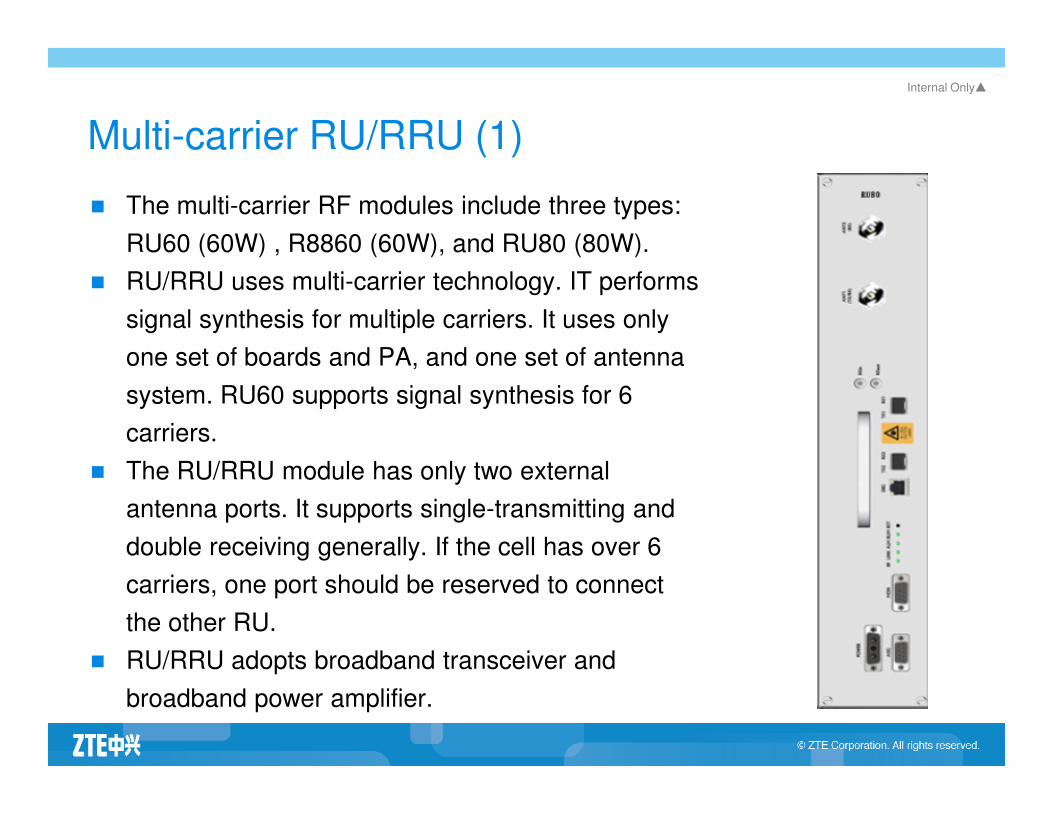
Multi-carrier RU/RRU (1)
� The multi-carrier RF modules include three types:
RU60 (60W) , R8860 (60W), and RU80 (80W).
� RU/RRU uses multi-carrier technology. IT performs
signal synthesis for multiple carriers. It uses only
one set of boards and PA, and one set of antenna
system. RU60 supports signal synthesis for 6 system. RU60 supports signal synthesis for 6
carriers.
� The RU/RRU module has only two external
antenna ports. It supports single-transmitting and
double receiving generally. If the cell has over 6
carriers, one port should be reserved to connect
the other RU.
� RU/RRU adopts broadband transceiver and
broadband power amplifier.

Internal Only▲
RU/RRU configuration rules
� RRU supports at most 4-level cascaded connection. In practice, however, it is suggested to adopt only 2-level cascaded connection in networking.
� For RRUs in cascaded connection, there is no limit to the position, sequence, frequency band, and radio mode.
� RRUs of different bands share neither antennas nor feeders.
� For multiple sets of RRUs sharing the iron tower, the isolation � For multiple sets of RRUs sharing the iron tower, the isolation between TX/Rx and RX must greater than 30dB.
内部公开 Internal Only▲
Contents
Basic Concepts of SDR
Structure of SDR Base Stations
Introduction to BBU
Introduction to RU/RRUIntroduction to RU/RRU
Introduction to Interface between BBU and RU/RRU
Special Functions of SDR Base Stations

Internal Only▲
Fiber interfaces
� Each FS board supports 6 fiber interfaces.
� Each RU supports 2 fiber interfaces.
� The fiber supports both star-type and link-type networking
� For link-type networking, at most 4 RUs can be connected in � For link-type networking, at most 4 RUs can be connected in
cascading mode.
� BBU is at most 40 Km away from the RU.
内部公开 Internal Only▲
Contents
Basic Concepts of SDR
Structure of SDR Base Stations
Introduction to BBU
Introduction to RU/RRUIntroduction to RU/RRU
Introduction to Interface between BBU and RU/RRU
Special Functions of SDR Base Stations
Internal Only▲
High integration
� BBU supports 60 TRXs.
� RU supports 6TRX/2TRX.
� A fiber can support 24 TRX
� All IP transmission based structure
� Support multi-band RRU
Internal Only▲
Flexible structure
� Support macro-base station
� Support remote RU
� Support both FE/GE and E1/T1
� Support both indoor and outdoor requirements
� Small volume and light weight
� Energy efficient
� Support evolution of the technology
Internal Only▲
Multiple new functions
� Baseband frequency hopping
� Transmitting and receiving diversity
� Combine multiple carriers
� Applied for express railways

Internal Only▲
Basic concept – baseband frequency hopping
� Frequency hopping refers to that multiple frequencies are used for radio
transmission of a single speech/signaling/data link. The transmission
frequency keeps stable within the transmission period of a burst pulse. For
different burse pulses of the same link, the transmission frequency may
change. The MS may be affected by the fading effect of some frequency
on the transmission path. GSM coding and inter-leaving technology helps
to minimize the impact of single-burst lost to the voice quality.
� Baseband frequency hopping means that multiple transmitters work on
their respective frequencies, and switch signals of different channels to
different transmitters to send them on the baseband, thus to achieve the
function of frequency hopping.
� The function of frequency hopping is easy and feasible. Because of limited
number of TRXs, there are a just a few frequencies available for frequency
hopping.

Internal Only▲
Features of the technology
� The downlink of multiple carriers are same signals.
� TRXs of an RU should be processed on the same UBPG. A
UPBG can process 12 TRXs at most.
� Uplink signals are combined selectively, which can improve
sensitivity.
� Quantity of configured RUs increases.� Quantity of configured RUs increases.
� Quantity of configured UBPGs increases.
Internal Only▲
Lower cost
� Reduce the cost per unit
� Reduce the cost of typical networking
� Reduce the operation cost
� Reduce the maintenance cost

Internal Only▲
Review
� Basic concepts of SDR
� SDR hardware and software structure
� 3 types of SDR base stations
� Functions of each SDR board� Functions of each SDR board
� Various interface of SDR

内部公开 Internal Only▲