se monteringsanvisning varmvattenstyrning vst 05 … · vst 05 mav 1435-3 vst 05 031586 se...
TRANSCRIPT

VST 05MAV 1435-3VST 05031586
MONTERINGSANVISNING VARMVATTENSTYRNING VST 05SE
MONTAGEANWEISUNG BRAUCHWASSERSTEUERUNG VST 05DE
INSTALLATION INSTRUCTIONS HOT WATER CONTROL VST 05GB
LEK


1VST 05
BeskrivningVäxelventil VST 05 gör det möjligt att använda varmvattentillbehör i olika system tillsammans med NIBE värmepumpar. För detta krävs också en varmvattenackumulator, till exempel NIBE VPB eller VPA.
Tekniska data
Spänning 230 V, ~50 Hz
Max. laddeffekt 11 kW
Kopplingar Ø 22 mm, Klämring
Kvs 7.1
Gångtid 8 s
Effektförbrukning 7 W (under drift)
Art nr 089 982
Principschema
IP54
AB
B A
MONTERINGSANVISNING
VST 05
QN10 Ventilmotor + Växelventil
Komponenter
LEK
AB
B
QN10
FörklaringBT6 VarmvattengivareCP1 Varmvattenberedare/ ackumulatorEB2 ElvarmvattenberedareHQ1 SmutsfilterQM31 Ventil, avstängning, VBfQM32 Ventil, avstängning, VBrQN10 VäxelventilXL3 Anslutning, kallvattenXL4 Anslutning, varmvatten
Värmepump
QN10
BT6
QM31
QM32 HQ1
XL3 XL4
EB2
CP1
A

2 VST 05
SE
FunktionVid varmvattenbehov styrs laddningsflödet mot varmvattenackumulatorn med hjälp av växelventilen (QN10). I övriga fall styrs laddningsflödet mot återstående delar i systemet, till exempel värmesystem.
InstallationVäxelventilen (QN10) monteras mellan värmekälla och varmvattenackumulator/övrigt system. I utgångsläge, utan manöverspänning, ska växelventilen vara öppen mot övrigt system. När manöverspänning är påslagen öppnas växelventilen mot varmvattenackumulatorn.
Montering av ventilmotor1. Fäst ventilmotorn (A) med förmonterad fjäder på ventilen. Se nedan bild.2. Tryck ner ventilmotorn till dess att ett klickande ljud hörs. Då är motorn låst mot ventilen.
Demontering ■ Dra ut fjädern (B) och ta isär komponenterna. Se
nedan bild.
LEK
LEK
Elanslutning
Ventilmotorn ansluts enligt nedan schema.
För mer information om elanslutningar, se aktuell Installationshandbok/Monterings och Skötselanvisning för det system som växelventilen ska anslutas till.
Elinstallation samt eventuell service ska
göras under överinseende av behörig
elinstallatör. Bryt strömmen med arbets-
brytaren innan eventuell service. Elektrisk
installation och ledningsdragning ska
utföras enligt gällande bestämmelser.
NOLLL
Styrfas
M 1 ~
BrunBlå
Svart
A
B
OBS!

DescriptionThe VST 05 reversing valve enables you to use hot water accessories in different systems with NIBE heat pumps. This also requires a hot water accumulator, for example, NIBE VPB or VPA.
Technical Data
Voltage 230 V, ~50 Hz
Max. charge output 11 kW
Connections Ø 22 mm, Compression ring
Kvs 7.1
Run time 8 secs
Power consumption 7 W (during operation)
Part no. 089 982
Outline diagram
IP54
AB
B A
INSTALLATION INSTRUCTIONS
VST 05
ExplanationBT6 Hot water sensorCP1 Hot water heater/
accumulatorEB2 Electric water heaterHQ1 Particle filterQM31 Valve, shutoff, HMfQM32 Valve, shutoff, HMrQN10 Reversing valveXL3 Connection, cold waterXL4 Connection, hot water
QN10 Valve motor + Reversing valve
Components
LEK
Heat pump
QN10
BT6
QM31
QM32 HQ1
XL3 XL4
EB2
CP1
AB
B
QN10
A
3VST 05
GB

FunctionDuring hot water demand the charge flow is guided to the hot water accumulator using the reversing valve (QN10). In other cases the charge flow is controlled through the remaining parts of the system, for example the heating system.
MountingThe reversing valve (QN10) is always installed between the heat source and the hot water accumulator/rest of the system. In the starting mode, without control voltage, the reversing valve must be open to the rest of the system. When control voltage is applied the reversing valve opens to the hot water accumulator.
Installing the valve motor1. Secure the valve motor (A) with a preinstalled
spring on the valve. See image below.2. Press the valve motor down until a click is heard.
The motor is then locked to the valve.
Dismantling ■ Pull out the spring (B) and remove the components.
See image below.
LEK
LEK
Electrical connection
The valve motor is connected according to the following diagram.
For more information about electrical connections, see relevant Installation manual/Assembly and maintenance instructions for the system the reversing valve is to be connected to.
Electrical installation and service must
be carried out under the supervision of a
qualified electrician. Cut the current with
the circuit breaker before carrying out
any servicing. Electrical installation and
wiring must be carried out in accordance
with the stipulations in force.
NOTE!
NEUTRAL
L
Control phase
M 1 ~
BrownBlue
Black
B
A
4 VST 05
GB
MONTAGEANLEITUNG
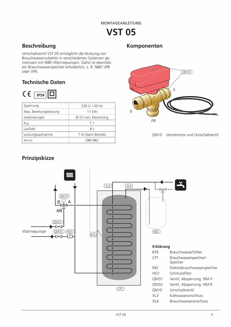
VST 05BeschreibungUmschaltventil VST 05 ermöglicht die Nutzung von Brauchwasserzubehör in verschiedenen Systemen gemeinsam mit NIBEWärmepumpen. Dafür ist ebenfalls ein Brauchwasserspeicher erforderlich, z. B. NIBE VPB oder VPA.
Technische Daten
Spannung 230 V, ~50 Hz
Max. Bereitungsleistung 11 kW
Verbindungen Ø 22 mm, Klemmring
Kvs 7.1
Laufzeit 8 s
Leistungsaufnahme 7 W (beim Betrieb)
Art.nr. 089 982
Prinzipskizze
IP54
AB
B A
QN10 Ventilmotor und Umschaltventil
Komponenten
LEK
ErklärungBT6 BrauchwasserfühlerCP1 Brauchwasserspeicher/
SpeicherEB2 ElektrobrauchwasserspeicherHQ1 SchmutzfilterQM31 Ventil, Absperrung, HMVQM32 Ventil, Absperrung, HMRQN10 UmschaltventilXL3 KaltwasseranschlussXL4 Brauchwasseranschluss
AB
B
QN10
A
Wärmepumpe
QN10
BT6
QM31
QM32 HQ1
XL3 XL4
EB2
CP1
5VST 05
GB

FunktionBei einem Brauchwasserbedarf wird der Ladevolumenstrom zum Brauchwasserspeicher mithilfe des Umschaltventils (QN10) geregelt. Ansonsten wird der Ladevolumenstrom zu den übrigen Teilen des Systems geleitet, z. B. zum Heizsystem.
MontageDas Umschaltventil (QN10) wird zwischen Wärmequelle und Brauchwasserspeicher/restlichem System montiert. In der Ausgangsstellung, ohne Steuerspannung, muss das Umschaltventil zum restlichen System geöffnet sein. Bei anliegender Steuerspannung wird das Umschaltventil zum Brauchwasserspeicher geöffnet.
Montage des Ventilmotors1. Befestigen Sie den Ventilmotor (A) mit der vormon
tierten Feder am Ventil. Siehe Abbildung unten.2. Drücken Sie den Ventilmotor nach unten, bis ein
Klicken ertönt. In diesem Fall ist der Motor zum Ventil hin gesperrt.
Demontage ■ Ziehen Sie die Feder (B) heraus und demontieren Sie
die Komponenten. Siehe Abbildung unten.
LEK
LEK
Elektrischer Anschluss
Der Ventilmotor wird gemäß dem folgenden Schema angeschlossen.
Weitere Informationen zu elektrischen Anschlüssen entnehmen Sie der jeweiligen Installations bzw. Montage und Wartungsanleitung für das System, mit dem das Umschaltventil verbunden werden soll.
Elektrische Installation sowie eventuelle
Servicearbeiten müssen unter Aufsicht
eines ausgebildeten Elektroinstallateurs
erfolgen. Unterbrechen Sie vor etwaigen
Servicearbeiten die Stromversorgung
per Betriebsschalter. Bei der elektrischen
Installation und beim Verlegen der
Leitungen sind die geltenden Vorschriften
zu berücksichtigen.
A
Hinweis:
B
NULL
L
Steuerungsphase
M 1 ~
Braun
Blau
Schwartz
6 VST 05
DE


PL
NL
FI
DK
DE
CZ
NIBE Energy Systems OY, Juurakkotie 3, 01510 Vantaa
3C Broom Business Park, Bridge Way, Chesterfield S41 9QG
Puh: 09-274 697 0 E-mail: [email protected] www.nibe.fi
FRAIT France, 10 rue des Moines, 67500 HaguenauTel : 03 88 06 24 10 Fax : 03 88 06 90 15 E-mail: [email protected] www.nibe.fr
NIBE-BIAWAR Sp. z o. o. Aleja Jana Pawła II 57, 15-703 BIAŁYSTOKTel: 085 662 84 90 Fax: 085 662 84 14 E-mail: [email protected] www.biawar.com.pl
RU © "EVAN" 17, per. Boynovskiy, Nizhny NovgorodTel./fax +7 831 419 57 06 E-mail: [email protected] www.nibe-evan.ru
NIBE Energietechniek B.V., Postbus 634, NL 4900 AP OosterhoutTel: 0168 477722 Fax: 0168 476998 E-mail: [email protected] www.nibenl.nl
Vølund Varmeteknik A/S, Member of the Nibe Group, Brogårdsvej 7, 6920 VidebækTel: 97 17 20 33 Fax: 97 17 29 33 E-mail: [email protected] www.volundvt.dk
NIBE Systemtechnik GmbH, Am Reiherpfahl 3, 29223 CelleTel: 05141/7546-0 Fax: 05141/7546-99 E-mail: [email protected] www.nibe.de
CHNIBE Wärmetechnik AG, Winterthurerstrasse 710, CH-8247 FlurlingenTel: (52) 647 00 30 Fax: (52) 647 00 31 E-mail: [email protected] www.nibe.ch
ATKNV Energietechnik GmbH, Gahberggasse 11, 4861 SchörflingTel: +43 (0)7662 8963-0 Fax: +43 (0)7662 8963-44 E-mail: [email protected] www.knv.at
NIBE AB Sweden, Box 14, Hannabadsvägen 5, SE-285 21 MarkarydTel: +46-(0)433-73 000 Fax: +46-(0)433-73 190 E-mail: [email protected] www.nibe.eu
GBNIBE Energy Systems Ltd,Tel: 0845 095 1200 Fax: 0845 095 1201 E-mail: [email protected] www.nibe.co.uk
NOABK AS , Brobekkveien 80, 0582 Oslo, Postadresse: Postboks 64 Vollebekk, 0516 OsloTel. sentralbord: +47 23 17 05 20 E-mail: [email protected] www.nibeenergysystems.no
Druzstevni zavody Drazice s.r.o, Drazice 69, CZ - 294 71 Benatky nad JizerouTel: +420 326 373 801 Fax: +420 326 373 803 E-mail: [email protected] www.nibe.cz
031586