secure installation and operation of your
TRANSCRIPT

Secure Installation and Operation of your Xerox® Alta Link® B8045 / B8055 / B8065 / B8075 / B8090
Multifunction Printer
Xerox® AltaLink® C8030 / C8035 / C8045 / C8055 / C8070 Color
Multifunction Printer
VERSION 1.8
JUNE 7, 2021
Sed ut perspiciatis unde omnis iste natus error sit voluptatem accusantium doloremque.
Month 00,
0000
<Part
Number>

Disclaimer
The information provided in this Xerox® Product Response is provided "as is" without warranty of any kind. Xerox
Corporation disclaims all warranties, either express or implied, including the warranties of merchantability and fitness for a
particular purpose. In no event shall Xerox Corporation be held responsible for any damages whatsoever resulting from
user's use or disregard of the information provided in this Xerox® Product Response including direct, indirect, incidental,
consequential, loss of business profits or special damages, even if Xerox Corporation has been advised of the possibility of
damages. Some states do not allow the exclusion or limitation of liability for consequential damages so the foregoing
limitation may not apply.
©2019 Xerox Corporation. All rights reserved. Xerox®, Xerox and Design® and AltaLink® are trademarks of Xerox
Corporation in the United States and/or other countries. BR22931
Other company trademarks are also acknowledged.
Document Version: 1.8 (June 2021).

1
Secure Installation and Operation of Your Xerox® AltaLink® B8045 / B8055 / B8065 / B8075 / B8090 Multifunction Printer and Xerox® AltaLink® C8030 / C8035 / C8045 / C8055 / C8070 Color Multifunction Printer
Purpose and Audience This document provides information on the secure installation, setup and operation. All customers, but particularly those concerned with secure installation and operation of these devices, should follow these guidelines.
Overview
This document lists some important customer information and guidelines1 that will ensure that your device is operated and maintained in a secure manner.
Background
These products are evaluated as part of Common Criteria certification in a particular configuration, referred to in the rest of this document as the “evaluated configuration”. Section I describes how to install and configure the machine so that it is in the same configuration as it is for evaluation.
Customers are advised that changes to the evaluated configuration may be required to support business goals and for compliance with policies applicable to their environment2. After careful review of this document, customers should document settings to be applied to devices in their environment establishing a unique benchmark configuration to support processes such as installation, change management and audit. Xerox Professional Services, which can be contacted via http://www.xerox.com/about-xerox/customer-training/tab1-ab-enus.html, can assist in evaluating and configuring these devices.
The information provided here is consistent with the security functional claims made in the applicable Security Targets3. When Common Criteria certification of these products is completed, the Security Targets will be available from the Common Criteria Certified Product website (http://www.commoncriteriaportal.org/products.html) list of evaluated products, from the Xerox security website (http://www.xerox.com/information-security/common-criteria-certified/enus.html), or from your Xerox representative.
It should be noted that throughout the rest of this document the terms “system administrator” or “administrator” are used to refer to the U.ADMIN role specified in the applicable Security Targets and in the Hardcopy Device Protection Profile4 while the terms “user” or “users” are used to refer to the U.NORMAL role in the Hardcopy Device Protection Profile.
I. Secure Installation and Set-up in the Evaluated Configuration
To set up the machines in the evaluated configuration, follow the guidelines below:
A. Set up and configure the following security protocols and functions in the evaluated configuration:
Immediate Image Overwrite
On Demand Image Overwrite
1 All guidelines in this document apply to the System Administrator unless explicitly stated otherwise. 2 For example, if the customer security policy requires that passwords are reset on a quarterly basis, the Reset Policy for the Admin Password will need to be enabled. Also, many customers choose to manage user credentials centrally, rather than on individual devices through local authorization. 3Xerox Multi-Function Device Security Target Xerox® AltaLink™ B8045 / B8055 / B8065 / B8075 / B8090, Version 1.0, Nov 2017; Xerox Multi-Function Device Security Target Xerox® AltaLink™ C8030 / C8035 / C8045 / C8055 / C8070, Version 1.0, Nov 2017 4 Protection Profile for Hardcopy Devices IPA, NIAP, and the MFP Technical Community, Version 1.0, September 10, 2015

2
FIPS 140-2 Mode
IP Filtering
Audit Log
Security Certificates, Transport Layer Security (TLS)/Secure Sockets Layer (SSL) and HTTPS
IPsec
Local, Remote or Smart Card Authentication
Local or Remote Authorization
User Permissions
Personalization
802.1x Device Authentication
Session Inactivity Timeout
USB Port Security
SFTP Filing (only for transfer of the audit log to an audit log server)
Embedded Fax Secure Receive
Secure Print
Hold All Jobs
McAfee® Embedded Control
Erase Customer Data
System Administrator authentication is required when accessing the security features and
administrative functions of the device or when implementing the guidelines and recommendations
specified in this document. To log in as an authenticated System Administrator via the Embedded
Web Server (EWS)5, follow the instructions under “Accessing CentreWare Information Services as a
System Administrator” under “Accessing Administration and Configuration Settings” in Section 2 of
the applicable System Administration Guide (SAG)6.
To log in as an authenticated System Administrator via the Local User Interface (denoted hereafter
in this document as the Control Panel), follow “Accessing the Control Panel as a System
Administrator” under “Accessing Administration and Configuration Settings” in Section 2 of the SAG.
To log in as an authenticated user who is not the System Administrator ‘admin’ user, follow the
instructions for “Accessing CentreWare Information Services as a System Administrator” under
“Accessing Administration and Configuration Settings” in Section 2 of the applicable System
Administration Guide (SAG), except that instead of entering ‘admin’ for the User ID and the system
administrator password the user should enter his/her User ID and his/her authentication password.
B. Follow the instructions located in Chapter 4, Security, in the SAG to set up the security functions
listed in Item a above. Note that whenever the SAG requires that the System Administrator
provide an IPv4 address, IPv6 address or port number7 the values should be those that pertain to
the particular device being configured.
In setting up the device to be in the evaluated configuration, perform the following8:
5 The remote interface is referred to in documentation as the either the Embedded Web Server (EWS) or CenterWare Internet Services (CWIS). In this document it will be referred to as the EWS. 6Xerox® AltaLink® Series Multifunction Printers System Administrator Guide, Version 1.0, May 2017 7 The standard ports used on these devices are shown in Attachment 3. 8 The instructions for setting up the device in the Evaluated Configuration assume that the System Administrator has been successfully authenticated as a System Administrator at either the Control Panel or EWS following the instructions in section I.a of this document.

3
1. Authentication Passwords:
Authentication passwords for unique user accounts established for all users and System
Administrators should be set by the System Administrator to a minimum length of 8
alphanumeric characters unless applicable internal procedures the System Administrator
must comply with require a minimum password of a greater length (the minimum length can
be set to any value between 1 and 63 alphanumeric characters). Authentication passwords
should always be strong passwords by using a combination of upper case and lower case
letters, digits, and allowable special characters (“!”, “@”, “#”, “$”, “%”, “^”, “&”, “*”, “(“, “)”, and
other printable ISO 8859-15 set and Unicode/UTF-8 set characters except “>”), not use
common names or phrases, etc.
The ‘maximum length’ can be set to any value between 8 and 63 (alphanumeric) characters
consistent with the same internal procedures. Follow the instructions for “Specifying
Password Requirements” under “User Database” under “Configuring Authentication Settings”
in Section 4 of the SAG to set both the minimum and maximum user authentication password
lengths from the EWS.
2. Administrator Password:
i. Change the Administrator password upon installation. Reset the Administrator password
periodically. Change the Administrator password once a month. To change the
Administrator password from the EWS, follow the instructions under “Changing the
System Administrator Password” in Section 2 of the SAG.
To change the Administrator password from the Control Panel, follow the instructions
under “Changing the System Administrator Password at the Control Panel” in Section 2 of
the SAG.
ii. Disable the Admin Password Reset security feature so it is not used. To disable this
feature from the EWS, follow the instructions under “Disabling the Security Administrator
Password Reset” in Section 4 of the SAG.
3. Establishing A Remote Session:
To establish a remote session with the device via EWS, any user (whether a System Administrator or not) must perform the following:
a. Locate your device IP address using the Configuration Report. Note: The device prints a Configuration Report at power-up. Otherwise, you can print a Configuration Report by performing the following:
i. Touch Device, then touch Information Pages. ii. Touch Configuration Report, then touch Print.
Ensure that TCP/IP and HTTP are enabled. If you disabled either of the protocols, at the Control Panel, re-enable the protocols.
b. At your computer, open a Web browser. In the address field, type the IP address of the device, then press Enter or Return.
Note: To ensure that untrusted-certificate Web browser errors do not appear, install the Device Root Certificate Authority for the device (see B.8 below).
c. In the top right area of the page, click Login.
d. Type in the user’s User ID and password in the appropriate field.
e. Click Log

4
4. Authentication:
i. Establish local authentication at the device via either the Control Panel or EWS by following the “Configuring Local Authentication Settings” instructions in Section 4 of the SAG.
Set up unique user accounts with appropriate credentials (user names and passwords) on
the device for all users who require access to the device via the Control Panel or EWS by
following the “User Database” instructions in Section 4 of the SAG.
ii. Configure network (remote) authentication access to network accounts from either the Control Panel or EWS by performing the following:
Configuring Network Authentication Settings To configure access rights using network authentication: • Set the login method to User Name / Password - Validate on the Network. To set
the Login Method for the EWS perform the following: 1. In the Embedded Web Server, click
Properties→Login/Permissions/Accounting.
2. Click Login Methods.
3. For Control Panel & Website Login Methods, click Edit.
4. For Website Login, select an option. Note: Website Login is only available when the following authentication method is enabled for the control panel: • Smart Cards
5. Click Save.
In the evaluated configuration, the only allowable Authentication Type is LDAP.
Configuring Authentication Server Settings for LDAP on the EWS
The device uses an LDAP server for authentication, authorization, and personalization. The LDAP server appears in the EWS on the LDAP Server page.
Select LDAP as the network authentication method and authorization method. The device will use this server automatically
1. On the Login Methods page, for Authentication Servers, click Edit. 2. For Authentication Type, select LDAP. 3. Click Add New. 4. Configure LDAP server settings, then click Apply. 5. Enable SSL 6. Select ‘Enable Secure Connection (LDAPS)
To Configuring a Secure LDAP Connection:
1. In the EWS, click Properties→Connectivity→Setup.
2. In the Protocol area, for LDAP, click Edit.
3. On the LDAP page, click Add New.
4. To enable a secure connection to the LDAP server, for Secure LDAP Connection, select Enable
5. To validate the SSL certificate used for HTTPS, select Validate Server Certificate (trusted, not expired, correct FQDN).

5
6. To view a list of external root or intermediate trusted SSL certificates, click View Root/ Intermediate Trusted Certificates.
7. For Root/Intermediate Trusted Certificates, select a certificate.
8. To view the selected certificate details, or to save the certificate to your computer, click View/Save.
Note: If the LDAP Server has encryption enabled, ensure that a certificate issued from the
LDAP server certificate authority is installed on the device.
iii. Establish user authentication via a Smart Card and smart card reader by following the “Configuring Smart Card Authentication Settings” instructions in Section 4 of the SAG. Note that smart card authentication is done at the device and may require inputs at the Control Panel.
Note that there are two other authentication methods available on the device – Xerox Secure
Access and Convenience Authentication. Neither of these two authentication methods is
allowable as part of the evaluated configuration. Note also that proximity cards are only
supported by Xerox Secure Access and Convenience Authentication, so proximity cards are
also not part of the evaluated configuration.
5. Authorization:
Either local authorization or network authorization using LDAP is allowed in the evaluated configuration.
Local Authorization
i. Establish local authorization at the device using the Control Panel by following the “Configuring Local Authorization Settings” instructions in Section 4 of the SAG. Note that local user accounts on the device should be set up first before user permissions are set up.
When adding new users, set up user roles and user permissions to access device apps and pathways based on the roles users are assigned to by following the instructions for “User Permissions” under “Configuring Authentication Settings” in Section 4 of the SAG. Follow these same instructions to add/delete user role, to change the roles users are assigned to or to change what access permissions each role has.
ii. Set the permission for all Non-Logged In Users Roles via EWS (see “User Roles” in Section 4 of the SAG) to be Not Allowed for the following: (1) all print permission categories (by following the “Editing Print Permissions for the Non-Logged In Users Role” under “Configuring Authorization Settings” in Section 4 of the SAG) and (2) all apps/services and tools (by following the “Editing Apps and Tools Permissions for the Non-Logged In Users Role” under “Configuring Authorization Settings” in Section 4 of the SAG).
Network Authorization
i. Establish remote authorization via EWS using LDAP by following the “Configuring Network Authorization Settings” and “Configuring Network Authorization Server Settings” instructions in Section 4 of the SAG. Make sure to only follow the instructions pertaining to setting up an LDAP Server.
Network Authorization using an SMB server is not part of the evaluated configuration and should not be used.
Ensure that Logged-In Users have access (i.e., permission is Allowed) to the following apps (see “Editing Apps and Tools Permissions for the Non-Logged In Users Role” under “Configuring Authorization Settings” in Section 4 of the SAG):
Print From

6
Fax
Workflow Scanning
6. Personalization:
Enable personalization via EWS by following the instructions for “Specifying the Method the Printer Uses to Acquire Email Address of Users” under “Configuring Smart Card Authentication Settings” under “Configuring Authentication Settings” in Section 4 of the SAG. Configure personalization by following the instructions for “Configuring LDAP User Mappings” under “LDAP” in Section 3 of the SAG.
7. Immediate Image Overwrite:
Follow the instructions under ‘Enabling Immediate Image Overwrite at the Control Panel’ or ‘Enabling Immediate Image Overwrite’ in Section 4 of the SAG to enable Immediate Image Overwrite from the Control Panel or the EWS, respectively.
Both Immediate Image Overwrite and On Demand Image Overwrite are enabled by default at the factory when the device is first delivered.
8. Security Certificates:
Install a digital certificate on the device before enabling SSL via EWS by following the appropriate instructions under “Security Certificates” in in Section 4 of the SAG for installing any one of the digital certificates (Device Certificate, CA Certificate or Trusted Certificate) the device supports.
Note that a Xerox self-signed certificate is installed by default on the device. If a CA certificate is desired a Certificate Signing Request (CSR) will have to be sent to a Certificate Authority to obtain the CA Certificate before it can be installed on the device; follow the instructions for “Creating a Certificate Signing Request” under “Security Certificates” in in Section 4 of the SAG to create the CSR.
Note that in FIPS Mode (see I.b.9) SHA256 hashing/ 2048 bit key length / AES256 encryption will automatically be the default signing method used for the creation of the auto-generated Default Xerox Device Certificate, all re-created Default Xerox Device Certificates and any device generated CSRs.
Note that if a New Xerox Device Certificate is installed on the device, the friendly name automatically assigned by the device for that certificate may not be correct.
9. Transport Layer Security (TLS)/Secure Sockets Layer (SSL):
i. The following TLS cipher suites are supported in the evaluated configuration:
TLS_RSA_WITH_AES_128_CBC_SHA
TLS_RSA_WITH_AES_256_CBC_SHA
TLS_DHE_RSA_WITH_AES_128_CBC_SHA
TLS_DHE_RSA_WITH_AES_256_CBC_SHA
TLS_RSA_WITH_AES_128_CBC_SHA256
TLS_RSA_WITH_AES_256_CBC_ SHA256
TLS_DHE_RSA_WITH_AES_128_CBC_ SHA256
TLS_DHE_RSA_WITH_AES_256_CBC_ SHA256
TLS_ECDHE_ECDSA_WITH_AES_128_GCM_SHA256
TLS_ECDHE_ECDSA_WITH_AES_256_GCM_SHA384 TLS_ECDHE_ECDSA_WITH_AES_128_CBC_SHA256
TLS_ECDHE_ECDSA_WITH_AES_256_CBC_SHA384
TLS_ECDHE_RSA_WITH_AES_128_GCM_SHA256
TLS_ECDHE_RSA_WITH_AES_256_GCM_SHA384
TLS_ECDHE_RSA_WITH_AES_128_CBC_SHA256
7
TLS_ECDHE_RSA_WITH_AES_256_CBC_SHA384
TLS_ECDHE_RSA_WITH_AES_128_CBC_SHA
TLS_ECDHE_RSA_WITH_AES_256_CBC_SHA
TLS_ECDHE_ECDSA_WITH_AES_128_CBC_SHA
TLS_ECDHE_ECDSA_WITH_AES_256_CBC_SHA
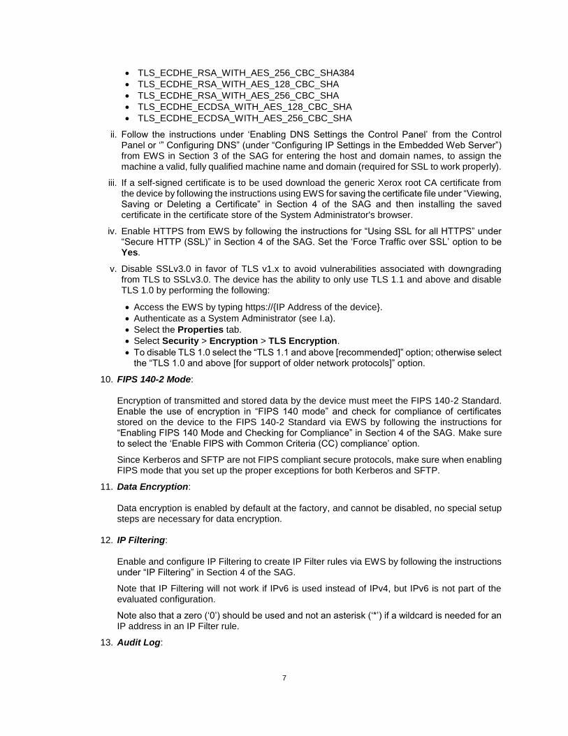
ii. Follow the instructions under ‘Enabling DNS Settings the Control Panel’ from the Control Panel or ‘” Configuring DNS” (under “Configuring IP Settings in the Embedded Web Server”) from EWS in Section 3 of the SAG for entering the host and domain names, to assign the machine a valid, fully qualified machine name and domain (required for SSL to work properly).
iii. If a self-signed certificate is to be used download the generic Xerox root CA certificate from the device by following the instructions using EWS for saving the certificate file under “Viewing, Saving or Deleting a Certificate” in Section 4 of the SAG and then installing the saved certificate in the certificate store of the System Administrator's browser.
iv. Enable HTTPS from EWS by following the instructions for “Using SSL for all HTTPS” under “Secure HTTP (SSL)” in Section 4 of the SAG. Set the ‘Force Traffic over SSL’ option to be Yes.
v. Disable SSLv3.0 in favor of TLS v1.x to avoid vulnerabilities associated with downgrading from TLS to SSLv3.0. The device has the ability to only use TLS 1.1 and above and disable TLS 1.0 by performing the following:
Access the EWS by typing https://{IP Address of the device}.
Authenticate as a System Administrator (see I.a).
Select the Properties tab.
Select Security > Encryption > TLS Encryption.
To disable TLS 1.0 select the “TLS 1.1 and above [recommended]” option; otherwise select the “TLS 1.0 and above [for support of older network protocols]” option.
10. FIPS 140-2 Mode:
Encryption of transmitted and stored data by the device must meet the FIPS 140-2 Standard. Enable the use of encryption in “FIPS 140 mode” and check for compliance of certificates stored on the device to the FIPS 140-2 Standard via EWS by following the instructions for “Enabling FIPS 140 Mode and Checking for Compliance” in Section 4 of the SAG. Make sure to select the ‘Enable FIPS with Common Criteria (CC) compliance’ option.
Since Kerberos and SFTP are not FIPS compliant secure protocols, make sure when enabling FIPS mode that you set up the proper exceptions for both Kerberos and SFTP.
11. Data Encryption:
Data encryption is enabled by default at the factory, and cannot be disabled, no special setup steps are necessary for data encryption.
12. IP Filtering:
Enable and configure IP Filtering to create IP Filter rules via EWS by following the instructions under “IP Filtering” in Section 4 of the SAG.
Note that IP Filtering will not work if IPv6 is used instead of IPv4, but IPv6 is not part of the evaluated configuration.
Note also that a zero (‘0’) should be used and not an asterisk (‘*’) if a wildcard is needed for an IP address in an IP Filter rule.
13. Audit Log:

8
The Audit Log consists of two components – the main audit log and a set of protocol log files (one for each of the four secure protocols – TLS, HTTPS, SSH which SFTP uses and IPsec). The main audit log contains the audit log elements that one would typically find in an audit log; the contents of the main audit log are contained in the Security Guide for each product covered in these guidelines; the Security Guide can be located by searching for the specific device on the Xerox Security Web Site www.xerox.com/security. Attachment 1 to this document provides selected audit log entries that pertain to the security functions/features discussed in this document. Attachment 2 lists what specific audit log entries are associated with each required audit log element in Table 9 of the applicable Security Targets.
For each audit log entry in the main audit log a time stamp is included.
The set of multiple protocol log files contain log information pertaining to secure sessions. Specifically, the protocol log files each contain:
A date/time stamp for each entry
The remote IP address of the endpoint of the communication session.
The protocol used for the secure session.
A status indicating that the secure session was successful or a failure.
An error indicator (error code or message) indicating the reason for the error - this is the reason for session failure. Note: The specific message or code is an outcome of the various logging technologies used in the system.
The protocol log files are enabled separately from the main audit log by performing the following:
Access the EWS by typing https://{IP Address of the device}.
Authenticate as a System Administrator (see I.a).
Select the Properties tab.
Select Security > Audit Log.
Select the Enabled checkbox under ‘Protocol Log’
Click Apply.
Enable the audit log, download the audit log .csv file and then store it in a compressed file on an external IT product using the EWS by following the appropriate instructions for “Enabling Audit Log” and “Saving an Audit Log”, respectively, under “Audit Log” in Section 4 of the SAG. Note that the downloaded file will contain in separate files both the main audit log and the four protocol log files.
In downloading or transferring the main Audit Log and log files to a drive or other external trusted IT product, the System Administrator should ensure that Audit Log records are protected after they have been exported to an external trusted IT product and that the exported records are only accessible by authorized individuals.
The actual format of the Audit Log, including time stamps, is indicated in “Interpreting the Audit Log” under “Audit Log” in Section 4 of the SAG.
The System Administrator should download and review the main Audit Log and protocol log files on a daily basis.
The main Audit Log can contain up to 15,000 entries. Once the Audit Log is full it will overwrite the oldest event with the new event information, and it will keep logging events this way until the main Audit Log is cleared. The machine will send a warning email when the audit log is filled to 90% (i.e., 13,500) of the 15,000 maximum allowable number of entries and repeated thereafter at 15,000 entries until the Audit Log is downloaded.
The protocol log files can hold up to 10MB worth of data. Just as was the case for the main Audit Log, once a Protocol Log File is full it will overwrite the oldest entries with the new information, and it will keep logging entries this way until the Audit Log is cleared. The machine will send a warning email when a protocol log file is filled to 90% of maximum capacity and repeated each time it reaches 90% capacity until the Audit Log is downloaded.

9
The System Administrator should be aware that there is the possibility that on an intermittent basis multiple entries may be included in the audit log for the same event.
The Audit Log can be transferred to an audit log server outside the device by following the directions for “Enabling Automatic Log Transfer” under “Audit Log” in Section 4 of the SAG. The only special requirement on the audit log server the Audit Log is to be transferred to is that it must support the SFTP protocol. As was the case for downloading the audit log, when you transfer the audit log you will get both the main audit log and the four protocol log files.
14. IPsec: Enable and configure IPsec using the EWS by following the instructions under “IPsec” in Section 4 of the SAG. Note that IPsec should be used to secure printing jobs; HTTPS (SSL) should be used to secure scanning jobs. Use the default values for IPsec parameters whenever possible for secure IPsec setup.
To encrypt (PROTECT) a protocol via IPsec, create a security policy9 as follows:
Follow the instructions under “Managing Host Groups” to create a new host group or use a predefined Host Group.
Follow the instructions under “Managing Protocol Groups” to create a Protocol Group that includes the protocol(s) that you want to encrypt using IPsec.
Follow the instructions under “Managing Actions” to create an IPsec action with the desired parameters.
Create a security policy by selecting the Security Policies tab and following the instructions
for “Managing Security Policies”. Make sure to select the Host Group and Protocol Group just created and select the action of ‘Block’. Click Add Policy to add this new security policy.
Now create a second security policy with the default values for Host Group (‘All’) and Protocol Group (‘All’) and an action of ‘Pass’ – that will cause all protocols created to not be encrypted (BYPASS), except for in this case the protocols covered by the first rule created that are to be protected and IPsec will encrypt the packets transmitted over the protected protocol.
Make sure that the security policy that blocks the protocols for which encryption is desired is the top priority policy (if it is not already) by performing the following:
o Under Saved Policies, select the policy you want to move, then click the Promote or Demote buttons.
By default, any packet that does not fit any user defined security policy will be dropped (DISCARD). Therefore, if the second security policy was not created in the above case, for example, any packet that was not for one of the protocols that was to be encrypted would automatically be discarded.
The instructions for “Creating a New Action” under “Managing Actions” under “IPsec” in Section 4 of the SAG describe how to set up an IPsec action to use either tunnel or transport mode.
The instructions for “Configuring Internet Key Exchange Settings” describe how to set the key lifetimes for IKE Phase 1 and Phase 2, the DH Group, the hash algorithm and the encryption algorithm. Note the that maximum key lifetime for both Phase 1 and Phase 2 is 86,400 seconds (24 hours), which is the default value, and the minimum key lifetime is 60 seconds for Phase 1 and 300 seconds for Phase 2.
The device only supports the following for IPsec – IKEv1 protocol with main mode and DH Groups 2 (1024-bit MODP) and 14 (2048-bit MODP).
9 Note that IPsec security policies are sets of conditions, configuration options, and security settings that enable two systems to agree on how to secure traffic between them. You can have multiple policies active at the same time, however, the scope and policy list order determine the overall policy behavior.
10
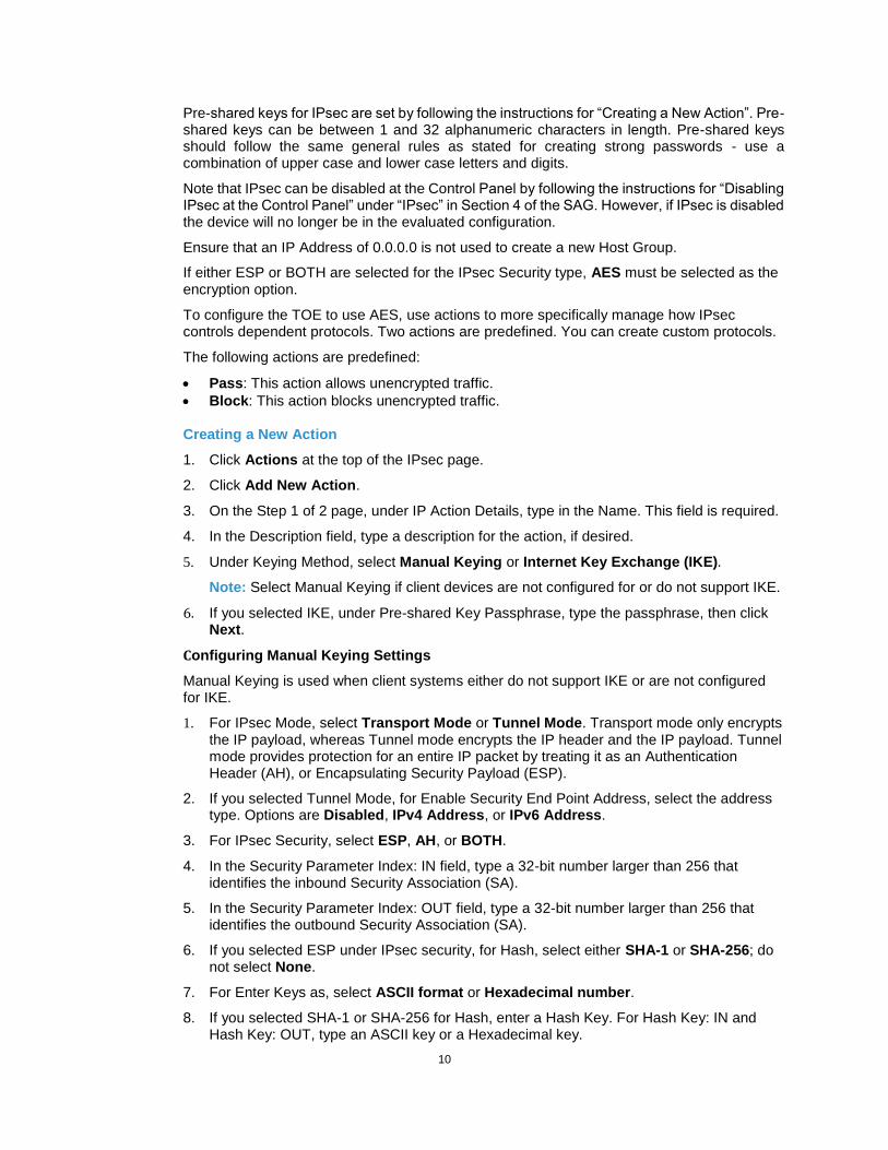
Pre-shared keys for IPsec are set by following the instructions for “Creating a New Action”. Pre-shared keys can be between 1 and 32 alphanumeric characters in length. Pre-shared keys should follow the same general rules as stated for creating strong passwords - use a combination of upper case and lower case letters and digits.
Note that IPsec can be disabled at the Control Panel by following the instructions for “Disabling IPsec at the Control Panel” under “IPsec” in Section 4 of the SAG. However, if IPsec is disabled the device will no longer be in the evaluated configuration.
Ensure that an IP Address of 0.0.0.0 is not used to create a new Host Group.
If either ESP or BOTH are selected for the IPsec Security type, AES must be selected as the encryption option.
To configure the TOE to use AES, use actions to more specifically manage how IPsec controls dependent protocols. Two actions are predefined. You can create custom protocols.
The following actions are predefined:
Pass: This action allows unencrypted traffic.
Block: This action blocks unencrypted traffic.
Creating a New Action
1. Click Actions at the top of the IPsec page.
2. Click Add New Action.
3. On the Step 1 of 2 page, under IP Action Details, type in the Name. This field is required.
4. In the Description field, type a description for the action, if desired.
5. Under Keying Method, select Manual Keying or Internet Key Exchange (IKE).
Note: Select Manual Keying if client devices are not configured for or do not support IKE.
6. If you selected IKE, under Pre-shared Key Passphrase, type the passphrase, then click Next.
Configuring Manual Keying Settings
Manual Keying is used when client systems either do not support IKE or are not configured for IKE.
1. For IPsec Mode, select Transport Mode or Tunnel Mode. Transport mode only encrypts the IP payload, whereas Tunnel mode encrypts the IP header and the IP payload. Tunnel mode provides protection for an entire IP packet by treating it as an Authentication Header (AH), or Encapsulating Security Payload (ESP).
2. If you selected Tunnel Mode, for Enable Security End Point Address, select the address type. Options are Disabled, IPv4 Address, or IPv6 Address.
3. For IPsec Security, select ESP, AH, or BOTH.
4. In the Security Parameter Index: IN field, type a 32-bit number larger than 256 that identifies the inbound Security Association (SA).
5. In the Security Parameter Index: OUT field, type a 32-bit number larger than 256 that identifies the outbound Security Association (SA).
6. If you selected ESP under IPsec security, for Hash, select either SHA-1 or SHA-256; do not select None.
7. For Enter Keys as, select ASCII format or Hexadecimal number.
8. If you selected SHA-1 or SHA-256 for Hash, enter a Hash Key. For Hash Key: IN and Hash Key: OUT, type an ASCII key or a Hexadecimal key.
11
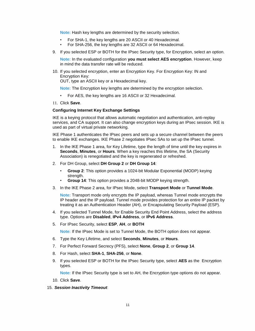
Note: Hash key lengths are determined by the security selection.
• For SHA-1, the key lengths are 20 ASCII or 40 Hexadecimal. • For SHA-256, the key lengths are 32 ASCII or 64 Hexadecimal.
9. If you selected ESP or BOTH for the IPsec Security type, for Encryption, select an option.
Note: In the evaluated configuration you must select AES encryption. However, keep in mind the data transfer rate will be reduced.
10. If you selected encryption, enter an Encryption Key. For Encryption Key: IN and Encryption Key: OUT, type an ASCII key or a Hexadecimal key.
Note: The Encryption key lengths are determined by the encryption selection.
• For AES, the key lengths are 16 ASCII or 32 Hexadecimal.
11. Click Save.
Configuring Internet Key Exchange Settings
IKE is a keying protocol that allows automatic negotiation and authentication, anti-replay services, and CA support. It can also change encryption keys during an IPsec session. IKE is used as part of virtual private networking.
IKE Phase 1 authenticates the IPsec peers and sets up a secure channel between the peers to enable IKE exchanges. IKE Phase 2 negotiates IPsec SAs to set up the IPsec tunnel.
1. In the IKE Phase 1 area, for Key Lifetime, type the length of time until the key expires in Seconds, Minutes, or Hours. When a key reaches this lifetime, the SA (Security Association) is renegotiated and the key is regenerated or refreshed.
2. For DH Group, select DH Group 2 or DH Group 14:
• Group 2: This option provides a 1024-bit Modular Exponential (MODP) keying strength.
• Group 14: This option provides a 2048-bit MODP keying strength.
3. In the IKE Phase 2 area, for IPsec Mode, select Transport Mode or Tunnel Mode.
Note: Transport mode only encrypts the IP payload, whereas Tunnel mode encrypts the IP header and the IP payload. Tunnel mode provides protection for an entire IP packet by treating it as an Authentication Header (AH), or Encapsulating Security Payload (ESP).
4. If you selected Tunnel Mode, for Enable Security End Point Address, select the address type. Options are Disabled, IPv4 Address, or IPv6 Address.
5. For IPsec Security, select ESP, AH, or BOTH
Note: If the IPsec Mode is set to Tunnel Mode, the BOTH option does not appear.
6. Type the Key Lifetime, and select Seconds, Minutes, or Hours.
7. For Perfect Forward Secrecy (PFS), select None, Group 2, or Group 14.
8. For Hash, select SHA-1, SHA-256, or None.
9. If you selected ESP or BOTH for the IPsec Security type, select AES as the Encryption types.
Note: If the IPsec Security type is set to AH, the Encryption type options do not appear.
10. Click Save.
15. Session Inactivity Timeout:

12
Enable the session inactivity timers (termination of an inactive session) from the EWS by following the instructions for “Setting System Timeout Values” or from the Control Panel by following the instructions for “Setting the System Timeout Values at the Control Panel” in Section 4 of the SAG.
The default session timeout limits are 60 seconds for the Control Panel and 60 minutes for the EWS. To avoid unexpected false error messages make sure the EWS session inactivity timer is less than 25 days.
16. Secure Print: Set the Secure Print security function to require the User ID for identification purposes to release a secure print job. Access and configure the Secure Print security function using the EWS by following the instructions under “Configuring Secure Print Settings” in Section 5 of the SAG.
Ensure that the ‘Release Policies for Secure Print Jobs Requiring Passcode When the User is Already Logged In’ option is set to Prompt for Passcode Before Releasing Jobs.
For best security, print jobs (other than LANFax jobs) submitted to the device from a client or from the EWS should be submitted as a secure print job. To ensure that print jobs can only be submitted as secure print jobs, for logged in users (since non-logged in users are denied permission to print any job in the evaluated configuration) follow the instructions for “Setting Job Type Print Permissions under “Editing Print Permissions for the Non-Logged In Users Role” under “Configuring Authorization Settings” in Section 4 of the SAG, select Custom and then set the permission to be Allowed for Secure Print and Not Allowed for all other print types.
Once a secure print job has been submitted the authenticated user can either release the job for printing at the Control Panel by following the instructions under ”Secure Print” under “Printing Features” in Section 6 (Print) of the applicable User Guide10 or delete the job at the Control Panel by following the directions under “Viewing, Printing or Deleting Jobs” under “Managing Secure and Held Print Jobs” under “Jobs” in Section 5 of the applicable User Guide.
Note that only the submitter of a secure print job can release the job, and in the evaluated configuration only the System Administrator can delete any job, except for a secure print job where the job submitter can delete the job by entering the secure print PIN. To ensure that only the System Administrator can delete jobs, perform the following based on the instructions for “Editing a Logged-In User Role” and under “Editing Apps and Tools Permissions for the Non-Logged-In Users Role” under “Configuring Authorization Settings” in Section 4 of the SAG:
Create a new permission role for Logged-In Users and give it any desired descriptive name.
For this newly created role, set the method to be All Logged-In Users.
Under the Apps & Tools tab, choose Custom. When the page is refreshed, go to the selection under ‘Jobs’ for ‘Job Deletion (Active Queue Only)’ and set it to Not Allowed.
Click Apply to save the changes.
17. Hold All Jobs:
The Hold All Jobs function is used in the evaluated configuration. Set the Enablement option to Hold All Jobs in a Private Queue and the Unidentified Jobs Policies option to Hold Jobs; Only Administrators can Manage Jobs using the EWS by following the instructions for “Configuring the Hold All Jobs Feature” under “Hold All Jobs” in Section 5 of the SAG.
10Xerox® AltaLink™ B80XX Series Multifunction Printer Multifunction Printer User Guide, Version 1.0, May
2017; Xerox® C80XX Series Multifunction Printer Multifunction Printer User Guide Version 1.0, May 2017.

13
Once a held print job has been submitted the authenticated user can either release the job for printing at the Control Panel by following the instructions under ”Releasing Held Print Jobs” under “Held Print Jobs” under “Printing Features” in Section 5 of the applicable User Guide. To delete a held job at the Control Panel follow the applicable instructions under “Managing Jobs at the Control Panel” under “Managing Jobs” in Section 5 of the applicable User Guide.
As is the case for a secure print job only the submitter of a held print job can release the job, and only the System Administrator can delete any print job.
18. 802.1x Device Authentication:
Enable and configure 802.1x device authentication from the Control Panel by following the instructions for “Enabling and Configuring 802.1x at the Control Panel” or from the EWS by following the instructions for “Enabling and Configuring 802.1x in the Embedded Web Server” in Section 4 of the SAG. Ensure that the 802.1x username and password are not blank when configuring 802.1x device authentication from the Control Panel.
Note: To be in the evaluated configuration EAP-TLS should be selected as the 802.1x authentication method.
19. USB Port Security:
In the evaluated configuration USB ports should all be disabled, If an USB port needs to be used to perform a function like diagnostics or installing a software upgrade, the applicable host or target USB port should be temporarily enabled while the applicable function is being performed, and then when the function is competed it should be immediately disabled again. Enable or disable the USB Ports using the EWS by following the instructions for “Enabling and Disabling USB Ports” under “USB Port Security” in Section 4 of the SAG. To enable or disable the USB Ports using the Control Panel follow the instructions for “Enabling or Disabling All USB Ports at the Control Panel” under “USB Port Security” in Section 4 of the SAG.
20. SFTP Filing:
SFTP Filing is used in the evaluated configuration only for transfer of the Audit Log to an external audit log server. Specify the use of Secure FTP for transferring the Audit Log to an external audit log server using the EWS by following the instructions for “Configuring FTP and SFTP Filing Settings” under “FTP/SFTP Filing” in Section 3 of the SAG.
Note that for SFTP the underlying SSH encryption algorithms, which SFTP uses, cannot be configured.
21. McAfee® Embedded Control:
If use of the Embedded Device Security is desired, from the EWS check that Embedded Device Security is enabled by following the instructions under “McAfee Embedded Control” in Section 4 of the SAG. If Enhanced Security is desired, select the Enhanced Security for the ‘Security Level’; if the ‘Integrity Control’ option is desired, select Integrity Control for the ‘Security Level’. Do not select the Disable McAfee Secure Device ‘Security Level’ option. Note that Enhanced Security is the default option.
Since Integrity Control is a purchasable option, before the Security Level can be set to Integrity Control this option must first be installed on the device; enter the installation key for the Integrity Control option provided by Xerox when the option is purchased in the appropriate step in the instructions under “McAfee Embedded Control” in Section 4 of the SAG.
To install Integrity Control from the Control Panel perform the following:

14
Press the Machine Status button and then the Tools tab.
Touch Device Settings > General.
Touch Feature Installation.
Enter the installation key for the Integrity Control option provided by Xerox when the option is purchased in the ‘Enter Feature Installation Key’ text box.
Touch OK.
22. Erase Customer Data:
Initiate the feature to erase all customer date from the device at the Control Panel by following the instructions for “Erase Customer Data” in Section 10 of the SAG.
C. The following protocols, services and functions are considered part of the evaluated configuration and should be enabled when needed:
TCP/IP
Date and Time
Copy
Embedded Fax
Fax Forwarding on Receive (for received Embedded Faxes)
Scan to E-mail, including email encryption and signing
Workflow Scanning
Scan to Mailbox
Print from Mailbox
NTP
When setting up the device to be in the evaluated configuration, perform the following special setup for the above services (otherwise follow the appropriate instructions in the appropriate section of the SAG to set up and/or configure the protocol/service/function):
1. TCP/IP:
Enable IPv4 and IPv6 from the Control Panel by following the instructions for “Enabling TCP/IP” under “IP” in Section 3 of the SAG. Configure IPv4 or IPv6 by following the instructions for “Configuring TCP/IP Settings at the Control Panel” under “IP” in Section 3 of the SAG.
Set up and configure IPv4 and IPv6 from the EWS by following the instructions for “Configuring IPv4” and “Configuring IPv6”, respectively, under “Configuring IP Settings in the Embedded Web Server” under “IP” in Section 3 of the SAG.
2. Date and Time:
Ensure that the date and time on the device is correct and is set for the correct time zone where the device is located. Set the date and time from the Control Panel by following the instructions in “Setting the Date and Time at the Control Panel” in Section 1 of the SAG.
Set the date and time from the EWS by following the instructions in “Setting the Date and Time in CentreWare Internet Services” in Section 1 of the SAG.
The ‘Date and Time Setup’ option can be set to either Manual (NTP Disabled) or Automatic Using NTP (see 1.c.7).

15
3. Embedded Fax:
Ensure that Embedded Fax is properly installed. The procedure for sending an Embedded Fax at the Control Panel and the features and settings available to a user for configuring/sending an Embedded Fax at the Control Panel are described under “Fax Workflows” under Fax in Section 5 (Xerox Apps) of the User Guide.
Set Embedded Fax parameters and options on the device at the Control Panel by following the instructions for “Configuring Required Fax Settings at the Control Panel“ under “Fax” in Section 8 of the SAG.
Set the minimum length of the (Embedded Fax) secure receive passcode from either the Control Panel or EWS by following the instructions in “Configuring Fax Passcode Length” under “Fax Security” in Section 8 of the SAG.
Enable and set (Embedded Fax) Secure Receive passcode from the Control Panel by performing the instructions for “Enabling or Disabling the Secure Fax Feature” under “Setting Incoming Fax Defaults” under “Embedded Fax” in Section 8 of the SAG. Set ‘Guest Access’ to Disabled to prevent unauthenticated users from being able to enable or disable Secure Receive.
Enable Fax Forwarding on Receive and establish up to five fax forward rules using the EWS by following the instructions for “Fax Forwarding” under “Fax” in Section 8 of the SAG. Only add E-mail addresses to the fax forward rules established by following the instructions for “Adding an Email Address to the Rule”.
Printing of Embedded Fax confirmation reports is not included in the evaluation. The Embedded Fax cover sheets should not be printed with an Embedded Fax job.
Be aware that if the Embedded Fax secure receive passcode length is changed via the control Panel, the changed secure receive passcode length may not be reflected on the Local User Interface after the system has saved the change. After the system has saved the change the changed secure receive passcode length will be reflected on the EWS and will be in effect when attempting to enter a new Embedded Fax secure receive passcode.
4. Scan To Mailbox:
Enable and configure the Scan to Mailbox feature from the EWS by following the instructions under ‘Enabling or Disabling Scan to Mailbox’ in Section 7 of the SAG.
Establish a unique Scan-to-Mailbox mailbox for each authenticated user.
Establish unique names for each Scan-to-Mailbox mailbox.
Be aware that if Scan-to-Mailbox folders are cloned any existing mailboxes on the target device that have the same name as a mailbox in the clone file will have their passwords reset to the password in the clone file.
Sometimes an existing Scan-to-Mailbox mailbox passcode may have to be entered twice to access the applicable mailbox.
In configuring the Scan to Mailbox feature, set the feature so that scanned documents are only stored in private folders and that public folders are not allowed by setting the proper scan policies. To set the scan policies for the Scan to Mailbox feature using the EWS follow the instructions under “Setting Scan Policies” in Section 7 of the SAG. in the evaluated configuration. Set the scan policies as follows:
Deselect Allow Scanning to Default Public Folder Deselect Require per Job password to public folders Select Allow additional folders to be created Select Require password when creating additional folders Select Prompt for password when scanning to private folder

16
Deselect Allow access to job log data
5. Scan to Email:
Set the domain filtering to limit the domains to which Scan to E-mail jobs can be sent. Enable the domain filtering option using the EWS by following the instructions under “Editing Domain and Email Filter Settings” under “Configuring Email Security Settings” under “Scanning to an Email Address” in Section 7 of the SAG.
Configure encryption and signing of Scan to Email jobs using the EWS by following the instructions for “Configuring Email Encryption Settings” and “Configuring Email Signing Settings”, respectively, under “Configuring Email Security Settings” under “Scanning to an Email Address” in Section 7 of the SAG. Set the ‘Email Encryption Enablement’ option to Always On; Not Editable by user.
Configure encryption of Scan to Email jobs sent from the device over SMTP using the EWS by following the instructions for “Configuring SMTP Connection Encryption Settings” under “SMTP Server” in Section 3 of the SAG. Set the SMTP encryption method option to SMTPS.
Configure authentication of SMTP to send Scan to Email jobs or to forward received Embedded Faxes via email using the EWS by following the instructions for “Configuring SMTP Authentication Settings” under “SMTP Server” in Section 3 of the SAG.
6. Workflow Scanning:
When configuring workflow scanning file repositories using the EWS (see “Configuring File Repository Settings” under “Workflow Scanning’ in Section 7 of the SAG) or template pool repositories (see “Configuring Template Pool Repository Settings” under “Workflow Scanning’ in Section 7 of the SAG) set the transfer protocol in the evaluated configuration to be HTTPS only; SFTP should be used only for audit log transfer.
7. NTP:
If it is desired to use an NTP server to synchronize and set the internal system time used by the device, using the EWS follow the instructions under “NTP” in Section 3 of the SAG.
D. The following features and protocols are not included in the evaluated configuration:
Reprint from Saved Job
SMart eSolutions
Custom Services (Extensible Interface Platform or EIP)
Network Accounting and Auxiliary Access
Internet Fax
Use of Embedded Fax mailboxes
Wi-Fi Direct Printing
AppleTalk and Novell IPX protocols
Web Services
InBox Apps
Remote Control Panel
SFTP when used for scanning
SNMPv3
Scan to USB
Print from USB
SMB Filing
E. Customer software upgrades via the network are not allowed as part of the evaluated configuration. System software upgrades are disabled by default to prevent unauthorized replacement of the system software. Administrators should only enable software upgrades when performing an upgrade, and software upgrades disable when complete. Software upgrades can be

17
enabled/disabled by following the instructions for ‘Enabling Upgrades’ under ‘Updating the Device Software’ in Section 10 of the SAG.
II. Secure Acceptance:
Secure acceptance, once device delivery and installation are completed, should be done by:
Printing out a Configuration Report from the EWS by following the “Printing the Configuration Report” instructions under “Initial Setup in the Embedded Web Server” in Section 2 of the applicable SAG, or from the Control Panel by following the “Configuration Report” instructions under “Configuration Page” in Section 3 of the applicable SAG.
Comparing the software/firmware versions listed on the Configuration Report with the Evaluated Software/Firmware versions listed in Table 1 of the applicable Security Target, latest version issued and ensure that they are the same in all cases.
Following internal customer policies and procedures required to evaluate and install devices in your environment.
iii. Secure Operation of Device Services/Functions That Are Part of the Evaluated Configuration
A. Change the following passcodes on a regular basis, choose passcodes to be as random as possible and set them to the indicated minimum lengths:
Smart Card or CAC passcode – 8 characters (alphanumeric)
Secure Print passcode – 6 digits
(Embedded Fax) Secure Receive passcode – 6 digits
Scan to Mailbox password – 8 characters (alphanumeric).
IPsec IKE Pre-Shared Key Passphrase – 22 characters (alphanumeric)
Passcodes for Scan-to-Mailbox mailboxes should be selected to be as random as possible, should be changed on a regular basis consistent with applicable internal policies and procedures and should not contain any blank spaces.
B. Ensure that local usernames established on the device match domain names and that both map to the same individual.
C. Operation of IIO and ODIO:
1. If a manual ODIO is to be run set up and initiate a manual ODIO as follows:
From the EWS follow the “Manually Deleting Image Data” instructions under “Overwriting Image Data” in Section 4 of the SAG.
From the Control Panel follow the “Manually Deleting Image Data at the Control Panel” instructions under “Overwriting Image Data” in Section 4 of the SAG.
2. If a scheduled ODIO is to be run set up and initiate a scheduled ODIO as follows:
From the EWS follow the “Scheduling Routine Deletion of Image Data” instructions under “Overwriting Image Data” in Section 4 of the SAG.
From the Control Panel follow the “Scheduling Routine Deletion of Image Data at the Control Panel” instructions under “Overwriting Image Data” in Section 4 of the SAG.
3. Set the ‘Confirmation Report’ setting to “On” when setting up a manual or scheduled ODIO from the Control Panel or EWS so that a Confirmation Report will always be printed upon completion of an ODIO.
4. A Standard ODIO that will overwrite all image data except data stored by the Reprint Save Job feature and data stored in Embedded Fax dial directories and mailboxes; a Full ODIO that will overwrite all image data including data stored by the Reprint Save Job feature and data stored in Embedded Fax dial directories and mailboxes.
5. IIO of a delayed or secure print job will not occur until after the machine has printed the job.
6. If an IIO fails, an error message will appear at the top of the screen indicating that there is an Immediate Image Overwrite error and that an On Demand Image Overwrite should be run. This

18
error message will persist until an On Demand Image overwrite is initiated by the System Administrator. In the case that the copy controller is reset at the same time a copy job is being processed by the device, this same error message may also appear when the copy controller has completed its reset.
7. If there is a power failure or system crash while a network scan job is being processed, an IIO of the residual data will occur upon job recovery. However, the network scan job may not appear in the Completed Job Log.
8. If there is a power failure or system crash of the network controller while processing a print job, residual data might still reside on the hard disk drive(s). Immediately initiate a full ODIO once the machine has been restored.
9. Once a manual or scheduled ODIO has been initiated it cannot be aborted.
10. Before invoking an ODIO verify that:
There are no active or pending print or scan jobs.
There are no new or unaccounted for Dynamic Loadable Modules (DLMs) or other software running on the machine.
There are no active processes that access the hard disk drive(s).
No user is logged into a session via network accounting, Xerox Standard Accounting, or the internal auditron, or into a session accessing a directory on the hard disk drive(s).
After a power on of the machine all subsystems must be properly synced and, if printing of Configuration Reports is enabled on the device, the Configuration Report must have printed.
For any previously initiated ODIO request the confirmation sheet must have printed.
11. When invoked from the EWS the status of the completed ODIO may not appear on the EWS but can be ascertained from the Confirmation Report that is printed after the Network Controller reboots.
12. If an ODIO fails to complete because of an error or system crash, a system reboot or software reset should be initiated from either the Control Panel or the EWS and be allowed to complete; otherwise, the Control Panel may become unavailable. If the Control Panel does become unavailable the machine will have to be powered off and then powered on again to allow the system to properly resynchronize. Once the system reboots or software reset has completed immediately perform another ODIO.
13. If Embedded Fax is enabled and then subsequently disabled before there is a power failure or system crash and Embedded Fax is then re-enabled after the device is restored to operational mode, the first ODIO that is subsequently initiated may fail. If that situation occurs reinitiate the ODIO.
Note: When an ODIO fails under this scenario no Fax ODIO report may be printed, the EWS may indicate that the ODIO was successful, the Confirmation Report may indicate that the ODIO was ‘Not Completed’ because the device lost power and the Audit Log may indicate that the ODIO was ‘Cancelled’.
14. If there is a failure in the hard disk drive(s) a message recommending that an On Demand Image Overwrite be run will appear on the Control Panel screen. An Immediate Image Overwrite Error Sheet will also be printed or may contain incomplete status information. Immediately perform the requested On Demand Image Overwrite.
15. The time shown on the On Demand Overwrite progress screen displayed on the Control Panel may not reflect Daylight Savings Time. The message shown on the On Demand Overwrite progress screen displayed on the Control Panel may be slightly different for different products, reflecting the expected time the ODIO will take to complete for that product.
16. If an ODIO is successfully completed, the completion (finish) time shown on the printed On Demand Overwrite Confirmation Report will be the time that the system shuts down.

19
17. Perform a Full ODIO immediately before the device is decommissioned, returned, sold or disposed of.
F. The device supports the use of TLS 1.0, SSLv2.0, SSLv3.0, RC4 and MD5. However, customers are advised to set the crypto policy of their clients to request either TLS 1.1 and TLS 1.2 (SSLv3 should be disabled) and to disallow the use of RC4, MD5 and TLS 1.0. The cryptographic module supports additional ciphers that may be called by other unevaluated functions.
Using the device in FIPS mode will automatically restrict the device to using TLS 1.x only.
The following TLS cipher suites are supported by these devices:
• TLS_RSA_WITH_AES_128_CBC_SHA • TLS_RSA_WITH_AES_256_CBC_SHA • TLS_DHE_RSA_WITH_AES_128_CBC_SHA • TLS_DHE_RSA_WITH_AES_256_CBC_SHA • TLS_RSA_WITH_AES_128_CBC_SHA256 • TLS_RSA_WITH_AES_256_CBC_ SHA256 • TLS_DHE_RSA_WITH_AES_128_CBC_ SHA256 • TLS_DHE_RSA_WITH_AES_256_CBC_ SHA256
• TLS_ECDHE_ECDSA_WITH_AES_128_GCM_SHA256 • TLS_ECDHE_ECDSA_WITH_AES_256_GCM_SHA384 • TLS_ECDHE_ECDSA_WITH_AES_128_CBC_SHA256 • TLS_ECDHE_ECDSA_WITH_AES_256_CBC_SHA384 • TLS_ECDHE_RSA_WITH_AES_128_GCM_SHA256 • TLS_ECDHE_RSA_WITH_AES_256_GCM_SHA384 • TLS_ECDHE_RSA_WITH_AES_128_CBC_SHA256 • TLS_ECDHE_RSA_WITH_AES_256_CBC_SHA384 • TLS_ECDHE_RSA_WITH_AES_128_CBC_SHA • TLS_ECDHE_RSA_WITH_AES_256_CBC_SHA • TLS_ECDHE_ECDSA_WITH_AES_128_CBC_SHA • TLS_ECDHE_ECDSA_WITH_AES_256_CBC_SHA
G. When utilizing SSL for secure scanning: SSL should be enabled and used for secure transmission of scan jobs. When storing scanned images to a remote repository using an https: connection, a Trusted
Certificate Authority certificate should be uploaded to the device so the device can verify the certificate provided by the remote repository.
When an SSL certificate for a remote SSL repository fails its validation checks the associated scan job will be deleted and not transferred to the remote SSL repository. In this case the job status reported in the Completed Job Log for this job will read: “Job could not be sent as a connection to the server could not be established”.
The HTTPS protocol should be used to send scan jobs to a remote IT product.
H. Audit Log Notes:
Some text in the main Audit Log may contain strings that are not written in US-ASCII.
In viewing the main Audit Log the System Administrator should note the following:
User names in Audit Log entries can sometimes include extraneous characters. Deletion of a file from Reprint Saved Job folders or deletion of a Reprint Saved Job folder itself
is recorded in the Audit Log (Event 21, Delete File/Dir). Deletion of a print or scan job or deletion of a scan-to-mailbox job from its scan-to-mailbox folder
may not be recorded in the Audit Log. Deletion of a held job may display an incorrect status in the corresponding entry in the Audit Log
(Event 21, Delete File/Dir). Extraneous process termination events (Event 50, Process Terminated) may be recorded in the
Audit Log when the device is rebooted or upon a Power Down / Power Up. Extraneous security

20
certificate completion status (Created/Uploaded/Downloaded) events (Event 38, X509 certificate) may also be recorded.
Extraneous events may be recorded in the Audit Log when McAfee® Embedded Control is enabled or disabled, when FIPS 140-2 mode is enabled, when a user permission role is defined or when configuring Network Settings on the Control Panel.
Duplicate audit log entries may appear in the Audit Log for some events such as when the system timeout values are changed or when adding/deleting a Domain Controller for smart card authentication.
Download and review the Audit Log on a daily basis. In downloading the Audit Log the System Administrator should ensure that Audit Log records are protected after they have been exported to an external trusted IT product and that the exported records are only accessible by authorized individuals.
The user id may be recorded as “guest” in the applicable audit log entry for disabling IIO when an ODIO has been initiated.
If a system interruption such as power loss occurs a job in process may not be fully written to the hard disk drive(s). In that case any temporary data created will be overwritten during job recovery but a corresponding record for the job may not be recorded in the completed job log or audit log.
Once Embedded Device Security is enabled on the device, any attempts to read from read-protected files and directories or to change write protected files and directories will result in a Security Alert being recorded in the Audit Log. If configured, an email alert will also be sent.
The device will provide an email alert to the System Administrator when the main Audit Log reaches 13,500 entries (90% “full”), when the main Audit Log reaches 28,500 events, (15K +13.5K), and every 15,000 event intervals thereafter (e.g., 43,500 events, 61,500 events, etc.). As indicated in I.b.12 a similar situation occurs for the protocol log files. To enable the System Administrator to get any email alert, follow the instructions for “Email Alerts” under “Configuring Alerts” in Section 10 of the SAG.
Set the e-mail address to notify when the audit log reaches 13,500 audit events or when it is full. To set the alert follow the instructions for “Configuring Alerts” in Section 10 of the SAG.
I. Be careful not to create an IP Filtering rule that rejects incoming TCP traffic from all addresses with source port set to 80; this will disable the EWS. Also, configure IP filtering so that traffic to open ports from external users (specified by subnet mask) is dropped and so that the following ports for web services are closed: tcp ports 53202, 53303, 53404 and tcp/udp port 3702. Also ensure that entire access to the device is not blocked by defining, for example, a rule for IP Address 0.0.0.0 with a reject/drop action kept in Position 1 in the list of IP Filters.
J. Ensure the user permission roles names do not contain single quotes (‘) or double quotes (“).
K. If the hash algorithm is selected to be SHA-256 (for those cases (e.g., IPsec IKE Settings) where a hash algorithm can be selected) the Administrator may not be able to change the hash selection to be SHA-1. See Section 4 of the SAG for the place where the hash size can be set – IPsec “Creating a New Action”; otherwise the device will automatically set the hash size without intervention required.
L. Users should be aware that correct remote repository document pathnames for the receipt of workflow scanning jobs should start with one ‘\’ as opposed to the two ‘\’s shown in the SAG (e.g., page 140).
M. Users should be provided with appropriate training on how to use the device in a secure manner before being assigned user accounts to access the device.
N. Before upgrading software on the device via the Manual/Automatic Customer Software Upgrade, please check for the latest certified software versions. Otherwise, the machine may not remain in its evaluated configuration.
O. Users experiencing problems logging in to the device using the EWS only on a particular web browser are advised to switch to a different web browser.

21
P. The device should be installed in a standard office environment. Office personnel should be made aware of authorized service calls (for example through appropriate signage) in order to discourage unauthorized physical attacks such as attempts to remove the internal hard disk drive(s). Ensure that office personnel are made aware to pick up the outputs of print and copy jobs in a timely manner.
Q. Caution: The device allows an authenticated System Administrator to disable functions like Image Overwrite Security that are necessary for secure operation. Periodically review the configuration of all installed machines in your environment to verify that the proper evaluated configuration is maintained.
R. System Administrators should avoid opening emails and attachments from unknown sources unless the emails and attachments have been properly scanned for viruses, malware, etc.
S. The device has an automatic lockout that will disable the ability of anyone who enters three successive incorrect authentication credentials via either the Control Panel or the EWS from logging into the device for 5 minutes. After the 5-minute lockout period, login attempts will automatically be allowed again. The lockout period is fixed and cannot be changed.
T. System Administrators and users should:
Whenever possible use a browser to access the EWS whose only purpose is to access the EWS.
Always logoff the browser immediately after completing any tasks associated with accessing the EWS.
Not allow the browser to either save their username/password or “remember” their login.
Follow secure measures, only use browsers with TLS 1.0 and above and not open any malicious links or documents with their browser.
U. If software upgrades are required, restrict upgrades to System Administrators only by following the instructions for “Updating the Device Software” in Section 10 of the SAG. The best way to determine the current software version is to print out a Configuration Report by following the instructions given in II.
The latest general software release available from www,xerox.com can be found by accessing the following in the order stated:
Select the Support > Support and Drivers links
In the text box enter the model number of your device. A menu list of all Xerox devices with that model number will appear; select the one that corresponds to the product you have.
Select the Drivers & Downloads link
Scroll down the resultant page; under ‘Firmware’ will be the latest general release. Click on the release link and a page will be displayed that allows you to download the release onto a desired location.
V. Additional items:
1. All passwords entered on the Control Panel for authentication purposes will be obfuscated by ‘*’s. All passwords entered on the EWS for authentication purposes will also be obfuscated, but the character that does the obfuscation will depend on the web browser used. This applies to all the models covered by these guidelines.
2. The System Administrator does not have to configure or perform any actions to utilize the random number generation needed for key generation and for the encryption algorithms the products covered by these guidelines use for the security features described in Section I. (page 1) and Section III.A-V(page 13).
3. The following errors could result from power-on self-tests:
In the case of a health failure check for entropy sources, the letter ‘J’ is displayed on POST code display on the back of the MFD and the device is rebooted. The POST code remains for several seconds until the controller resets. After three (3) sequential reboots as a result of continuous entropy health check failures, the device will be halted with ‘J’ being

22
displayed. At this point the System Administrator should initiate a service call to fix the device.
At any point in the first three (3) reboots the entropy health check passes, it resets the reboot count to 0 and clears the ‘J’ display.
Any errors associated with failure of any of the encryption modules are indicated on the console connected to the backchannel; there will be no error messages displayed on the Control Panel. This console is only be accessible from a Xerox service technician. The only action required by the System Administrator is to contact Xerox Technical Support to have a Xerox service technician check this console when the device is being serviced.
Any security alerts11 found by the McAfee subsystem during Power On will result in an email alert being sent to the System Administrator. If a security alert is received, the System Administrator should immediately review the alert, download the Audit Log and look at the applicable audit log entries. Based on the alert the System Administrator should take the appropriate action to either change the device configuration, reinstall the current software release on the device or contact Xerox Technical Support to have a Xerox Service Technician service the device.
4. Unauthenticated User should not be able to delete another user’s print job if the admin set the Job Deletion for Non-Logged in Users (Unauthenticated) to Not Allowed.
5. Unauthenticated user permission for scan to not allowed. 6. All specific characteristics for these devices are configured by default. Note, however, that the
devices do not provide options for authorized administrators to further configure SSH and SFTP other than to select username vs. certificate.
7. Should a connection between the device and another IT product using one of the security protocols in the evaluated configuration be unintentionally broken or terminated, in general the user does not have to take any action; the connection will automatically be reestablished. The only exception is that if the user is in the middle of a EWS session and the HTTPS connection is broken, HTTPS itself will automatically reconnect but the user will have to reestablish the EWS session between the browser being used and the EWS to access the device again.
8. The default values for the following device characteristics are:
Public key algorithm: SSH_RSA only
Encryption algorithms: AES 128 and AES 256 when AES is selected as the encryption algorithm and included in the negotiation with the IPsec peer device
Data integrity algorithms allowed in SSH transport connection: HMAC-SHA1, HMAC-SHA1-96 and HMAC-SHA2-512
Key exchange method used for the SSH protocol: diffie-hellman-group14-sha1
SSH transport supported algorithms: AES-CBC-128 and AES-CBC-256 only
DH groups supported: 14(2048-bit MODP)only
Which connection uses SFTP: Audit log transmission from the TOE
9. When three successive authentication attempts are made using either the Control Panel or EWS, the device will lockout the user or system administrator for 5 minutes. After the 5 minute lockout period the user or system administrator will be able to attempt another authentication attempt.
10. There are no situations where key destruction may be delayed at the physical layer.
iv. Additional Notes
A. SNMP
11 McAfee Security Alerts result from the following error conditions:
Attempt of unauthorized agents to write to write protected files and directories
Attempt of unauthorized agents to read from read protected files and directories
In the case of Integrity Control, an attempt to execute an unauthorized file.
Whenever McAfee Embedded Security is enabled, disabled, or changed.

23
SNMP is not explicitly part of the evaluated configuration but it is also not prohibited from being enabled in the evaluated configuration. You can choose to enable or disable SNMP as needed to meet your business needs without interfering with the secure operation of the device.
Change the SNMPv1/v2c public/private community strings from their default string names to random un-guessable string names of at least 8 characters in length.
SNMPv3:
SNMPv3 cannot be enabled until SSL and HTTPS (SSL) are enabled on the machine. To enable SNMPv3 using the EWS follow the instructions for “Configuring SNMPv3” under “SNMP” in Section 3 of the SAG.
Be aware that in configuring SNMPv3 there is the option of resetting both the Privacy and Authentication passwords back to their default values. This option should only be used if necessary since if the default passwords are not known no one will be able to access the SNMP administrator account12.
Make sure that the “Authentication/Encryption” selection in the evaluated configuration is ‘SHA-1/AES-128’.
B. Customers should sign up for the RSS13 subscription service available via the Xerox Security Web Site (Security@Xerox) at www.xerox.com/security that permits customers to view the latest Xerox Product Security Information and receive timely reporting of security information about Xerox products, including the latest security patches.
C. Customers who encounter or suspect software problems should immediately contact the Xerox Customer Support Center to report the suspected problem and initiate the SPAR (Software Problem Action Request)14 process for addressing problems found by Xerox customers.
D. Depending upon the configuration of the device, two IPv4 addresses, a primary IPv4 address and a secondary IPv4 address, may be utilized. Select whether the primary IPv4 address will be obtained statically or dynamically via DHCP from the IP (Internet Protocol) page on the EWS15. The second IPv4 address is assigned via APIPA when the System Administrator enables the ‘Self Assigned Address’ option from the IP (Internet Protocol) page on the EWS. If the ‘Self Assigned Address’ option is enabled (which is the default case), this secondary IPv4 address will not be visible to the SA16. The ‘Self Assigned Address’ option from the EWS IP (Internet Protocol) page should be disabled unless either APIPA is used or Apple Rendezvous/Bonjour support is required.
E. If IPv6 is disabled and then a software upgrade is performed by a Xerox Service Technician using an AltBoot, IPv6 will be disabled even though both the Control Panel and EWS show that IPv6 is enabled. IPv6 can be enabled again via the EWS by first disabling and then re-enabling it.
F. Software Verification Test: Initiate the software verification test feature using the EWS by following the instructions for “Verifying the Software” in Section 4 of the SAG.
12The SNMP administrator account is strictly for the purposes of accessing and modifying the MIB objects via SNMP; it is separate from the System Administrator “admin” user account or user accounts given SA privileges by the System Administrator “admin” user. The administrator account cannot perform any System Administrator functions. 13 Really Simple Syndication – A lightweight XML format for distributing news headlines and other content on the Web. Details for signing up for this RSS Service are provided in the Security@Xerox RSS Subscription Service guide posted on the Security@Xerox site at http://www.xerox.com/go/xrx/template/009.jsp?view=Feature&ed_name=RSS_Security_at_Xerox&Xcntry=USA&Xlang=en_US. 14 A SPAR is the software problem report form used internally within Xerox to document customer-reported software problems found in products in the field. 15 The primary IPv4 address can also be assigned dynamically via DHCP from the Dynamic Addressing screen on the Control Panel. 16 The primary IPv4 address will always be displayed on the Configuration Report that can be printed for the device.

24
G. The device does provide a Remote Control Panel that allows a user to access the control panel of the printer from a Web browser. Although this feature is not part of the evaluated configuration, if this capability is desired follow the instructions for “Remote Control Panel” in Section 10 of the SAG. Make sure that the Block device control panel option is selected to restrict other users from accessing the control panel when someone is connected via the Remote Control Panel.
V. Customers who required specialized changes to support unique workflows in their environment may request specific changes to normal behavior. Xerox will supply these SPAR releases to the specific customers requesting the change. Please note that in general enabling a specialized customer-specific feature will take the system out of the evaluated configuration.

25
Attachment 1
Selected Audit Log Entries
The following table lists the security-related events that are recorded in the log:
Event ID
Event description Entry Data
1 System startup Device name Device serial number
2 System shutdown Device name Device serial number
3 Manual ODIO Standard started Device name Device serial number
3 ODIO Standard started Device name Device serial number
4 Manual ODIO Standard complete Device name Device serial number Overwrite Status
4 ODIO Standard complete Device name Device serial number Completion Status (“Success” | “Failed”)
5 Print job Job name User Name Completion Status IIO status Accounting User ID Accounting Account ID
6 Network scan job Job name User Name Completion Status IIO status Accounting User ID Accounting Account ID total-number-net-destination net-destination.
7 Server fax job Job name User Name Completion Status IIO status Accounting User ID Accounting Account ID Total-fax-recipient-phone-numbers fax-recipient-phone-numbers net-destination.
8 IFAX
Job name User Name Completion Status IIO status Accounting User ID Accounting Account ID total-number-of-smtp-recipients smtp-recipients
9
Email job
Job name User Name Completion Status IIO status Accounting User ID Accounting Account ID total-number-of-smtp-recipients smtp-recipients
10 Audit Log Disabled Device name Device serial number
11 Audit Log Enabled Device name Device serial number

26
Event ID
Event description Entry Data
12 Copy Job name User Name Completion Status IIO status Accounting User ID Accounting Account ID Total-fax-recipient-phone-numbers fax-recipient-phone-numbers
13 Efax Job name User Name Completion Status IIO status Accounting User ID Accounting Account ID Total-fax-recipient-phone-numbers fax-recipient-phone-numbers
14 Lan Fax Job Job name User Name Completion Status IIO status Accounting User ID Accounting Account ID Total-fax-recipient-phone-numbers fax-recipient-phone-numbers
16 Manual ODIO Full started Device name Device serial number
16 ODIO Full started Device name Device serial number
17 Manual ODIO Full complete Device name Device serial number Overwrite Status
17 ODIO Full complete Device name Device serial number Completion Status (“Success” | “Failed”)
20 Scan to Mailbox job Job name or Dir name User Name Completion Status IIO status
21 Delete File/Dir Job name or Dir name User Name Completion Status IIO status
29 Network User Login UsereName Device name Device serial number Completion Status (Success, Failed)
30 SA login UsereName Device name Device serial number Completion Status (Success or Failed)
31 User Login UserName Device name Device serial number Completion Status (Success or Failed)
33 Audit log download UserName Device name Device Serial Number Completion status (Success or Failed).
34 IIO feature status UserName Device name Device serial number IIO Status (enabled or disabled)
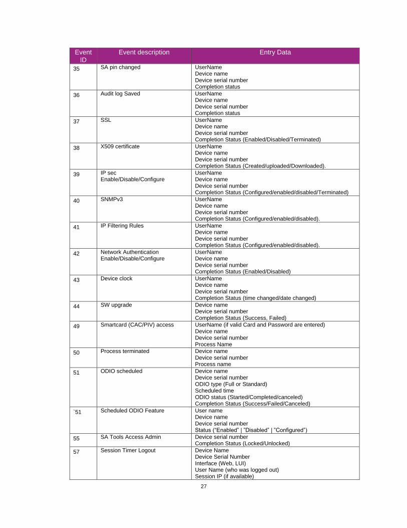
27
Event ID
Event description Entry Data
35 SA pin changed UserName Device name Device serial number Completion status
36 Audit log Saved UserName Device name Device serial number Completion status
37 SSL UserName Device name Device serial number Completion Status (Enabled/Disabled/Terminated)
38 X509 certificate UserName Device name Device serial number Completion Status (Created/uploaded/Downloaded).
39 IP sec Enable/Disable/Configure
UserName Device name Device serial number Completion Status (Configured/enabled/disabled/Terminated)
40 SNMPv3 UserName Device name Device serial number Completion Status (Configured/enabled/disabled).
41 IP Filtering Rules UserName Device name Device serial number Completion Status (Configured/enabled/disabled).
42 Network Authentication Enable/Disable/Configure
UserName Device name Device serial number Completion Status (Enabled/Disabled)
43 Device clock UserName Device name Device serial number Completion Status (time changed/date changed)
44 SW upgrade Device name Device serial number Completion Status (Success, Failed)
49 Smartcard (CAC/PIV) access UserName (if valid Card and Password are entered) Device name Device serial number Process Name
50 Process terminated Device name Device serial number Process name
51 ODIO scheduled Device name Device serial number ODIO type (Full or Standard) Scheduled time ODIO status (Started/Completed/canceled) Completion Status (Success/Failed/Canceled)
`51 Scheduled ODIO Feature User name Device name Device serial number Status (“Enabled” | ”Disabled” | ”Configured”)
55 SA Tools Access Admin Device serial number Completion Status (Locked/Unlocked)
57 Session Timer Logout Device Name Device Serial Number Interface (Web, LUI) User Name (who was logged out) Session IP (if available)

28
Event ID
Event description Entry Data
58 Session Timer Interval Change Device Name Device Serial Number Interface (Web, LUI)(Timer affected by change) User Name (who made this change) Session IP (if available) Completion Status
59 Feature Access Control Enable/Disable/Configure
User Name Device Name Device Serial Number Completion Status (Enabled/Disabled/Configured) Interface (Web, Local, CAC, SNMP) Session IP address (if available)
60 Device Clock NTP Enable/Disable
Device Name Device serial number Enable/Disable NTP NTP Server IP Address Completion Status (Success/Failed)
61 Grant / Revoke Admin Device Name Device Serial Number User Name (of target user) Grant or Revoke (the admin right) Completion Status (Success/Failed)
62 Smartcard (CAC/PIV) Enable/Disable/Configure
UserName Device Name Device Serial Number Completion Status (Success/Failed)
64 802.1x Enable/Disable/Configure
UserName Device Name Device Serial Number Completion Status (Success/Failed)
65 Abnormal System Termination Device Name Device Serial Number
66 Local Authentication UserName Device Name Device Serial Number Completion Status (Enabled/Disabled)
67 Web User Interface Authentication (Enable Network or Local)
UserName Device Name Device Serial Number Authentication Method Enabled (Network/Local)
68 FIPS Mode Enable/Disable/Configure17
UserName Device name Device Serial Number Enable/Disable/Configure
71 USB Port Enable/Disable
User Name Device Name Device Serial Number USB Port ID Completion Status (Enabled/Disabled)
73 System Log Download Username IP of requesting device (if available) File names downloaded Destination (IP address) Completion status (Success/failed)
17 For the new FIPS w/CC mode, there are audit log events triggered by these sequences: FIPS mode disabled-
>FIPS w/CC mode enabled: FIPS Mode Enable event, followed by FIPS Mode Configure event; FIPS w/CC mode
enabled-> FIPS w/CC mode disabled: FIPS Mode Config event followed by FIPS Mode Disable event; FIPS mode
enabled -> FIPS w/CC mode enabled: FIPS Mode Config event; FIPS w/CC mode enabled -> FIPS mode enabled:
FIPS Mode Config Event

29
Event ID
Event description Entry Data
80 SMTP Connection Encryption UserName Device name Device serial number Completion Status (Enabled for STARTLS / Enabled for STARTLS if Avail / Enabled for SSL/TLS / Disabled / Configured)
81 Email Domain Filtering Rule User name Device Name Device Serial Number Completion Status (Feature Enabled/Feature Disabled, Rule Added / Rule Deleted)
82 Software Self Test Started Device Name Device Serial Number
83 Software Self Test Complete Device Name Device Serial Number Completion Status(Success/Failed/Cancelled)
84 McAfee Security State
UserName Device name Device serial number Security Mode (Enhanced Security / Integrity Control) Completion Status (Enabled / Disabled / Pending)
85 McAfee Security Event
Device name Device serial number Type (Read / Modify / Execute / Deluge) McAfee message text
87 McAfee Agent
User name Device name Device serial number Completion Status (Enabled / Disabled)
88 Digital Certificate Import Failure Device name
89 User Name Add/Delete
Device serial number
90 User Name Password Change Security Mode
91 EFax Job Secure Print Passcode UserName (managing passcodes) Device name Device serial number Completion Status (Passcode Created/Changed)
92 Scan2Mailbox Folder Password Change
UserName (managing passwords) Device name Device serial number Folder Name Completion Status (Password was Changed)
93 EFax Mailbox Passcode UserName (managing passcodes) Device name Device serial number Completion Status (Passcode Created/Changed)
94 FTP/SFTP Filing Passive Mode User Name Device Name Device Serial Number Completion Status (Enabled / Disabled)
95 EFax Forwarding Rule User Name Device Name Device Serial Number Fax Line 1 or 2 (if applicable) Completion Status (Rule Edit / Rule Enabled / Rule Disabled)

30
Event ID
Event description Entry Data
99 Network Connectivity Enable / Disable
UserName Device name Device serial number Completion Status (Enable Wireless / Disable Wireless (Enable Wired /Disable Wired)
102 SW upgrade enable / disable UserName Device name Device serial number Completion Status (Enable Installation / Disable Installation)
105 IPv4 Enable/Disable/Configure
UserName Device name Device serial number Completion Status (Enabled Wireless/Disabled Wireless/ Configured Wireless) (Enabled Wired/Disabled Wired/ Configured Wired)
106 SA PIN Reset Device serial number Completion Status (Success/Failed)
109 Efax Passcode Length UserName (managing passcodes) Device name Device serial number Completion Status (Passcode Length Changed)
116 EWS Access/Configure UserName Device name Device serial number Completion Status (Standard Access, Open Access, Restricted)
117 System log push to Xerox Username if authenticated Server destination URL Log identifier string (filename) Completion Status (Success / Failed)
124 Invalid Login Attempt Lockout
Device name Device serial number Interface (EWS, Local UI) Session IP Address if available
125 Protocol audit Log enable/Disable
UserName Device Name Device serial number Completion Status Enable / Disable
127 Invalid Login Lockout Expires
Device name Device serial number Interface (EWS) Session IP Address if available Count of invalid attempts: “attempts xx” where xx = the number of attempts.
128 Erase Customer Data
Erase Customer Data Device serial number Success / Failed
129 Audit log SFTP scheduled Configure
UserName Device Name Device serial number Completion status (Enable/Disable/Configured)
130 Audit Log SFTP Transfer
UserName Device Name Device serial number Destination server Completion Status (File Transmitted)

31
Event ID
Event description Entry Data
131 Remote Software Download Enable Disable
UserName Device name Device serial number Completion Status (Enable/Disable)
144 User or Group Role Assignment
User name Device name Device serial number User or group name (assigned) Role name Action (added/removed)
145 User Permission Role User name Device name Device serial number Role name Completion status (Created / Deleted / Configured)
146 Admin Password Policy Configure User name Device name Device serial number
147 Local user account password policy
User name Device name Device serial number
148 Restricted admin login User name Device name Device serial number Completion status: “Success” or “Failed”
149 Grant / revoke restricted admin rights
User name (of user making the change) Device name Device serial number User name (of target user) Action: “Grant” or “Revoke”
150 Manual session logout Device Name Device Serial Number Interface (Web, LUI, CAC) User Name (who was logged out) Session IP (if available)
151 IPP Enable/Disable/Configure User name Device name Device serial number Completion status: (“Enabled” / “Disabled” / “Configured”)
152 HTTP Proxy Server Enable/Disable/Configure
User name Device name Device serial number Completion status: (“Enabled” / “Disabled” / “Configured”)
154 Restricted Admin Permission Role User name Device name Device serial number Restricted admin role name Completion status (Created / Deleted / Configured)
156 Lockdown and Remediate Security
User name Device Name Device Serial number Completion status: (“Enabled” / “Disabled”)
157 Lockdown Security Check Complete
User name (if available. “SYSTEM”, if executed as a scheduled event) Device name Device serial number Completion status (“Success” / “Failed”)
158 Lockdown Remediation Complete User name (if available. “SYSTEM”, if executed as a scheduled event) Device name Device serial number Completion status (“Success” / “Failed”)

32
Event ID
Event description Entry Data
159 Send Engineering Logs on Data Push
User name (if available) Device name Device serial number Current setting (“Enabled” / “Disabled”)
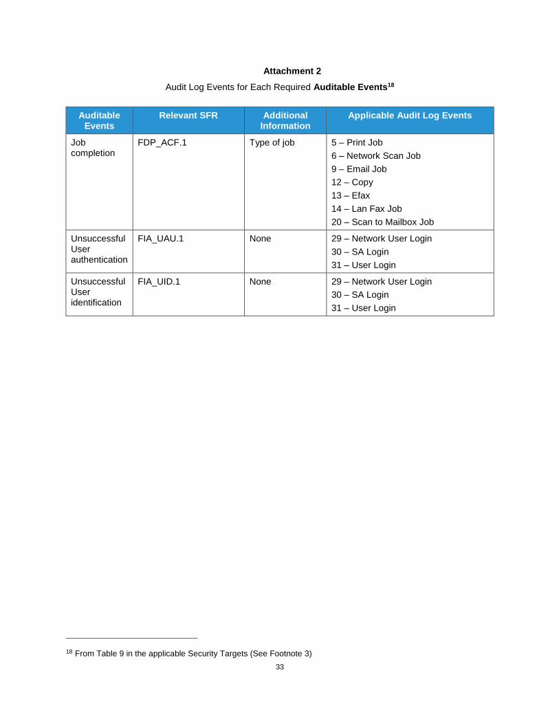
33
Attachment 2
Audit Log Events for Each Required Auditable Events18
Auditable Events
Relevant SFR Additional Information
Applicable Audit Log Events
Job completion
FDP_ACF.1 Type of job 5 – Print Job
6 – Network Scan Job
9 – Email Job
12 – Copy
13 – Efax
14 – Lan Fax Job
20 – Scan to Mailbox Job
Unsuccessful User authentication
FIA_UAU.1 None 29 – Network User Login
30 – SA Login
31 – User Login
Unsuccessful User identification
FIA_UID.1 None 29 – Network User Login
30 – SA Login
31 – User Login
18 From Table 9 in the applicable Security Targets (See Footnote 3)

33
Use of management functions
FMT_SMF.1 None 5 – Manual ODIO Standard started
10 – Audit Log Disabled
11 – Audit Log Enabled
16 – Manual ODIO Full started
33 – Audit Log download
34 – IIO Feature Status
36 – Audit log Saved
37 - SSL
38 – X509 certificate
39 – IP sec
41 – IP Filtering Rules
42 – Network Authentication
51 – ODIO scheduled
58 – Session Timer Interval Change
60 – Device Clock NTP
61 – Grant/Revoke Admin
62 – Smartcard (CAC/PIV)
64 – 802.1x
80 – SMTP Connection Encryption
84 – McAfee Security State
89 – User Name Add/Delete
90 – User Name Password Change
94 – FTP/SFTP Filing Passive Mode
95 – EFax Forwarding Rule
109 – EFax Passcode Length
128 – Erase Customer Data
129 – Audit log SFTP scheduled
130 – Audit Log SFTP Transfer
144 – User or Group Role Assignment
145 – User Permission Role
146 – Admin Password Policy Configure
147 – Local user account password policy

34
Modification to the group of Users that are part of a role
FMT_SMR.1 None 144 – User or Group Role Assignment
145 – User Permission Role
Changes to the time
FPT_STM.1 None 43 – Device Clock
60 – Device Clock NTP
Failure to establish session
FTP_ITC.1, FTP_TRP.1(a), FTP_TRP.1(b)
Reason for failure
Protocol Log (see I.b.12)

2
Attachment 3 Standard Ports
Port Type Service Name
80 or 443 TCP
HTTP including: Web User Interface UPnP Discovery Web Services for Products (WSD) WebDAV
631 or 443 TCP HTTP (IPP)
137 UDP NETBIOS (Name Service)
138 UDP NETBIOS (Datagram Service)
161 UDP SNMP
427 TCP/UDP SLP
500 & 4500 UDP IPSec
515 TCP LPR
631 TCP IPP
1900 UDP SSDP
3702 TCP WSD (Discovery)
5353 UDP mDNS
9100 TCP Raw IP (also known as JetDirect, AppSocket or PDL-datastream)
5909-5999 TCP Remote Access to local display panel. Port is randomly selected and communications encrypted with TLS 1.2.
53202 TCP WSD Transfer
53303 TCP WSD Print
53404 TCP WSD Scan

3