serie 712 - asset.conrad.com€¦ · 712 712-2 Ü ti 620 702 709 710 711 712 719 423 425 440 581...
TRANSCRIPT
Serie 712

712
712-2
Ü
TI
620
702
709
710
711
712
719
423
425
440
581
678
680
682
720
723
623
690
691
692
693
694
707
713
718
733
763
765
768
714
715
766
815
820
825
876
772
775
A
B
C
R
712
712-3
Ü
TI
620
702
709
710
711
712
719
423
425
440
581
678
680
682
720
723
623
690
691
692
693
694
707
713
718
733
763
765
768
714
715
766
815
820
825
876
772
775
A
B
C
R
1
3 4
2
Subminiatur Rundsteckverbinder Serie 712Subminiature circular connectors series 712
KurzinformationBrief information
Kabelsteckverbinder• Steckverbinder mit Schraubverriegelung• Schutzart IP 67 1)
• Metallgehäuse 360° EMV-sicher geschirmt• Einfache Montage• Kompatibel zu Steckverbinderserie 702
Flanschsteckverbinder1 Standard: mit Lötanschluss, wird von vorn eingesetzt und von hinten verschraubt.2 Mit Lötanschluss für die Verschraubung von vorne. Besonders geeignet für vorkonfektionierte Kabelbäume, die nach dem Löten eingebaut werden.3 Mit Tauchlötanschluss für den Anschluss für Leiterplatten.4 Mit Tauchlötanschluß, für direkte Schirmübertragung auf die Leiterplatte
Maßstab 1 : 1/
Cable Connector• Connector with screw locking• Degree of protection IP 67 1 )
• Metal housing with 360° EMI protected shielding• Easy assembly• Compatible to series 702
Chassis sockets1 Standard: with solder termination, mounted from front side and fastened from back side.2 With solder termination, mounted from front side and fastened from back side. Especially suited for preassembled cable trees which are mounted after soldering.3 Dip solder termination for connection to PCB.4 Dip solder termination, for direct connection to the of shield PCB.
Scale 1 : 1
1) Erläuterung der Schutzarten siehe Seite TI-3 – TI-4. / 1) Explanation of protection standards see page TI-3 – TI-4.
Aufbau des Steckverbinders:Construction of the connector:
Standard VersionStandard version
Metall, (EMV) VersionMetal, (EMI) version
Winkel VersionAngled version

712
712-2
Ü
TI
620
702
709
710
711
712
719
423
425
440
581
678
680
682
720
723
623
690
691
692
693
694
707
713
718
733
763
765
768
714
715
766
815
820
825
876
772
775
A
B
C
R
712
712-3
Ü
TI
620
702
709
710
711
712
719
423
425
440
581
678
680
682
720
723
623
690
691
692
693
694
707
713
718
733
763
765
768
714
715
766
815
820
825
876
772
775
A
B
C
R
Allgemeine Kennwerte General Characteristics
Polzahl
Verriegelung
Anschlussart
Anschlussquerschnitt in mm2
Anschlussquerschnitt in AWG
Kabeldurchlass
Schutzart Gehäuse
Mechanische Lebensdauer
Obere Grenztemperatur
Untere Grenztemperatur
Gewicht Kabelsteckverbinder
Gewicht Flanschsteckverbinder
Elektrische Kennwerte
Bemessungsspannung
Bemessungs-Stoßspannung
Verschmutzungsgrad
Überspannungskategorie
Isolierstoffgruppe
Prüfstoßspannung
Bemessungsstrom (40 °C)
Durchgangswiderstand
Isolationswiderstand
Werkstoffe
Kontaktstift
Kontaktbuchse
Kontaktoberfläche
Steckerkörper
Buchsenkörper
Gehäuse Kabelsteckverbinder
Flanschgehäuse
Gewindering
Number of contacts
Locking system
Termination
Wire gauge in mm2
Wire gauge in AWG
Cable Outlet
Shell protection
Mechanical operation
Upper temperature
Lower temperature
Weight cable connector
Weight socket
Electrical Characteristics
Rated voltage
Rated impulse voltage
Pollution degree
Overvoltage categorie
Material group
Test voltage
Rated current (40 °C)
Contact resistance
Insulation resistance
Materials
Pin contact
Socket contact
Contact plating
Male insert
Female Insert
Housing cable connector
Socket
Ring nut
2
schrauben / screw
löten, tauchlöten / solder, dip solder
max. 0,25
> 500 Steckzyklen / > 500 mating cycles
+ 85 °C (+ 185 °F)
– 40 °C (– 40 °F)
~ 8 g (18 g Metallgehäuse / 18 g metall housing)
125 V
1500 V
1
II
III
1750 V
4 A 3 A 1 A
< 3 mΩ
> 10 10 Ω
CuZn (Messing/brass)
CuSn (Bronze/bronce)
Au (Gold/gold)
PBT (UL 94 V-0)
PA 66 (UL 94 V-0)
max. 0,14
3 4 5 7 8
IP 67
PA 66 (UL 94 HB)
CuZn (Messing, vernickelt/brass, nickel plated)
CuZn (Messing, vernickelt/brass, nickel plated)
max. 24 max. 26
Subminiatur Rundsteckverbinder Serie 712Subminiature circular connectors series 712
Technische Daten 1)
Specifications 1)
3,5 - 5 mm (.12 - .20 in.)
~ 5 g
1) Normen und Prüfbedingungen für diese Angaben siehe Seite TI-16. / 1) Standards and test parameters for this data see page TI-16.

712
712-4
Ü
TI
620
702
709
710
711
712
719
423
425
440
581
678
680
682
720
723
623
690
691
692
693
694
707
713
718
733
763
765
768
714
715
766
815
820
825
876
772
775
A
B
C
R
712
712-5
Ü
TI
620
702
709
710
711
712
719
423
425
440
581
678
680
682
720
723
623
690
691
692
693
694
707
713
718
733
763
765
768
714
715
766
815
820
825
876
772
775
A
B
C
R
2
3
4
5
7
8
2
3
4
5
7
8
2
3
4
5
7
8
2
3
4
5
7
8
Subminiatur Rundsteckverbinder Serie 712Subminiature circular connectors series 712
PolzahlContacts
Bestell-Nr.Ordering-No.
KabelsteckerMale cable connector
Bezeichnung – AbbildungDescription – Figure
Kabelstecker 360° EMV sicherMale cable connector 360° EMI protected
WinkelsteckerMale angled connector
Winkelstecker360° EMV sicherMale angled connector 360° EMI protected
MaßzeichnungDrawing
KabelsteckerMale cable connectors
~ 40~ 1.6
~ 32~ 1.26
Ø 11
,5Ø
.453
M 9,0
x 0,5
~ 40~ 1.6
Ø 14
,0Ø
.551
M 9,0
x 0,5
Ø 14
,0Ø
.551
M9x0
,5
Ø 11,4Ø .44921,5
.846
28,51.12222,5
.886
~ 30
~1.1
81
Kabel Ø 3,5 - 5,0cable Ø .138 - .197Ø 13,0
.512
Ø 15
,0.59
1
Ø 14
,0.55
1
331.30
99-0401-00-02
99-0405-00-03
99-0409-00-04
99-0413-00-05
99-0421-00-07
99-0425-00-08
99-0401-10-02
99-0405-10-03
99-0409-10-04
99-0413-10-05
99-0421-10-07
99-0425-10-08
99-0401-70-02
99-0405-70-03
99-0409-70-04
99-0413-70-05
99-0421-70-07
99-0425-70-08
99-0401-75-02
99-0405-75-03
99-0409-75-04
99-0413-75-05
99-0421-75-07
99-0425-75-08

712
712-4
Ü
TI
620
702
709
710
711
712
719
423
425
440
581
678
680
682
720
723
623
690
691
692
693
694
707
713
718
733
763
765
768
714
715
766
815
820
825
876
772
775
A
B
C
R
712
712-5
Ü
TI
620
702
709
710
711
712
719
423
425
440
581
678
680
682
720
723
623
690
691
692
693
694
707
713
718
733
763
765
768
714
715
766
815
820
825
876
772
775
A
B
C
R
2
3
4
5
7
8
2
3
4
5
7
8
2
3
4
5
7
8
2
3
4
5
7
8
Subminiatur Rundsteckverbinder Serie 712Subminiature circular connectors series 712
PolzahlContacts
KabeldoseFemale cable connector
Bezeichnung – AbbildungDescription – Figure
Kabeldose360° EMV sicherFemale cable connector 360° EMI protected
WinkeldoseFemale angled connector
Winkeldose 360° EMV sicherFemale angeled connector 360° EMI protected
MaßzeichnungDrawing
KabeldosenFemale cable connectors
Ø 11
,5Ø
.453
M 9,0
x 0,5
~ 36~ 1.4
~ 35~ 1.38
~ 36~ 1.4
M 9,0
x 0,5
Ø 14
,0.55
1
26,51.0420,5
.807
M9x0
,5
Ø 14
,0.55
1
Ø 11,4.449
Bestell-Nr.Ordering-No.
~ 30
~1.1
81
Kabel Ø 3,5 - 5,0cable Ø .138 - .197Ø 13,0
.512
Ø 15
,0.59
1
Ø 14
,0.55
1
301.18
99-0402-00-02
99-0406-00-03
99-0410-00-04
99-0414-00-05
99-0422-00-07
99-0426-00-08
99-0402-10-02
99-0406-10-03
99-0410-10-04
99-0414-10-05
99-0422-10-07
99-0426-10-08
99-0402-70-02
99-0406-70-03
99-0410-70-04
99-0414-70-05
99-0422-70-07
99-0426-70-08
99-0402-75-02
99-0406-75-03
99-0410-75-04
99-0414-75-05
99-0422-75-07
99-0426-75-08
712
712-6
Ü
TI
620
702
709
710
711
712
719
423
425
440
581
678
680
682
720
723
623
690
691
692
693
694
707
713
718
733
763
765
768
714
715
766
815
820
825
876
772
775
A
B
C
R
712
712-7
Ü
TI
620
702
709
710
711
712
719
423
425
440
581
678
680
682
720
723
623
690
691
692
693
694
707
713
718
733
763
765
768
714
715
766
815
820
825
876
772
775
A
B
C
R
2
3
4
5
7
8
2
3
4
5
7
8
2
3
4
5
7
8
–
–
–
–
7
8
2
3
4
5
7
8
2
3
4
5
7
8
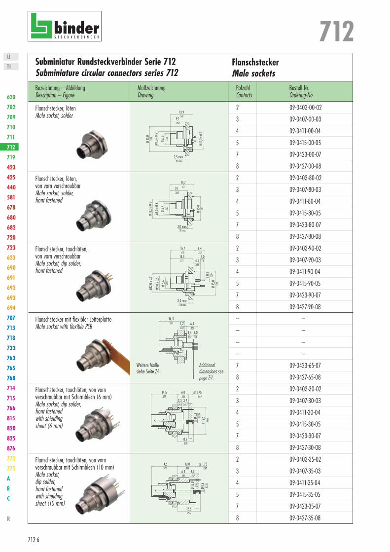
Subminiatur Rundsteckverbinder Serie 712Subminiature circular connectors series 712
FlanschsteckerMale sockets
Bestell-Nr.Ordering-No.
MaßzeichnungDrawing
Bezeichnung – AbbildungDescription – Figure
Flanschstecker, lötenMale socket, solder
Flanschstecker, löten,von vorn verschraubbarMale socket, solder,front fastened
Flanschstecker, tauchlöten, von vorn verschraubbarMale socket, dip solder,front fastened
Flanschstecker mit flexibler LeiterplatteMale socket with flexible PCB
Flanschstecker, tauchlöten, von vornverschraubbar mit Schirmblech (6 mm)Male socket, dip solder,front fastenedwith shieldingsheet (6 mm)
Flanschstecker, tauchlöten, von vornverschraubbar mit Schirmblech (10 mm)Male socket,dip solder,front fastenedwith shieldingsheet (10 mm)
PolzahlContacts
13,9.547
9,1.358
M12,0
x 0,5
2,5 max..10 max.
Ø 6,6 .26
0
M9,0
x 0,5
Ø 15
,0.59
0
15,7.629,1
.358
M12,
0 x 0
,5
3,0 max..118 max.
Ø 6,
6.2
60
M9,0
x 0,
5
Ø 15
,0.5
90
15,7.615
M12,0
x 0,5
3,0 max..118 max.
Ø 6,6 .26
0
M9,0
x 0,5
Ø 15
,0.59
0
6,4.252
3,0.118
14,5.571 4,6
.181
Ø 0,6
.0354
14,5.571 1,2
.0476,4.252
3,0.118
3,4.134
8,6.338
Ø 0,6
.0236
Ø 15
,0.59
0
14,5.571
6,0.236
≤ 1,75.069
3,7.1457
2,3.091
14,5.571
≤ 1,75.069
3,7.1457
12,6.496
10,0.394
6,3.248
Ø 0,6
.0236
Ø 15
,0.59
0
09-0403-00-02
09-0407-00-03
09-0411-00-04
09-0415-00-05
09-0423-00-07
09-0427-00-08
09-0403-80-02
09-0407-80-03
09-0411-80-04
09-0415-80-05
09-0423-80-07
09-0427-80-08
09-0403-90-02
09-0407-90-03
09-0411-90-04
09-0415-90-05
09-0423-90-07
09-0427-90-08
–
–
–
–
09-0423-65-07
09-0427-65-08
09-0403-30-02
09-0407-30-03
09-0411-30-04
09-0415-30-05
09-0423-30-07
09-0427-30-08
09-0403-35-02
09-0407-35-03
09-0411-35-04
09-0415-35-05
09-0423-35-07
09-0427-35-08
Weitere Maße siehe Seite Z-1.
Additional dimensions see page Z-1.

712
712-6
Ü
TI
620
702
709
710
711
712
719
423
425
440
581
678
680
682
720
723
623
690
691
692
693
694
707
713
718
733
763
765
768
714
715
766
815
820
825
876
772
775
A
B
C
R
712
712-7
Ü
TI
620
702
709
710
711
712
719
423
425
440
581
678
680
682
720
723
623
690
691
692
693
694
707
713
718
733
763
765
768
714
715
766
815
820
825
876
772
775
A
B
C
R
2
3
4
5
7
8
2
3
4
5
7
8
2
3
4
5
7
8
–
–
–
–
7
8
2
3
4
5
7
8
2
3
4
5
7
8
Subminiatur Rundsteckverbinder Serie 712Subminiature circular connectors series 712
FlanschdosenFemale sockets
MaßzeichnungDrawing
Bezeichnung – AbbildungDescription – Figure
Flanschdose, lötenFemale socket, solder
Flanschdose, löten, von vorn verschraubbarFemale socket, solder, front fastened
Flanschdose, tauchlöten, von vorn verschraubbarFemale socket, dip solder,front fastened
Flanschdose mit flexibler LeiterplatteFemale socket with flexible PCB
Flanschdose, tauchlöten, von vornverschraubbar mit Schirmblech (6 mm)Female socket,dip solder,front fastenedwith shieldingsheet (6 mm)
Flanschdose, tauchlöten, von vornverschraubbar mit Schirmblech (10 mm)Female socket,dip solder,front fastenedwith shieldingsheet (10 mm)
PolzahlContacts
M12,0
x 0,5
2,5 (2-5 pol.).10
M9,0
x 0,5
Ø 15
,0.59
0
11,2.441
10,0.394
3,2 (7+8 pol.).126
max. 3,0max. .118
11,5.453
3,2 (7+8 pol.).126
2,5 (2-5 pol.).10
M12,0
x 0,5
M9,0
x 0,5
Ø 15
,0.59
0
max. 3,0max. .118
3,7.146
4,6.181
11,5.453
3,2 (7+8 pol.).126
4,8.190
3,2 (2-5 pol.).126
M12,0
x 0,5
M9,0
x 0,5
Ø 15
,0.59
0Ø 0,6
.0236
max. 3,0max. .118
3,7.146
4,6.181
3,2.126
11,5.459
3,7.146
5,1.201
< 1,75.069
3,7.1457
6.236
2,3.091
Ø 0,6
.0236
Ø 15
.590
12,8.504
6,6.260
Bestell-Nr.Ordering-No.
≤ 1,75.069
3,7.1457
10,0.394
6,3.248
Ø 0,6
.0236
Ø 15
,0.59
0
12,8.504
6,6.260
Weitere Maße siehe Seite 712-11Additional dimensions see page 712-11
09-0404-00-02
09-0408-00-03
09-0412-00-04
09-0416-00-05
09-0424-00-07
09-0428-00-08
09-0404-80-02
09-0408-80-03
09-0412-80-04
09-0416-80-05
09-0424-80-07
09-0428-80-08
09-0404-90-02
09-0408-90-03
09-0412-90-04
09-0416-90-05
09-0424-90-07
09-0428-90-08
–
–
–
–
09-0424-65-07
09-0428-65-08
09-0404-30-02
09-0408-30-03
09-0412-30-04
09-0416-30-05
09-0424-30-07
09-0428-30-08
09-0404-35-02
09-0408-35-03
09-0412-35-04
09-0416-35-05
09-0424-35-07
09-0428-35-08
712
712-8
Ü
TI
620
702
709
710
711
712
719
423
425
440
581
678
680
682
720
723
623
690
691
692
693
694
707
713
718
733
763
765
768
714
715
766
815
820
825
876
772
775
A
B
C
R
712
712-9
Ü
TI
620
702
709
710
711
712
719
423
425
440
581
678
680
682
720
723
623
690
691
692
693
694
707
713
718
733
763
765
768
714
715
766
815
820
825
876
772
775
A
B
C
R
2 pol 3 pol 4 pol
5 pol 7 pol 8 pol
Subminiatur Rundsteckverbinder Serie 712Subminiature circular connectors series 712
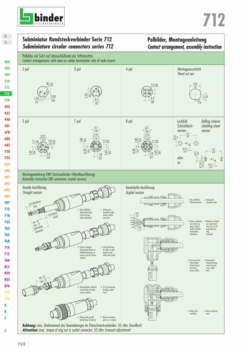
Polbilder, MontageanleitungContact arrangement, assembly instruction
MontageausschnittPanel cut out
Montageanleitung EMV Steckverbinder (Metallausführung)Assembly instruction EMI connectors (metal version)
Polbilder mit Sicht auf Lötanschlußseite der StifteinsätzeContact arrangements with view on solder termination side of male inserts
4. Übrige Teile gemäßDarstellung montieren
4. Mount remainingparts acc. to figure
3. Überstehendes Geflechtabschneiden, Kontakt-einsatz anlöten
3. Cut off projectingbraiding, solderinsert
2. Schirm umlegen,Schirmmanschette anKabeldurchmesser an-passen und mit Schirmverlöten
2. Fold shield back,fit collar to cablediameter andsolder with shield
1. Teile auffädeln,Kabel abmanteln,Schirm kürzen,Leiter abisolieren
1. String parts,dismantle cable,shorten shield,strip wire
min. 10
max. 12
min. 10
max. 12
abmanteln
dismantle
3,0 abisolieren
strip
~ 4,0 Schirm
shield
2. Schirm aufweiten,um Schirmringlegen, überste-hendes Geflechtabschneiden,abisolieren
2. Widening of shield,put around shiel-ding ring, cut offprojecting brai-ding,dismantle
3. Litzen durch Ge-häuse fädeln,Druckschraubemontieren,Litzen anlöten
3. Thread wiresthrough housing,mount pressingscrew, solderwires
4. Übrige Teilemontieren
4. Mount remainingparts
1. Teile auffädeln,Kabel abmanteln
1. String parts,dismantle cable
~3,0~.118
~20~.78
Lochbild Schirmblech-version
Drilling schemeshielding sheet version
12,5.4921
Ø 0,9.0354
Ø 3,0 .11
8
12,5.4921
Ø 0,9.0354
1,8±0
,1
.0709
Ø 1,3
±0,1
.0512
(4x)
12,5.4921
Ø 0,9.0354
Ø 3,0 .11
8
12,5.4921
Ø 0,9.0354
1,8±0
,1
.0709
Ø 1,3
±0,1
.0512
(4x)
oder:or:
5,1 .201
12,0.472
R1,4
12
1,09.043
1,09
.043
1,55.061
1 3
3,1.122
1,55
.061
2
2,2.087
2,2 .087
12 3
4
2,0.079
0,52
.0205
12
34
5
1,7 .067
1,37
.054
3,22.127
1,8.071
1,2 .047
123 4 5
1,85
.073
0,35
.014
3,7.146
67
2,9.114
1,65
.065
1,8.071
1,2 .047
123 4 5
1,85
.073
0,35
.014
3,7.146
67
2,9.114
1,65
.065
Achtung: max. Drehmoment des Gewinderinges im Flanschsteckverbinder: 50 cNm (handfest)Attention: max. torque of ring nut in socket connector: 50 cNm (manual adjustment)
Gerade AusführungStraight version
Gewinkelte AusführungAngled version

712
712-8
Ü
TI
620
702
709
710
711
712
719
423
425
440
581
678
680
682
720
723
623
690
691
692
693
694
707
713
718
733
763
765
768
714
715
766
815
820
825
876
772
775
A
B
C
R
712
712-9
Ü
TI
620
702
709
710
711
712
719
423
425
440
581
678
680
682
720
723
623
690
691
692
693
694
707
713
718
733
763
765
768
714
715
766
815
820
825
876
772
775
A
B
C
R
Subminiatur Rundsteckverbinder Serie 712Subminiature circular connectors series 712
EinzelteildarstellungComponent part drawing
WinkelsteckverbinderAngled cable connector
KabelsteckverbinderCable connector
Kabelsteckverbinder EMV VersionCable connector EMI version
Winkelsteckverbinder EMV VersionAngled cable connector EMI version
Schnapphülsesnap bushGewindering Stecker
connection ring male connector
Steckereinsatzmale insert
Flachdichtungflat seal
Druckschraubepressing screw
Dichtringseal
Klemmkorbpinch ring
Gewindering Doseconnection ring female connector
Buchseneinsatzfemale insert
O-Ring 6x1o-ring
Schnapphülsesnap bushing
Gewindering Steckerconnection ring male connector
Steckereinsatzmale insert
Flachdichtungflat seal
Druckschraubepressing screw
Dichtringseal
Klemmkorbpinch ring
Gewindering Doseconnection ring female connector
Buchseneinsatzfemale insert
O-Ring 6x1o-ring
Gewindering Stecker kpl.connection ring male connector
Steckereinsatz lötenmale insert solder
Dichtringseal
Druckschraubepressing screw
Dichtungseal
Winkelgehäuseangled housing
Gewindering Dose kpl.connection ring female connector
Buchseneinsatz lötenfemale insert solder
Klemmkorbpinch ring
O-Ring 6x1o-ring
Verschlussschraubescrew plug
Schirmringshield ring
Druckschraubepressing screw
Dichtringseal
Klemmkorbpinch ring
Gewindering Stecker mont.connection ring male connector
Steckereinsatzmale insert
O-Ring 6x1,5o-ring
O-Ring 6x1o-ring
O-Ring 6x1,5o-ring
Winkelgehäuseangled housing
Achtung: max. Drehmoment des Gewinderinges im Flanschsteckverbinder: 50 cNm (handfest)Attention: max. torque of ring nut in socket connector: 50 cNm (manual adjustment)

712
712-10
Ü
TI
620
702
709
710
711
712
719
423
425
440
581
678
680
682
720
723
623
690
691
692
693
694
707
713
718
733
763
765
768
714
715
766
815
820
825
876
772
775
A
B
C
R
712
712-11
Ü
TI
620
702
709
710
711
712
719
423
425
440
581
678
680
682
720
723
623
690
691
692
693
694
707
713
718
733
763
765
768
714
715
766
815
820
825
876
772
775
A
B
C
R
Subminiatur Rundsteckverbinder Serie 712Subminiature circular connectors series 712
ZubehörAccessories
AbbildungFigure
MaßzeichnungDrawing
Bestell-Nr.Ordering-No.
BezeichnungDescription
Schutzkappe für Kabelstecker, IP 67Protection cap for male cable connector, IP 67
Schutzkappe für Kabeldose, IP 67Protection cap for female cable connector, IP 67
Schutzkappe für Flanschstecker, IP 67Protection cap for male sockets, IP 67
Schutzkappe für Flanschdose, IP 67Protection cap for female sockets, IP 67
Viereckflansch mit DichtungSquare flange with seal
Lötösenring (Schutzart kann sich verringern)Solder eye ring (Degree of protection may be reduced)
6-kant Mutter mit Rändel 2 mm, 4 mmHexagonal nut 2 mm, 4 mm
MontageschlüsselMounting spanner
~45,0~1.77
Ø 10,0
.349
5,0.197
verschiebbarmovable
~45,0~1.77
Ø 10,0
.349
5,0.197
verschiebbarmovable
~35,0~.138
3,4 .134
~35,0~.138
3,4 .134
Ø 12
,1.47
6
0,3.0012
23,0.91
5,7.224
Ø 1,5.060
4,0 .157
Ø 15
,0.59
Ø 15
,0.59
SW 14,0
M12,0
x 0,5
4,0.157
Ø 14
,5.55
M12,0
x 0,5
2,0.079
Ø 14
,5.55
12,1.473
20,0
.787
0,8.0315Ø
2,6 .102
15,0
.591
271.06
Ø 10 .39
08-0349-000-001
08-0350-000-001
08-0351-000-001
08-0352-000-001
08-1124-000-001
04-0208-002
01-0013-001(2 mm)
01-5023-001(4 mm)
01-5059-001
712
712-10
Ü
TI
620
702
709
710
711
712
719
423
425
440
581
678
680
682
720
723
623
690
691
692
693
694
707
713
718
733
763
765
768
714
715
766
815
820
825
876
772
775
A
B
C
R
712
712-11
Ü
TI
620
702
709
710
711
712
719
423
425
440
581
678
680
682
720
723
623
690
691
692
693
694
707
713
718
733
763
765
768
714
715
766
815
820
825
876
772
775
A
B
C
R
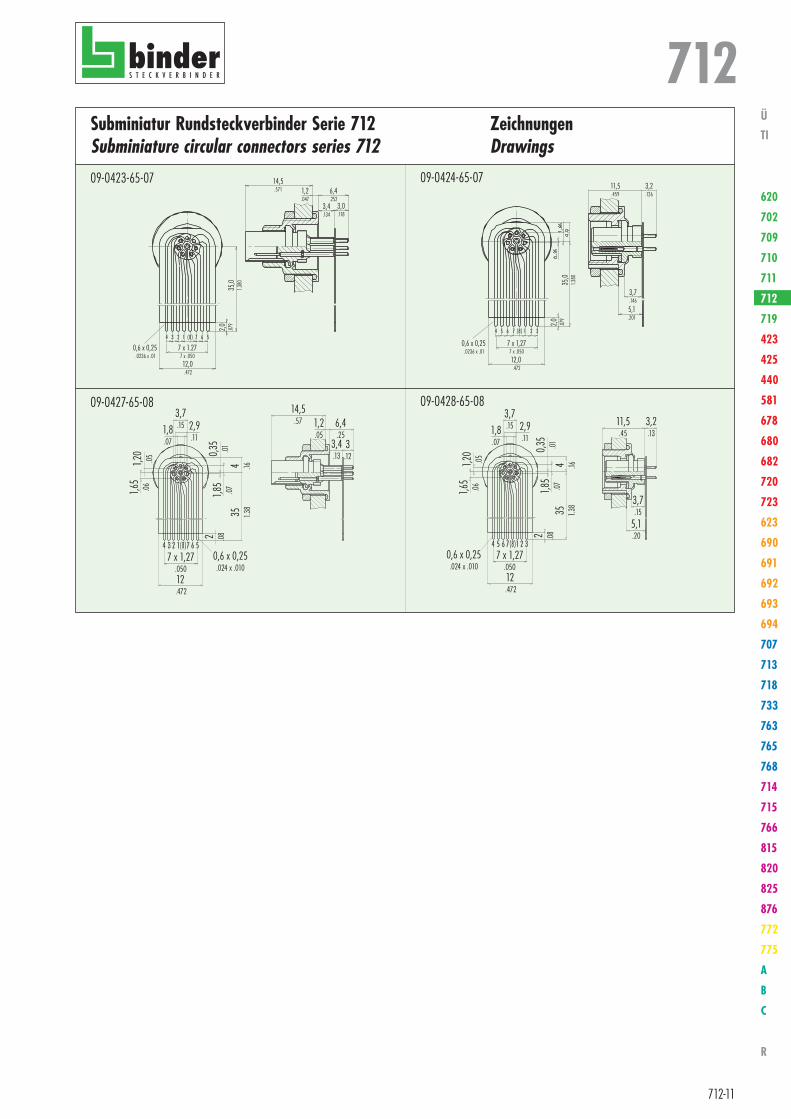
Subminiatur Rundsteckverbinder Serie 712Subminiature circular connectors series 712
ZeichnungenDrawings
35,0
1.380
2,0 .079
0,6 x 0,25 .0236 x .01
4 3 2 1 (8) 7 6 5
12,0 .472
7 x 1.277 x .050
14,5.571 1,2
.0476,4.252
3,0.118
3,4.134
09-0423-65-07
7 x 1,27.050
2 .08
1,65
.06
3,7.15 2,9
.11
4 .16
0,35
.0135 1.3
8
0,6 x 0,25.024 x .010
4 3 2 7 6 51
1,8.07
1,20
.05
1,85
.07
12 .472
(8)
14,5.57 1,2
.056,4.25
3.12
3,4.13
09-0427-65-08
3,2.126
11,5.459
3,7.146
5,1.201
35,0
1.380
2,0 .079
0,6 x 0,25 .0236 x .01
4 5 6 7 (8) 1 2 3
12,0 .472
7 x 1,277 x .050
09-0424-65-07
09-0428-65-08
7 x 1,27.050
2 .08
1,65
.06
3,7.15 2,9
.11
4 .16
0,35
.0135 1.3
8
0,6 x 0,25.024 x .010
1,8.07
1,20
.05
1,85
.07
12 .472
4 5 6 1 2 37(8)
11,5.45
3,2.13
3,7.15
5,1.20

712
712-12
Ü
TI
620
702
709
710
711
712
719
423
425
440
581
678
680
682
720
723
623
690
691
692
693
694
707
713
718
733
763
765
768
714
715
766
815
820
825
876
772
775
A
B
C
R