service and repair manual - general transmissions · service and repair manual 39011.c. ... general...
TRANSCRIPT

Transaxle Type RT400
Service and Repair Manual
39011.CJan. 2016

Table of content
This document is our property. It can't be used, duplicated or given to third parties without our written authorization 2
- Table of content………………………………………………………………………………… 2- Introduction………………………………………………………………………………………. 2-External Controls and Functions………………………………………………………. 3-Product Identification…………………………………………………….…..……………… 4-Safety…………………………………………………………………………………………………. 4-Preliminary check before tearing down the transmission……………………. 5-Preliminary check before re-install the transmission….…………….…………. 5-Troubleshooting…………………………………………………………………………………. 7-Repair Procedures………………………………………………………………………….…… 8 to 14-Exploded view………………………………………………………………………………….…. 15 to 20 -Notes…………………….…………………………………………………………………………... 21
IntroductionI- General Transmissions presentationWith 3 production sites, Mexico, China, France, and a policy focus on product quality and continuous innovation, General Transmission is a world leader in the design and manufacture of gearbox and transaxle, for lawn and garden equipment.
II- Manual introductionThe purpose of this manual is to provide service and repair information for the RT400 transaxle.Also included are exploded view, troubleshooting and repair procedures.
III- RT400 transaxle general descriptionThe RT400 transaxle is design to provide an infinitely variable speed range thru one pedal control, and a reverse operation thru an hand control. This transaxle also offer an integrate differential function and a neutral automatic braking.
IV- How to use this manualGeneral Transmissions recommend, before tearing down the RT400 transaxle, to make sure that you have a clean and organize work area, as well as the required specific tools.General Transmissions also recommend to carefully read the general instructions provided in the manual (p.5 to 6), before starting any reparation.After detected the potential defective component, using the troubleshooting, follow the repair procedures. It is necessary to complete the Preliminary operation, to be able to make the Replacement operation (see troubleshooting p.7). A defective component might cause premature wear or deterioration of other components. Make sure that all necessary kit have been replaced.For all service or repair operation, respect the shop and government safety rules.

External Controls and Functions
This document is our property. It can't be used, duplicated or given to third parties without our written authorization
Bypass lever:Allows you to move the vehicle with the engine off
Panic brake lever
Forward / Neutral / Reverse
Speed lever
Right wheel shaft Left wheel shaft
Belt drive pulley
3
Product identification
SafetyPersonal SafetySafety precautions must be observed while servicing or repairing the transmission. This section is to be used in conjunction with all other safety material which may apply, such as:-Local and shop safety rules.-Government safety laws and regulations.
Do not place speed above safety.
Wear appropriate clothing. Loose or hanging clothing can be hazardous. Use the appropriate safety equipment.
Tool SafetyUse the proper tools and equipment for the task.
Servicing SafetyCertain procedures may require the vehicle to be disabled.
This document is our property. It can't be used, duplicated or given to third parties without our written authorization
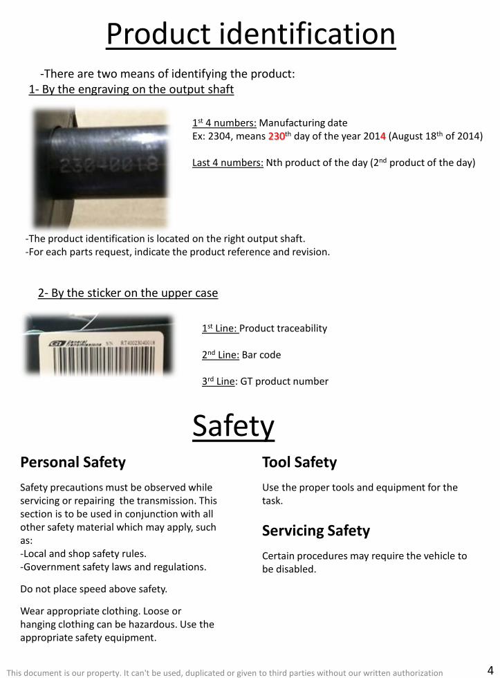
-The product identification is located on the right output shaft.-For each parts request, indicate the product reference and revision.
1st 4 numbers: Manufacturing dateEx: 2304, means 230th day of the year 2014 (August 18th of 2014)
Last 4 numbers: Nth product of the day (2nd product of the day)
-There are two means of identifying the product:1- By the engraving on the output shaft
2- By the sticker on the upper case
4
1st Line: Product traceability
2nd Line: Bar code
3rd Line: GT product number

General InstructionsPreliminary check before tearing down the transmission
Preliminary check before re-installing the transmission
- Clean up the transmission- Check all the linkages between tractor and transmission (see owner manual)- Check the belt routing- In case of failure in cold condition, check the transmission functionality after a while in a dry place. Failure might come from a frozen controls system.- Check the correct installation of the transmission (see view below)
This document is our property. It can't be used, duplicated or given to third parties without our written authorization
- Ensure that the variation belt is in the correct position.
5

This document is our property. It can't be used, duplicated or given to third parties without our written authorization
- Verify the position of the inversion rod.
- Verify the presence of the brake spring.
- Ensure that both variation levers are in the correct position.
6

Troubleshooting
This document is our property. It can't be used, duplicated or given to third parties without our written authorization
-All preliminary operations needs to be done, to be able to complete the replacement operation.
7
TROUBLESHOOTING CHECKLIST P.8 P.9 P.10 P.10 P.12 P.13 P.14
Customer complaints Potential failure Component to replace P/N OP 1 OP 2 OP 3 OP 4 OP 5 OP 6 OP 7
Loss of traction
Loss of power
Failure of the driven pulley driven kit MIA12482 R
Failure of the driver pulley driver kit MIA13031 R
Damage belt belt MIA12479 P P R
Broken cam cam kit MIA12475 P P R
Broken inversion kit inversion kit MIA12790 P P P R
Variation controls failure variation kit MIA12755 P P P P R
Internal failure transmission MIA12863
Loss of panic brake Broken brake lever
brake kit MIA12474
R
Loss of neutral brake function(Loss of speed range) Broken brake lever
R
R
Loss of neutral brake function Broken brake spring R
Loss of brake functions Internal failure transmission MIA12863
loss of bypass functionBroken bypass lever
brake kit MIA12474R
Broken plastic brake lever R
Improper disengaging in neutral positionDriver spring failure
driver kit MIA13031R
Driver bearing failure R
Loss of speed range
Damaged driven flanges driven kit MIA12482 R
Damaged driver flangesdriver kit MIA13031
R
Damaged main pulley flange R
Damaged belt belt MIA12479 P P R
Broken variation rod variation kit MIA12755 P P P P R
Vibration
Damaged driven flanges driven kit MIA12482 R
Damaged driver flanges driver kit MIA13031 R
Broken variation rod variation kit MIA12755 P P P P R
Noise
Damaged driven pulley driven kit MIA12482 R
Damaged driver pulley driver kit MIA13031 R
Damaged belt belt MIA12479 P P R
Damaged variation rod variation kit MIA12755 P P P P R
R = Replacement operation / P = Preliminary operation

Repair ProceduresOP 1. Driven kit replacement
-After tearing down the transmission, visually check all the components shown below. If one of the components is damaged, the driven kit needs to be replaced.-In certain cases the belt and parts of the driver pulley may have been damaged, and might also need to be replaced.
This document is our property. It can't be used, duplicated or given to third parties without our written authorization
Important note: When reassembling the components, respect the tightening torque of the screw, 19.5±1 lb.-in
8
General Transmissions recommends using Loctite 454 when tightening the screws

Repair Procedures
This document is our property. It can't be used, duplicated or given to third parties without our written authorization
OP 2. Driver kit replacement
-Remove the 4 screws to release the driver pulley system-In few cases, belt and parts of the driven pulley may have been damaged, and might also need to be replaced.
9
Important note: When reassembling the components, respect the tightening torque of the screw, 28.3±1 lb.-in
General Transmissions recommends using Loctite 454 when tightening the screws
Repair Procedures
This document is our property. It can't be used, duplicated or given to third parties without our written authorization
OP 3. Belt replacement
-If belt replacement is necessary, follow the OP1 "Driven pulley removal" and OP2 "Driver pulley removal".-In most cases, parts of the both driver and driven pulley may have been damage, and might also need to be replaced.
Important note: When reassembling the components, respect the tightening torque of the different screws and use Loctite 454.
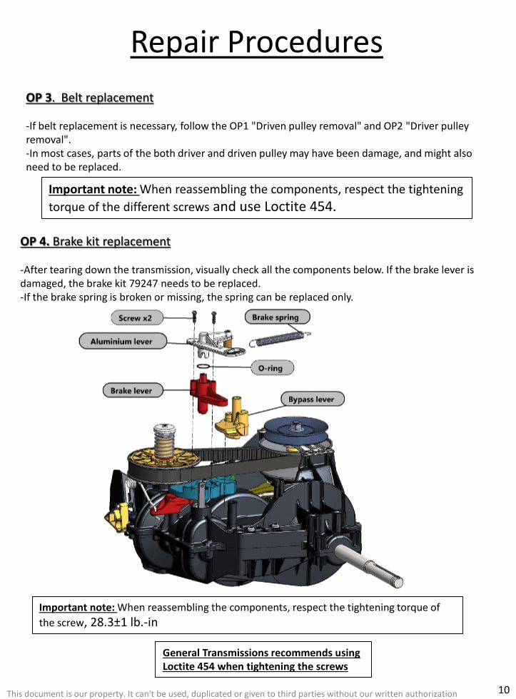
OP 4. Brake kit replacement
-After tearing down the transmission, visually check all the components below. If the brake lever is damaged, the brake kit 79247 needs to be replaced.-If the brake spring is broken or missing, the spring can be replaced only.
10
Important note: When reassembling the components, respect the tightening torque of the screw, 28.3±1 lb.-in
General Transmissions recommends using Loctite 454 when tightening the screws

Repair Procedures
This document is our property. It can't be used, duplicated or given to third parties without our written authorization
-To remove the brake lever, separate and hold the 2 strips of the lever, to release the two studs and allow the lever removing.
11
-It is necessary to rotate the shift came to the reverse position, for removing the brake and bypass levers.

Repair Procedures
This document is our property. It can't be used, duplicated or given to third parties without our written authorization
OP 5. Cam replacement
12
Important note: When reassembling the components, respect the tightening torque of the screws, 19.5±1 lb.-in
General Transmissions recommends using Loctite 454 when tightening the screws
Shift cam
WasherScrew

This document is our property. It can't be used, duplicated or given to third parties without our written authorization
Repair Procedures
-To install a new inversion rod:1- Insert the rod in the inversion fork lever.2- Insert the rod in the inversion lever.3- Install the inversion lever on the transmission.
13
OP 6. Inversion kit replacement-First remove the inversion lever from the upper case, then remove the spring from the fork lever.

This document is our property. It can't be used, duplicated or given to third parties without our written authorization
Repair ProceduresOP 7. Variation kit replacement
- First remove the wire rod, to be able to remove the control lever and variation parts.- The 5 parts are available in the variation kit.
-When putting back the components on the transmission, make sure that the both variation levers are correctly seated, and the wire rod properly inserted.
14

Exploded View
This document is our property. It can't be used, duplicated or given to third parties without our written authorization 15

Driver kit exploded viewGT79398
This document is our property. It can't be used, duplicated or given to third parties without our written authorization 16
Ramp pin
Fixed ramp
Driver support
Cover
Driver shaft
Fixed flange
Screw x3
Screw x4
Nut
Spring
Mobile flange
Bearing
Pulley spacer x2
Bearing
Spacer
Main pulley flange
Control bushing

Driven kit exploded viewGT79244
This document is our property. It can't be used, duplicated or given to third parties without our written authorization 17

Variation kit exploded viewGT79362
This document is our property. It can't be used, duplicated or given to third parties without our written authorization 18
Brake kit exploded viewGT79247

Shift came exploded viewGT79246
This document is our property. It can't be used, duplicated or given to third parties without our written authorization 19
Inversion control exploded viewGT79263

Compression limiters GT79264 (6 per package)
This document is our property. It can't be used, duplicated or given to third parties without our written authorization 20
Belt GT79267
Hardware kit GT79265- 6 screws 5x16, also included in the driver kit (4) and the brake kit (2).
- 1 screw 4x16 and 1 washer, also included in the shift cam kit.
- 1 screw 4x16 and 1 spring washer, also included in the driven kit.
Cover GT38808

Notes
………………………………………………………………………………………………………
………………………………………………………………………………………………………
………………………………………………………………………………………………………
………………………………………………………………………………………………………
………………………………………………………………………………………………………
………………………………………………………………………………………………………
………………………………………………………………………………………………………
………………………………………………………………………………………………………
………………………………………………………………………………………………………
………………………………………………………………………………………………………
………………………………………………………………………………………………………
………………………………………………………………………………………………………
……………………………………………………………………
This document is our property. It can't be used, duplicated or given to third parties without our written authorization 21

Drive solutions for outdoor power equipment
General TransmissionsBP 317 – ZI du Bois Joly Sud 2, Rue Johannes Gutemberg85503 Les Herbiers Cedex France
General Transmissions ChinaGeneral Transmissions (Suzhou)82 Ping Sheng Lu, SIPSuzhou, 215126 P.R.China
General Transmissions inc.302 Lorenaly Drive, Suite EBrownsville, TX 78526USA
General Transmissions inc.27351 Spectrum wayOak Ridge North, TX 77385USA
www.generaltransmissions.comThis document is our property. It can't be used, duplicated or given to third parties without our written authorization
After Sales Service contact :[email protected]
Watch our service videos on the General Transmissions website