sharpirrangefinder&(gp2d12,gp2d120)& -...
TRANSCRIPT

Sharp IR Range Finder (GP2D12,GP2D120) Theory: Infrared light is transmitted and then reflected back from an object. Based on the angle of reflection, the sensor can figure out distance to that object. Equations for calculating range(in cm) from Voltage: Volts = 5/1024*Analog_Reading. GP2D12: Range = (6787 / (Volts -‐ 3)) – 4 GP2D120: Range = (2914 / (Volts + 5)) – 1 Datasheets GP2D12 http://www.sharpsma.com/webfm_send/1203 GP2D120 http://www.sharpsma.com/webfm_send/1205 Links Choosing IR Sensor http://www.acroname.com/robotics/info/articles/ sharp/sharp.html#e8 Sharp IR Theory http://www.societyofrobots.com/sensors_sharpirrange.shtml Obstacle Avoiding Car https://wiki.engr.illinois.edu/display/ae498mpa/ The+Sharp+GP2D12+Infrared+Range+Finder Arduino Tutorial http://luckylarry.co.uk/arduino-‐projects/arduino-‐using-‐a-‐sharp-‐ir-‐sensor-‐for-‐distance-‐calculation/ Robot using IR Rangefinder http://bunedoggle.com/robots.php Sample Code //Rangefinder on Pin #1 int IRpin = 1; void setup() { pinMode(IRpin,INPUT); Serial.begin(9600); } void loop() { int volts = analogRead(IRpin); int distance = (6787 / (volts -‐ 3)) – 4; Serial.println(distance); delay(100); //100mS delay }
Specs: Supply Voltage: 4.5V to 5.5V Supply Current: 33 to 50 mA Output: Analog Voltage Detection Range: 10cm to 80cm(GP2D12) 4cm to 30cm(GP2D120)
Common Problems and Resolutions
1. Don’t use in direct or indirect sunlight
2. Don’t use reflective objects 3. Be sure to be within the acceptable
range 4. The linear equations don’t work
below/above the detection range 5. Wait at least 40mS before reading
the same sensor again Circuit

PING Ultrasonic Sensor Theory: Ultrasonic sound is emitted and then the sensor waits for the sound to bounce back from an object. The total round trip time translates into distance, since the speed of sound is known. To transmit ultrasonic sound, send a 2 µS high pulse. Equation for calculating range(in cm) from duration of round trip Range = Round_trip/ 29 / 2 Datasheets http://www.parallax.com/Portals/0/Downloads /docs/prod/acc/28015-‐PING-‐v1.6.pdf Links Ping Ultrasonic Tutorial http://arduino.cc/en/Tutorial/Ping? from=Tutorial.UltrasoundSensor Sonar Theremin http://alandtech.blogspot.com/2007/12/arduino-‐theremin.html RumbleBot http://dinofab.com/rumblebot.html Make an Obstacle Avoiding Robot http://www.instructables.com/id/How-‐to-‐Make-‐an-‐Obstacles-‐Avoiding-‐Robot-‐Arduino-‐S/ Sample Code //Sonar on Pin #7 const int pingPin = 7; long duration, cm; pinMode(pingPin, OUTPUT); digitalWrite(pingPin, LOW); delayMicroseconds(2); digitalWrite(pingPin, HIGH); delayMicroseconds(5); digitalWrite(pingPin, LOW); pinMode(pingPin, INPUT); duration = pulseIn(pingPin, HIGH); cm = duration/29/2; // 29 µS/ cm
Specs: Supply Voltage: 4.5V to 5.5V Supply Current: 30 to 35 mA Output: Digital Pulse Detection Range: 2cm to 300cm
Common Problems and Resolutions
1. Temperature affects the speed of sound. Take it into account if you want a lot of accuracy.
2. Avoid foam objects( they absorb sound waves)
3. Be sure to be within the acceptable range
4. The linear equations don’t work below/above the detection range
5. Avoid using multiple sonars at the same exact moment (sound intereference)
Circuit

Switch Theory: Pushing or sliding closes the switch and short circuits the two sides of the switch to each other. Also known as a momentary switch. Use a 10k resistor for pullup or pulldown. 50mS should be a good value for debouncing. IMPORTANT: Read this -‐ http://www.arduino.cc/en/Tutorial/Debounce Datasheets http://www.parallax.com/Portals/0/Downloads /docs/prod/acc/28015-‐PING-‐v1.6.pdf Links Pushbutton Tutorial http://www.arduino.cc/en/Tutorial/Pushbutton Slideswitch Tutorial http://www.arduino.cc/en/Tutorial/Switch Mothbot http://www.instructables.com/id/The-‐Arduino-‐Mothbot/ Sample Code int ledPin = 13; int inPin = 7; int val = 0; void setup() { pinMode(ledPin, OUTPUT); pinMode(inPin, INPUT); } void loop(){ val = digitalRead(inPin); if (val == LOW) digitalWrite(ledPin, LOW); // LED OFF } else { digitalWrite(ledPin, HIGH); //LED ON } }
Specs:
Common Problems and Resolutions
1. Debouncing is a major issue 2. Be sure to use a pulldown or pullup
resistor to avoid floating 3. Be sure to stay within your switch’s
electrical limits 4. Remember to declare the switch’s
pin as an input 5. Know whether your switch is High
when closed or when open. Circuit

Potentiometer Theory: Sliding or rotating a potentiometer changes the resistance at the output pins. By inputting voltage and treating the potentiometer (or pot) as a voltage divider Note: Some potentiometers have a linear relationship between resistance and position, others do not! Datasheets Links Potentiometer Tutorial http://www.arduino.cc/en/Tutorial/Potentiometer Analog Input Tutorial http://www.arduino.cc/en/Tutorial/AnalogInput DC Motor Control With a Pot http://luckylarry.co.uk/arduino-‐projects/arduino-‐control-‐a-‐dc-‐motor-‐with-‐potentiometer-‐and-‐multiple-‐power-‐supplies/ LED Control with a Pot http://www.instructables.com/id/arduino-‐control-‐leds-‐with-‐a-‐pot-‐meter/ Sample Code // Potentiometer connected to Pin #2 int val = 0; int potPin = 2; pinMode(potPin, INPUT); val = analogRead(potPin);
Specs: Supply Voltage: 5V
Common Problems and Resolutions
1. Many pots do not have a linear relationship
2. Remember to set the potentiometer pin as an Input
3. Don’t forget to connect all the pins of the pot
Circuit

Accelerometer(ADXL335) Theory: Tiny mechanical pieces inside the sensor react to acceleration. The acceleration vector felt on the sensor is separated into X, Y, and Z components. Each component is outputted on its respective channel, in Analog Voltage format. Accelerometers pick up all accelerations, including gravity. Taking into account all components can provide you with a tilt measurement. Datasheets ADXL335 http://www.sparkfun.com/datasheets/Components/ SMD/adxl335.pdf Links Theory http://www.societyofrobots.com/ sensors_accelerometer.shtml ADXL335 Tutorial http://www.arduino.cc/en/Tutorial/ADXL3xx 3D Cube http://www.pyrofersprojects.com/3dcube.php Sample Code // Accelerometer connected to pins A3, A2, A1. const int xpin = A3; const int ypin = A2; const int zpin = A1; xval = analogRead(xpin); yval = analogRead(ypin); zval = analogRead(zpin); delay(100);
Specs: Supply Voltage: ADXL335 1.8V to 3.6V Supply Current: 320uA Output: Analog Voltage Detection Range: 3 axis, +-‐3g(ADXL335)
Common Problems and Resolutions
1. Stay within the voltage supply range! 2. DO NOT POWER WITH 5V! (Use 3.3V) 3. It measures acceleration, you can use it
for tilt ONLY assuming your object doesn’t accelerate
Circuit

LED Theory: Pass voltage and current through an LED and it lights up. Most common LEDs draw 20mA nominally. They have a forward voltage of 1.2V, which means they have a 1.2V drop. (Driving Voltage – Forward Voltage)/LED current = resistor value to use Resistor value does not have to be precise. For example, if you calculate a 364 ohm resistor, just go ahead and use a 220 ohm or 330 ohm or 470 ohm, doesn’t quite matter. Datasheets Links Blink LED Tutorial http://www.arduino.cc/en/Tutorial/Blink LED Tutorial http://www.societyofrobots.com/ electronics_led_tutorial.shtml Sample Code //LED on Pin #13 void setup() { pinMode(13, OUTPUT); } void loop() { digitalWrite(13, HIGH); // High delay(1000); digitalWrite(13, LOW); // Low delay(1000); }
Specs: Supply Voltage: 2V to 20V Supply Current: 20 to 25 mA Output: Visible Light
Common Problems and Resolutions
1. Don’t connect the LED backwards 2. Be sure to use a resistor! 3. Be sure to be within the acceptable
range 4. Be sure to set the pin as an output
Circuit

Piezo Sensor Theory: Basically, a really low power , crude microphone. Force or vibration on the piezo sensor generates voltage. Datasheets Links Arduino Tutorial http://www.arduino.cc/en/Tutorial/KnockSensor Piezo Effect Theory http://www.aurelienr.com/electronique/piezo/piezo.pdf Sample Code int ledPin = 13; int knockSensor = 0; byte val = 0; int THRESHOLD = 100; void setup() { pinMode(ledPin, OUTPUT); beginSerial(9600); } void loop() { val = analogRead(knockSensor); if (val >= THRESHOLD) { digitalWrite(ledPin,HIGH);//LED On printString("Knock!"); } delay(100); //delay }
Specs: Supply Voltage: 5V Supply Current: 5mA Output: Analog Voltage Detection Range:
Common Problems and Resolutions
1. Don’t forget the 1 megaohm resistor
2. Certain piezos aren’t sensitive to weak vibrations
Circuit

Piezo Beeper Theory: Applying electricity creates vibration of the piezoelectric plates, producing sound. Give it different frequencies to produce specific sounds, and even music. Datasheets Links Play Melody Arduino http://www.arduino.cc/en/Tutorial/PlayMelody Melody Theory http://arduino.cc/en/Tutorial/Melody Spooky Sound Project http://todbot.com/blog/2006/10/29/spooky-‐arduino-‐projects-‐4-‐and-‐musical-‐arduino/ Getting Started with Arduino http://tronixstuff.wordpress.com/2010/07/24/getting-‐started-‐with-‐arduino-‐–-‐chapter%C2%A0thirteen/ Sample Code // Generates a 1500 Hz sound void setup() { pinMode(11, OUTPUT); // sets the pin as output } void loop() { analogWrite(11,128); // 50% on delay(500); digitalWrite(11, LOW); delay(500); }
Specs: Supply Voltage: Hobby 3V – 12V Supply Current: 20mA Output: Sound
Common Problems and Resolutions
1. Stay within the voltage supply range!
2. Make sure you’re actually transmitting in the audible human hearing range
Circuit

XBee Theory: All the encoding and reliable wireless communication work is done onboard the Xbee. It’s a serial gateway that allows you to transmit UART seamlessly from one device to another (or from device to computer). NOTE: Remember to set the Xbee firmwares before use Datasheets XBee /Xbee Pro http://ftp1.digi.com/support/documentation/ 90000976_H.pdf Links Common Xbee Problems http://www.faludi.com/projects/common-‐xbee-‐mistakes/ Connecting Xbee to Arduino http://answers.oreilly.com/topic/2458-‐how-‐to-‐connect-‐an-‐arduino-‐to-‐an-‐xbee-‐radio/ Using the Shield http://www.arduino.cc/en/Main/ArduinoXbeeShield Networked On-‐Air Light http://makeprojects.com/Project/Networked-‐On-‐Air-‐Light/614/1 Xbee Basics http://forums.trossenrobotics.com/tutorials/how-‐to-‐diy-‐128/xbee-‐basics-‐3259/ Programming Arduino Wirelessly http://www.faludi.com/itp_coursework/meshnetworking/ XBee/XBee_program_Arduino_wireless.html Sample Code int myData = 0; // define the byte void setup(){. Serial.begin(38400); } void loop(){ myData = Serial.read(); // read serial byte Serial.print(myData + 1, BYTE); // reply what we received + 1 }
Specs: Supply Voltage: Direct 3.3V Xbee Shield 5V Supply Current: 50mA Output: UART serial Range: 1mW 300ft 60mW 1 mile
Common Problems and Resolutions
1. Stay within the voltage supply range!
2. Use an Xbee shield or voltage shifter! The Xbee cannot handle 5V level serial directly
3. Be sure to program the correct firmware to each device.
4. Be sure to match baud rates 5. No flow control and no
handshaking on the computer side of things
Circuit

BlueSMIRF Theory: Basically a Bluetooth Xbee. Serial gateway using Bluetooth as the wireless protocol. Note: All signal pins are 3.3V to 6V tolerant, so you can connect directly to Arduino Datasheets http://www.rovingnetworks.com/documents/RN-‐41.pdf Links BlueSMIRF Tutorial http://www.sparkfun.com/tutorials/67 Setting up BlueSMIRF http://inst.eecs.berkeley.edu/~ee192/sp11/design/ abe_setup_bluesmirf.pdf Automatic Cat Feeder http://www.damonkohler.com/2010/11/android-‐automated-‐cat-‐feeder.html Linux and Arduino Bluetooth Link http://www.flickr.com/photos/ ricardo_ferreira/4225911933/ Sample Code int myData = 0; // define the byte void setup(){. Serial.begin(38400); } void loop(){ myData = Serial.read(); // read serial byte Serial.print(myData + 1, BYTE); // reply what we received + 1 }
Specs: Supply Voltage: Silver/Gold 3.3V – 6V Supply Current: 25mA Output: UART Wireless Range: Gold 100m Silver 18m
Common Problems and Resolutions
1. Stay within the voltage supply range! 2. Be sure to match up baud rates 3. Stay within the wireless range 4. Be sure to short RTS and CTS if
you’re not using flow control 5. No flow control and no handshaking
on the computer side of things Circuit

GPS Module Theory: GPS receiver listens to satellites and calculates its position on earth in terms of latitude and longitude. Outputs its position in serial data in multiple forms of sentences every second or so. Since it relies on radio frequency, it won’t work inside metallic enclosures well and needs a somewhat clear view of the sky. Datasheets GPS Module http://www.parallax.com/Portals/0/Downloads/ docs/prod/acc/GPSSensorDatasheetV2.0.pdf Links GPS Tutorial http://www.arduino.cc/playground/Tutorials/GPS GPS Sentences List http://www.kh-‐gps.de/nmea-‐faq.htm Arduino GPS System http://www.seancarney.ca/projects/arduino-‐gps-‐receiver/arduino-‐gps-‐system Another GPS system http://letsmakerobots.com/node/5972 Sample Code Very different ways of implementing, depending on hardware and what sentences it outputs. Read this: http://www.arduino.cc/playground/Tutorials/GPS
Specs: Supply Voltage: 3V – 5V Supply Current: 40mA Output: UART Baud Rate: 4800(usually) or 9600
Common Problems and Resolutions
1. Stay within the voltage supply range! 2. If using a module directly: Do not
transmit 5V on the GPS’s line, but you can receive the GPS’s output on your 5V AVR line. If you’re using a Shield or Parallax’s GPS – just direct connect.
3. Check the datasheet to see what baud rate its transmitting on(usually 4800)
Circuit
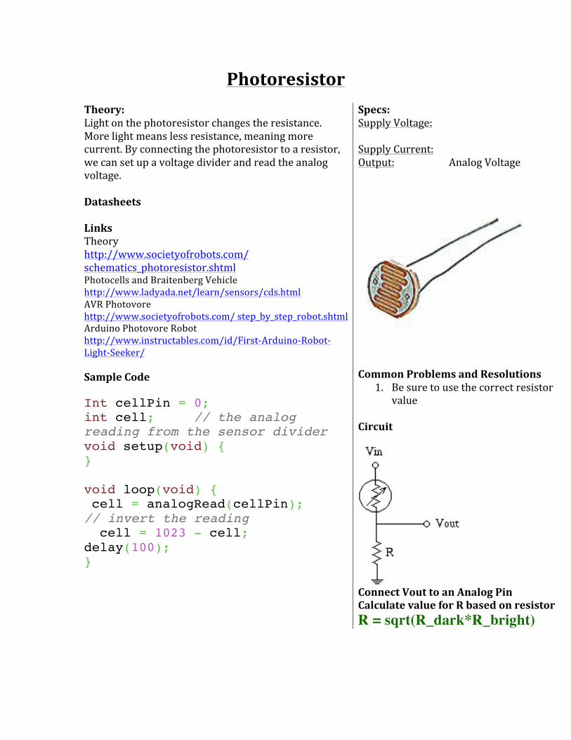
Photoresistor Theory: Light on the photoresistor changes the resistance. More light means less resistance, meaning more current. By connecting the photoresistor to a resistor, we can set up a voltage divider and read the analog voltage. Datasheets Links Theory http://www.societyofrobots.com/ schematics_photoresistor.shtml Photocells and Braitenberg Vehicle http://www.ladyada.net/learn/sensors/cds.html AVR Photovore http://www.societyofrobots.com/ step_by_step_robot.shtml Arduino Photovore Robot http://www.instructables.com/id/First-‐Arduino-‐Robot-‐Light-‐Seeker/ Sample Code Int cellPin = 0; int cell; // the analog reading from the sensor divider void setup(void) { } void loop(void) { cell = analogRead(cellPin); // invert the reading cell = 1023 - cell; delay(100); }
Specs: Supply Voltage: Supply Current: Output: Analog Voltage
Common Problems and Resolutions
1. Be sure to use the correct resistor value
Circuit
Connect Vout to an Analog Pin Calculate value for R based on resistor R = sqrt(R_dark*R_bright)

Infrared Phototransistor Theory: Basically a transistor whose base is triggered by incident infrared light. Infrared light hitting the phototransistor switches the transistor on, allowing current to pass through. Varying light intensity and frequencies cause the phototransistor to output an analog voltage. Note: The emitter ( e) side of the phototransistor is notched. If your phototransistor has 3 pins, connect the center pin to ground, and Datasheets http://www.fairchildsemi.com/ds/QS/QSD123.pdf Links Connecting to Arduino http://sites.google.com/site/therobotronics/ arduino/connect-‐a-‐phototransistor-‐to-‐arduino Using an Infrared Phototransistor http://www.instructables.com/id/Use-‐an-‐infrared-‐phototransistor/ Interfacing to an Infrared Remote Control http://www.arduino.cc/playground/Code/ InfraredReceivers More Infrared Remote Interfacing http://www.ladyada.net/learn/sensors/ir.html http://www.pyrofersprojects.com/3dcube.php Sample Code (same as phototransistor) Int cellPin = 0; int cell; // the analog reading from the sensor divider void setup(void) { } void loop(void) { cell = analogRead(cellPin); // invert the reading cell = 1023 - cell; delay(100);
Specs: Supply Voltage: 0-‐30V Supply Current: Output: Analog Voltage Frequency Response: Check Part’s Datasheet
Common Problems and Resolutions
1. Stay within the voltage supply range! 2. Do not use in sunlight. 3. Be sure to connect the
phototransistor the right way Circuit

Serial LCD Theory: LCD that is usually controlled using parallel pins has a microcontroller on board that converts the serial input of an Arduino(or other microcontroller) to the parallel signals. Datasheets Sparkfun Serial LCD http://www.sparkfun.com/datasheets/ LCD/SerLCD_V2_5.PDF Links Serial LCD Tutorial http://www.arduino.cc/playground/ Learning/SerialLCD Sparkfun’s Serial LCD http://www.arduino.cc/playground/Learning/ SparkFunSerLCD http://www.societyofrobots.com/ sensors_accelerometer.shtml ADXL335 Tutorial http://www.arduino.cc/en/Tutorial/ADXL3xx 3D Cube http://www.pyrofersprojects.com/3dcube.php Sample Code // Connect LCD to Arduino’s UART void loop() { //backlightOn(0); // turn the backlight on all the time clearLCD(); Serial.print(" Hello"); newLine(); Serial.print("Arduino"); delay(5000); // delay 5 seconds } void clearLCD(){ Serial.print(12, BYTE); } void newLine() { Serial.print(10, BYTE);
Specs: Supply Voltage: ADXL335 1.8V to 3.6V Supply Current: 320uA Output: Analog Voltage Detection Range: 3 axis, +-‐3g(ADXL335)
Common Problems and Resolutions
1. Stay within the voltage supply range! 2. Be sure to match baud rates 3. Be sure to connect the Serial output of
the Arduino to the Serial input of LCD Circuit
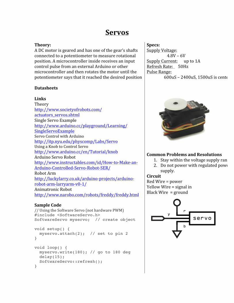
Servos Theory: A DC motor is geared and has one of the gear’s shafts connected to a potentiometer to measure rotational position. A microcontroller inside receives an input control pulse from an external Arduino or other microcontroller and then rotates the motor until the potentiometer says that it reached the desired position Datasheets Links Theory http://www.societyofrobots.com/ actuators_servos.shtml Single Servo Example http://www.arduino.cc/playground/Learning/ SingleServoExample Servo Control with Arduino http://itp.nyu.edu/physcomp/Labs/Servo Using a Knob to Control Servo http://www.arduino.cc/en/Tutorial/knob Arduino Servo Robot http://www.instructables.com/id/How-‐to-‐Make-‐an-‐Arduino-‐Controlled-‐Servo-‐Robot-‐SER/ Robot Arm http://luckylarry.co.uk/arduino-‐projects/arduino-‐robot-‐arm-‐larryarm-‐v0-‐1/ Animatronic Robot http://www.narobo.com/robots/freddy/freddy.html Sample Code // Using the Software Servo (not hardware PWM) #include <SoftwareServo.h> SoftwareServo myservo; // create object void setup() { myservo.attach(2); // set to pin 2 } void loop() { myservo.write(180); // go to 180 deg delay(15); SoftwareServo::refresh(); }
Specs: Supply Voltage: 4.8V – 6V Supply Current: up to 1A Refresh Rate: 50Hz Pulse Range: 600uS – 2400uS, 1500uS is center
Common Problems and Resolutions
1. Stay within the voltage supply range! 2. Do not power with regulated power
supply. Circuit Red Wire = power Yellow Wire = signal in Black Wire = ground

Modified Servos Theory: A servo that has been tricked into thinking its always at the center point( either by gluing the potentiometer to the center or replacing it with a voltage divider). Instead of rotating to specific angles, instead it now rotates at different speeds. For example, if a pulse is sent to go at -‐90 degrees from center, the servo will constantly turn the motor very quickly ( because the potentiometer will never reach that 90 degrees point). Datasheets Links Guide http://www.acroname.com/robotics/info/ ideas/continuous/continuous.html Tips for Modifying Servos http://narobo.com/articles/ModServos.html Continuous Rotation Servo Robot http://bunedoggle.com/robots.php Sample Code // Using the Software Servo (not hardware PWM) #include <SoftwareServo.h> SoftwareServo myservo; // create object void setup() { myservo.attach(2); // set to pin 2 } void loop() { myservo.write(180); // go to 180 deg delay(15); SoftwareServo::refresh(); }
Specs: Supply Voltage: 4.8V – 6V Supply Current: up to 1A Refresh Rate: 50Hz Pulse Range: 600uS is slowest, 1500uS is stop, 2400us is fastest
Common Problems and Resolutions
1. Use precision(1%) resistors for the voltage divider trick
2. Stay within voltage range 3. Don’t break gears when modifying 4. Avoid powering from regulated
power supply Circuit

Wheeled DC Motor (GM Series) Theory: Applying voltage and current to a motor makes it spin one way. Changing the polarity of the voltage makes it spin the other direction. Use this to make a wheeled robot that uses a DC motor. Note: Use a Transistor, MOSFET, or Motor controller. Datasheets Links Buy Wheel + Motor combo http://solarbotics.com/products/gmpw_deal/ List of motors – Go Through Specs to See Current and Torque requirements http://solarbotics.com/motors_accessories/ gear_motors/ Gear motor tutorial http://www.societyofrobots.com/ actuators_dcmotors.shtml Gears Tutorial http://www.societyofrobots.com/ mechanics_gears.shtml Sample Code
Specs: Supply Voltage: Supply Current: Output:
Common Problems and Resolutions
1. Stay within the voltage supply range! 2. DO NOT power directly from
microcontroller pins Circuit
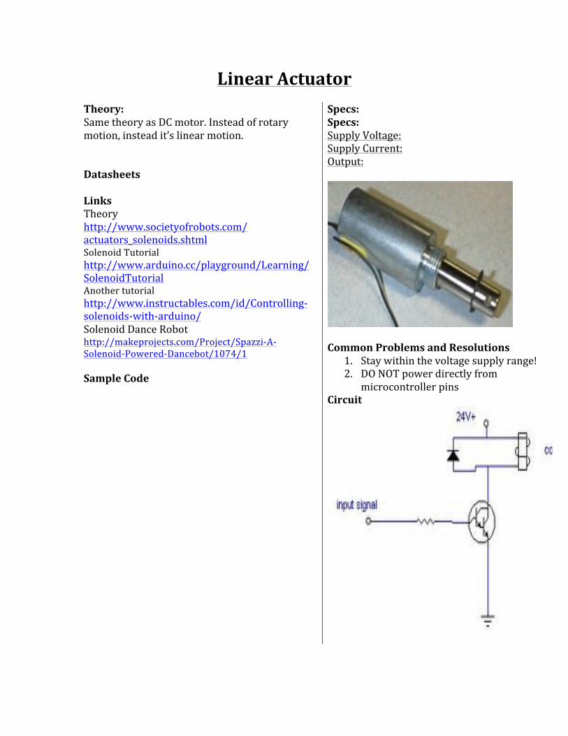
Linear Actuator Theory: Same theory as DC motor. Instead of rotary motion, instead it’s linear motion. Datasheets Links Theory http://www.societyofrobots.com/ actuators_solenoids.shtml Solenoid Tutorial http://www.arduino.cc/playground/Learning/ SolenoidTutorial Another tutorial http://www.instructables.com/id/Controlling-‐solenoids-‐with-‐arduino/ Solenoid Dance Robot http://makeprojects.com/Project/Spazzi-‐A-‐Solenoid-‐Powered-‐Dancebot/1074/1 Sample Code
Specs: Specs: Supply Voltage: Supply Current: Output:
Common Problems and Resolutions
1. Stay within the voltage supply range! 2. DO NOT power directly from
microcontroller pins Circuit

Muscle Wire Theory: Datasheets Links Muscle Wire Actuator http://www.instructables.com/id/Screen-‐Saver-‐Defeater/step3/Make-‐the-‐Nitinol-‐actuator/ Actuator Example http://www.rr-‐cirkits.com/actuator.html Muscle Wire Arm Example http://talkingelectronics.com/projects/Nitinol/Nitinol-‐1.html Sample Code
Specs: Supply Voltage: Supply Current: Output:
Common Problems and Resolutions
1. Stay within the voltage supply range!
Circuit

Relay Theory: Current flowing through the relay coil, pulls in and closes a switch using magnetic force. Datasheets Links Theory http://www.kpsec.freeuk.com/components/relay.htm Using Relays to Control Lights http://www.glacialwanderer.com/hobbyrobotics/?p=9 Arduino Nerf Gun http://blog.makezine.com/archive/2010/05/arduino-‐nerf-‐sentry-‐gun-‐build-‐relay.html 12V Relay to Arduino Tutorial http://www.instructables.com/id/Connecting-‐a-‐12V-‐Relay-‐to-‐Arduino/ Sample Code
Specs: Supply Voltage: Supply Current: Output:
Common Problems and Resolutions
1. Stay within the voltage supply range! 2. Stay within the current limits
Circuit

Transistor Theory: A small current at the base, allows a larger current to flow between the emitter and the source For a NPN transistor, it’s a positive voltage at the base allows a larger current to flow. For a PNP transistor, it’s a negative voltage at the base allows a larger current to flow. Datasheets Links Transistor Tutorial(READ THIS!) http://www.kpsec.freeuk.com/trancirc.htm Arduino Motor Control with Transistor http://www.instructables.com/id/Use-‐Arduino-‐with-‐TIP120-‐transistor-‐to-‐control-‐moto/ Using a transistor as a Switch http://www.electronics-‐tutorials.ws/transistor/tran_4.html Sample Code
Specs:
Common Problems and Resolutions
1. Stay within the voltage and current supply range!
Circuit
