sketch - seismic report
DESCRIPTION
111TRANSCRIPT

7/18/2019 Sketch - Seismic Report
http://slidepdf.com/reader/full/sketch-seismic-report 1/106

7/18/2019 Sketch - Seismic Report
http://slidepdf.com/reader/full/sketch-seismic-report 2/106
Landspitali hospital seismic a
Bedward
Treatment
Day patient

7/18/2019 Sketch - Seismic Report
http://slidepdf.com/reader/full/sketch-seismic-report 3/106
REPORT
Report nr.: Project nr.: Dato:
1 333582 26. 1
Client:
.
Landspitali hospital conceptual seismic analy
Summary:
.

7/18/2019 Sketch - Seismic Report
http://slidepdf.com/reader/full/sketch-seismic-report 4/106
Content:
1 ...................................................................Introduction2 ......................................................................Summary
3
.................................Basis for design and calculations3.1
..............................................................................Introduction
3.2
..............................................Horizontal load resisting system
3.2.1 ..................................................Ductile wall characteristics
3.2.2 ......................................................Location of ductile walls
3.3 ...................................................Response Spectrum Method
3.3.1
................................................................ Analysis software3.3.2 .............................................................................Modelling
3.3.3
........................................................Loads and load factors
3.3.4 .............................................Materials and material factors
3.4
..........................................................................Seismic action
3.4.1 .....................................................................................PGA
3.4.2
..................................................Elastic response spectrum3.4.3 ....................................................................Load directions
3.4.4
..................................................................Behaviour factor
3.4.5 .................................................................Importance class
3.5
..........................................................................Design criteria
3.5.1
.....................................................................P-Delta effects
3.5.2
...............................................Limitation of inter-storey drift
3.5.3
.......................................................Limitation of axial loads4 ..........................................................................Results
4.1 ..............................................................................Introduction
4.2 ...........................................................Maximum deformations
4.2.1 .......................................................Bed ward deformations
4.2.2
......................................................Treatment deformations
4.2.3
....................................................Day patient deformations
4.3 ..............................................................Maximum axial stress
4.3.1
..........................................Bed ward structural walls stress
4 3 2 T t t t t l ll t

7/18/2019 Sketch - Seismic Report
http://slidepdf.com/reader/full/sketch-seismic-report 5/106
Appendix:
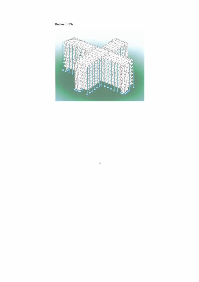
Appendix A Bed ward
Appendix B Treatment Appendix C Day patient
Appendix D Veri ficat ion by hand calculat ions

7/18/2019 Sketch - Seismic Report
http://slidepdf.com/reader/full/sketch-seismic-report 6/106
1 Introduction
A conceptual seismic design has been carried out for the new LaHospital located in Reykjavik, Iceland.
The main objective with this work has been to choose a robust lasystem which complies with safety requirements in Eurocode 8 /
The following buildings are treated in this report:
• Bed ward• Treatment• Day patient
The building geometries have been modelled in a 3D finite elemeresponse spectrum analyses have been performed. The finite elbeen verified by hand calculations using a simplified method /2/.
All structural walls designed for seismic forces are assumed fixesuitable anchoring. Foundations are assumed to be continuous uinvestigated buildings ensuring a well distributed action from thebuildings.
2 Summary
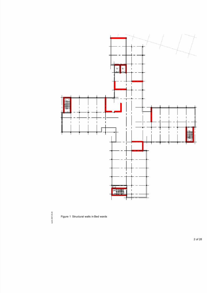
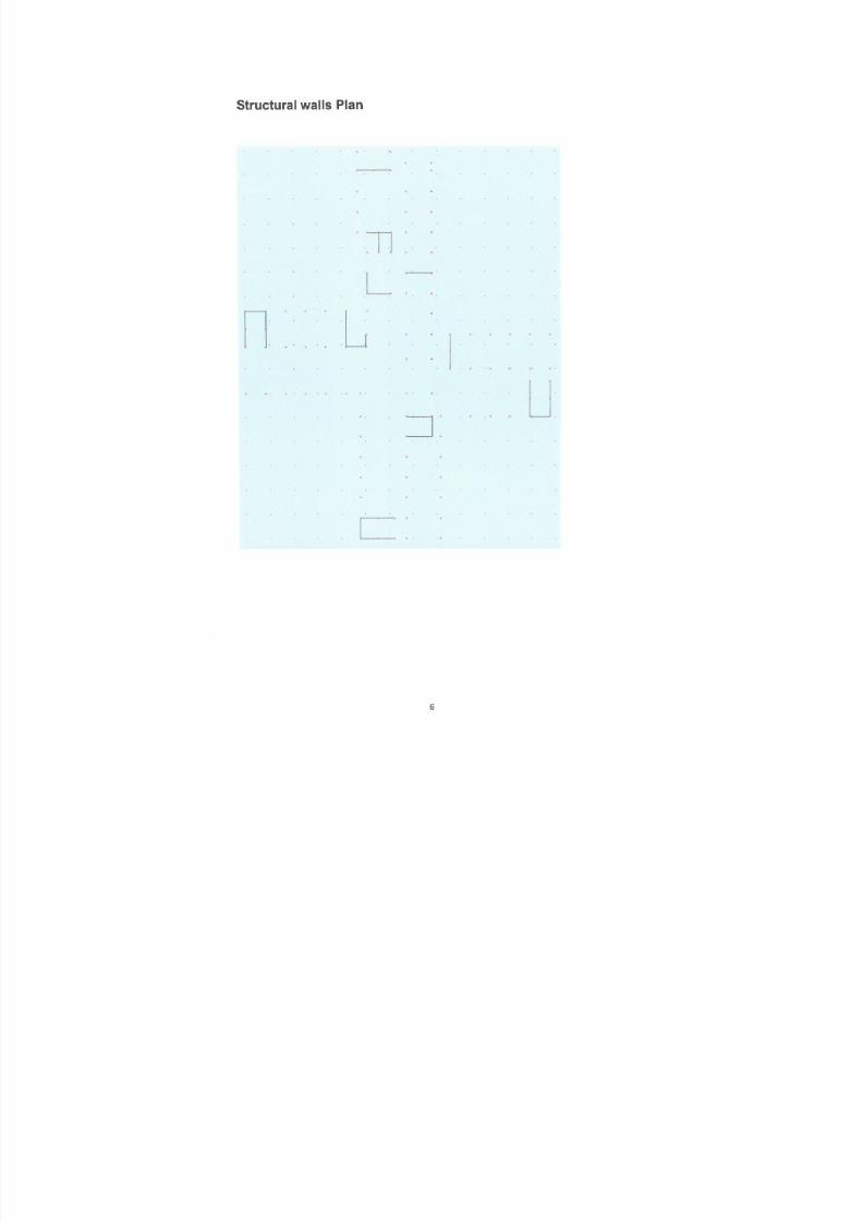
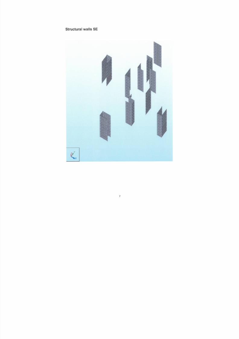
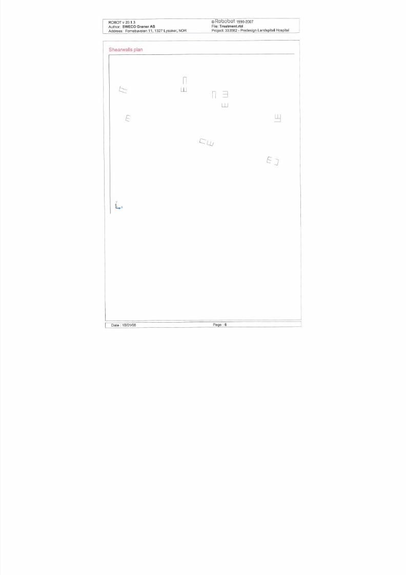
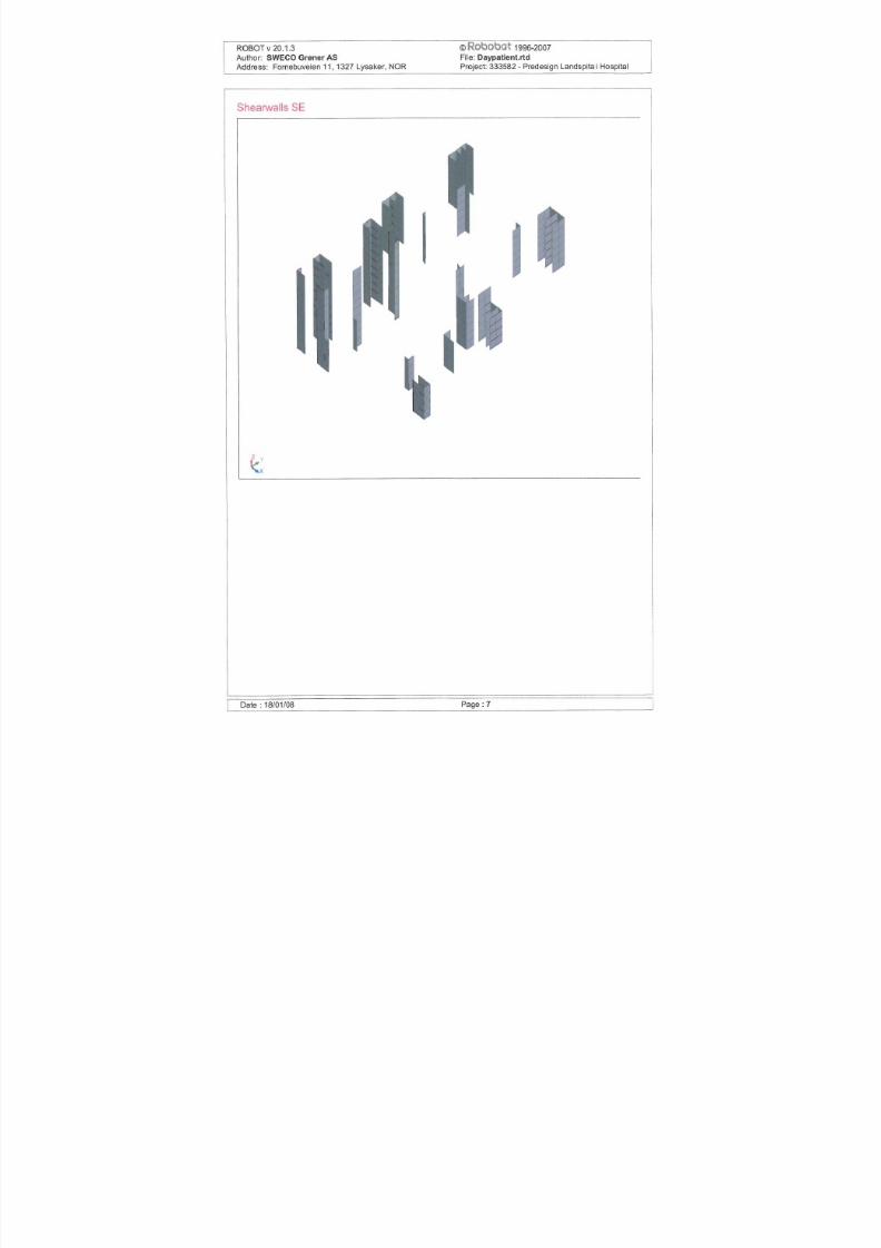
A lateral force resisting system with ductile concrete structural winvestigated. The structural walls in the different buildings invest
with thick red lines in Figure 1, Figure 2 and Figure 3. Calculatiolayout show deformations and concrete stress which are accepta
7/18/2019 Sketch - Seismic Report
http://slidepdf.com/reader/full/sketch-seismic-report 7/106

7/18/2019 Sketch - Seismic Report
http://slidepdf.com/reader/full/sketch-seismic-report 8/106

7/18/2019 Sketch - Seismic Report
http://slidepdf.com/reader/full/sketch-seismic-report 9/106
7/18/2019 Sketch - Seismic Report
http://slidepdf.com/reader/full/sketch-seismic-report 10/106
3 Basis for design and calculations
3.1 Introduction
Basis for the design is Eurocode 8, EN1998-1-December 2004. short form when referred to in this document.
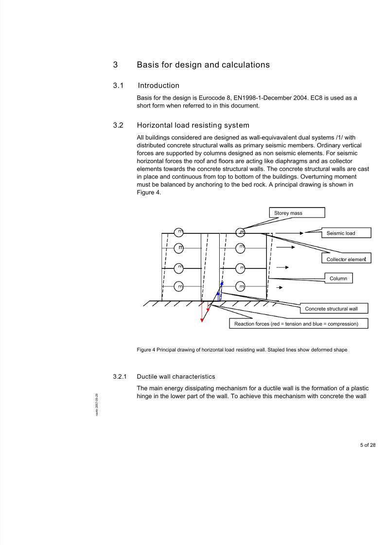
3.2 Horizontal load resisting system
All buildings considered are designed as wall-equivavalent dual distributed concrete structural walls as primary seismic membersforces are supported by columns designed as non seismic elemhorizontal forces the roof and floors are acting like diaphragms aelements towards the concrete structural walls. The concrete str
in place and continuous from top to bottom of the buildings. Ovemust be balanced by anchoring to the bed rock. A principal drawFigure 4.
m
m
Storey mass
Co
Reaction forces (red = tension and
7/18/2019 Sketch - Seismic Report
http://slidepdf.com/reader/full/sketch-seismic-report 11/106
is designed such that yielding in the reinforcement on the tensioconcrete cracks in compression on the compression side.
3.2.2 Location of ducti le walls
The location of the concrete structural walls is primarily around sand electrical shafts. Concrete structural walls are if possible plaperimeter of the building to avoid torsion modes. Additional walls
necessary by the analysis. Effort is made to meet architectural d
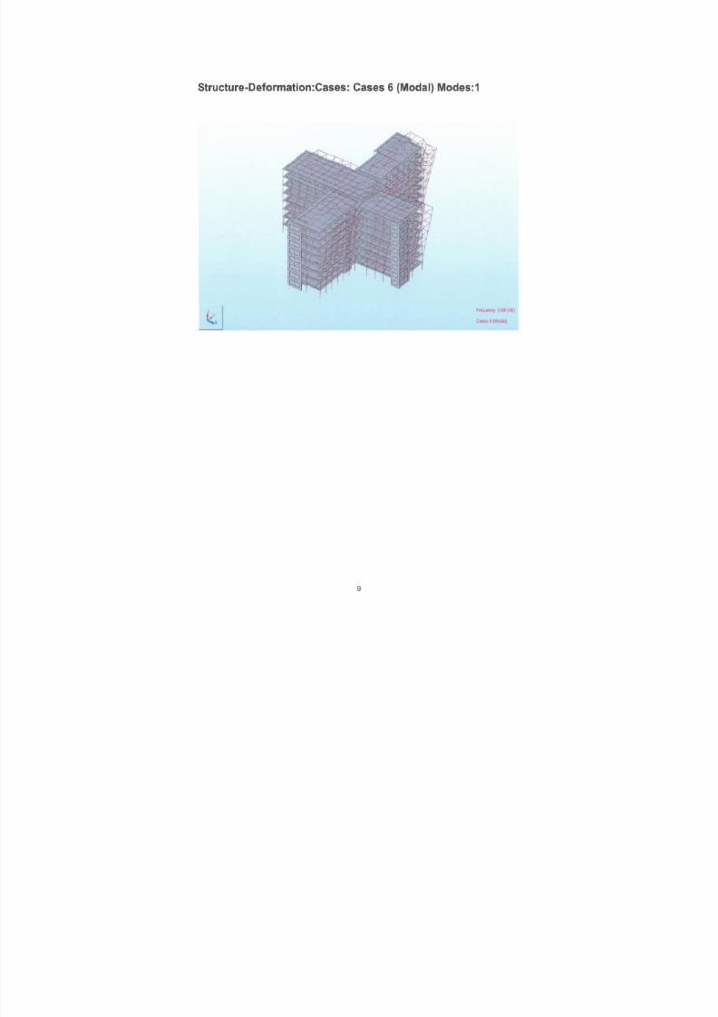
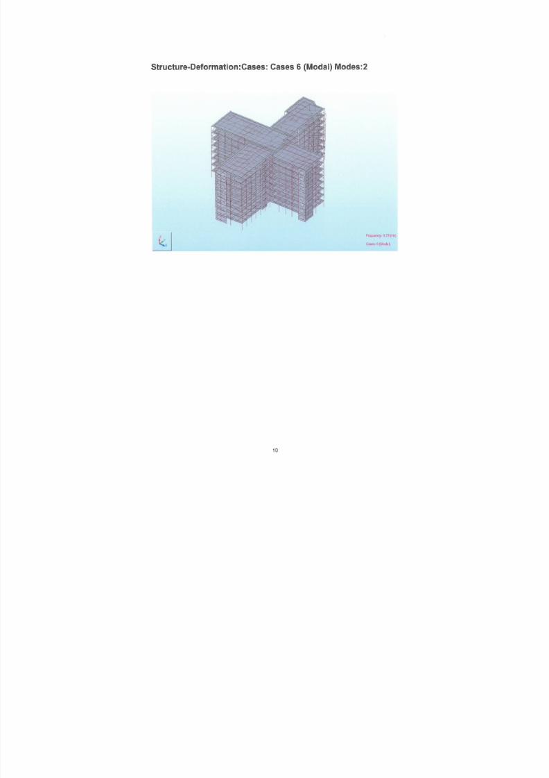
3.3 Response Spectrum Method
The methodology used for the structural response is a linear detknown as the Response Spectrum Method. The structural stiffnedamping are modelled in a finite element model. Then the free vcharacteristics of the system are determined and the response sperformed.
3.3.1 Analysis software
The analyses are carried out in the finite element method prograMillennium. For references see, http://www.robobat.com.
3.3.2 Modelling
All columns are modelled as continuous with fixed base and all scontinuous plates. All structural walls are modelled with thicknesstructural walls and cladding are not modelled.
All buildings are modelled fixed at the ground level. Number of sheights are given in Table 1
Table 1 Number of storeys and building height
.
Building Number of storeys Building heigths [m]
Bed ward 8 32
T 7 28

7/18/2019 Sketch - Seismic Report
http://slidepdf.com/reader/full/sketch-seismic-report 12/106
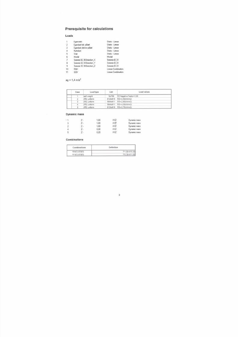
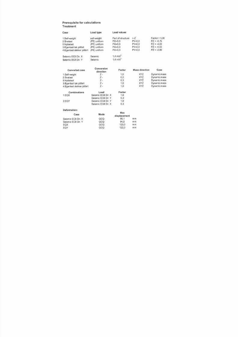
Gravity loads are evenly distributed on all floors. The values are
Table 2 Loads
Load type Value [kN/m2]
Dead load slabs1) 10.3Dead load roof 1) 8Dead load structural walls 7,5Live load 4.0Snow 0.75
1) All slabs are modelled with thickness t=300mm and remainingadded with additional load cases.
Load factors for seismic load cases are shown in Table 3
Table 3 Load factors
.
Load type Load factorDead load 1.0Live load 0.3Snow 0.2Earthquake 1.0
3.3.4 Materials and material factors
In the calculations Young’s modulus and the shear modulus for tstructural walls are reduced with 50% to account for reduced stifafter cracking. Originally and reduced values are shown in Table
Table 4 Material properties for structural walls
MaterialOriginal value [N/mm
2] Value used in calc
Concrete B30Young’s modulus 26000 N/mm2 13000
Shear modulus 11000 N/mm2 5500 N
Material factor for concrete strength is 1.0.

7/18/2019 Sketch - Seismic Report
http://slidepdf.com/reader/full/sketch-seismic-report 13/106
3.4 Seismic action
3.4.1 PGA
The seismic action is described by peak ground acceleration wit475 years, see Figure 4. The PGA chosen for the seismic design
Figure 5 Probabilistic determined PGA for Reykjavik with a return period of 475 year
3.4.2 Elastic response spectrum
The seismic action is described by the elastic response spectrumsuitable for earthquakes with magnitude < 5.5 on the Richter sca
7/18/2019 Sketch - Seismic Report
http://slidepdf.com/reader/full/sketch-seismic-report 14/106
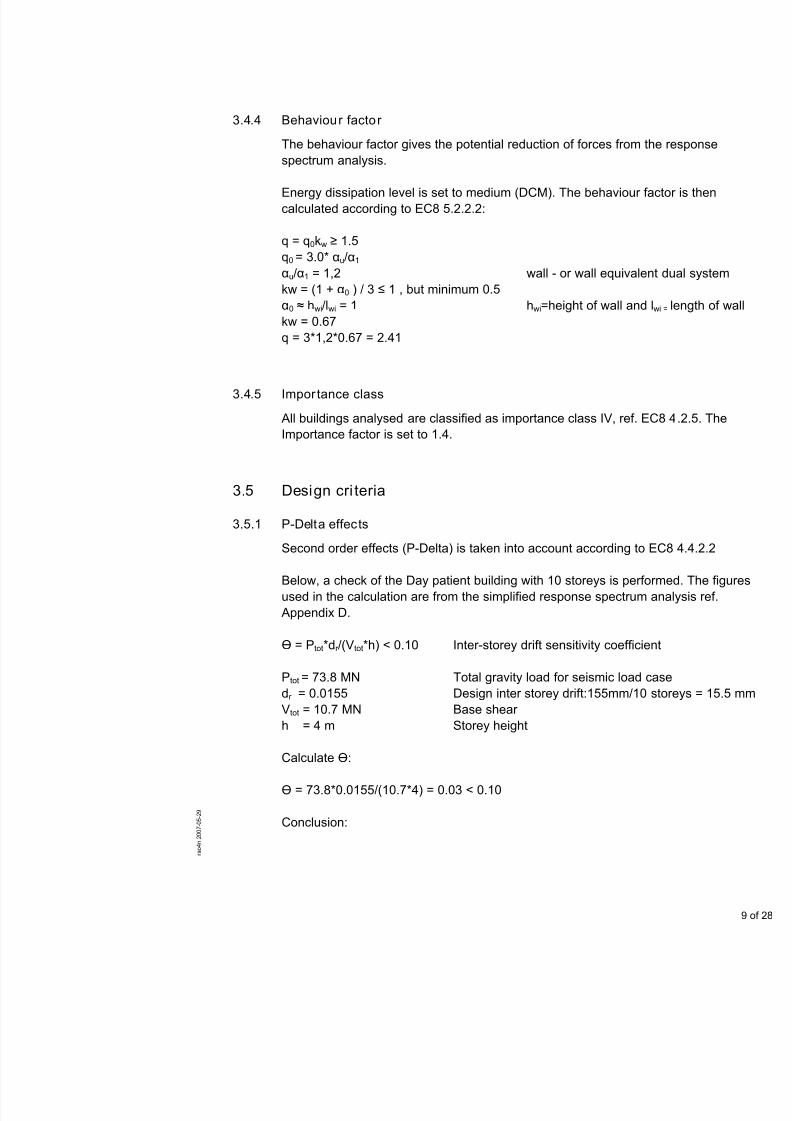
3.4.4 Behaviour factor
The behaviour factor gives the potential reduction of forces fromspectrum analysis.
Energy dissipation level is set to medium (DCM). The behaviourcalculated according to EC8 5.2.2.2:
q = q0kw ≥ 1.5q0 = 3.0* αu/α1 αu/α1 = 1,2 wall - or wall equivalkw = (1 + α0 ) / 3 ≤ 1 , but minimum 0.5α0 ≈ hwi/lwi = 1 hwi=height of wall ankw = 0.67q = 3*1,2*0.67 = 2.41
3.4.5 Importance class
All buildings analysed are classified as importance class IV, ref. Importance factor is set to 1.4.
3.5 Design cri teria
3.5.1 P-Delta effects
Second order effects (P-Delta) is taken into account according to
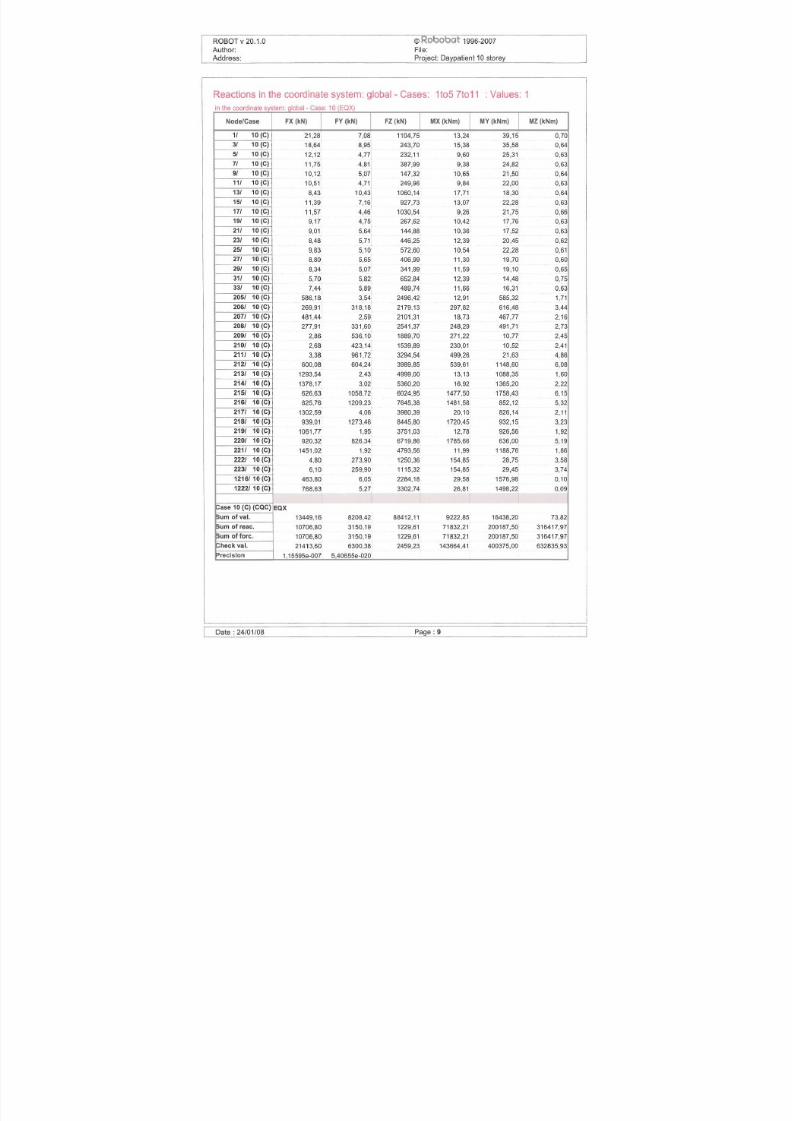
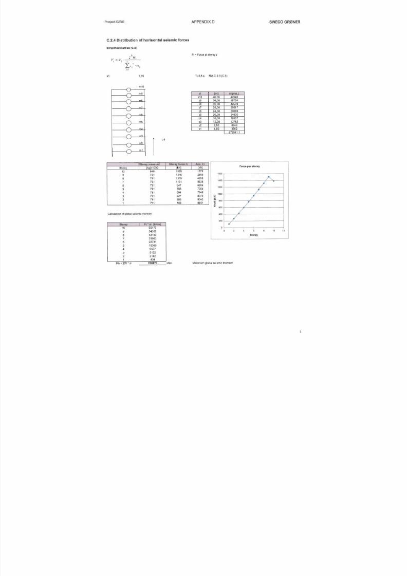
Below, a check of the Day patient building with 10 storeys is perused in the calculation are from the simplified response spectrum Appendix D.
Ө = Ptot*dr /(Vtot*h) < 0.10 Inter-storey drift sensitivity coeffic
Ptot = 73.8 MN Total gravity load for seismic load
7/18/2019 Sketch - Seismic Report
http://slidepdf.com/reader/full/sketch-seismic-report 15/106
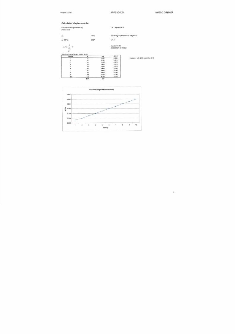
For the Day Patient building with a height of 40 m and maximummm, P-Delta effects can be neglected. Based on this result, P-D
neglected for all building types investigated in this report.
3.5.2 Limitation of inter-storey drift
Maximum allowable inter-storey drift is limited to 0.005*H were HEC8 4.4.3.2.
Example Outpatient 10 storey:
Maximum displacement in top of the structure is approximately 0
3.5.3 Limitation of axial loads
Buckling of the structural walls is associated with a non ductile fa
axial loads due to seismic forces is limited to maximum 40% of cstrength.
Axial normalised loads <0.4 ref EC8 5.4.3.4.1 (2)
4 Results
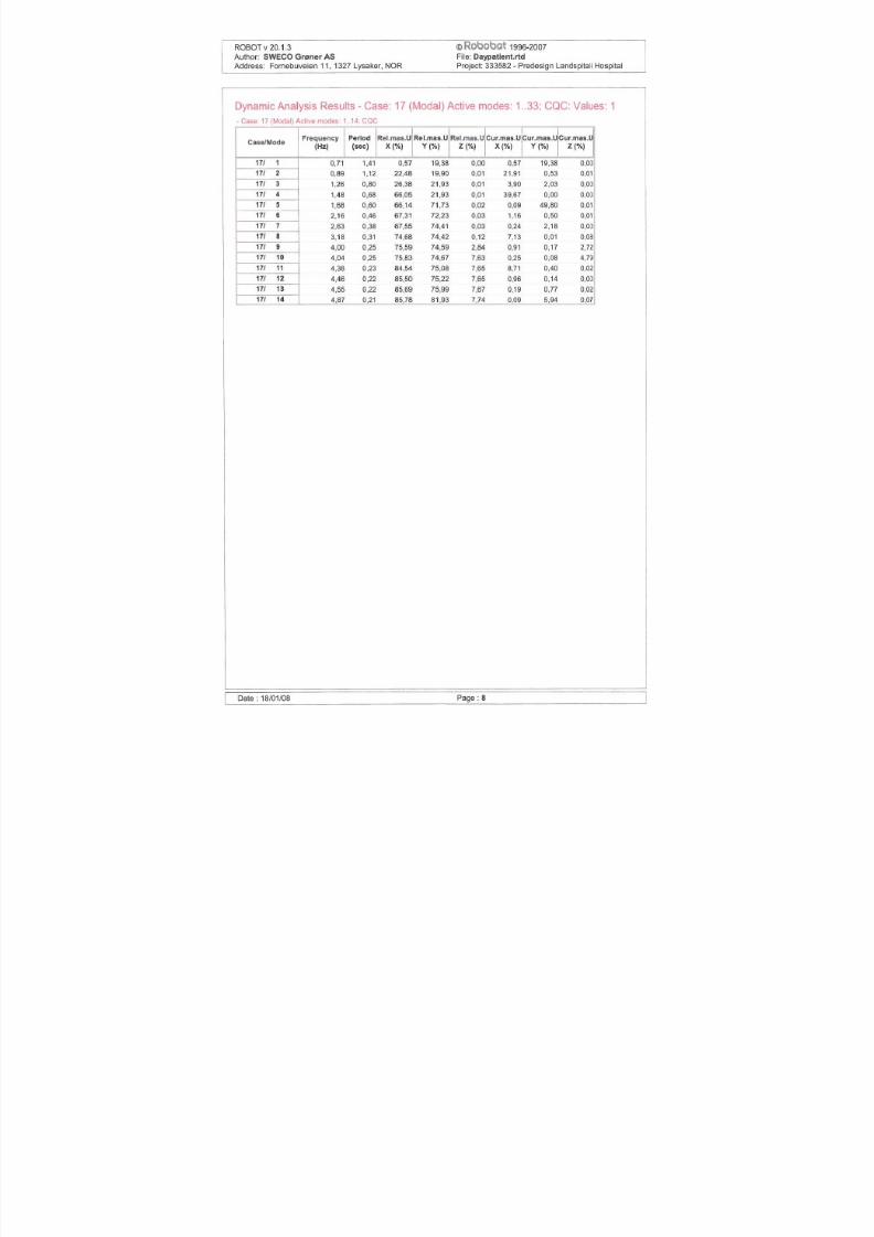
4.1 Introduction
Detailed results from the seismic analysis such as deformed geofrequencies and Eigen modes are presented in Appendix A, B a
The results most relevant for the conceptual design are shown insections.
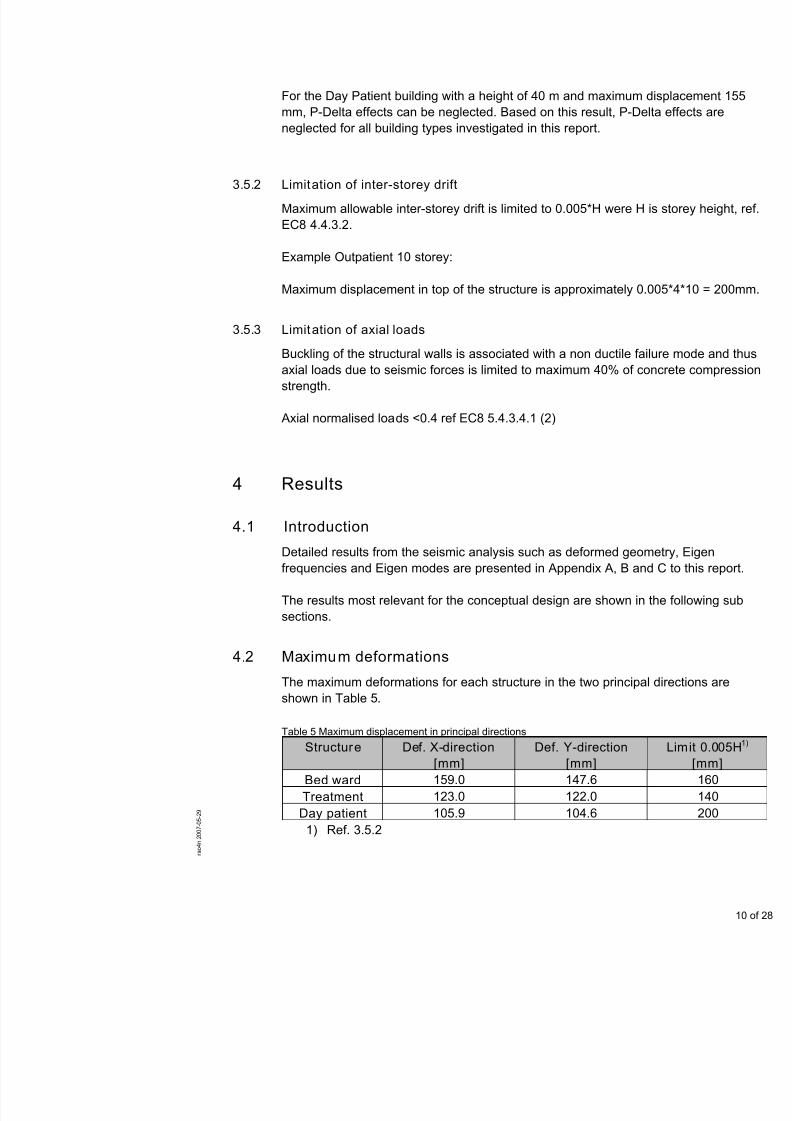
4.2 Maximum deformations
The maximum deformations for each structure in the two princip
7/18/2019 Sketch - Seismic Report
http://slidepdf.com/reader/full/sketch-seismic-report 16/106
All calculated deformations are within the limits given in EC8.
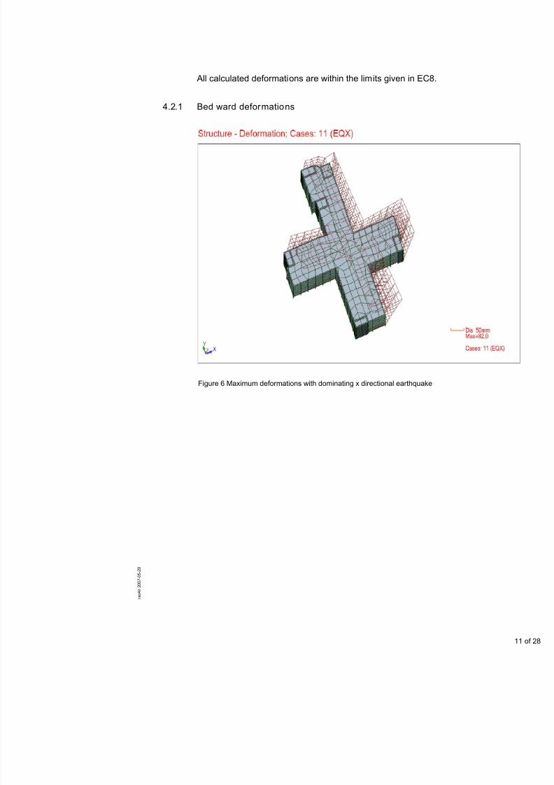
4.2.1 Bed ward deformations
Figure 6 Maximum deformations with dominating x directional earthquake
7/18/2019 Sketch - Seismic Report
http://slidepdf.com/reader/full/sketch-seismic-report 17/106
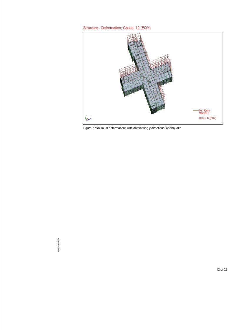
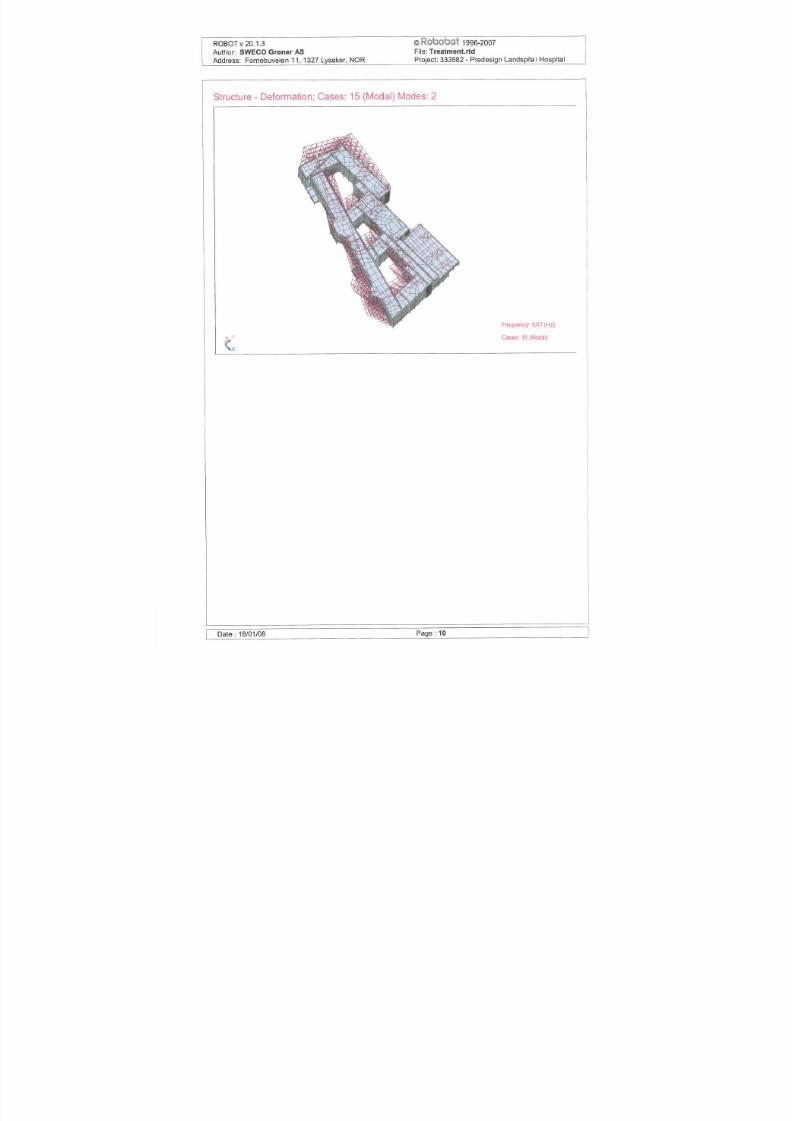
Figure 7 Maximum deformations with dominating y directional earthquake
7/18/2019 Sketch - Seismic Report
http://slidepdf.com/reader/full/sketch-seismic-report 18/106
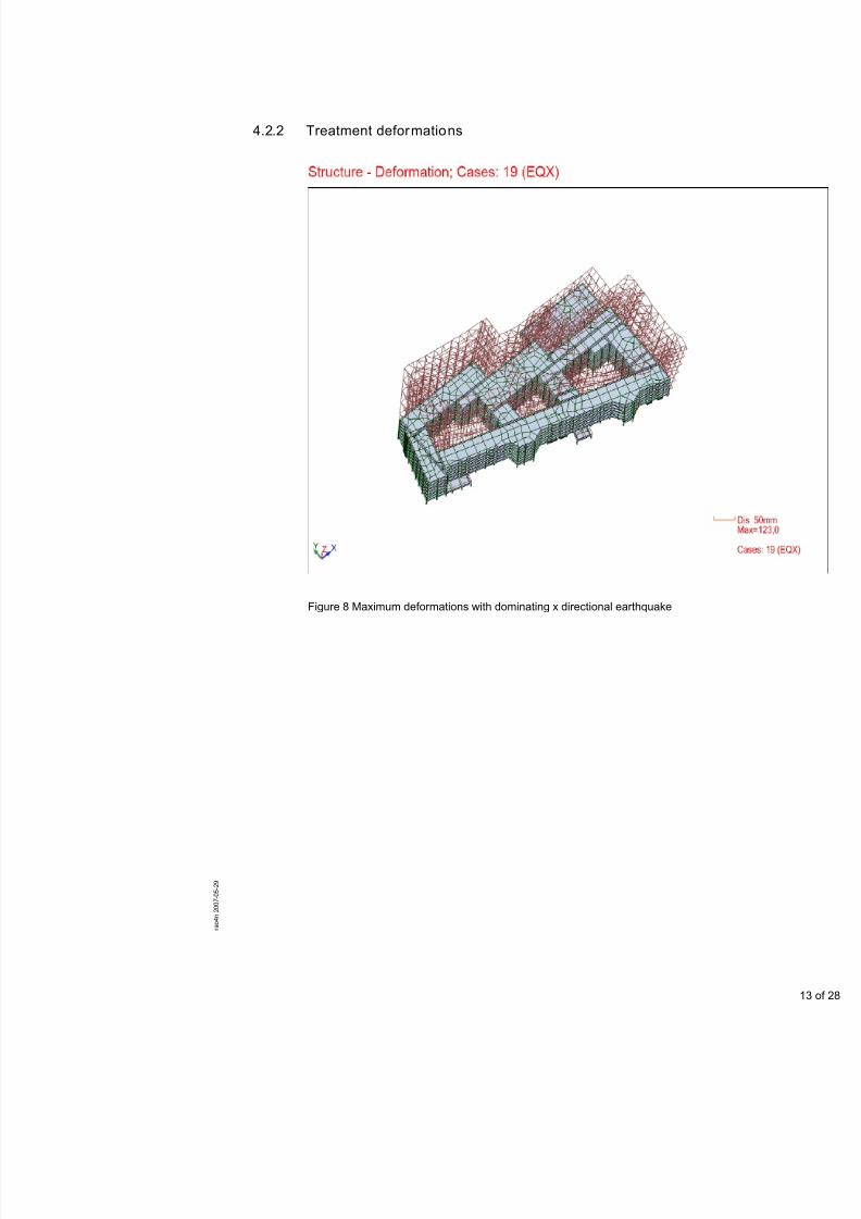
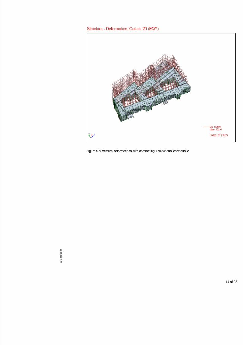
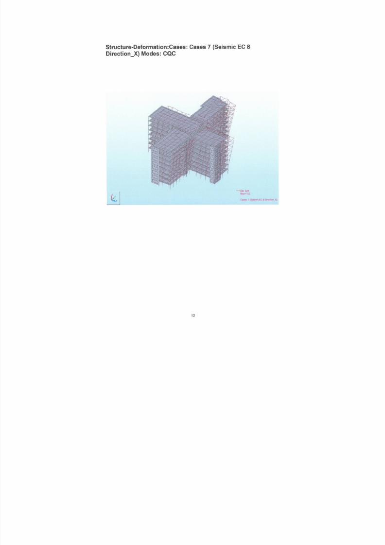
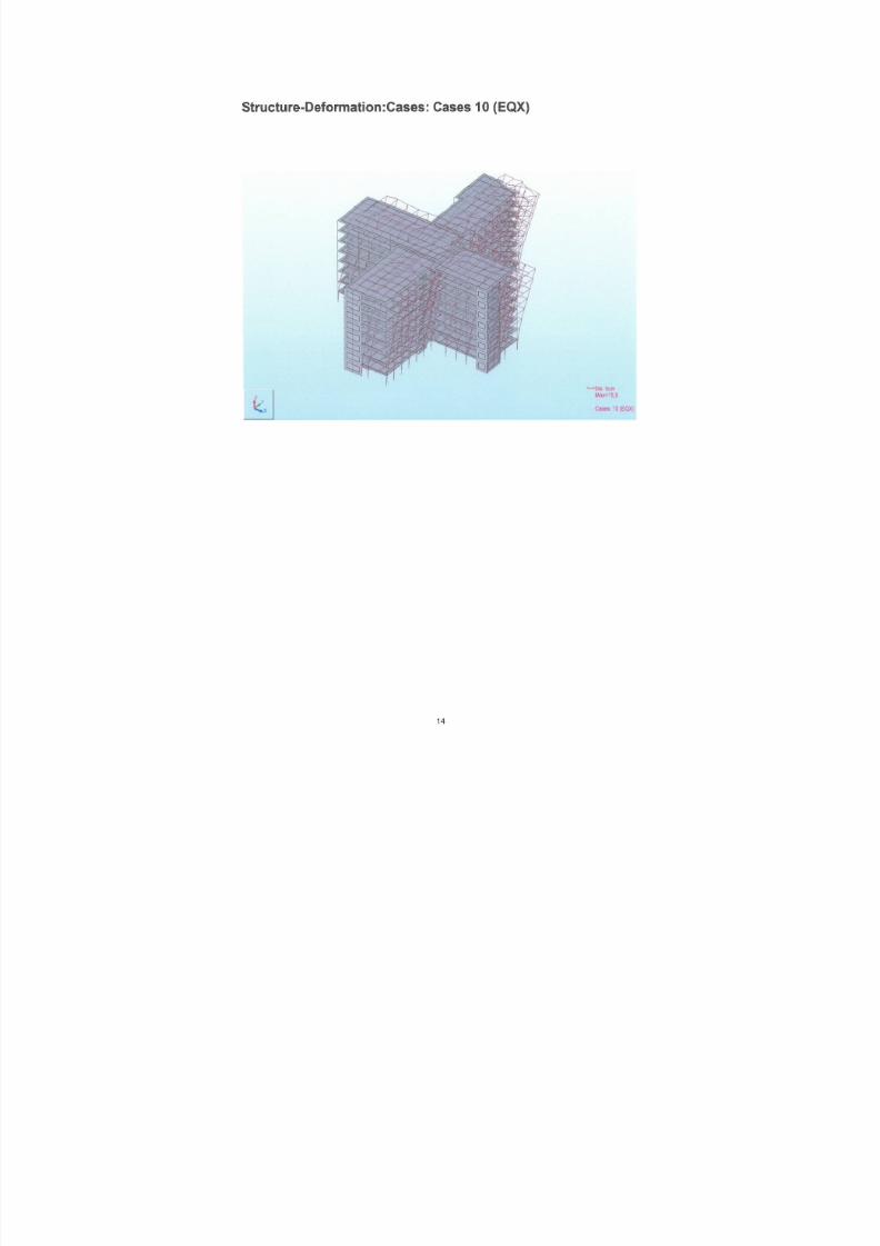
4.2.2 Treatment deformations
Figure 8 Maximum deformations with dominating x directional earthquake
7/18/2019 Sketch - Seismic Report
http://slidepdf.com/reader/full/sketch-seismic-report 19/106
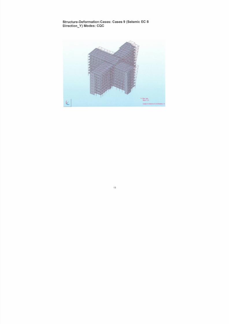
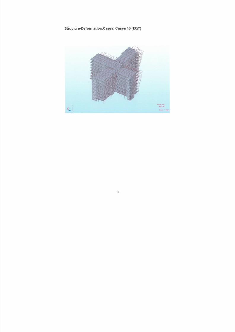
Figure 9 Maximum deformations with dominating y directional earthquake

7/18/2019 Sketch - Seismic Report
http://slidepdf.com/reader/full/sketch-seismic-report 20/106
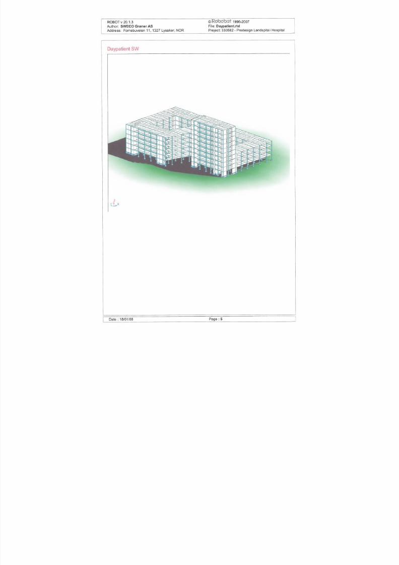
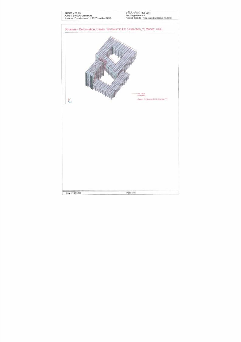
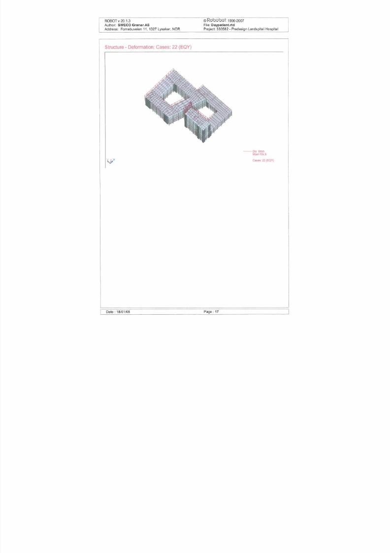
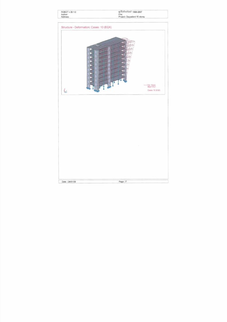
4.2.3 Day patient deformations
Figure 10 Maximum deformations with dominating x directional earthquake

7/18/2019 Sketch - Seismic Report
http://slidepdf.com/reader/full/sketch-seismic-report 21/106
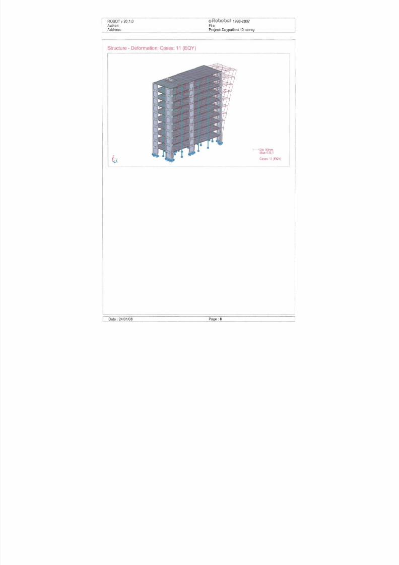
Figure 11 Maximum deformations with dominating y directional earthquake
4.3 Maximum axial stress
Maximum axial concrete stress due to seismic loading is shown Table 6
Table 6 Maximum normalized vertical load
and compared with maximum allowable concrete stress
Structure Concrete stress [Mpa] Limit [M
ConcreteHorizontal dir. Vertical dir.
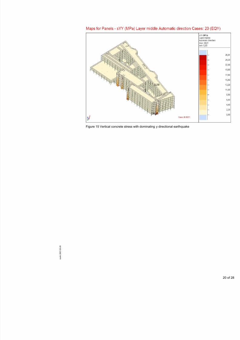
26.242) 8.89 9.52Bed ward
26 012)10 88 9 52Treatment
7/18/2019 Sketch - Seismic Report
http://slidepdf.com/reader/full/sketch-seismic-report 22/106
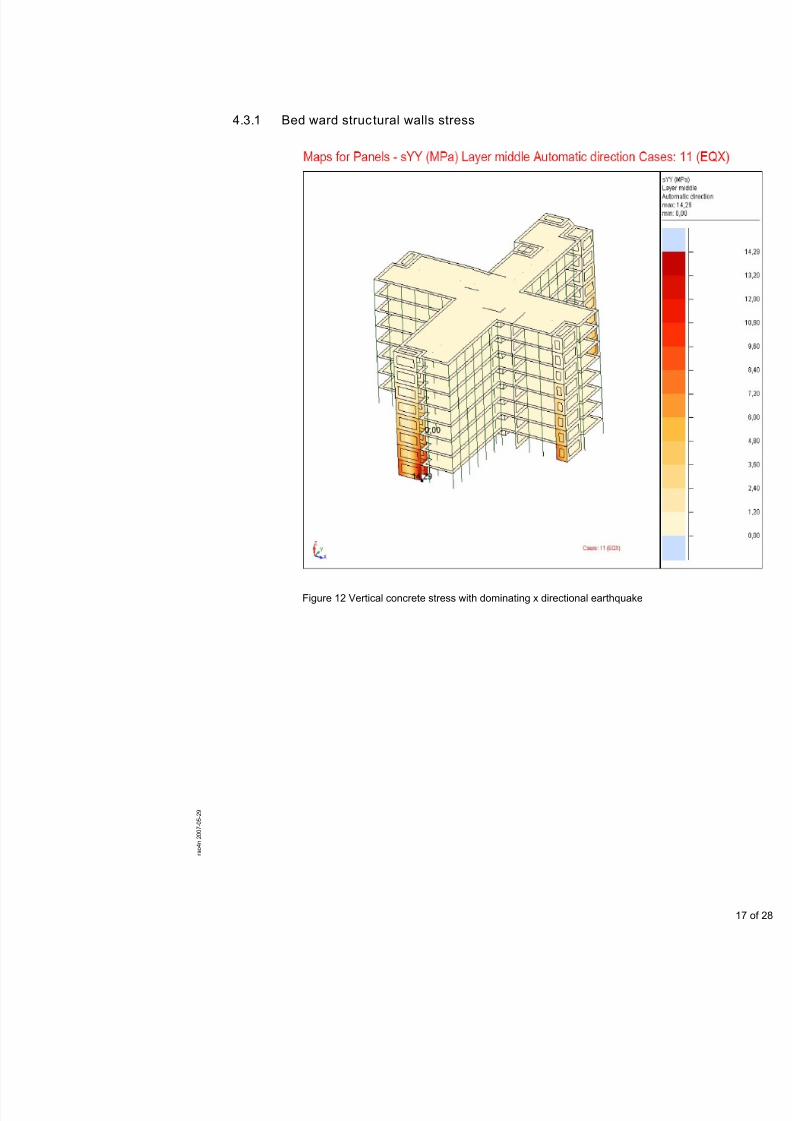
4.3.1 Bed ward structural walls stress
Figure 12 Vertical concrete stress with dominating x directional earthquake
7/18/2019 Sketch - Seismic Report
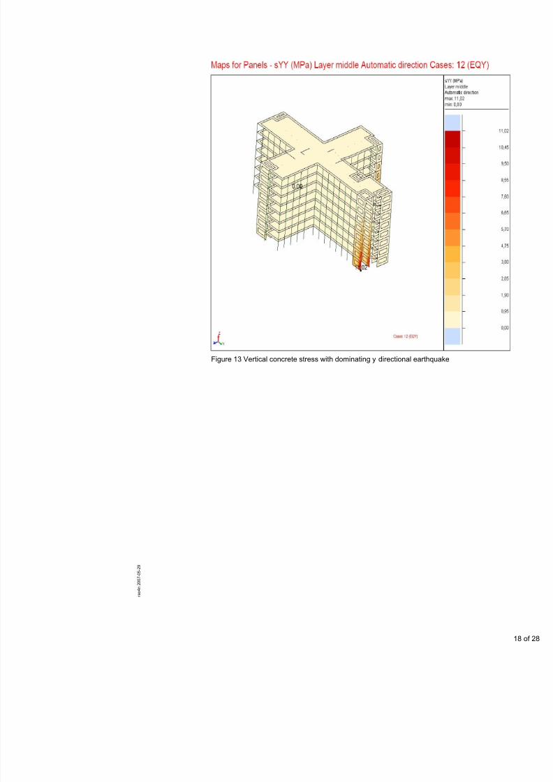
http://slidepdf.com/reader/full/sketch-seismic-report 23/106
Figure 13 Vertical concrete stress with dominating y directional earthquak
7/18/2019 Sketch - Seismic Report
http://slidepdf.com/reader/full/sketch-seismic-report 24/106
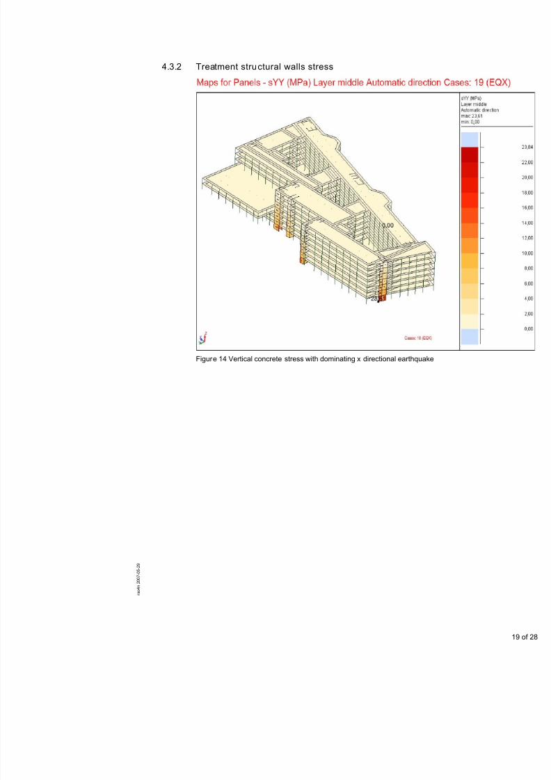
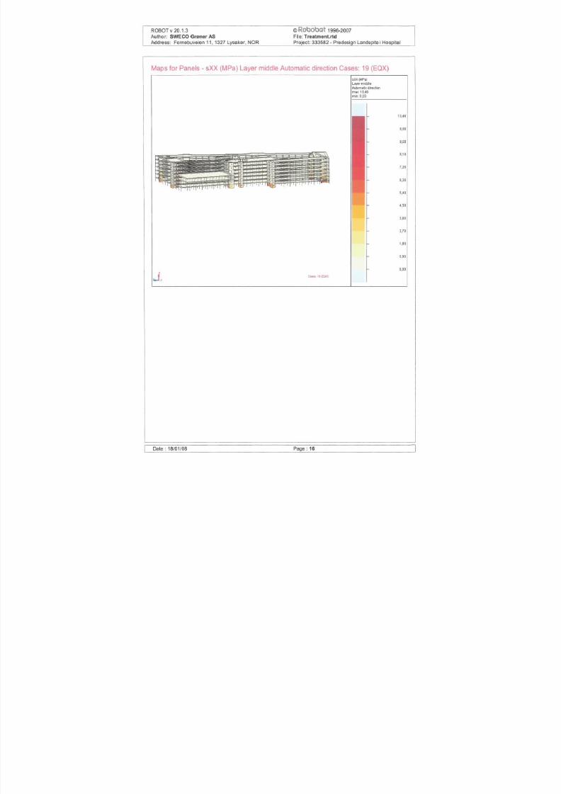
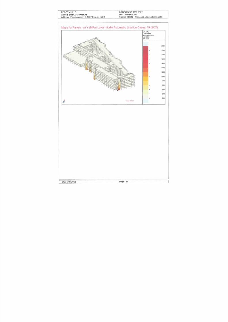
4.3.2 Treatment structural walls stress
Figur e 14 Vertical concrete stress with dominating x directional earthquake
7/18/2019 Sketch - Seismic Report
http://slidepdf.com/reader/full/sketch-seismic-report 25/106
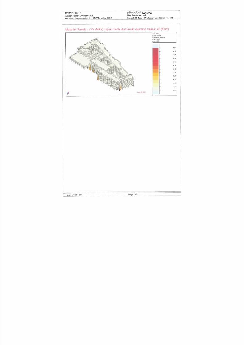
Figure 15 Vertical concrete stress with dominating y directional earthquake

7/18/2019 Sketch - Seismic Report
http://slidepdf.com/reader/full/sketch-seismic-report 26/106
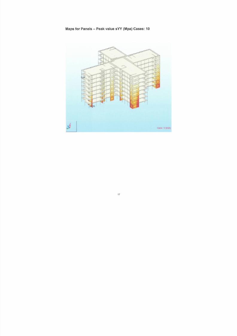
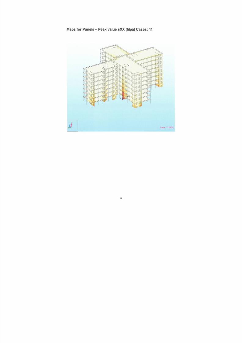
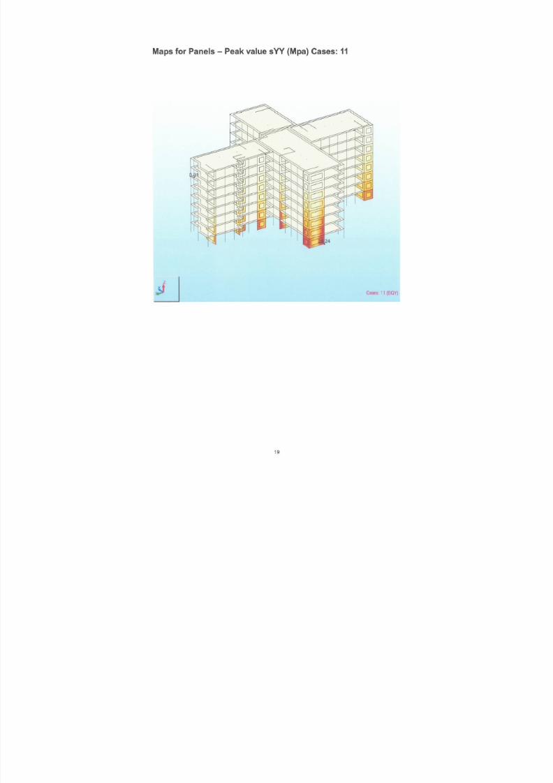
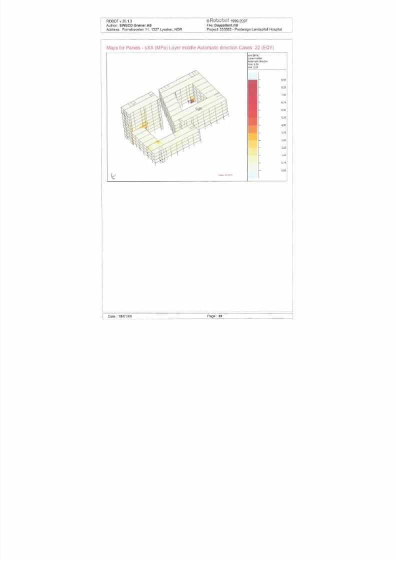
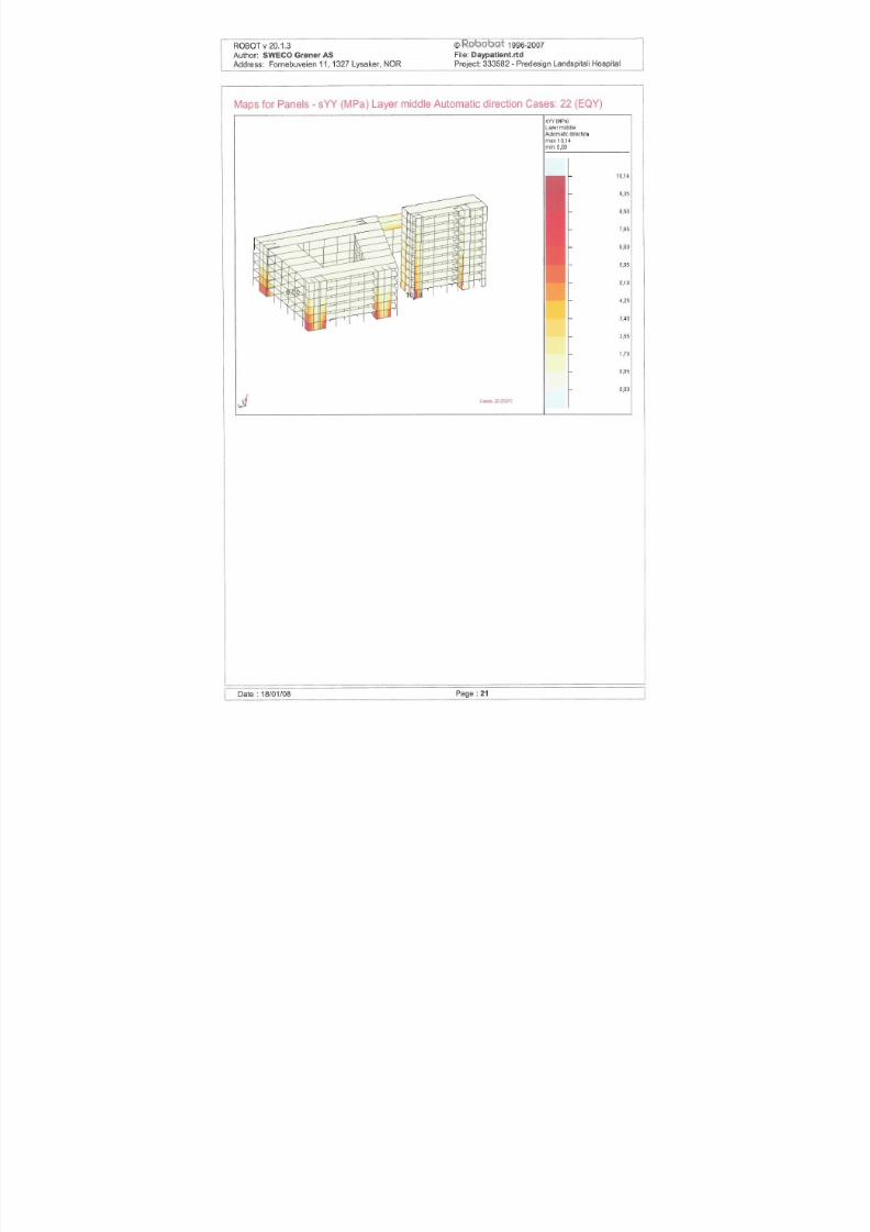
4.3.3 Day patient structural walls stress
Figure 16 Vertical concrete stress with dominating x directional earthquake

7/18/2019 Sketch - Seismic Report
http://slidepdf.com/reader/full/sketch-seismic-report 27/106
Figure 17 Vertical concrete stress with dominating y directional earthquake
5 Verification by hand calculations
5 1 Introduction
7/18/2019 Sketch - Seismic Report
http://slidepdf.com/reader/full/sketch-seismic-report 28/106
Details from the simplified analysis is given in Appendix D.
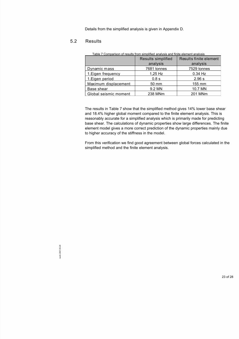
5.2 Results
Table 7 Comparison of results from simplified analysis and finite element
Results simplified
analysis
Results
a
Dynamic mass 7681 tonnes 75
1.Eigen frequency 1,25 Hz 1.Eigen period 0.8 s Maximum displacement 50 mm Base shear 9.2 MN 1Global seismic moment 238 MNm 2
The results in Table 7 show that the simplified method gives 14%and 18.4% higher global moment compared to the finite elementreasonably accurate for a simplified analysis which is primarily mbase shear. The calculations of dynamic properties show large delement model gives a more correct prediction of the dynamic prto higher accuracy of the stiffness in the model.
From this verification we find good agreement between global fo
simplified method and the finite element analysis.

7/18/2019 Sketch - Seismic Report
http://slidepdf.com/reader/full/sketch-seismic-report 29/106
6 References
/1/ Eurocode 8, EN1998-1-December 2004 /2/ Norwegian code NS3491-12 Design actions Part 12: Seismic actions

7/18/2019 Sketch - Seismic Report
http://slidepdf.com/reader/full/sketch-seismic-report 30/106

7/18/2019 Sketch - Seismic Report
http://slidepdf.com/reader/full/sketch-seismic-report 31/106

7/18/2019 Sketch - Seismic Report
http://slidepdf.com/reader/full/sketch-seismic-report 32/106
7/18/2019 Sketch - Seismic Report
http://slidepdf.com/reader/full/sketch-seismic-report 33/106

7/18/2019 Sketch - Seismic Report
http://slidepdf.com/reader/full/sketch-seismic-report 34/106
7/18/2019 Sketch - Seismic Report
http://slidepdf.com/reader/full/sketch-seismic-report 35/106
7/18/2019 Sketch - Seismic Report
http://slidepdf.com/reader/full/sketch-seismic-report 36/106
7/18/2019 Sketch - Seismic Report
http://slidepdf.com/reader/full/sketch-seismic-report 37/106

7/18/2019 Sketch - Seismic Report
http://slidepdf.com/reader/full/sketch-seismic-report 38/106
7/18/2019 Sketch - Seismic Report
http://slidepdf.com/reader/full/sketch-seismic-report 39/106
7/18/2019 Sketch - Seismic Report
http://slidepdf.com/reader/full/sketch-seismic-report 40/106

7/18/2019 Sketch - Seismic Report
http://slidepdf.com/reader/full/sketch-seismic-report 41/106
7/18/2019 Sketch - Seismic Report
http://slidepdf.com/reader/full/sketch-seismic-report 42/106
7/18/2019 Sketch - Seismic Report
http://slidepdf.com/reader/full/sketch-seismic-report 43/106
7/18/2019 Sketch - Seismic Report
http://slidepdf.com/reader/full/sketch-seismic-report 44/106
7/18/2019 Sketch - Seismic Report
http://slidepdf.com/reader/full/sketch-seismic-report 45/106

7/18/2019 Sketch - Seismic Report
http://slidepdf.com/reader/full/sketch-seismic-report 46/106
7/18/2019 Sketch - Seismic Report
http://slidepdf.com/reader/full/sketch-seismic-report 47/106
7/18/2019 Sketch - Seismic Report
http://slidepdf.com/reader/full/sketch-seismic-report 48/106
7/18/2019 Sketch - Seismic Report
http://slidepdf.com/reader/full/sketch-seismic-report 49/106

7/18/2019 Sketch - Seismic Report
http://slidepdf.com/reader/full/sketch-seismic-report 50/106

7/18/2019 Sketch - Seismic Report
http://slidepdf.com/reader/full/sketch-seismic-report 51/106

7/18/2019 Sketch - Seismic Report
http://slidepdf.com/reader/full/sketch-seismic-report 52/106
7/18/2019 Sketch - Seismic Report
http://slidepdf.com/reader/full/sketch-seismic-report 53/106

7/18/2019 Sketch - Seismic Report
http://slidepdf.com/reader/full/sketch-seismic-report 54/106

7/18/2019 Sketch - Seismic Report
http://slidepdf.com/reader/full/sketch-seismic-report 55/106
7/18/2019 Sketch - Seismic Report
http://slidepdf.com/reader/full/sketch-seismic-report 56/106

7/18/2019 Sketch - Seismic Report
http://slidepdf.com/reader/full/sketch-seismic-report 57/106

7/18/2019 Sketch - Seismic Report
http://slidepdf.com/reader/full/sketch-seismic-report 58/106

7/18/2019 Sketch - Seismic Report
http://slidepdf.com/reader/full/sketch-seismic-report 59/106
7/18/2019 Sketch - Seismic Report
http://slidepdf.com/reader/full/sketch-seismic-report 60/106

7/18/2019 Sketch - Seismic Report
http://slidepdf.com/reader/full/sketch-seismic-report 61/106

7/18/2019 Sketch - Seismic Report
http://slidepdf.com/reader/full/sketch-seismic-report 62/106

7/18/2019 Sketch - Seismic Report
http://slidepdf.com/reader/full/sketch-seismic-report 63/106

7/18/2019 Sketch - Seismic Report
http://slidepdf.com/reader/full/sketch-seismic-report 64/106

7/18/2019 Sketch - Seismic Report
http://slidepdf.com/reader/full/sketch-seismic-report 65/106
7/18/2019 Sketch - Seismic Report
http://slidepdf.com/reader/full/sketch-seismic-report 66/106
7/18/2019 Sketch - Seismic Report
http://slidepdf.com/reader/full/sketch-seismic-report 67/106

7/18/2019 Sketch - Seismic Report
http://slidepdf.com/reader/full/sketch-seismic-report 68/106
7/18/2019 Sketch - Seismic Report
http://slidepdf.com/reader/full/sketch-seismic-report 69/106

7/18/2019 Sketch - Seismic Report
http://slidepdf.com/reader/full/sketch-seismic-report 70/106

7/18/2019 Sketch - Seismic Report
http://slidepdf.com/reader/full/sketch-seismic-report 71/106

7/18/2019 Sketch - Seismic Report
http://slidepdf.com/reader/full/sketch-seismic-report 72/106

7/18/2019 Sketch - Seismic Report
http://slidepdf.com/reader/full/sketch-seismic-report 73/106

7/18/2019 Sketch - Seismic Report
http://slidepdf.com/reader/full/sketch-seismic-report 74/106
7/18/2019 Sketch - Seismic Report
http://slidepdf.com/reader/full/sketch-seismic-report 75/106

7/18/2019 Sketch - Seismic Report
http://slidepdf.com/reader/full/sketch-seismic-report 76/106
7/18/2019 Sketch - Seismic Report
http://slidepdf.com/reader/full/sketch-seismic-report 77/106
7/18/2019 Sketch - Seismic Report
http://slidepdf.com/reader/full/sketch-seismic-report 78/106
7/18/2019 Sketch - Seismic Report
http://slidepdf.com/reader/full/sketch-seismic-report 79/106
7/18/2019 Sketch - Seismic Report
http://slidepdf.com/reader/full/sketch-seismic-report 80/106
7/18/2019 Sketch - Seismic Report
http://slidepdf.com/reader/full/sketch-seismic-report 81/106
7/18/2019 Sketch - Seismic Report
http://slidepdf.com/reader/full/sketch-seismic-report 82/106

7/18/2019 Sketch - Seismic Report
http://slidepdf.com/reader/full/sketch-seismic-report 83/106

7/18/2019 Sketch - Seismic Report
http://slidepdf.com/reader/full/sketch-seismic-report 84/106
7/18/2019 Sketch - Seismic Report
http://slidepdf.com/reader/full/sketch-seismic-report 85/106

7/18/2019 Sketch - Seismic Report
http://slidepdf.com/reader/full/sketch-seismic-report 86/106
7/18/2019 Sketch - Seismic Report
http://slidepdf.com/reader/full/sketch-seismic-report 87/106

7/18/2019 Sketch - Seismic Report
http://slidepdf.com/reader/full/sketch-seismic-report 88/106

7/18/2019 Sketch - Seismic Report
http://slidepdf.com/reader/full/sketch-seismic-report 89/106
7/18/2019 Sketch - Seismic Report
http://slidepdf.com/reader/full/sketch-seismic-report 90/106
7/18/2019 Sketch - Seismic Report
http://slidepdf.com/reader/full/sketch-seismic-report 91/106

7/18/2019 Sketch - Seismic Report
http://slidepdf.com/reader/full/sketch-seismic-report 92/106

7/18/2019 Sketch - Seismic Report
http://slidepdf.com/reader/full/sketch-seismic-report 93/106
7/18/2019 Sketch - Seismic Report
http://slidepdf.com/reader/full/sketch-seismic-report 94/106

7/18/2019 Sketch - Seismic Report
http://slidepdf.com/reader/full/sketch-seismic-report 95/106

7/18/2019 Sketch - Seismic Report
http://slidepdf.com/reader/full/sketch-seismic-report 96/106

7/18/2019 Sketch - Seismic Report
http://slidepdf.com/reader/full/sketch-seismic-report 97/106
7/18/2019 Sketch - Seismic Report
http://slidepdf.com/reader/full/sketch-seismic-report 98/106
7/18/2019 Sketch - Seismic Report
http://slidepdf.com/reader/full/sketch-seismic-report 99/106
7/18/2019 Sketch - Seismic Report
http://slidepdf.com/reader/full/sketch-seismic-report 100/106
7/18/2019 Sketch - Seismic Report
http://slidepdf.com/reader/full/sketch-seismic-report 101/106

7/18/2019 Sketch - Seismic Report
http://slidepdf.com/reader/full/sketch-seismic-report 102/106

7/18/2019 Sketch - Seismic Report
http://slidepdf.com/reader/full/sketch-seismic-report 103/106

7/18/2019 Sketch - Seismic Report
http://slidepdf.com/reader/full/sketch-seismic-report 104/106
7/18/2019 Sketch - Seismic Report
http://slidepdf.com/reader/full/sketch-seismic-report 105/106
7/18/2019 Sketch - Seismic Report
http://slidepdf.com/reader/full/sketch-seismic-report 106/106