sm1120 j-50-b jogger 111914 - syntronmh.comsyntronmh.com/documents/pdf/sm1120_j-50-b...
TRANSCRIPT
Service Instructions Syntron® Jogger Model: J-50-B

1
Syntron® J-50-B Jogger ♦♦♦♦♦♦♦♦♦♦♦♦♦♦♦♦♦♦♦♦♦♦♦♦♦♦♦♦♦♦♦♦♦♦♦♦♦♦♦♦♦♦♦♦♦♦♦♦♦♦♦♦♦♦♦♦♦♦♦♦♦♦♦♦ INSTALLATION ♦♦♦♦♦♦♦♦♦♦♦♦♦♦♦♦♦♦♦♦ OPERATION ♦♦♦♦♦♦♦♦♦♦♦♦♦♦♦♦♦♦♦♦♦♦♦♦ MAINTENANCE Thank you for buying your equipment from Syntron Material Handling, LLC. This manual will help you to understand how your equipment operates and what is required to maintain peak performance. Please read it thoroughly and keep it on file for reference. Your satisfaction is important to us, so pease direct any comments to our Marketing Communications Department. TABLE OF CONTENTS Introduction .......................................1 Inspection .........................................1 Safety Instructions ............................2 Installation ........................................2 Operation ..........................................2 Disassembling the Jogger .................2 Replacing the Rubber Mounts ...........3 Replacing the Magnet Assy ..............3 Reassembling the Jogger .................4 Adjusting the Air Gap ........................4 Maintenance .....................................5 Troubleshooting ................................6 Specifications J-50 w/Flat Deck ...........................7 J-50 w/Single Tray Tilt Rack .........7 J-50 w4 or 6 Pocket Tilt Rack .......8 J-50 w/Tilt Rack ............................8 Parts Illustration Diagram ..................9 Parts List...........................................10 INTRODUCTION The Sytron® Electromagnetic J-50-B Jogger I used to jog and pack paper stock. The vibrating action produced by the magnet assembly is transmitted to the deck through rubber mounts. The control assembly consists of an OFF/ON switch, a rheostat to control the amplitude of the vibration, a rectifier to convert AC to DC, and a fuse. INSPECTION Upon receipt, carefully unpack the jogger and inspect it for any damage that may have occurred during shipment. If damage is found, contact the shipping carrier and Syntron Material Handling, LLC. immediately.

2
SAFETY INSTRUCTIONS
CAUTION: Product safety labels must be highly visible on the equipment. Etstablish a regular schedule to check visibility. If the safety labels need replaced, contact Syntron Material Handling, LLC. for an additional supply free of charge.
WARNING: Do not use the J-50 Jogger for anything other than jogging and aligning paper stock. Contact SMH Corporation before making any additions to the jogger. Unauthorized
additions and/or modifications to the jogger may present a safety hazard to the operator and void the warranty. INSTALLATION Place the jogger in its operation location and plug it into a self-grounding electrical receptacle. The power supply voltage and freqency requirements are designated on the nameplate.
WARNING: The jogger weighs over 90 pounds (40.8 kg.); lift it by the base only.
CAUTION: Before moving or handling the jogger, unplug the cord and wrap it around the holders on the back of the jogger.
OPERATION To start the jogger, turn the switch to the ON position. To stop the jogger, turn the switch to the OFF position. To increase amplitude, turn the control knob on the front panel clockwise. To decrease amplitude, turn the control knob counterclockwise. DISASSEMBLING THE JOGGER The letters in parentheses correspond to the parts list and illustration on pages 9, 10, and 11.
WARNING: Unplug the electrical cord before disassembling the jogger. Coil and secure the cord to the jogger before moving it.
If the jogger is equipped with a flat deck, it is not necessary to remove the deck. If it is equipped with a tilted deck, it is necessary to remove the deck and deck adaptor (B). Place the jogger drive assembly in an upside-down position. If the jogger is equipped with a tilted deck, supports are required to keep the jogger balanced while it is upside-down. Refer to Figure 1. Remove the six hex nuts and lockwashers (Y). Remove two rubber feet (AA) from opposite corners and replace them with 1/4-20 eyebolts. Use an appropriate lifting device and the eyebolts to lift the base assembly from the unit.

3
Do not damage the ground strap assembly (T). For ease of handling, disconnect the ground strap from the base (DD). REPLACING THE RUBBER MOUNTS NOTE: SMH recommends replacing all six rubber mounts rather than only a portion of them.
1. Disassemble the jogger according to the procedure outlined above. Remove the spacers(P, Q) from the six studs (R, S).
2. Remove the six rubber mounts (K, M) and the studs (j) from the cover (A).
3. Insert the studs (J) into the new mounts (K, M) and install the mounts into the top cover (A).
Use a high-strength sealant (N).
4. Insert the studs (R, S) and spacers (P,Q) into the mounts (K, M). Use a high strength sealant (N).
5. After the spacers (P, Q), studs (R, S), and new mounts (K, M) are correctly postioned and
installed, reassemble the jogger. NOTE: On 60-Hz units, place four mounts (K) at the corners and two mounts (M) in the center. On 50-Hz units, place four mounts (M) at the corners and two mounts (K) in the center. Spacer (Q) and stud (S) should be used with mount (M). Spacer (Q) and stud (S) should be used with mount (M). Spacer (P) and stud ( R ) should be used with mount (K). REPLACING THE MAGNET ASSEMBLY
1. Disassemble the jogger according to the disassembly procedure described on page 2. 2. With the base in an upright position, disconnect the magnet leads at the terminal block.
3. Lift the base and remove the two hex nuts and lockwashers (Z) which secure the magnet
assembly (FF) to the base (DD).
4. Install the new magnet assembly, arranging the spring washers (U) as shown in Figure 2.
5. Secure the magnet assembly (FF) to the base
(DD) with the hex nuts and lockwashers (Z).
6. Connect the magnet leads to the terminal block at the control panel (EE).
7. Reassemble the jogger.

4
REASSEMBLING THE JOGGER
1. Place the cover (A) (or cover and deck in the case of joggers with flat decks) upside down. Refer to Figure 1. Ensure that the spacers (Q, P) are arranged on the studs (R, S) as explained in the directions for replacing rubber mounts on page 2.
2. Use thr eyebolts and lifting device to suspend the base (DD) and magnet assembly (FF) over the
cover (A). 3. Align the studs (R,S) and connect the lower base assembly to the spacers (P, Q). 4. Replace the six hex nuts and lockwashers (Y) on the six studs (R, S).
5. Remove the eyebolts and replace each of with a rubber foot (AA).
6. With the jogger in an upright position, replace the deck adaptor (B) and deck (if it was
removed), using the lockwasher and cap screw (C). NOTE: After reassembling the jogger, the air gap must be adjusted. Refer to the instructions on page 4. ADJUSTING THE AIR GAP The air gap is the space that exists between the armature (G) and the magnet assembly (FF). Proper adjustment of theair gap is critical to good jogger performance.
CAUTION: If the unit makes aloud striking noise while operating, immediately shut off the power.
If the air gap is adjusted so that the armature and magnet are too close. The faces of these items will contact each other during jogger operation. This is called striking. A striking condition may cause severe mechanical damage.
CAUTION: Never open the air gap more than necessary. An excessive air gap draws more
current and reduces the power of the electromagnet, resulting in poor performace. If the air gap is adjusted so that armature and magnet are too far apart, the current draw will be excessive. A high-current condition may result in coil burn-out, failure of control components, or reduced performance.

5

6
To adjust the air gap, perform the following steps;
1. Turn off power to the unit. 2. Elevate the jogger in order to access the adjusting nuts (Z) on the bottom of the jogger. (See
Figure 3.)
3. Loosen the two adjusting nuts (z) so that they are both flush with base plate, with no tension on them.
4. Tighten each nut one full turn.
5. Turn on unit with control on 0%.
6. Begin turning up the control until the unit strikes. When the unit strikes, tighten each nut
(equally) about a quarter turn. Continue turning up the control and tightening the nuts until the control is set on 100% without striking.
Use an AC ammeter to check the current draw of the unit. Turning the hex nuts (Z) in a clockwise direction will increase the current and turning them in a counterclockwise direction will decrease the current. The current rating must not exceed 4 amps for a 115V unit or 2 amps for a 230V unit. When using an analog tong meter to read the current of the unit, the meter reading must alawys be multiplied by a value of 1.7. Due to the waveform characteristics of the jogger when operating, the meter does not reveal the same current as that designated on the nameplate. Therefore, the 1.7 multiplier must be used. When using a true RMS meter, the current is as indicated. All current readings must be taken at the control. MAINTENANCE
WARNING: Unplug the electrical cord before performing any maintenance on the jogger. Coil and secure the cord to the jogger before moving it. The J-50 Jogger requires minimal maintenance. It must be kept clean, and the external hardware must be kept tight.

7
TROUBLESHOOTING
PROBLEM CAUSE CORRECTION
Unit does not Operate
Blown fuse
Defective rheostat
Shorted wiring, loose connection, no
power to the unit
Replace*
Replace*
Repair
Drive assembly operates;
Jogger will not vibrate
Defective rectifier
Defective rubber mounts
Unit in contact with rigid object
Or adjacent surface
Replace*
Replace*
Isolate unit
Excessive noise
Armature and magnet Assemblies making contact
Adjust air gap
* Replace only with parts supplied or recommended by Syntron Material Handling.

8
SPECIFICATIONS J-50 with Flat Deck The J-50 with flat deck, featuring a hardwood maple deck, will jog paper stocks in sizes up to 17 x 22 inches and loads weighing up to 50 pounds. Stocks must be operator-held during jogging. InputWatts (115, 60 Hz) 40.0
Input Amps (115V, 60 Hz) 4.0 Input Amps (240v, 50 Hz) 2.4 Net Weight 90lb (41 kg)
14 x 20 Deck A B C D E F G
Inches 9-5/8 13-5/8 11-5/8 15-5/8 14 20 7-1/2 mm 244 346 295 397 356 508 190
17 x 22 Deck A B C D E F G
Inches 9-5/8 13-5/8 11-5/8 15-5/8 17 22 7-3/8 mm 244 346 295 397 432 559 187
J-50 with Single Tray Tilt Rack The J-50 with single tray tilt rack, featuring a tray rack with rubber strips for reduced noise, is designed to align checks and/or mail within a plastic or cardboard transit tray.
Input Watts (115, 60 Hz) 40.0 Input Amps (115V, 60 Hz) 4.0 Input Amps (240v, 50 Hz) 2.4 Net Weight(either rack) 97 lb (44 kg)
A B C D E F G H Inches 9-5/8 13-5/8 11-5/8 15-5/8 29-3/4 10-11/16 4-3/4 18-1/2
mm 244 346 295 397 756 271 121 470

9
J-50 with 4 or 6 Pocket Tilt Rack
The J-50 with 4 or 6 pocket tilt rack, featuring a hardwood maple rack mounted at a 45° angle, will align checks, tab acrds, time and payroll cards. Can also be used to increase the capacity of sorters, readers and other data processing machines. Each pocket is 4-3/8 (111.13 mm) inches wide.
Input Watts (115, 60 Hz) 40.0 Input Amps (115V, 60 Hz) 4.0 Input Amps (240v, 50 Hz) 2.4 Net Weight(4-bin) 92lb(42 kg) Net Weight(6-bin) 97lb(44 kg)
4-Pocket Rack A B C D E F G H
Inches 9-5/8 13-5/8 11-5/8 15-5/8 20 10-1/2 4-3/4 18-1/2 mm 244 346 295 397 508 267 121 470
6-Pocket Rack A B C D E F G H
Inches 9-5/8 13-5/8 11-5/8 15-5/8 29-3/4 10-11/16 4-3/4 18-1/2 mm 244 346 295 397 756 271 121 470
J-50 with Tilt Rack The J-50 with tilt rack, featuring a tilted hardwood maple rack and double action, aligns loads of stock weighing up to 15 pounds.
Input Watts (115, 60 Hz) 40.0 Input Amps (115V, 60 Hz) 4.0 Input Amps (240v, 50 Hz) 2.4 Net Weight(either rack)9 lb (43 kg)
14 x 20 Rack A B C D E F G H J K L
Inches 9-5/8 13-5/8 11-5/8 15-5/8
25-3/16 21-1/4
14-13/16
20-13/16
23 4-13/16 8-1/8
mm 244 346 295 397 640 540 376 529 584
122 206
17 x 22 Rack A B C D E F G H J K L
Inches 9-5/8 13-5/8 11-5/8 15-5/8 28-1/2
23-15/16
17-7/8
22-7/8 24-3/8 4-7/8 6-3/4
mm 244 346 295 724 608 454 581 619 124 124 171

10
PARTS ILLUSTRATION DIAGRAM

11
PARTS LIST ITEM DESCRIPTION QTY PART NO. A * Top Cover 1 D-138925-A *Dowel Pin 1 0210X020 ^ Top Cover (Flat Deck Only) 1 D-138924-A
* Adaptor Deck 45° 1 D-149118-A * Hex Hd Cap Screw (1/2” – 13 X 1-1/4”) 1 H0315201 * Lockwasher (1/2”) 1 H0113601 B Cable Tie Cleat 2 0118X025 Hex Hd Cap Screw (1/4”-20 x 1/2”) 2 H0300801 Lockwasher, Ext. Tooth (1/4”) 2 H0114904 C ~ Label (Disc. Power) 1 A-125694 D ~ Label (UL) 1 A133985-A E ~ Nameplate 1 A-62244 Drive Screw, Pk Ty U (#2-1/4”) 2 H0430600 F ~ Warning Label 1 A-209620 G Armature Assembly 1 A-133943 H Hex Hd Cap Screw (5/16”-18 x 3/4”) 4 H0306801 Lockwasher (5/16”) 4 H0113001 J Stud 6 A-92886 K Mount ( 1-1/2” H x 2” Dia.) 0207X031 M * Mount 1-3/4” H x 2” Dia. 0207X032 N Sealant 0185X006 P Spacer ( 1-7/32” Lg.) A-138922-C Q * Spacer (31/32” Lg.) A-138922-D R Stud (3-3/4” Lg.) A-133945-B S * Stud (3” Lg.) A-133945-C T Ground Strap Assembly 1 A-170833-A Rd. Hd. Mach. Screw (#10-32 x 1/4”), Br 1 H0202902 Lockwasher, Ext. Tooth (1/4”) 1 H0114904 U Spring Washer 12 0013X123 V Cable Assembly (115V) 1 A-164471-A Cable Assembly (230V) 1 A-164472-A Stain Relief 1 0230X006 W Cover Plate 1 B-202683-1 X Hex Hd. Cap Screw (1/4-20 x 1/2”) 4 H0300801 Lockwasher (1/4”) 4 H0112801 Y Hex Nut (1/2” x 13) 6 H0104001 Lockwasher (1/2”) 6 H0113601 Z Lock Nut ESNA (5/16”-18) 2 H2100915 Lockwasher (5/16”) 2 H0113001 AA Rubber Foot 4 A-23450 BB Truss Hd. Mach. Screw (1/4”-20 x 1”) 4 H0212801 CC Rd. Hd. Mach> Screw (#8 –32 x 1-1/4”) 4 H0202401 Lockwasher, Zn. Pl. (#8) 4 H0112209 DD Base Plate 1 C-202687-1
12
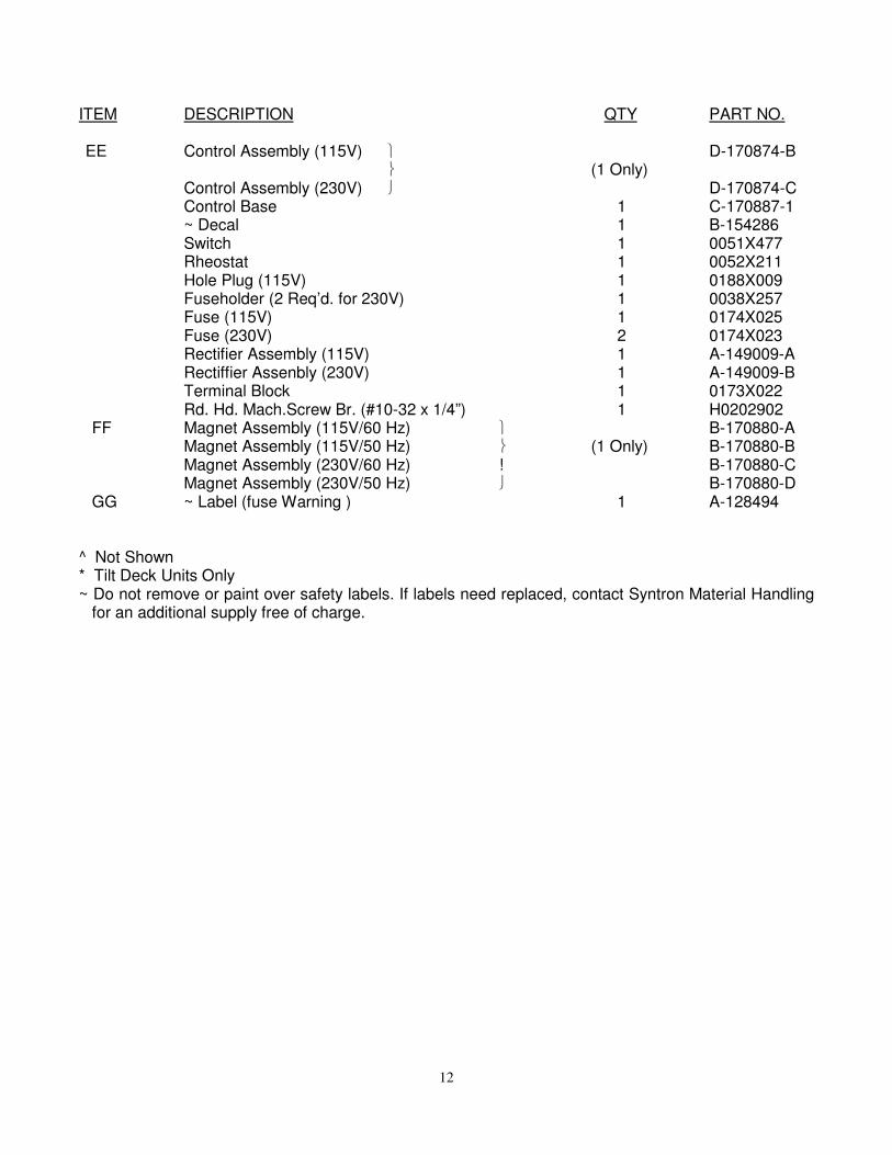
ITEM DESCRIPTION QTY PART NO. EE Control Assembly (115V) D-170874-B (1 Only) Control Assembly (230V) D-170874-C Control Base 1 C-170887-1 ~ Decal 1 B-154286 Switch 1 0051X477 Rheostat 1 0052X211 Hole Plug (115V) 1 0188X009 Fuseholder (2 Req’d. for 230V) 1 0038X257 Fuse (115V) 1 0174X025 Fuse (230V) 2 0174X023 Rectifier Assembly (115V) 1 A-149009-A Rectiffier Assenbly (230V) 1 A-149009-B Terminal Block 1 0173X022 Rd. Hd. Mach.Screw Br. (#10-32 x 1/4”) 1 H0202902 FF Magnet Assembly (115V/60 Hz) B-170880-A Magnet Assembly (115V/50 Hz) (1 Only) B-170880-B Magnet Assembly (230V/60 Hz) ! B-170880-C Magnet Assembly (230V/50 Hz) B-170880-D GG ~ Label (fuse Warning ) 1 A-128494 ^ Not Shown * Tilt Deck Units Only ~ Do not remove or paint over safety labels. If labels need replaced, contact Syntron Material Handling
for an additional supply free of charge.

13
Important
Syntron Material Handling reserves the right to alter at any time, without notice and without liability or
other obligations on its part, materials, equipment specifications, and models. Syntron Material
Handling also reserves the right to discontinue the manufacture of models, parts, and components
thereof.
Your satisfaction is very important to us. Please direct any comments, questions, or concerns to
our Marketing Communications Department.

Corporate Office
P.O. Box 1370 Tupelo, Mississippi 38802
Phone: 662.869.5711 Fax: 662.869.7449
Tupelo 2730 Hwy 145 South Saltillo, Mississippi 38866 Phone: 662.869.5711 Fax: 662.869.7493 Toll Free: 800.356.4898 [email protected]
Changshu #2 Road No. 1 Changshu Export Processing Zone Changshu, Jiangsu, China 215513 Phone: +86 0512.52299002 Fax: +86 0512.52297228 [email protected]
Form No. SM1120_011515 Printed in U.S.A