stackable fast ethernet switch - ネットギア … · processing equipment and electronic office...
TRANSCRIPT

FSM O D E L
517TS
FSM O D E L
524S
Stackable Fast Ethernet SwitchUser‘s Guide
ii
Trademarks
NETGEAR® is a registered trademark of NETGEAR, Inc. in the United States and other countries. All othertrademarks and registered trademarks are the property of their respective owners.
Statement of Conditions
In the interest of improving internal design, operational function, and/or reliability, NETGEAR reserves theright to make changes to the products described in this document without notice. NETGEAR does not assume any liability that may occur due to the use or application of the product(s) or circuit layout(s)described herein.
Certificate of the Manufacturer/Importer
It is hereby certified that the NETGEAR Model FS524S Stackable Fast Ethernet Switch and ModelFS517TS Stackable Fast Ethernet Switch with Gigabit Port have been suppressed in accordance with theconditions set out in the BMPT-AmtsblVfg 243/1991 and Vfg 46/1992.The operation of some equipment (forexample, test transmitters) in accordance with the regulations may, however, be subject to certain restrictions.Please refer to the notes in the operating instructions.
Federal Office for Telecommunications Approvals has been notified of the placing of this equipment on themarket and has been granted the right to test the series for compliance with the regulations.
Voluntary Control Council for Interference (VCCI) Statement
This equipment is in the first category (information equipment to be used in commercial and/or industrialareas) and conforms to the standards set by the Voluntary Control Council for Interference by DataProcessing Equipment and Electronic Office Machines that are aimed at preventing radio interference in commercial and/or industrial areas.
Consequently, when this equipment is used in a residential area or in an adjacent area thereto, radio interference may be caused to equipment such as radios and TV receivers.
Federal Communications Commission (FCC) Compliance Notice: Radio Frequency Notice
This device complies with part 15 of the FCC Rules. Operation is subject to the following two conditions:• This device may not cause harmful interference.• This device must accept any interference received, including interference that may cause
undesired operation.
Note: This equipment has been tested and found to comply with the limits for a Class A digital device,pursuant to part 15 of the FCC Rules.These limits are designed to provide reasonable protection against harmful interference in a residential installation.This equipment generates, uses, and can
iii
radiate radio frequency energy and, if not installed and used in accordance with the instructions, may cause harmful interference to radio communications. However, there is no guarantee that interference not occur in a particular installation. If this equipment does cause harmful interference to radio or television reception, which can be determined by turning the equipment off and on, the user is encouraged to try to correct the interference by one or more of the following measures:
• Reorient or relocate the receiving antenna.• Increase the separation between the equipment and receiver.• Connect the equipment into an outlet on a circuit different from that which the receiver is connected.• Consult the dealer or an experienced radio/TV technician for help.
EN 55 022 Declaration of Conformance
This is to certify that the NETGEAR Model FS524S Stackable Fast Ethernet Switch and Model FS517TSStackable Fast Ethernet Switch with Gigabit Port are shielded against the generation of radio interference inaccordance with the application of Council Directive 89/336/EEC, Article 4a. Conformity is declared by theapplication of EN 55024 Class A (CISPR 22).
Warning:This is a Class A product. In a domestic environment, this product may cause radio interference, in which case the user may be required to take appropriate measures.
Canadian Department of Communications Radio Interference Regulations
This digital apparatus (NETGEAR Model FS524S Stackable Fast Ethernet Switch and Model FS517TSStackable Fast Ethernet Switch with Gigabit Port) do not exceed the Class A limits for radio-noise emissions fromdigital apparatus as set out in the Radio Interference Regulations of the Canadian Department of Communications.
Règlement sur le brouillage radioélectrique du ministère des Communications
Cet appareil numérique (NETGEAR Model FS524S Stackable Fast Ethernet Switch and Model FS517TSStackable Fast Ethernet Switch with Gigabit Port) respecte les limites de bruits radioélectriques visant lesappareils numériques de classe A prescrites dans le Règlement sur le brouillage radioélectrique du ministèredes Communications du Canada.
!

iv
Customer Support
For assistance with installing and configuring your NETGEAR system or with questions or problems following installation:
• Check the NETGEAR Web page at http://www.NETGEAR.com.• Call Technical Support in North America at 1-888-NETGEAR. If you are outside North America, please
refer to the phone numbers listed on the Support Information Card that shipped with your switch.• Email Technical Support at [email protected].
Defective or damaged merchandise can be returned to your point-of-purchase representative.
Internet/World Wide Web
NETGEAR maintains a World Wide Web home page that you can access at the uniform resource locator(URL) http://www.NETGEAR.com. A direct connection to the Internet and a Web browser such as InternetExplorer or Netscape are required.
vContents
CONTENTS
CHAPTER 1Introduction 1-1Description 1-1Features 1-2
Unique Features 1-3Shared Features 1-4
Package Contents 1-5
CHAPTER 2Physical Description 2-1Front and Back Panels 2-110/100 Mbps RJ-45 Ports 2-3LED Descriptions 2-4
Power 2-4Stack 2-4Link 2-4FDX 2-417 ACT ( FS517TS only) 2-41000M (Port 17 on the FS517TS only) 2-4
Front Panel RJ-45 Gigabit Copper Port (FS517TS Only) 2-5Normal/Uplink Push Button (FS524S Only) 2-5Auto Uplink (FS517TS Only) 2-5
CHAPTER 3Applications 3-1Desktop Switching 3-1Segment Switching and Bridging from 10 Mbps to 100 Mbps 3-1Stacked Switching 3-2
contents vi
CHAPTER 4Installation 4-1Preparing the Site 4-2
Stacking 4-2Installing the Switch 4-3
Installing the Switch on a Flat Surface 4-3Installing the Switch in a Rack 4-3
Connecting Devices to the Switch 4-4Connecting Switches to the Stack’s Backplane 4-5Checking the Installation 4-8Applying AC Power 4-9
CHAPTER 5Troubleshooting 5-1Troubleshooting Chart 5-1Additional Troubleshooting Suggestions 5-3
Network Adapter Cards 5-3Configuration 5-3Switch Integrity 5-3Auto Negotiation 5-3
APPENDIX ATechnical Specifications A-1Network Protocol and Standards Compatibility A-1Data Rate A-1Interface A-1Electrical Specifications A-1Physical Specifications A-2Environmental Specifications A-2Electromagnetic Emissions A-2Electromagnetic Susceptibility A-3Safety Agency Approvals A-3Performance Specifications A-4
viicontents
APPENDIX BConnector Pin Assignments B-1RJ-45 Plug and RJ-45 Connector B-1
Normal Assignment on Ports 1 to 8 B-2Uplink Assignment on Port 8 B-2Channel B-2Description B-2
APPENDIX CCabling Guidelines C-1Fast Ethernet Cable Guidelines C-1Category 5 Cable C-2Category 5 Cable Specifications C-3Twisted Pair Cables C-4Patch Panels and Cables C-5Using 1000BASE-T Gigabit Ethernet over Category 5 Cable C-5
Overview C-5Cabling C-6Length C-6Return Loss C-6Patch Cables C-8Conclusion C-8
INDEX
figures viii
FIGURES
Figure 1-1. Package Contents 1-5
Figure 2-1. Front and Back Panels of the FS517TS Switch 2-2
Figure 2-2. Front and Back Panels of the FS524S Switch 2-3
Figure 2-3. Creating Redundant Paths between Network Devices (Example 1) 2-6
Figure 2-4. Creating Redundant Paths between Network Devices (Example 2) 2-7
Figure 3-1. Example of Desktop Switching 3-1
Figure 3-2. Example of Segment Switching and Bridging 3-2
Figure 3-3. Example of Switched Stacking 3-3
Figure 4-1. Attaching Mounting Brackets 4-4
Figure 4-2. Connecting Devices to the Switch 4-5
Figure 4-3. Cabling Two FS517TS Stacked Switches 4-7
Figure 4-4. Cabling FS524S Stacked Switches 4-7
Figure 4-5. Cabling FS517TS and FS524S Switches 4-8
ixtables
Figure B-1. RJ-45 Plug and RJ-45 Connectorwith Built-in LEDs B-1
Figure C-1. Straight-Through Twisted-Pair Cable C-4
Figure C-2. Crossover Twisted-Pair Cable C-4
Figure C-3. Category 5 UTP Cable with Male RJ-45 Plug at Each End C-5
TABLES
Table 2-1. Front Panel LEDs 2-4
Table 4-1. Site Requirements 4-2
Table 5-1. Troubleshooting Chart 5-1
Table B-1. 10/100 Mbps RJ-45 Plug and RJ-45 Connector Pin Assignments B-2
Table B-2. 100/1000 Mbps RJ-45 Plug and RJ-45 Connector Pin Assignments B-2
Table C-1. Electrical Requirements of Category 5 Cable C-3

1-1introduction
CHAPTER 1: INTRODUCTION
This installation guide describes the NETGEAR FS517TS and FS524S Stackable Fast Ethernet Switches.
The NETGEAR FS517TS and FS524S Switches are expandable, high-performanceIEEE-compliant network switches designed for users who want the high-speed perform-ance of 10/100 stacked switching to eliminate bottlenecks, boost performance, andincrease productivity.These switches are designed so that like models can stack to eachother (FS517TS to FS517TS or FS524S to FS524S) as well as to the other model(FS517TS to FS524S) to provide high-speed connections between switches.Additionally, the FS517TS includes a front panel 1000 Mbps (1Gbps) port to connectto other standards-based gigabit switches or servers, providing a high-speed connectionfrom your stack of switches to a server or your network backbone.To simplify installation,both switch models are shipped ready for use, with no configuration required. Everythingnecessary to stack these switches comes in the box, eliminating the need to purchaseadditional modules or kits.
This chapter provides the following information:
• Description
• Features
• Package contents
Description
The NETGEAR FS517TS and FS524S Stackable Fast Ethernet Switches are expand-able, powerful, and easy-to-use network solutions.The NETGEAR FS517TS Switchprovides 16 shielded RJ-45 network ports, while the NETGEAR FS524S Switch provides 24 shielded RJ-45 network ports.The FS517TS Switch also provides a frontpanel RJ-45 1000 Mbps (1 Gbps) copper port that can be used to create a high-per-formance backbone link.

introduction 1-2
All RJ-45 ports on the FS517TS and FS524S Switches automatically negotiate to thehighest speed, making the switches ideal for environments that have a mix of Ethernetand Fast Ethernet devices. In addition, all 10/100 Mbps ports operate in half- or full-duplex mode, increasing the maximum bandwidth of each connection up to 20 Mbps or200 Mbps, respectively. Both switch models support automatic address learning andIEEE 802.3x-compliant flow control to ensure optimal packet reliability.
The FS517TS and FS524S Switches can be free standing or rack mounted (in a wiringcloset or equipment room). Moreover, they can be used as stand-alone devices or cascaded to create a single “virtual” switch:
• The FS517TS Switch has a single stacking port that can cascade to another FS517TS Switch to provide a total of 32 Fast Ethernet ports and two copper gigabitports in a single switched stack.
• The FS524S Switch has two bi-directional stacking ports, allowing load-balanced,fault-tolerant, redundant connections when cascaded with other FS524S Switches.Up to eight FS524S Switches can be cascaded, providing up to 192 ports in a single switched stack via a 4 Gbps high-speed backplane.
• The FS517TS and FS524S Switches can be stacked together. Connecting two FS517TS Switches to a stack of eight FS524S creates one large virtual switch,with up to 224 Fast Ethernet ports and two copper gigabit ports for server or backbone connections.
Features
NETGEAR’s FS517TS and FS524S Switches share common features while providingtheir own unique benefits.The following sections describe the features that are uniqueand common to the switches.

1-3introduction
Unique Features
The FS517TS and FS524S Switches have the following unique key features:
Feature FS517TS Switch FS524S Switch
Number of 10/100 Mbps 16 24
RJ-45 ports per switch
Number of 1000 Mbps 1 0
RJ-45 ports per switch
Number of high-speed 1 2
stacking ports:
Maximum number of Two FS517TS Switches Eight FS524S Switches
switches in stack:
Maximum number of ports 32 or 224 (when eight 192 (eight cascaded FS524S
in stack FS524S Switches are added) Switches) or 224 (when two
FS517TS Switches are added)
Miscellaneous Front panel IEEE 802.3ab
1000BASE-T port for
easy expansion
Supports Auto UplinkTM, which Two bi-directional uplink ports
automatically configures the deliver 2 x 2 Gbps links between
RJ-45 ports for use with either switches
straight-through or crossover
cables to make the right
connection

introduction 1-4
Shared Features
The FS517TS and FS524S Switches share the following key features:
• Support wire-speed filtering and forwarding of the traffic on all ports
• Scale to meet your growing network needs, enabling performance to keep pace with port density
• Boast high-speed bandwidth over stacking connections
• Provide easy Plug-and-Play installation with no software to configure, for quick and easy connection to new or existing 10 and 100 Mbps users and services
• Support store-and-forward intelligent processing to remove erroneous packets from the network
• Support automatic address-learning function to build the packet-forwarding information table.The table contains up to 8,000 media access control (MAC) addresses (that is, the switch can support networks with as many as 8,000 devices).
• Autosense link speed (10 or 100 Mbps) and duplex mode (half- or full-duplex) to optimize connectivity and allow companies to migrate to Fast Ethernet one port at a time
• Support full-duplex mode to double throughput of point-to-point connections by enabling individual ports to transmit and receive data concurrently.
• Support IEEE 802.3x-compliant flow control to prevent dropped packets due to network back-ups and bottlenecks
• Comply with the IEEE802.3 Ethernet, IEEE802.3u Fast Ethernet standards, and IEEE802.3ab Gigabit Ethernet
• Provide LED indicators to show current switch status and simplify troubleshooting
• Rack Mount Kit provided for installing the switch in a standard 19-inch equipment rack or for mounting on the wall

1-5introduction
Package Contents
Figure 1-1 shows the package contents of the FS517TS and FS524S switches.
Figure 1-1. Package Contents
Verify that your package contains the following:
• FS517TS or FS524S Switch
• Rubber footpads for tabletop installation
• Power cord
• One stacking cable
• Rack-mount kit for installing the switch in a 19-inch rack
• This Installation Guide
• Support Information Card
• Warranty & Owner Registration Card
If any item is missing or damaged, contact your place of purchase immediately.

2-1physical description
CHAPTER 2: PHYSICAL DESCRIPTION
This chapter describes the hardware features of the FS517TS and FS524S Switches.Topics include:
• Front and back panels
• 10/100 Mbps RJ-45 ports
• LED descriptions
• Front panel RJ-45 Gigabit copper port (FS517TS Switch)
• Normal/Uplink push button
• Auto Uplink
Front and Back Panels
Figure 2-1 shows the key components on the front and back panels of the FS517TSSwitch. Figure 2-2 shows the key components on the front and back panels of theFS524S Switch.
The front panel of both switches contains LEDs and RJ-45 jacks.The front panel of theFS517TS Switch also contains a Gigabit copper port, while the front panel of theFS524S Switch contains a Normal/Uplink push button.
The FS517TS has Auto Uplink technology instead of a Normal/Uplink push button.
physical description 2-2
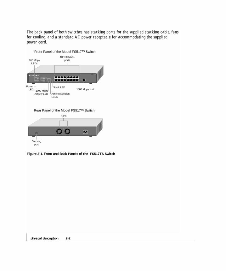
The back panel of both switches has stacking ports for the supplied stacking cable, fansfor cooling, and a standard AC power receptacle for accommodating the supplied power cord.
Figure 2-1. Front and Back Panels of the FS517TS Switch
100 MbpsLEDs
1000 MbpsActivity LED
10/100 Mbpsports
PowerLED
Stackingport
Stack LED1000 Mbps port
Activity/CollisionLEDs
Fans
Front Panel of the Model FS517TS Switch
Rear Panel of the Model FS517TS Switch

2-3physical description
Figure 2-2. Front and Back Panels of the FS524S Switch
10/100 Mbps RJ-45 Ports
As Figures 2-1 and 2-2 show, the FS517TS Switch has 16 RJ-45 ports, while theFS524S Switch has 24 RJ-45 ports.These ports are auto-sensing 10/100 Mbps ports:When you insert a cable into an RJ-45 port, the switch automatically ascertains themaximum speed (10 or 100 Mbps) and duplex mode (half- or full-duplex) of theattached device, and displays this information using the front panel 100 Mbps and FDXLEDs for that port (LEDs are described in the next section).The 10/100 Mbps portssupport only unshielded twisted-pair (UTP) cable terminated with an 8-pin RJ-45 plug.
100 MbpsLEDs
10/100 Mbpsports
PowerLED
Stackingports
Stack LEDs Normal/Uplinkpush buttonActivity/Collision LEDs
Fans
Front Panel of the Model FS524s Switch
Rear Panel of the Model FS524s Switch
physical description 2-4
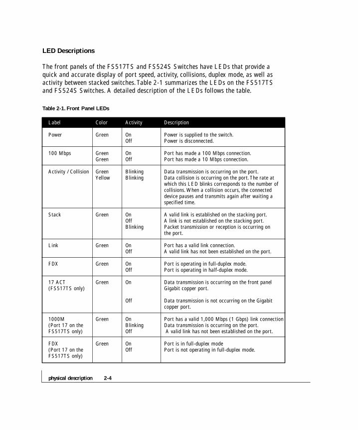
LED Descriptions
The front panels of the FS517TS and FS524S Switches have LEDs that provide aquick and accurate display of port speed, activity, collisions, duplex mode, as well asactivity between stacked switches.Table 2-1 summarizes the LEDs on the FS517TSand FS524S Switches. A detailed description of the LEDs follows the table.
Table 2-1. Front Panel LEDs
Label Color Activity Description
Power Green On Power is supplied to the switch.Off Power is disconnected.
100 Mbps Green On Port has made a 100 Mbps connection.Green Off Port has made a 10 Mbps connection.
Activity / Collision Green Blinking Data transmission is occurring on the port.Yellow Blinking Data collision is occurring on the port.The rate at
which this LED blinks corresponds to the number of collisions. When a collision occurs, the connected device pauses and transmits again after waiting a specified time.
Stack Green On A valid link is established on the stacking port.Off A link is not established on the stacking port.Blinking Packet transmission or reception is occurring on
the port.
Link Green On Port has a valid link connection.Off A valid link has not been established on the port.
FDX Green On Port is operating in full-duplex mode.Off Port is operating in half-duplex mode.
17 ACT Green On Data transmission is occurring on the front panel (FS517TS only) Gigabit copper port.
Off Data transmission is not occurring on the Gigabit copper port.
1000M Green On Port has a valid 1,000 Mbps (1 Gbps) link connection(Port 17 on the Blinking Data transmission is occurring on the port.FS517TS only) Off A valid link has not been established on the port.
FDX Green On Port is in full-duplex mode (Port 17 on the Off Port is not operating in full-duplex mode.FS517TS only)
2-5physical description
Front Panel RJ-45 Gigabit Copper Port (FS517TS Only)
The FS517TS Switch has a front panel RJ-45 Gigabit copper port.This port accommo-dates a Category 5 UTP cable with RJ-45 termination and provides a full-duplex 1000Mbps (1 Gbps) connection that effectively doubles throughput to 2 Gbps.
Normal/Uplink Push Button (FS524S Only)
The FS524S Switch has a Normal/Uplink push button on the front panel.This pushbutton lets you select uplink (MDI) or normal (MDI-X) wiring for port 24 on theFS524S Switch. Port 24 is configured for normal wiring to connect to a PC when thepush button is in the out position. Pressing the push button in configures port 24 foruplink wiring to connect to another switch or hub using a straight-through UTP cable.
Auto Uplink (FS517TS Only)
To simplify the procedure for attaching devices, all RJ-45 ports on the FS517TSSwitch support Auto Uplink.This technology allows you to attach devices to the RJ-45ports using either straight-through or crossover cables. When you insert a cable into theswitch’s RJ-45 port, the switch automatically:
• Senses whether the cable is a straight-through or crossover cable, and
• Determines whether the link to the attached device requires a “normal” connection (such as when connecting the port to a PC) or an “uplink” connection (such as when connecting the port to a router, switch, or hub).
After ascertaining this information, the switch automatically configures the RJ-45 portto enable communications with the attached device, without requiring user intervention.In this way, the Auto Uplink technology compensates for setting uplink connections,while eliminating concern about whether to use crossover or straight-through cableswhen attaching devices.

physical description 2-6
Note: Using Auto Uplink to create multiple active paths between any two network devices can cause undesirable loops in the network, resulting in an endless broadcast traffic that disables your network. Loops occur when there are alternate routes between two network devices. In Figure 2-3, for example, a loop is created by connecting two RJ-45 ports on an FS517TS Switch to a router containing a 4-port switch. Figure 2-4 shows another scenario where a router with a 4-port switch connects to a hub and to a FS517TS Switch; the hub and switch, in turn, connect back to the same router, creating multiple active paths between all three devices.
Figure 2-3.Warning! Creating loops disables your network (Example 1)
Model FS517TS Switch
FR314 Router

2-7physical description
Figure 2-4.Warning! Creating loops disables your network (Example 2)
Model FS517TS SwitchEN524 Hub
FR314 Router


3-1applications
CHAPTER 3: APPLICATIONS
The FS517TS and FS524S Switches are designed to provide flexibility in configuringyour network connections. Both switches can be used as stand-alone devices or usedwith 10 Mbps hubs, 100 Mbps hubs, or 10/100 Mbps switches.They can also bestacked to create one large virtual switch.This chapter shows how the FS517TS andFS524S Switches can be used in various network environments.
Topics include:
• Desktop switching
• Segment switching and bridging from 10 Mbps to 100 Mbps
Desktop Switching
The FS517TS and FS524S Switches can be used as desktop switches to build a smallnetwork that enables users to have 100 Mbps access to a file server. If a full-duplexadapter card is installed in the server or PC, the switch port connected to the server orPC can provide 200 Mbps full-duplex connection.
Figure 3-1. Example of Desktop Switching
100 Mbps1000 Mbps
10 Mbps
Model FS524S
Switch
Model FS517TS
Switch
Server Server

applications 3-2
Segment Switching and Bridging from 10 Mbps to 100 Mbps
The FS517TS and FS524S Switches can be used to segment a network into multipleconnected pieces to increase overall bandwidth and throughput. Both switch models cansegment networks that are built with the NETGEAR DS508 and EN516 hubs, and canact as bridges connecting traditional 10BASE-T Ethernet networks to 100BASE-TXFast Ethernet networks.
Figure 3-2. Example of Segment Switching and Bridging
Stacked Switching
The FS517TS and FS524S Switches can provide a full-duplex, switched network forlarge numbers of users by stacking units together.
• The FS517TS Switch has a single stacking port that can cascade another FS517TS Switch.This configuration provides a total of 32 10/100 Mbps ports and two gigabit ports in a single switched stack.The high-speed stacking ports deliver 2 Gbps of throughput across the stacking back plane.
Model FS524S Switch
Model EN516Hub
Model FR314Router
Model DS508Hub

3-3applications
• The FS524S Switch has two bi-directional stacking ports, which allow load-balanced,fault-tolerant, redundant connections when cascaded with another FS524S Switch.Up to eight FS524S Switches can be cascaded, providing up to 192 ports in a single switched stack.The high-speed stacking ports deliver 4 Gbps of throughput across thestacking back plane.
To add gigabit connectivity, two FS517TS Switches can be added to the stack to create one large virtual switch with up to 224 stacked ports and two 1000BASE-T ports. Since the FS517TS Switch has a single stacking port, adding it to a stack of FS524S Switches reduces the stacking backplane speed to 2 Gbps and removes support for load balancing, fault tolerance, and redundancy that a pure FS524Sstack has.
Figure 3-3. Example of Switched Stacking
Internet FS517TS Switch
FS517TS Switch
10 Mbps
1000 Mbps
DSL modem
FR314 Router
PS113 Print Server
Printer PrinterPC PC PC MAC
Servers
Servers
100 Mbps
FS524S Switch
FS524S Switch


4-1installation
CHAPTER 4: INSTALLATION
This chapter describes the installation procedures for the NETGEAR FS517TS andFS524S Switches.Topics include:
• Preparing the site
• Installing the switch
• Connecting devices to the switch
• Stacking switches
• Checking the installation
• Applying AC power

installation 4-2
Preparing the Site
Before you install your switch, be sure your operating environment meets the operatingenvironment requirements in Table 4-1.
Table 4-1. Site Requirements
Characteristics Requirements
MountingDesktop installations: Provide a flat table or shelf surface.
Rack-mount installations: Use a 19-inch (48.3-centimeter) EIA standard equipment rack that is grounded and physically secure. You also need the rack-mount kit supplied with your switch.
Access Locate the switch in a position that lets you access the front panel RJ-45 ports, view the front panel LEDs, and access the rear-panel stacking port(s) and power connector.
Power source Provide a power source within 6 feet (1.8 meters) of the installation location. Power specifications for the switches are shown in Appendix A. Be sure the AC outlet is not controlled by a wall switch, which can accidentally turn off power to the outlet and the switch.
EnvironmentalInstall the switch in a dry area, with ambient temperature between 0 and
Temperature: 40ºC (32 and 104ºF). Keep the switch away from heat sources such as direct sunlight, warm air exhausts, hot-air vents, and heaters.
Operating humidity: The installation location should have a maximum relative humidity of 90%, non-condensing.
Ventilation: Do not restrict airflow by covering or obstructing air inlets on the sides of the switch. Keep at least 2 inches (5.08 centimeters) free on all sides for cooling. Be sure there is adequate airflow in the room or wiring closet where you intend to install the switch.
Operating conditions: Keep the switch at least 6 ft (1.83 m) away from nearest source of electromagnetic noise, such as a photocopy machine.
Stacking If you intend to stack two or more switches, be sure the mounting surface can safely support the switch stack. Also, be sure there is adequate space around the stack for ventilation and cooling.
After confirming that your site meets the requirements in Table 4-1, you are ready toinstall the switch.

4-3installation
Installing the Switch
You can install the NETGEAR FS517TS and FS524S Switches on a flat surface or ina standard 19-inch rack.
Installing the Switch on a Flat Surface
1.The switch ships with four self-adhesive rubber footpads. Stick one rubber foot pad on each of the four concave spaces on the bottom of the switch.The rubber foot pads cushion the switch against shock/vibrations.They also provide space between each stacked switch for ventilation.
2.To stack switches:
• Repeat step 1 for each switch to be stacked.
• Place the first switch on a firm flat surface where you want to install the stack.Stack the other switches on top of this unit.
• Proceed to “Connecting Switches to the Stack’s Backplane” on page 21.
Installing the Switch in a Rack
To install the FS517TS or FS524S Switch in a rack, use the following procedure (andrefer to Figure 4-1).To perform this procedure, you need the 19-inch rack-mount kitsupplied with your switch.
1.Attach the supplied mounting brackets to the side of the switch.
2.Insert the screws provided in the rack-mount kit through each bracket and into the bracket mounting holes in the switch.
3.Tighten the screws with a #1 Phillips screwdriver to secure each bracket.
4. Align the mounting holes in the brackets with the holes in the rack, and insert two pan-head screws with nylon washers through each bracket and into the rack.

installation 4-4
5.Tighten the screws with a #2 Phillips screwdriver to secure the switch in the rack.
6. Proceed to “Connecting Devices to the Switch.”
Figure 4-1. Attaching Mounting Brackets
Connecting Devices to the Switch
The following procedure describes how to connect devices to the switch’s RJ-45 ports.When attaching devices to the FS517TS, the switch’s support for Auto Uplink technol-ogy allows you to attach devices using either straight-through or crossover cables (formore information about Auto LinkTM technology, refer to “Auto Uplink (FS517TS)”on page 2-5).
1.Connect each device to an RJ-45 network port on the switch’s front panel (see Figure 4-2). Use Category 5 (Cat5) unshielded twisted-pair (UTP) cable terminated with an RJ-45 connector to make these connections.
Note: Ethernet specifications limit the cable length between the switch and the attached device to 100 m (328 ft).
MODEL
4-5introduction
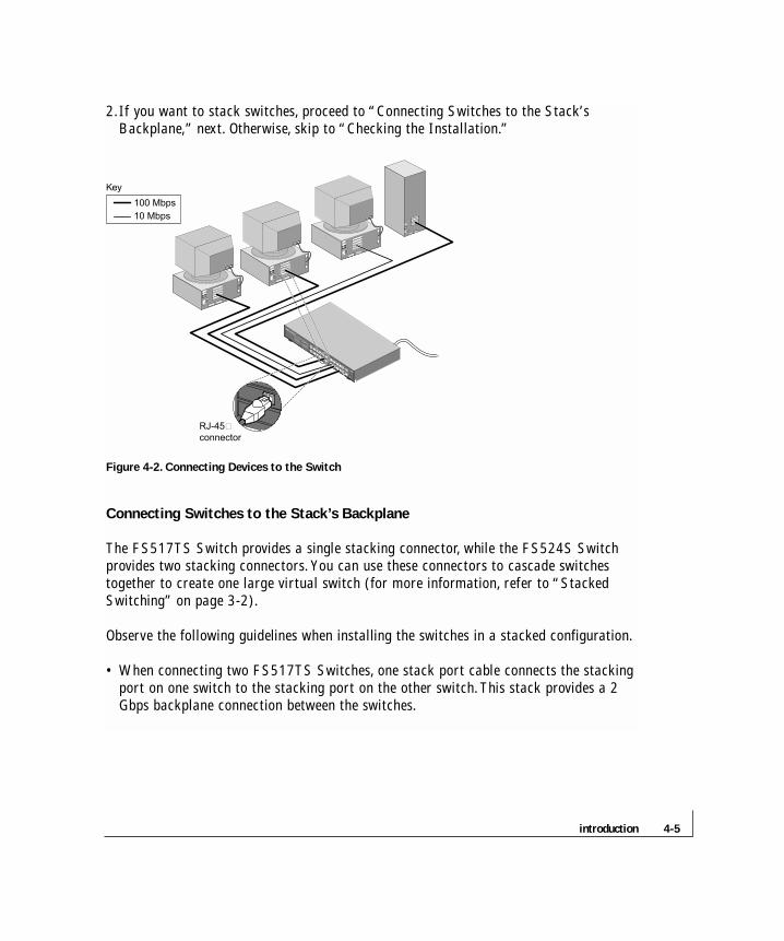
2.If you want to stack switches, proceed to “Connecting Switches to the Stack’s Backplane,” next. Otherwise, skip to “Checking the Installation.”
Figure 4-2. Connecting Devices to the Switch
Connecting Switches to the Stack’s Backplane
The FS517TS Switch provides a single stacking connector, while the FS524S Switchprovides two stacking connectors. You can use these connectors to cascade switchestogether to create one large virtual switch (for more information, refer to “StackedSwitching” on page 3-2).
Observe the following guidelines when installing the switches in a stacked configuration.
• When connecting two FS517TS Switches, one stack port cable connects the stackingport on one switch to the stacking port on the other switch.This stack provides a 2 Gbps backplane connection between the switches.
100 Mbps
RJ-45connector
Key
10 Mbps
installation 4-6
• When connecting two FS524S Switches, two stack port cables connect the stacking ports on one switch to the stacking ports on the other switch.This stack provides a bi-directional, load-balanced, fault-tolerant, redundant connection between the stacked switches, with a backplane speed of 4 Gbps.
• When connecting FS524S and FS517TS, one stack port cable connects the stacking port on one switch to the stacking port on the other switch.This stack provides a 2 Gbps backplane connection between the switches.
• The Stack port cable connection is “hot-swappable.”This means you can disconnect and reconnect the stacking cable when power to the switches is on.
• To prevent bent pins, do not install the stack port cable connector at an angle. Use extra care to insert the cable connector straight into the switch’s stacking connector.
To stack switches, use the following procedure:
1.Connect one end of the stack port cable to the stacking port on one switch. It does not matter which end of the cable to use. Either end of the stack port cable can be connected to either one of the switches.
2.Connect the other end of the cable to the stack port on the other switch.
3.If you are connecting FS524S Switches, repeat steps 1 and 2 to connect the second stacking connector on each switch.
Figure 4-3 shows the cabling for a stack of two FS517TS Switches. Figure 4-4 showsthe cabling for a stack of multiple FS524S Switches. Figure 4-5 shows the cabling fora stack of FS524S Switches that includes an FS517TS Switch.

4-7installation
Figure 4-3. Cabling Two FS517TS Stacked Switches
Figure 4-4. Cabling FS524S Stacked Switches
Two Model FS517TS Switches
Two Model FS524S Switches
Eight Model FS524S Switches

installation 4-8
Figure 4-5. Cabling FS517TS and FS524S Switches
Checking the Installation
Before you apply power:
• Inspect the equipment thoroughly.
• Verify that all cables are installed correctly.
• Check cable routing to make sure cables are not damaged or create a safety hazard.
• Be sure all equipment is mounted properly and securely.
Model FS524S
Switches
Model FS517TS Switch
Model FS517TS Switch
4-9installation
Applying AC Power
The switches do not have an ON/OFF switch; the only method of applying or removingAC power is by connecting or disconnecting the power cord. Before you connect thepower cord, select an AC outlet that is not controlled by a wall switch, which can turnoff power to the switch. After you select an appropriate outlet, use the following procedure to apply AC power.
1.Connect the female end of the supplied AC power adapter cable to the power outlet on the back of the switch.
2.Connect the 3-pronged end of the AC power adapter cable to a grounded 3-pronged AC outlet.
When you apply power:
• The green Power LED on the switch’s front panel goes on.
• The green Link LED on each connected RJ-45 port goes on.
If the green Power LED does not go on, check that the power cable is plugged in correctly and that the power source is good. If this does not resolve the problem,refer to Chapter 5,Troubleshooting.
When power is applied, the switch conducts a power-on self-test (POST) to verify operation. After the switch passes the POST, it is functional and ready to pass data.

5-1troubleshooting
CHAPTER 5:TROUBLESHOOTING
This chapter provides information about troubleshooting the NETGEAR FS517TS orFS524S Switches.Topics include:
• Troubleshooting chart• Additional troubleshooting suggestions
Troubleshooting Chart
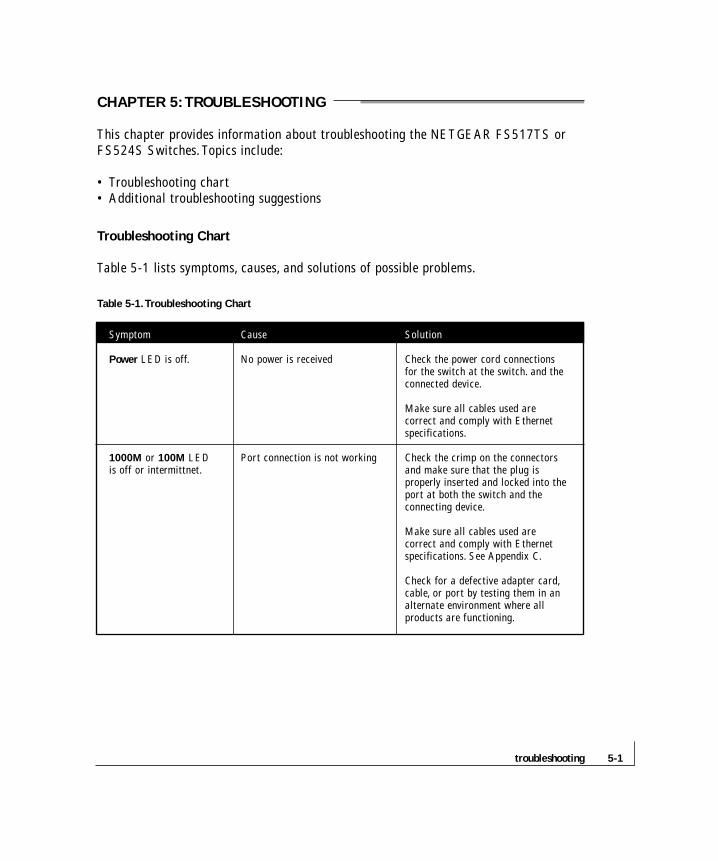
Table 5-1 lists symptoms, causes, and solutions of possible problems.
Table 5-1.Troubleshooting Chart
Symptom Cause Solution
Power LED is off. No power is received Check the power cord connections for the switch at the switch. and the connected device.
Make sure all cables used are correct and comply with Ethernet specifications.
1000M or 100M LED Port connection is not working Check the crimp on the connectors is off or intermittnet. and make sure that the plug is
properly inserted and locked into the port at both the switch and the connecting device.
Make sure all cables used are correct and comply with Ethernet specifications. See Appendix C.
Check for a defective adapter card,cable, or port by testing them in an alternate environment where all products are functioning.

troubleshooting 5-2
Symptom Cause Solution
Link LED is off for a port There is a problem with this Make sure the cable is attached that has a connection. connection. securely at both ends.
Make sure the cable is not damaged.
Check that the device being connected to is powered on and operating correctly.
If the connection is to a workstation,make sure the workstation’s network interface is installed and configured correctly.
File transfer is slow or Half- or full-duplex setting on Make sure the attached device is set to performance degradation the switch and the connected auto negotiate.is a problem. device are not the same.
A segment or device is One or more devices are not Verify that the cabling is correct. Be not recognized as part properly connected, or sure all connectors are securely of the network. cabling does not meet positioned in the required ports.
Ethernet guidelines. Equipment may have been accidentally disconnected.
FDX/COL LED is Collisions are occurring Some collisions are normal when blinking yellow on the connected segment. the connection is operating in excessively. half-duplex mode.
Duplex modes are mismatched. Recheck the settings of the device attached to the RJ-45 port. Make sure the attached device is set to auto negotiate.
ACT LED is flashing A network loop (redundant path) Break the loop by ensuring that there continuously on all has been created is only one path from any networked connected ports and the (see Figures 2-3 and 2.4). device to any other networked device.network is disabled
5-3troubleshooting
Additional Troubleshooting Suggestions
If the suggestions in Table 5-1 do not resolve your problem, refer to the troubleshootingsuggestions in this section.
Network Adapter Cards
Make sure the network adapter cards installed in the PCs are in working condition andthe software driver has been installed.
Configuration
If problems occur after altering the network configuration, restore the original connec-tions and determine the problem by implementing the new changes, one step at a time.Make sure that cable distances, repeater limits, and other physical aspects of the instal-lation do not exceed the Ethernet limitations.
Switch Integrity
If required, verify the integrity of the switch by resetting the switch.To reset the switch,remove AC power from the switch and then reapply AC power. If the problem continues,contact NETGEAR technical support. In North America, call 1-888-NETGEAR. If youare outside of North America, please refer to the support information card includedwith your product.
Auto Negotiation
The 10/100 Mbps ports negotiate the correct duplex mode and speed if the device atthe other end of the link supports auto negotiation. If the device does not support autonegotiation, the switch only determines the speed correctly and the duplex modedefaults to half-duplex.
The gigabit port on the FS517TS Switch negotiates speed, duplex mode, and flow control, provided that the attached device supports auto-negotiation.


A-1technical specifications
APPENDIX A:TECHNICAL SPECIFICATIONS
This appendix provides technical specifications for the NETGEAR FS517TS orFS524S Switches.
Network Protocol and Standards Compatibility
ISO/IEC 802-3i 10BASE-T
IEEE 802.3u 100BASE-TX
IEEE 802.3ab 1000BASE-T
IEEE 802.3x Flow Control
Data Rate
10 Mbps differential Manchester encoded, IEEE 802.3
100 Mbps with 4B/5B encoding and MLT-3 physical interface for 100BASE-TX
1000 Mbps with 8B/10B encoding PAM-5 physical interface for 1000BASE-T
Interface
RJ-45 connector for 10BASE-T, 100BASE-TX Fast Ethernet, and 1000BASE-TGigabit Ethernet
Electrical Specifications
Power consumption: 45 W maximum
technical specifications A-2
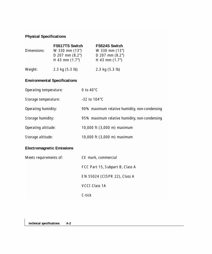
Physical Specifications
FS517TS Switch FS524S SwitchDimensions: W 330 mm (13") W 330 mm (13")
D 207 mm (8.2") D 207 mm (8.2")H 43 mm (1.7") H 43 mm (1.7")
Weight: 2.3 kg (5.3 lb) 2.3 kg (5.3 lb)
Environmental Specifications
Operating temperature: 0 to 40°C
Storage temperature: -32 to 104°C
Operating humidity: 90% maximum relative humidity, non-condensing
Storage humidity: 95% maximum relative humidity, non-condensing
Operating altitude: 10,000 ft (3,000 m) maximum
Storage altitude: 10,000 ft (3,000 m) maximum
Electromagnetic Emissions
Meets requirements of: CE mark, commercial
FCC Part 15, Subpart B, Class A
EN 55024 (CISPR 22), Class A
VCCI Class 1A
C-tick
A-3technical specifications
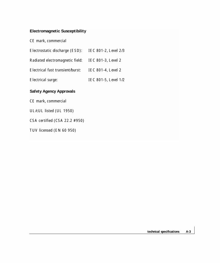
Electromagnetic Susceptibility
CE mark, commercial
Electrostatic discharge (ESD): IEC 801-2, Level 2/3
Radiated electromagnetic field: IEC 801-3, Level 2
Electrical fast transient/burst: IEC 801-4, Level 2
Electrical surge: IEC 801-5, Level 1/2
Safety Agency Approvals
CE mark, commercial
UL/cUL listed (UL 1950)
CSA certified (CSA 22.2 #950)
TUV licensed (EN 60 950)
connector pin assignments A-4
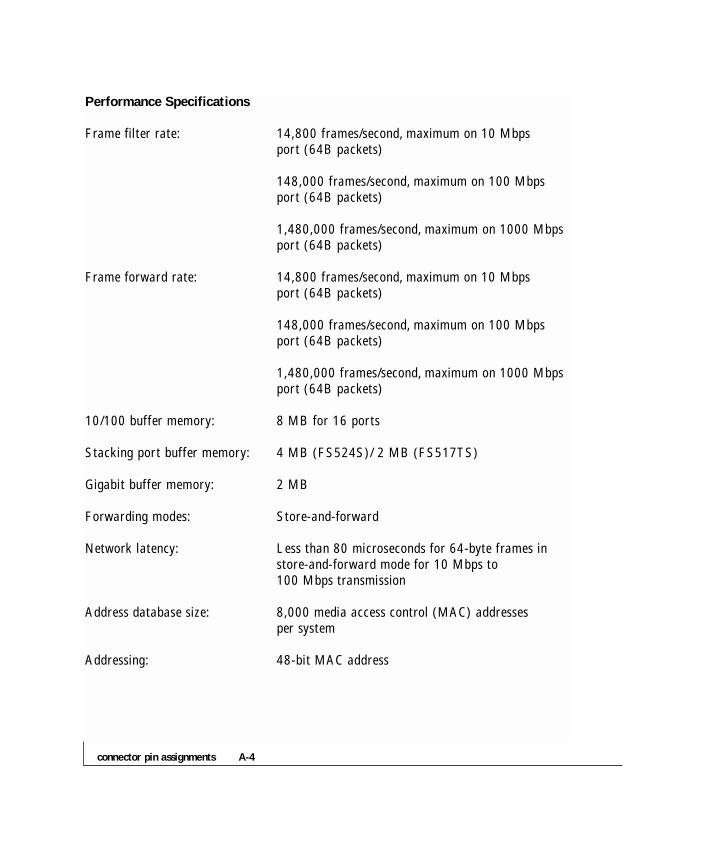
Performance Specifications
Frame filter rate: 14,800 frames/second, maximum on 10 Mbpsport (64B packets)
148,000 frames/second, maximum on 100 Mbps port (64B packets)
1,480,000 frames/second, maximum on 1000 Mbps port (64B packets)
Frame forward rate: 14,800 frames/second, maximum on 10 Mbps port (64B packets)
148,000 frames/second, maximum on 100 Mbps port (64B packets)
1,480,000 frames/second, maximum on 1000 Mbps port (64B packets)
10/100 buffer memory: 8 MB for 16 ports
Stacking port buffer memory: 4 MB (FS524S)/ 2 MB (FS517TS)
Gigabit buffer memory: 2 MB
Forwarding modes: Store-and-forward
Network latency: Less than 80 microseconds for 64-byte frames in store-and-forward mode for 10 Mbps to 100 Mbps transmission
Address database size: 8,000 media access control (MAC) addresses per system
Addressing: 48-bit MAC address

B-1connector pin assignments
APPENDIX B: CONNECTOR PIN ASSIGNMENTS
This appendix provides information about the RJ-45 plug and the RJ-45 connector usedfor the NETGEAR FS524S and FS517TS Switches.
RJ-45 Plug and RJ-45 Connector
In a Fast Ethernet network, it is important that all 100BASE-T certified Category 5cabling use RJ-45 plugs.The RJ-45 plug accepts 4-pair UTP or shielded twisted-pair(STP) 100 ohm cable and connects into the RJ-45 connector.The RJ-45 connector isused to connect stations, hubs, and switches through UTP cable; it supports 10 Mbps,100 Mbps, or 1000 Mbps data transmission.
Figure B-1 shows the RJ-45 plug and RJ-45 connector.
Figure B-1. RJ-45 Plug and RJ-45 Connector with Built-in LEDs
Key:1 to 8 = pin numbers
711EA
18
12345678
technical specifications B-2
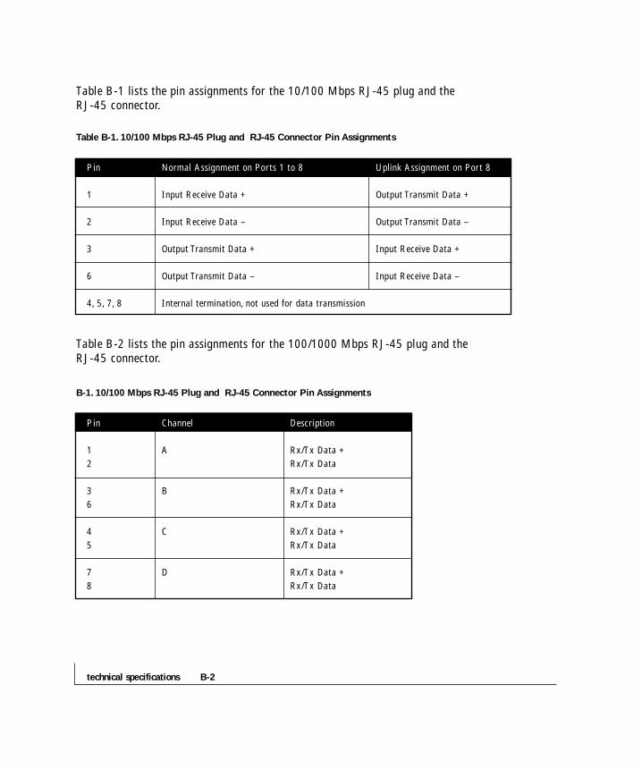
Table B-1 lists the pin assignments for the 10/100 Mbps RJ-45 plug and the RJ-45 connector.
Table B-1. 10/100 Mbps RJ-45 Plug and RJ-45 Connector Pin Assignments
Pin Normal Assignment on Ports 1 to 8 Uplink Assignment on Port 8
1 Input Receive Data + Output Transmit Data +
2 Input Receive Data – Output Transmit Data –
3 Output Transmit Data + Input Receive Data +
6 Output Transmit Data – Input Receive Data –
4, 5, 7, 8 Internal termination, not used for data transmission
Table B-2 lists the pin assignments for the 100/1000 Mbps RJ-45 plug and the RJ-45 connector.
B-1. 10/100 Mbps RJ-45 Plug and RJ-45 Connector Pin Assignments
Pin Channel Description
1 A Rx/Tx Data +
2 Rx/Tx Data
3 B Rx/Tx Data +
6 Rx/Tx Data
4 C Rx/Tx Data +
5 Rx/Tx Data
7 D Rx/Tx Data +
8 Rx/Tx Data
C-1cabling guidelines
APPENDIX C: CABLING GUIDELINES
This appendix provides specifications for cables used with the FS524S and FS517TS Switches.
Fast Ethernet Cable Guidelines
Fast Ethernet uses UTP cable, as specified in the IEEE 802.3u standard for100BASE-TX.The specification requires Category 5 UTP cable consisting of eithertwo-pair or four-pair twisted insulated copper conductors bound in a single plasticsheath. Category 5 cable is certified up to 100 MHz bandwidth. 100BASE-TX operation uses one pair of wires for transmission and the other pair for receiving andfor collision detection.
When installing Category 5 UTP cabling, use the following guidelines to ensure thatyour cables perform to the following specifications:
• Certification
Make sure that your Category 5 UTP cable has completed the Underwriters’Laboratories (UL) or Electronic Testing Laboratories (ETL) certification process.
• Termination method
To minimize cross-talk noise, maintain the twist ratio of the cable up to the point of termination; untwist at any RJ-45 plug or patch panel should not exceed 0.5 inch (1.5 cm).

cabling guidelines C-2
Category 5 Cable
Category 5 distributed cable that meets ANSI/EIA/TIA-568-A building wiring standards can be a maximum of 328 feet (ft) or 100 meters (m) in length, divided as follows:
• 20 ft (6 m) between the hub and the patch panel (if used)
• 295 ft (90 m) from the wiring closet to the wall outlet
• 10 ft (3 m) from the wall outlet to the desktop device
The patch panel and other connecting hardware must meet the requirements for 100Mbps operation (Category 5). Only 0.5 inch (1.5 cm) of untwist in the wire pair isallowed at any termination point.

C-3cabling guidelines
Category 5 Cable Specifications
Ensure that the fiber cable is crossed over to guarantee link.
Table C-1 lists the electrical requirements of Category 5 UTP cable.
Table C-1. Electrical Requirements of Category 5 Cable
Specifications Category 5 Cable Requirements
Number of pairs Four
Impedance 100 Ω ± 15%
Mutual capacitance at 1 KHz ≤5.6 nF per 100 m
Maximum attenuation
(dB per 100 m, at 20° C) at 4 MHz: 8.2
at 31 MHz: 11.7
at 100 MHz: 22.0
NEXT loss (dB minimum) at 16 MHz: 44
at 31 MHz: 39
at 100 MHz: 32
Twisted Pair Cables
For two devices to communicate, the transmitter of each device must be connected tothe receiver of the other device.The crossover function is usually implemented internallyas part of the circuitry in the device. Computers and workstation adapter cards are usually media-dependent interface ports, called MDI or uplink ports. Most repeatersand switch ports are configured as media-dependent interfaces with built-in crossoverports, called MDI-X or normal ports.

cabling guidelines C-4
Figure C-1 illustrates straight-through twisted pair cable.
Figure C-1. Straight-Through Twisted-Pair Cable
Figure C-2 illustrates crossover twisted pair cable.
Figure C-2. Crossover Twisted-Pair Cable
736EA
Tx
Rx
1
2
3
6Tx
Rx1
2
3
6
A B
Key:A = Uplink or MDI port (as on a PC)B = Normal or MDI-X port (as on a hub or switch)1, 2, 3, 6 = Pin numbers
737EA
B B
1
2
3
6
1
2
3
6Tx
Rx
Tx
Rx
Key:B = Normal or MDI-X port (as on a hub or switch)1, 2, 3, 6 = Pin numbers
C-5cabling guidelines
Patch Panels and Cables
If you are using patch panels, make sure that they meet the 100BASE-TX requirements.NETGEAR recommends Category 5 UTP cable for all patch cables and work areacables to ensure that your UTP patch cable rating meets or exceeds the distributioncable rating.
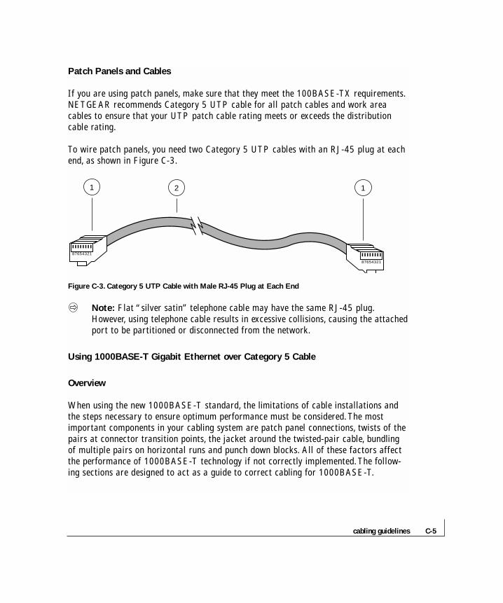
To wire patch panels, you need two Category 5 UTP cables with an RJ-45 plug at eachend, as shown in Figure C-3.
Figure C-3. Category 5 UTP Cable with Male RJ-45 Plug at Each End
Note: Flat “silver satin” telephone cable may have the same RJ-45 plug.However, using telephone cable results in excessive collisions, causing the attachedport to be partitioned or disconnected from the network.
Using 1000BASE-T Gigabit Ethernet over Category 5 Cable
Overview
When using the new 1000BASE-T standard, the limitations of cable installations andthe steps necessary to ensure optimum performance must be considered.The mostimportant components in your cabling system are patch panel connections, twists of thepairs at connector transition points, the jacket around the twisted-pair cable, bundlingof multiple pairs on horizontal runs and punch down blocks. All of these factors affectthe performance of 1000BASE-T technology if not correctly implemented.The follow-ing sections are designed to act as a guide to correct cabling for 1000BASE-T.
87654321
87654321
2 11

cabling guidelines C-6
Cabling
The 1000BASE-T product is designed to operate over Category 5 cabling.To furtherenhance the operation, the cabling standards have been amended.The latest standard isCategory 5e, which defines a higher level of link performance than is available withCategory 5 cable.
If installing new cable, we recommend using Category 5e cable, since it costs about thesame as Category 5 cable. If using the existing cable, be sure to have the cable planttested by a professional who can verify that it meets or exceeds either ANSI/EIA/TIA-568-A:1995 or ISO/IEC 11801:1995 Category 5 specifications.
Length
The maximum distance limitation between two pieces of equipment is 100 m, as per theoriginal Ethernet specification.The end-to-end link is called the “channel.”
TSB-67 defines the “Basic Link” which is the portion of the link that is part of thebuilding infrastructure.This excludes patch and equipment cords.The maximum basiclink length is 295 feet (90 m).
Return Loss
Return loss measures the amount of reflected signal energy resulting from impedancechanges in the cabling link.The nature of 1000BASE-T renders this measurement veryimportant; if too much energy is reflected back on to the receiver, the device does notperform optimally.
Unlike 10BASE-T and 100BASE-TX, which use only two of the four pairs of wireswithin the Category 5, 1000BASE-T uses all four pairs of the twisted pair. Make sureall wires are tested æ this is important.
C-7cabling guidelines
Factors that affect the return loss are:
• The number of transition points, as there is a connection via an RJ-45 to another connector, a patch panel, or device at each transition point.
• Removing the jacket that surrounds the four pairs of twisted cable. It is highly recommended that, when RJ-45 connections are made, this is minimized to 1-1/4 inch (32 mm).
• Untwisting any pair of the twisted-pair cabling. It is important that any untwisting beminimized to 3/8 inch (10 mm) for RJ-45 connections.
• Cabling or bundling of multiple Category 5 cables.This is regulated by ANSI/EIA/TIA-568A-3. If not correctly implemented, this can adversely affect all cabling parameters.
Near End Cross Talk (NEXT)
This is a measure of the signal coupling from one wire to another, within a cable assembly,or among cables within a bundle. NEXT measures the amount of cross-talk disturbanceenergy that is detected at the near end of the link — the end where the transmitter islocated. NEXT measures the amount of energy that is “returned” to the sender end.Thefactors that affect NEXT and cross talk are exactly the same as outlined in the ReturnLoss section.The cross-talk performance is directly related to the quality of the cable installation.

cabling guidelines C-8
Patch Cables
When installing your equipment, replace old patch panel cables that do not meetCategory 5e specifications. As pointed out in the NEXT section, this near end piece ofcable is critical for successful operation.
Conclusion
For optimum performance of your 1000BASE-T product, it is important to fully qualifyyour cable installation and ensure it meets or exceeds ANSI/EIA/TIA-568-A:1995 orISO/IEC 11801:1995 Category 5 specifications. Install Category 5e cable where possi-ble, including patch panel cables. Minimize transition points, jacket removal, and untwistlengths. Bundling of cables must be properly installed to meet the requirements inANSI/EIA/TIA-568A-3.
1-1index
A
Applications
Desktop Switching, 3-1
Segment Switching and Bridging
from Mbps to 100 Mbps, 3-2
Stacked Switching, 3-2
Applying AC Power, 4-9
Auto Uplink (FS517TS Only), 2-5
C
Cabling guidelines
Fast Ethernet Cable Guidelines, C-1
Category 5 Cable, C-2
Category 5 Cable Specifications, C-3
Twisted Pair Cables, C-3
Patch Panels and Cables, C-5
Using 1000BASE-T Gigabit Ethernet
over Category 5 Cable, C-5
Cabling, C-6
Length, C-6
Return Loss, C-6
Near End Cross Talk (NEXT), C-7
Patch Cables, C-8
Conclusion, C-8
Checking the Installation, 4-8
Connecting Devices to the Switch, 4-4
Connecting Switches to the
Stack’s Backplane, 4-5
Connector pin assignments
RJ-45 Plug and RJ-45 Connector, B-1
Customer Support, iv
D
Date Rate, A-1
Desktop Switching, 3-1
F
Fast Ethernet Cable Guidelines, C-1
Features, 1-2
Front and Back Panels, 2-1
Front Panel RJ-45 Gigabit Port
(FS517TS Only), 2-5
I
Installation
Preparing the Site, 4-1
Installing the Switch, 4-3
Installing the Switch on a
Flat Surface, 4-3
Installing the Switch in a Rack, 4-3
Connecting Devices to the Switch, 4-4
Connecting Switches to the
Stack’s Backplane, 4-5
Checking the Installation, 4-8
Applying AC Power, 4-9
Interface, A-1
L
LED Descriptions, 2-4
N
Near End Cross Talk (NEXT), C-7
Network Protocol and
Standards Compatibility, A-1
Normal/Uplink Push Button
(FS524S Only), 2-5

index 1-2
P
Package Contents, 1-5
Patch Panels and Cables, C-5
Physical Description
Front and Back Panels, 2-1
10/100 Mbps RJ-45 Ports, 2-3
LED Descriptions, 2-4
Front Panel RJ-45 Gigabit Port
(FS517TS Only), 2-5
Normal/Uplink Push Button
(FS524S Only), 2-5
Auto Uplink (FS517TS Only), 2-5
Preparing the Site, 4-2
R
Return Loss, C-6
RJ-45 Plug and RJ-45 Connector, B-1
S
Segment Switching and Bridging
from Mbps to 100 Mbps, 3-2
Shared Features, 1-4
Stacked Switching, 3-2
T
Technical Specifications
Network Protocol and
Standards Compatibility, A-1
Date Rate, A1
Interface, A1
Electrical Specifications, A1
Physical Specifications, A2
Environmental Specifications, A-2
Electromagnetic Emissions, A-2
Electromagnetic Susceptibility, A-3
Safety Agency Approvals, A-3
Performance Specifications, A-4
Troubleshooting
Troubleshooting Chart, 5-1
Additional Troubleshooting
Suggestions, 5-3
Network Adapter Cards, 5-3
Configuration, 5-3
Switch Integrity, 5-3
Auto Negotiation, 5-3
Twisted Pair Cables, C-3
U
Unique Features, 1-3


NETGEAR, Inc.
4500 Great America Parkway
Santa Clara, CA 95054 USA
Phone: 1-888-NETGEAR
www.NETGEAR.com
M 1 -FS500SN A -0 May 2001