static transfer switch system installation & … · processus d'installation. warning:...
TRANSCRIPT
Static Transfer Switch SystemEXELTECH, INC. Rev 00, June 23, 2015
Part Number 931-STS**-*00
STATIC TRANSFER SWITCH
SYSTEM
Installation & Operating Manual
SAVE THESE INSTRUCTIONS – This manual contains important instructions for Exeltech StaticTransfer Switch System that should be followed during installation and maintenance.
CONSERVER CES INSTRUCTIONS — Cette notice contient d’importantes instructions visant lesmodèles Exeltech Static Transfer Switch System lesquelles doivent être suivies au moment de
l’entretien de l’appareil.
Page 1 of 32
Static Transfer Switch SystemEXELTECH, INC. Rev 00, June 23, 2015
Part Number 931-STS**-*00
CAUTIONS AND WARNINGS
CAUTION: It is essential to read and understand all Warnings, Cautions, and Notes before any connections are made to the unit or system. If further assistance is needed call (817) 595-4969 and ask for Customer Service.
ATTENTION: Il est essentiel de lire et de comprendre tous les avertissements, précautions et notes avant connexions sont faites à l'unité ou du système. Si une assistance supplémentaire est nécessaire appelez (817) 595-4969 et demandez le service à la clientèle.
WARNING: Intended for a CONTROLLED ENVIRONMENT
ATTENTION: Destiné à un ENVIRONNEMENT CONTRÔLE
WARNING: A means of disconnect shall be provided external to the inverter in the installation process.
AVERTISSEMENT: Un moyen de déconnexion doit être fournie externes à l'onduleur dans le processus d'installation. WARNING: MORE THAN ONE LIVE CIRCUIT. SEE DIAGRAM. AVERTISSEMENT : CET APPAREIL RENFERME PLUSIEURS CIRCUITS SOUS TENSION. VOIR LE SCHÉMA.
CAUTION: Observe all national and local electric codes during installation.
ATTENTION: Respectez tous les codes nationaux et locaux lors de l'installation.
Page 2 of 32
Static Transfer Switch SystemEXELTECH, INC. Rev 00, June 23, 2015
Part Number 931-STS**-*00
Table of ContentsSYSTEM OVERVIEW..............................................................................................................................4MODULES OVERVIEW..........................................................................................................................6DETAILED DESCRIPTION AND SPECIFICATIONS:..........................................................................8
STATIC TRANSFER SWITCH SYSTEM...........................................................................................9Detailed Description:........................................................................................................................9Physical Specifications:..................................................................................................................10Installation:.....................................................................................................................................13Operation and Start Up:..................................................................................................................14Maintenance:...................................................................................................................................15
See the MX Series manual for total system maintenance procedures.................................................15SCR POWERSWITCH MODULE.....................................................................................................16
Detailed Description:......................................................................................................................16Physical Specifications:..................................................................................................................16Electrical Specifications:................................................................................................................17
STS CONTROLLER MODULE.........................................................................................................18Detailed Description:......................................................................................................................18Detailed Operation:.........................................................................................................................18Physical Specifications:..................................................................................................................23Electrical Specifications:................................................................................................................23
APPENDIX A – MECHANICAL DRAWINGS......................................................................................24APPENDIX B – MODBUS TABLES.....................................................................................................26APPENDIX C – PRODUCT STATUS 2 OPERATION..........................................................................28
Page 3 of 32
Static Transfer Switch SystemEXELTECH, INC. Rev 00, June 23, 2015
Part Number 931-STS**-*00
SYSTEM OVERVIEW
Preface:
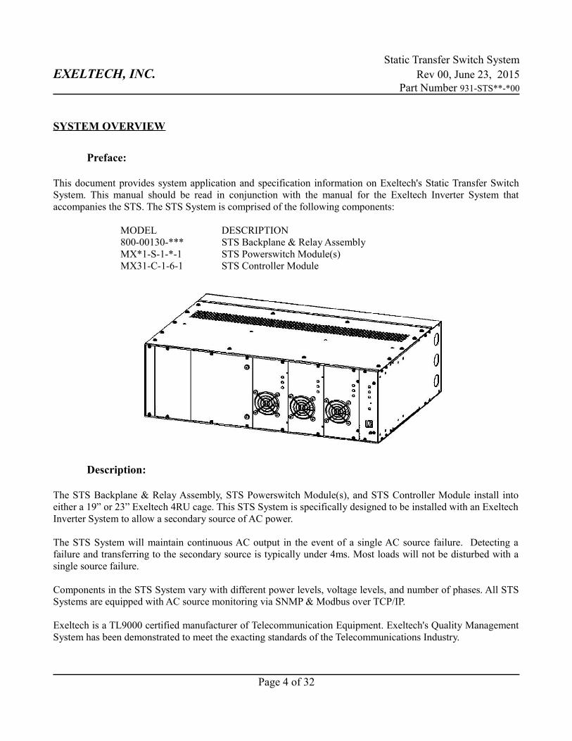
This document provides system application and specification information on Exeltech's Static Transfer SwitchSystem. This manual should be read in conjunction with the manual for the Exeltech Inverter System thataccompanies the STS. The STS System is comprised of the following components:
MODEL DESCRIPTION800-00130-*** STS Backplane & Relay AssemblyMX*1-S-1-*-1 STS Powerswitch Module(s)MX31-C-1-6-1 STS Controller Module
Description:
The STS Backplane & Relay Assembly, STS Powerswitch Module(s), and STS Controller Module install intoeither a 19” or 23” Exeltech 4RU cage. This STS System is specifically designed to be installed with an ExeltechInverter System to allow a secondary source of AC power.
The STS System will maintain continuous AC output in the event of a single AC source failure. Detecting afailure and transferring to the secondary source is typically under 4ms. Most loads will not be disturbed with asingle source failure.
Components in the STS System vary with different power levels, voltage levels, and number of phases. All STSSystems are equipped with AC source monitoring via SNMP & Modbus over TCP/IP.
Exeltech is a TL9000 certified manufacturer of Telecommunication Equipment. Exeltech's Quality ManagementSystem has been demonstrated to meet the exacting standards of the Telecommunications Industry.
Page 4 of 32
Static Transfer Switch SystemEXELTECH, INC. Rev 00, June 23, 2015
Part Number 931-STS**-*00
Page 5 of 32
Static Transfer Switch SystemEXELTECH, INC. Rev 00, June 23, 2015
Part Number 931-STS**-*00
MODULES OVERVIEW
STS Backplane and Relay Assembly
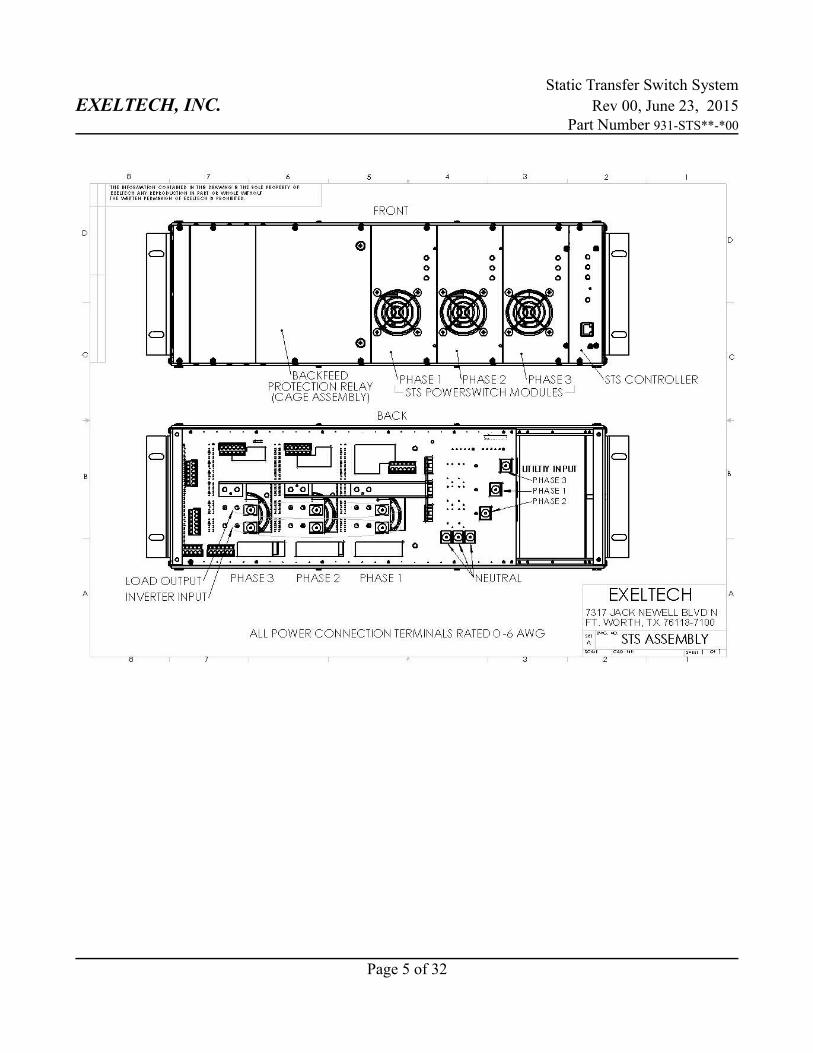
STS Backplane & Relay Assembly is a common component among all STS Systems. The backfeed relay is asafety mechanism to prevent backfeed onto the utility AC source in the event of multiple component failures.The backplane assembly is used to complete power and signal paths between STS Controller, STSPowerswitch(s), and the backfeed relay. The backplane also provides the power output connections, alternatesource input connections, and dry contact alarm connections.
STS Powerswitch Module
The STS Powerswitch module contains the SCR and cooling components required to continuously supply highcurrent to the load from either source. Each phase requires a dedicated STS Powerswitch. So a 3 Phase systemwould require 3 STS Powerswitch modules. The STS Powerswitch is available in 85A and 170A models fordifferent power needs. Each installation will require external overcurrent protection to ensure the STSPowerswitch does not operate above the rated current. Each STS Powerswitch contains LED indicators showingthe status of Inverter Source, Utility Source, and Output. The STS Controller is responsible for operation of theSCR components in the STS Powerswitch.
STS Controller Module
The STS Controller module is a microprocessor based PCB that monitors the AC sources and controls theoperation and automatic transfer of the SCR Powerswitch modules. A toggle switch on the STS Controller isused to set the primary source for the output power. The STS Controller determines the state of each source asgood, bad, or failed and will automatically switch from a bad or failed source to a good source. Total detect andtransfer time for a failed source is typically 4ms.
The STS Controller has three LEDs to indicate the status of each phase and one to indicate the overall status ofthe STS System. LED indicator descriptions can be found in the Module Details section of this manual. All ofthe system information can be accessed through the Ethernet port on the STS Controller. The information isavailable via SNMP & Modbus.
Page 6 of 32
Static Transfer Switch SystemEXELTECH, INC. Rev 00, June 23, 2015
Part Number 931-STS**-*00
OVERVIEW OF SPECIFICATIONS
Input Voltage 90 to 135 Volts AC
Input Frequency Utility: 58 to 61 HzInverter: 54 to 66 Hz
Backfeed Protection Backfeed relay included
Output Voltage Same as utility input voltage or inverter voltage
Output Capacity (per phase)STS Powerswitch 10kW 85 Amps at 117 Volts, 10kW (maximum) @ 40CSTS Powerswitch 20kW 170 Amps at 117 Volts, 20kW (maximum) @ 40C
Transfer Time 4ms typical (Total detect and transfer)
Agency Approval UL 1778, CSA 107.1, CSA 107.3
Framework Type Exeltech 4RU Cage
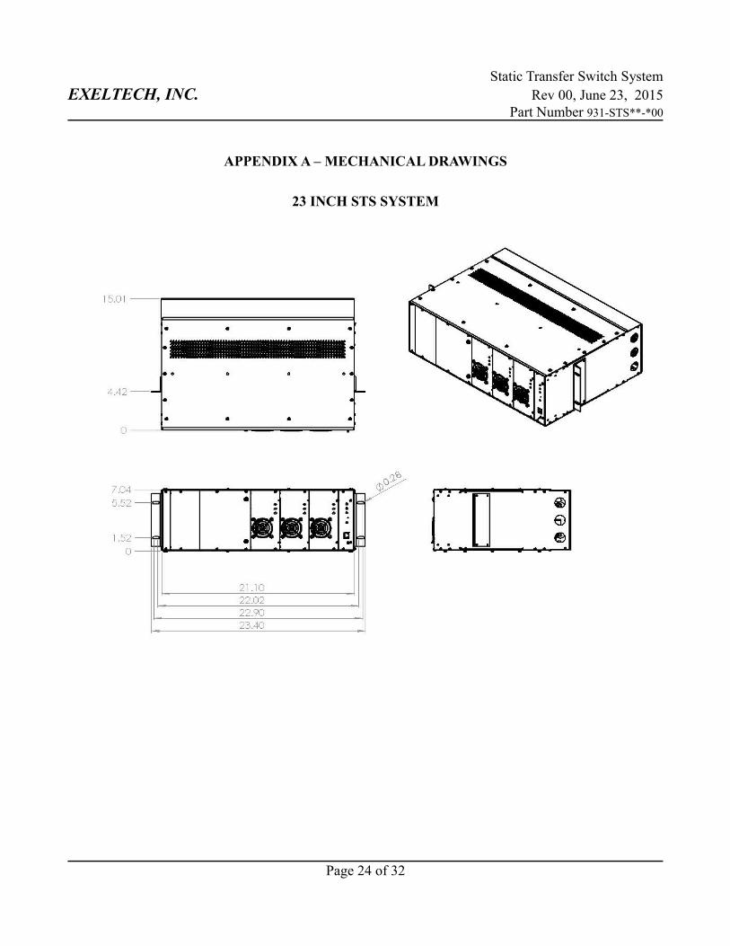
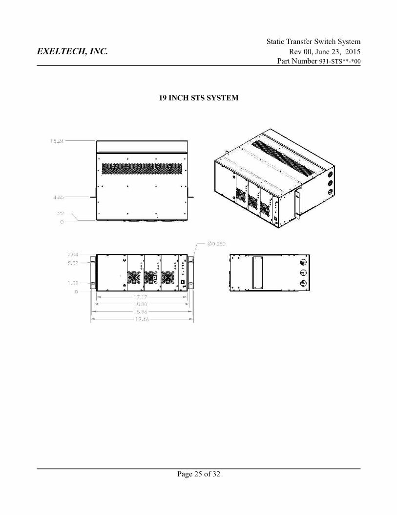
Mounting Width 19 or 23 Inch (Relay Rack Mounting)
Mounting Depth 15 Inches
Mounting Height 7 Inches (4U)
Access Rear for Installation and MaintenanceFront for Operation
Control Microprocessor
Color Black Text LC 20008 Powder Coat
Options Maintenance Bypass Switch (Recommended)
Environment Protected environment -25C to 40C
Page 7 of 32
Static Transfer Switch SystemEXELTECH, INC. Rev 00, June 23, 2015
Part Number 931-STS**-*00
DETAILED DESCRIPTION AND SPECIFICATIONS:
Page 8 of 32
Static Transfer Switch SystemEXELTECH, INC. Rev 00, June 23, 2015
Part Number 931-STS**-*00
STATIC TRANSFER SWITCH SYSTEM
Detailed Description:
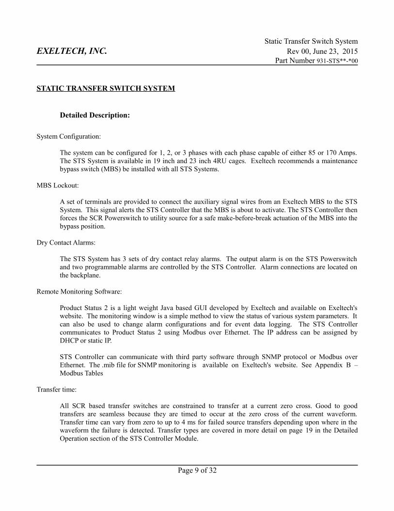
System Configuration:
The system can be configured for 1, 2, or 3 phases with each phase capable of either 85 or 170 Amps.The STS System is available in 19 inch and 23 inch 4RU cages. Exeltech recommends a maintenancebypass switch (MBS) be installed with all STS Systems.
MBS Lockout:
A set of terminals are provided to connect the auxiliary signal wires from an Exeltech MBS to the STSSystem. This signal alerts the STS Controller that the MBS is about to activate. The STS Controller thenforces the SCR Powerswitch to utility source for a safe make-before-break actuation of the MBS into thebypass position.
Dry Contact Alarms:
The STS System has 3 sets of dry contact relay alarms. The output alarm is on the STS Powerswitchand two programmable alarms are controlled by the STS Controller. Alarm connections are located onthe backplane.
Remote Monitoring Software:
Product Status 2 is a light weight Java based GUI developed by Exeltech and available on Exeltech'swebsite. The monitoring window is a simple method to view the status of various system parameters. Itcan also be used to change alarm configurations and for event data logging. The STS Controllercommunicates to Product Status 2 using Modbus over Ethernet. The IP address can be assigned byDHCP or static IP.
STS Controller can communicate with third party software through SNMP protocol or Modbus overEthernet. The .mib file for SNMP monitoring is available on Exeltech's website. See Appendix B –Modbus Tables
Transfer time:
All SCR based transfer switches are constrained to transfer at a current zero cross. Good to goodtransfers are seamless because they are timed to occur at the zero cross of the current waveform.Transfer time can vary from zero to up to 4 ms for failed source transfers depending upon where in thewaveform the failure is detected. Transfer types are covered in more detail on page 19 in the DetailedOperation section of the STS Controller Module.
Page 9 of 32
Static Transfer Switch SystemEXELTECH, INC. Rev 00, June 23, 2015
Part Number 931-STS**-*00
Physical Specifications:
Operating Environment:Temperature: -25C to 40CTemperature derating: 20% of full power for every 10C over 40CHumidity: 5% to 95% non-condensingAltitude: -60m to 1800m (-197 ft. to 5906 ft.)
Dimensions: 7” x 17.2” x 15” (H x W x D) 7” x 21.2” x 15” (H x W x D)
Weight: 85 Amp 170 Amp1 Phase 20.5 lbs 22.5 lbs2 Phase 23 lbs 27 lbs3 Phase 25.5 lbs 31.5 lbs
Finish: Powder Coat – Sherwin Williams Black Text LC 20008
Mounting Clearance Requirements:Above: 1.75” (1 U)Front: 12”Rear: 18”
AC Connection points:Mechanical Lugs: 1/0 – 6 awgRecommended Torque: 45 in-lbs.Customer Interface: 250MCM available in systems with AC customer interface
Page 10 of 32
Static Transfer Switch SystemEXELTECH, INC. Rev 00, June 23, 2015
Part Number 931-STS**-*00
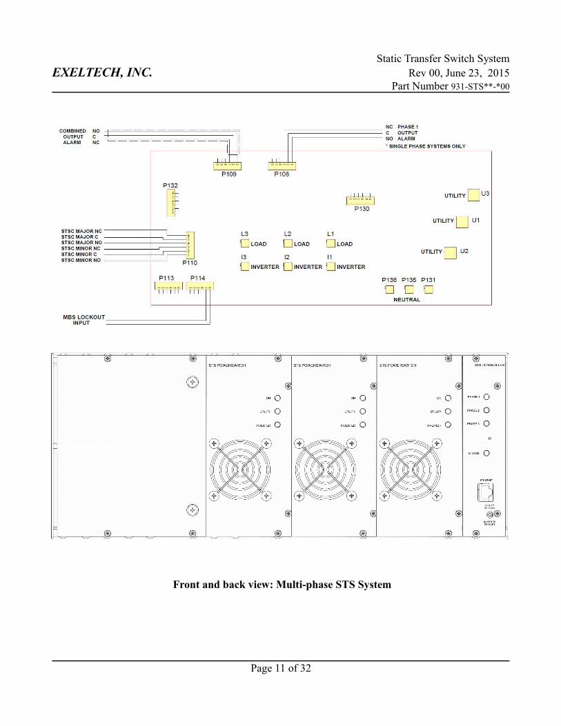
Front and back view: Multi-phase STS System
Page 11 of 32
Static Transfer Switch SystemEXELTECH, INC. Rev 00, June 23, 2015
Part Number 931-STS**-*00
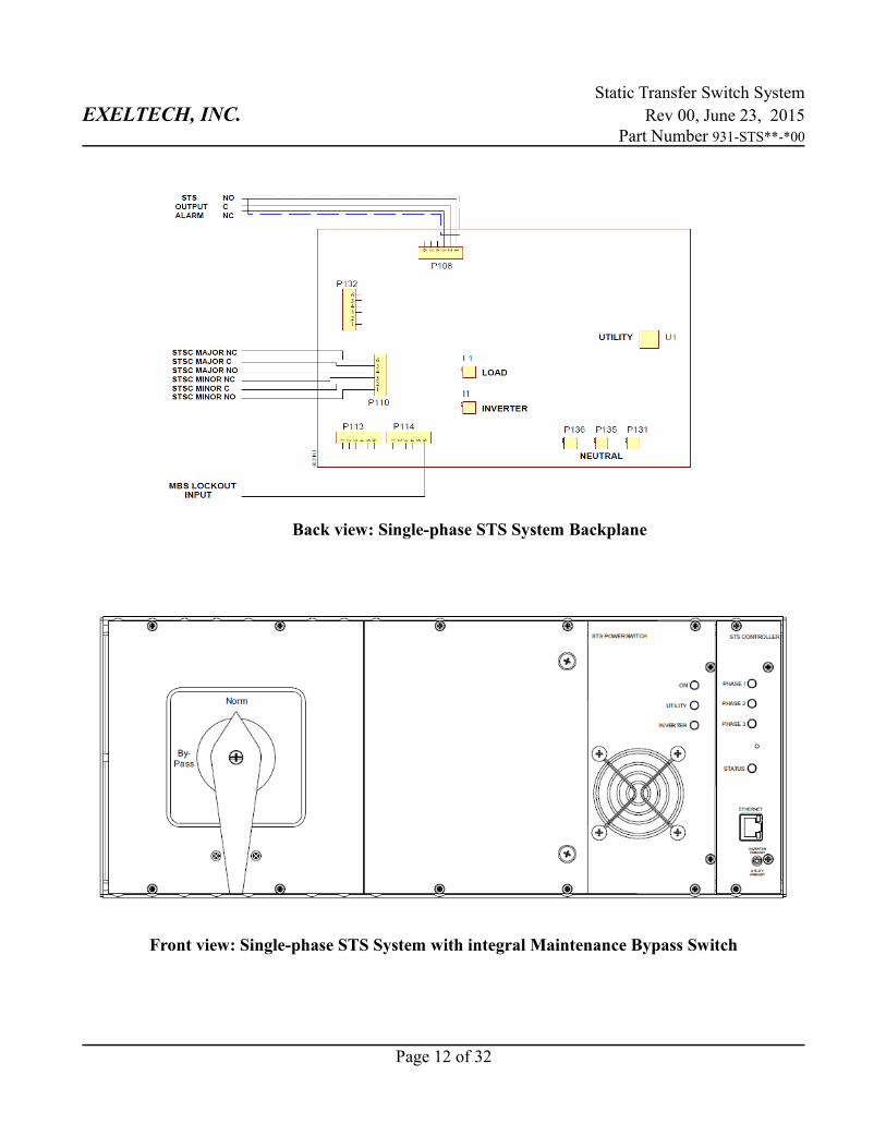
Back view: Single-phase STS System Backplane
Front view: Single-phase STS System with integral Maintenance Bypass Switch
Page 12 of 32
Static Transfer Switch SystemEXELTECH, INC. Rev 00, June 23, 2015
Part Number 931-STS**-*00
Installation:
LOCATION:
The Static Transfer Switch System should be mounted in a location where only non-conductive pollutionmay occur. For full power capability, the temperature must be within the Operating EnvironmentSpecifications. The unit may be operated at elevated temperatures if the loading is reduced. See PhysicalSpecifications for Operating Environment Specifications.
Air is drawn into the Static Transfer Switch System through the front panel mounted fans, and exitsthrough vent holes in the top and rear. Adequate clearance is required in the front, rear, and top for bothcooling and to provide access space for maintenance. See Physical Specifications, Mounting ClearanceRequirements, for details.
AC WIRING:
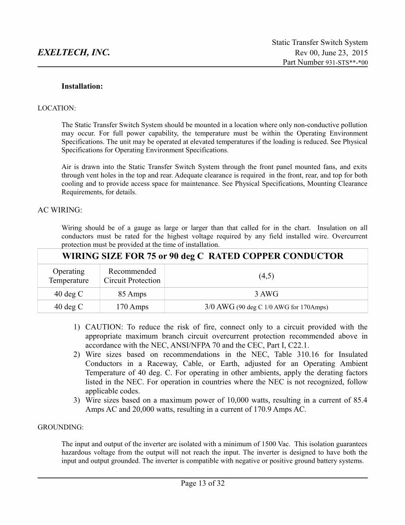
Wiring should be of a gauge as large or larger than that called for in the chart. Insulation on allconductors must be rated for the highest voltage required by any field installed wire. Overcurrentprotection must be provided at the time of installation.
WIRING SIZE FOR 75 or 90 deg C RATED COPPER CONDUCTOR
OperatingTemperature
RecommendedCircuit Protection
(4,5)
40 deg C 85 Amps 3 AWG
40 deg C 170 Amps 3/0 AWG (90 deg C 1/0 AWG for 170Amps)
1) CAUTION: To reduce the risk of fire, connect only to a circuit provided with theappropriate maximum branch circuit overcurrent protection recommended above inaccordance with the NEC, ANSI/NFPA 70 and the CEC, Part I, C22.1.
2) Wire sizes based on recommendations in the NEC, Table 310.16 for InsulatedConductors in a Raceway, Cable, or Earth, adjusted for an Operating AmbientTemperature of 40 deg. C. For operating in other ambients, apply the derating factorslisted in the NEC. For operation in countries where the NEC is not recognized, followapplicable codes.
3) Wire sizes based on a maximum power of 10,000 watts, resulting in a current of 85.4Amps AC and 20,000 watts, resulting in a current of 170.9 Amps AC.
GROUNDING:
The input and output of the inverter are isolated with a minimum of 1500 Vac. This isolation guaranteeshazardous voltage from the output will not reach the input. The inverter is designed to have both theinput and output grounded. The inverter is compatible with negative or positive ground battery systems.
Page 13 of 32
Static Transfer Switch SystemEXELTECH, INC. Rev 00, June 23, 2015
Part Number 931-STS**-*00
Operation and Start Up:
STS System is intended to be installed with an Exeltech inverter. See appropriate InverterInstallation and Operation Manual for complete installation instructions. Installation:
STEP 1: Make sure the Inverter System is mounted securely. STEP 2: Check all input circuits that there is no voltage on any connection.STEP 3: Check Inverter input power and signal connections made in the factory.STEP 4: Connect all lines and neutral of the utility circuit to U1, U2, U3, and Neutral.
Warning: Requires correct phase rotation of utility inputSTEP 5: Connect all lines and neutral of the output circuit to L1, L2, L3, and Neutral.STEP 6: Ground the chassis of the STS System to the facility central earth ground.STEP 7: Neutral to chassis jumper should be removed from the STS System if there exists
a neutral to ground connection anywhere else in the installation. This connection often already exists in the electrical panel for the utility source connection.
STEP 8: Torque all power wire connections. 45in-lb at terminals on STS backplane or 200in-lb at terminals in the customer interface cage.
STEP 9: Connect relay alarm for major and minor STS Controller alarms at P110.Wire size: 12-26awg Torque: 4in-lb
STEP 10: Connect relay alarm for STS Powerswitch output alarm. Single phase: use P108 pins 4-6 Multi-phase: use combined output alarm P109 pins 4-6Wire size: 12-26awg Torque: 4in-lb
STEP 11: If MBS is remotely mounted, connect MBS lockout signal wires from the MBS to P114Pins 5,6. Wire size: 12-26awg Torque: 4in-lb
STEP 12: Double check that all connections are correct and match the installation instructions.
Start Up:
STEP 1: With the MBS set to Bypass, energize the utility source.STEP 2: Verify that voltage is available at the output for the loads.STEP 3: Turn on the inverter source.STEP 4: Verify that the inverter voltage powers up the STS System, that no Output LEDs are on
and the phase indicators are blinking green. This indicates MBS active. Verify all inverter LEDs are green. See Inverter manual for more information on inverter LED's.
STEP 5: Move MBS from Bypass to “pause 1 sec” and listen for the backfeed relay to close.After pausing for at least 1 second, move the MBS to the Normal position.
STEP 6: As MBS is moved to normal, the STS Powerswitch output LED should show green.STEP 7: After 30 seconds, verify the phase indicator LEDs are solid green.STEP 8: STS Controller status LED will blink orange until communication is established for
remote monitoring. See STS Controller section for more information.
Page 14 of 32

Static Transfer Switch SystemEXELTECH, INC. Rev 00, June 23, 2015
Part Number 931-STS**-*00
Maintenance:
See the MX Series manual for total system maintenance procedures.
Page 15 of 32
Static Transfer Switch SystemEXELTECH, INC. Rev 00, June 23, 2015
Part Number 931-STS**-*00
SCR POWERSWITCH MODULE
Detailed Description:
Components:
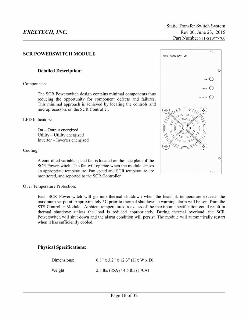
The SCR Powerswitch design contains minimal components thusreducing the opportunity for component defects and failures.This minimal approach is achieved by locating the controls andmicroprocessors on the SCR Controller.
LED Indicators:
On – Output energizedUtility – Utility energizedInverter – Inverter energized
Cooling:
A controlled variable speed fan is located on the face plate of theSCR Powerswitch. The fan will operate when the module sensesan appropriate temperature. Fan speed and SCR temperature aremonitored, and reported to the SCR Controller.
Over Temperature Protection:
Each SCR Powerswitch will go into thermal shutdown when the heatsink temperature exceeds themaximum set point. Approximately 5C prior to thermal shutdown, a warning alarm will be sent from theSTS Controller Module, Ambient temperatures in excess of the maximum specification could result inthermal shutdown unless the load is reduced appropriately. During thermal overload, the SCRPowerswitch will shut down and the alarm condition will persist. The module will automatically restartwhen it has sufficiently cooled.
Physical Specifications:
Dimensions: 6.8” x 3.2” x 12.3” (H x W x D)
Weight: 2.5 lbs (85A) / 4.5 lbs (170A)
Page 16 of 32

Static Transfer Switch SystemEXELTECH, INC. Rev 00, June 23, 2015
Part Number 931-STS**-*00
Electrical Specifications:
SCR Voltage Drop: 1.3V typicalFan Turn On: 45C heatsink temperature (50C for 85A)Fan Full Speed: 60C heatsink temperature (65C for 85A)Thermal Shutdown: 70C heatsink temperature (75C for 85A)Thermal Recovery: 65C heatsink temperature (70C for 85A)Continuous Current Rating 85 Amps, 170 AmpsForm C Relay Alarm 250VAC/VDC 1.5AEfficiency, Heat Dissipation: See Table Below:
Page 17 of 32
Efficiency (%)
170 Amp50 5850 1.3 65.0 5915 98.90 222100 11700 1.3 130.0 11830 98.90 444150 17550 1.3 195.0 17745 98.90 666170 19890 1.3 221.0 20111 98.90 755
85 Amp25 2925 1.3 32.5 2958 98.90 11150 5850 1.3 65.0 5915 98.90 22275 8775 1.3 97.5 8873 98.90 33385 9945 1.3 110.5 10056 98.90 377
Output Current Amps
AC
Output Power @ 117 VAC
V drop Across SCR
Power Loss Watts
Input Power Watts AC
Heat Dissipation
BTU/Hr
Static Transfer Switch SystemEXELTECH, INC. Rev 00, June 23, 2015
Part Number 931-STS**-*00
STS CONTROLLER MODULE
Detailed Description:
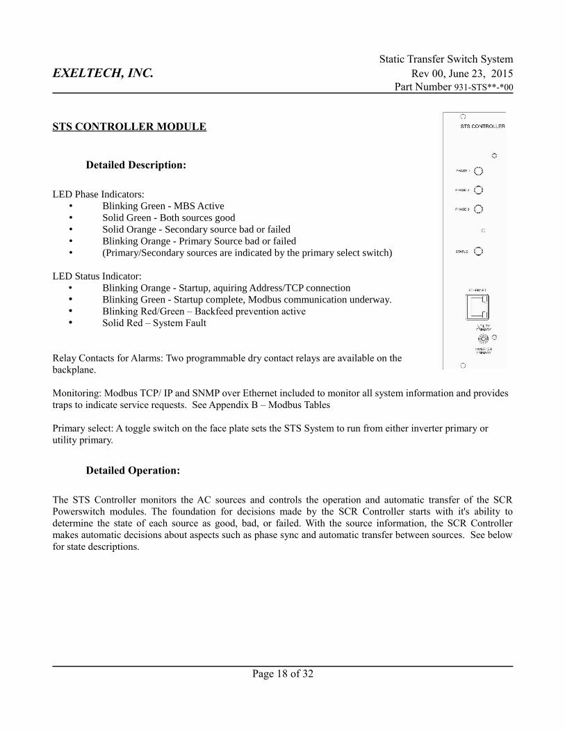
LED Phase Indicators:
• Blinking Green - MBS Active• Solid Green - Both sources good• Solid Orange - Secondary source bad or failed• Blinking Orange - Primary Source bad or failed• (Primary/Secondary sources are indicated by the primary select switch)
LED Status Indicator:• Blinking Orange - Startup, aquiring Address/TCP connection• Blinking Green - Startup complete, Modbus communication underway.• Blinking Red/Green – Backfeed prevention active• Solid Red – System Fault
Relay Contacts for Alarms: Two programmable dry contact relays are available on thebackplane.
Monitoring: Modbus TCP/ IP and SNMP over Ethernet included to monitor all system information and provides traps to indicate service requests. See Appendix B – Modbus Tables Primary select: A toggle switch on the face plate sets the STS System to run from either inverter primary or utility primary.
Detailed Operation:
The STS Controller monitors the AC sources and controls the operation and automatic transfer of the SCRPowerswitch modules. The foundation for decisions made by the SCR Controller starts with it's ability todetermine the state of each source as good, bad, or failed. With the source information, the SCR Controllermakes automatic decisions about aspects such as phase sync and automatic transfer between sources. See belowfor state descriptions.
Page 18 of 32
Static Transfer Switch SystemEXELTECH, INC. Rev 00, June 23, 2015
Part Number 931-STS**-*00
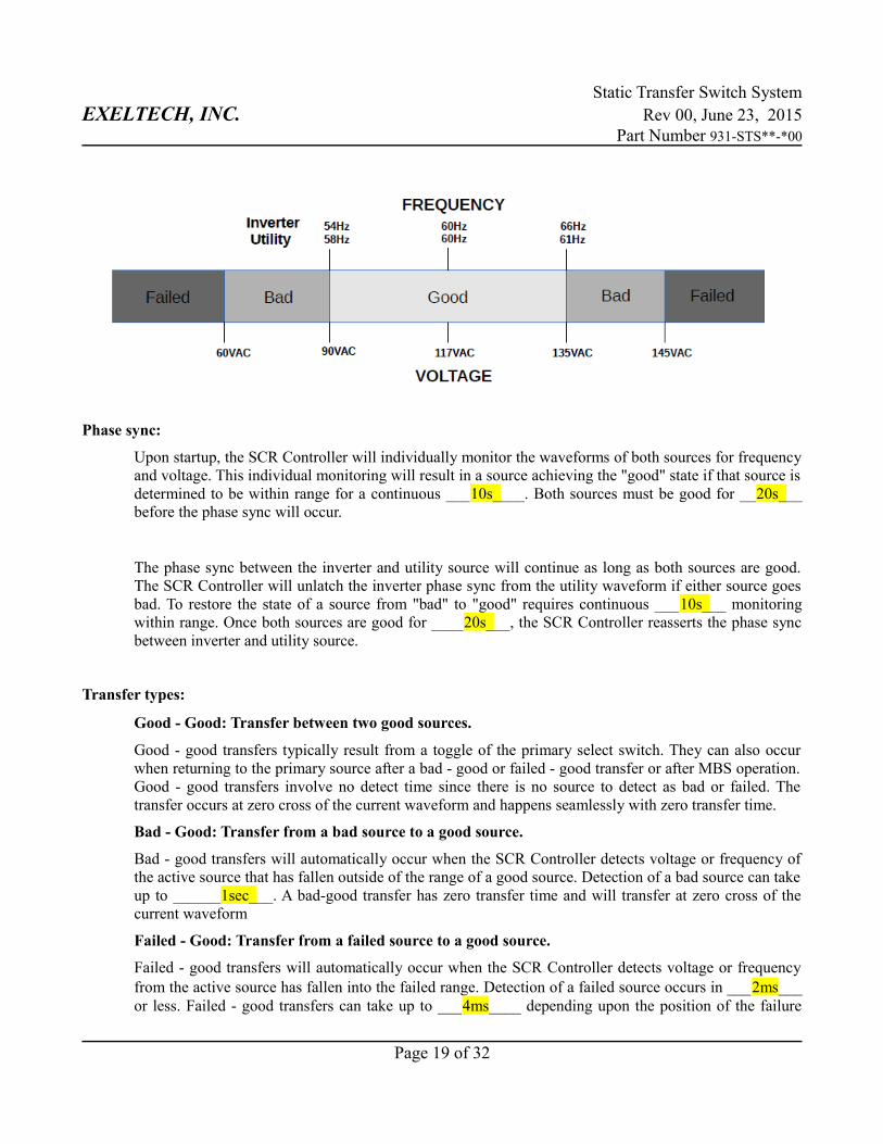
Phase sync:
Upon startup, the SCR Controller will individually monitor the waveforms of both sources for frequencyand voltage. This individual monitoring will result in a source achieving the "good" state if that source isdetermined to be within range for a continuous ___10s____. Both sources must be good for __20s___before the phase sync will occur.
The phase sync between the inverter and utility source will continue as long as both sources are good.The SCR Controller will unlatch the inverter phase sync from the utility waveform if either source goesbad. To restore the state of a source from "bad" to "good" requires continuous ___10s___ monitoringwithin range. Once both sources are good for ____20s___, the SCR Controller reasserts the phase syncbetween inverter and utility source.
Transfer types:
Good - Good: Transfer between two good sources.
Good - good transfers typically result from a toggle of the primary select switch. They can also occurwhen returning to the primary source after a bad - good or failed - good transfer or after MBS operation.Good - good transfers involve no detect time since there is no source to detect as bad or failed. Thetransfer occurs at zero cross of the current waveform and happens seamlessly with zero transfer time.
Bad - Good: Transfer from a bad source to a good source.
Bad - good transfers will automatically occur when the SCR Controller detects voltage or frequency ofthe active source that has fallen outside of the range of a good source. Detection of a bad source can takeup to ______1sec___. A bad-good transfer has zero transfer time and will transfer at zero cross of thecurrent waveform
Failed - Good: Transfer from a failed source to a good source.
Failed - good transfers will automatically occur when the SCR Controller detects voltage or frequencyfrom the active source has fallen into the failed range. Detection of a failed source occurs in ___2ms___or less. Failed - good transfers can take up to ___4ms____ depending upon the position of the failure
Page 19 of 32

Static Transfer Switch SystemEXELTECH, INC. Rev 00, June 23, 2015
Part Number 931-STS**-*00
within the current waveform. Note that all SCR based transfer switches are limited to transfer at currentzero cross.
Bad - Bad: Transfer from one bad source to another bad source.
In the event of two bad sources, the SCR Controller will follow the state of the primary select switch todetermine which source will power the output.
Fail - Bad: Transfer from a failed source to a bad source.
Given a choice of failed source or bad source, the SCR Controller will act in a similar manner to thefailed - good transfer. Detection of the failed source occurs in ____2ms____ or less and automatictransfer from the failed source to the bad source should take ____4ms___ or less.
MBS operation:
Before operation of the MBS switch, Exeltech recommends the STS System be set to utility primary andto confirm the utility source is supplying the power to the loads.
Every Exeltech MBS is equipped with an auxiliary output that provides a signal before the closing ofpower contacts. During MBS operation from Normal to Bypass, the SCR Controller will react to theMBS signal and immediately switch to the utility SCR. Without this signal, the closing of contacts insidethe MBS will act to short the utility source to the output of the inverter which can result in failure ofinverter power modules.
Upon returning the MBS from Bypass to Normal, the SCR Controller will force the output to continue torun from the utility SCR until both sources are good and phase synchronous. This process will take aminimum of ___30s___. Once phase locked, the SCR Controller will follow the primary select switch.
Backfeed Relay:
The backfeed relay is used to prevent backfeed onto the utility source in the event of catastrophic failure.The coil for this normally open relay is powered by the phase 1 utility voltage via a control relay on theSCR Controller. Under normal conditions the SCR controller allows the backfeed relay to closeautomatically when utility is present. When utility is not present the backfeed relay coil cannot beenergized so the relay will open automatically.
The SCR Controller monitors backfeed sensors and will open the backfeed relay under failure scenarioswhere the utility source is still present and the possibility of backfeed exists. The status LED will blinkred/green if the relay is opened for backfeed prevention. The backfeed prevention state will not clearautomatically. See procedure for clearing backfeed prevention state.
Page 20 of 32
Static Transfer Switch SystemEXELTECH, INC. Rev 00, June 23, 2015
Part Number 931-STS**-*00
Clearing backfeed prevention state:
WARNING: Failure to investigate the cause of backfeed before moving the MBS from normal to bypasscan cause major failure of the inverter components.
The safest way to clear backfeed prevention state is shut down the loads and turn off the inverter beforemoving the MBS from normal to bypass. Once in bypass, the system can be diagnosed.
Backfeed prevention state is stored in RAM and can only be cleared by removing all power to the SCRController. The backfeed prevention state will resume upon restart if the possibility for backfeed stillexists.
Thermal Protection:
Primary temperature protection is controlled by the Powerswitch, the STS Controller will also activate toprotect the unit in a severe over temperature condition. At 80C heatsink temperature (85C for 85A) theSTS Controller will open the backfeed relay and activate the utility SCR. This thermal protection statewill automatically clear after the heatsink temperature drops to 65C.
Remote Monitoring:
Remote monitoring is performed via the Ethernet port on the front of the STS Controller.Communication data stream to third party software includes both SNMP protocol and Modbus overEthernet. The .mib file for SNMP monitoring is available on Exeltech's website. The Modbusdefinition tables are found in Appendix B.
Product Status 2 is a light weight Java based GUI developed by Exeltech and available on Exeltech'swebsite. The monitoring window is a simple method to view the status of various system parameters. Itcan also be used to change alarm configurations and for event data logging. The STS Controllercommunicates to Product Status 2 using Modbus over Ethernet. The IP address can be assigned byDHCP or static IP. See Appendix C for information on using Product Status 2.
Page 21 of 32
Static Transfer Switch SystemEXELTECH, INC. Rev 00, June 23, 2015
Part Number 931-STS**-*00
Programmable Alarms:
The STS Controller includes two dry contact relays which can be programed to activate for thefollowing conditions: see Remote Monitoring section
INV Primary – Activates when the primary is NOT set to INV
INV Fail – Activates if the INV source fails
UTIL Fail – Activates when the UTIL source fails (also activates while in maintenance bypass)
MBS – Activates when the MBS is in bypass mode
Phase Sync – Activates when the UTIL source and the INV source are not phase locked (also activates when UTIL is off)
Fan Fail – Activates if a fan failure is detected on the STS Powerswitch
Warm Temp – Activates 5C before going into thermal over temperature protection
Hot Temp – Activates if the STS System is in thermal over temperature protection
Active Source – Activates when either SCR is powering the output
INV Source – Activates when the load is NOT being powered from the INV source
Back Feed Protection – Activates when the SCR Controller is in backfeed prevention mode
Forced INV – Activates when an inverter SCR short has been detected
Forced UTIL – Activates when a utility SCR short has been detected
Forced Contactor – Activates if the STS Controller has forced the backfeed relay open
Contactor – Activates when the backfeed relay is closed
PM Temp* – Activates if a Power Module is over temperature
PM Fail* – Activates if a Power Module fails
CC Fail* – Activates if any phase is running from the secondary control card
Low DC Volts* – Activates if the control card sends a signal because of low DCV
*Indicates programmable alarm only available with Sys Mon II cards.
Additional inverter information and features are available when used with Sys Mon II modules. TheSTS Controller will receive and report information about inverter components. The Sys Mon II modulesoffer additional dry contact alarms that activate for the following conditions:
Minor Alarm - PM Fail, PM Temp, Low DC Volts
Major Alarm - Any time the Sys Mon II determines the inverter source to be bad.
Page 22 of 32
Static Transfer Switch SystemEXELTECH, INC. Rev 00, June 23, 2015
Part Number 931-STS**-*00
Physical Specifications:
Dimensions: 6.8” x 1.6” x 12.3” (H x W x D)
Weight: 0.8 lbs
Electrical Specifications:
Redundant power supplies:Input Voltage: 90 to 135 Volts ACInput Frequency: Utility: 58 to 61 Hz
Inverter: 54 to 66 Hz Form C Relay Alarms: 250VAC/VDC 1.5A
Page 23 of 32
Static Transfer Switch SystemEXELTECH, INC. Rev 00, June 23, 2015
Part Number 931-STS**-*00
APPENDIX A – MECHANICAL DRAWINGS
23 INCH STS SYSTEM
Page 24 of 32
Static Transfer Switch SystemEXELTECH, INC. Rev 00, June 23, 2015
Part Number 931-STS**-*00
19 INCH STS SYSTEM
Page 25 of 32
Static Transfer Switch SystemEXELTECH, INC. Rev 00, June 23, 2015
Part Number 931-STS**-*00
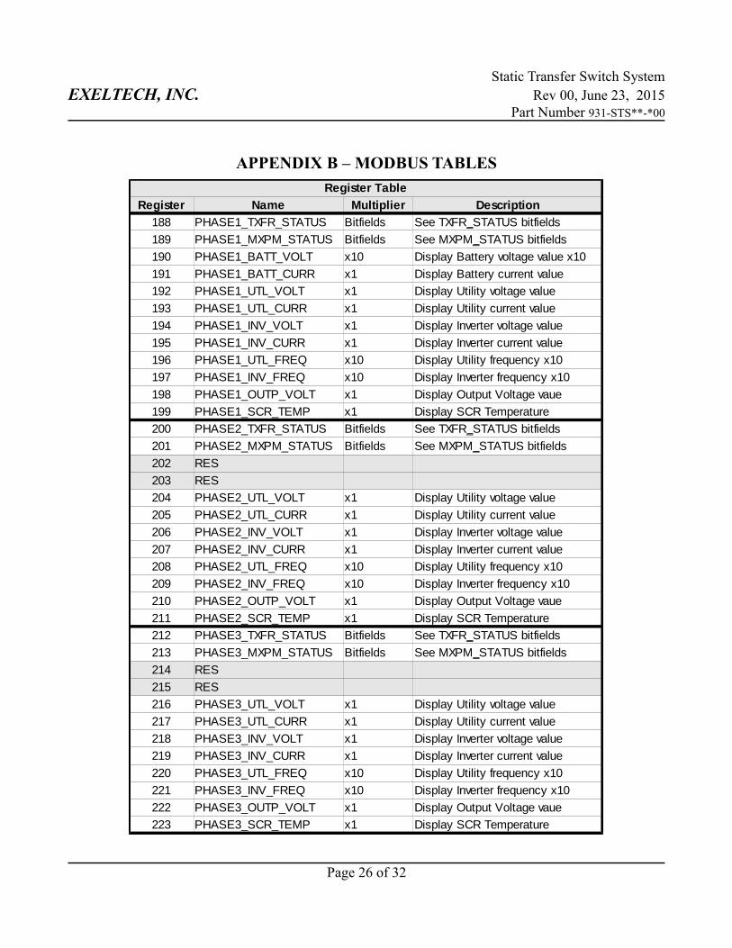
APPENDIX B – MODBUS TABLES
Page 26 of 32
Register Table
Register Name Multiplier Description
188 PHASE1_TXFR_STATUS Bitfields
189 PHASE1_MXPM_STATUS Bitfields
190 PHASE1_BATT_VOLT x10 Display Battery voltage value x10
191 PHASE1_BATT_CURR x1 Display Battery current value
192 PHASE1_UTL_VOLT x1 Display Utility voltage value
193 PHASE1_UTL_CURR x1 Display Utility current value
194 PHASE1_INV_VOLT x1 Display Inverter voltage value
195 PHASE1_INV_CURR x1 Display Inverter current value
196 PHASE1_UTL_FREQ x10 Display Utility frequency x10
197 PHASE1_INV_FREQ x10 Display Inverter frequency x10
198 PHASE1_OUTP_VOLT x1 Display Output Voltage vaue
199 PHASE1_SCR_TEMP x1 Display SCR Temperature
200 PHASE2_TXFR_STATUS Bitfields
201 PHASE2_MXPM_STATUS Bitfields
202 RES
203 RES
204 PHASE2_UTL_VOLT x1 Display Utility voltage value
205 PHASE2_UTL_CURR x1 Display Utility current value
206 PHASE2_INV_VOLT x1 Display Inverter voltage value
207 PHASE2_INV_CURR x1 Display Inverter current value
208 PHASE2_UTL_FREQ x10 Display Utility frequency x10
209 PHASE2_INV_FREQ x10 Display Inverter frequency x10
210 PHASE2_OUTP_VOLT x1 Display Output Voltage vaue
211 PHASE2_SCR_TEMP x1 Display SCR Temperature
212 PHASE3_TXFR_STATUS Bitfields
213 PHASE3_MXPM_STATUS Bitfields
214 RES
215 RES
216 PHASE3_UTL_VOLT x1 Display Utility voltage value
217 PHASE3_UTL_CURR x1 Display Utility current value
218 PHASE3_INV_VOLT x1 Display Inverter voltage value
219 PHASE3_INV_CURR x1 Display Inverter current value
220 PHASE3_UTL_FREQ x10 Display Utility frequency x10
221 PHASE3_INV_FREQ x10 Display Inverter frequency x10
222 PHASE3_OUTP_VOLT x1 Display Output Voltage vaue
223 PHASE3_SCR_TEMP x1 Display SCR Temperature
See TXFR_STATUS bitfields
See MXPM_STATUS bitfields
See TXFR_STATUS bitfields
See MXPM_STATUS bitfields
See TXFR_STATUS bitfields
See MXPM_STATUS bitfields
Static Transfer Switch SystemEXELTECH, INC. Rev 00, June 23, 2015
Part Number 931-STS**-*00
Page 27 of 32
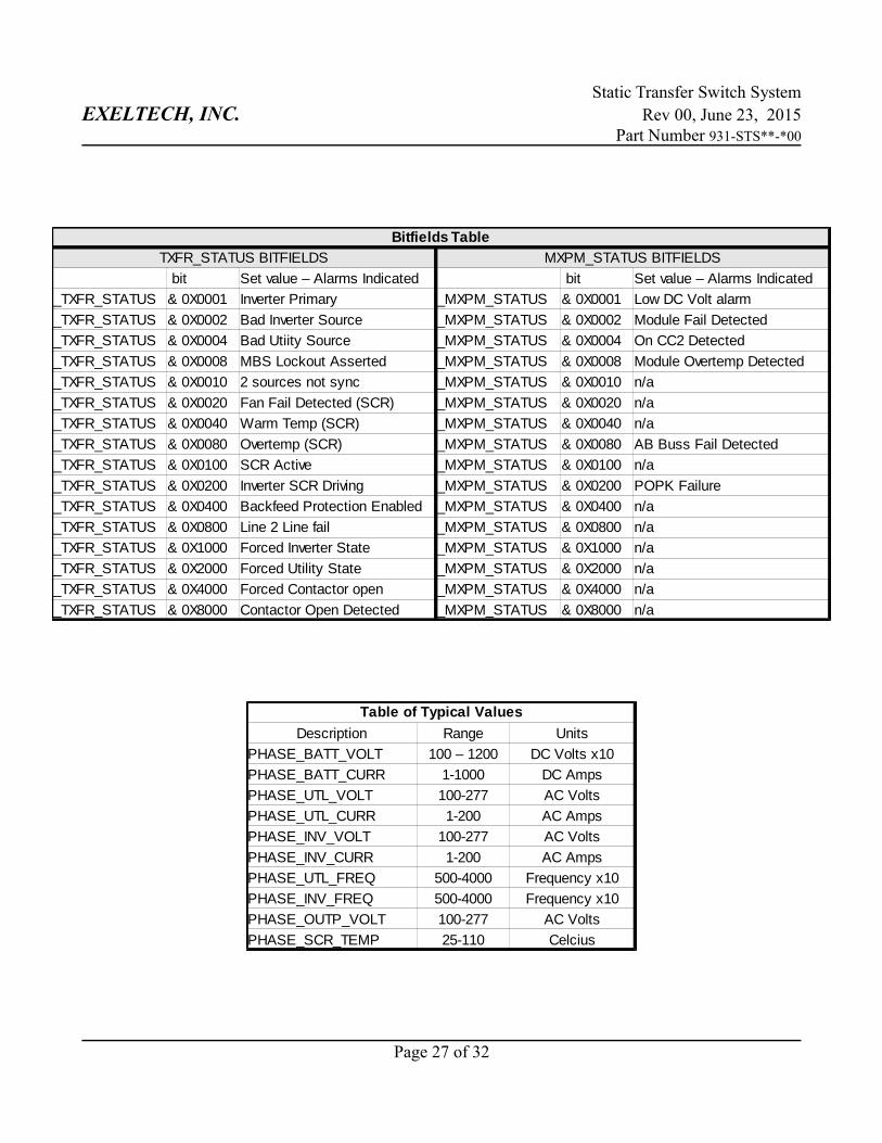
Bitfields Table
TXFR_STATUS BITFIELDS MXPM_STATUS BITFIELDS
bit Set value – Alarms Indicated bit Set value – Alarms Indicated
_TXFR_STATUS & 0X0001 Inverter Primary _MXPM_STATUS & 0X0001 Low DC Volt alarm
_TXFR_STATUS & 0X0002 Bad Inverter Source _MXPM_STATUS & 0X0002 Module Fail Detected
_TXFR_STATUS & 0X0004 Bad Utiity Source _MXPM_STATUS & 0X0004 On CC2 Detected
_TXFR_STATUS & 0X0008 MBS Lockout Asserted _MXPM_STATUS & 0X0008 Module Overtemp Detected
_TXFR_STATUS & 0X0010 2 sources not sync _MXPM_STATUS & 0X0010 n/a
_TXFR_STATUS & 0X0020 Fan Fail Detected (SCR) _MXPM_STATUS & 0X0020 n/a
_TXFR_STATUS & 0X0040 Warm Temp (SCR) _MXPM_STATUS & 0X0040 n/a
_TXFR_STATUS & 0X0080 Overtemp (SCR) _MXPM_STATUS & 0X0080 AB Buss Fail Detected
_TXFR_STATUS & 0X0100 SCR Active _MXPM_STATUS & 0X0100 n/a
_TXFR_STATUS & 0X0200 Inverter SCR Driving _MXPM_STATUS & 0X0200 POPK Failure
_TXFR_STATUS & 0X0400 Backfeed Protection Enabled _MXPM_STATUS & 0X0400 n/a
_TXFR_STATUS & 0X0800 Line 2 Line fail _MXPM_STATUS & 0X0800 n/a
_TXFR_STATUS & 0X1000 Forced Inverter State _MXPM_STATUS & 0X1000 n/a
_TXFR_STATUS & 0X2000 Forced Utility State _MXPM_STATUS & 0X2000 n/a
_TXFR_STATUS & 0X4000 Forced Contactor open _MXPM_STATUS & 0X4000 n/a
_TXFR_STATUS & 0X8000 Contactor Open Detected _MXPM_STATUS & 0X8000 n/a
Table of Typical Values
Description Range Units
PHASE_BATT_VOLT 100 – 1200 DC Volts x10
PHASE_BATT_CURR 1-1000 DC Amps
PHASE_UTL_VOLT 100-277 AC Volts
PHASE_UTL_CURR 1-200 AC Amps
PHASE_INV_VOLT 100-277 AC Volts
PHASE_INV_CURR 1-200 AC Amps
PHASE_UTL_FREQ 500-4000 Frequency x10
PHASE_INV_FREQ 500-4000 Frequency x10
PHASE_OUTP_VOLT 100-277 AC Volts
PHASE_SCR_TEMP 25-110 Celcius
Static Transfer Switch SystemEXELTECH, INC. Rev 00, June 23, 2015
Part Number 931-STS**-*00
APPENDIX C – PRODUCT STATUS 2 OPERATION
Appendix C will cover the operation of Product Status 2 software available on the Exeltech website. This willallow the end user to monitor system parameters, reconfigure the programmable alarms, and view event historydata logs. To communicate to the STS Controller via the Ethernet port your network must be able to assign theinitial IP address via DHCP.
To set the STS Controller to work in Static IP mode, press and hold the reset button for 10 to 12 seconds until thestatus light turns off and stays off. Once the communication port reboots, the default IP address will be(192.168.1.1/255.255.255.0/192.168.1.0). Instructions for changing the static IP address are covered later in thisAppendix.
Setting up Product Status to communicate with your STS Controller:
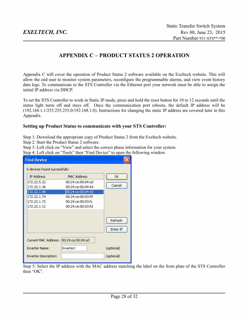
Step 1: Download the appropriate copy of Product Status 2 from the Exeltech website.Step 2: Start the Product Status 2 software.Step 3: Left click on “View” and select the correct phase information for your system.Step 4: Left click on “Tools” then “Find Device” to open the following window.
Step 5: Select the IP address with the MAC address matching the label on the front plate of the STS Controllerthen “OK”.
Page 28 of 32
Static Transfer Switch SystemEXELTECH, INC. Rev 00, June 23, 2015
Part Number 931-STS**-*00
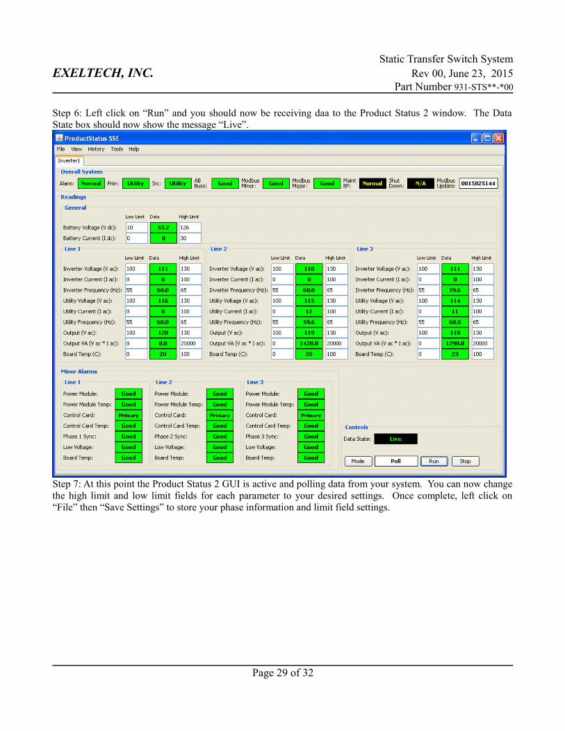
Step 6: Left click on “Run” and you should now be receiving daa to the Product Status 2 window. The DataState box should now show the message “Live”.
Step 7: At this point the Product Status 2 GUI is active and polling data from your system. You can now changethe high limit and low limit fields for each parameter to your desired settings. Once complete, left click on“File” then “Save Settings” to store your phase information and limit field settings.
Page 29 of 32
Static Transfer Switch SystemEXELTECH, INC. Rev 00, June 23, 2015
Part Number 931-STS**-*00
Configuring the programmable alarms your STS Controller:
The STS controller will ship with default alarm settings that will activate the Minor Alarm if the load is notbeing powered from the inverter source. The Major Alarm will activate if either the utility source or the invertersource fail. Follow these instructions to change the programmable alarm configuration.
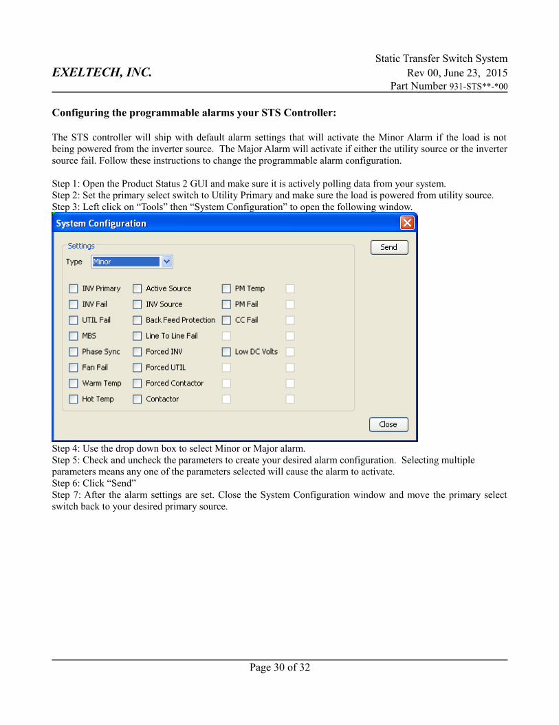
Step 1: Open the Product Status 2 GUI and make sure it is actively polling data from your system.Step 2: Set the primary select switch to Utility Primary and make sure the load is powered from utility source.Step 3: Left click on “Tools” then “System Configuration” to open the following window.
Step 4: Use the drop down box to select Minor or Major alarm. Step 5: Check and uncheck the parameters to create your desired alarm configuration. Selecting multiple parameters means any one of the parameters selected will cause the alarm to activate.Step 6: Click “Send”Step 7: After the alarm settings are set. Close the System Configuration window and move the primary selectswitch back to your desired primary source.
Page 30 of 32
Static Transfer Switch SystemEXELTECH, INC. Rev 00, June 23, 2015
Part Number 931-STS**-*00
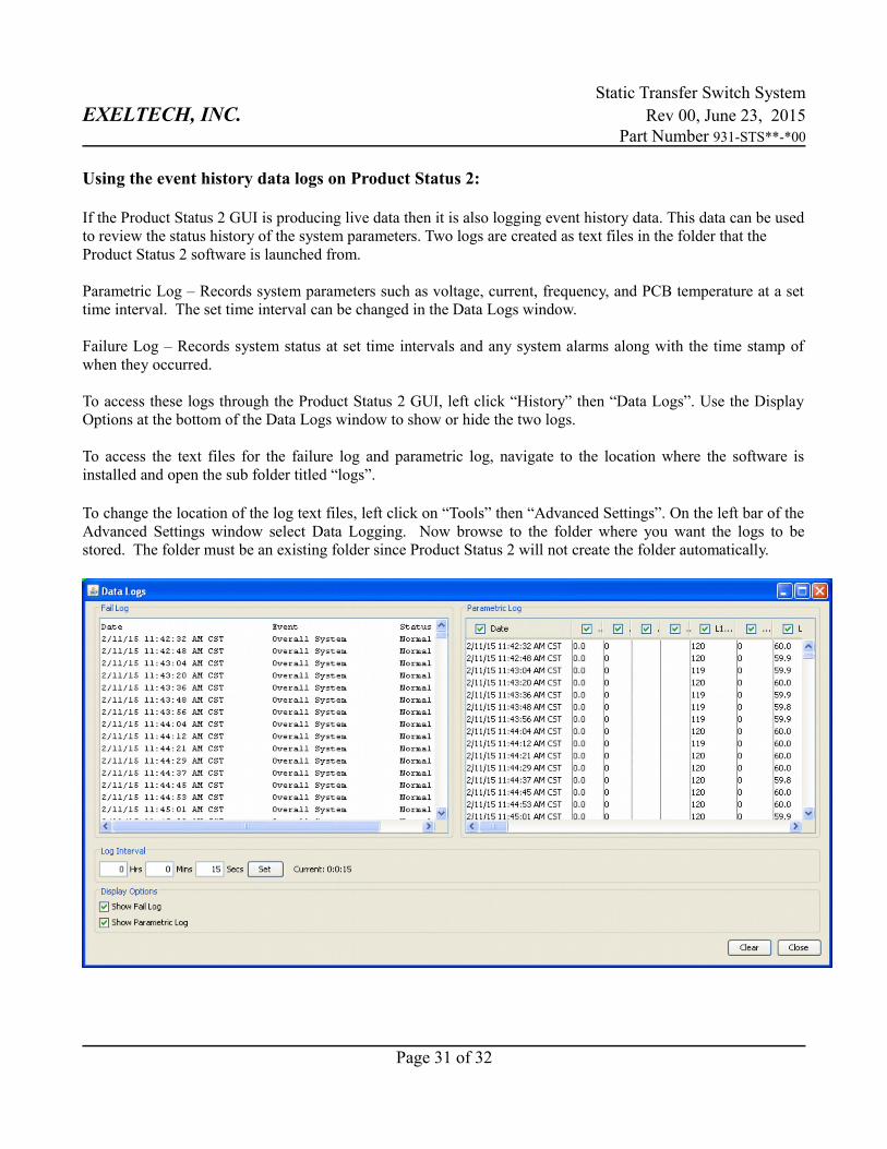
Using the event history data logs on Product Status 2:
If the Product Status 2 GUI is producing live data then it is also logging event history data. This data can be usedto review the status history of the system parameters. Two logs are created as text files in the folder that the Product Status 2 software is launched from.
Parametric Log – Records system parameters such as voltage, current, frequency, and PCB temperature at a settime interval. The set time interval can be changed in the Data Logs window.
Failure Log – Records system status at set time intervals and any system alarms along with the time stamp ofwhen they occurred.
To access these logs through the Product Status 2 GUI, left click “History” then “Data Logs”. Use the DisplayOptions at the bottom of the Data Logs window to show or hide the two logs.
To access the text files for the failure log and parametric log, navigate to the location where the software isinstalled and open the sub folder titled “logs”.
To change the location of the log text files, left click on “Tools” then “Advanced Settings”. On the left bar of theAdvanced Settings window select Data Logging. Now browse to the folder where you want the logs to bestored. The folder must be an existing folder since Product Status 2 will not create the folder automatically.
Page 31 of 32
Static Transfer Switch SystemEXELTECH, INC. Rev 00, June 23, 2015
Part Number 931-STS**-*00
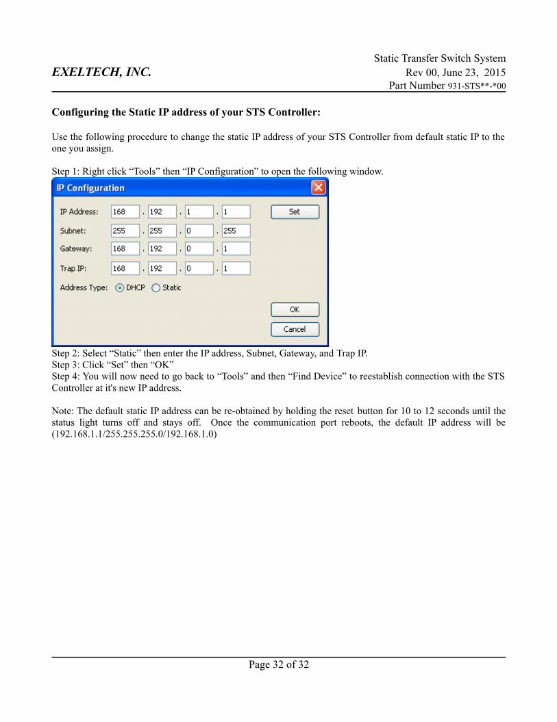
Configuring the Static IP address of your STS Controller:
Use the following procedure to change the static IP address of your STS Controller from default static IP to theone you assign.
Step 1: Right click “Tools” then “IP Configuration” to open the following window.
Step 2: Select “Static” then enter the IP address, Subnet, Gateway, and Trap IP.Step 3: Click “Set” then “OK”Step 4: You will now need to go back to “Tools” and then “Find Device” to reestablish connection with the STSController at it's new IP address.
Note: The default static IP address can be re-obtained by holding the reset button for 10 to 12 seconds until thestatus light turns off and stays off. Once the communication port reboots, the default IP address will be(192.168.1.1/255.255.255.0/192.168.1.0)
Page 32 of 32