structure analysis i - الصفحات الشخصية...
TRANSCRIPT
Structure Analysis IStructure Analysis IChapter 4Chapter 4
Chapter1 Types of Structures & Loads 1
Chapter 4Chapter 4
I t l L diInternal Loading Developed in Structural p
Members
Internal loading at a specified PointInternal loading at a specified Point
In GeneralIn General
• The loading for coplanar structure will consist of a normal force N shear force Vconsist of a normal force N, shear force V, and bending moment M.
Th l di ll h l• These loading actually represent the resultants of the stress distribution acting over the member’s
i lcross-sectional are
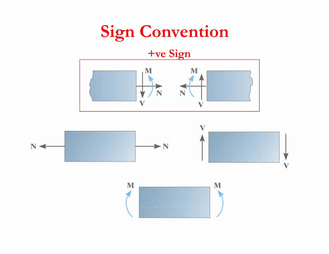
Sign Convention+ve Sign
Procedure for analysisProcedure for analysis
• Support ReactionSupport Reaction• Free-Body Diagram
E i f E ilib i• Equation of Equilibrium
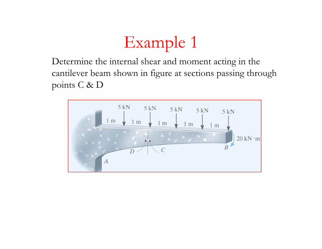
Example 1Example 1Determine the internal shear and moment acting in the cantilever beam shown in figure at sections passing through g p g gpoints C & D
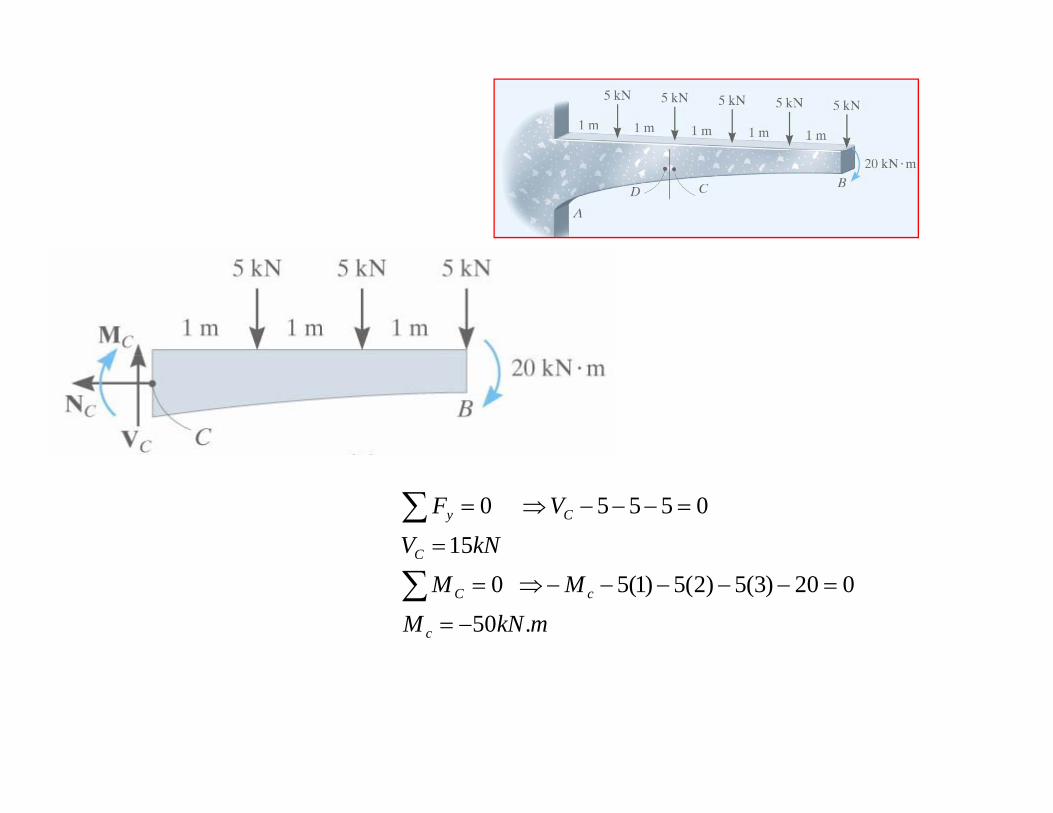
kNV
V F
C
Cy
15
05550
=
=−−−⇒=∑
mkNMMM
c
cC
.50020)3(5)2(5)1(5 0
−=
=−−−−−⇒=∑
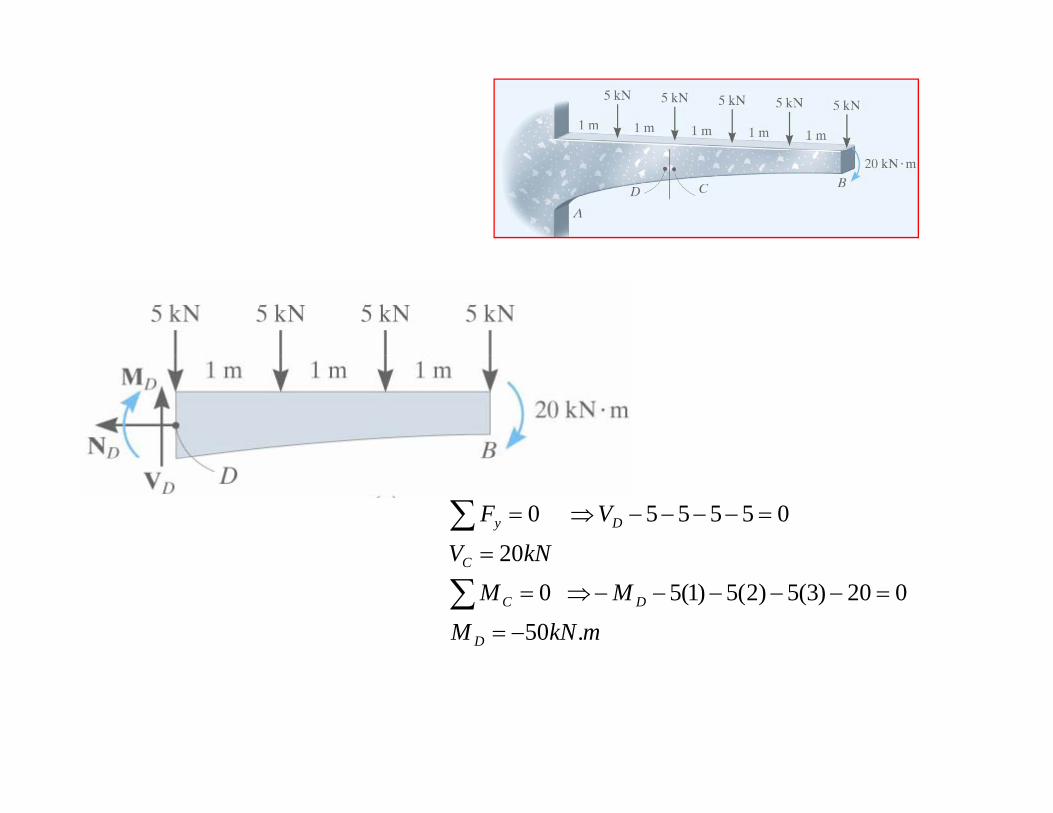
kNV
V F
C
Dy
20
055550
=
=−−−−⇒=∑
mkNMMM
kNV
D
DC
C
.50020)3(5)2(5)1(5 0
20
−=
=−−−−−⇒=∑
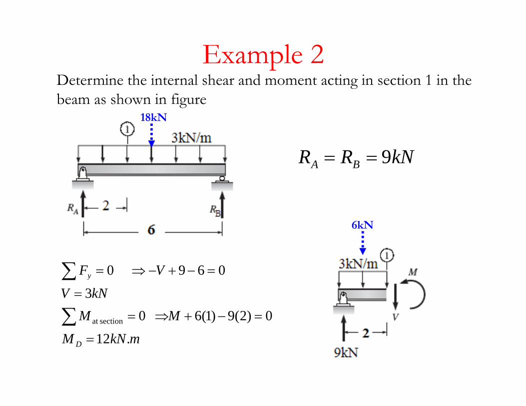
Example 2D i h i l h d i i i 1 i hDetermine the internal shear and moment acting in section 1 in the beam as shown in figure
18kN
kNRR BA 9==
6kN
V Fy 0690 =−+−⇒=∑
MMkNV
y
0)2(9)1(6 03
sectionat =−+⇒=
=
∑
∑
mkNM D .12=
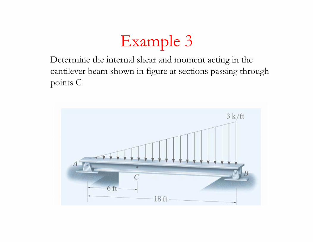
Example 3Example 3Determine the internal shear and moment acting in the cantilever beam shown in figure at sections passing through g p g gpoints C
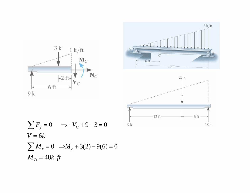
V F Cy 0390 =−+−⇒=∑
ftkMMM
kV
c
480)6(9)2(3 0
6
c
=
=−+⇒=
=
∑ftkM D .48=
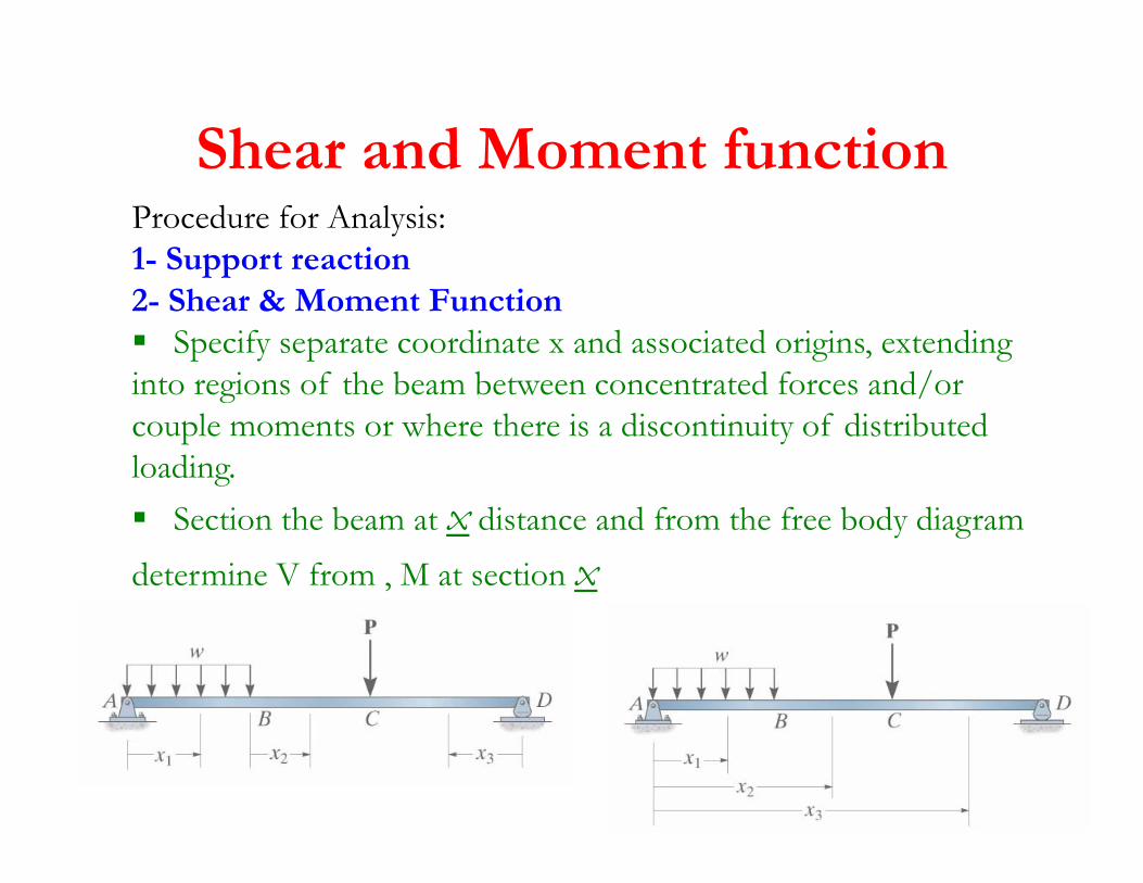
Shear and Moment functionShear and Moment functionProcedure for Analysis:1- Support reactionpp2- Shear & Moment Function
Specify separate coordinate x and associated origins, extending into regions of the beam between concentrated forces and/orinto regions of the beam between concentrated forces and/or couple moments or where there is a discontinuity of distributed loading.
Section the beam at x distance and from the free body diagram determine V from , M at section x
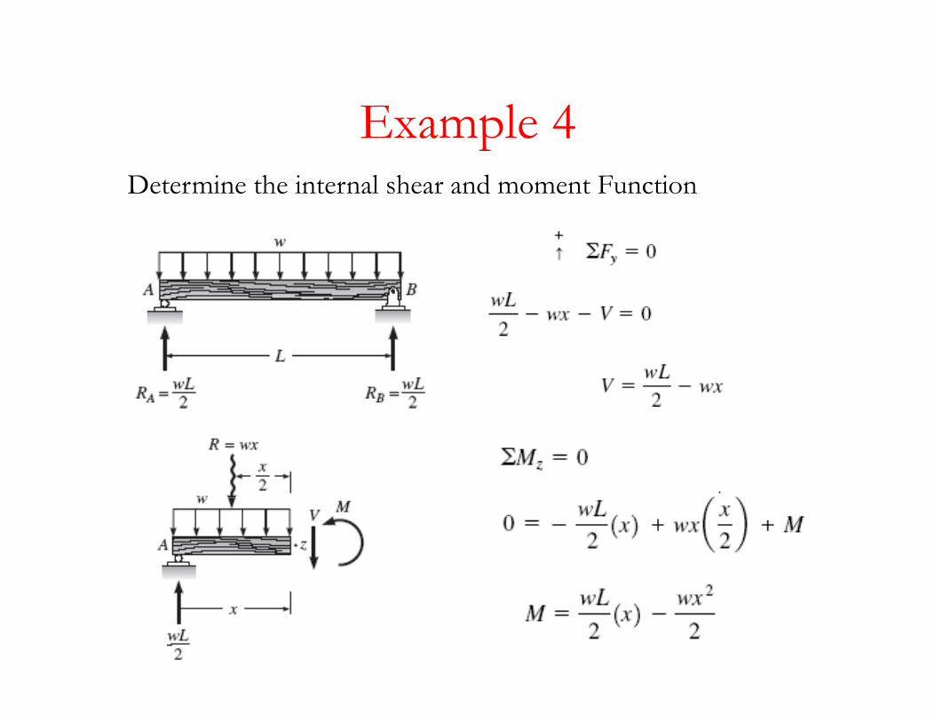
Example 4Example 4Determine the internal shear and moment Function
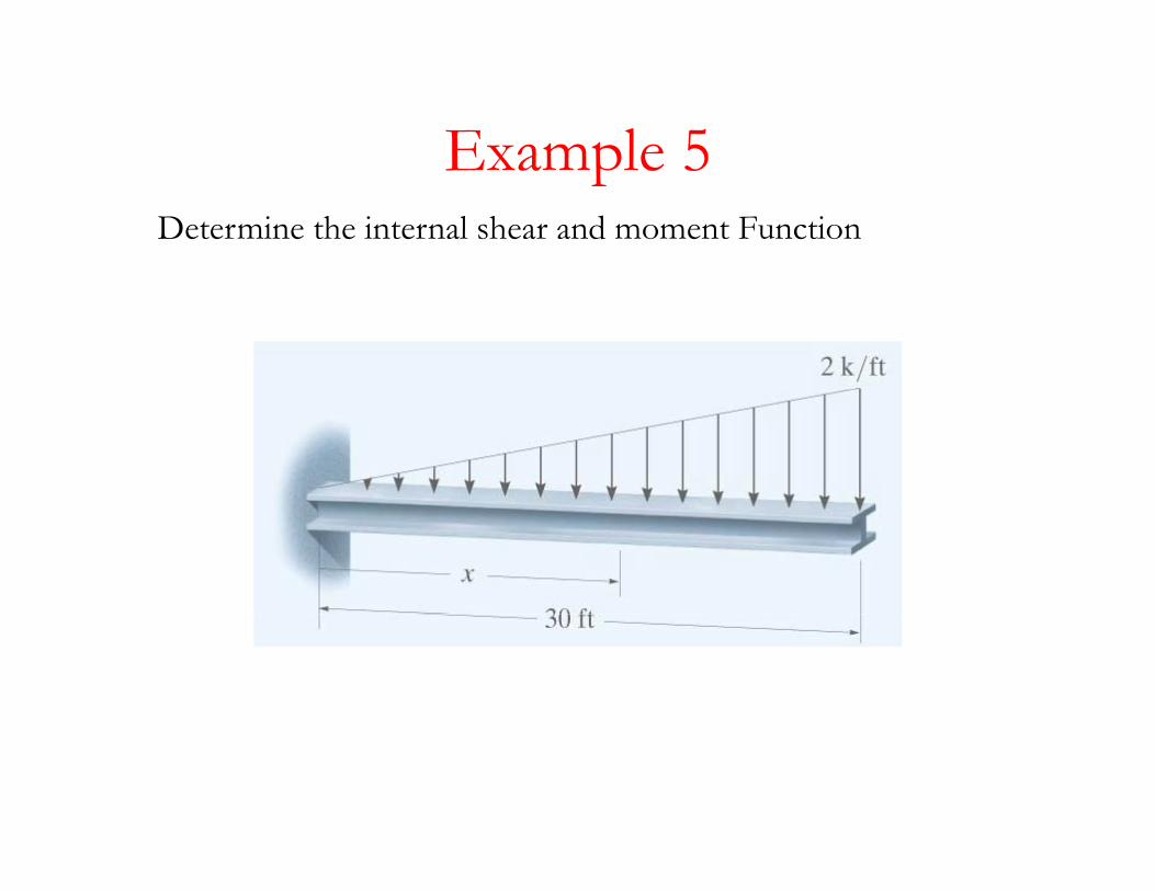
Example 5Example 5Determine the internal shear and moment Function
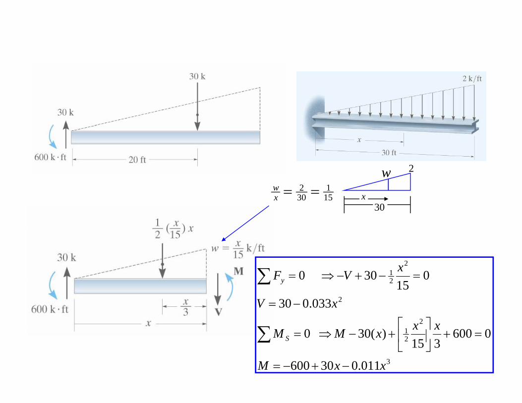
w 2
151
302 ==x
ww
30x
21 0300 xVF =−+−⇒=∑
21
2
2
)(
033.030
015
300
xx
xV
V Fy
⎤⎡
−=
+⇒
∑
∑
3
21
011.030600
0600315
)(30 0
xxM
xxxMM S
−+−=
=+⎥⎦
⎤⎢⎣
⎡+−⇒=∑
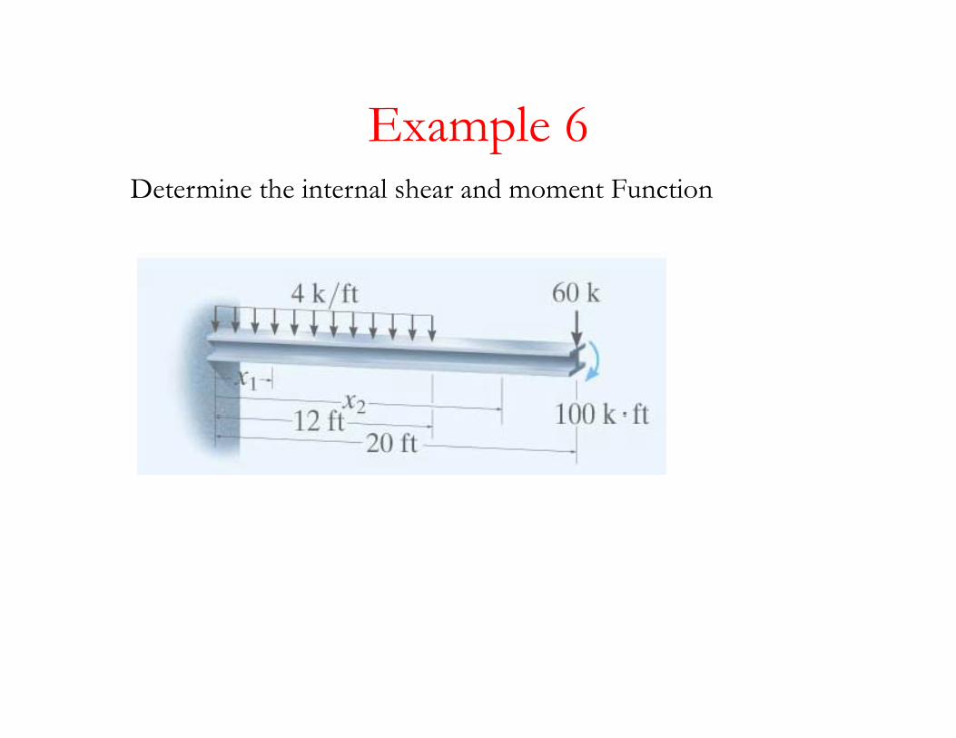
Example 6Example 6Determine the internal shear and moment Function
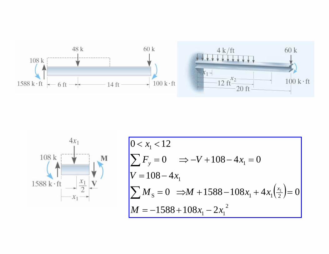
120 x <<
1
1
4108
041080120
xV
xV Fx
y
=
=−+−⇒=
<<
∑
( )2
211S
1
21081588
041081588 0
41081
M
xxMM
xVx =+−+⇒=
−=
∑2
11 21081588 xxM −+−=
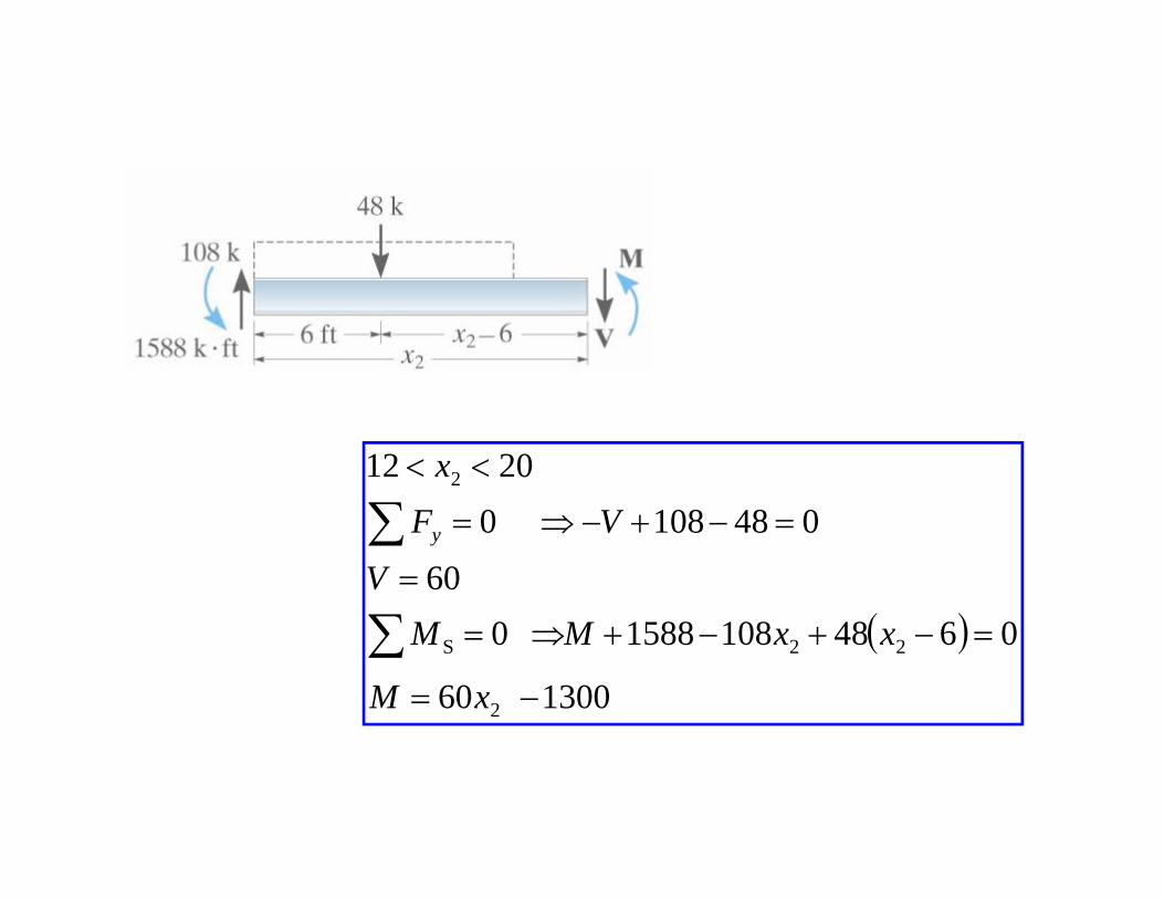
2012 2 <<
∑x
( )60
0481080
=
=−+−⇒=
∑
∑V
V Fy
( )130060
06481081588 0
2
22S
−=
=−+−+⇒=∑xM
xxMM
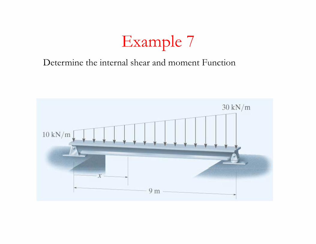
Example 7Example 7Determine the internal shear and moment Function
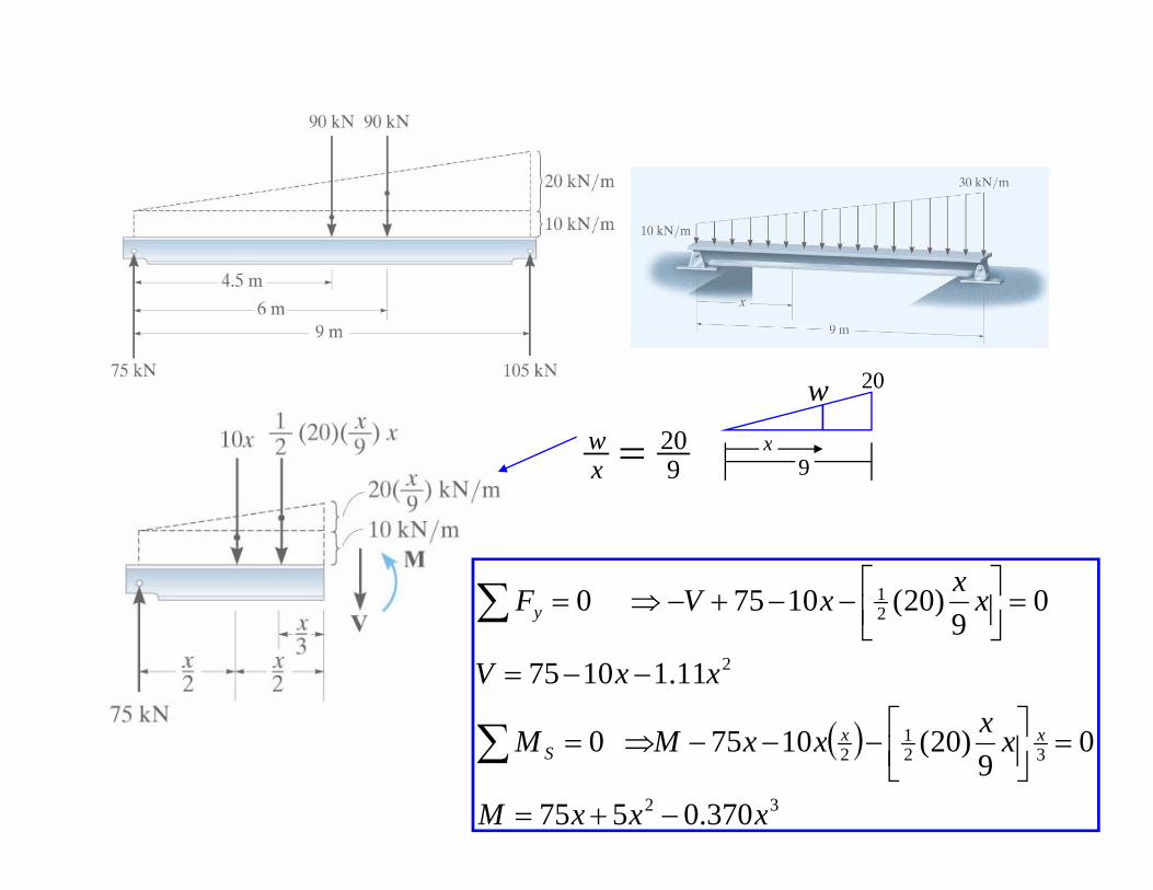
w 20
920=x
w
w
9x
21 0)20(10750 xxxV Fy =⎥⎦
⎤⎢⎣⎡−−+−⇒=∑
( )
2
2
11.110759
)(
xxxV
y
⎤⎡
−−=
⎥⎦⎢⎣
∑
∑
( )32
321
2
370.0575
09
)20(1075 0
xxxM
xxxxMM xxS
−+=
=⎥⎦⎤
⎢⎣⎡−−−⇒=∑
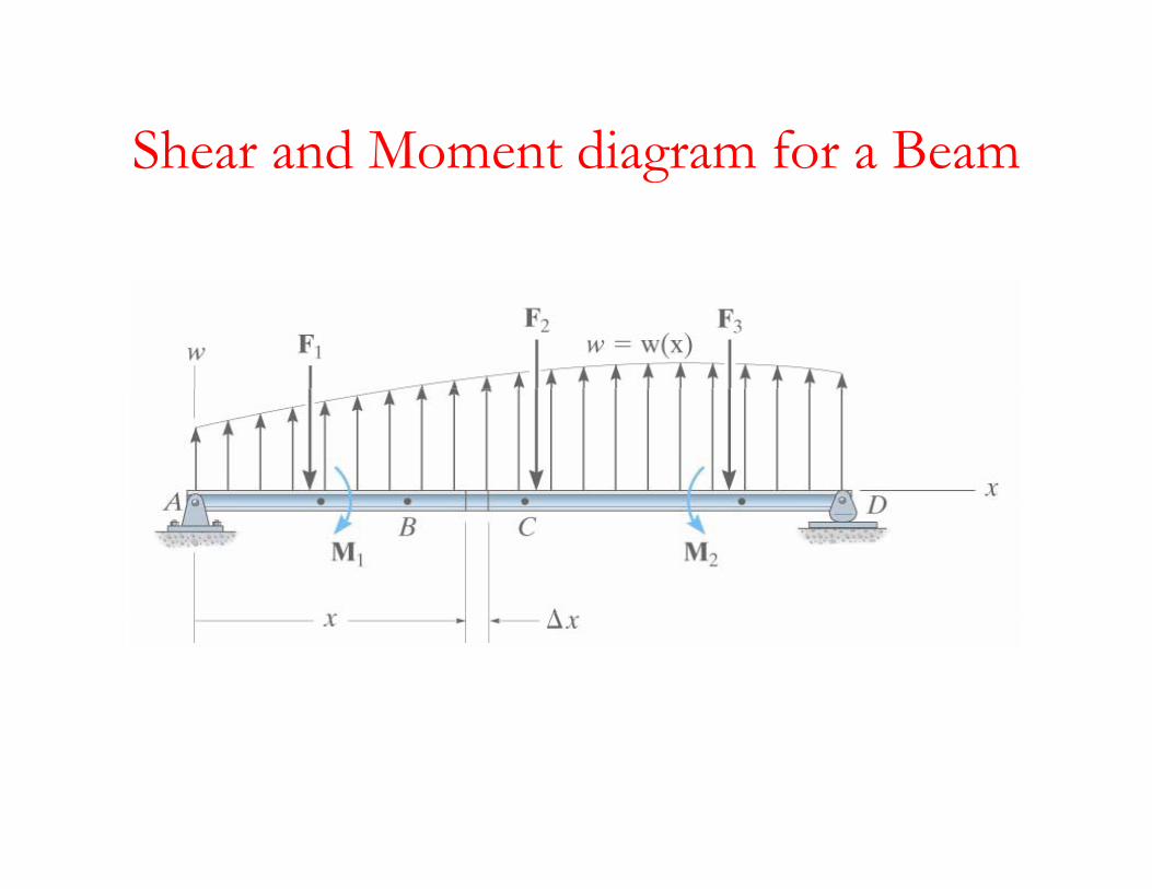
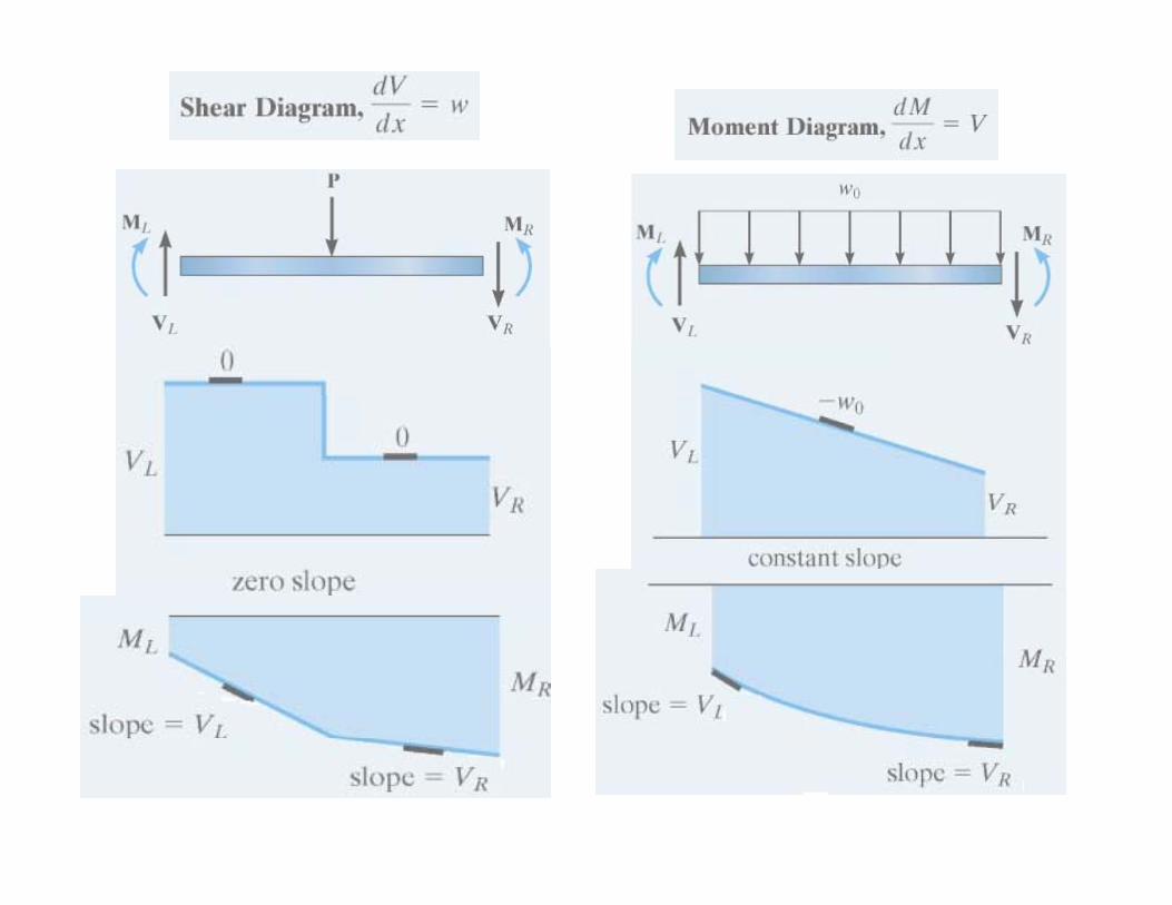
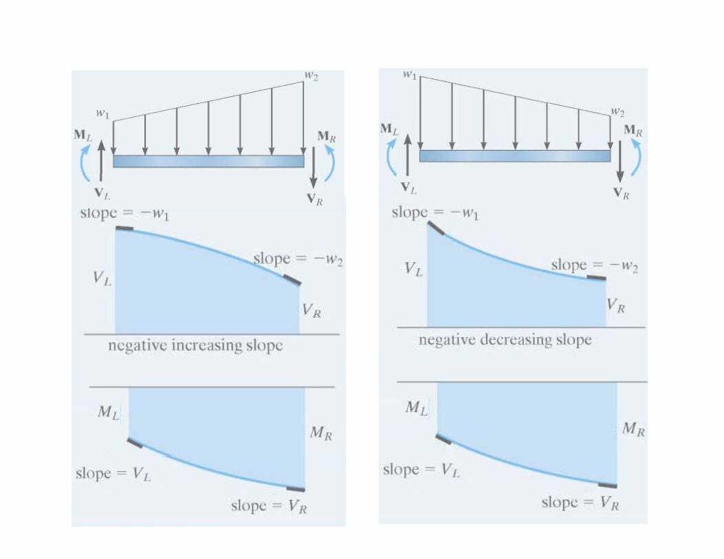
Shear and Moment diagram for a BeamShear and Moment diagram for a Beam
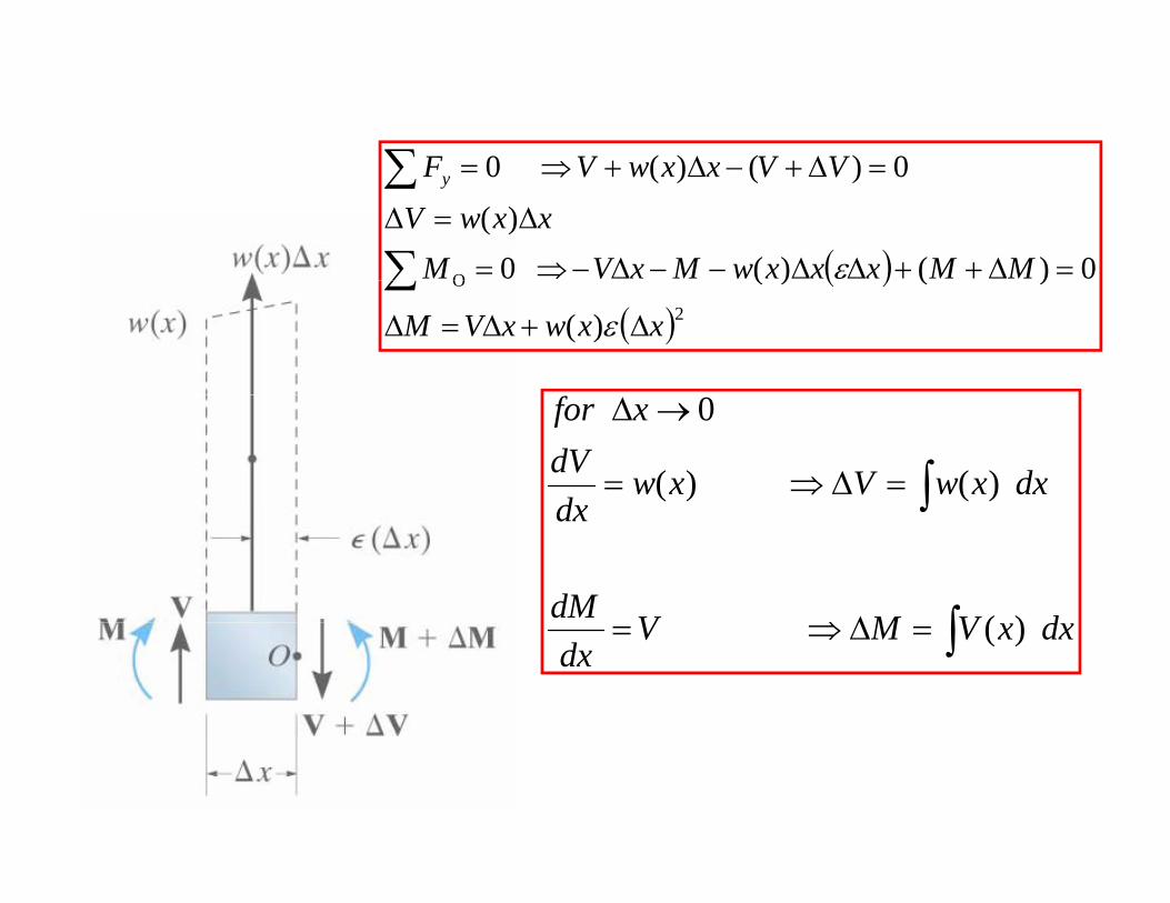
0)()(0 VVxxwVF =∆+∆+⇒=∑
( )O 0)()( 0)(
0)()(0
MMxxxwMxVMxxwV
VVxxwV Fy
=∆++∆∆−−∆−⇒=
∆=∆
=∆+−∆+⇒=
∑
∑
ε( )( )2
O
)(
)()(
xxwxVM ∆+∆=∆
∑ε
∫=∆⇒=
→∆
dxxwVxwdxdV
xfor
)( )(
0
∫
∫
∆⇒ dVMVdM
dx
)(∫=∆⇒= dxxVMVdx
)(
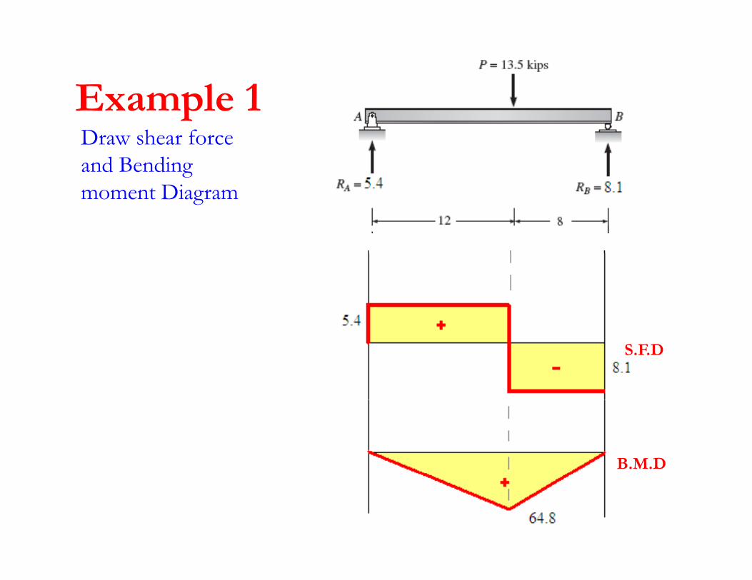
Example 1Example 1Draw shear force and Bending moment Diagram
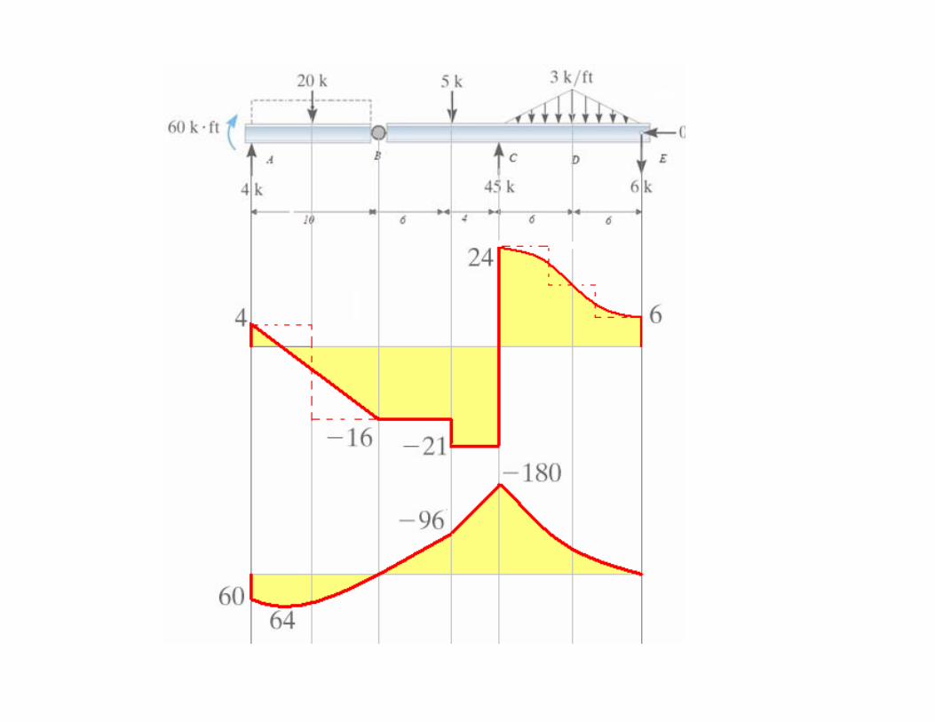
S.F.D
B.M.D
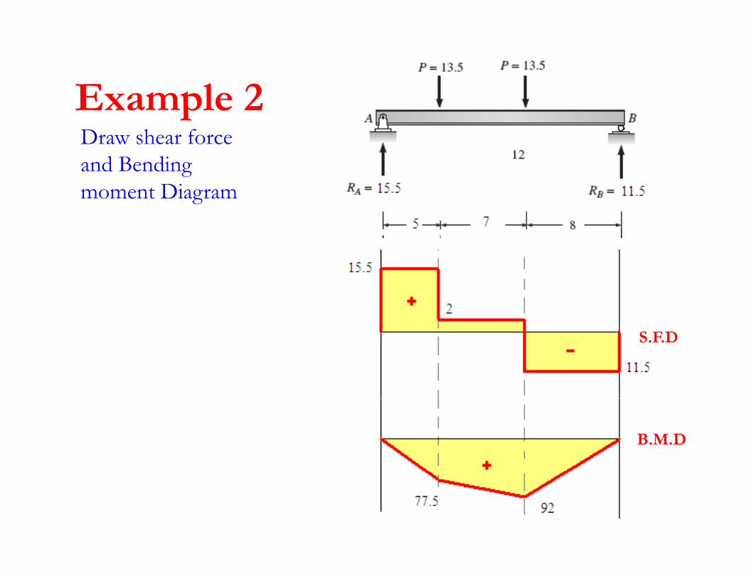
Example 2Example 2Draw shear force and Bending moment Diagram
S.F.D
B.M.D
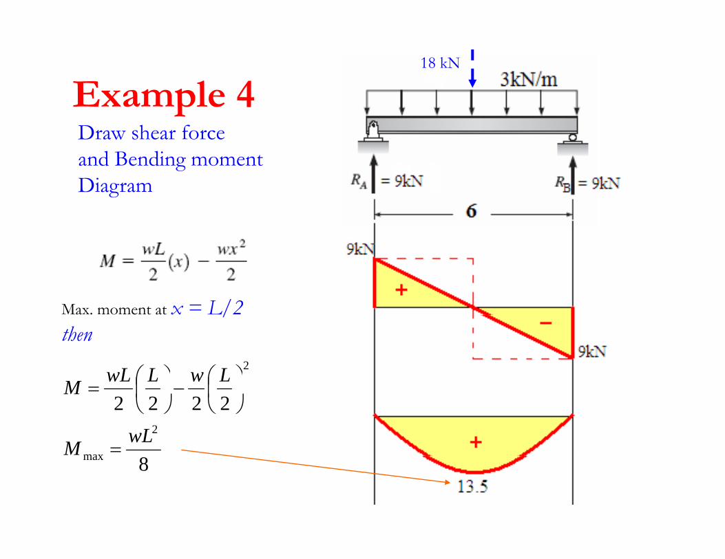
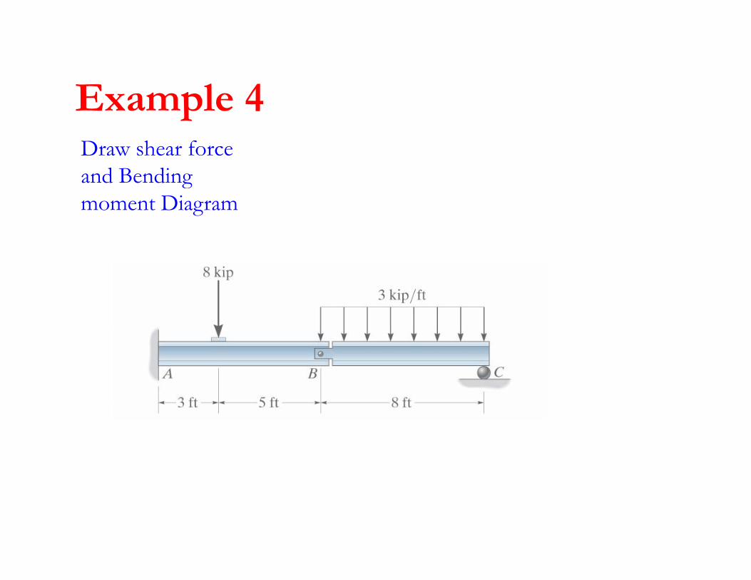
Example 418 kN
Example 4Draw shear force and Bending moment Diagram
Max. moment at x = L/2/then
2LwLwLM ⎞⎜⎛⎞
⎜⎛
22222
maxwLM
M
=
⎠⎜⎝
−⎠
⎜⎝
=
8max
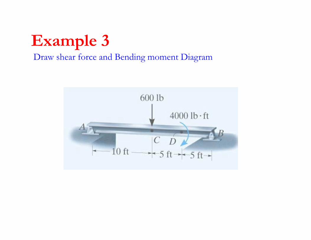
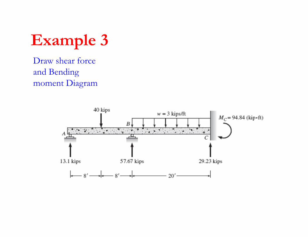
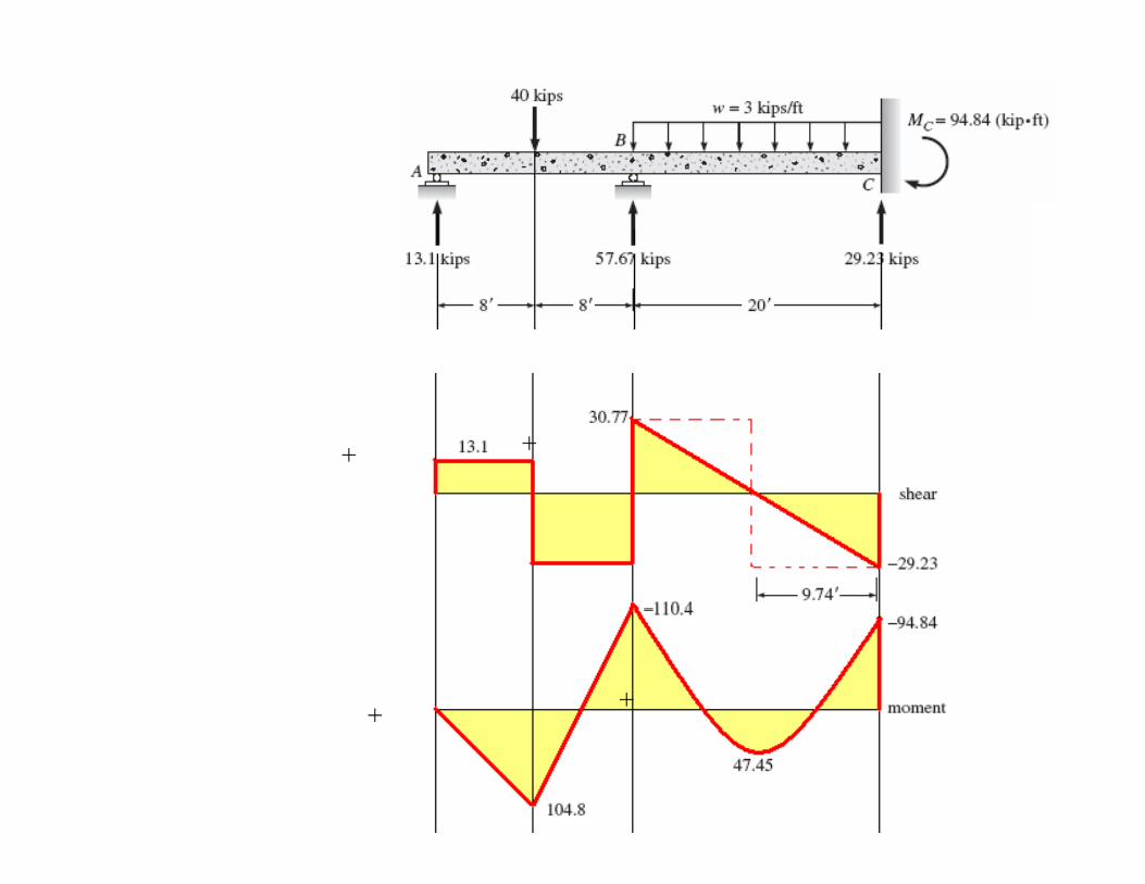
Example 3Example 3Draw shear force and Bending moment Diagram
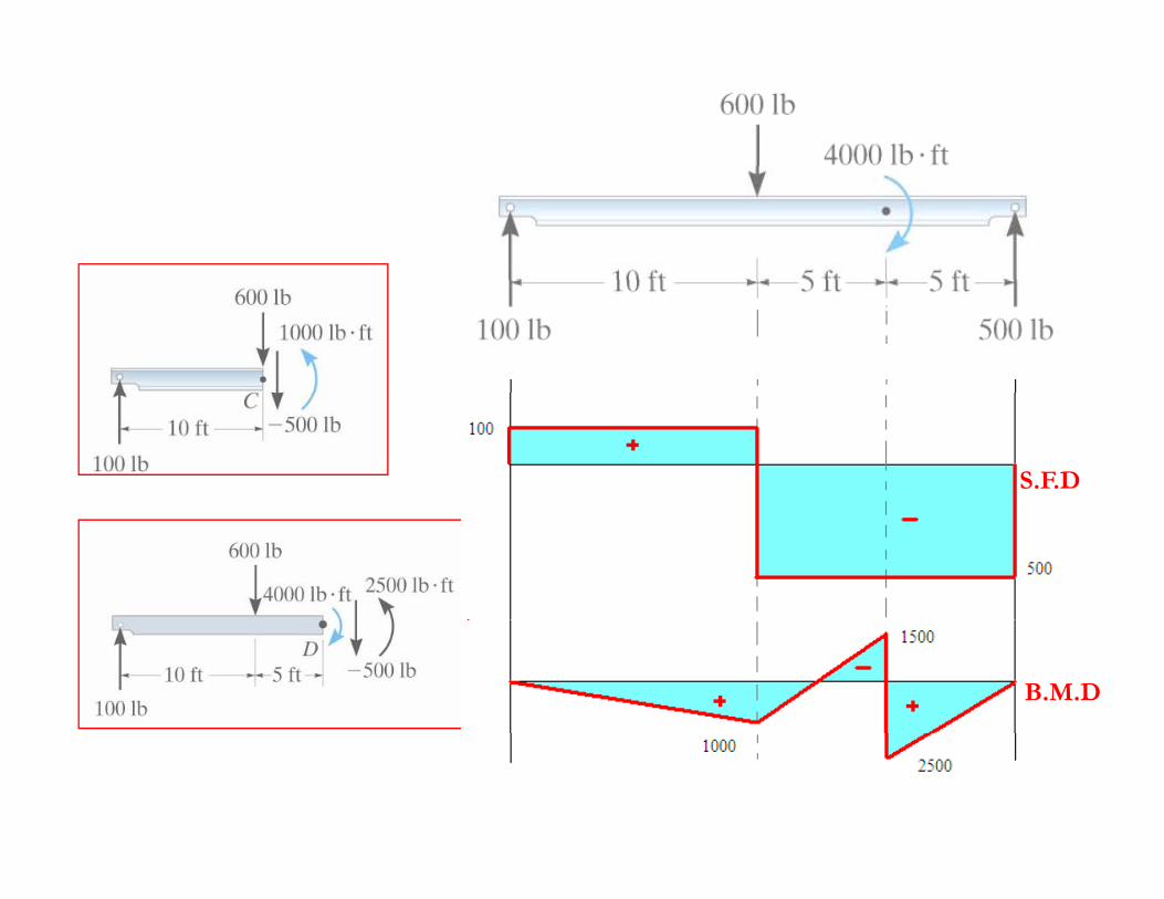
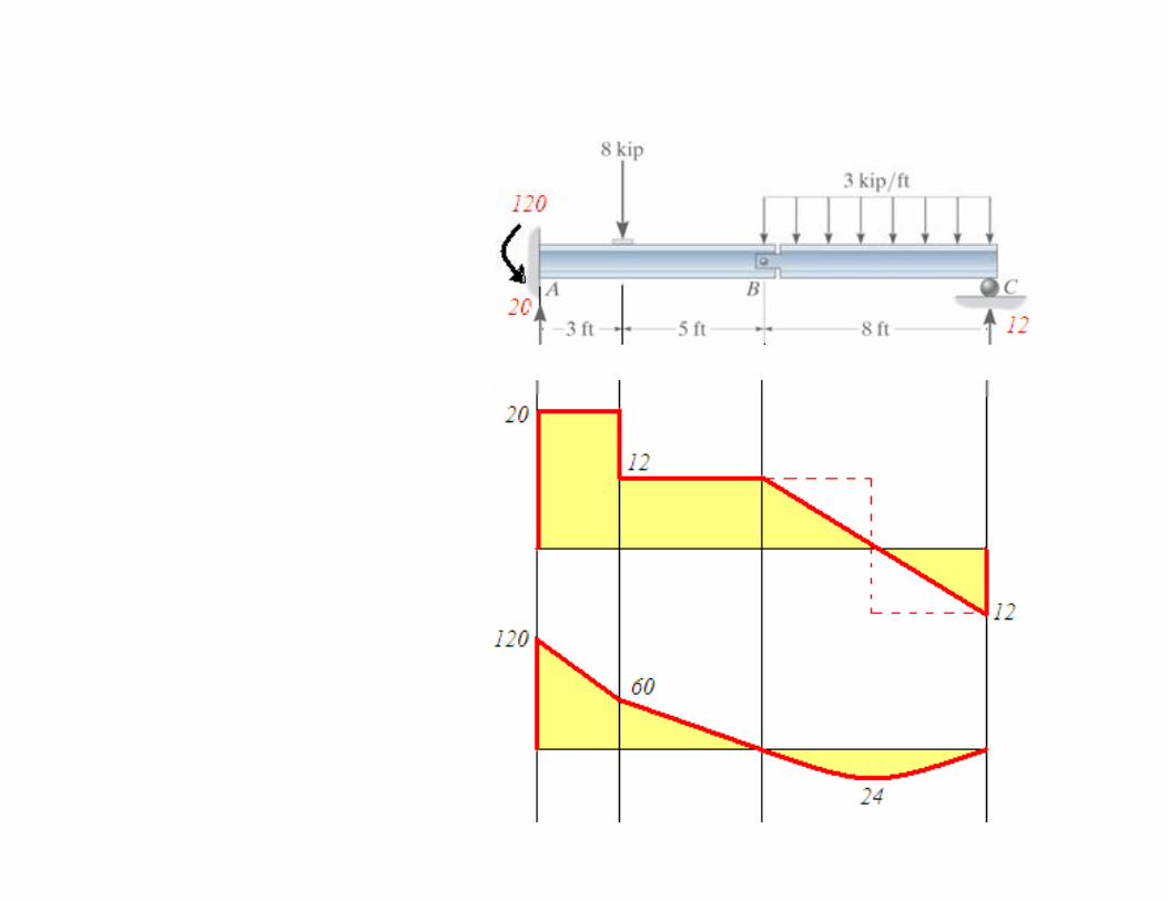
S.F.D
B.M.D

D h fExample 5
Draw shear force and Bending moment Diagramg
)7(14)53(147142
+−−=
==
∑ MMx
x
49
)7(14)5.3(14
=
+∑M
MMS
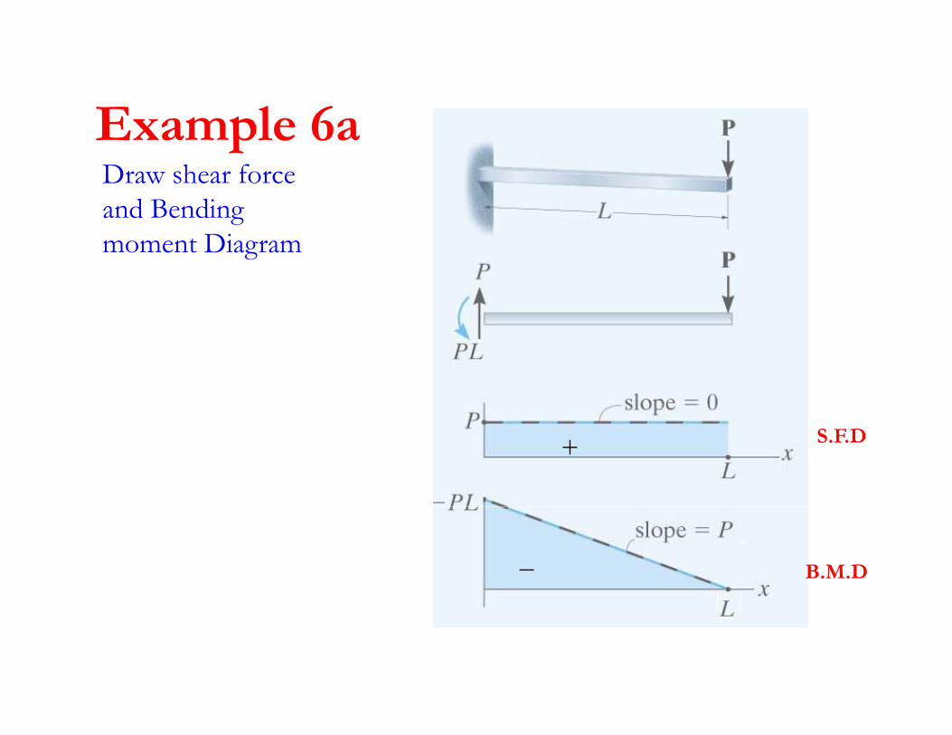
Example 6aExample 6aDraw shear force and Bending moment Diagram
S.F.D
B.M.D
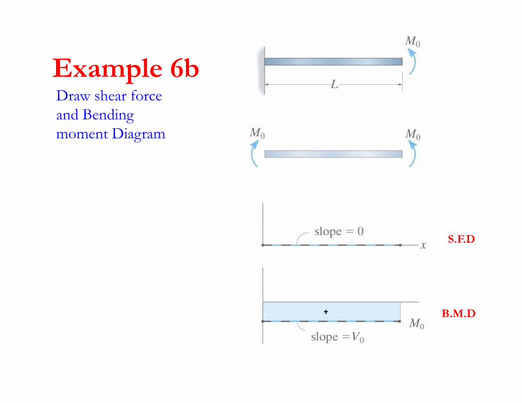
Example 6bExample 6bDraw shear force and Bending moment Diagram
S.F.D
B.M.D
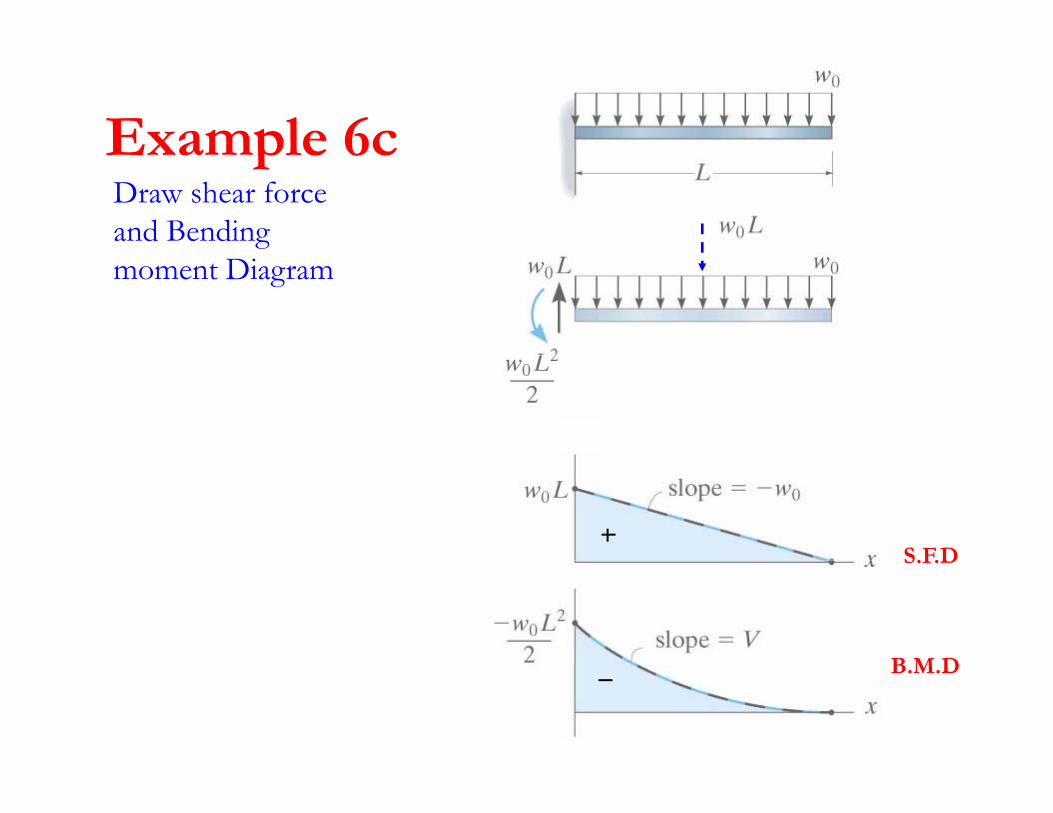
Example 6cExample 6cDraw shear force and Bending moment Diagram
S.F.DS.F.D
B M DB.M.D
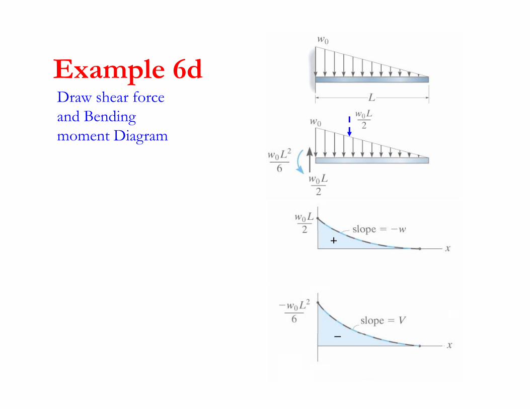
Example 6dExample 6dDraw shear force and Bending moment Diagram
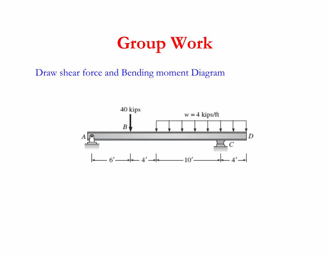
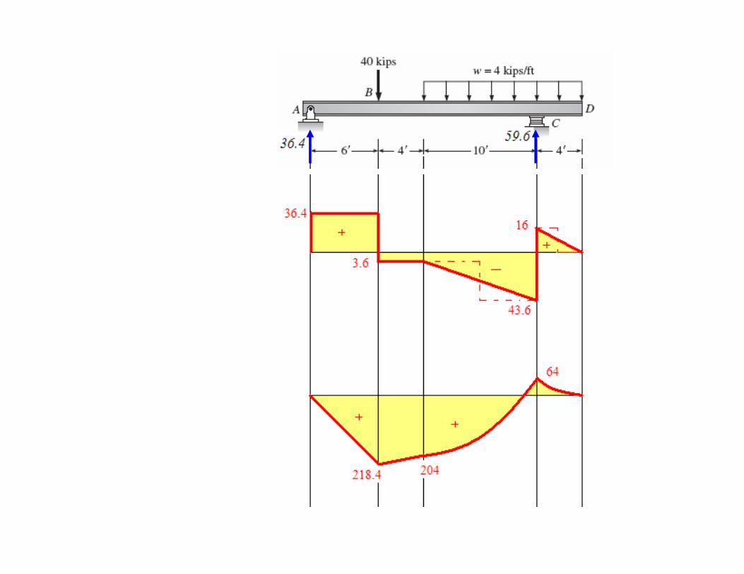
Group WorkGroup Work
Draw shear force and Bending moment Diagram
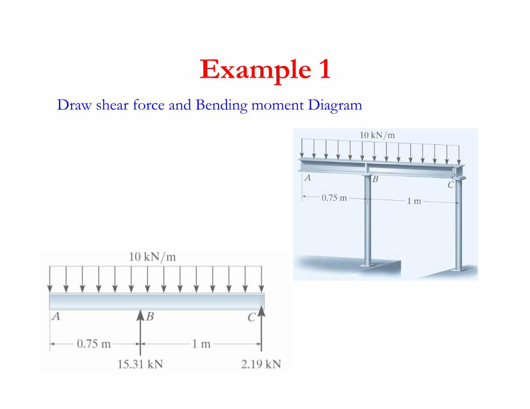
Example 1Draw shear force and Bending moment Diagram
Example 1
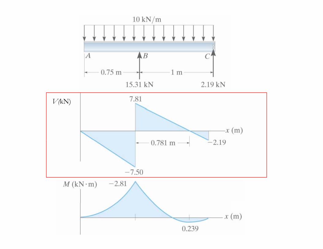
V(kN)
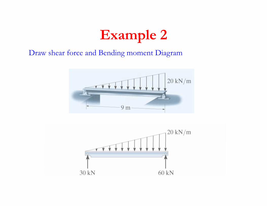
Example 2Example 2Draw shear force and Bending moment Diagram
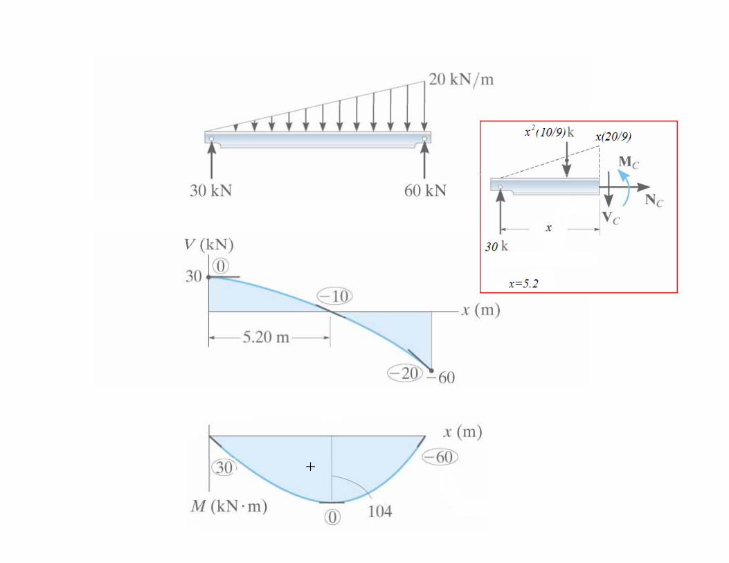
+
Example 2Example 2Draw shear force and Bendingand Bending moment Diagram
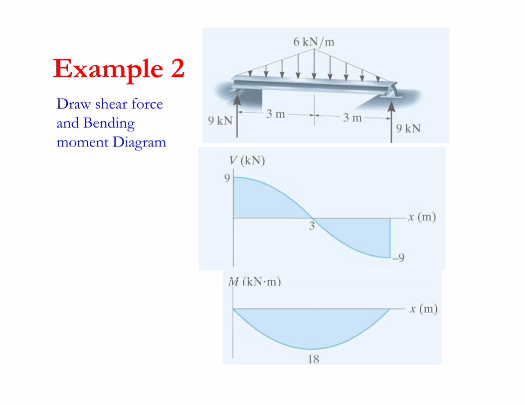
Example 3Example 3Draw shear force and Bendingand Bending moment Diagram
++
+ ++
Example 4Example 4Draw shear force and Bendingand Bending moment Diagram
++
+
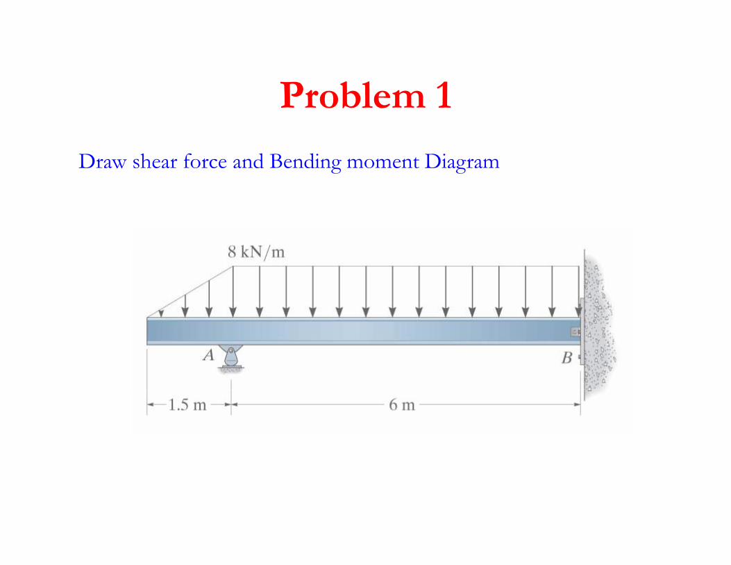
Problem 1Problem 1
Draw shear force and Bending moment Diagram
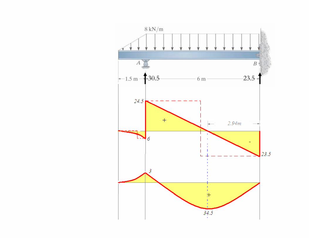
30.5 23.5
+
--
+ ++
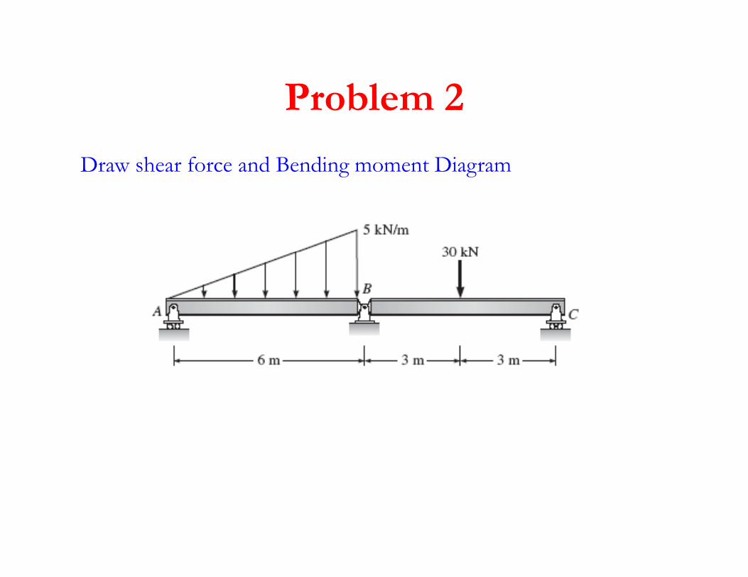
Problem 2Problem 2
Draw shear force and Bending moment Diagram
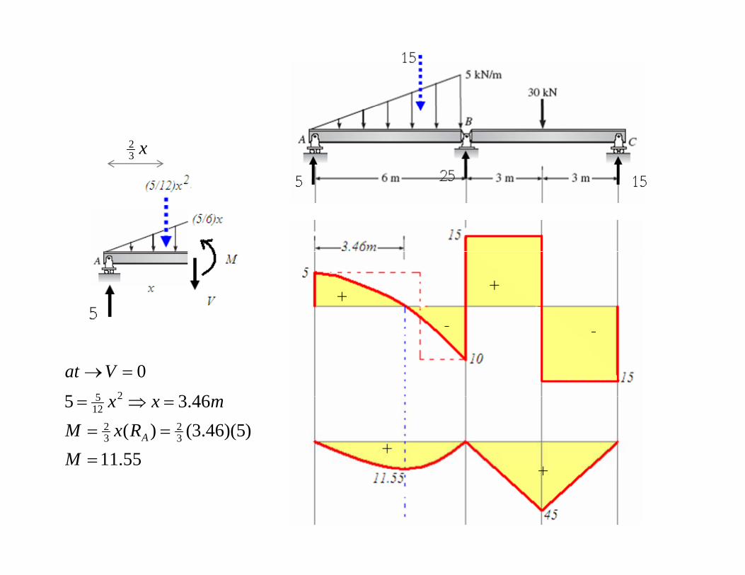
x32
46350
25
=→Vat
55.11)5)(46.3()(
46.35
32
32
2125
=
==
=⇒=
MRxM
mxx
A
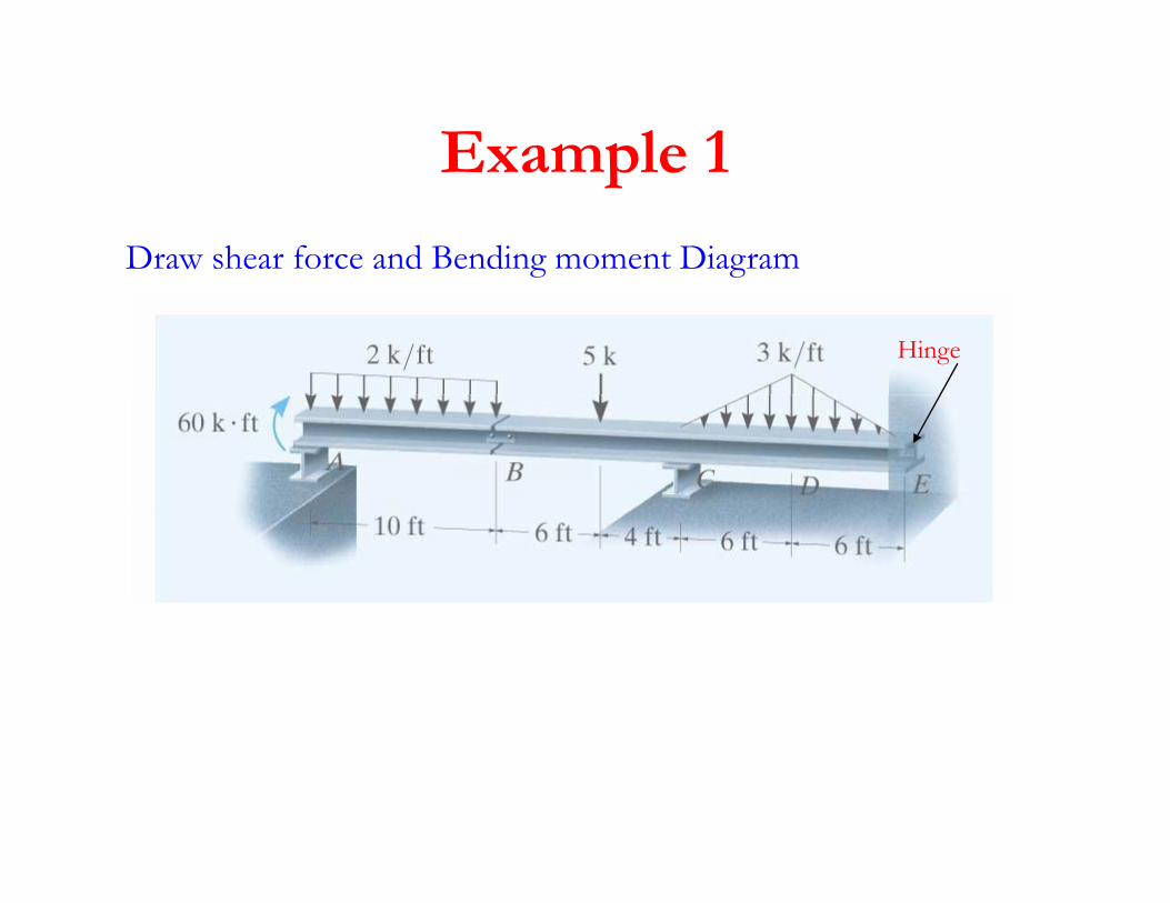
Example 1Example 1
Draw shear force and Bending moment Diagram
Hinge
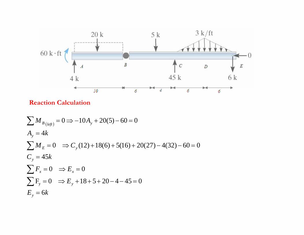
Reaction Calculation
( )
kA
AM yleftB
4
060)5(20100 =−+−⇒=∑
Reaction Calculation
kC
CM
kA
y
yE
y
45
060)32(4)27(20)16(5)6(18)12( 0
4
=
=−−+++⇒=
=
∑
kE
E
EF
y
xx
6
045420518 0F
0 0
y =−−+++⇒=
=⇒=
∑∑
kEy 6=
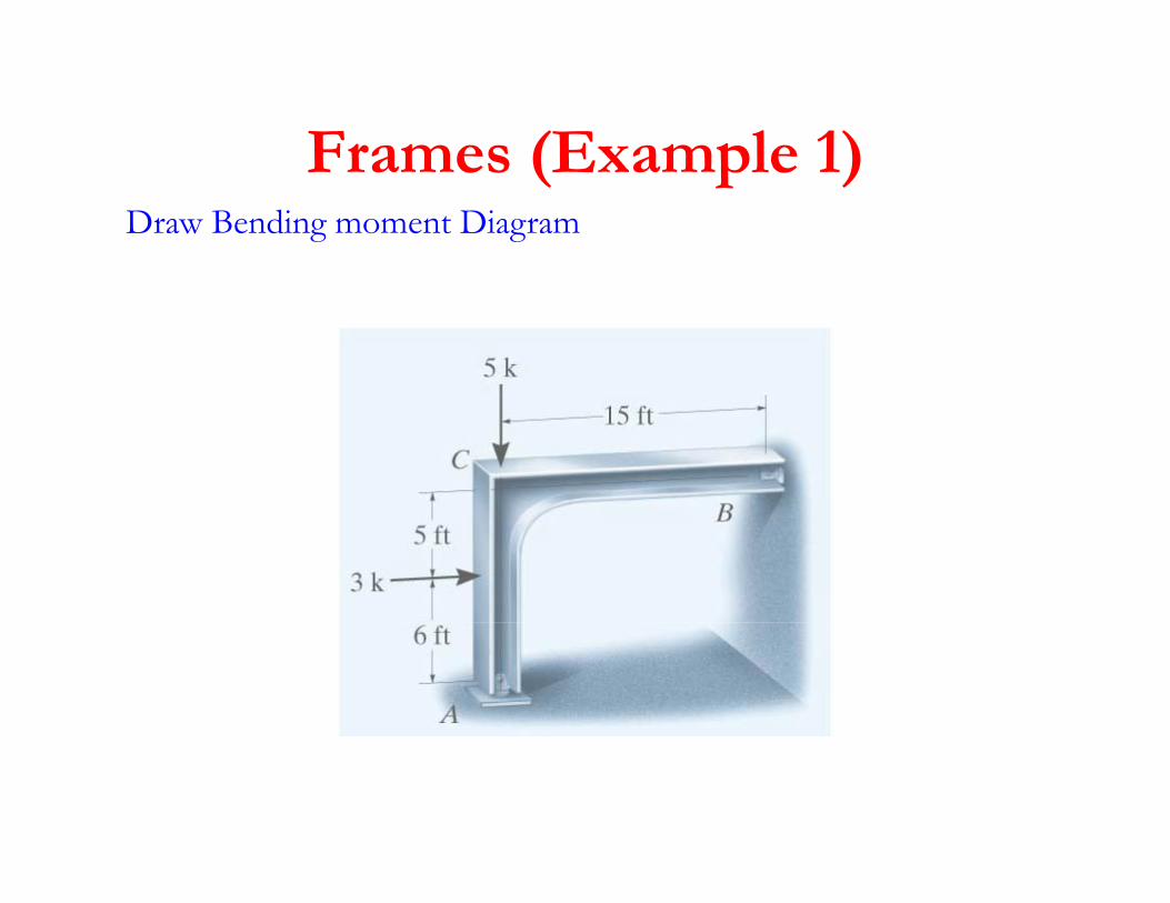
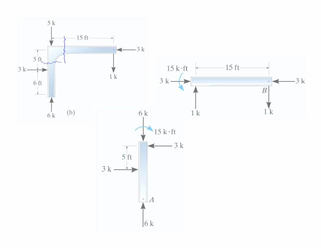
Frames (Example 1)Frames (Example 1)Draw Bending moment Diagram
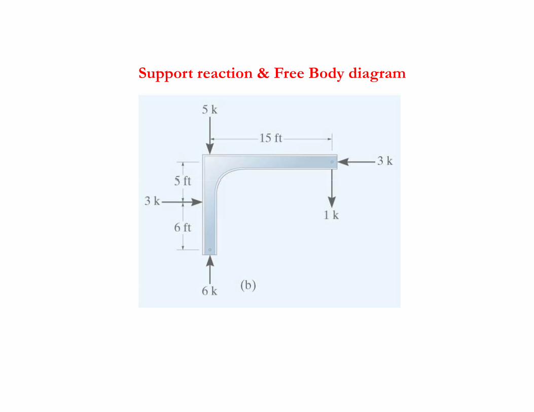
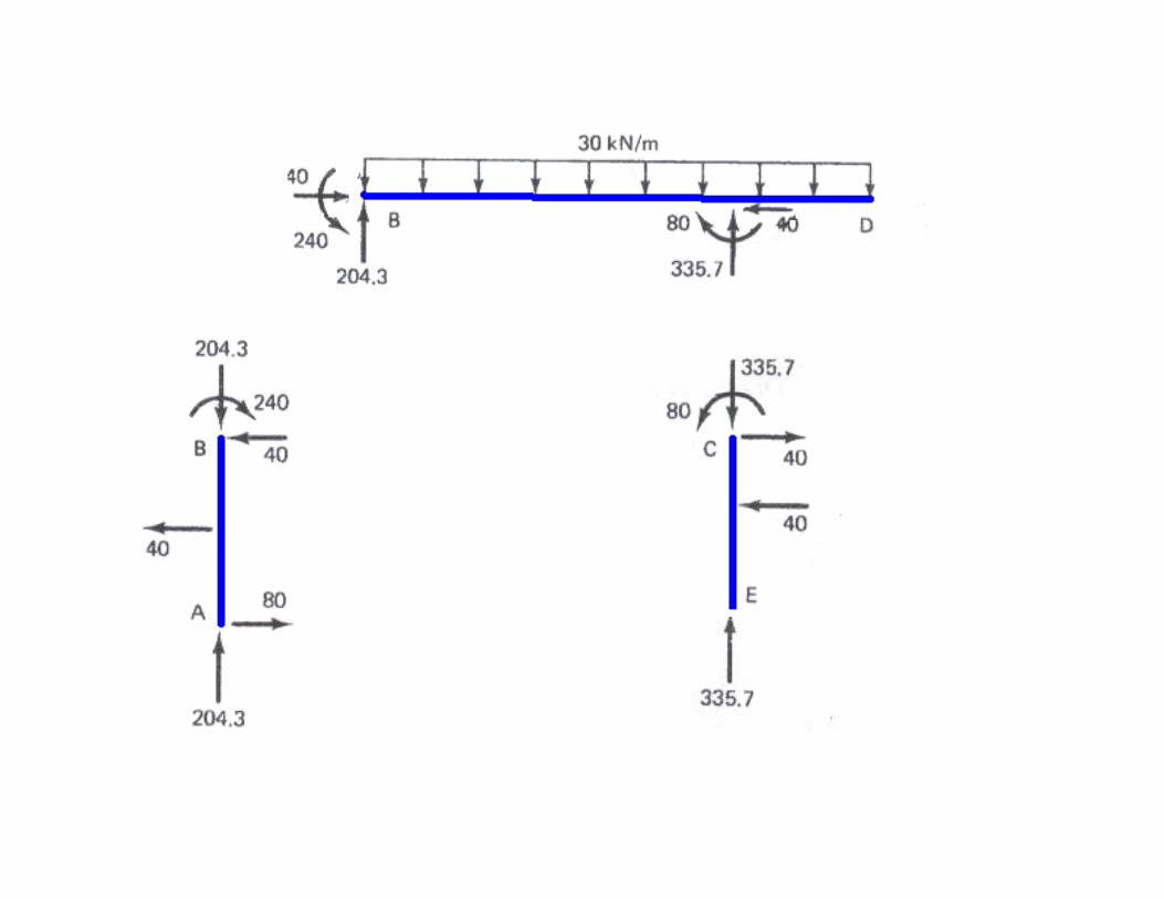
Support reaction & Free Body diagramSupport reaction & Free Body diagram
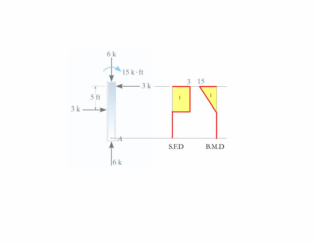
_ _
S.F.D B.M.D
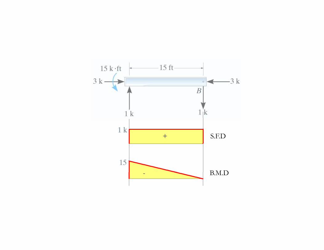
++ S.F.D
- B M D- B.M.D
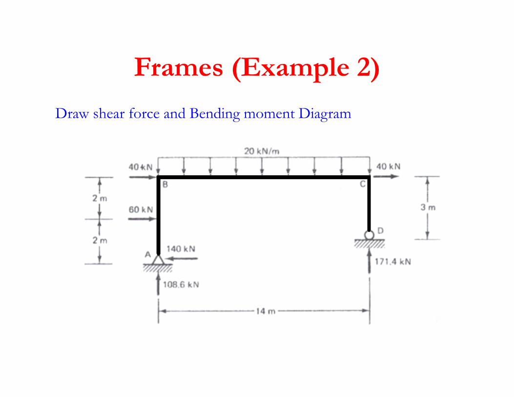
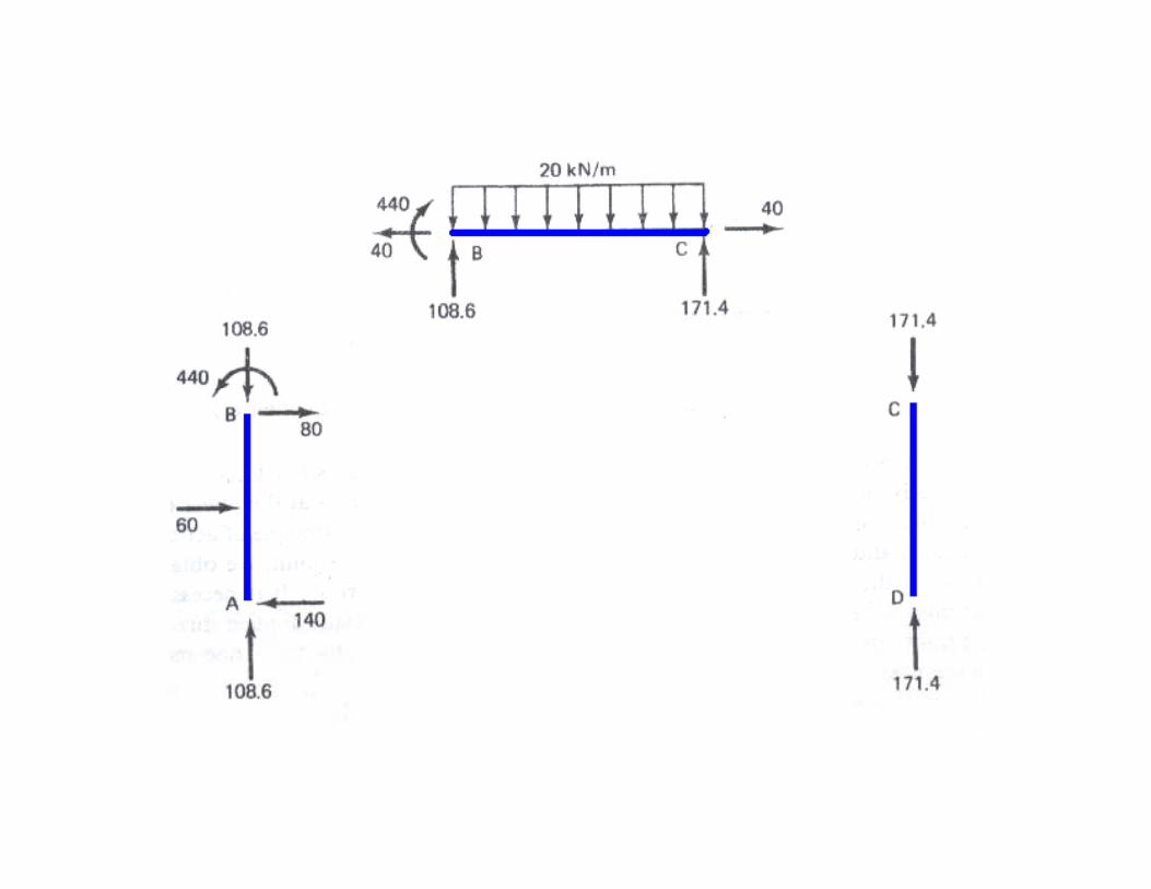
Frames (Example 2)Frames (Example 2)
Draw shear force and Bending moment Diagram
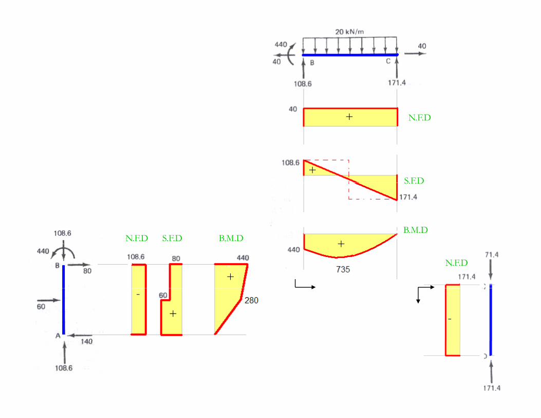
N.F.D+
S.F.D+
B M DN FD S FD B M DN FD S FD
S.F.D
B.M.D
_
B.M.DN.F.D S.F.D B.M.DN.F.D S.F.D
+
+N.F.D
+
-
-
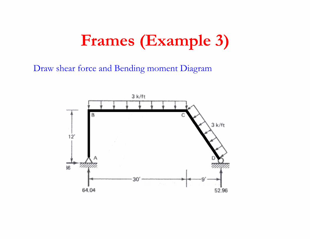
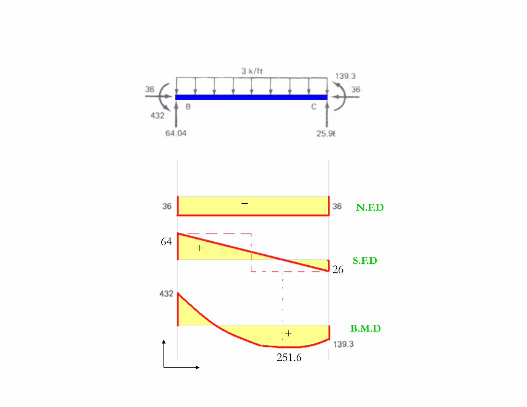
Frames (Example 3)Frames (Example 3)
Draw shear force and Bending moment Diagram
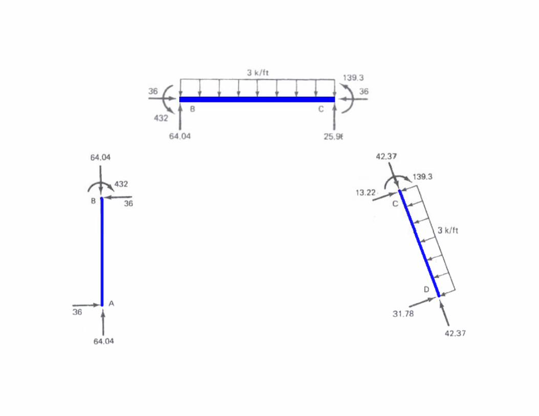
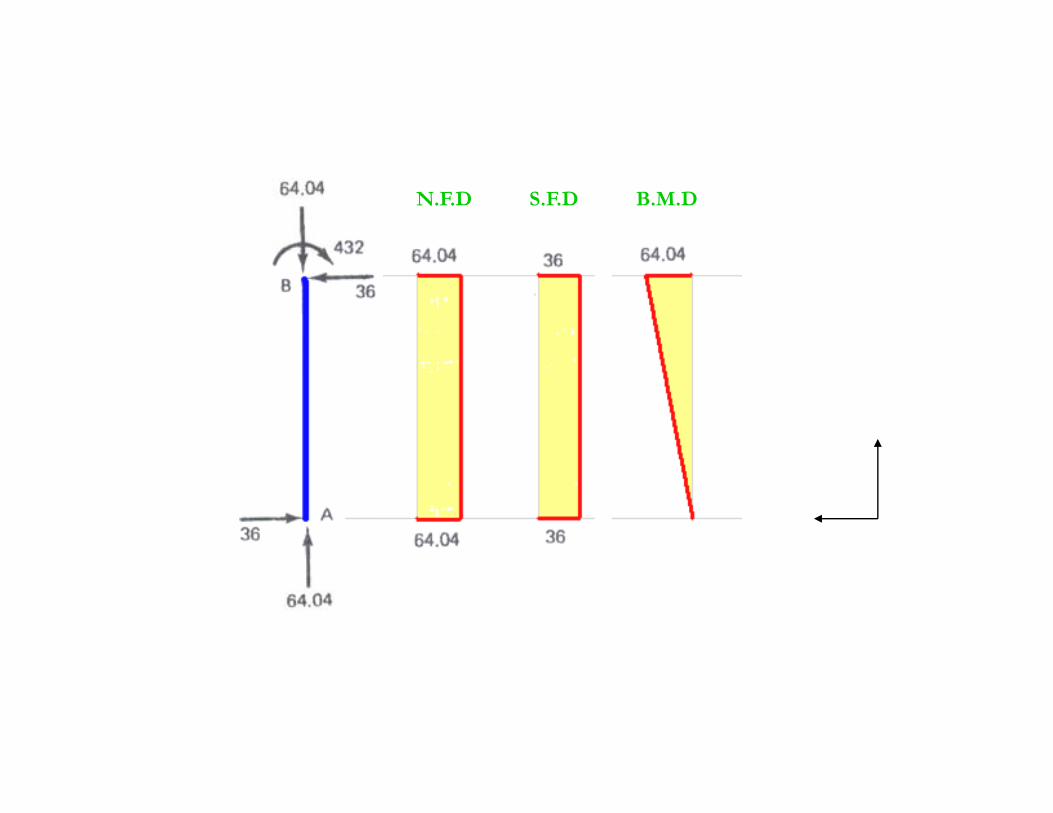
B.M.DN.F.D S.F.D
-
--
_N.F.D
+S.F.D
64
26
+ B.M.D+
251.6
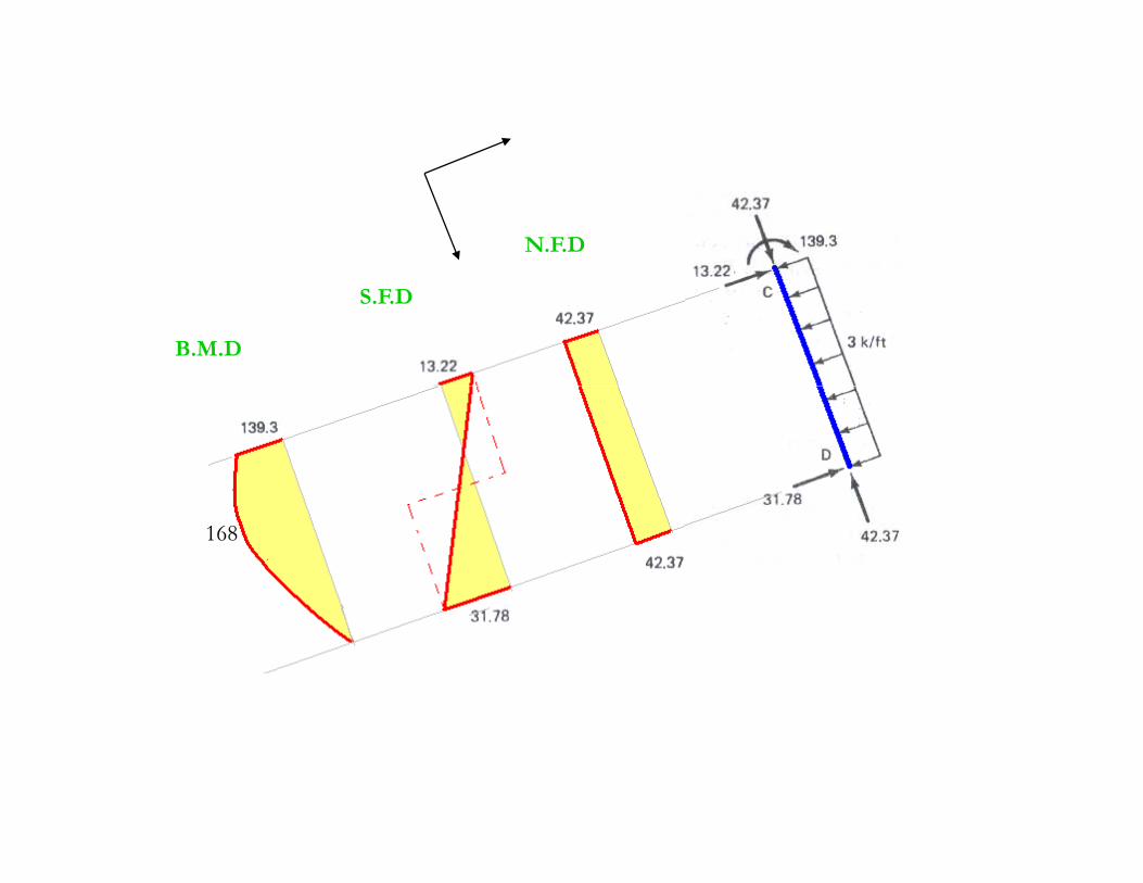
N.F.D
B.M.D
S.F.D
168
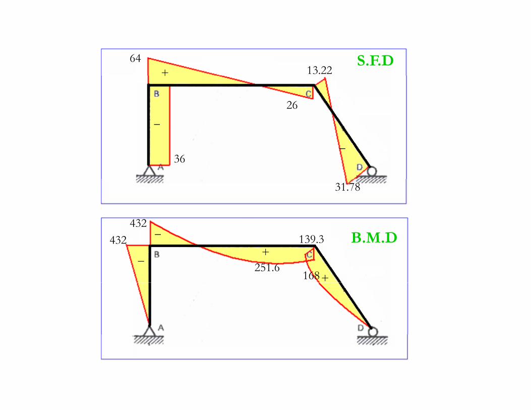
S.F.D6413.22+
26
+
_
36_
432
31.78
B.M.D
168
432 139.3
251.6+
_
_
+
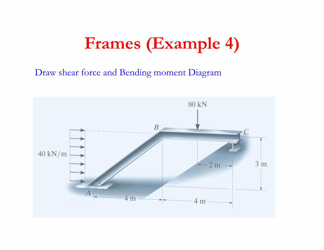
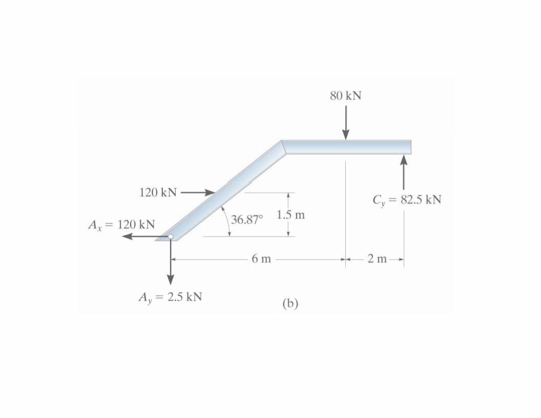
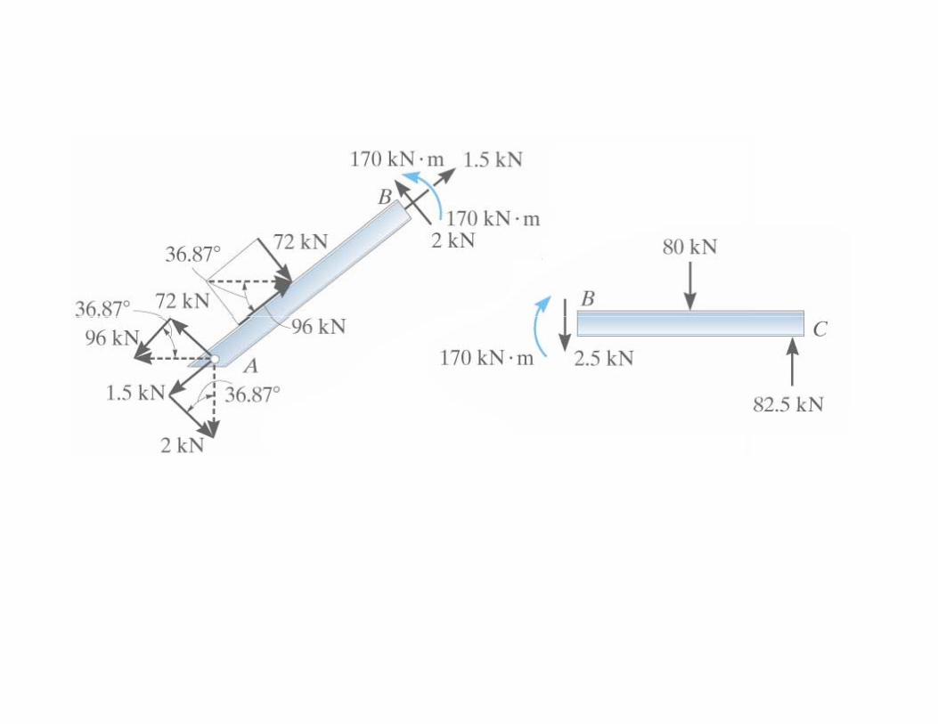
Frames (Example 4)Frames (Example 4)
Draw shear force and Bending moment Diagramg g
S.F.D
B.M.D
+
+
S.F.D_
B.M.D+
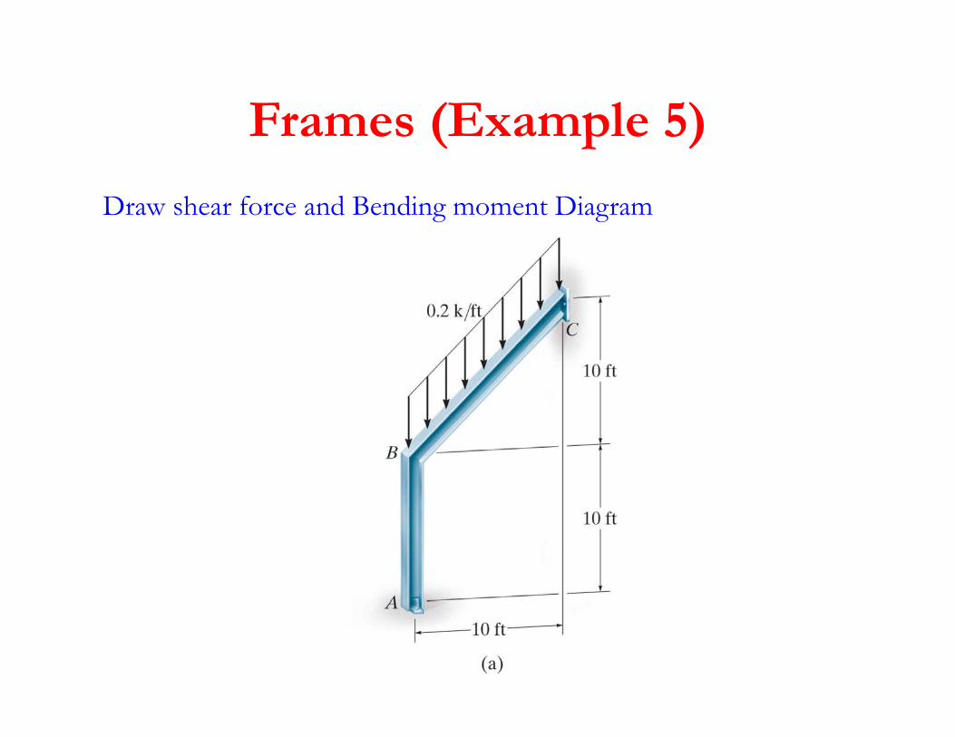
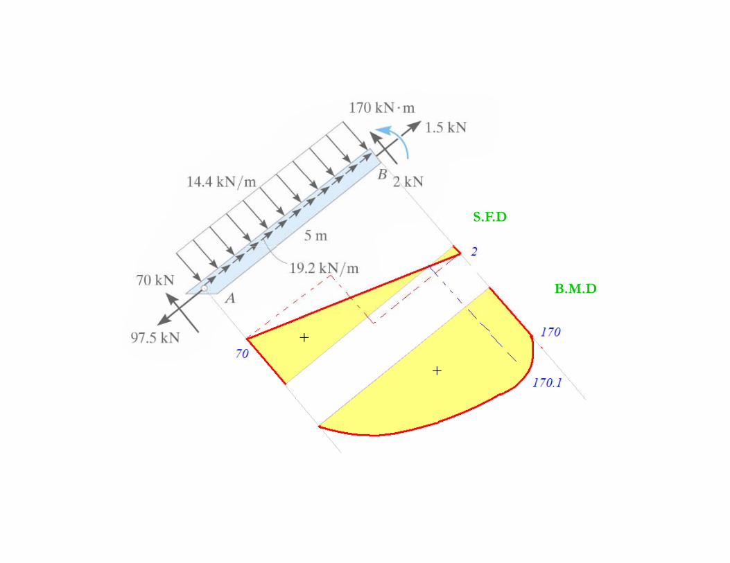
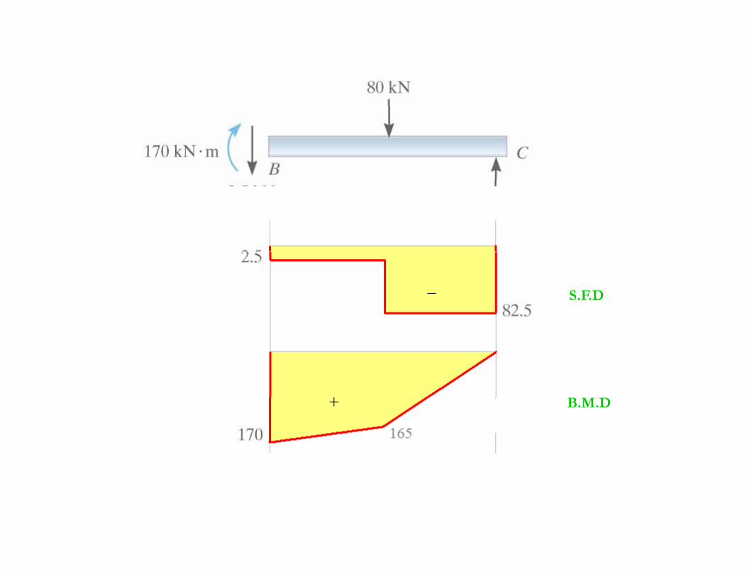
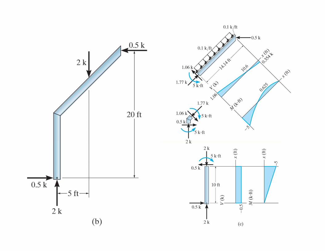
Frames (Example 5)a es ( a p e 5)
Draw shear force and Bending moment Diagram
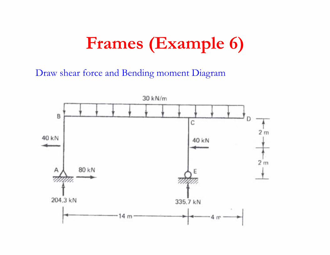
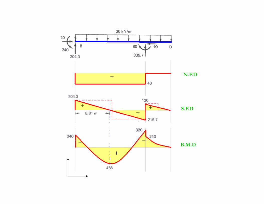
Frames (Example 6)Frames (Example 6)
Draw shear force and Bending moment Diagram
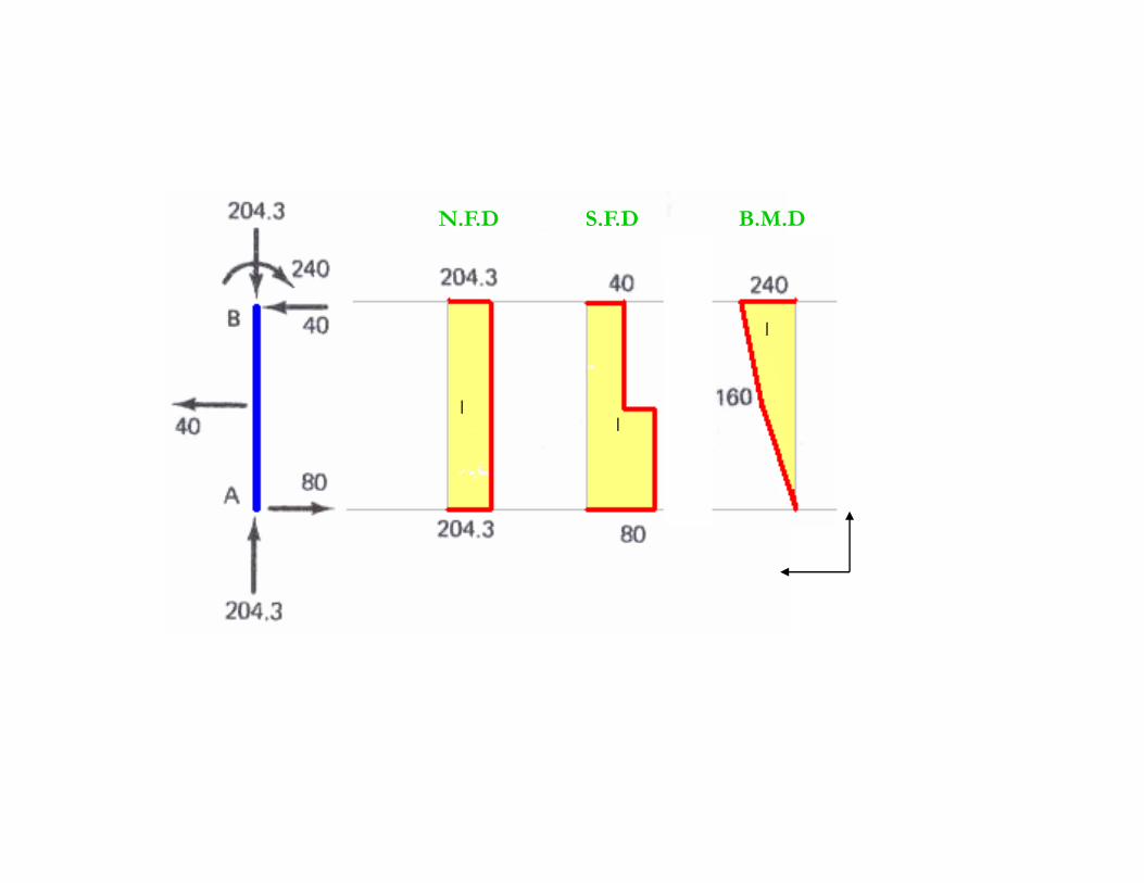
N.F.D S.F.D B.M.D
_
_
_
_ N.F.D
+_ + S.F.D
+
__B.M.D
N.F.DS.F.DB.M.D
_
+
_
_
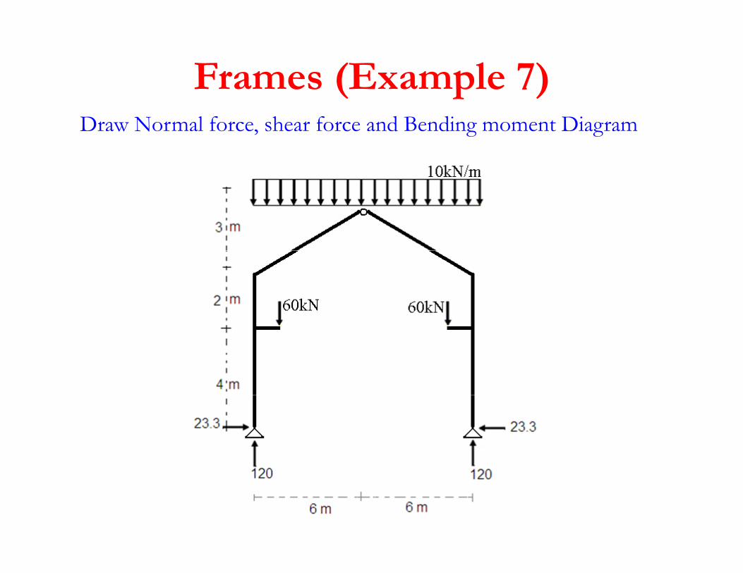
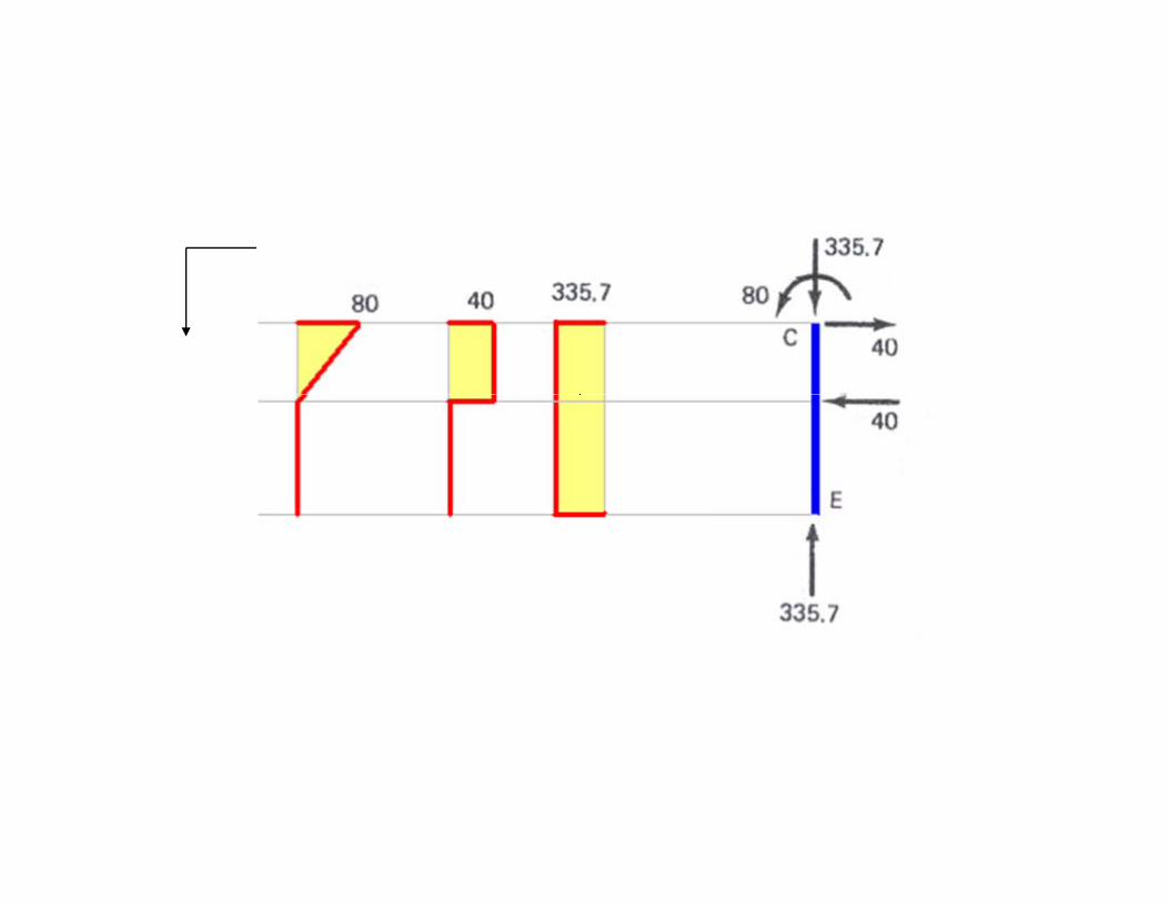
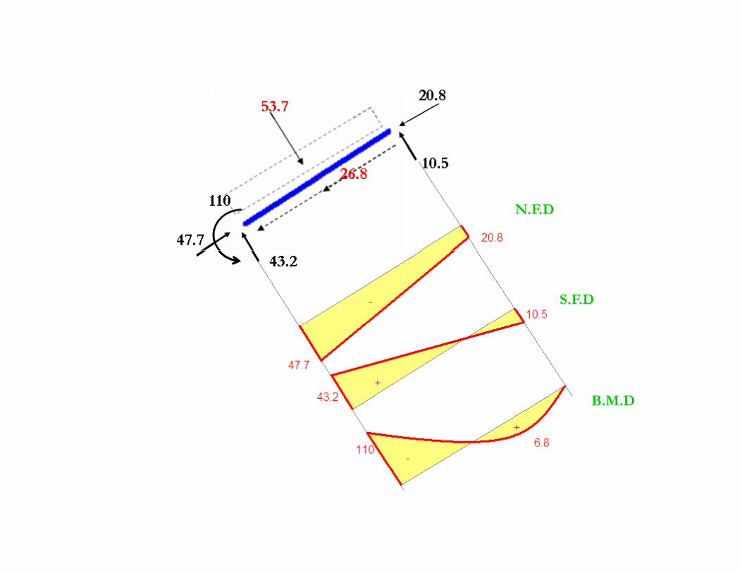
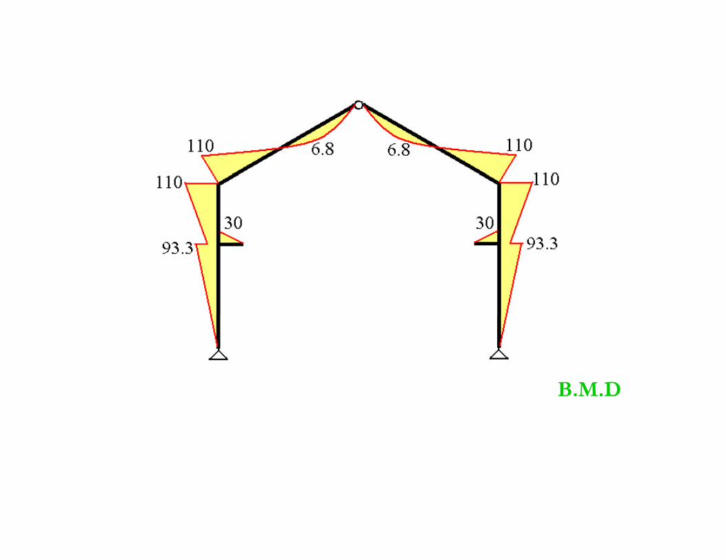
Frames (Example 7)Draw Normal force, shear force and Bending moment Diagram
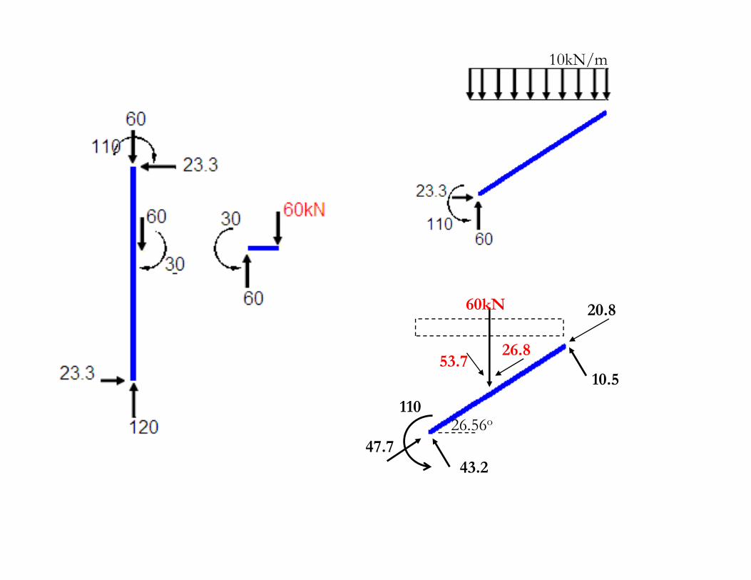
10kN/m
60kN 20.8
53.726.8
10.5
26.56o
47.743.2
110
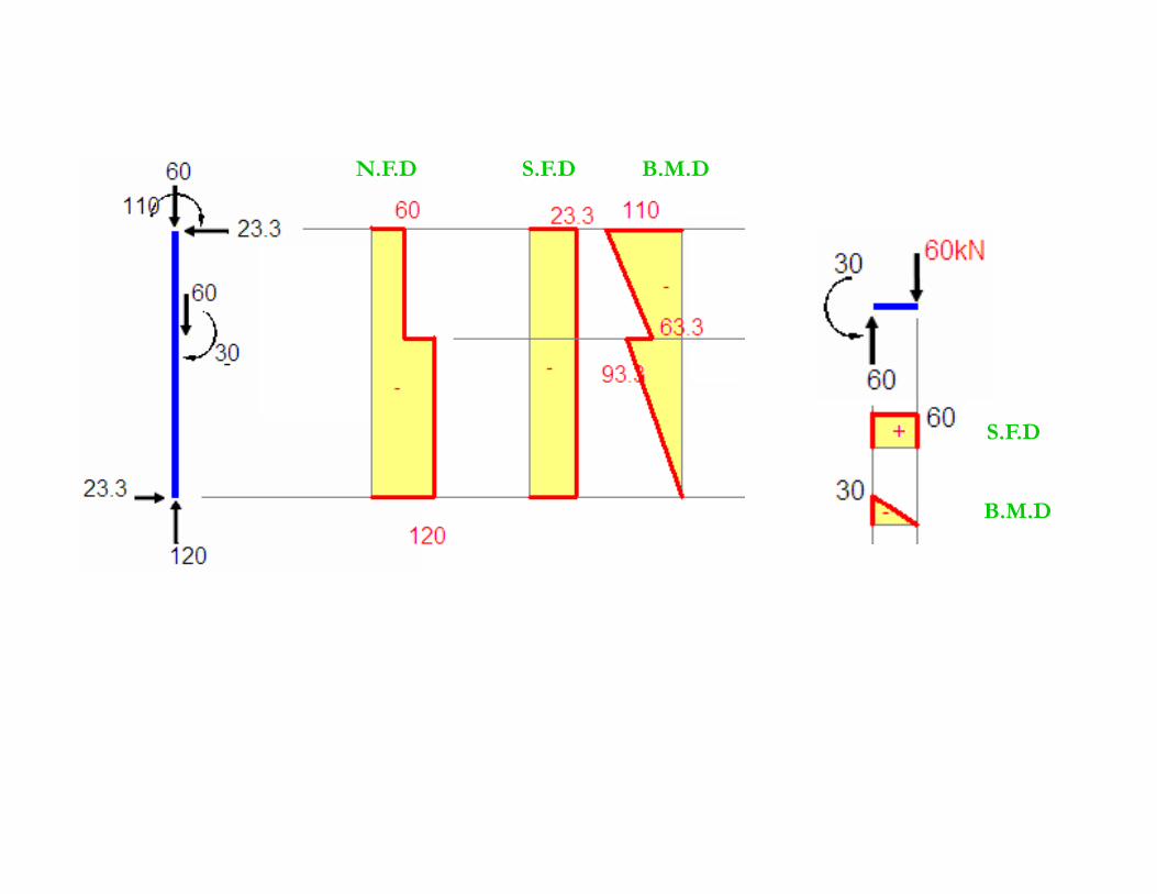
N F D S F D B M DN.F.D S.F.D B.M.D
S.F.D
B M DB.M.D
N.F.D
S.F.D
B.M.D
B M DB.M.D
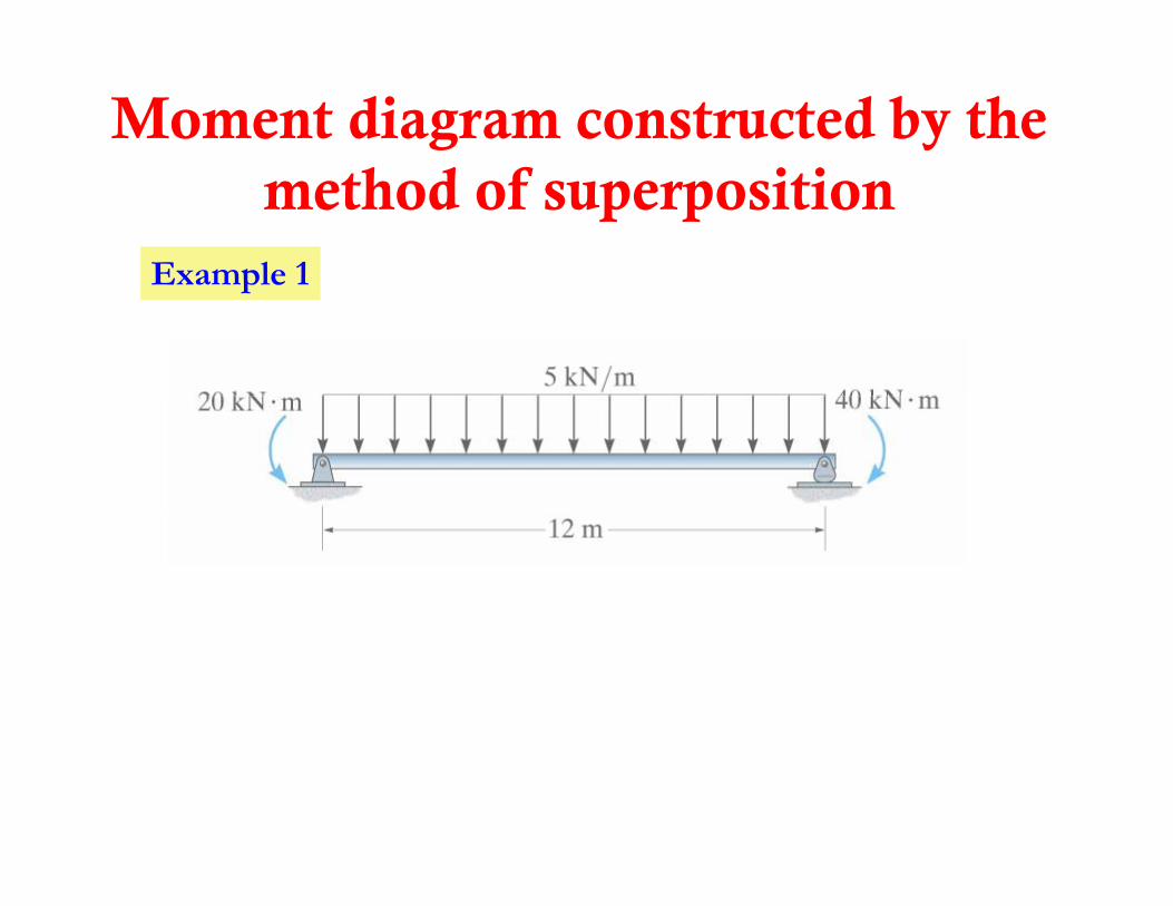
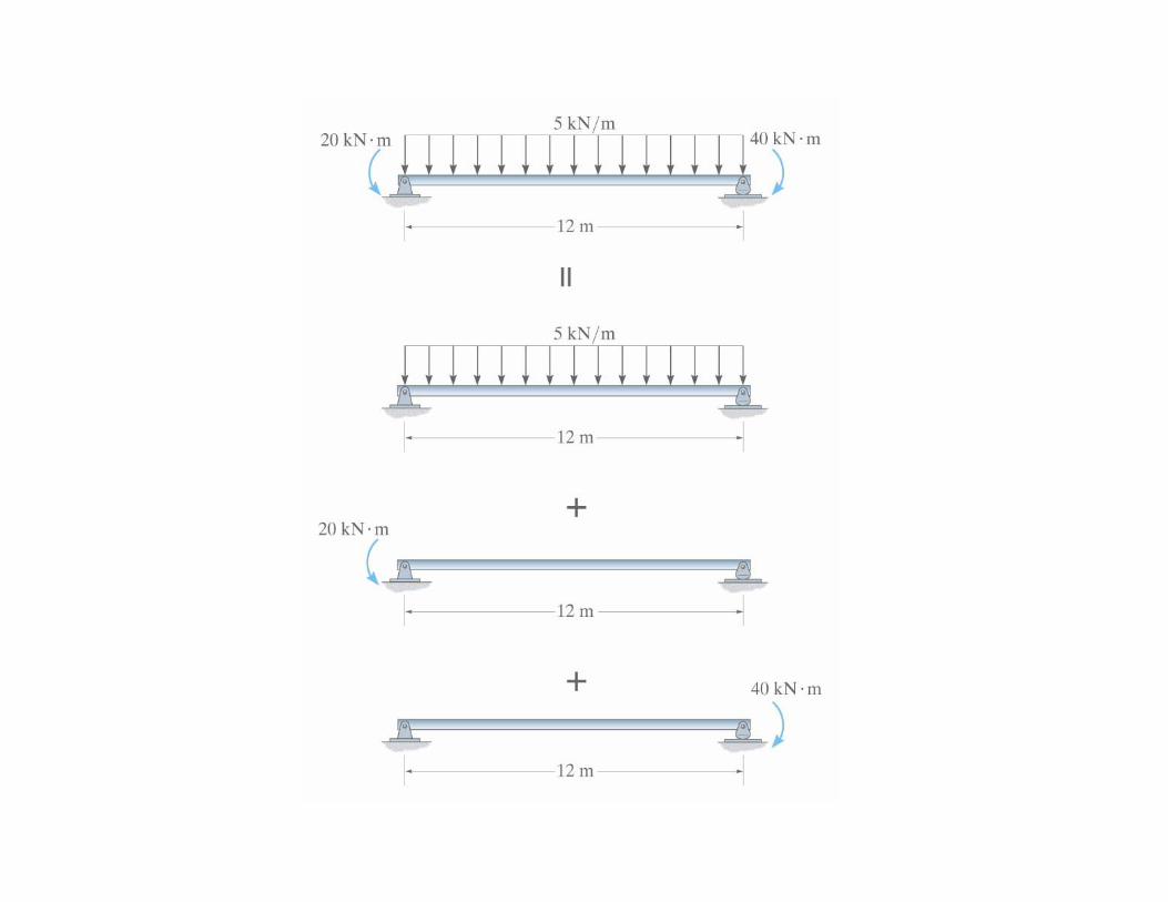
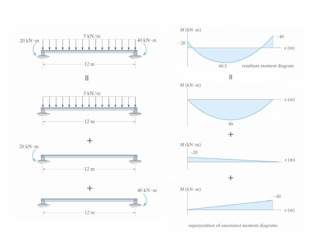
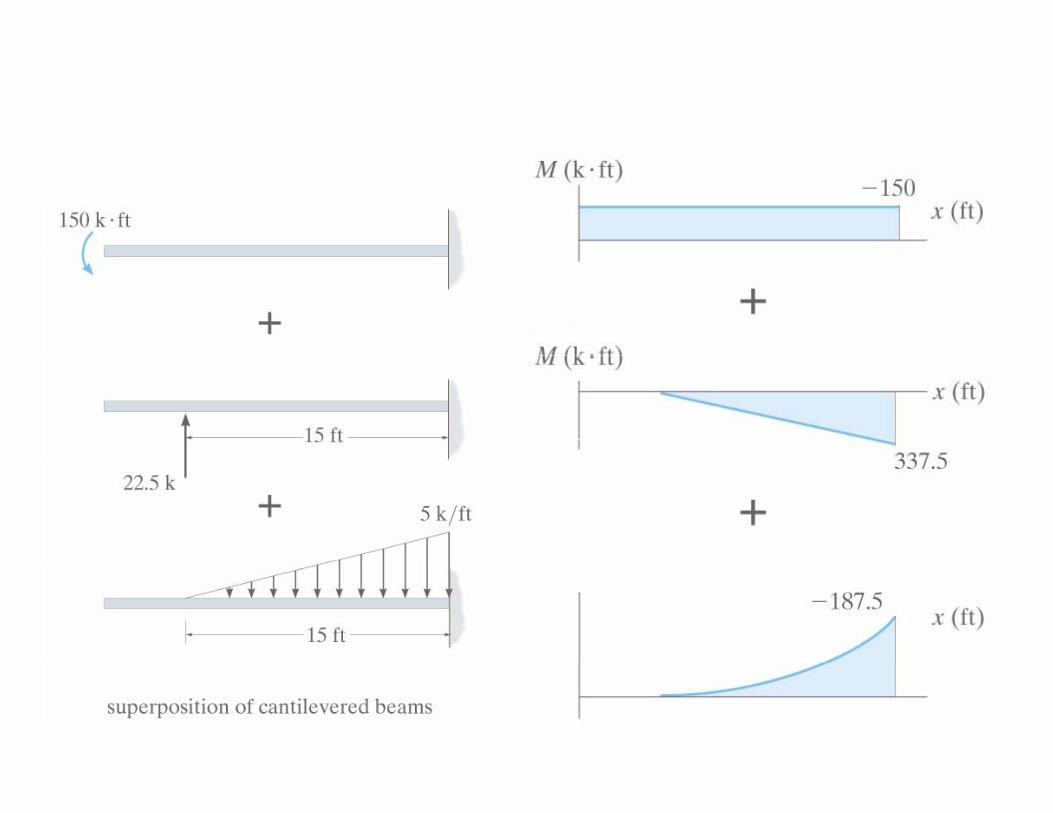
Moment diagram constructed by the h d f i imethod of superposition
Example 1Example 1
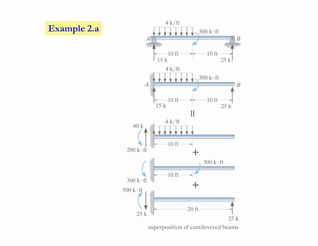
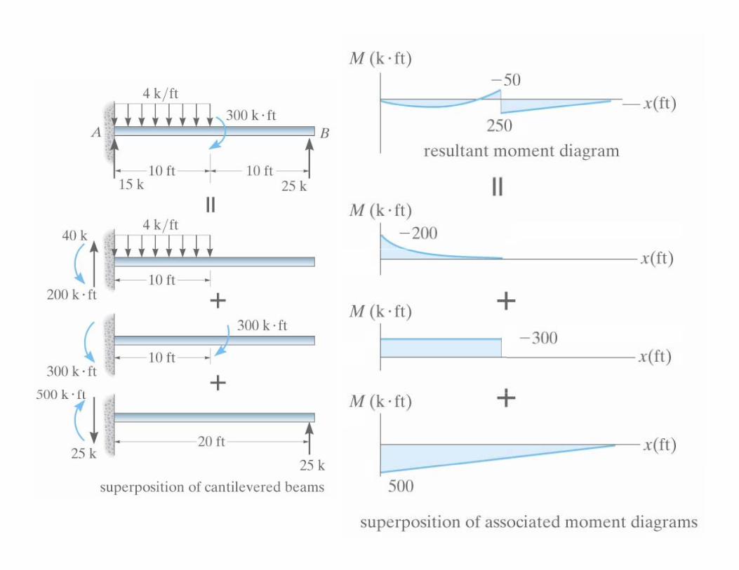
Example 2.a
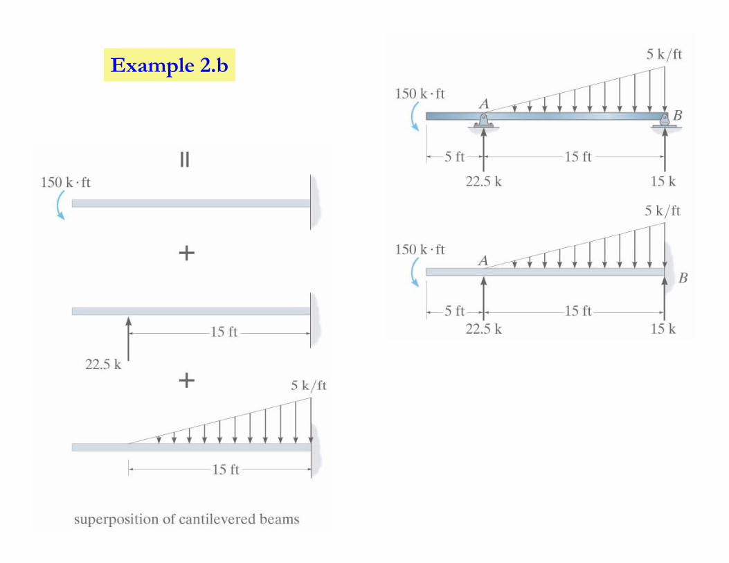
Example 2.b
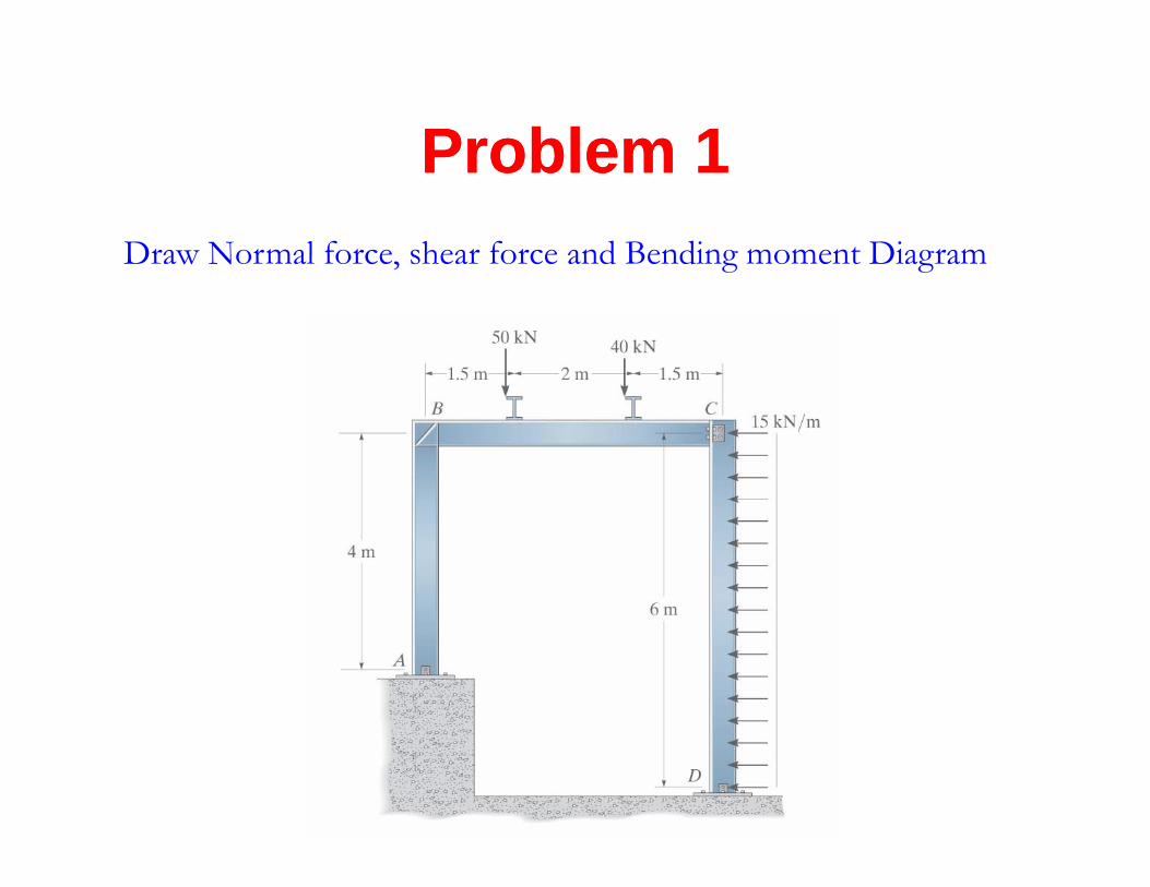
ProblemProblem 11Problem Problem 11Draw Normal force, shear force and Bending moment Diagram
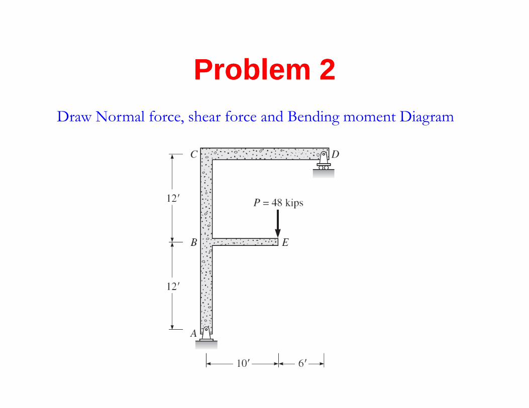
ProblemProblem 22Problem Problem 22Draw Normal force, shear force and Bending moment Diagram