study guide - cisco网络技术(net130.com) study guide building...642-821 bcran v2.0 leading the...
TRANSCRIPT

642-821 BCRAN v2.0
Leading the way in IT testing and certification tools, www.testking.com
- 1 -
642-821
Study Guide
Building Cisco Remote Access Networks v2.0
(BCRAN) Version 1.1

642-821 BCRAN v2.0
Leading the way in IT testing and certification tools, www.testking.com
- 2 -
TABLE OF CONTENTS List of Tables List of Acronyms Introduction 1. Cisco Remote Connection Products
1.1 Router Selection Criteria
1.2 Selecting a WAN Connection Type
1.3 Determining the Site Requirements 1.3.1 Central Office Installations 1.3.2 Branch Office Installations 1.3.3 Remote Office or Home Office Installations
1.4 Hardware Selection
2. Assembling and Cabling WAN Components
2.1 Choosing WAN Equipment 2.1.1 Central Office Router Selection
2.1.1.1 The 3600/3700 Router Series 2.1.1.2 The 4000 Router Series 2.1.1.3 The AS5X00 Router Series 2.1.1.4 The 7200/7500 Router Series
2.1.2 Branch Office Router Selection 2.1.2.1 The 1600 Router Series 2.1.2.2 The 1700 Router Series 2.1.2.3 The 2500 Router Series 2.1.2.4 The 2600/2600MX Router Series
2.1.3 Small Office/Home Office (SOHO) Router Selection 2.1.3.1 The SOHO Router Series 2.1.3.2 The 800 Router Series 2.1.3.3 The 1000 Router Series
2.2 Assembling and Cabling the Equipment
2.2.1 Available Connections 2.2.2 Verifying the Installation
2.2.2.1 Central Office Router Verification 2.2.2.2 Branch Office Router Verification 2.2.2.3 SOHO Router Verification
3. Configuring Asynchronous Connections with Modems

642-821 BCRAN v2.0
Leading the way in IT testing and certification tools, www.testking.com
- 3 -
3.1 Modem Signaling
3.1.1 Data Transfer 3.1.2 Data Flow Control 3.1.3 Modem Control 3.1.4 DTE Call Termination 3.1.5 DCE Call Termination
3.2 Modem Configuration Using Reverse Telnet
3.3 Router Line Numbering
3.4 Basic Asynchronous Configuration
3.4.1 Logical Considerations on the Router 3.4.2 Physical Considerations on the Router
3.5 Configuration of the Attached Modem
3.5.1 Modem Autoconfiguration 3.5.2 The Modem Capabilities (Modemcap) Database
3.6 Chat Scripts
4. Integrated Services Digital Network and Dial-on-Demand Routing
4.1 POTS Versus ISDN
4.2 BRI and PRI
4.3 Basic Rate Interface (BRI) 4.3.1 BRI Protocols
4.3.1.1 ISDN Layer 1 4.3.1.2 ISDN Layer 2 4.3.1.3 ISDN Layer 3
4.3.2 BRI Function Groups and Reference Points
4.4 ISDN Call Setup and Release
4.5 Primary Rate Interface 4.5.1 ISDN Switch Type
4.5.1.1 T1 Framing 4.5.1.2 E1 Framing
4.5.2 PRI Configuration 4.5.3 PRI Incoming Analog Calls on Digital Modems
4.6 Dial-on-Demand (DDR)
4.6.1 Static Route Redistribution 4.6.2 Default Routes 4.6.3 Bandwidth on Demand
642-821 BCRAN v2.0
Leading the way in IT testing and certification tools, www.testking.com
- 4 -
4.7 ISDN Configuration for DDR 4.7.1 Configuring Legacy DDR 4.7.2 Using Dialer Profiles
4.7.2.1 Configuring DDR with Dialer Profiles 4.7.2.2 Rotary Groups 4.7.3 Dial Backup
4.7.3.1 Alternative Backup 4.7.3.2 Dynamic Backup 4.7.3.3 Static Backup
4.7.4 Snapshot Routing
4.8 Troubleshooting ISDN 4.8.1 The ISDN show and debug Commands
5. Remote Access
5.1 The Point-to-Point Protocol (PPP) 5.1.1 PPP Components 5.1.2 PPP LCP 5.1.3 Dedicated and Interactive PPP Sessions
5.2 PPP Options
5.2.1 PPP Authentication 5.2.2 PPP Callback 5.2.3 PPP Compression 5.2.4 Multilink PPP 5.2.5 Troubleshooting Multilink PPP
6. Broadband Connections to the Central Office
6.1 Cable Connections 6.1.1 Cable Modem Configuration
6.2. Satellite Connections
6.2.1 Satellite Orbits
6.3 Wireless Technology 6.3.1 Wireless Network Specifications
6.3.1.2 The IEEE 802.11b Specification 6.3.1.3 The IEEE 802.11a Specification 6.3.1.4 The IEEE802.11g Specification
6.3.2 Security Issues
6.4 Digital Subscriber Line (DSL) Connections 6.4.1 DSL Limitations 6.4.2 ADSL Modulation 6.4.3 PPP over Ethernet (PPPoE) 6.4.4 PPP over ATM (PPPoA) 6.4.5 Troubleshooting DSL

642-821 BCRAN v2.0
Leading the way in IT testing and certification tools, www.testking.com
- 5 -
7. X.25 Connections
7.1 The DTE and the DCE
7.2 The X.25 Layered Model 7.2.1 The X.25 Layer 7.2.2 The LAPB Layer 7.2.3 The X.25 Physical Layer
7.3 Configuring X.25
7.3.1 Setting the Interface Encapsulation 7.3.2 Configuring the X.121 Address 7.3.3 Mapping the Next Logical Hop Protocol Address to its X.121 Address 7.3.4 Additional Configuration Options
7.3.4.1 Configuring the Range of Virtual Circuits 7.3.4.2 Configuring the Packet Size 7.3.4.3 Configuring the Window Size 7.3.4.4 Configuring the Window Modulus
8. Frame Relay Connection Controlling Traffic Flow
8.1 Frame Relay Topologies
8.2 Connecting Multiple Sites Through a Single Router Interface
8.3 Frame Relay Configuration 8.3.1 Determining the Interface 8.3.2 Configuring Frame Relay Encapsulation 8.3.3 Configuring Protocol-Specific Parameters 8.3.4 Configuring Frame Relay Characteristics 8.3.5 Verifying Frame Relay Configuration
8.4 Frame Relay Traffic Shaping
8.4.1 Frame Relay Traffic Parameters 8.4.2 FECN and BECN 8.4.3 Using Frame Relay Traffic Shaping 8.4.4 Configuring Frame Relay Traffic Shaping
9. Managing Network Performance with Queuing and Compression
9.1 Queuing 9.1.1 First In, First Out (FIFO) 9.1.2 Weighted Fair Queuing (WFQ) 9.1.3 Priority Queuing 9.1.4 Custom Queuing
9.2 Compression
9.2.1 Link Compression

642-821 BCRAN v2.0
Leading the way in IT testing and certification tools, www.testking.com
- 6 -
9.2.1.1 STAC 9.2.1.2 Predictor
9.2.2 Payload Compression 9.2.3 TCP Header Compression
9.3 Compression Issues
9.4 Configuring Compression
10. Scaling IP Addresses with NAT
10.1 Characteristics of NAT
10.2 Variations of NAT 10.2.1 Static NAT 10.2.2 Dynamic NAT 10.2.3 Overloading NAT with Port Address Translation (PAT) 10.2.4 Translating Overlapping Addresses
10.3 Configuring NAT
10.3.1 Configuring Simple Dynamic NAT 10.3.2 Static NAT Configuration 10.3.3 Configuring NAT Overloading 10.3.4 Configuring NAT Overlapping 10.3.5 Configuring NAT TCP Load Distribution 10.3.6 Verification of NAT Translation
10.4 Port Address Translation (PAT)
11. Using AAA to Scale Access Control in an Expanding Network
11.1 Interface Types
11.2 AAA Configuration 11.2.1 Enabling AAA 11.2.2 AAA Authentication 11.2.3 AAA Authorization 11.2.4 AAA Accounting
11.3 Virtual Profiles

642-821 BCRAN v2.0
Leading the way in IT testing and certification tools, www.testking.com
- 7 -
LIST OF TABLES
TABLE 2.1: TABLE 3.1: TABLE 3.2: TABLE 3.3: TABLE 4.1: TABLE 7.1: TABLE 7.2: TABLE 8.1: TABLE 10.1: TABLE 11.1: TABLE 11.2: TABLE 11.3: TABLE 11.4: TABLE 11.5:
SOHO 76 Router LEDs Standard EIA/TIA-232 Pin Definitions and Codes Reverse Telnet Cisco Reserved Port Numbers Standard AT Commands T1/E1 Framing and Line Code Options ITU PAD Specifications The VC Ranges and Commands Frame Relay Traffic Parameters The Private IP Address Space defined by RFC 1918 Methods for AAA Login Authentication Methods for Enabling AAA Authentication Methods for Authentication using AAA for ARAP Methods for Authentication using AAA for PPP Methods for Authentication using AAA for NASI

642-821 BCRAN v2.0
Leading the way in IT testing and certification tools, www.testking.com
- 8 -
LIST OF ACRONYMS
AAA
ABR
ACF
ACK
ACL
ACS
AD
ADSL
AMI
ANSI
API
APPC
ARA
ARAP
ARP
ARPA
ARPANET
AS
ASA
ASBR
ASCII
ATM
AUI
Authentication, Authorization, and Accounting
Area Border Router
Advanced Communications Function
Acknowledgment bit (in a TCP segment)
Access Control List
Access Control Server
Advertised Distance
Asymmetric Digital Subscriber Line
Alternate Mark Inversion
American National Standards Institute
Application Programming Interface
Advanced Program-to-Program Communications
AppleTalk Remote Access
AppleTalk Remote Access Protocol
Address Resolution Protocol
Advanced Research Projects Agency
Advanced Research Projects Agency Network
Autonomous System
Adaptive Security Algorithm
Autonomous System Boundary Router
American Standard Code for Information Interchange
Asynchronous Transfer Mode
Attachment Unit Interface
B8ZS
Bc
B channel
BDR
Be
BECN
BFE
BGP
BGP-4
Binary with 8 Zero Substitution
Committed burst (Frame Relay)
Bearer channel ( ISDN)
Backup Designated Router
Excess burst (Frame Relay)
Backward Explicit Congestion Notification (Frame Relay)
Blacker Front-End
Border Gateway Protocol
BGP version 4

642-821 BCRAN v2.0
Leading the way in IT testing and certification tools, www.testking.com
- 9 -
BIA
BOD
BRI
BSD
Burned-in Address (another name for a MAC address)
Bandwidth on Demand.
Basic Rate Interface (ISDN)
Berkeley Standard Distribution (UNIX)
CBWFQ
CCITT
CCO
CEF
CHAP
CIDR
CIR
CLI
CPE
CPU
CR
CRC
CSU
Class-Based Weighted Fair Queuing
Consultative Committee for International Telegraph and Telephone
Cisco Connection Online
Cisco Express Forwarding
Challenge Handshake Authentication Protocol
Classless Interdomain Routing
Committed Information Rate. (Frame Relay)
Command-Line Interface
Customer Premises Equipment
Central Processing Unit
Carriage Return.
Cyclic Redundancy Check (error)
Channel Service Unit
DB
DCA
DCE
dCEF
DDN
DDR
DE
DECnet
DES
DHCP
DLCI
DNIC
DNS
DoD
DR
DS
DS0
Data Bus (connector)
Defense Communications Agency
Data Circuit-Terminating Equipment
Distributed CEF
Defense Data Network
Dial-on-Demand Routing
Discard Eligible Indicator
Digital Equipment Corporation Protocols
Data Encryption Standard
Dynamic Host Control Protocol
Data-Link Connection Identifier
Data Network Identification Code. (X.121addressing)
Domain Name System
Department of Defense (US)
Designated Router
Digital Signal
Digital Signal level 0

642-821 BCRAN v2.0
Leading the way in IT testing and certification tools, www.testking.com
- 10 -
DS1
DS3
DSL
DSU
DTE
DUAL
Digital Signal level 1
Digital Signal level 3
Digital Subscriber Line
Data Service Unit
Data Terminal Equipment
Diffusing Update Algorithm
EGP
EIA/TIA
EIGRP
ESF
Exterior Gateway Protocol
Electronic Industries Association/Telecommunications Industry Association
Enhanced IGRP
Extended SuperFrame
FCC
FCS
FC
FD
FDDI
FECN
FIB
FIFO
FR
FS
FTP
Federal Communications Commission
Frame Check Sequence
Feasible Condition (Routing)
Feasible Distance (Routing)
Fiber Distributed Data Interface
Forward Explicit Congestion Notification
Forwarding Information Base
First-In, First-Out (Queuing)
Frame Relay
Feasible Successor (Routing)
File Transfer Protocol
GSR Gigabit Switch Router
HDLC
HDSL
HSRP
HSSI
High-Level Data Link Control
High data-rate digital subscriber line
Hot Standby Router Protocol
High-Speed Serial Interface
IDB
I/O
IANA
ICMP
IDN
IEEE
IETF
IGP
Interface Descriptor Block
Input/Output
Internet Assigned Numbers Authority
Internet Control Message Protocol
International Data Number
Institute of Electrical and Electronic Engineers
Internet Engineering Task Force
Interior Gateway Protocol

642-821 BCRAN v2.0
Leading the way in IT testing and certification tools, www.testking.com
- 11 -
IGRP
IOS
IP
IPSec
IPv6
IPX
IS
ISDN
IS-IS
ISO
ISOC
ISP
ITU-T
Interior Gateway Routing Protocol
Internetwork Operating System
Internet Protocol
IP Security
IP version 6
Internetwork Packet Exchange (Novell)
Information Systems
Integrated Services Digital Network
Intermediate System-to-Intermediate System.
International Organization for Standardization
Internet Society
Internet Service Provider
International Telecommunication Union–Telecommunication Standardization Sector
kbps kilobits per second (bandwidth)
LAN
LAPB
LAPD
LED
LLC
LLQ
LMI
LSA
Local Area Network
Link Access Procedure, Balanced
Link Access Procedure on the D channel
Light Emitting Diode
Logic Link Control (OSI Layer 2 sublayer)
Low-Latency Queuing
Local Management Interface
Link-State Advertisement
MAC
MAN
MaxCIR
MD5
MinCIR
ML-PPP
MTU
Media Access Control (OSI Layer 2 sublayer)
Metropolitan-Area Network
Maximum CIR
Message Digest Algorithm 5
Minimum CIR
Multilink PPP
Maximum Transmission Unit
NAK
NAS
NAT
NBMA
NetBEUI
Negative Acknowledgment
Network Access Server
Network Address Translation
Nonbroadcast Multiaccess
NetBIOS Extended User Interface

642-821 BCRAN v2.0
Leading the way in IT testing and certification tools, www.testking.com
- 12 -
NetBIOS
NVRAM
Network Basic Input/Output System
Nonvolatile Random Access Memory
OC
ODBC
OLE
OSI
OSPF
OUI
Optical Carrier
Open Database Connectivity
Object Linking and Embedding
Open Systems Interconnection (Model)
Open Shortest Path First
Organizationally Unique Identifier
PAP
PAT
PDN
PDU
PIX
POP
POTS
PPP
PQ
PRI
PSTN
PTT
PVC
Password Authentication Protocol
Port Address Translation
Public Data Network
Protocol Data Unit (i.e., a data packet)
Private Internet Exchange (Cisco Firewall)
Point of Presence
Plain Old Telephone Service
Point-to-Point Protocol
Priority Queuing
Primary Rate Interface (ISDN)
Public Switched Telephone Network
Poste, Telephone, Telegramme
Permanent Virtual Circuit (ATM)
QoS Quality of Service
RADIUS
RAS
RIP
RJ
RO
RSP
RTP
RTO
Remote Authentication Dial-In User Service
Remote Access Service
Routing Information Protocol
Registered Jack (connector)
Remote Office
Route Switch Processor
Reliable Transport Protocol
Retransmission Timeout
SA
SAP
SAPI
SDLC
Source Address
Service Access Point; also Service Advertising Protocol (Novell)
Service Access Point Identifier.
Synchronous Data Link Control (SNA)

642-821 BCRAN v2.0
Leading the way in IT testing and certification tools, www.testking.com
- 13 -
SIA
SIN
SMTP
SNA
SNAP
SNMP
SOF
SOHO
SONET
SPF
SPID
SPP
SPX
SQL
SRAM
SRTT
SS7
SSAP
SSE
SSP
STP
SVC
SYN
Stuck in Active (EIGRP)
Ships-in-the-Night (Routing)
Simple Mail Transfer Protocol
Systems Network Architecture (IBM)
SubNetwork Access Protocol
Simple Network Management Protocol
Start of Frame
Small Office, Home Office
Synchronous Optical Network
Shortest Path First
Service Profile Identifier
Sequenced Packet Protocol (Vines)
Sequenced Packet Exchange (Novell)
Structured Query Language
Static RAM
Smooth Round-Trip Timer (EIGRP)
Signaling System 7
Source service access point (LLC)
Silicon Switching Engine.
Silicon Switch Processor
Spanning-Tree Protocol; also Shielded Twisted-Pair (cable)
Switched Virtual Circuit (ATM)
Synchronize (TCP segment)
TA
TAC
TACACS
TCP
TCP/IP
TDM
TFTP
TIA
ToS
TTL
Terminal Adapter (ISDN)
Technical Assistance Center (Cisco)
Terminal Access Controller Access Control System
Transmission Control Protocol
Transmission Control Protocol/Internet Protocol
Time-Division Multiplexing
Trivial File Transfer Protocol
Telecommunications Industry Association
Type of Service
Time To Live
UDP User Datagram Protocol

642-821 BCRAN v2.0
Leading the way in IT testing and certification tools, www.testking.com
- 14 -
UNC
UNI
URL
UTC
UTL
UTP
Universal Naming Convention or Uniform Naming Convention
User-Network Interface
Uniform Resource Locator
Coordinated Universal Time (same as Greenwich Mean Time)
Utilization
Unshielded Twisted-Pair (cable)
VC
VIP
VLAN
VLSM
VPN
vty
Virtual Circuit (ATM)
Versatile Interface Processor
Virtual LAN
Variable-Length Subnet Mask
Virtual Private Network
Virtual terminal line
WAIS
WAN
WFQ
WWW
Wide Area Information Server
Wide Area Network
Weighted Fair Queuing
World Wide Web
XN S
XOT
Xerox Network Systems
X.25 over TCP
ZIP Zone Information Protocol (AppleTalk)

642-821 BCRAN v2.0
Leading the way in IT testing and certification tools, www.testking.com
- 15 -
Remote Access v2.0 (Building Cisco Remote Access Networks)
Exam Code: 642-821 Certifications:
Cisco Certified Network Professional (CCNP) Cisco Certified Design Professional (CCDP)
Core Core
Prerequisites: Cisco CCNA 640-801 - Composite exam or Cisco CCNA 640-811 - Interconnecting Cisco Networking Devices (ICND) and Cisco CCNA 640-821 - Introduction to Cisco Networking Technologies (INTRO) About This Study Guide This Study Guide is based on the current pool of exam questions for the 642-821 – Remote Access 2.0 exam. As such it provides all the information required to pass the Cisco 642-821 exam and is organized around the specific skills that are tested in that exam. Thus, the information contained in this Study Guide is specific to the 642-821 exam and does not represent a complete reference work on the subject of Building Cisco Remote Access Networks. Topics covered in this Study Guide include: Specifying and Identifying Cisco Solutions to Remote Access Needs; Using AAA to Scale Access Control in an Expanding Network; Specifying, Recognizing and Describing the Security Features of Ciscosecure and the Operation of a Ciscosecure Server; Specifying the Commands and Procedures used to Configure a Router to Access a Ciscosecure Server and to use AAA; Specifying the Commands used to Configure AAA on a Router to Control Access from Remote Access Clients; Configuring Asynchronous Connections to a Central Site with Modems; Configuring PPP and Controlling Network Access with PAP and CHAP; Configuring PPP and Controlling Network Access with PAP and CHAP; Specifying the Commands and Syntax used to Configure a PPP Connection between the Central Site and a Branch Office; Specifying the Commands and Syntax used to Configure PAP or CHAP Authentication to allow Access to a Secure Site; Configuring Multilink PPP; Specifying the Commands used to Verify and Troubleshoot PPP Configuration; Using ISDN and DDR Connections to Enhance Connectivity; Identifying when to use ISDN BRI and PRI Services; Identifying the Q.921 and Q.931 Signaling and Call Setup Sequences; Specifying the Commands used to Configure ISDN BRI and PRI; Specifying the Commands used to Configure DDR; Optimizing the use of DDR Interfaces; Specifying the Commands and Procedures to Configure Rotary Groups and Dialer Profiles; Specifying the Commands used to Verify Proper Dialer Profile or Rotary Group Configuration and Troubleshoot Configuration Problems; Establishing a Dedicated Frame-Relay Connection and Controlling Traffic Flow; Specifying the Commands and Procedures used to Configure a Frame Relay WAN Connection between the Central Office and Branch Office; Specifying the Commands to Configure Subinterfaces on Virtual Interfaces to Solve Split Horizon Problems; Specifying the Commands used to Configure Frame Relay Traffic Shaping; Specifying the Commands and Procedures used to Verify Proper Frame Relay Configuration and Troubleshoot Configuration Problems; Enabling a Backup to a Permanent Connection; Managing Network Performance with Queuing and Compression; Identifying Queuing Protocols Supported by Cisco Products; Determining Queuing Methods; Specifying the Commands to Configure Weighted-Fair,

642-821 BCRAN v2.0
Leading the way in IT testing and certification tools, www.testking.com
- 16 -
Priority and Custom Queuing; Specifying the Commands and Procedures used to Verify and Troubleshoot Queuing Configuration; Specifying the Commands and Procedures used to Select and Implement Compression; Scaling IP Addresses with NAT; Understanding how NAT and PAT Operate; Specifying the Commands and Procedures to Configure NAT and PAT to allow Reuse of Registered IP Addresses in a Private Network; Verifying NAT and PAT Configuration; Using Broadband to Access the Central Site; Using Virtual Private Networks (VPNs) to Secure Remote Access Networks. Intended Audience This Study Guide is targeted specifically at people who wish to take the Cisco 642-821 – Remote Access 2.0 Exam. This information in this Study Guide is specific to the exam. It is not a complete reference work. Although our Study Guides are aimed at new comers to the world of IT, the concepts dealt with in this Study Guide are complex and require an understanding of material provided for the Cisco CCNA Exam. Knowledge of CompTIA's Network+ course would also be advantageous.
Note: There is a fair amount of overlap between this Study Guide and the 640-801, 640-811, and 640-821 Study Guides. We would, however not advise skimming over the information that seems familiar as this Study Guide expands on the information in the 642-821 Study Guide.
How To Use This Study Guide To benefit from this Study Guide we recommend that you:
• Although there is a fair amount of overlap between this Study Guide and the 640-801, 640-811, and 640-821 Study Guides the relevant information from those Study Guides is included in this Study Guide. This is thus the only Study Guide you will require to pass the 642-821 exam.
• Study each chapter carefully until you fully understand the information. This will require regular and disciplined work. Where possible, attempt to implement the information in a lab setup.
• Be sure that you have studied and understand the entire Study Guide before you take the exam.
Note: Remember to pay special attention to these note boxes as they contain important additional information that is specific to the exam.
Note: The five tables in Section 11 are crucial to the exam. Know them well.
Good luck!

642-821 BCRAN v2.0
Leading the way in IT testing and certification tools, www.testking.com
- 17 -
1. Cisco Remote Connection Products There are a number of Cisco products that can be selected for use in the appropriate environment, such as the central office, the branch office, and the small office home office (SOHO) and Remote Office (RO). The key is to know where Cisco product families fit. The points to consider include:
• Local availability of remote access technology and service, such as ISDN and DSL.
• It is important that the bandwidth handle the client's requirements. The traffic patterns and needs define the bandwidth requirement.
• Cost is one of the final selection criteria for an implementation. You must explore all the WAN options available because costs can vary between regions. In general, cost is directly related to the bandwidth requirement.
• Given any installation at any site, the cost of moves, adds, and changes should be factored into the design. CiscoWorks is a good choice for management software, but it is not your only choice.
• The need for backup links and Quality of Service (QoS) are important to reduce downtime.
• Security through access control is a major consideration because the users are not local. Cisco has categorized the locations in which a dial-up situation might be needed as the central office; the branch office; and small office home office (SOHO) and Remote Office (RO).
• The Central office should provide room for growth so that remote or branch sites can be added without a wholesale change at the aggregation site or central office. Considerations for a central office should include bandwidth requirement of each remote or branch and the additional bandwidth required for future growth. The cost of WAN services is also a central office concern because it supplies the bulk of the bandwidth needed for the enterprise. In addition, security and access control are other concerns at the central office.
• The Branch Office is usually smaller than the central office site. The branch office considerations involve connecting to the central office while knowing the value/cost ratio of the bandwidth. In addition, the availability of the central office connection should be considered. Like the central office, costs need to be controlled in the branch office site, but money is not the overriding concern.
• SOHOs and ROs generally more cost conscious because of the number of the offices in a given situation. The small SOHO or RO must have the capability to connect using the WAN service selected and available, but maintaining multiple unlike devices is not a good idea. For instance, it is best to use the 1600 family at all remotes sites, including the home sites, even if some sites do not need that much power. The placement of unneeded power is balanced by the fact that the engineer must maintain only a few configuration plans.
1.1 Router Selection Criteria The selection of a hardware product for Remote Access usage is important as the biggest router is not always the best router. Once information has been gathered, router selection is easy because knowing what needs to be done and how much has to be done by the router helps you select the right router for the job. Generally, the information you must consider to select the appropriate piece of network hardware includes:
• Availability of remote access services in the local area, the geographic restrictions to technology, the service providers and the backhaul network or infrastructure that will carry the data. Availability is the most critical criterion for many out-of-the-way ROs and SOHOs.
642-821 BCRAN v2.0
Leading the way in IT testing and certification tools, www.testking.com
- 18 -
• Reliability and Quality of Service (QoS) may override all other factors if the company is a brokerage house or online banking institution. If it is a retail shop, which checks inventory at the warehouse, the reliability of the link may not be mission critical. Ensuring reliability might warrant backup services.
• WAN costs might the driving force behind many decisions. The Cisco DDR feature enables the WAN link to be present when traffic defined by the administrator or customer warrants it. The bandwidth-on-demand (BoD) feature is another method to reduce WAN costs but maintain speed.
• Security requirements and access control are important, especially when e-commerce is involved. Consumers, customers, and outsiders are given access to different parts of the internal corporate network. To protect the internal network, you should know what type of control is in place, what type can be put in place, and how much each type costs.
• Bandwidth usage is also important. Not enough bandwidth leads to congestion and frustration for the SOHO, RO, or branch office.
• Ease of management to reduce the administrative overhead is important. A solution that continually needs to be fixed, upgraded, or changed may present problems in terms of cost and availability. However, any solution that does not require management generally costs too much. Therefore, you should offer the right management solution for each situation.
• Application traffic that is carried on the link is another consideration. Application traffic and the actions of your customers are critical to your decision.
1.2 Selecting a WAN Connection Type Once you define customer needs, you must select carrier technology to support the applications that are identified. For Remote Access, the choices are as follows:
• Asynchronous dial-up, which is a standard dial-up connection across a service provider’s network (PSTN) that provides an on-demand dedicated circuit, usually running at speeds up to 53 kbps, depending on the type of connection and the modem being used. Dial-up is the least expensive access method and is available almost everywhere. In some areas, this is the only wire-based access technology available. If more bandwidth is required, you can use Multilink PPP connections that bond two asynchronous dial-up connections together. If you bond two lines together, this could give you speeds up to approximately 100 kbps.
• Integrated Services Digital Network (ISDN), which offers more bandwidth than asynchronous dial-up because it offers a digital circuit-switched connection from end to end but is subject to availability of the remote end. The control of the circuit is given over to the service provider. Speed for ISDN is limited to 128 Kbps for a remote user using a Basic Rate Interface (BRI) with the bonding of two B channels. As with Asynchronous connections, if you need more bandwidth, multiple B channels can be bonded together. ISDN can also use a Primary Rate Interface (PRI) to reach speeds of 1.544 Mbps.
• A leased line, which gives the consumer complete control of all aspects of the connection, such as protocol encapsulation and bandwidth division. The customer effectively owns the bandwidth of the link. This offers high security and control to the customer; however, this is the highest cost solution available. Typical speeds are between 1.544 Mbps and 45 Mbps.
• Frame Relay, which is still the most popular WAN connection method for dedicated access. It offers many of the advantages of a dedicated leased line while retaining the cost savings of shared bandwidth. With this service, the customer controls the resources being used by specifying a Committed Information Rate (CIR) or guaranteed rate of delivery. The service provider decides on what information above the CIR is allowed through. Even though Frame Relay is shared bandwidth, you still have some security because each customer gets its own permanent virtual circuit (PVC) through the service provider’s cloud.

642-821 BCRAN v2.0
Leading the way in IT testing and certification tools, www.testking.com
- 19 -
The Frame Relay provider, however, controls the latency or delay through the network, and speed is a function of the provider's offerings. Speeds can range up to multiple megabit transfer rates; however, they are generally available only up to T1 (1.544 Mbps). With Frame Relay, the issue of cost is lessened because many companies share the circuits.
• Asynchronous Transfer Mode (ATM), which is not normally used for WAN connections by end customers but is usually used as a service provider’s backbone technology. However, it is possible to purchase ATM when remote sites need high bandwidth, guaranteed throughput, and low latency. It works by fragmenting packets into 53-byte cells and transporting them across a fiber-optic network. ATM speeds are typically 5 Mbps to 622 Mbps.
In addition to these technologies, there are a number of emerging WAN technologies that you can consider. These include:
• xDSL LAN Extension, which is a newer technology that offers WAN connectivity to remote sites by simulating an Ethernet environment over xDSL technologies. It is used for cost effective higher bandwidth solutions because of the common infrastructure that it uses. Typical speeds are up to 1 Mbps synchronous or 640 kbps upload and up to 8 Mbps download for asynchronous DSL (ADSL).
• Cable access, which can use an existing television cable network infrastructure, allowing service providers to connect you to a coaxial cable infrastructure that allows data and television signals to traverse across the same network. This solution is usually low cost and provides a medium to high data rate. Typical speeds are up to 4 Mbps upload and up to 28 Mbps download.
• Wireless, which is a general term used to describe any type of connectivity that is not based on a physical cable between sites. With the advancements of today’s wireless technologies, very high-rate data transfers can be established over great distance. Some of the common deployments are site-to-site tertiary connections or connections using the cellular phone infrastructure. Typical speeds range from 19.2 kbps to 10 Gbps.
Once you settle on the criteria of need and availability, your next step is to determine the requirements for installing the hardware at various sites. 1.3 Determining the Site Requirements Each company site can generally be placed into one of three categories: central, branch, or Small Office Home Office/Remote Office (SOHO/RO). Each type of site provides different opportunities for growth and would require different platforms. 1.3.1 Central Office Installations If the installation is taking place in a central or corporate headquarters site, room for growth should be a strong consideration because remote or branch sites can be added or removed over time and the hardware platform should be flexible so that an upgrade is not needed every time a change in corporate strategy occurs. Decisions for the central office should include evaluation of speeds and access control. The speeds should be sufficient to aggregate the information flows from the branch and remote sites. Cost is a major consideration here because of recurring WAN charges which outweigh hardware costs. Firewalls and access control are also important considerations because the central office must maintain and enable outside communication, while ensuring that the network is protect against unauthorized access.

642-821 BCRAN v2.0
Leading the way in IT testing and certification tools, www.testking.com
- 20 -
1.3.2 Branch Office Installations At a branch office there is less need for flexibility than at the central office, though there could still be a need to allow for future expansion. Branch office support generally includes access to smaller single function remote offices or remote users. Considerations at the branch office include the WAN connection type, the monthly costs, and access to the central office. The issue of availability is another critical factor in the branch office, including how often and how long a connection will be needed as well as backup requirements. The central office generally uses links that are always available or highly reliable, whereas the branch office might not want to pay for that reliability. 1.3.3 Remote Office or Home Office Installations An installation at a remote office or a home office is likely to have a fixed function device that was chosen with cost as a main factor. Once the selection of the access method is made, it is unlikely to change in the near term. The overriding consideration at these offices is generally cost. In addition, the RO must maintain a method for authentication to the branch or central office and justify the connection time to a central or branch office. In general, these offices would use a dial-on-demand methodology to minimize WAN charges. 1.4 Hardware Selection When the research is done and the location is selected, the last step is to select a router that meets the specifications created. Cisco is continually updating the product line for all types of WAN scenarios. To help with the selection task, you should use the Cisco Product Selection Tool, which is available on CD-ROM and Cisco's web site. This tool enables the user to quickly narrow a selection to a small handful of router platforms by paring down the Cisco product line so that only the router platforms that match the search criteria are displayed. Some of the current devices Cisco offer for Remote Access environments includes:
• The SOHO series routers support a variety of leased line (DSL) WAN connections to provide inexpensive connectivity. However, these routers have no scalability for adding ports and were designed for ROs and SOHOs.
• The 800 series routers are the lowest priced entry-level router that runs the Cisco IOS software. Because the base operating system for the 800 series router is the same as for the higher end router platforms, this platform enables the corporate staff to use the same language to configure the remote device. The Cisco 800 series router is ideal for the RO or SOHO.
• The 1000 series routers are one of the older Cisco device families. They provide either ISDN or serial connections for the branch office or RO. A router from this family can be used for X.25 or Frame Relay and is sometimes called an end-node router. These routers provide an expanded set of WAN options but are fixed configuration routers, so the selection of the WAN option must be made prior to purchase.
• The 1600 series is relatively new and offers a modular construction that enables the WAN interfaces to be changed by the customer as needed. The WAN cards in a 1600 series router can be shared with routers from the 2600 and 3600 series. This enables the maintenance of only a small set of hot-spare boards. The 1600 uses the Cisco IOS and is generally positioned at a branch office site and not at a RO or SOHO.
• The 2500 series is one of the oldest router platforms. A router from this series is a fixed configuration router that offers a wide range of options for the branch or central office. However, this Router Series is not modular.
• The 2600 series router is replacing the 2500 router due to its flexibility with the WAN card design. The 2600 can support many different hardware configurations in a single chassis. The customer can mix both

642-821 BCRAN v2.0
Leading the way in IT testing and certification tools, www.testking.com
- 21 -
LAN and WAN resources by simply changing boards on the chassis. The 2600 series router is generally positioned in a branch office site or small central facility. The 2600 series router provides only two module slots. The newer 2600MX series offers even greater flexibility.
• The 3600/3700 series provides two, four, or six module slots, depending on the model. A 3600/3700 series router is ideal for a central office because the flexibility and port density are so high. The 3700 series is replacing the 3600 series.
• The 4000/4500/4700 series routers provide a modular design similar to the 3600 and are intended for large regional offices and central office facilities that require a high rate of throughput. These models are eclipsed by the 3600 but are still viable products.
• The AS5X00 series routers, especially the 5200 and 5300 routers, provide a high port density and are typically found at an Internet service provider's (ISP) Point-of-Presence (POP). The AS5X00 chassis incorporates the functions of modems, switches, routers, and channel banks into a single platform. In addition, the AS5X00 series can support serial, digital, ISDN, and asynchronous access through a single physical interface. This support of mixed media makes this router very useful for a central office environment in which many different branch offices and ROs must be supported.
• The 7200/7500 series routers can provide a central office with many high-speed interfaces in which many branch offices can be aggregated.

642-821 BCRAN v2.0
Leading the way in IT testing and certification tools, www.testking.com
- 22 -
2. Assembling and Cabling WAN Components Although individual WAN topologies can require specific cabling variances and Frame Relay implementations require little or no variance from implementations of High-Level Data Link Control (HDLC), the physical cabling is virtually identical. However, other technologies can have different requirements depending on the location of WAN devices, such as CSU/DSU's or NT1's. There can be a number of technologies, including ISDN, Frame Relay, X.25, etc, in the network. Frame Relay, ISDN (BRI and PRI), and other Layer 2 technologies are necessary implementation in the WAN deployment. Choosing the proper technology is a decision that is based on the goals of the network, which includes: the number of users it must support; the bandwidth that is necessary to support the applications in use at each site; the router models that support the needs of the site; and the future growth of the network. 2.1 Choosing WAN Equipment Once the goals of the network have been decided on, you must choose the proper equipment to support the network, including the equipment that goes into each site. Obviously, the needs of each individual site vary depending on the type of site. 2.1.1 Central Office Router Selection The central office is usually the largest of the sites. This site would need more diverse capabilities with regard to WAN connectivity. Many times, multiple technologies must be supported at this site, and all facets of the network must be supported. In addition, each of the branch offices connects back to the central office, and remote and/or mobile users need to be able to connect through telephone lines to the network. All these needs must be supported from the central office. Thus, you must simultaneously deploy a number of technologies, such as Frame Relay, ISDN BRI/PRI (T1 or E1), asynchronous modems, network authentication, serial connections, bandwidth issues, etc. The issue of the point of demarcation (demarc) , which is the point at which responsibility for the line changes from the service provider to customer or vice versa, arises when setting up the central office. The demarc is placed in the section of the premises at which the telephone equipment is installed. However, this is not always the desired location of the router. Usually, it is easier to have the service provider extend the demark, although this is slightly more expensive. On the customer side of the demarc, the devices installed are known as customer premises equipment (CPE). Central Office routers are typically one or more of the following:
• 3600/3700 Series
• 4000 Series
• AS5X00 Series
• 7200/7500 Series 2.1.1.1 The 3600/3700 Router Series The 3600/3700 series is a versatile family of routers and supports a verity of technologies. It is a multifunctional platform that enables routing of data, voice, video, and dial access capabilities in a single

642-821 BCRAN v2.0
Leading the way in IT testing and certification tools, www.testking.com
- 23 -
chassis. The 3600 series offers three chassis variants: the 3620, the 3640, and the 3660, while the 3700 series offers an additional two: the 3725 and the 3745. The 3620 and the 3725 have two module slots, the 3640 and the 3745 have four module slots, and the 3660 has six module slots. Each module slot can contain MICA modems for dial-in access, voice network modules for telephone connectivity directly to the router, and data network modules. All these technologies can be implemented simultaneously in one chassis. All the interface components can be removed, serviced, and inserted without taking the chassis out of the rack. However, the modules for this router are not hot-swappable. Although it is a highly versatile and capable router, the 3620 is not the best choice for a central installation as it does not have the port density necessary for deploying a wide spectrum of technologies simultaneously. The 3640 and 3660 models combine mix and match capabilities with the power necessary to support a wide array of variables. These two routers can provide dial-up access through MICA modem modules, ISDN, Frame Relay, and X.25 services in a single chassis. In any central office deployment, this type of flexibility is important. 2.1.1.2 The 4000 Router Series The 4000 series makes use of Network Processing Modules (NPM) to implement different technologies. These cards can be mixed and matched to some degree for various technologies. LAN and WAN NPMs can be installed simultaneously at varying line speeds and encapsulations. It also allows organizations to expand their networks without the need to replace legacy systems. The 4000 series offers three chassis variants: the 4000-M, the 4500-M, and the 4700. Although this series is somewhat versatile, any changing of components requires the removal of the entire motherboard tray. A router in the 4000 series is a good choice for a central office. However, the technological advances and added features of the 3600 series tend to make them more attractive. 2.1.1.3 The AS5X00 Router Series The AS5X00 Router Series is an Access Server. There are three models in this line: the AS5200, the AS5300, and the AS5800. The series also includes a very high-end model known as the AccessPath. It consists of a number of AS5300s operating together in a single integrated rack with a Catalyst switch collocated. The AS5X00 series can provide carrier class service scalability as well as multiprotocol routing services. These devices are usually deployed in an ISDN installation to provide remote users dial-up access to internetwork resources. The routers offer high-density voice and data solutions. The AS5200 is an older model. The AS5300 can terminate both digital and analog data calls. There are three slots in an AS5300. It supports four or eight T1/E1 ports in a single slot, with MICA modems or VOIP feature cards in the other two slots, which are typically PRI ports. With eight T1s, the incoming call volume can reach 192 calls (240 with E1s). With the other two slots populated with MICA modem blades, that capacity can easily be supported. The AS5800 model is available for extremely high call volume. It can handle six 12-port T1/E1 trunk cards (72 T1/E1 ports). This means it can handle up to 1728 B channels at T1 or 2160 B channels at E1. This density enables hot sparing. The AS5800 model has the capability to support 10 MICA modem line cards,

642-821 BCRAN v2.0
Leading the way in IT testing and certification tools, www.testking.com
- 24 -
each of which is capable of handling 72 calls (720 total). With only 14 line card slots, it cannot do both T1/E1 and MICA modem cards at the same time; however, this combination is very common. Inbound calls to an AS5800 router can be digital from another ISDN device or analog from a dial-up user. Therefore, this router is a good choice for central office dial-up facilities. However, the AS5800 requires the router self function of the 7200 router. Without the 7200, the AS5800 does not function. 2.1.1.4 The 7200/7500 Router Series This family of routers has been around for a while and represents a wide install base. These devices provide high-power core LAN/WAN routing capabilities as well as voice integration capabilities. The 7200 offers two chassis variants: the 7204 and the 7206, while the 7500 offers four: the 7505, the 7507, the 7513 and the 7576. The 7204 has four module slots and can support up to 32 Ethernet ports; the 7206 has six module slots and can support up to 48 Ethernet ports; the 7505 has five module slots; the 7507 has seven; and the 7513 and 7576 have thirteen module slots. The port modules can be mixed and matched for varying degrees of connectivity and bandwidth. The VXR version of the 7200 includes a TDM bus, which provides better performance than its predecessors. Based on its flexibility and overall power, these routers are ideal for the central office.
Note: If an AS5800 solution is being put in place, this router is absolutely necessary. It provides the router shelf function for the AS5800. Without the 7200, the AS5800 does not function.
2.1.2 Branch Office Router Selection In the branch office sites, the amount of bandwidth necessary to adequately support the site is a crucial factor in the decision-making process. The technology implemented to provide the necessary bandwidth is equally important as is the need to provide for future expansion. If the bandwidth becomes inadequate, a technology and/or router change becomes necessary. However, the time and costs involved may not be feasible at the current time. Branch office routers are typically one or more of the following:
• 1600 Series
• 1700 Series
• 2500 Series
• 2600/2600MX Series 2.1.2.1 The 1600 Router Series The 1600 Router Series of routers is generally meant to extend networks to small offices. These routers are flexible in their physical configuration options, but cannot support high port densities. The 1600 has a small footprint, i.e., it is not rack mountable, so it can fit almost anywhere in the wiring closet. If it is to be placed in a rack, it requires a shelf to sit on. All 1600 router implementations include one or two LAN ports and a single WAN port. For dedicated connectivity back to the central office, this router would provide a solid base.

642-821 BCRAN v2.0
Leading the way in IT testing and certification tools, www.testking.com
- 25 -
2.1.2.2 The 1700 Router Series The 1700 Router Series of routers is designed for the small- to medium-sized offices. It can support one to four WAN connections and Ethernet or Fast Ethernet connectivity. It is quite similar to the 1600 router family. It can provide multiple WAN connections simultaneously and is a strong, stable router. It has a small footprint and is easy to work with. 2.1.2.3 The 2500 Router Series The 2500 Router Series is arguably the most deployed router model in the world. The 2500 series routers are mission-specific; i.e., they are usually fixed configuration chassis. They can support almost any technology. With the varying interface configurations it offers, it is proven itself very valuable. Its downfall has been the introduction of devices with higher speeds and lower costs. It is well known that this router works well in almost any situation. However, it may not work as quickly as its newer counterparts. If speed is the issue, the 1700 or 2600 probably are better choices. 2.1.2.4 The 2600/2600MX Router Series The 2600/2600MX Router Series can support multiservice offerings of voice, video, and data in a single chassis. Analog or digital telephony are options for this box. Traditional LAN/WAN routing options are, of course, available as well. It is rack mountable and flexible in its configuration. It combines high-speed processing capabilities with mix and match port types. For branch offices with integrated voice and data, the 2600 series router would be a good choice. However, in a data only environment, it cannot offer the port density necessary for a medium-sized branch office. 2.1.3 Small Office/Home Office (SOHO) Router Selection The growing needs of the telecommuter are a very real aspect of today's internetwork deployments. Cisco offers a few options with regard to SOHO deployments. Depending on the company and the needs of the telecommuter, a 1700, 2500 or 2600 router could be utilized. However, Cisco's SOHO, 800, and 1000 series routers can be a more manageable. 2.1.3.1 The SOHO Router Series The SOHO Router Series has four models designed specifically for the SOHO: the SOHO 78, the SOHO 91, the SOHO 96 and the SOHO 97. These are primarily low-cost DSL routers that do not run the Cisco IOS. This router is well suited to SOHO use; however, it is limited to DSL. If DSL is not the technology of choice, this may not be the solution for you. 2.1.3.2 The 800 Router Series The 800 Router Series connects small offices and corporate telecommuters to the Internet or to a corporate LAN through ISDN, serial connections, IDSL, and ADSL. It also enables customers to take advantage of services, such as differentiated classes of service, integrated voice/data, business class security, and virtual private networks (VPNs). The routers in the 800 series run the Cisco IOS and are a good choice if the needs of the SOHO include low port density with flexible WAN technology options.

642-821 BCRAN v2.0
Leading the way in IT testing and certification tools, www.testking.com
- 26 -
2.1.3.3 The 1000 Router Series The 1000 Router Series is one of the older Cisco router families and is the LAN extender router series. These routers run Cisco IOS Software and are capable of implementing technologies other than ISDN. The 1004 router is used with ISDN, and the 1003 router is used with Frame Relay. The 1000 series routers provide a single LAN and a single WAN interface. The 1004 includes a single ISDN BRI (S/T or U) interface. The 1003 includes a single serial interface. The 1600 and 800 series routers are seen as replacements to the 1000 series. 2.2 Assembling and Cabling the Equipment There are a number of types of physical connectivity options available based on the technologies being implemented. 2.2.1 Available Connections There are a number of technologies that provide different connectivity options. Some of the connection options are:
• Frame Relay connections, which are serial connections. EIA/TIA-232, EIA/ TIA-449, V.35, and X.21 are the supported serial connections for Cisco routers. These connections make use of electrically specific transition cables that should be purchased along with the router.
• ISDN BRI connections, which are known as 2B+D connections. However, 1B+D and 0B+D implementations are available for deployment. An ISDN BRI connection makes use of Category 4 or Category 5 RJ-45 cables to connect to the demarc. It may be necessary to provide an external NT1 if one is not integrated into the router. A BRI interface with an integral NT1 is labeled as BRI U, and a BRI interface without an integral NT1 is labeled as BRI S/T.
• ISDN PRI connections, which are based on ISDN technology. PRI makes use of T1 characteristics inside North America and E1 characteristics outside North America. The primary difference between T1 and E1 is the number of bearer channels. T1 PRI makes use of 23B+D connectivity, and E1 PRI makes use of 30B+D connectivity. E1 PRI obviously has a significantly higher bandwidth capacity than T1 PRI. These connections also make use of Category 4 or Category5 RJ-45 cables.
• DSL connections, which uses an RJ-45 connector to form DSL circuits. The Cisco 827 router has a built-in RJ-45 port and is specifically designed to terminate DSL connections from a service provider. A DSL modem can also be used to convert the frequencies on the phone line to Ethernet frames. This allows you to use any Cisco router with a spare Ethernet port to terminate the DSL connection.
• Cable modem connections, which uses a cable F connector. The Cisco 900UBR (universal broadband router) has a built-in cable F connector in the router. However, a cable modem can also be used to convert the frequencies on the cable line to Ethernet frames. This allows you to use any Cisco router with a spare Ethernet port to terminate the cable-modem connection.
• Asynchronous connections, which make use of RJ-11 cables. These connections are dial-up connection interfaces designed to accept calls from remote users. If utilizing external modems, EIA/TIA-232 cables are necessary to connect the modem to the router. It is also possible to have all modems internal to the router.
2.2.2 Verifying the Installation The task of verifying physical connectivity is usually simple. There is an LED on the front of the router or on the back by the interface that is green if it is correctly connected. During the boot process, the LEDs

642-821 BCRAN v2.0
Leading the way in IT testing and certification tools, www.testking.com
- 27 -
usually flash green, although some models have an amber colored light during the boot sequence. However, once the router has booted, all active and functioning LEDs should turn to solid green. 2.2.2.1 Central Office Router Verification Overall status LEDs, such as Enabled and Active LEDs, are usually on the front of the chassis. The interface specific LEDs are on the back of the chassis, adjacent to the interface in question. The 3600/3700 series chassis architecture was a departure from the traditional router chassis architecture in that the CON and AUX ports are on the front of the box. The Ready LED indicates that a functional network module is in the indicated slot. As traffic traverses the router, the Activity LED blinks according to the volume of the traffic. The Enable LED specifies whether the module has passed the power on self-test (POST). If no module has been inserted into a particular slot, the appropriate LEDs remain dark. Each interface on each network module in a 3600/3700 has its own LEDs to provide status. Each type of interface can have a different number of LEDs to communicate status and activity. 2.2.2.2 Branch Office Router Verification The 1600 router is a mission-specific router. It is capable of sustaining one WIC, one BRI, and one LAN interface. LEDs on the router consist of those appropriate to each type of interface as well as two system LEDs. The system LEDs are PWR and OK. The PWR LED should be green if the router is powered on and the OK LED should be green if the router has passed the POST. The OK LED flashes during the router boot sequence. The BRI interface LEDs consist of one LED for each B channel (B1 and B2). Each is green only when that B channel is connected to a remote site. There are also two WIC LEDs. The CD LED is green once an active connection is established on the serial interface. The ACT (Activity) LED is green once traffic is detected on the WAN interface. On the back of the router, the WIC itself has an LED (CONN) indicating that data is traversing the link. 2.2.2.3 SOHO Router Verification SOHO routers are usually small. They too have LEDs that indicate the status of the router. Table 2.1 discusses the LEDs found on the SOHO 76 and the 826 router.
TABLE 2.1: SOHO 76 Router LEDs
LED Indication OK When green indicates that the router is powered up and ready for normal
operation. Turns green once the power-on-self-test has completed. ADSL CD Indicates that the ADSL port is connected to the port or splitter. Blinks
when the connection has a problem. ADSL RXD Indicates that traffic has been received on the ADSL over ISDN port. ADSL TXD Indicates that traffic has been transmitted out the ADSL over ISDN port. ETHERNET 1 Indicates that an Ethernet device, such as a hub, is properly connected
and powered on. Blinks when the connection has a problem. ETHERNET RXD Indicates that traffic has been received on the Ethernet port. ETHERNET TXD Indicates that traffic has been transmitted out the Ethernet port.

642-821 BCRAN v2.0
Leading the way in IT testing and certification tools, www.testking.com
- 28 -
As illustrated in Table 2.1, these LEDs provide limited information. For more detailed information, you can use various show commands to verify the router installation. These show commands include the show interfaces Ethernet and show interfaces serial commands, which helps you to determine the problem with the connectivity. It indicates the status of the router and line protocol.

642-821 BCRAN v2.0
Leading the way in IT testing and certification tools, www.testking.com
- 29 -
3. Configuring Asynchronous Connections with Modems To successfully configure an asynchronous modem connection, the modem itself must be configured to respond correctly to the telephone company circuit; the physical aspects of the router link to the modem must be correctly defined to match the modem parameters; and the logical parameters must be established to provide a network-layer end-to-end connection. The modem must be configured so that it understands the signaling on both the telephone line side and the router-connection side. This includes the line rate and the number of bits used for data and other physical settings for the modem. The physical properties are configured on the line. These parameters include the line rate, the data link layer protocols supported on the line, and so on. These parameters are needed for the router line to communicate with the attached modem. The logical information includes the Layer 3 addresses, the network-layer protocol, the authentication methods, etc. 3.1 Modem Signaling Asynchronous data communications technology occurs when an end device, such as a computer, calls another end device, such as a server, to exchange data. In asynchronous data communications, end devices are called data terminal equipment (DTE). These devices communicate through data circuit-terminating equipment (DCE). DTE and DCE devices control the flow of information through five main signals sent between devices. The signals are one of two types: hardware flow control; and modem control.
• Hardware flow control signals can be Request to Send (RTS) signals, which are generated by DTE to indicate that the DTE has buffers to receive data from the DCE; or Clear to Send (CTS) signals, which are generated by DCE to indicate that the DCE has buffers to receive data from the DTE.
• Modem control signals can be Data Terminal Ready (DTR) signals, which are generated by DTE to inform the DCE that the DTE is ready to receive an incoming call; Carrier Detect (CD) signals, which are generated by DCE to indicate that DCE-to-DCE communication has been established; or Data Set Ready (DSR) signals, which are generated by DCE to inform the DTE that it is ready for use. The computer using a modem is one DTE-to-DCE path end. The far end DCE-to-DTE (modem to server) is another path. Each DTE-to-DCE or DCE-to-DTE connection must be made prior to data transfer.
The Electronic Industries Association/Telecommunications Industry Association (EIA/TIA) defines a standard for the interface between DCE and DTE devices. This standard is EIA/TIA-232, which was previously referred to as the RS-232-C standard. With asynchronous communication, eight pins are used in a DB25 connector to transfer data and control the modem, as listed in Table 3.1.
TABLE 3.1: Standard EIA/TIA-232 Pin Definitions and Codes
Pin Number Designation Definition Description 2 TD Transmits data DTE-to-DCE data transfer 3 RD Receives data DCE-to-DTE data transfer 4 RTS Request to send DTE signal buffer available 5 CTS Clear to send DCE signal buffer available 6 DSR Data set ready DCE is ready.

642-821 BCRAN v2.0
Leading the way in IT testing and certification tools, www.testking.com
- 30 -
7 GRD Signal ground 8 CD Carrier detect DCE senses carrier. 20 DTR Data terminal ready DTE is ready.
3.1.1 Data Transfer Pin 2, 3, and 7 are used for data transfer. The DTE device raises the voltage on the RTS when it has buffer space available to receive from the DCE device. Once a call is established and the DTE device sees the DCE raise the voltage on the CTS, the DTE device transmits data on pin 2. Conversely, the DTE device will raise the voltage on the RTS when it has buffer space available to receive from the DCE device. The ground pin is needed so that a positive or negative voltage can be discerned. 3.1.2 Data Flow Control Pin 4 and 5 control the flow of information. The DTE device controls pin 4, which, when seen by the DCE, alerts the DCE that it can receive data. The DCE device controls pin 5, which in turn signals the DTE that it has buffer available. 3.1.3 Modem Control Pin 6 and 20 are signal pins used to control how the modem operates. Pin 6 is raised when the modem is powered on. This raising lets the DTE device know that the modem is ready for use. Pin 20 is raised when the DTE device is powered and ready to receive information from the DCE. In most cases, when the DTE device is powered on, pin 30 is raised; however, there are instances when pin 20 is raised only if a software package begins to run. DTR is needed for a two-way conversation between the DCE and DTE device. Pin 8 is also a signal pin. When two DCE devices establish a connection, pin 8 is asserted to indicate that a carrier signal has been established between the DCE devices.
Note: Because two devices constitute the DTE (computer) and DCE (modem) connection, either must be allowed to terminate the connection.
3.1.4 DTE Call Termination When the DTE is ready to terminate the connection, the DTR is dropped. For this to happen, the modem must be configured to interpret the loss of the DTR as the end of a conversation. When the DTE drops the DTR, the modem is alerted that the carrier is no longer needed. This configuration is done when the modem is first installed and can be manually configured for each call, or it can be scripted in a chat script that is sent to the modem each time a call is terminated. Each time a call is terminated, the router resets the modem. This low level configuration is done on the modem to prepare the modem for reuse. 3.1.5 DCE Call Termination If a far-end modem drops the CD because the remote DTE has ended the transmission, the near-end modem must signal the near-end DTE that the transmission has been terminated. The modem must be programmed to understand and signal this termination. By default, most modems understand that this signal loss is an indication that the call is to be terminated.

642-821 BCRAN v2.0
Leading the way in IT testing and certification tools, www.testking.com
- 31 -
3.2 Modem Configuration Using Reverse Telnet In order to configure a modem, a router must be set up to communicate with it. Cisco refers to this as a reverse Telnet connection. A host that is connected to a router can Telnet to a Cisco reserved port address on the router and establish an 8-N-1 connection, which declares the physical signaling characteristics for a line, to a specific asynchronous port. Table 3.2 shows reserved port addresses. The router must have a valid IP address on an interface and an asynchronous port. To establish a connection to the modem connected to the asynchronous port, you can Telnet to any valid IP address on the router and declare the Cisco reserved port number for the asynchronous interface. Most modem consoles operate using eight data bits, zero parity bits, and one stop bit. The use of reverse Telnet also allows the administrator to configure locally attached devices. The use of the rotary group reserved port number connects to the first available port that is in the designated rotary group. You can establish a session with an attached modem using reverse Telnet and the standard AT command set, which is listed in Table 3.3, to set the modem configuration. Once a modem connection has been established using reverse Telnet, you must disconnect from the line for the modem to be usable again. To exit the connection, you would have to press Ctrl+Shift+6 and then x to suspend the session, and then issue the disconnect command from the router prompt.
TABLE 3.2: Reverse Telnet Cisco Reserved Port Numbers
Connection Service Range For Individual Ports Range For Rotary Groups
Telnet (character mode) 2000–2xxx 3000–3xxx TCP (line mode) 4000–4xxx 5000–5xxx Telnet (binary mode) 6000–6xxx 7000–7xxx Xremote 9000–9xxx 10000–10xxx
TABLE 3.3: Standard AT Commands
Command Result AT&F Loads factory default settings ATS0=n Auto answers AT&C1 CD reflects the line state AT&D2 Hangs up on low DTR ATE0 Turns off local echo ATM0 Turns off the speaker
3.3 Router Line Numbering The line numbers on a router are obtained in a systematic manner. The console port is line 0. Each asynchronous (TTY) port is then numbered 1 through the number of TTY ports on the router. The auxiliary port is given the line number LAST TTY + 1, and the virtual terminal (vty) ports are numbered starting at LAST TTY + 2. The numbering scheme for interfaces was expanded for the 3600 series routers. The console is still line 0 and the vty ports are similarly counted after the TTYs. However, reserved numbering is now used for the

642-821 BCRAN v2.0
Leading the way in IT testing and certification tools, www.testking.com
- 32 -
available slots with each slot given a range of 32 line numbers, whether they are used or not. Thus, slot 0 has reserved lines 1–32, slot 1 has reserved lines 33–64, slot 2 has reserved lines 65–97, etc. In the case of the 3600 and 2600 routers with the new modular interfaces, the line numbers are based on the slot that the feature card is in. To properly configure a router, you must know the association between the line and interface numbers. The AUX port on the modular routers is the last line number, which would be the number of slots multiplied by 32, plus 1. In the case of the 3640 router, the AUX port number is 129, and the vty ports are 130–134 by default. 3.4 Basic Asynchronous Configuration To configure the modem (the DCE) from the router (the DTE), you must set up the logical and physical parameters for the connection. The logical parameters include the protocol addressing, the authentication method, and the encapsulation, all of which are configured on the asynchronous interface. The physical configuration is done on the line. The physical parameters include the flow control, the DTE-DCE speed, and the login request. Three types of router interfaces can be configured for serial communication: asynchronous interfaces; synchronous/asynchronous interfaces (A/S); and synchronous interfaces. Router interfaces that are synchronous only cannot be used for modem or asynchronous communication. On the router models with A/S ports, the serial ports default to synchronous, and the interface must be declared for asynchronous usage using the physical-layer async command. If the device, such as the 3600, has A/S ports, the physical-layer async command is needed. This command is entered at the router(config-if)# prompt. 3.4.1 Logical Considerations on the Router Logical considerations are configured on the interface of the router. These include the network layer addressing, the encapsulation method, and the authentication.
• The physical-layer async command is issued to place the serial interface in asynchronous mode. Once this command is issued, the router treats the interface as an asynchronous port. This can be done on interfaces that are defined as A/S only.
• The ip unnumbered Ethernet0 command declares that the interface assume the address of the E0 interface. This enables the saving of IP addresses but makes the interface non-SNMP manageable. This command could be replaced with the desired IP address of the interface. It is quite common for a large number of asynchronous interfaces to a common physical interface to be unnumbered and to use an address pool to assign the network-layer addresses to the dial-up users.
• The ip tcp header-compression passive command states that if the other DCE device sends packets with header-compression, the interface understands and sends in kind but does not initiate the compression.
• The encapsulation ppp command declares the encapsulation method for the interface.
• The bandwidth 38 command tells the routing protocol and the router the speed of the line. This command has no affect on the actual negotiated speed of the modem or the speed at which the DTE talks to the modem.

642-821 BCRAN v2.0
Leading the way in IT testing and certification tools, www.testking.com
- 33 -
• The async mode interactive command enables, once a connection is made, the dial-up user access to the EXEC prompt.
• The peer default ip address pool remaddpool command specifies that the IP address assigned to the dial-up user be from the address grouping or pool defined by the label remaddpool. The syntax for the pool definition, defined in global configuration mode, is:
ip local pool remaddpool low_ip_pool_address high_ip_pool_address
A unique address from the pool of addresses is given to a dial-up user for the duration of the session. The address is returned to the pool when the dial-up user disconnects the session. In this way, it is not necessary to associate an IP address with each asynchronous interface. Each asynchronous interface to another interface on the router is unnumbered and the pool is created from part of that interface's subnet.
• The no cdp enable command turns off the Cisco Discovery Protocol (CDP) for the interface. By default, this protocol is on, and because the interface is likely connected to a dial-up user who does not understand CDP, the bandwidth it would use is saved.
• The ppp authentication chap command specifies that the Challenge Handshake Authentication Protocol (CHAP) be used on this link. Failure of the client to honor CHAP results in the link not being established.
3.4.2 Physical Considerations on the Router Physical characteristics are configured in line mode. These include the speed, the direction of the call, and modem setup.
• The login local command is the same for this line as it is for the console and AUX ports and tells the physical line to request a username/password pair when a connection is made and to look locally on the router for a matching username user_name password password pair that has been configured in global mode.
• The autoselect during-login and autoselect ppp commands automatically start the PPP protocol and issue a carriage return so that the user is prompted for the login. This feature became available in IOS Software Release 11.0. Prior to this "during-login" feature, the dialup user was required to issue an exec command or press the Enter key on the keyboard to start the session.
• The modem inout command enables both incoming and outgoing calls. The alternative to this command is the default no modem inout command, which yields no control over the modem.
• The modem autoconfigure type usr_sportster command uses the modemcap database usr_sportster entry to initialize the modem.
• The transport input all command enables the processing of any protocols on the line. This command defines which protocols to use to connect to a line. The default command prior to 11.1 was all; the default with 11.1 is none.
• In the router configuration, the number of stopbits must be the same for both communicating DCE devices. The physical-layer parameters must match for the physical layer to be established. Failure to do so prevents the upper layers from beginning negotiation.
• The rxspeed command sets the receive speed.
• The txspeed command sets the transmit speed.
642-821 BCRAN v2.0
Leading the way in IT testing and certification tools, www.testking.com
- 34 -
• The speed command sets both transmit and receive speeds and locks the speed between the modem and the DTE device. Failure to lock or control the DTE-to-DCE speed allows the speed of local communication to vary with the line speed negotiated between the DCE devices. This limits the capability of the DTE-to-DCE flow control.
• The flowcontrol hardware command specifies that the RTS and CTS be honored for flow control. 3.5 Configuration of the Attached Modem In early modems, the Hayes command set was the de facto standard; however, there was never a ratified industry command set. Today, rather than converging to a general standard, the modem industry has diverged. Nonetheless, the AT commands listed in Table 3.3 are considered "standard" and should work on most modems. For many modems on the market today, commands not in this table are used to configure the modem fall into the category of not standard. The correct initialization string must be sent to the modem for proper operation. You can do this by using a chat script or the modem autoconfigure command. The former method is the most common. 3.5.1 Modem Autoconfiguration Modem autoconfiguration is a Cisco IOS software feature that enables the router to issue the modem configuration commands. The general syntax for modem autoconfiguration is:
modem autoconfigure [ discovery | type modemcap_entry_name ] The two command options for the modem autoconfigure command are:
• type, which configures modems without using modem commands. The type argument declares the modem type that is defined in the modem capabilities database so that that the administrator does not have to create the modem commands.
• discovery, autodiscover modem also uses the modem capabilities database, but in the case of discovery, it tries each modem type in the database as it looks for the proper response to its query.
3.5.2 The Modem Capabilities (Modemcap) Database The modem autoconfigure command relies on the modem capabilities database, also known as the modemcap. The modem capabilities database has a listing of modems and a generic initialization string for the modem type. The discovery of a modem using the autoconfigure feature uses the initialization strings from each modem in the modem capabilities database to discover the installed modem. If the modem is not in the database, it fails, and the administrator has to manually add the modem to the database. The use of the discovery feature is not recommended because of the overhead on the router. Each time the line is reset, the modem is rediscovered. However, the discovery feature can be used to initially learn the modem type if you are not geographically near the router and cannot gather the information any other way. After discovery has taken place, the administrator should use the type option to specify the entry in the modem capabilities database to use. The syntax to discover a modem is:
modem autoconfigure discovery
Once the modem type is determined, the final configuration for the router interface should be:

642-821 BCRAN v2.0
Leading the way in IT testing and certification tools, www.testking.com
- 35 -
modem autoconfigure type entry_name_from_modemcap This configuration eliminates unnecessary overhead on the router. You can use the show modemcap command to see the entries in the modemcap database. To view the detailed settings for a particular entry in the modem capabilities database, the entry name is added as an argument to the show modemcap command. The database has most models of modems. If your entry is not in the database, it can be added by editing the database. Editing the database requires creating your own entry name and specifying the AT commands for the initialization string. The added information to the database is stored in non-volatile RAM (NVRAM) as part of the router configuration and can be copied to other routers that have the same modems. Multiple modem types should not be used at a single RAS facility; instead, the administrator should use a single modem type and maintain spares of that particular type so that constant manipulation of the modem capabilities database is not necessary. 3.6 Chat Scripts Chat scripts allow a user to talk to or through a modem to a remote system using character strings or syntax. A chat script takes the form of
expect-string - send-string - expect-string - send-string where the expect strings are character strings sent from or through the modem to the DTE device and the send strings are character strings sent from the DTE device to or through the modem. Chat scripts are used to initialize the modem, to provide the modem with a dial string, to logon to a remote system, and for command execution on a remote system. A chat script can be manually started on a line using the start-chap command; they can also be configured to start for the following events:
• CD trigger (incoming traffic);
• DTR trigger (outgoing traffic);
• Asynchronous line reset;
• Access server trigger; and
• From a dial-on-demand trigger. The primary use of a chat script is to provide the dial number for the connection. An example of this chat script is shown bellow:
Router(config)#chat-script REMDEVICE ABORT ERROR ABORT BUSY "" "ATZ" OK "ATDT \T" TIMEOUT 30 CONNECT \c
ABORT ERROR and ABORT BUSY cause the modem to abort if it sees ERROR or BUSY. Both arguments are case-sensitive. The \T inserts the called number from the dial string or map command into the chat script. A \t causes the script to look for a "table" character. The REMDEVICE chat script has been configured to drop the connection if the modem declares a busy or error condition. If no busy or error condition is declared, the router does not wait for anything except string = " ". The router then issues the ATZ, or modem reset, command, using a send string. The router waits for the

642-821 BCRAN v2.0
Leading the way in IT testing and certification tools, www.testking.com
- 36 -
modem to respond OK, which is the normal modem response to ATZ. The router then sends the ATDT command and replaces the \T with the phone number to make the call. Finally, the TIMEOUT 30 declares that the call is considered not answered if no carrier is obtained in 30 seconds. Once the connection is made, the chat script sends a c, which is a carriage return. If the router, the modem, and the phone number are correct, the physical layer should now be established.

642-821 BCRAN v2.0
Leading the way in IT testing and certification tools, www.testking.com
- 37 -
4. Integrated Services Digital Network and Dial-on-Demand Routing Integrated Services Digital Network (ISDN) is not a new technology but is still widely implemented around the world. It uses digital signals, which allows for faster speeds than analog modems. These speeds are in increments of 64 kbps. For Internet access, ISDN has been usurped by competing technologies such as Digital Subscriber Line (DSL), Asymmetric Digital Subscriber Line (ADSL), and cable modems. ISDN, however, remains a popular option for temporary connectivity between routers and is frequently used to create a backup link when the primary leased line or Frame Relay connection is lost. There are two specific ISDN implementation types: Basic Rate Interface (BRI) and Primary Rate Interface (PRI). Although they are based on the same technologies and use the same protocols, their implementations are very different. ISDN refers to a set of digital services that has been available to end users for a number of years. It involves the digitizing of the telephone network so that carriers can provide end users with multiple services from a single end-user interface over existing telephone wiring. ISDN is an effort to standardize subscriber services, user/network interfaces, and network and internetwork capabilities. The goal of standardizing subscriber services is to give some level of international compatibility. This standardization has made multivendor interoperability a reality, but multivendor interoperability is not perfect. ISDN was developed with the idea that it would be used to transport voice calls, data traffic, and video traffic. The evolution of ISDN as a viable technology moves forward with the needs of those very different traffic types in mind. ISDN applications include high-speed image applications, additional telephone lines in homes to serve the telecommuting industry, high-speed file transfer, and video conferencing. ISDN is also becoming very common in home based and small offices as many corporations extend their offices into the residential arena. 4.1 POTS Versus ISDN ISDN is the replacement of traditional analog plain old telephone service (POTS) equipment and wiring schemes with higher-speed digital equipment. The transition from POTS to ISDN changes the way connections at the local loop area are processed. With POTS, a caller would have to dial up the operator and request a call setup. The operator would answer the setup request and begin setting up the call, making a manual connection between the caller and the called party. The manual connection completed the analog local loop, i.e., the connection between the service provider switch and customer devices. From the local loop, the call typically went through the central office (CO). Once digital technologies were implemented, the operator was replaced with digital facilities, leaving only the local loop as analog. The transition to ISDN completes the digital link by replacing the local loop with digital equipment. 4.2 BRI and PRI ISDN interfaces can be either PRI or BRI. A PRI differs from a BRI mainly due to the number of channels it offers. ISDN channels are usually divided into two different types: the bearer (B) channel and the D channel. The B channel carries the data. Each B channel has a maximum throughput of 64 kbps. B channels can carry encoded pulse code modulation (computerM) digital voice, video, or data. They are used mainly for circuit-switched data communications such as High-Level Data Link Control (HDLC) and Point-to-Point Protocol (PPP). However, they can also carry packet-switched data communications. The D Channel, on the other hand, is used to convey signaling requests to an ISDN switch. It provides a local loop to the telephone company's central office. The router uses the D channel to dial destination phone numbers. It has a

642-821 BCRAN v2.0
Leading the way in IT testing and certification tools, www.testking.com
- 38 -
bandwidth of 16 kbps for BRI or 64 kbps for PRI. Although the D channel is used mainly for signaling, it too can also carry packet-switched data. 4.3 Basic Rate Interface (BRI) BRI is the most typical ISDN connection and is a native ISDN interface on a router. The basic rate connection consists of two B channels and a single D channel. When both B channels are active, the aggregate bandwidth becomes 128,000 bps. You can purchase ISDN service with two, one, or zero B channels, but typical deployments use two B channels. Implementations of one B channel provide cost reduction, and zero B channel implementations enable another technology, such as X.25, to be run across the D channel. The deployment of zero B channel is not typical in most internetworks. When you have ISDN BRI installed, the telephone company or service provider places a Category 5 unshielded twisted-pair (UTP) cable at your site. The service provider runs the cable to a location within your premises. Usually, the base installation charge covers only bringing the line into your premises, in which case, you must decide if you want to extend the cable into your wiring closet or server room. When you extend the cable, the extension begins at a 66 block, which is the location where all the lines coming into your premises are separated into individual pairs. In North America, this jack is the point of demarcation (demarc), where responsibility for the line changes hands. The equipment on your side of the point of demarc is known as customer premise equipment (CPE). The jack that the service provider installs is a direct interface from the local central office switch to your customer premise equipment. One important piece of equipment in any ISDN BRI installation is an NT1. The NT1 is a device similar to a channel service unit/data service unit (CSU/DSU), which is used in serial connections. The NT1 terminates the local loop. The NT1 has at least two interfaces: an S/T interface jack and a U interface. The S/T interface is attached to the router's BRI interface. The U interface is attached to the service provider jack. Many of Cisco's BRI-capable routers are now available with an integrated NT1. These interfaces are labeled "BRI U". If this feature is not available on the chassis, the interface is labeled "BRI S/T" and an external NT1 is necessary. This native ISDN interface is the router's TE1 interface. It is still possible to use ISDN on routers that have no native BRI interface using a terminal adapter (TA). The TA contains the BRI and interfaces the NT1 with a native BRI. The non-native (i.e., non-BRI) ISDN is known as the TE2 interface. The interface between the TE2 and the TA is known as the R interface. A non-native ISDN interface, especially a solution that lacks a D channel, requires that you to use the dialer in-band command to issue signaling requests to the ISDN switch. Using the dialer in-band configuration, each B channel, in effect, loses 8 kbps of available bandwidth for signaling. Therefore, the bandwidth available per B channel becomes 56 kbps. In some cases, ISDN facilities are available only at 56 kbps per B channel, regardless of whether the interface is native ISDN. Should a native solution dial into a non-native solution with out-of-band signaling, the native solution would need to step down its speed to 56 kbps. This is done with rate adaptation. The implementation of rate adaptation is simply an extension of the dialer map command. The dialer-map command tells the router that to reach a specific next hop address; a specific phone number must be called. The dialer-map command simply associates the destination protocol address with the appropriate phone number to dial to get there.

642-821 BCRAN v2.0
Leading the way in IT testing and certification tools, www.testking.com
- 39 -
4.3.1 BRI Protocols The ISDN implementation is divided into three layers. Layer 1 deals with signal framing, Layer 2 deals with framing protocols, and Layer 3 deals with D channel call setup and teardown protocols. Each of these protocols has a specific function. 4.3.1.1 ISDN Layer 1 ISDN Layer 1 is similar to that of the OSI model. It refers to physical connectivity. In order for a router to communicate with an ISDN network, it must be configured for the type of switch to which it is connected. The carrier should provide the type of switch that is to be used. If it was not previously documented, a call should be placed to the carrier to obtain the information. Manufacturers of ISDN central office switches (also known as local exchange equipment) divide the local exchange into two functions: local termination and exchange termination. The local termination function deals with the transmission facility and termination of the local loop while the exchange termination function deals with the switching portion of the local exchange. The ISDN Layer 1 is also concerned with how the bits traverse the wire. To accommodate transmission, a framing method must be established to enable communication between the NT and the TE as well as between the NT and the Local Exchange (LE). The framing between the NT and TE is defined in the ITU specification I.430. 4.3.1.2 ISDN Layer 2 ISDN Layer 2 is meant to provide physical addressing on the network. Because multiple logical devices can exist in a single physical device, it is necessary to correctly identify the source and/or destination process or logical entity when transmitting or receiving data. In communication with the ISDN switch, an identifier must be issued by the switch. This is known as a Terminal Endpoint Identifier (TEI). The service provider has the option of creating a specific profile for your implementation. Should this be the case, the service provider will assign a SPID for each of your bearer channels. The use of SPIDs is optional.
• Terminal Endpoint Identifier (TEIs) A terminal endpoint can be any ISDN-capable device attached to an ISDN network. The TEI is a number between 0 and 127, where 0–63 are used for static TEI assignment, 64–126 are used for dynamic assignment, and 127 is used for group assignments. The TEI provides the physical identifier, and the service access point identifier (SAPI) carries the logical identifier. In North America, Layer 1 and Layer 2 are activated at all times. In Europe, the activation does not occur until the call setup is sent. This delay conserves switch resources.
Cisco does not support BRI using TEI 0, because it is reserved for PRI TEI address 0. If you see a TEI of 0 on a BRI, it means that a dynamic assignment has not yet occurred, and the BRI may not be talking to the switch. In the U.S., a BRI data line is implemented only in a point-to-point configuration.
• Service Profile Identifiers (SPIDs) are another key part of the ISDN BRI Layer 2. They are used only in BRI implementations. The SPID specifies the services to which you are entitled from the switch and defines the feature set that you ordered when the ISDN service was provisioned. The SPID is a series of characters manually entered into the router's configuration to identify the router to the switch. This is different from the TEI. The TEI address is dynamically assigned. The SPID is statically assigned to the router based on information provided by the service provider. If needed, two SPIDs are configured, one for each channel of the BRI. Usually, the SPID includes the ten-digit phone number of each B channel followed by four additional digits assigned by the service provider. SPID requirements are dependent on both the software revision and the switch. Many switch manufacturers are moving away from SPIDs, as

642-821 BCRAN v2.0
Leading the way in IT testing and certification tools, www.testking.com
- 40 -
they have already done in Europe. SPIDs are required only in the U.S., and then are used only by certain switches.
4.3.1.3 ISDN Layer 3 ISDN Layer 3 does not impose the use of any network layer protocol for the B channels. The use of the D channel is defined in Q.931 and specified in ITU I.451 and Q.931 + Q.932. Q.931 is used between the TE and the local ISDN switch. Inside the ISDN network, the Signaling System 7 (SS7) Internal Signaling Utility Protocol (ISUP) is used. Link Access Procedure on the D channel (LAPD) is the ISDN data link layer protocol for the D channel. The data link protocol for the B channel, however, can be any of the available protocols because the information can be passed transparently to the remote party. HDLC, PPP, or Frame Relay encapsulations can be used to pass data over the B channel. LAPD is the data link layer protocol for the D channel. It defines the framing characteristics for payload transmission. 4.3.2 BRI Function Groups and Reference Points ISDN uses the term function group to refer to a set of functions that a piece of hardware or software must perform to support customer premises equipment (CPE). The ITU has defined several different function groups, providing several different ISDN options for customers. These function groups include:
• Terminal Equipment 1 (TE1), which is ISDN-capable four-wire cable that understands signaling and 2B+D.
• Terminal Equipment 2 (TE2), which is equipment that does not have ISDN awareness and thus does not understand ISDN protocols and specifications.
• Terminal Adapter (TA), which can be thought of as TE1 function group on behalf of a TE2.
• Network Termination Type 1 (NT1), which is CPE equipment in North America.
• Network Termination Type 2 (NT2), which is found both inside and outside North America. Inside North America.
• NT1/NT2, which is a combination of NT1 and NT2 in the same device. This is relatively common inside North America.
These function groups might be implemented by separate products from different vendors. Therefore the ITU has explicitly defined the interfaces between the devices that perform each function. The term reference point is used to refer to this interface between two function groups. The various reference points are:
• A U reference point, which is used by a NT1 to connect to the telephone company.
• A S reference point, which is used by a TE1 to connect to other devices; a TA; a NT1 to connect to other CPE; and a NT2 to connect to other CPE.
• A T reference point, which is used by a NT1 to connect to other CPE; and a NT2 to connect to the telephone company outside North America or to a NT1 inside North America.
• A R reference point, which is used by a TE2 to connect to a TA.
Note: These function groups and reference points are only defined for BRI. When the ITU planned for multiple implementation options, BRI was to be installed when connecting to consumers while PRI was seen as a service for businesses.

642-821 BCRAN v2.0
Leading the way in IT testing and certification tools, www.testking.com
- 41 -
4.4 ISDN Call Setup and Release The setup procedure for ISDN calls is very similar to that of other circuit switched technologies. It begins with a request, which is acknowledged. The acknowledging switch then forwards the setup request on to the next switch in the line, etc. Once the called party is reached, a connect message is sent, which also must be acknowledged. Prior to the actual Connect and the Call Proceeding (CALL PROC) messages, there can be a number of different progress messages indicating call progress. The calling party sends setup messages to the switch. The switch responds with the Setup Acknowledgement (SETUP ACK) and CALL PROC messages. The remote switch then sends the setup message to the called party, which acknowledges with a CALL PROC message. Alerting messages can then be sent, although they are optional, depending on carrier implementation. Alerting messages are normally associated with voice traffic and are not usually implemented in data calls. Connect messages flow from the called party to the calling party when the connection is established and can be followed by a Connect Acknowledgement (CONNECT ACK), which is also optional. Once the calling party receives the CONNECT ACK, the call setup is complete. Once the call is up, you can monitor the call using the show isdn status command. This is a useful troubleshooting command because it shows the status of all three layers of ISDN. Any party in the network can release the call. Whether the release of the call is intentional or accidental, the call is torn down completely. When either the calling or called party is ready to disconnect a call, that party issues a Disconnect (DISC) message. The DISC is not negotiable. If necessary, the call can be re-established, but once a DISC is issued, the call comes down. When a DISC is issued, it is acknowledged with a Release (RELEASED) message. The switch forwards the RELEASED message, which should be followed by a Release Complete (RELEASE COMPLETE) message. 4.5 Primary Rate Interface Primary Rate Interface (PRI) is based in the same technologies as BRI and implements ISDN Q.921 (Layer 2) and Q.931 (Layer 3) in the same manner as BRI. In addition, the call setup messages are identical, as are the call release messages. There are some basic differences between BRI and PRI, however. PRI relies on the assignment of a TEI. This TEI, however, is always 0 in Cisco's implementation. PRI implementations of ISDN are based on T1/E1 technologies. Although PRI is still ISDN, it is treated differently in regard to framing and signaling. Like BRI, PRI has only one connection to the ISDN network, and the switch type must be specified for the configuration to function. An ISDN PRI T1 implementation has 23 B channels and a D channel. As with BRI, each of the B channels has 64-kbps bandwidth available. The D channel, however, is also a 64-kbps channel. In traditional T1 implementations, 24 timeslots (0-23) exist. Timeslot 23 is used for signaling and framing. With E1 PRI implementations, there are 30 B channels available and one D channel, all having 64-kbps bandwidth available. In traditional E1 implementations, there are 30 timeslots, leaving 2 timeslots for signaling and framing. Timeslot 0 is used for framing and timeslot 16 is used for signaling. E1 PRI makes use of this same principal. Timeslot 16 is the D channel, and timeslot 0 is used for framing information.

642-821 BCRAN v2.0
Leading the way in IT testing and certification tools, www.testking.com
- 42 -
4.5.1 ISDN Switch Type The PRI installation procedure is similar to its BRI counterpart. A service call is placed, and then the demarc is determined and extended, if necessary. The carrier provides the basic information necessary for connectivity, but it will be necessary to configure the router with the appropriate switch type. Although it is ISDN, PRI uses T1 framing and line coding. These technologies are based on the same model, represented in a number of 64-kbps channels. The original use of digital facilities was the transport of voice traffic. Because analog technologies were not adequate for long distance transmission due to attenuation, another form of transmission—digitizing—was necessary. Digitizing the voice traffic for transmission enabled it to travel very long distances with no attenuation. 4.5.1.1 T1 Framing T1 specifies the physical coding of the signal on the wire, and DS1 specifies the framing of characteristics. T1 and DS1 are not the same thing, even though the two have been used interchangeably for years. A digital signal that is level 1 (DS-1) consists of 24 DS-0s. A DS-0 is a 64-kbps channel. This channel is known as a timeslot. One DS0 represents one voice call. To properly digitize analog voice, it is necessary to take samples of the voice wave over time. When one sample has been taken from each of the 24 timeslots, a T1 frame is created. Because this is time division multiplexing (TDM), 8000 eight-bit samples are taken from each timeslot every second. The result is 8000 T1 frames per second. The service provider specifies the type of framing that you should use when connecting to their facilities. The choices with T1 are SuperFrame (SF), also known as D4 framing, and Extended SuperFrame (ESF).
• SF is the assembly of 12 T1 frames. Each of the T1 frames is separated from adjacent frames by a single framing bit.
• ESF is the assembly of 24 T1 frames. Each frame is still separated by a delineating bit, but not all are used for framing. 2000 bps are used for framing, 2000 bps are used for CRC, and 4000 bps are used for data link control.
Once the framing has been configured, you must configure the line coding. In North America, there are two dominant types of line coding: Alternate Mark Inversion (AMI) and Bipolar with 8 Zero Substitution (B8ZS).
• AMI forces data bandwidth to 56 kbps due to the enforcement of a 1s density rule stating that 12.5 percent of all bits transmitted must be 1s. To enforce the rule, AMI line coded CSU/DSUs force every eighth bit (that is, the least significant bit of each timeslot) to a 1. Effectively, this bit is lost. The rule may or may not actually change the bit, but effective throughput is reduced nonetheless. The end result is that there are still 8000 samples per second, but each sample has been reduced to seven bits, thereby rendering 56000 bits per second.
• B8ZS has a more effective way of dealing with the enforcement of 1s density. It alters bits only when necessary, and then changes the affected bits back to their original values at the remote side.
Use the show controllers t1 command to verify the configuration of the framing and line code being currently in use. 4.5.1.2 E1 Framing E1 is based on the same basic foundation as T1. The sampling rates and methodologies between T1 framing and E1 framing are very similar. The differences lay in the assembly and multiplexing of the channels. E1
642-821 BCRAN v2.0
Leading the way in IT testing and certification tools, www.testking.com
- 43 -
frames are constructed of 30 timeslots. Therefore, each E1 frame contains 30 eight-bit samples. When 16 E1 frames are assembled, a multiframe is created. MultiFrame is the dominant frame type in E1 implementations. E1 deployments can implement AMI; however, AMI data transmissions are limited to 56 kbps. To remedy this, high-density bit, level 3 (HDB3) was created. It operates similarly to B8ZS, but in a slightly more efficient manner. If a long string of 0s is detected, a number of them are changed to 1s for the duration of their trip across the provider network. They are then changed back to their original values at the remote CSU/DSU. 4.5.2 PRI Configuration The configuration of the PRI service is quite similar to that of BRI but has additional requirements. To meet the needs of the PRI provisioning, the T1 or E1 must be configured to match service provider requirements of framing and line code. The T1/E1 controller is an internal CSU/DSU and must be told which timeslots are included in the PRI configuration. For purposes of controller configuration, the timeslot numbering starts at 1 (1–24 for T1, and 1–30 for E1). The command syntax is limited in the number of actual parameter choices available. Table 4.1 discusses the options available for T1 and E1 configuration. Once all the appropriate information is collected, the configuration can be completed.
TABLE 4.1: T1/E1 Framing and Line Code Options
Options Framing Line Code T1 SF (D4) AMI ESF B8ZS E1 CRC4 AMI NO-CRC4 HDB3 CRC4 Australia NO-CRC4 Australia
ESF and B8ZS are the default settings for the configuration. For E1 implementations, the most common implementation is CRC4 and HDB3. Once the controller is configured, you must define the characteristics of the D channel. 4.5.3 PRI Incoming Analog Calls on Digital Modems In remote access deployments, the end user dials into an access server. The incoming lines that provide connectivity from end user to the access server are PRI implementations. These PRI lines are completely digital facilities. When an end user dials into the network access server (NAS), the router detects that the call is inbound from a modem. If it were a call from another B channel, the call would be digital; however, because the call originated from an analog modem, the NAS must answer back in the form expected by the modem. Using the isdn incoming-voice modem command, the router passes the call off to one of the internal MICA modems installed in the NAS. In a traditional modem-to-modem call setup, the call begins as digital communication between the computer and the modem. The modem converts, i.e., modulates the transmission to analog and passes it off to the edge CO switch. Once inside the PSTN, the transmission is again converted to digital format for transmission

642-821 BCRAN v2.0
Leading the way in IT testing and certification tools, www.testking.com
- 44 -
across the PSTN. Once the transmission arrives at the remote edge switch, it is converted back to analog only to be changed back to digital, i.e., modulated, by the modem at the remote site and forwarded to the receiving computer. In the case of PRI incoming lines receiving these "voice" calls, the call process is the same up to the point where the call is demodulated by the remote modem. In a NAS implementation, the demodulation is not necessary. It is taken, in digital form, and passed to a MICA modem where it is not demodulated, but left in digital form. The MICA modem negotiates the connection just as any other modem. Once the connection is complete, the calling party machine is assigned an IP address from the IP address pool configured on the NAS, or another configured source. Once an IP address and default gateway are assigned, the calling party machine functions as if it were attached to the LAN on the remote side of the NAS. 4.6 Dial-on-Demand (DDR) Dial-on-demand routing (DDR) is a feature available on ISDN-capable Cisco routers. It was created to enable users to save money on usage-based ISDN. Use-based ISDN occurs when charges are assessed for every minute of ISDN circuit connect time. In such environments, the connection should be down during no or low-volume traffic times. DDR provides that capability and offers a wide array of commands and configuration variations. The configuration tasks for implementing basic DDR are as follows:
• The telephone company provides the type of switch to which you are connecting. Manufacturers of ISDN central office switches, or local exchange equipment, divide the local exchange into two functions: local termination and exchange termination. The local termination function primarily deals with the transmission facility and termination of the local loop. The exchange termination function deals with the switching portion of the local exchange. To function, the switch type must be specified on the router. Use the isdn switch-type command to configure the router for the type of switch to which the router connects. Your telephone company provides you the type of switch that is located in the central office to which your router will connect.
• The configuration of DDR depends on how the traffic types that cause a call setup to occur are triggered. This traffic is known as interesting traffic. Cisco's implementation of DDR allows for as much or as little specificity of interesting traffic as is deemed necessary; interesting traffic is defined by the creation of dialer-lists that can specify that an entire protocol suite, no matter the level of traffic, can trigger a call setup. Dialer-lists can be associated with standard or extended access lists to be specific to various traffic types. Rather than associating an access list with an interface, it is associated with a dialer-list. To define specific traffic types as interesting traffic, you should use access lists. Any type of access list can be implemented in defining interesting traffic.
• In the DDR model, dynamic routing protocol updates do not move across the link, so it is important that static routes be used in place of dynamic updates. To provide bi-directional reachability between the two sites in the absence of routing protocol traffic, static routes should be configured at both the local and remote routers. Any IP traffic that needs to cross the link should be defined as interesting and will trigger a call setup. Once a call has been established, any type of traffic that has been configured on the BRI interface traverses the link freely, including routing updates. If the IP network on which the BRI interface exists is included in the routing protocol configuration and the BRI interface is not specified as passive, routing updates can flow across the link while it is active. Once static routes have been specified, it is important to make the BRI interfaces passive.
• ISDN installations are capable of employing HDLC or PPP encapsulation. PPP is most often used. It offers the use of a single B channel or the combination of the two B channels in a single aggregate pipe. It enables you to decide when a connection should be dialed, when an additional channel should be brought up and used, when to disconnect the call, and other options that are discussed in the next couple of sections. To establish communications over an ISDN link, each end of the PPP link must first send

642-821 BCRAN v2.0
Leading the way in IT testing and certification tools, www.testking.com
- 45 -
Link Control Protocol (LCP) packets to configure and test the data link. After the link has been established and optional facilities have been negotiated as needed, PPP must send Network Control Protocol (NCP) packets to choose and configure one or more network-layer protocols. Once each of the chosen network layer protocols has been configured, datagrams from each network layer protocol can be sent over the link. The link remains configured for communications until explicit LCP or NCP packets close the link down, or until some external event occurs. Functionally, PPP is simply a pathway opened for multiple protocols to share simultaneously. The call setup is initiated by interesting traffic as defined using access lists and terminated by an external event, such as manual clearing or idle timer expiration. Any interesting traffic that traverses the link resets the idle timer; non-interesting traffic does not.
• Once the encapsulation has been decided upon, you must apply a protocol addressing scheme. You can configure DDR with any routable protocol. Each protocol that must pass across the link must have a configured address. For IP implementations, you must supply an IP address and subnet mask to the interface. The protocol addressing scheme should be decided upon well in advance of any deployment of any networking technology. In IPX implementations, you must apply an IPX network number to the BRI interface. The host portion of the address is hard-coded in the global configuration or is taken from the Burned In Address (BIA) of the lowest numbered LAN interface (that is, Ethernet 0). When IPX routing is enabled and IPX network numbers are configured on interfaces, the IPX RIP and the SAP protocols are automatically enabled for those interfaces. IPX RIP and SAP are broadcast-based updates for routing table information and Novell NetWare service propagation, respectively. These broadcasts are on independent 60-second timers. You might or might not wish for this traffic to go across your ISDN link. To avoid this traffic, you can simply not include RIP and SAP in your interesting traffic definitions. This is accomplished by implementing IPX access lists to filter out RIP and SAP. The access lists are then associated with the dialer list defining interesting traffic. At this point, RIP and SAP go across the link only as long as the link is up because of the transfer traffic that fits the interesting parameters. You can also define IPX static routes and static SAP entries.
• The purpose of DDR is to bring down the ISDN link when the traffic volume is low or idle. However, at times, the traffic volume can simply be in a short lull. To avoid the link coming down when traffic flow ceases and then being forced to redial, use the dialer idle-timeout command. Executing this command dictates that when traffic defined as interesting has ceased to flow across the link for the specified period of time, the link can be brought down.
4.6.1 Static Route Redistribution Problems arise from time to time with static routes as the dynamic routing protocol does not advertise the static route, so reachability can be affected. To remedy this, the static route can simply be redistributed into the dynamic routing protocol. It is important that a default metric be assigned in the configuration of the redistribution, or the routing protocol will not know how to treat the route. 4.6.2 Default Routes In the absence of a suitable routing table entry to a given destination, a router has would return an ICMP "Destination Unreachable" message to the sender. However, by giving the router a default route, it can forward the traffic on to another router that may have a suitable entry in a routing table to keep the traffic flow alive. This is known as the gateway of last resort. The default route can be entered in a number of different ways. Depending on the routing protocol and its configuration, the default route can even be injected into the routing table automatically. If the default route must be entered manually, you can issue the ip defaultnetwork command. However, the router must have a valid route to the default network. If the routing table does not have an entry for the default network, one must be entered.

642-821 BCRAN v2.0
Leading the way in IT testing and certification tools, www.testking.com
- 46 -
4.6.3 Bandwidth on Demand Bandwidth on demand (BOD) is a Cisco proprietary implementation that allows the aggregation of multiple B channels into a single logical connection. This solution is accomplished through the dialer load-threshold command. The variable parameter in the command is load. When the interface is connected to the remote side, a measurement of load is kept and updated continually based on utilization of the link. The load is measured on a scale of 1–255, with 255 representing link saturation. The router recalculates the load of the link every 5 minutes to maintain an accurate picture without unnecessarily using CPU cycles. This command is typically used in almost all Cisco based DDR configuration to provide load sharing over both B channels. In a multivendor environment, BOD may not be a viable choice due to its proprietary nature. For such cases, Multilink PPP, which is discussed in Section 5.2.4, is more appropriate. 4.7 ISDN Configuration for DDR You can configure DDR in several ways, including Legacy DDR and DDR dialer profiles. The main difference between the two is that Legacy DDR associates dial details with a physical interface, which DDR dialer profiles do not do. The latter allows a great degree of flexibility. 4.7.1 Configuring Legacy DDR The process of Legacy DDR works in four steps:
Step 1: Route packets out the interface to be dialed;
Step 2: Determine the subset of the packets that trigger the dialing process;
Step 3: Dial (signal); and
Step 4: Determine when the connection is terminated. To begin the process of building a Legacy DDR configuration, IP routes are added to the configuration so that packets can be directed out the BRI. This can be accomplished by using the ip route command. You must then define the Legacy DDR logic required to determine when to dial a circuit. This is typically called triggering the dial. Routing packets out the interface to be dialed does not necessarily cause the dial to occur. The Cisco IOS software requires that you define a subset of the packets routed out the interface to actually cause the route to dial. This requires that you define which packets can cause the device to dial. Cisco calls these packets interesting packets. There are two methods that can be used to define interesting packets. In the first method, interesting is defined as all packets of one or more Layer 3 protocols. The second method allows you to define packets as interesting if they are permitted by an access control list (ACL). Access control lists consider the packets either permitted or denied. With DDR, if the access list permits the packet, it is considered interesting. You can use the dialer-group subcommand to determine what is interesting. This subcommand refers to a dialer-list, which can refer to either an entire protocol suite or an access list. Before the router can dial, or signal, to set up a call you must configure it with the telephone number of the other router. You can use the dialer string <telephone_number> command can be used to tell the router which telephone number to dial. The signaling occurs on the BRI’s D channel using Q.931 signaling. When there is only one site to dial, you can configure a single dial string. However, when you have multiple remote sites, the router needs to know each site’s telephone number and which telephone number to use when calling each site. Legacy DDR links the number to be dialed to the route that was used to route the
642-821 BCRAN v2.0
Leading the way in IT testing and certification tools, www.testking.com
- 47 -
packet out the interface. Thus, all that is needed is a mapping between the next-hop addresses and their respective ISDN telephone numbers. This is accomplished by using the dialer map command. The router keeps an idle timer, which counts the time since the last interesting packet went across the link. It uses this idle timer to determine when to take down the link. If no interesting traffic happens for the number of seconds defined by the idle timer, the router takes the link down. There are two idle timers that must be set: the dialer idle-timeout <seconds> command can be used to set the idle time, but if the router wants to dial other sites based on receiving interesting traffic for those sites, and all the B channels are in use, another shorter idle timer can be used. The dialer fast-idle <seconds> command lets you configure a typically lower number than the idle timer so that when other sites need to be dialed, the link that is currently up can be brought down more quickly. In addition to these commands, the Cisco IOS also expects you to define the type of ISDN switch to which the router is connected. You can use the isdn switch-type command either as a global command or with an interface subcommand to configure this. The types of ISDN switches include:
• basic-net3, which is typically found in Australia, and Europe, including the UK;
• vn3, which is typically found in France;
• ntt, which is typically found in Japan;
• basic-5ess, basic-dms100 and basic-ni1, all of which are typically found in North America. You might need to configure the Service Profile Identifier (SPID) for one or both B channels, depending on the switch’s expectations. When the telephone company’s switch has configured SPIDs, it might not allow the BRI line to work unless the router announces the correct SPID values to the switch. SPIDs, when used, provide a basic authentication feature. If your service provider tells you it uses SPIDs, you should configure them, or signaling will not work. The isdn spid<BRI_identifier> command defines the SPIDs for the B channel. 4.7.2 Using Dialer Profiles Dialer profiles became a configuration option in Cisco IOS Release 11.2. The premise behind dialer profiles was to enable flexible design capabilities for deployment of custom profiles that meet users' dial access needs. This feature separates the logical function of DDR from the physical interface that places or receives the calls. Prior to dialer profiles, B channels had no choice but to take on the configuration options applied to the physical interface. In this type of deployment, all users who dialed into a particular access server received the same configuration, regardless of their access needs. With dialer profiles, each user's needs can be met by customized services and unique interfaces. In other words, each individual profile contains appropriately matched interface definitions and needs. Dialer profiles enable the configuration of a logical interface to be associated with one or more physical interfaces. With this type of deployment, the logical and physical configurations are dynamically bound call by call. A dialer profile is made up of three components: dialer interfaces; a dialer map class; and a dialer pool.
• Logical entities implementing a dialer profile on a destination-by-destination basis. Destination specific settings are applied to the dialer interface configurations. Multiple phone numbers can be specified for the same interface. Using a dialer map class, multiple configuration variations can be associated with a single phone number.
• The dialer map class defines specific characteristics for any call made to the specified dial string. With dialer profiles, the map class can specify the speed based on the destination being dialed. The speed can be altered on the fly based on the number being dialed. dialer map has an additional keyword,

642-821 BCRAN v2.0
Leading the way in IT testing and certification tools, www.testking.com
- 48 -
broadcast, that specifies that routing updates should be allowed to flow across the link. Without the broadcast keyword, routing updates would not reach across the cloud.
• Individual dialer interfaces make use of a dialer pool. The dialer pool is a group of one or more physical interfaces associated with a logical interface. A physical interface can belong to multiple dialer pools. Contention for a specific physical interface is resolved with a configured priority.
When implementing dialer profiles with PPP, you must define specific parameters for the physical interface. The physical interface definition uses only the encapsulation, authentication, ppp multilink, and dialer pool configuration parameters. All other settings are applied to the logical interface and applied to that interface as needed for specific calls. Dialer profiles support both PPP and HDLC encapsulation on the physical interface. You can create a number of dialer interfaces on each router. Valid interface designations include numbers ranging from 1 through 255. Each logical dialer interface contains the complete configuration for a destination logical network and any networks reached through it. Dialer profiles are a very useful abut they also represents a new set of issues and commands for troubleshooting. The debug commands are very useful for this purpose. The show dialer interface bri 0 command can be of use. It displays the status of each B channel and its configured settings. It specifies the reason for the call setup as well as the interface to which the physical interface is bound. 4.7.2.1 Configuring DDR with Dialer Profiles The configuration for Legacy DDR requires a route to point packets out a particular physical interface. As soon as the packets are routed out the interface, DDR logic can decide if the packet is interesting. If it is interesting, DDR logic causes the dial to occur. With Legacy DDR, there is no way to support a single set of remote sites through configuration using multiple different BRIs or PRIs in a single router. When you have multiple BRIs or PRIs, Legacy DDR allows you to dial only one set of sites using one interface and another set of sites with the other. In other words, with Legacy DDR, the static routes used by DDR can direct packets out a single physical BRI interface so that only a single BRI can be used to reach an individual remote site. Dialer profiles overcome this problem with Legacy DDR using a slightly different style of DDR configuration. Dialer profiles pool the physical interfaces so that the router simply uses an available B channel on any of the BRIs or PRIs in the pool. DDR dialer profiles are a different style of configuration for DDR. This style of configuration moves most of the DDR interface configuration to a virtual interface called a dialer interface. Each physical BRI or PRI interface can be included in a pool of available physical ISDN interfaces. DDR logic relies on the routing of packets out the dialer interface. If a packet is interesting, DDR picks an interface from the pool over which to place the actual call. The configuration for dialer profiles is very similar to Legacy DDR configuration: The ip route command is again used to add IP routes to the router so that packets can be directed out the BRI. Similarly, the access-list command defines the interesting logic and the dialer-list command refers to those ACLs to define what is interesting and what is not. The new commands: the interface dialer and dialer pool <value> command creates the virtual dialer interface and tells the router to look for any ISDN interface in the specified dialer pool to actually place the call.

642-821 BCRAN v2.0
Leading the way in IT testing and certification tools, www.testking.com
- 49 -
4.7.2.2 Rotary Groups ISDN rotary groups are similar to dialer pools; they however lack the map class capabilities of dialer pools. Configuring rotary groups involves the creation of logical dialer interfaces. The dialer interface designator must match the dialer rotarygroup number. If these two numbers do not match, the configuration will not function properly. The only protocol or configuration attributes configured on the physical interface are the individual commands that make the BRI interface a part of the rotary group and the encapsulation. On dialer pool interfaces, you can set a priority to specify the order in which the interfaces are used. With rotary groups, that granularity is not possible. All protocol attributes are entered at the logical dialer interface configuration level. Rotary groups do not make use of the map class featureset. Therefore, they are limited to the characteristics applied to the dialer interface. 4.7.3 Dial Backup Dial backup provides redundancy for WAN links. Although the ISDN connection may not provide the same amount of bandwidth as a primary link, dial backup provides a maintenance path if the primary link fails. Once the down or overload condition of the primary link is detected, the dial-on-demand configuration is placed into service. The primary data pathway across the WAN exists between each. Dial backup can be implemented in two ways. The first, is to have dial backup function when a primary link fails. This occurs when a "down" condition is detected on the primary interface, and then the secondary, or backup, link is changed to an "up" state and a connection is established. The backup functionality available with Cisco IOS is not simply for redundancy in the case of a failure. In situations where a WAN link approaches saturation, the ISDN service can be initialized until the period of congestion has passed. The configuration enables the use of a load setting both for the initialization of the link as well as for the termination of the link once the condition is clear. 4.7.3.1 Alternative Backup Dial backup is not the only method of providing redundancy. In some implementations, ISDN is not available or viable. In such cases, alternative methods may be the only option. If multiple links are available, standard routing protocol operations automatically load balance across equal cost redundant links. This load balancing usually requires no configuration. Sometimes, such as with IPX RIP, it is necessary to define the number of alternative pathways that should be allowed from a specific source to a specific destination. There are even routing protocols that go one step further. 4.7.3.2 Dynamic Backup IGRP and EIGRP have a configuration option known as a variance. These two Cisco proprietary routing protocols can load balance over a maximum of six redundant pathways. The difference between the protocols is that the redundant pathways do not have to equal the cost pathways. The variance factor determines the amount of traffic to send across these suboptimal routes. 4.7.3.3 Static Backup Static routes used for redundancy purposes are usually implemented as floating static routes. By default, static routes are the most preferred routes because an administrator defines them. The concept of one route being more preferred than another is known as administrative distance. Depending on how it was derived, a particular route can be more believable than another route derived by a less sophisticated method. Static routes have a default administrative distance of 0 if they are defined with an outbound interface, or 1 if a

642-821 BCRAN v2.0
Leading the way in IT testing and certification tools, www.testking.com
- 50 -
next-hop address is defined. It is possible to alter administrative distance to make a route less preferred than routes that are dynamically derived. Administrative distance is a number between 0 and 255. The higher the distance, the less preferred the route. When the administrative distance of a static route is altered to the point where it is less preferred than the dynamic routes derived by a dynamic routing protocol, it becomes a "floating" static route. 4.7.4 Snapshot Routing Snapshot routing was developed to save bandwidth utilization across dialup interfaces. With snapshot routing, the routing table is placed in an update restricted state, i.e., the routing table remains frozen. This implementation of DDR utilizes a quiet period and an active period. The routing table is not updated during the quiet period, which is the amount of time that the routing table remains frozen. When the quiet period expires, a dialer interface initiates a call to a remote router. The active period is the amount of time the call remains up in order for the two routers to exchange routing updates. Snapshot routing is designed for use only with distance vector routing protocols. You can configure the router to exchange routing updates each time the line protocol goes from "down" to "up" or from "dialer spoofing" to "fully up." A router can fill one of two roles in a snapshot relationship: server or client. The client router is in charge of the quiet timer countdown. Once the counter reaches zero, the client router dials the server router. Snapshot routing enables dynamic distance vector routing protocols to run over DDR lines. In most implementations, routing broadcasts are filtered out on DDR interfaces and static definitions are configured instead. With snapshot routing implementations, normal updates are sent across the DDR interface for the short duration of the active period. After this, routers enter the quiet period, during which time the routing tables at both ends of the link remain unchanged. Snapshot routing is therefore a triggering mechanism that controls routing update exchange in DDR scenarios. Snapshot routing is useful in two command situations:
• Configuring static routes for DDR interfaces
• Reducing the overhead of periodic updates sent by routing protocols to remote branch offices over a dedicated serial line
4.8 Troubleshooting ISDN When troubleshooting an ISDN connection you would usually be concerned with OSI Layer 1 (Physical Layer) and OSI Layer 2 (Data-Link Layer). Occasionally you would need to check OSI Layer 3 (Network Layer) if there is a problem with routing. A Layer 1 problem is usually related to either a physical wire problem or an issue on its end. Most of the problems occur at Layer 2 between the end devices.
Note: The most misdiagnosed problem is related to authentication. People often forget that PPP authentication, as well as MLP and callback settings, occurs during the circuit setup phase. If you have the wrong password, authentication fails, leaving the impression that the ISDN connection has failed. PPP and troubleshooting PPP authentication will be discussed in Section 5.2.5.
4.8.1 The ISDN show and debug Commands There are a few show and debug commands that can be used to troubleshoot an ISDN connection. These include:
• show isdn status, which displays the status of the ISDN connection at Layer 1, Layer 2 and Layer 3;

642-821 BCRAN v2.0
Leading the way in IT testing and certification tools, www.testking.com
- 51 -
• show dialer, which displays active calls and status information, including the number dialed and whether the attempt to reach that number succeeded or failed, as well as the Idle timer and the Fast idle timer;
• show interface bri, which can be used to check the status of D and B channels from the point of view of the interface.
• debug isdn q921, which can be used to monitors the signaling between the router and the telephone company switch;
• debug isdn event and debug isdn q931, which shows the operations at the third layer of the ISDN model in the real-time.

642-821 BCRAN v2.0
Leading the way in IT testing and certification tools, www.testking.com
- 52 -
5. Remote Access Most organizations have telecommuters that often require access to the corporate network. As a result, remote dial-in access is an important feature of corporate networks. These remote connections need to be controlled through authentication. There are a number of protocols that can be implemented to authenticate remote dial-in users. These include:
• Serial Line Internet Protocol (SLIP), which is the default authentication protocol support by Cisco routers but only supports TCP/IP; and
• Point-to-Point Protocol (PPP), which is an industry-standard set of protocols providing the best security, multi-protocol support, and interoperability.
Because of its multi-protocol support and interoperability, PPP is the protocol of choice for remote access, particularly when users need to send Internetwork Packet Exchange (IPX) or AppleTalk traffic. 5.1 The Point-to-Point Protocol (PPP) The Point-to-Point protocol (PPP) has the basic function of encapsulating Network Layer (Layer 3) protocol information over point-to-point links, which can be used to establish ISDN connections, dialup connections, or serial connections. PPP has its own framing structure, which enables the encapsulation of any Layer 3 protocol. Because PPP is, by nature, point-to-point, no mapping of protocol addresses is necessary. PPP has a number of capabilities that make it flexible and versatile, including:
• Multiplexing of network layer protocols
• Link configuration
• Link quality testing
• Authentication
• Header compression
• Error detection
• Link parameter negotiation 5.1.1 PPP Components PPP can operate across any DTE/DCE interface that has a dedicated or switched duplex circuit that can operate in either an asynchronous or synchronous bit-serial mode. PPP does not impose any restrictions regarding transmission rates, other than those imposed by the particular DTE/DCE interface in use. In just about every type of WAN technology in internetworking, a layered model is shown to provide a point of reference to the OSI model and to illustrate where each particular technology operates. PPP is not much different from other technologies. It too has its own layered model to define form and function. Figure 5-1 depicts the PPP layered model. 5.1.2 PPP LCP The PPP provides a method of establishing, configuring, maintaining, and terminating the point-to-point connection. The PPP mechanism consists of four distinct phases:

642-821 BCRAN v2.0
Leading the way in IT testing and certification tools, www.testking.com
- 53 -
• A link establishment and configuration negotiation occurs. Before any network layer datagrams can be exchanged, each end of the PPP link sends Link Control Protocol (LCP) packets to open the connection and negotiate configuration parameters. This phase is complete when a configuration acknowledgment frame has been both sent and received.
• A link-quality determination is made. PPP allows an optional link-quality determination phase following the link-establishment and configuration-negotiation phase. The link is tested to determine whether the quality is sufficient to initialize the network layer protocols. Transmission of network layer protocols can be held until this phase is complete.
• The network layer protocol configuration negotiation occurs. Network layer protocols can be configured separately by the appropriate Network Control Protocol (NCP) and can be initialized and taken down at any time.
• Link termination then occurs at the request of the user or a predefined inactivity timer, loss of carrier occurrence, or some other physical event.
Three classes of LCP frames are used to accomplish the work of each of the LCP phases: link-establishment frames are used to establish and configure a link; link-termination frames are used to terminate a link; and link-maintenance frames are used to manage and debug a link. 5.1.3 Dedicated and Interactive PPP Sessions Asynchronous interfaces on an access server can be configured to accept inbound calls from remote users, using either interactive mode or dedicated mode. In interactive mode, users who dial into the network are able to access the user mode prompt. The user must enter the ppp connect command to initiate the connection. If access to the router prompt is unacceptable, dedicated mode should be used. Dedicated mode forces the connection into a PPP session once the call setup is complete. The command to implement interactive or dedicated mode for dial-up connections is: async mode [ dedicated | interactive ] The IP addressing on serial interfaces can be done statically or dynamically. If it is to be assigned statically, the ip address command must be used on the interface. If it is to be assigned dynamically, the ip unnumbered command should be used. Asynchronous interfaces can assign predefined IP addresses to dial-up clients using the peer default ip address { ip-address | dhcp | pool pool_name }command. The dhcp and pool options require global configuration of a pool of addresses, which can be assigned using the ip local pool pool_name start_address end_address command. The pool_name must match the pool name in the peer default ip address command. The dial-up client can also assign his or her own address by issuing the async dynamic address command at the interface level. 5.2 PPP Options LCP negotiates a number of parameters and allows you to add features to your PPP configuration. The additional options are: authentication; callback; compression; and multilink PPP. 5.2.1 PPP Authentication PPP authentication offers two options: Password Authentication Protocol (PAP) and Challenge Handshake Authentication Protocol (CHAP). These two protocols offer differing degrees of protection. Both protocols require the definition of usernames and passwords. This can be done on the router itself or on a TACACS or RADIUS authentication server.

642-821 BCRAN v2.0
Leading the way in IT testing and certification tools, www.testking.com
- 54 -
• Password Authentication Protocol (PAP) is a clear text exchange of username and password information. When a user dials in, a username request is sent. Once that is entered, a password request is sent. All communications are in clear text form and no encryption is used. PAP is a one-way authentication between the router and the host.
• Challenge Handshake Authentication Protocol (CHAP) is much more secure than PAP. It implements a two-way encrypted authentication process. Usernames and passwords still must exist on the remote router, but they are not transmitted as they were with PAP. Instead, when a user dials in, the access server issues a challenge message to the remote user after the PPP link is established. The remote end responds with a one-way hash function. This hash is generally an MD5 entity. If the value of the hash matches what the router expects to see, the authentication is acknowledged. If not, the connection terminates. CHAP repeats a challenge every two minutes for the duration of the connection. If the authentication fails at any time, the connection is terminated. The access server controls the frequency of the challenges.
If the authentication fails, a CHAP failure packet is constructed. It contains a CHAP failure message type and the ID from the response packet. Indication of success or failure is then sent to the calling party. 5.2.2 PPP Callback The PPP Callback option was developed to provide connectivity to remote users while controlling access and the cost of calls. Callback enables a router to place a call, and then request that the central router call back. Once the request is made, the call disconnects. The central router then dials the router back, which reverses the charges for the call. This callback feature adds another layer of protection because it only dials back authorized numbers. PPP Callback routers can play two roles, that of the callback client and that of the callback server. The client router passes authentication information to the server router, which in turn analyzes dial string and hostname information to determine whether callback is authorized. If authentication is successful, the server disconnects the call and then places the return call. The username of the client router is used as a call reference to associate it with the initial call. For the callback to be successful, the hostname must exist in a dialer-map statement; otherwise, the router is unable to determine the proper dial string to use in calling back the client. If the return call fails, there are no retries. The client has to reissue the callback request. For callback to function, both sides of a PPP link must be configured to support it. As mentioned, a server and a client must be specified. The client issues the initial call and the server places return calls. The dialer callback-secure command disconnects calls that are not properly configured for callback. It also forces a disconnect of any unconfigured dial-in users. This command ensures that the initial call is always disconnected at the receiving end and that the return call is made only if the username is configured for callback. When the client router dials, its hold queue timer begins to count down. No additional calls to the same destination can be made until the time reaches zero. This value is configurable using the dialer hold-queue command detailed later in this chapter. 5.2.3 PPP Compression Compression is most useful on slower-speed links and serves to decrease transit time across the WAN. PPP or Layer 2 compression is determined during LCP negotiation. Therefore, if one side of the call does not

642-821 BCRAN v2.0
Leading the way in IT testing and certification tools, www.testking.com
- 55 -
support it or have it configured, it is not utilized for that call. Cisco supports a number of compression algorithms. These include STAC, Predictor, MPcomputer, and TCP header compression. These compression algorithms are discussed in Section 9.2. 5.2.4 Multilink PPP Multilink PPP is a non-proprietary specification that enables the bandwidth aggregation of multiple B channels into one logical pipe, and is comparable to Cisco's bandwidth-on-demand (BOD). It provides load-balancing functionality over multiple wide area network (WAN) links, while providing packet fragmentation and proper sequencing, and load calculation on both inbound and outbound traffic. Multilink PPP enables packets to be fragmented and the fragments to be sent (at the same time) over multiple point-to-point links to the same remote address. As with BOD, the multiple links come up in response to a dialer load-threshold command. The load can be calculated on inbound traffic or outbound traffic as needed for the traffic between the specific sites. Multilink PPP provides bandwidth on demand and reduces transmission latency across WAN links. Also, as in BOD, a router running Multilink PPP recalculates the load every five minutes. You can use a show interface command to see the current load of the interface. 5.2.5 Troubleshooting Multilink PPP There are some troubleshooting commands available to resolve any issues with PPP and Multilink PPP connections. These commands include:
• show ppp multilink, which displays the current status of Multilink PPP sessions;
• show dialer, which displays active calls and status information;
• debug ppp multilink, which monitors the PPP connect phase; and
• debug dialer, which is one of the best tools to use in figuring out what traffic is attempting to traverse the ISDN link..

642-821 BCRAN v2.0
Leading the way in IT testing and certification tools, www.testking.com
- 56 -
6. Broadband Connections to the Central Office As indicated in Section 2.1, broadband can be delivered by a variety of traditional and emerging WAN connection technologies. In general, broadband can be delivered via:
• Cable;
• Satellite;
• Wireless; or
• Digital Subscriber Line (DSL). In recent years, cable and DSL have emerged as the dominant broadband connections, while wireless technologies have tended to be implemented to provide home/office connectivity to a device running cable or DSL for broadband Internet connectivity. Thus, wireless implementations are largely utilized in LAN environments rather as a broadband access option. Satellite, on the other hand, is the least commonly utilized, mainly because of cost effectiveness. 6.1 Cable Connections Cable broadband implementations have been implemented in larger US cities since 1998. Most cable service providers market their services as being in the multi-megabit bandwidth range. However, the actual service guarantee varies from service provider to service provider. Cable specifications are defined by the Data Over Cable Service Interface Specification (DOCSIS) document. The original DOCSIS specification, DOCSIS 1.0, has been displaced by DOCSIS 1.1 and the current specification, DOCSIS 2.0. Most vendor implementations currently use DOCSIS 1.1 although more DOCSIS 2.0-capable devices are becoming available. The DOCSIS specification defines technical specifications for equipment at both subscriber locations and cable operators’ head ends. The DOCSIS specification is managed by CableLabs, a nonprofit research and development consortium that is dedicated to pursuing new cable telecommunications technologies. The use of DOCSIS accelerates the deployment and evolution of data-over-cable services. DOCSIS has several components that comprise its architecture:
• Cable modem termination system (CMTS), which is a device that modulates the signal to the cable modem (CM) and demodulates the CM response. The CMTS usually resides in the head end.
• Cable modem (CM), which is a CPE device that terminates as well as performs modulation and demodulation of signals to and from the CMTS. Typical transmission speeds for CMs range from 1.5 Mbps to 2.5 Mbps.
• “Back office” services, which are services such as TFTP, DHCP, and ToD that provide tools for the maintenance of a CM installation.
Cable transmissions are similar to wireless transmissions in that they use the radio frequency (RF). The RF for band cable comprises the frequencies above audio and below infrared. Cable for downstream transmission from the cable company to CPE, uses the 55–750-MHz band, while cable for upstream transmission from CPE to the cable company uses the 5–42-MHz band. Cisco’s implementation of the CMTS is a Universal Broadband Router (uBR), which has features that allows it to communicate with a hybrid fiber-coaxial (HFC) cable network. HFC is a technology developed

642-821 BCRAN v2.0
Leading the way in IT testing and certification tools, www.testking.com
- 57 -
by cable vendors to provide high-speed, bidirectional data transmission using a combination of fiber optics and traditional coaxial cable. The Cisco cable-modem cards allow you to connect CMs on the HFC network to a Cisco uBR7200, uBR7100, or uBR10K in a head-end facility. The modem card provides an interface between the Cisco uBR PCI bus and the RF signal on the DOCSIS HFC network. For SOHO, Cisco offers the uBR900 Series routers. 6.1.1 Cable Modem Configuration A DOCSIS configuration file is a binary file that contains the parameters for cable modems to come on line in accordance with what the ISP is provisioning, such as Maximum Downstream and Upstream Rates, Maximum Upstream Burst Rate, Class of Service or Baseline Privacy, MIBs, and many other parameters. This file can be loaded on the CM via TFTP or can be manually configured on the CM. The uBR device can operate in two modes: bridging mode or routing mode.
• Bridging mode is the default on most CM devices. In this mode, the transmission of data is performed based on the MAC address of the individual host(s).The no ip routing command is all tat is required to place the uBR900 in bridging mode.
• In routing mode, the uBR900 can act as a true IP router. The 900 Series can run RIP, RIPv2, IGRP, EIGRP, and static routing.
6.2 Satellite Connections Satellite technologies could become an important broadband consideration in rural areas where DSL or cable is unlikely to be available due to physical distance limitations. Satellite offers a solution to the lack of cable and DSL broadband availability in rural areas. However, it is relatively expensive. It requires the purchase of a satellite dish and adapters. The satellites of some service providers allow bidirectional access from 23,000 miles above Earth. Downstream speeds can reach 400 kbps in off-peak hours and upstream speeds ranging from 40 kbps to 128 kbps. Downstream and upstream transfer rates will vary based on a number of variables, including traffic load, weather, sun conditions, and satellite orbit. 6.2.1 Satellite Orbits There are a number of commonly used satellite Earth orbits. These include:
• Geostationary orbit (GEO), which is a circular orbit focused on the plane of Earth’s equator. A satellite in this orbit appears fixed over one spot on Earth’s surface because it completes an orbit every 24 hours. The altitude to achieve this orbit effectively is 35,800 km.
• Low earth orbit (LEO), which is an elliptical or circular orbit at an altitude of less than 2,000 km above the Earth’s surface. The orbit period at these altitudes varies between 90 minutes and 2 hours.
• Medium earth orbit (MEO) or intermediate circular orbit (ICO), which is a circular orbit at an altitude of 10,000 km above the Earth’s surface. The orbit period is about 6 hours.
• Highly elliptical orbit (HEO), which is typically uses a perigee altitude of 500 km and an apogee altitude as high as 50,000 km. The orbits are inclined at 63.4 degrees to provide communications services to locations at high northern latitudes. The orbit period varies from 8 to 24 hours.

642-821 BCRAN v2.0
Leading the way in IT testing and certification tools, www.testking.com
- 58 -
• Polar orbit (PO), which is in fact LEO orbits. These orbits can be used to view only the poles or to view the same place on Earth at the same time each 24-hour day. They typically operate at an altitude of about 850 km above the Earth’s surface, yielding an orbit period of roughly 100 minutes.
• Sun-synchronous orbit (SSO), which is a special case and highly coordinated of the polar orbit. In a sun-synchronous orbit, the satellite passes over the equator and each latitude of Earth at the same time every day.
Each orbit has specific functions and capabilities. Larger satellite service providers that have numerous satellites deployed use several different orbits so that they can offer more services. A provider that has fewer satellites may be forced to use a higher altitude to provide a large enough coverage footprint. Consequently, the provider will be able to offer fewer services. 6.3 Wireless Technology The first wireless network was developed at the University of Hawaii in 1971 to link computers on four islands without using telephone wires. Wireless networking entered the realm of personal computing in the 1980s, with the advent to networking computers. However, it was only in the early 1990s that wireless networks started to gain momentum when CPU processing power became sufficient to manage data transmitted and received over wireless connections. Today, wireless technology is not so much a broadband offering for Internet access, as are DSL and cable, but a LAN technology, although some companies are using wireless technology offer higher-speed Internet access. Vendors, in particular, are focused mainly on the LAN market. Wireless networks use network cards, called Wireless Network Adapters, that rely radio signals or infrared (IR) signals to transmit and receive data via a Wireless Access Point (WAP). The WAP uses has an RJ-45 port that can be attached to attach to a 10/100/1000BASE-T Ethernet hub or switch and contains a radio transceiver, encryption, and communications software. It translates conventional Ethernet signals into wireless Ethernet signals it broadcasts to wireless network adapters on the network and performs the same role in reverse to transfer signals from wireless network adapters to the conventional Ethernet network. WAP devices come in many variations, with some providing the Cable Modem Router and Switch functions in addition to the wireless connectivity. 6.3.1 Wireless Network Specifications In the absence of an industry standard, the early forms of wireless networking were single-vendor proprietary solutions that could not communicate with wireless network products from other vendors. In 1997, the computer industry developed the IEE 802.11 wireless Ethernet specification that defines the rules for communications in a wireless LAN. Wireless network products based on this specification are capable of multivendor interoperability. IEEE 802.11 was the original specification for wireless networks that was ratified in 1997. IEEE 802.11 devices operated at a maximum speed of 2 Mbps and ensured interoperability been wireless products from various vendors. However, the specification had a few ambiguities allowed for potential problems with compatibility between devices. To ensure compatibility, a group of companies formed the Wireless Ethernet Compatibility Alliance (WECA), which has come to be known as the Wi-Fi Alliance, to ensure that their products would work together. The term Wi-Fi is now used to refer to any IEEE 802.11 wireless network products that have passed the Wi-Fi Alliance certification tests.

642-821 BCRAN v2.0
Leading the way in IT testing and certification tools, www.testking.com
- 59 -
The IEEE 802.11 specification has also been refined and displaced by the IEEE 802.11b specification, the IEEE 802.11a specification, and the newer IEEE 802.11g specification. 6.3.1.2 The IEEE 802.11b Specification The IEEE 802.11b specification, which is also called 11 Mbps Wi-Fi, operates at a maximum speed of 11 Mbps and is thus slightly faster than 10BASE-T Ethernet. Most IEEE 802.11b hardware is designed to operate at four speeds, using three different data-encoding methods depending on the speed range. It operates at 11 Mbps using quatenery phase-shift keying/complimentary code keying (QPSK/CCK); at 5.5 Mbps also using QPSK/CCK; at 2 Mbps using differential quaternary phase-shift keying (DQPSK); and at 1 Mbps using differential binary phase-shift keying (DBPSK). As distances change and signal strength increases or decreases, IEEE 802.11b hardware switches to the most suitable data-encoding method. Wireless networks running IEEE 802.11b hardware use the 2.4 GHz radio frequency band that many portable phones, wireless speakers, security devices, microwave ovens, and the Bluetooth short-range networking products use. Although the increasing use of these products is a potential source of interference, the short range of wireless networks (indoor ranges up to 300 feet and outdoor ranges up to 1,500 feet, varying by product) minimizes the practical risks. Many devices use a spread-spectrum method of connecting with other products to minimize potential interference. IEEE 802.11b networks can connect to wired Ethernet networks or be used as independent networks. 6.3.1.3 The IEEE 802.11a Specification The IEEE 802.11a specification uses the 5 GHz frequency band, which allows for much higher speeds, reaching a maximum speed of 54 Mbps. The 5 GHz frequency band also helps avoid interference from devices that cause interference with lower-frequency IEEE 802.11b networks. IEEE 802.11a hardware maintains relatively high speeds at both short and relatively long distances. Because IEEE 802.11a uses the 5 GHz frequency band rather than the 2.4 GHz frequency band used by IEEE 802.11b, standard IEEE 802.11a hardware cannot communicate with 802.11b hardware. A solution to this compatibility problem is the use of dual-band hardware. Dual-band hardware can work with either IEEE 802.11a or IEEE 802.11b networks, enabling you to move from an IEEE 802.11b wireless network at home or at Starbucks to a faster IEEE 802.11a office network. 6.3.1.4 The IEEE802.11g Specification The IEEE 802.11g specification is also known as Wireless-G and combines compatibility with IEEE 802.11b with the speed of IEEE 802.11a at longer distances. This specification was ratified in mid-2003, however, many network vendors were already selling products based on the draft IEEE 802.11g specification before the final standard was approved. These early IEEE 802.11g hardware was slower and less compatible than the specification promises. In some cases, problems with early-release IEEE 802.11g hardware can be solved through firmware upgrades. 6.3.2 Security Issues Because wireless networks can be accessed by anyone with a compatible wireless network adapter, most models of wireless network adapters and WAPs provide for encryption options. Some devices with this feature enable you to set a security code known as an SSID on the wireless devices on your network. This

642-821 BCRAN v2.0
Leading the way in IT testing and certification tools, www.testking.com
- 60 -
seven-digit code prevents unauthorized users from accessing your network and acts as an additional layer of security along with your normal network authentication methods, such as user passwords. Other wireless network adapters and WAPs use a list of authorized MAC numbers to limit access to authorized devices only. In addition, the 802.11 specification calls for two mechanisms to be used in authenticating wireless LAN clients: open authentication and shared key authentication.
• Open authentication is a null authentication algorithm, granting any authentication request. This is useful in environments where bar-code scanners and other portable tools require access to the wireless network.
• Shared key authentication requires the use of a client-configured static wired equivalent privacy (WEP) key. If the WEP key is not present in the client configuration, the connection will be denied.
All Wi-Fi products support at least 40-bit encryption through the WEP specification, but the minimum standard on newer products is 64-bit WEP encryption. Many vendors also offer 128-bit or 256-bit encryption on some of their products. However, the WEP specification is insecure. It is vulnerable to brute-force attacks at shorter key lengths, and it is also vulnerable to differential cryptanalysis attacks, which is the process of comparing an encrypted text with a known portion of the plain text and deriving the key by computing the difference between them. Because WEP encrypts TCP headers, hackers know what the headers should contain in many cases, and they can attempt to find patterns in a large body of collected WEP communications in order to decrypt the key. The attack is complex and difficult to automate, so it is unlikely to occur for most networks, especially at key lengths greater than 128 bits. Furthermore, WEP does not prevent an intruder from attaching a hidden WAP on the network and using it to exploit the network. Cisco has created the Light Extensible Authentication Protocol (LEAP) to support centralized, user-based authentication with the ability to generate dynamic WEP keys. LEAP, coupled with some additional augmentations to WEP such as Message Integrity Check (MIC), per-packet keying, and broadcast key rotation, makes Cisco wireless networks some of the most secure in the industry. New network products introduced in 2003 and after incorporate a new security standard known as Wi-Fi Protected Access (WPA). WPA is derived from the developing IEEE 802.11i security specification, which will not be completed until mid-decade. WPA-enabled hardware works with existing WEP-compliant devices, and software upgrades might be available for existing devices. 6.4 Digital Subscriber Line (DSL) Connections Digital Subscriber Line (DSL) is a technology that exploits unused frequencies on copper telephone lines to transmit traffic. It thus uses existing telephone wiring, without requiring any additional cabling resources and has the capability to allow voice and high-speed data to be sent simultaneously over the same copper pair by means of modulation. The service is always available, so the user does not have to dial in or wait for call setup. There are two categories of DSL technologies, each of which is available in different forms. The two categories of DSL are: asymmetric DSL (ADSL) and symmetric DSL (SDSL).
• Asymmetric DSL (ADSL) uses higher downstream rates and lower upstream rates and is the most commonly deployed DSL technology. It can be configured to deliver from 1.5 to 9 Mbps downstream and 16 to 640 kbps upstream. ADSL enables voice and high-speed data to be sent simultaneously over the existing telephone line. ITU-T Recommendation G.992.1 and ANSI Standard T1.413-1998 specify full-rate ADSL. The different forms of ADSL available are:

642-821 BCRAN v2.0
Leading the way in IT testing and certification tools, www.testking.com
- 61 -
G.lite ADSL, which is an ITU standard specifically developed to meet the “plug-and-play” requirements of the consumer market segment. G.lite is a medium-bandwidth version of ADSL that allows up to 1.5 Mbps downstream and up to 512 kbps upstream, and allows voice and data to coexist on the wire without the use of splitters. G.lite is a globally standardized interoperable ADSL system governed by the ITU-T G.992.2 specification.
Rate-adaptive DSL (RADSL), which is a non-standard version of ADSL that automatically adjusts the connection speed to adjust for the quality of the telephone line. This allows RADSL to function over longer distances than ADSL.
Very-high-bit-rate DSL (VDSL), which provides up to 26 Mbps, over distances up to 50 meters on short loops. In most cases, VDSL lines are served from neighborhood cabinets that link to a central office via optical fiber. VDSL can also be configured in symmetric mode.
• Symmetric DSL (SDSL) uses the same downstream and upstream rates providing transfer rates ranging from 128 kbps to 2.32 Mbps. The different forms of SDSL available are: Symmetric high-data-rate DSL (SHDSL), which is an industry-standard SDSL offering. SHDSL
equipment conforms to the ITU-T Recommendation G.991.2, which is also known as G.shdsl. SHDSL outperforms older SDSL versions with a 20 percent better loop-reach, less crosstalk into other transmission systems in the same cable, and promises vendor interoperability. HDSL systems operate in a range of transfer rates from 192 kbps to 2.3 Mbps and is best suited to data only applications that require higher upstream transfer rates than those typically available in DSL implementations.
High-data-rate DSL (HDSL), which was created in the late 1980s and is meant to deliver symmetric service at upstream and downstream transfer rates 1.544 Mbps or 2.3 Mbps. It does not allow for standard telephone service over the same copper pair.
HDSL2, which is an evolution of HDSL that allows 1.5 Mbps downstream and upstream transfer rates while still allowing non-POTS voice and video using either ATM or other technology over the same copper pair. HDSL2 does not provide standard voice telephone service on the same wire pair.
ISDN DSL (IDSL), which supports downsteam and upstream transfer rates of up to 144 kbps using existing phone lines. It has the ability to deliver services through a digital loop carrier (DLC), which is a remote device that is typically located in remote terminals placed in newer housing developments to simplify the distribution of wiring from the telephone company. IDSL differs from traditional ISDN in that it is an always-available service rather than a dial-up service. It is, however, capable of using the same TA used in traditional ISDN installations.
6.4.1 DSL Limitations DSL is a distance-sensitive technology. Thus, as the distance from the CO increases, the signal quality and connection speeds for data transmission decrease. ADSL service is limited to a maximum distance of 18,000 feet (5460 m) between the DSL CPE and the DSL access multiplexer (DSLAM), although many ADSL providers place an even lower limit on the distance to ensure quality. In addition, ADSL signals cannot pass through the conversion from analog to digital to analog that occurs if a portion of the telephone circuit traverses fiber-optic cable in transit and loading coils, which are used by the telephone company to extend the range of a local loop for voice operations, tended to disrupt xDSL signals. 6.4.2 ADSL Modulation ADSL uses modulation methods to bring DSL to the CPE router by exploit existing telephone wires, specifically the unused frequencies. It accomplishes this by setting aside channels or carriers for use by

642-821 BCRAN v2.0
Leading the way in IT testing and certification tools, www.testking.com
- 62 -
downstream and upstream data transfers. The ANSI standards for DSL define a number of modulation types, two of which are widely available: Carrierless Amplitude Phase (CAP) and Discrete MultiTone (DMT).
• CAP, which is a variation of Quadrature Amplitude Modulation (QAM), divides the available bandwidth of the wire into three bands. The range from 0 to 4 kHz is allocated for POTS transmission. The range of 25 kHz to 160 kHz is allocated for upstream data traffic. The range of 240 kHz to 1.5 MHz is allocated for downstream data traffic. CAP is not an industry standard but offers reasonable performance at relatively low costs.
• DMT describes a version of multicarrier DSL modulation in which incoming data is collected and then distributed over a large number of small individual carriers, each of which uses a form of QAM modulation. Most of the ADSL equipment installed today uses DMT. DMT divides signals into 256 separate channels, each of which is 4.3125 kHz wide. These channels are monitored constantly and can be independently modulated with a maximum of 15 bps/Hz. Should the quality become overly impaired, the signal will be reallocated to another channel. Signals are constantly reallocated in the search for the best-quality channels for transmission. DMT has the capability adjust transmission speeds to maintain quality. This ability to adjust speed, correct errors, reallocate channels, etc. generates a significantly higher rate of power consumption to maintain it all.
6.4.3 PPP over Ethernet (PPPoE) PPP over Ethernet (PPPoE) is a specification for connecting the users on an Ethernet to the Internet through a common broadband medium, such as a single DSL line, wireless device or cable modem. It is essentially a bridging architecture. All the users over the Ethernet share a common connection, so the Ethernet principles supporting multiple users in a LAN combine with the principles of PPP, which apply to serial connections. PPPoE, which is defined in RFC 2516, provides the ability to connect a network of hosts over a simple bridging access device to a remote access concentrator, or in this case, a DSLAM. In this system, each router uses its own PPP stack and the user is presented with a familiar user interface. Access control, billing, and provision of service can be performed on a per-user, rather than a per-site, basis. To provide a point-to-point connection over Ethernet, each PPP session must learn the Ethernet address of the remote peer and establish a unique session identifier. For this purpose, PPPoE includes a discovery protocol. PPPoE initialization consists of two distinct phases: a Discovery phase and a PPP Session phase.
• In the discovery phase, PPoE first performs Discovery to identify the Ethernet MAC address of the peering device and establish a PPPoE SESSION_ID whenever a CPE router wants to initiate a PPPoE session. This Discovery is inherently a client/server relationship. During Discovery, the CPE router discovers all the service provider’s available DSLAMs and then select one. When Discovery completes successfully, both the CPE router and the selected DSLAM have the information they will use to build their point-to-point connection over Ethernet. However, the Discovery stage remains stateless until a PPP session is established. Once a PPP session is established, both the CPE router and the DSLAM must allocate the resources for a PPP virtual interface.
The Destination MAC address during Discovery is FF.FF.FF.FF.FF.FF, which is the Ethernet broadcast address. The Source MAC address is that of the CPE router. The ETHER_TYPE field is set to 0x8863 (Discovery phase). PPPoE requires the use of additional information, which is contained within a sub-header. This information includes: The VER field, which is 4 bits and must be set to 0x1 for this version of the PPPoE specification. The TYPE field, which is 4 bits and must also be set to 0x1 for this version of the PPPoE specification.

642-821 BCRAN v2.0
Leading the way in IT testing and certification tools, www.testking.com
- 63 -
The CODE field, which is 8 bits. The value, during Discovery, is variable based on a given stage of the Discovery process.
The SESSION_ID field, which is 16 bits. It is an unsigned value in network byte order. Its value is variable based on a given stage of the Discovery process.
The LENGTH field, which is 16 bits. The value, in network byte order, indicates the length of the PPPoE payload. It does not include the length of the Ethernet or PPPoE headers.
• Once the PPPoE Session phase begins, PPP data is sent as in any other PPP encapsulation. All Ethernet frames are unicast. The ETHER_TYPE field, in the Ethernet header, is set to 0x8864. The PPPoE CODE field must be set to 0x00. The SESSION_ID field must not change for that PPPoE Session and must be the value assigned in the Discovery stage. The PPPoE payload contains a PPP frame. The frame begins with the PPP Protocol-ID. Once the session stage is complete, the PPP LCP options can engage and perform functions including authentication, and negotiation of any other configured LCP options.
6.4.4 PPP over ATM (PPPoA) PPP over ATM (PPPoA), which is defined by RFC 1483, is similar in operation to PPPoE. It uses ATM adaption layer 5 (AAL5) framing along with SNAP encapsulation on virtual circuits. Both private virtual circuits (Paces) and switched virtual circuits (SVCs) are possible in PPPoA installations. ATM uses a 53-byte cell as its framing structure; 5 bytes are used for the header and the remaining 48 bytes constitute the payload. ATM is simply another method of Layer 2 encapsulation. The only real difference is the added step of segmentation and reassembly (SAR). Once the segmentation is complete, ATM headers can be added to the newly created SAR PDUs to complete the creation of ATM cells. ATM uses virtual circuits that are identified by unique connection identifiers. Each connection identifier is a pair of numbers denoting both a virtual path identifier (VPI) and a virtual circuit identifier (VCI). Valid VPI/VCI pairs vary based on the equipment in use. The valid range of VPIs, supported by the ATM cell header, is 0–255. The valid range of VCIs supported by the UNI cell header is 0–65535. VCIs 0–15 are reserved for use by the ITU and 16–31 are reserved for use by the ATM Forum. Therefore, 32 is the first valid VCI for end-user configurations. The service provider will specify the VPI and VCI for each virtual circuit to be provisioned. 6.4.5 Troubleshooting DSL When troubleshooting DSL you should use the OSI reference model, starting from the physical layer and working through each successive layer as no higher-layer function can operate successfully without proper operation of the lower-layer functions. At Layer 1, double-check the cable being used. ADSL uses pins 3 and 4 between the ADSL interface and the demarc. Ensure that the cable is of high quality (Category 5) and properly terminated. Ensure that the CD LED on the router is lit and green. Check the router configuration to ensure that the proper VPI/VCI pair is used, according to the documentation provided by the carrier. Verify PPP PAP/CHAP authentication settings. Then use the show interface command to display the status of all physical ports and logical interfaces on the router. There are also a number of show and debug commands that you could use. These include:
• show running-config, which displays the running-config file, i.e., the current configuration of the router.

642-821 BCRAN v2.0
Leading the way in IT testing and certification tools, www.testking.com
- 64 -
• show version, which displays the IOS version number and the router’s internal name. It also displays the Bootstrap software and the RXBOOT image versions; the system uptime, how the system last restarted, and the image filename and where it loaded from. If the router encounters errors such as software crashes that force the router to reload, this information can be quite useful. The show version command also provides hardware information such as processor type, memory size, existing controllers and non-standard software options, as well as the value of the config register in hex format.
• show processes, which displays the router's CPU utilization and lists the active processes together with their corresponding process ID, priority, CPU time, etc. This command is useful when you are evaluating the router's performance and CPU utilization. To get a more reliable indication of which processes are invoked most often and how much CPU time they consumed, execute the show processes command a few times at one-minute intervals.
• show diag, which displays types of port adapters installed in your system and information about a specific port adapter slot, interface processor slot, or chassis slot.

642-821 BCRAN v2.0
Leading the way in IT testing and certification tools, www.testking.com
- 65 -
7. X.25 Connections X.25 is similar to ISDN. The basic functionality of the two is based on the same technology, and the Public Switched Telephone Network (PSTN) still provides the necessary switching facilities. X.25 is similar not only to ISDN for switched virtual circuits (SVCs) but also to Frame Relay. In addition, the frame format is almost identical to High-Level Data Link Control (HDLC). X.25 was developed primarily by service provider service providers. The specifications were designed to work well in a multivendor environment. End-users can order lines from these service providers and make use of the public packet-switched networks (PSNs). X.25 and its related protocols are administered by an agency of the United Nations called the International Telecommunications Union (ITU-T). The ITU-T has created and evolved the standards for X.25. The ITU-T specifications detail connections between DTE and DCE for remote terminal access and computer communications. These X.25 standards include the creation of a layered model for X.25. The X.25 layered model defines Link Access Procedure, Balanced (LAPB) as the Layer 2 protocol and Packet Layer Protocol (PLP) as the Layer 3 protocol. Cisco's X.25 software follows the ITU-T 1984 X.25 recommendation. Cisco's implementation is as follows:
• LAPB, the protocol that comprises Layer 2 of the X.25 Model, specifies methods for exchanging frames, monitoring frame sequence, missing frames, and executing frame acknowledgements and retransmission when necessary.
• OSI Layer 3 datagrams are transported over a reliable LABP connection. These datagrams can be encapsulated in a proprietary protocol and transported over the LAPB connection. LAPB is a derivative of HDLC and follows HDLC frame formats. An LAPB connection can carry a single protocol or multiple protocols, depending on the configuration. Mapping X.25 addresses to protocol addresses enables a Layer 3 protocol to be routed through an X.25 network.
• The Defense Data Network (DDN) X.25 Standard Service is a required protocol used in conjunction with DDN Packet Switched Nodes (PSNs). The Defense Communications Agency (DCA) has certified Cisco Systems' DDN X.25 Standard Service implementation for attachment to the DDN. Cisco's DDN implementation also includes Blacker Front-End Encryption and Blacker Emergency Mode operation.
• SNMP network management capabilities for X.25 are specified in RFC 1381 and RFC 1382. Collection of information regarding LAPB XID Table, X.25 Cleared Circuit Table, and X.25 Call Parameter Table is not implemented. All SNMP community values are read-only. Refer to the NMS documentation of your specific platform for further information on supported values.
7.1 The DTE and the DCE Data terminal equipment (DTE) and data circuit-terminating equipment (DCE) are the key players in any data communication. They identify the role and responsibilities of two X.25 communicating devices. However, the roles are not necessarily defined by physical characteristics as is traditionally thought. The X.25 DTE/DCE relationship has nothing to do with the physical characteristics of the interface. Although it is possible that a device can simultaneously play the role of the physical DTE or DCE while performing the role of X.25 DTE/DCE, the two are independent of each other. The X.25 DTE typically refers to the router or PAD. The X.25 DCE typically acts as a boundary to the PDN within a switch. The PAD receives data from terminals and transmits that data across the X.25 network in X.25 packet form. At the same time, the PAD receives transmissions from the X.25 network and forwards

642-821 BCRAN v2.0
Leading the way in IT testing and certification tools, www.testking.com
- 66 -
them on to data terminals. The communications between the PAD and the X.25 network edge device are defined by ITU specifications X.3, X.28, X.29, and X.75. Table 7.1 describes these specifications. The X.25 DCE does not necessarily refer to the electrical nature of the device. Typically the DCE refers to a switch or concentrator within the PDN.
TABLE 7.1: ITU PAD Specifications
Specification Description X.3 Provides parameters for terminal functions such as flow control,
baud rate, and so on, used in X.25 host connections. X.28 Provides user interface specifications for controlling a PAD locally
and defines the keystrokes for PAD setup. X.29 Provides the protocol that is defined to allow X.3 parameter
configuration through network connections. X.75 Specifies the signaling convention utilized between two separate
PDNs. Essentially, this is a type of inter-carrier interconnect (ICI) also known as a public Network to Network Interface (NNI).
7.2 The X.25 Layered Model As illustrated in Figure 7.1, the X.25 employs a three-layered model that maps to Layers 1 through Layer 3 of the OSI reference model. 7.2.1 The X.25 Layer Layer 3 of the X.25 layered model utilizes virtual circuits (VCs). These VCs fall into two categories: Permanent Virtual Circuits (PVCs), which are nailed up connections that are always active; and Switched Virtual Circuits (SVCs), which are set up and torn down as needed.
• Although they require an extremely high level of maintenance due to their static nature, PVC deployments are very common. Because PVCs are static routes, any failure in the pathway causes the entire circuit to come down. The circuits must thus be manually reconfigured to go around a failure.
• SVC deployments require less maintenance. SVC implementations are dynamically set up and torn down. They tear down after some time of inactivity and must be reestablished if additional data must traverse the link. Because the circuits are not permanently nailed up, bandwidth is more efficiently utilized. In addition, downtime is decreased in the event of a failure.
SVC implementations are similar to ISDN calls: there is a call setup, data transfer, and a call release. When a VC is established, the DTE sends a packet to the other end of the connection using the proper VC. The DCE examines the VC identifier to make a routing determination to get the packet through the X.25 network. The Layer 3 X.25 protocol enables the DCE to MUX data from all the DTEs on the destination side of the network. X.25 supports multiple variations for VC configuration. A single X.25 interface can support up to 4095 individual VCs. The available options are:
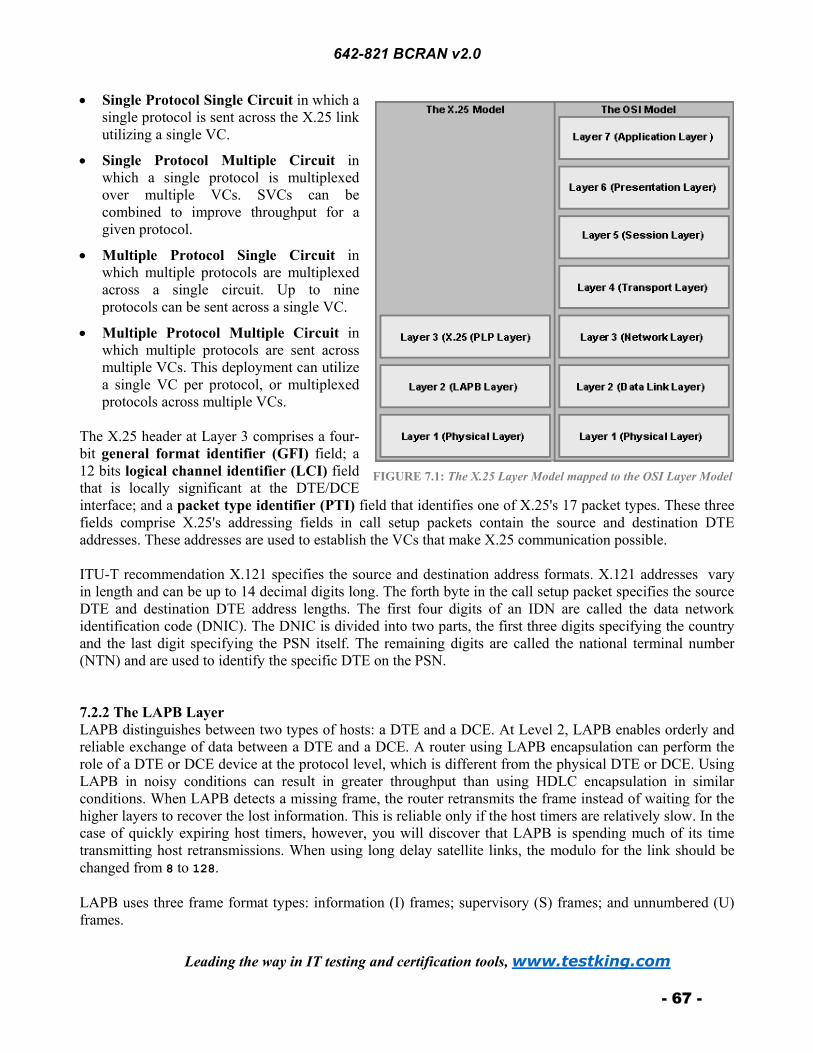
642-821 BCRAN v2.0
Leading the way in IT testing and certification tools, www.testking.com
- 67 -
• Single Protocol Single Circuit in which a single protocol is sent across the X.25 link utilizing a single VC.
• Single Protocol Multiple Circuit in which a single protocol is multiplexed over multiple VCs. SVCs can be combined to improve throughput for a given protocol.
• Multiple Protocol Single Circuit in which multiple protocols are multiplexed across a single circuit. Up to nine protocols can be sent across a single VC.
• Multiple Protocol Multiple Circuit in which multiple protocols are sent across multiple VCs. This deployment can utilize a single VC per protocol, or multiplexed protocols across multiple VCs.
The X.25 header at Layer 3 comprises a four-bit general format identifier (GFI) field; a 12 bits logical channel identifier (LCI) field that is locally significant at the DTE/DCE interface; and a packet type identifier (PTI) field that identifies one of X.25's 17 packet types. These three fields comprise X.25's addressing fields in call setup packets contain the source and destination DTE addresses. These addresses are used to establish the VCs that make X.25 communication possible. ITU-T recommendation X.121 specifies the source and destination address formats. X.121 addresses vary in length and can be up to 14 decimal digits long. The forth byte in the call setup packet specifies the source DTE and destination DTE address lengths. The first four digits of an IDN are called the data network identification code (DNIC). The DNIC is divided into two parts, the first three digits specifying the country and the last digit specifying the PSN itself. The remaining digits are called the national terminal number (NTN) and are used to identify the specific DTE on the PSN. 7.2.2 The LAPB Layer LAPB distinguishes between two types of hosts: a DTE and a DCE. At Level 2, LAPB enables orderly and reliable exchange of data between a DTE and a DCE. A router using LAPB encapsulation can perform the role of a DTE or DCE device at the protocol level, which is different from the physical DTE or DCE. Using LAPB in noisy conditions can result in greater throughput than using HDLC encapsulation in similar conditions. When LAPB detects a missing frame, the router retransmits the frame instead of waiting for the higher layers to recover the lost information. This is reliable only if the host timers are relatively slow. In the case of quickly expiring host timers, however, you will discover that LAPB is spending much of its time transmitting host retransmissions. When using long delay satellite links, the modulo for the link should be changed from 8 to 128. LAPB uses three frame format types: information (I) frames; supervisory (S) frames; and unnumbered (U) frames.
FIGURE 7.1: The X.25 Layer Model mapped to the OSI Layer Model

642-821 BCRAN v2.0
Leading the way in IT testing and certification tools, www.testking.com
- 68 -
• Information (I) frames carry upper-layer information and some control information. Send and receive sequence numbers and the poll final (P/F) bit perform flow control and error recovery. The send sequence number refers to the number of the current frame. The receive sequence number records the number of the frame to be received next. In bidirectional communication, both parties keep send and receive sequence numbers. The poll bit is used to force a final bit message in response, which is used for error detection and recovery.
• Supervisory (S) frames provide control information. They request and suspend transmission, report on status, and acknowledge the receipt of I frames.
• Unnumbered (U) frames are not sequenced and are used for control purposes. 7.2.3 The X.25 Physical Layer X.25 is a WAN technology, so it is implemented on serial interfaces at varying speeds. Physical implementation of any serial-based technology requires the use of a transition cable purchased separately from the router. The cable must be specific to the type of serial interface installed in the router as well as the type of interface on the CSU/DSU. Once the physical cabling is in place, the serial interface can be configured appropriately. 7.3 Configuring X.25 The configuration of X.25 is similar to the configuration of other WAN protocols. It involves the gathering of information that is needed to properly initialize the X.25 interface and enable communication. The actual configuration consists of three steps: setting the encapsulation of the interface and specify DCE or DTE; configuring the X.121 address as assigned by the PDN service provider; and mapping the appropriate next logical hop protocol address to its X.121 address. There are other interface configuration values that can be configured to control the flow of information. These values can be set to specify packet sizes, window sizes, and modulo sizes. The VC ranges and types must also be configured. 7.3.1 Setting the Interface Encapsulation The encapsulation is set at the interface configuration mode prompt using the following command:
encapsulation x25 [ dte | dce ]
If no specification is made, the setting defaults to dte. If the encapsulation is altered from dce to dte, or vice versa, the interface settings are lost and reset to default values. The dce option is used in environments in which the router might be used as a switch. 7.3.2 Configuring the X.121 Address The assignment of X.121 addresses is acquired from the provider. Once the addresses are allocated to you by the service provider, you can use the following syntax to assign it to the proper interface:
x25 address x.121_address
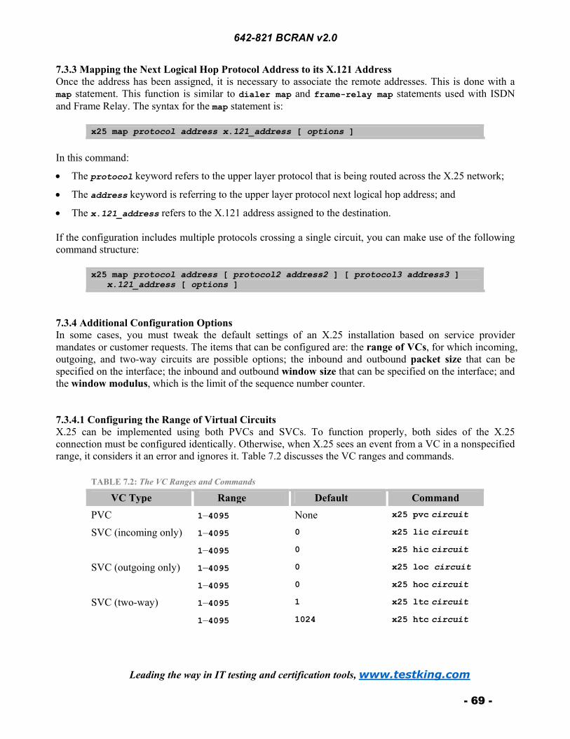
642-821 BCRAN v2.0
Leading the way in IT testing and certification tools, www.testking.com
- 69 -
7.3.3 Mapping the Next Logical Hop Protocol Address to its X.121 Address Once the address has been assigned, it is necessary to associate the remote addresses. This is done with a map statement. This function is similar to dialer map and frame-relay map statements used with ISDN and Frame Relay. The syntax for the map statement is:
x25 map protocol address x.121_address [ options ] In this command:
• The protocol keyword refers to the upper layer protocol that is being routed across the X.25 network;
• The address keyword is referring to the upper layer protocol next logical hop address; and
• The x.121_address refers to the X.121 address assigned to the destination. If the configuration includes multiple protocols crossing a single circuit, you can make use of the following command structure:
x25 map protocol address [ protocol2 address2 ] [ protocol3 address3 ] x.121_address [ options ]
7.3.4 Additional Configuration Options In some cases, you must tweak the default settings of an X.25 installation based on service provider mandates or customer requests. The items that can be configured are: the range of VCs, for which incoming, outgoing, and two-way circuits are possible options; the inbound and outbound packet size that can be specified on the interface; the inbound and outbound window size that can be specified on the interface; and the window modulus, which is the limit of the sequence number counter. 7.3.4.1 Configuring the Range of Virtual Circuits X.25 can be implemented using both PVCs and SVCs. To function properly, both sides of the X.25 connection must be configured identically. Otherwise, when X.25 sees an event from a VC in a nonspecified range, it considers it an error and ignores it. Table 7.2 discusses the VC ranges and commands.
TABLE 7.2: The VC Ranges and Commands
VC Type Range Default Command PVC 1–4095 None x25 pvc circuit
SVC (incoming only) 1–4095 0 x25 lic circuit
1–4095 0 x25 hic circuit
SVC (outgoing only) 1–4095 0 x25 loc circuit
1–4095 0 x25 hoc circuit
SVC (two-way) 1–4095 1 x25 ltc circuit
1–4095 1024 x25 htc circuit
642-821 BCRAN v2.0
Leading the way in IT testing and certification tools, www.testking.com
- 70 -
7.3.4.2 Configuring the Packet Size The maximum inbound and outbound packet sizes can be specified. The default value is 128 bytes; however, the size can be altered. Valid values are 16, 32, 64, 128, 256, 512, 1024, 2048, and 4096 bytes. The command to set the inbound packet size is:
x25 ips packet_size The command to set the outbound packet size is:
x25 ops packet_size The inbound and outbound packet size values should match unless otherwise specified by the carrier. If different, the network must be able to support asymmetric transmission; otherwise, a conflict would occur. 7.3.4.3 Configuring the Window Size The default window size in the X.25 network can also be modified. The default window size is two packets. As with ips and ops, this parameter must be supported by the carrier and must match at both ends to avoid conflict. The range of valid sizes is equal to or 1 less than the modulus size. The command to set the inbound window size is:
x25 win number_of_packets The command to set the outbound window size is:
x25 wout number_of_packets 7.3.4.4 Configuring the Window Modulus The modulus is the packet counting mechanism for X.25. The command to define the counter limit is:
x25 modulo modulus The value specified using the x25 modulo command dictates the number of packets that can be sent before the counter must reset. The default value of 8 enables seven packets to be sent. The only other valid value is 128. A modulo of 128 is rare except in cases involving satellite communications.

642-821 BCRAN v2.0
Leading the way in IT testing and certification tools, www.testking.com
- 71 -
8. Frame Relay Connection Controlling Traffic Flow Frame Relay is a connection-oriented, Layer 2 networking technology. It operates at speeds from 56 kpbs to 45 Mbps. It is very flexible and offers a wide array of deployment options. Frame Relay operates by statistically multiplexing multiple data streams over a single physical link. Each data stream is known as a virtual circuit (VC). Frame Relay VCs come in two types: Permanent Virtual Circuits (PVCs) and Switched Virtual Circuits (SVCs). These PVCs and SVCs are the same as the X.25 PCVs and SVCs that were discussed in Section 7.2.1. Each VC is tagged with an identifier to keep it unique. The identifier, known as a Data Link Connection Identifier (DLCI), is determined on a per-leg basis during the transmission. It must be unique and agreed upon by two adjacent Frame Relay devices. As long as the two agree, the value can be any valid number, and the number does not have to be the same end to end. Valid DLCI numbers are 16-1007. For DLCI purposes, 0-15 and 1008-1023are reserved. The DLCI also defines the logical connection between the Frame Relay (FR) switch and the customer premises equipment (CPE). Frame Relay devices fall into two possible roles, data terminal equipment (DTE) or data circuit-terminating equipment (DCE). The DTE/DCE relationship is a Layer 2 (data link) layer relationship. DTE and DCE relationships are normally electrical. The DTE/DCE relationship at Layer 1 is independent of that at Layer 2.
• DTEs are generally considered to be terminating equipment for a specific network and are located at the customer premises.
• DCEs are carrier-owned internetworking devices. DCE equipment provides clocking and switching services in a network; they are the devices that actually transmit data through the WAN. In most cases, the devices are packet switches.
Local Management Interface (LMI) is the means by which Frame Relay edge devices maintain keepalive messages. The Frame Relay switch is responsible for maintaining the status of the CPE device(s) to which it is attached. LMI is the communication by which the switch monitors status. LMI implements a keepalive mechanism that verifies connectivity between DCE and DTE and the fact that data can flow. A LMI multicast capability, in conjunction with an LMI multicast addressing mechanism, enables attached devices to learn local DLCIs as well as provide global, rather than local, significance to those DLCIs. Finally, LMI provides a status indicator that is constantly exchanged between router and switch. The LMI setting is configurable. There are three supported types of LMI: Cisco LMI, which uses DLCI 1023; ANSI LMI, which is also known as Annex D and uses DLCI 0; and Q933a, which is defined by the ITU and is also known as Annex A. 8.1 Frame Relay Topologies Frame Relay supports connectivity of remote sites through one of three topological strategies. Each has its own advantages and disadvantages.
• Hub and spoke, which is also known as the star topology, is the dominant method of deploying Frame Relay. It consists of a single central office acting as a connection point for all remote offices. Routing between two satellite offices is accomplished through the central office. Routing through the central office tends to be the low-cost solution; however, it is also the least redundant (that is, fault tolerant) strategy.

642-821 BCRAN v2.0
Leading the way in IT testing and certification tools, www.testking.com
- 72 -
• Full mesh, which resemblance to a spider web, has a large number of connections and is very expensive to operate; however, it is the most fault tolerant. Because each site is connected to every other site, the number of connections can be large and expensive. The number of connections that are required is derived through the n(n – 1) ÷ 2 formula, where n is the number of devices you wish to connect.
• Partial mesh, which deploys hub and spoke with redundancy. With this implementation, the cost of full mesh is avoided, and the lack of fault tolerance of hub and spoke is minimized. Although a central office is utilized, redundant connections are installed between critical sites. In essence, it is possible to create a backup central office. This is particularly useful in networks in which delay reductions are necessary because getting to a destination without traversing a central router can decrease delay significantly.
A topology has some affect on the manner in which routers are configured. By default, Frame Relay encapsulated interfaces are multipoint in nature. In environments in which the connection is a single end-to-end PVC with no other connections, there should be no problems. However, in hub and spoke or partial mesh environments, routing update problems can arise. 8.2 Connecting Multiple Sites Through a Single Router Interface When a single physical interface is utilized on a central router to connect multiple remote sites, routing problems arise. These problems are caused by split horizon, which is a rule in routing protocol operation that is designed to eliminate routing loops by not allowing routing updates to be sent out of the interfaces through which they were received. Split horizon shuts down the passing of routing updates regarding networks on the far side of the remote sites. You can resolve split horizon problems through the use of subinterfaces. A subinterface is a logical division of a physical interface (a major interface). The number of subinterfaces that can be placed on a single major interface is limited by the number of Interface Descriptor Blocks (IDBs) available to the router. A logical subinterface should be treated almost the same as a physical interface. It can be configured for multiple protocols, shut down, or anything else common on other interfaces with the exception that you cannot set encapsulation on a subinterface. The configuration of subinterfaces solves the split horizon issue by creating multiple logical interfaces where before existed only one physical interface. Split horizon has no problem with updates leaving through interfaces other than the one through which they were received. Another problem that arises on a single interface servicing multiple VCs is the issue of broadcast traffic. NBMA networks do not enable the propagation of broadcasts through the network. Therefore, the broadcast must be transmitted over each individual VC, i.e., the broadcast goes into a broadcast queue and is sent one time for each circuit being serviced. These broadcasts can consume large amounts of bandwidth in a short time, depending on the volume of broadcast traffic being sent. Based on traffic patterns and utilization of links, you can add additional connections between remote sites and increase the bandwidth available to each site. This can assist in dealing with broadcast traffic as well as other high-volume traffic types. 8.3 Frame Relay Configuration In many cases, the configuration of Frame Relay can be as simple as setting the encapsulation and putting an IP address on the interface. This enables inverse-ARP to dynamically configure the DLCI and discover neighboring routers across the cloud. Although basic functionality can be achieved in this manner, more complex procedures are necessary for hub and spoke subinterface configurations dealing with point-to-multipoint implementations. The configuration of Frame Relay can be accomplished in a four steps, and entails determining the interface to be configured, configuring Frame Relay encapsulation, configuring protocol specific parameters, and configure Frame Relay characteristics.

642-821 BCRAN v2.0
Leading the way in IT testing and certification tools, www.testking.com
- 73 -
8.3.1 Determining the Interface The interface that interfaces the Frame Relay network is the one that should be configured. Once the interface has been selected, you should change to the appropriate interface configuration mode in the router. You should decide whether subinterfaces should be implemented. For a single point-to-point implementation, it might not be necessary to use subinterfaces; however, this implementation does not scale. If future sites are planned, it is best to use subinterfaces from the beginning. To create a subinterface, use the following command to change to the desired interface:
interface interface_type interface_number.subinterface_number For example, to create subinterface 1 on Serial 0, use the command interface serial 0.1. You must also determine the nature, or cast type, of the subinterface to be created, i.e., decide whether the subinterface will act as a point-to-point connection or a point-to-multipoint connection. If not specified, the subinterface defaults to a multipoint connection. To specify the cast type, add the keywords point-to-point or multipoint to the end of the previous command. 8.3.2 Configuring Frame Relay Encapsulation To enable Frame Relay on the interface, issue the encapsulation frame relay command. The encapsulation of the interface determines the way it should act because each encapsulation is technology-specific. The encapsulation specified at this point dictates the Layer 2 framing characteristics of the packet passed to this specific interface from Layer 3. Once the Layer 2 framing is established, the resulting frame can be passed down to the physical layer for transmission. 8.3.3 Configuring Protocol-Specific Parameters For each protocol to be passed across the Frame Relay connection, you must configure appropriate addressing. This addressing must be planned in advance. For point-to-point connections, each individual circuit should have its own subnetwork addressing and two available host addresses. For IP, each subinterface is assigned a separate and unique IP subnet. For IPX, each subinterface must have a unique IPX network number, and so on. As with any other addressing scheme, each side of the link must have a unique host address. For point-to-multipoint connections, each subinterface also must have unique addressing. However, a point-to-multipoint connection can connect to multiple remote sites. Thus, all sites sharing the point-to-multipoint connection are members of the same subnetwork, no matter the number of connections or the protocol. The cast type of the interface also dictates the manner in which DLCIs are assigned to the Frame Relay interface. The next section covers this topic in detail. 8.3.4 Configuring Frame Relay Characteristics You must define specific parameters for Frame Relay operation. The parameters include LMI and DLCI configuration. If you use a pre 11.2 release of IOS Software, you must specify the LMI type that is being implemented. The Frame Relay service provider, or service provider, should provide the LMI information. For IOS Software Release 11.2 and later, you need not configure the LMI type. To disable LMI completely, use the no keepalive command to cease to transmit and receive LMI. However, keepalives must also be disabled at the switch.

642-821 BCRAN v2.0
Leading the way in IT testing and certification tools, www.testking.com
- 74 -
You can now configure address mapping, if necessary. In the case of point-to-point connections, mapping of protocol addresses to DLCIs is dynamic and requires no intervention. However, if point-to-multipoint connections are in use, manual mapping is necessary. Mapping is the same from protocol to protocol and uses the frame-relay map command. The syntax for frame-relay map is:
frame-relay map protocol protocol_address dlci [ broadcast ][ ietf | cisco ]
Protocols supported in the frame-relay map command include IP, IPX, AppleTalk, CLNS, DECnet, XNS, and Vines. The protocol_address in the command is the next hop logical address for the router on the remote end of the connection. The dlci argument represents the local DLCI, not that of the remote end. The broadcast keyword specifies that routing updates traverse the network through this circuit. The final option in the command specifies which Frame Relay implementation to utilize in communications with the remote router. When communicating with a Cisco device on the remote side, the default value (cisco) can be utilized. However, when communicating with non-Cisco gear on the remote end, it can be necessary to specify that the IETF implementation of Frame Relay be used. 8.3.5 Verifying Frame Relay Configuration The most useful method of verifying the Frame Relay configurations is through the use of the show and debug commands. Some of the more useful show and debug commands are:
• show frame-relay pvc is useful for viewing the status of statically or dynamically defined PVCs. The output for each PVC is detailed. The output also gives information on each circuit that specifies the receipt or transmission of FECN/BECN packets. FECN and BECN deal with congestion in the Frame Relay network, so obviously, a low number is preferable. The output also details the number of discard eligible (DE) packets received for which a low number is better.
• show frame-relay lmi allows you to check the status of individual PVCs and to monitor the communication status between the router and the switch. This command show shows the number of LMI messages sent and received across the link between the router and the switch. The LMI type can be specified differently for each interface, so the type is specified in the output. This command also shows the LMI input/output information.
• debug frame-relay lmi is probably the most useful tool in verifying and troubleshooting Frame Relay problems. This command makes it possible to watch the real-time communication between the router and the switch. Each request sent from the router to the switch is noted, and the counter is incremented by 1 with each request. LMIs sent from the switch to the router by the service provider are noted and also are incremented by 1 with each request. As long as both numbers are greater than 0, the router should be functioning normally at Layers 1 and 3.
• show frame-relay map is used to view the DLCI mappings that have been created. They can be static or dynamic and are noted as such in the command output.
8.4 Frame Relay Traffic Shaping Frame Relay traffic shaping is a way of controlling the output of traffic across the Frame Relay network. This can provide granular control of outbound data. Traffic shaping can provide per-VC rate enforcement, BECN support, and queuing at the VC level. Frame Relay traffic shaping is supported only on fast switching and process switching paths. Therefore, to use it, other switching methods must be disabled on all interfaces that send traffic to the serial interface.

642-821 BCRAN v2.0
Leading the way in IT testing and certification tools, www.testking.com
- 75 -
8.4.1 Frame Relay Traffic Parameters Table 8.1 describes the Frame Relay traffic parameters.
TABLE 8.1: Frame Relay Traffic Parameters
Parameter Description cir The average rate you want to transmit. be (Excessive Burst) The amount of excess data allowed to be sent during
the first interval once credit is built up. Transmission credit is built during periods of no transmission.
bc (Committed Burst) The amount of data to send in each tc interval.
tc (Committed Rate Measurement Interval)
The bc ÷ cir time interval. The time interval should not exceed 125 ms.
mincir (Minimum CIR) The minimum amount of data to be sent during periods of congestion. The default is one-half of cir.
PIR (Peak Information Rate) Highest possible rate of transmission on a given interface.
MIR (Minimum Information Rate) Slowest rate of transmission on a given interface. Interval bc ÷ cir. The maximum is 125 ms.
Byte Increment bc ÷ 8. This must be greater than 125.
Limit Byte Increment + be ÷ 8. The parameters are related to Backward Explicit Congestion Notification (BECN) response network congestion. 8.4.2 FECN and BECN Frame Relay's traffic shaping capabilities rely largely on the capability to detect congestion. For this purpose, Forward Explicit Congestion Notification (FECN) and Backward Explicit Congestion Notification (BECN) are implemented. If a Frame Relay switch senses congestion in the network, it sets the FECN bit to 1 in the Frame Relay header for traffic moving toward the destination device. This number indicates a congestive situation. Once received, the destination device flips the BECN bit in return traffic to the source. This informs the source device of the congestion in the network and that it should reduce the transmission rate. Once congestion has been experienced, any traffic moving through the network in violation of the negotiated CIR that has been flagged as Discard Eligible (DE) can be dropped. Retransmission of dropped traffic is left to the Layer 4 protocol, such as TCP, of the end devices. If the router receives BECNs during the current time interval, it decreases the transmission rate by 25 percent. The rate continues to drop with each BECN until the traffic rate reaches the minimum acceptable incoming or outgoing committed information rate (mincir). At this point, the decline in throughput is halted.

642-821 BCRAN v2.0
Leading the way in IT testing and certification tools, www.testking.com
- 76 -
Once the traffic rate has declined involuntarily, it takes 16 time intervals without the receipt of any more BECNs to start to increase traffic flow again. It takes significantly longer to get back up to cir than it did to drop. To shorten the length of time, be can set to a value seven times the value of bc. 8.4.3 Using Frame Relay Traffic Shaping There are a number of instances in which Frame Relay traffic shaping can be useful. If your network consists exclusively of high-bandwidth links, traffic shaping can be beneficial. However, traffic shaping can also be beneficial in mixed bandwidth environments. In addition, any environment in which Voice over Frame Relay is being implemented requires the use of traffic shaping to adequately configure the network for voice traffic. In mixed bandwidth environments, traffic shaping can be utilized to protect the lower-speed links. If traffic shaping is implemented on the faster side, specifically on the VC directing traffic to that specific site, congestion can be stopped before it begins. 8.4.4 Configuring Frame Relay Traffic Shaping Frame Relay traffic shaping is accomplished through the creation of a map class. This map class can be associated with one or more PVCs. The map class defines the traffic parameters for any circuits to which it is applied. The command for defining the map class is:
map-class frame-relay name The name parameter is used to tie the map class to one or more PVCs. Once the map-class command has been entered, the traffic parameters can be defined. The average and peak transmission rates can also be configured at this point along with defining whether the router should respond to BECN requests. It is also possible to define queues to prioritize PVCs. The command for defining peak and average rates is:
frame-relay traffic-rate average [ peak ] The average rate is measured in bps (bps) and should be set to the contracted cir. The peak rate is also measured in bps. Do not use the frame-relay traffic-rate command if you are enabling the adaptive-shaping becn command. Enable a BECN response instead. To specify that the router should respond to BECN requests for throughput reduction, use the frame-relay adaptive-shaping becn command. Use this command over the frame-relay traffic-rate command whenever possible. The frame-relay adaptive-shaping becn command makes the frame-relay becn-response-enable command obsolete. The command for defining the cir for the map class is:
frame-relay cir [ in | out ] bits The rate in the frame-relay cir command is expressed in bps and should be the rate at which transmission should be sent in periods with no congestion. The command for defining the committed burst size for the map class is:
frame-relay bc [ in | out ] bits The bc is the amount to be transmitted per interval and is also specified in bytes.

642-821 BCRAN v2.0
Leading the way in IT testing and certification tools, www.testking.com
- 77 -
The command for defining excessive burst for a map class is:
frame-relay be [ in | out ] bits The be is the additional amount to be sent in the first interval. If cir = port speed, set be to 0 because no additional bandwidth is available for a burst. The command for specify the mincir for the map class is:
frame-relay mincir [ in | out ] bits The mincir is usually one-half the cir. To verify the operation of the Frame Relay traffic shaping configuration, use the show framerelay pvc command. With traffic shaping turned on, all configured parameters are listed. Other useful commands include show traffic-shape and show traffic-shape statistics.

642-821 BCRAN v2.0
Leading the way in IT testing and certification tools, www.testking.com
- 78 -
9. Managing Network Performance with Queuing and Compression 9.1 Queuing The implementation of any queuing strategy results in higher delay in the network. This happens because of a higher per packet processor requirement. Each traffic type must be sorted out and dealt with according to the defined parameters of the queue. This is the trade-off for assuring that your critical traffic passes through the router. Queuing is only necessary when existing traffic flow is having problems getting through the router. If all traffic is going through properly and no packet drops are occurring, then there is no need for queuing. Queuing is most effectively implemented on WAN links. Bursty traffic and low data rates can combine to create a congestive situation that can require administrative oversight to correct. Depending on the maximum transmission units (MTUs) of the surrounding media, queuing is most effective when applied to links with T1 (1.544 Mbps) or E1 (2.048 Mbps) bandwidth speeds or lower. If congestion is temporary, queuing can be a proper remedy to the situation. If the congestion is chronic, queuing can compound the issue by introducing additional delay. At this point, a bandwidth upgrade and possibly a router upgrade is in order. The establishment of a queuing policy assists the network administrator with handling individual traffic types. The goal is to maintain the stability of the overall network. The engineering and design of the network might need to be reevaluated. There are four types of queuing: first in, first out (FIFO); weighted fair queuing (WFQ); priority queuing; and custom queuing. 9.1.1 First In, First Out (FIFO) FIFO is the most basic queuing strategy. It is the first-come, first-served approach to data forwarding. In FIFO, packets are transmitted in the order in which they are received. Until recently, FIFO was the default queuing strategy for all interfaces on a router. However, should it become necessary for the traffic to be reordered in any way, another strategy must be invoked because FIFO gives no regard to one type of traffic over another. It simply dispatches data as it receives it. This, however, is not really queuing; but is more along the lines of buffering. The packets are routed to the interface and stored in router memory until transmittal. The transmission order is based on the arrival order of the first bit of the packet. 9.1.2 Weighted Fair Queuing (WFQ) Weighted Fair Queuing (WFQ) enables Telnet and other interactive traffic to have priority over FTP and other large transfers. This improves overall throughput. The FTP packets get through with relatively little delay, and Telnet users see improved response times. In WFQ, traffic is sorted by high-volume and low-volume communications (sessions). The traffic in a session is kept within one session, and the records are handled FIFO within a particular session. The lower volume interactive traffic is given a priority and flows first. The necessary bandwidth is allocated to the interactive traffic, and the high-volume traffic equally share the remaining bandwidth. WFQ is the default queuing strategy on interfaces of less than 2 MB because at higher speeds, queuing is usually not necessary. In addition, WFQ is on by default for interfaces that support it. WFQ is not used by default on Link Access Procedure on the B channel (LAPB) for X.25, compressed Point-to-Point Protocol (PPP), or Synchronous Data Link Control (SDLC) interfaces.

642-821 BCRAN v2.0
Leading the way in IT testing and certification tools, www.testking.com
- 79 -
Discrimination of traffic conversations is based on source and destination packet header addresses. Other factors such as source and destination MAC addresses, source and destination port or socket numbers, data-link connection identifier (DLCI) in Frame Relay deployments, Quality of Service (QoS) values, and Type of Service (ToS) values also provide discriminatory criteria to the WFQ process. With WFQ, the low-volume traffic is given the priority on the outbound interface. Configuring WFQ involves adjusting the queue limits. To keep some sessions from overwhelming the circuit, you can configure the maximum number of records that any high-volume traffic allows into the queue. The default setting is 64 records, but the supported range is from 1–4096. If a session reaches the queue limit, no further records are queued for that session until the percentage of the entries in the queue for that conversation drops. All new packets for the over-queue-limit conversation are dropped and lost. TCP window sizes control the amount of data that can be transmitted between two hosts without an acknowledgement. A larger window size enables a higher transmission threshold. Sessions using TCP that suffer a packet drop retransmit automatically as part of the Layer 4 flow control process. As a consequence, the communicating parties in the TCP conversation are forced to reduce their window sizes. The fair-queue command is shown below:
fair-queue [ queue_limit ] WFQ can be disabled using the no fair-queue command. 9.1.3 Priority Queuing When absolute control over the throughput is necessary, priority queuing should be utilized. Priority queuing gives the network administrator granular control that reduces network delay for high-priority traffic. Variations of priority queuing have been in use for a number of years in differing vendor implementations. Cisco's implementation of priority queuing utilizes four queues: high, medium, normal, and low. For traffic placed in individual queues, the output strategy is FIFO. The traffic defined as high priority receives the benefit of all available resources on the output interface until the queue is empty. Once the high queue is complete, the medium queue traffic is dispatched in the same manner until empty. At this stage, the high queue is again checked for content and emptied if there is any new traffic. If there are no entries in the high queue after servicing the medium queue, the normal queue is emptied. Once normal traffic has been dispatched, the high queue is checked again, followed by the medium and normal queues. If all three are empty, the low queue is serviced. The result is that high-priority traffic always suffers the shortest delay in awaiting dispatch. The low-priority traffic must wait until it can be serviced. The traffic can even age out and be purged from memory if the queue overflows. Once an overflow occurs, all new packets for that queue are dropped until space is freed up in the queue. Each queue has a fixed length, which is configurable. The defaults are 20 records for high, 40 records for medium, 60 records for normal, and 80 records for low. The lower priority queues are larger, by default, than the higher priority queues to accommodate the queuing algorithm and the fact that the lower priority queues might wait longer to be serviced. The configuration of priority queuing, in the most basic of configurations, entails configuring each protocol that traverses a particular WAN link to enter a specific queue. In more advanced configurations, standard or extended access lists can be defined for specific traffic types and applied to a queue configuration. In priority queuing, the priority-list commands are read in the order of their appearance until a matching protocol or interface type is found. When a match is found, the packet is assigned to the appropriate queue and the search ends. Therefore some planning needs to go into the creation of the list. The configuration of

642-821 BCRAN v2.0
Leading the way in IT testing and certification tools, www.testking.com
- 80 -
priority queuing entails defining specific access lists if they are to be used; creating the priority list; applying the priority list to the interface; and verifying the queuing process.
• If it is necessary to queue traffic based on a specific network address, protocol, or application, access lists can be put in place to sort the traffic. Standard or extended access lists can be defined to specify the traffic type or types that should be placed into a specific queue.
• The command parameters for priority queue configuration for a specific protocol or traffic type is:
priority-list list_number protocol protocol { high | medium | normal | low } queue_keyword keyword_value
The list_number argument can be an arbitrarily selected number from 1–16; however, all lines for a particular priority list must have the same list_number to function properly. The queue_keyword and keyword_value parameters are used to associate access lists with the priority list.
• Once the priority list is created, it must be associated with an interface. The priority list is activated on the interface by the priority-group command.
• Verifying the queuing configuration can be performed by using the show queueing command, which shows the detail of the priority lists configured on the router and the appropriate details of each list.
Note: The command used to verify the queuing configuration is show
queueing and not show queuing. The latter command is not recognized by the Cisco IOS.
9.1.4 Custom Queuing Custom queuing enables the sharing of available bandwidth across all types of traffic. This technique allocates a percentage of bandwidth to each of the various traffic types. The difference between this approach and priority queuing is that the queues are processed in round-robin sequence. Therefore, it is possible that high priority traffic would not be serviced quickly enough because although each type of traffic would get some bandwidth, no traffic would be designated with a higher priority than the rest. Custom queuing employs 17 queues with queue 0, which the system queue, being used for the system. The remaining 16 queues can be configured by the administrator. By default, queues evenly balance traffic. There are two thresholds by which queues are measured: queue limit and byte count. The queue limit default is 20 records. The byte count limit default is 1500 bytes. Whichever limit is reached first signifies the end of a particular queue's time with the processor. If the byte count limit is reached during the transmission of a packet, the entire packet is dispatched. As with priority queuing, the configuration of custom queuing involves the creation of a list and associating a group with an interface. Traffic in the queues can be configured based on a specific traffic type, protocol, or input interface. Access lists can be configured to place specific traffic types into a particular queue, and traffic not designated to a particular queue can be placed in a default queue.
Note: To implement custom queuing on a Frame Relay interface, Frame Relay traffic shaping must be disabled.

642-821 BCRAN v2.0
Leading the way in IT testing and certification tools, www.testking.com
- 81 -
• If it is necessary to queue traffic based on a specific network address, protocol, or application, access lists can be put in place to sort the traffic. Standard or extended access lists can be defined to specify the traffic type or types that should be placed into a specific queue.
• The command parameters for custom queue configuration is:
queue-list list_number protocol protocol queue_number queue_keyword keyword_value
The list_number argument can be an arbitrarily selected number from 1–16; however, all lines for a particular queue list must have the same list_number to function properly. The queue_keyword and keyword_value parameters are used to associate access lists with the queue list. It is also possible to specify that any traffic that entered the router through a particular interface be placed into a particular queue, using the following command:
queue-list list_number interface interface_type interface_number queue_number
Any traffic that does not match any lines in a priority list is placed in the default queue. For custom queuing, the default queue is queue 1. The command for assigning a default queue is:
queue-list list_number default queue_number
The amount of data a queue can service before having to move on to the next queue is known as a service threshold. You can alter the service threshold of each individual queue. The command for resizing a queue's record limit service threshold is:
queue-list list_number queue queue_number limit limit_number
Valid entries for this command are 0–32, 767.
The command structure for altering the byte-count service threshold is as follows:
queue-list list_number queue queue_number byte-count byte_count_number
• Once the queue list is created, it must be associated with an interface. The queue list is activated on the interface by the custom-queue-list command.
• Verifying the queuing configuration can be performed by using the show queueing command, which shows the detail of the priority lists configured on the router and the appropriate details of each list.
Note: The command used to verify the queuing configuration is show
queueing and not show queuing. The latter command is not recognized by the Cisco IOS.

642-821 BCRAN v2.0
Leading the way in IT testing and certification tools, www.testking.com
- 82 -
9.2 Compression There are compression methods for data, links, hard drives, etc, as well as compression across WAN links. Whether data is already compressed when WAN links begin to process it affects the router's capability to further compress that data. If data is already compressed, recompressing can make the data larger. Compression, like queuing, is meant to provide critical time to plan and deploy network upgrades and to reduce overall utilization of a WAN link. However, the execution of the compression algorithm adds a significant amount of cycles to the CPU and CPU utilization of the router can increase considerably while the WAN link utilization drops considerably. The effects of compression must be taken into account prior to implementation. If your routers are already at 80 percent or more CPU utilization, you should not implement compression. Data compression makes efficient use of bandwidth and increases WAN throughput by reducing the size of the frame being transported. Compression is best utilized on slower WAN links. The compression types that Cisco supports are: link compression, payload compression, TCP Header compression, and Microsoft Point-to-Point compression. 9.2.1 Link Compression Link compression, which is also known as per-interface compression, is the compression of the entire transported entity, i.e., it compresses the header and the payload. Link compression is not dependent on any particular protocol function. Cisco supports two algorithms on its router chassis to compress traffic: STAC and Predictor. For HDLC links, STAC is the only available choice. For data transmission over point-to-point dedicated connections, use link compression. In link compression, the complete packet is compressed and any header information specific to WAN switching technologies is not available to the network. 9.2.1.1 STAC A company known as STAC Electronics provides the STAC compression algorithm, also known as stacker, for Cisco routers. STAC is based on an algorithm known as Lempel-Ziv (LZ), which searches the data stream for redundant strings and replaces them with a token. The token is an information pointer that is significantly shorter than the string it replaces. If LZ cannot find any duplicated strings in the data, no compression occurs and transmission occurs as if the link had no compression activated. There are cases, such as the sending of encrypted data, in which compression actually expands the size of a transmission. In such cases, the original transmission is sent untouched. The STAC compression algorithm tends to be quite CPU-intensive and should not be implemented on routers with an already high CPU utilization. 9.2.1.2 Predictor The Predictor compression is a Cisco-proprietary algorithm that attempts to predict the coming character sequences by an implementing and indexing system that is based on a compression dictionary. If a character string can be found that matches an entry in the dictionary, the string is replaced with the entry from the dictionary. That entry comprises a much shorter sequence of characters. At the remote end, the characters are compared to the data dictionary once again to be decoded. While STAC is CPU-intensive, Predictor tends to be extremely memory intensive. Therefore, if the router has not been outfitted with a good amount of RAM, do not even think about implementing Predictor. If RAM is plentiful, it is a consideration that can be beneficial.

642-821 BCRAN v2.0
Leading the way in IT testing and certification tools, www.testking.com
- 83 -
9.2.2 Payload Compression Payload compression is also known as per-VC compression and compresses only the data portion of the transmission. All headers are left intact. It cannot be assumed that customer WAN links are all dedicated point-to-point connections. To that end, payload compression might need to be implemented if compression is needed on a WAN link. WAN technologies such as Frame Relay, ATM, X.25, and SMDS require that the header information be untouched so that it can be read by the individual switches that the transmission crosses. Any implementation of virtual circuits disallows link compression. In these cases, payload compression is appropriate. 9.2.3 TCP Header Compression RFC 1144 defines the algorithm for TCP/IP header compression. The 20-byte IP header is compressed to 2 or 4 bytes to reduce overhead across the network. The Layer 2 header remains intact so that it can be utilized by the appropriate Layer 2 transport. This type of compression is most beneficial when used with implementations transmitting small packets, such as voice over IP, Telnet, and so forth. This type of compression can be done on just about any WAN implementation. 9.3 Compression Issues Specific issues arise during specific network implementations. In selecting the algorithm that will be utilized for a particular deployment, you should consider:
• Some modems that capable of implementing compression are not necessarily compatible. For example, modems making use of MNP5 and V.42bis are not compatible. If compression is being performed by the modem, you should not configure compression at the router level.
• Encryption occurs at the network layer where compression is a Layer 2 function. Encryption is a security feature. Encryption requires the removal of anything that looks like a pattern. Thus, when LZ tries to run, there are no redundant strings for it to replace with a token. Therefore, the compression is unsuccessful and can actually expand the traffic it was attempting to compress. In such a case, the traffic is sent uncompressed. If you do not want to send traffic uncompressed, you can implement compression and encryption at Layer 3 using the IP Compression Protocol (Icomputeromp) and IP Security Protocol (IPSec), respectively.
• Some algorithms are memory-intensive while others are CPUintensive. Thus, before planning or implementing compression, you must know the physical configuration of your router.
9.4 Configuring Compression There are a number of commands used to configure compression. Most of these commands are technology-specific. For software compression, the following command is used:
compress [ predictor | stac | mppc ]
For Frame Relay deployments, the following command is used to enable STAC compression on an interface or a subinterface:
frame-relay payload-compress
For X.25 deployments, the following command is used to enable TCP header compression:

642-821 BCRAN v2.0
Leading the way in IT testing and certification tools, www.testking.com
- 84 -
ip tcp header-compression [ passive ]
The passive keyword in this command specifies that compression be performed only if packets received on that interface are compressed on arrival.

642-821 BCRAN v2.0
Leading the way in IT testing and certification tools, www.testking.com
- 85 -
10. Scaling IP Addresses with NAT The original design for the Internet required every organization to have one or more unique IP network numbers. In the early to mid-1990s, it became apparent that the Internet was growing so fast that all IP network numbers would be used. One solution to this problem was to increase the size of the IP address by developing IP Version 6 (IPv6). IPv6 has a much larger address structure than IPv4, allowing for trillions of IPv6 networks. Three other IP functions have been introduced to reduce the need for IPv4 registered network numbers. These include Network Address Translation (NAT), along with a feature called private IP addressing, which allows organizations to use unregistered IP network numbers internally and still communicate well with the Internet; and Classless Interdomain Routing (CIDR), which allows Internet service providers (ISPs) to reduce the wasting of IP addresses by assigning a company a subset of a network number rather than the entire network. Most organizations have a number of computers that will never be connected to the Internet. These computers do not need globally unique IP addresses but must be unique within the organization’s network. Thus, an organization could use any network number(s) it wanted, regardless of whether those network number(s) are in use on the Internet or not. However, a set of IP addresses from Class A, Class B and Class C has been set aside for use in private networks and has been defined in RFC 1918. This RFC defines a set of networks that not be assigned to any organization as a registered network number to be used on the Internet. These network numbers allow organizations to use unregistered network numbers that are not used by anyone else in the public Internet. However, no organization is allowed to advertise these networks using a routing protocol on the Internet.
TABLE 10.1: The Private IP Address Space defined by RFC 1918 Range of IP Addresses Number of Networks Class
10.0.0.0 to 10.255.255.255 1 A 172.16.0.0 to 172.31.255.255 16 B 192.168.0.0 to 192.168.255.255 256 C
10.1 Characteristics of NAT NAT, which is defined in RFC 1631, enables nonregistered IP addresses to be used inside a private network and to gain access to a public network, such as the World Wide Web. The edge router connected to the public network uses NAT to translate the private network addresses to a registered public address. The translation can be statically or dynamically done. In the case of a simple translation, each nonregistered IP address is translated to a unique public address. This enables access from networks that are using nonregistered addressing (or a private address space) to the WWW. In this scenario, the administrator would first have to find an Internet service provider (ISP) to supply a block of addresses for use. This may be monetarily difficult for all but the largest of companies. To conserve the use of address space, a private space can be overloaded to a single or small number of addresses by using the source IP address plus the source port of the packet to further distinguish the sending address. Overloading uses the source port to further distinguish which sending station is transmitting. In this way, a single legitimate IP address can be used for many senders. The source port is a number greater than 1024 and is a software addressable port at the transport layer. The first 1024 port numbers are well-known

642-821 BCRAN v2.0
Leading the way in IT testing and certification tools, www.testking.com
- 86 -
ports, which are assigned by RFC 1400. The overloading feature of NAT uses the entire socket to track the sender; thus, the same IP address can be substituted for many sending addresses. Another use of NAT occurs when two networks are overlapped, or using the same numbering scheme. If they are merged, the IP address scheme fails because of the overlap. This NAT function is not something that should be designed into a network. NAT overlap aids the administrator when a merger occurs. The two entities, without the renumbering of each end station, can be consolidated. In this way, the administrator can focus on putting a renumbering plan in place. Overlapping networks can occur for a number of reasons, such as a merger, the consolidation of company resources that are tied with newly installed WAN components, etc. You can merge two companies using the same private address space by using the NAT overlapping network feature; essentially, each network is translated to the other. This double translation can take place on a single router. Another area in which overlapping can occur is when a company elects to use a nonprivate address for their own purposes with the idea that they will never connect to the Internet. This is bad practice in today's e-commerce driven world. NAT can be used for TCP load distribution. Load distribution takes advantage of the NAT function by allowing a site to advertise an address but when you send a packet to the advertised address, it is rerouted to another set of addresses. Load distribution occurs, for example, when a large hardware company has multiple mirrored servers on their internal web site and has advertised through DNS that to access their server. As a request comes in, it would be sent in a rotary or round-robin fashion to each of the mirrored servers. Cisco offers the Local Director software product, which can accomplish the same load distribution, but in a much more resilient fashion. The disadvantages to NAT implementation are:
• An increased latency due to the introduction of a translation step in the switching path.
• A lack of accountability as it is not possible to determine which internal IP address is responsible for traffic.
• Some applications that require a specific source port or source address would not be able to function in a NAT environment that provides randomly selected address and port assignments.
10.2 Variations of NAT The Cisco IOS software supports several variations of NAT. These include Static NAT; Dynamic NAT; and Overloading NAT with Port Address Translation (PAT). 10.2.1 Static NAT In Static NAT, the IP addresses are statically mapped to each other. Thus, the NAT router simply configures a one-to-one mapping between the private address and the registered address that is used on its behalf. Supporting two IP hosts in the private network requires a second static one-to-one mapping using a second IP address in the public address range, depending on the
Cisco Terminology
The addresses used for NAT translation can be summed up in four categories: Inside Local, which are the IP addresses that are unique to the host inside the network, but not globally significant. Inside Global, which are the IP addresses that are assigned by the IANA or service provider. They are legitimate in the global address space or Internet. The Inside Local addresses are translated to the Inside Global address for Internet use. Outside Local, which are the IP addresses of a host on an outside network that is presented to the inside network and that is legitimate to the local network. These addresses do not have to be globally significant. Outside Global, which are the IP addresses that are globally routable on the Internet space.

642-821 BCRAN v2.0
Leading the way in IT testing and certification tools, www.testking.com
- 87 -
number of addresses supported by the registered IP address. 10.2.2 Dynamic NAT Dynamic NAT is similar to static NAT in that the NAT router creates a one-to-one mapping between an inside local and inside global address and changes the IP addresses in packets as they exit and enter the inside network. However, the mapping of an inside local address to an inside global address happens dynamically. Dynamic NAT accomplishes this by setting up a pool of possible inside global addresses and defining criteria for the set of inside local IP addresses whose traffic should be translated with NAT. With dynamic NAT, you can configure the NAT router with more IP addresses in the inside local address list than in the inside global address pool. When the number of registered public IP addresses is defined in the inside global address pool, the router allocates addresses from the pool until all are allocated. If a new packet arrives, and it needs a NAT entry, but all the pooled IP addresses are already allocated, the router discards the packet. The user must try again until a NAT entry times out, at which point the NAT function works for the next host that sends a packet. This can be overcome through the use of Port Address Translation (PAT). 10.2.3 Overloading NAT with Port Address Translation (PAT) In some networks, most, if not all, IP hosts need to reach the Internet. If that network uses private IP addresses, the NAT router needs a very large set of registered IP addresses. If you use static NAT, each private IP host that needs Internet access needs a publicly registered IP address. Dynamic NAT lessens the problem, but if a large percentage of the IP hosts in the network need Internet access throughout normal business hours, a large number of registered IP addresses would also be required. These problems can be overcome through overloading with port address translation. Overloading allows NAT to scale to support many clients with only a few public IP addresses. To support lots of inside local IP addresses with only a few inside global, publicly registered IP addresses, NAT overload uses Port Address Translation (PAT), translating the IP address as well as translating the port number. When NAT creates the dynamic mapping, it selects not only an inside global IP address but also a unique port number to use with that address. The NAT router keeps a NAT table entry for every unique combination of inside local IP address and port, with translation to the inside global address and a unique port number associated with the inside global address. And because the port number field has 16 bits, NAT overload can use more than 65,000 port numbers, allowing it to scale well without needing many registered IP addresses. 10.2.4 Translating Overlapping Addresses NAT can also be used in organizations that do not use private addressing but use a network number registered to another company. If one organization uses a network number that is registered to another organization, and both organizations are connected to the Internet, NAT can be used to translate both the source and the destination IP addresses. However, both the source and the destination addresses must be changed as the packet passes through the NAT router.

642-821 BCRAN v2.0
Leading the way in IT testing and certification tools, www.testking.com
- 88 -
10.3 Configuring NAT There are five general configurations that are used for NAT. These are: simple, static, overload, overlap, and load distribution. In all cases, the general syntax is essentially the same though the arguments that are added indicate which configuration is being used. 10.3.1 Configuring Simple Dynamic NAT The simplest form of configuration is a one-to-one translation in which the IP address of the Inside Local address in the network header is replaced by an Inside Global address. The replacement can be done statically or dynamically. The two key commands here are ip nat pool and ip nat inside. 10.3.2 Static NAT Configuration It is possible to configure NAT statically. Static translation is done using the following command:
ip nat inside source static
10.3.3 Configuring NAT Overloading To convert the configuration for simple NAT translation to overload, the administrator must use the overload argument. Overloading an Inside Global address uses the same syntax as the simple NAT translation, but with the extra argument, the router knows to track the port numbers for the translation table. 10.3.4 Configuring NAT Overlapping The following configuration uses the addresses designated as Outside Global and Outside Local with reference, albeit arbitrary, to one or the other networks. One network is declared as the inside space and one is declared as the outside space. The key is which pool is used. For those source addresses that arrive on an outside interface and that are destined for an inside interface, the translation uses the pool called coming-in. The source addresses that arrive on an inside interface destined for the outside interface use the pool called going-out. The access list that dictates which addresses are matched and must use the designated pool is the same for both. 10.3.5 Configuring NAT TCP Load Distribution NAT TCP load balancing configuration is straightforward. Any packet that arrives at a company's Internet route is translated in a rotary fashion to one of the mirrored servers. The declaration statement for the translation specifies that the destination address should be checked against the list and not the source. In addition, the argument rotary is placed at the end of the declaration. In this way, each incoming packet is translated to one of the pool members in a recurring sequential fashion; thus, a load distribution is achieved over the four servers. 10.3.6 Verification of NAT Translation There are two commands to verify and troubleshoot the NAT configuration: show ip nat translation and show ip nat statistics. The translation table is the same format for simple, overload, overlapped, and load distribution. The information provided is different depending upon the configuration.

642-821 BCRAN v2.0
Leading the way in IT testing and certification tools, www.testking.com
- 89 -
The show ip nat statistics command displays which interfaces are inside and which are outside, the pool name, and the addresses that are with the mask. The hits and misses refer to the number of times a translation lookup succeeded or failed. To troubleshoot NAT, you can use the debug ip nat command. The output from this command shows which addresses were translated and, for a TCP connection, what the transaction numbers are. 10.4 Port Address Translation (PAT) As mentioned in Section 10.2.3, PAT is a form of NAT in which the port is also replaced at the translating device. PAT is the only address translation feature for the Cisco 700 series router. The concept behind PAT is the same as for NAT. A pool of addresses is not needed because only one address services all devices. The two commands that are needed for the 700 to use PAT are:
set ip pat on
and
set ip pat porthandler port ip_address { default | telnet | ftp | smtp | wins | http | off }
In the latter command, port is the transport layer port for the application and ip_address is the local address of the device. Once you enter the set ip pat on command, the single address that is used for the translation is included in the port handler assignment. The port handler is unique to the 700 series router. The port handler declares which ports are translated. Turning PAT on is a system-wide command to the 700 series router. The definition for the porthandler function is done within a profile. There are a number of limitations that must be addressed while using this technology: ping from an outside host ends at the router, therefore, end-to-end connectivity testing is not possible; only one inside web server, FTP server, Telnet server, etc is supported because all port traffic is defined by a single ip porthandler command; and only 15 port handlers are supported in a single configuration. In addition, only 400 PAT entries are allocated for sharing among the inside machines; only 15 port handler addresses can be used; and 1500 maximum MAC addresses can be supported

642-821 BCRAN v2.0
Leading the way in IT testing and certification tools, www.testking.com
- 90 -
11. Using AAA to Scale Access Control in an Expanding Network AAA provides a method for setting up access control on a router. Access control provides a means to declare authentication, authorization, and tracking or accounting.
• Authentication identifies users. During the authentication process, the user name and password are checked against the AAA database. Authentication determines who the user is. Passing the authentication test enables access to the network. This process is only one of the components for user control with AAA. Once the userid and password are accepted, AAA can be used to define what the user is then authorized to do.
• Authorization enables the administrator to control authorization on a one-time, per-service, peruser list, per-group, or per-protocol basis. AAA lets the administrator create attributes that describe the functions that the user is allowed to use. AAA authorization works by assembling a set of attributes that describe what the user is authorized to perform. These attributes are compared to the information contained in a database for a given user and the result is returned to AAA to determine the user's actual capabilities and restrictions. This requires that the database be in constant communication with the AAA server during the connection to the RAS device.
• Accounting enables the administrator to collect information such as start and stop times for user access, executed commands, traffic statistics, and resource usage and then store that information in the RDBMS. In other words, accounting enables the tracking of service and resources that are "consumed" by the user. The key point to accounting is the capability of the administrator to proactively track and predict service and resource usage. This information can then be used for client billing, internal billing, network management, or audit trails.
CiscoSecure ACS (Access Control Server) provides authentication, authorization, and accounting and is used in many of the BCRAN classes as the AAA server. This does not mean that CiscoSecure is the only AAA server. CiscoSecure is only one of the AAA server software packages that are available. CiscoSecure comes bundled with:
• AAA Server, which is the basic AAA functionality for authentication, authorization, and accounting.
• Netscape Fastrack Server, which provides an interface function to the GUI Admin Client. Admin Client enables the administrator to manage the CiscoSecure ACS database through Netscape or Internet Explorer. The Web-based interface enables logins to the ACS database to perform system administrator tasks. ACS stores these modifications in its relational database management system (RDBMS).
• The ACS server can operate with an external RDBMS or the Oracle and Sybase Enterprise database applications because it uses the open database connectivity (ODBC) interface. The RDBMS that is bundled with the CiscoSecure package is SQLAnywhere and is a nonscalable RDBMS.
11.1 Interface Types An understanding of the communication method on each port or port definition is important to understanding and performing a successful configuration of AAA. Character mode is used on the TTY, VTY, AUX, and CON ports. These are the control ports on the router. Packet mode is used on the async, group-async, BRI, PRI, serial, dialer profiles, and dialer rotaries. These are the communication ports on the router. The concept of control versus communication is a fine distinction. The use of the term control indicates a character communication connection that enables control or configuration of the router. The term
642-821 BCRAN v2.0
Leading the way in IT testing and certification tools, www.testking.com
- 91 -
communication indicates that the port is being used to access another source other than the router. Control ports are ports in which router configuration would normally take place. Character mode sends keystrokes to the router through the TTY, VTY, AUX and CON ports for configuration or query commands. Communication ports are ports in which communication to another device occurs or where traffic is passing through the router to another device. These ports are WAN ports. Packet mode uses interface mode or a link protocol session to communicate with a device other than the router. The defined interfaces on the router are async, group-async, BRI, PRI, serial, dialer profiles, and dialer rotaries. Interfaces become important to the configuration of AAA. Each of the authentications and authorizations is tied to one of the interfaces. 11.2 AAA Configuration The configuration of AAA entails enabling of AAA Configuration on the router; defining authentication, authorization, and accounting; and enabling or defining the method on the interface. 11.2.1 Enabling AAA Use the following command to enable AAA on the routers:
aaa new-model
The no form of this command disables AAA on the router. Once AAA is enabled, the router must point to the source of the AAA server. For a TACACS, the command is:
tacacs-server host ip_address [ single-connection ] The ip_address parameter designates the location of the CiscoSecure server or another TACACS server. The optional single-connection parameter tells the router to maintain a single connection for the duration of the session between the router and the AAA device. The alternative, which is the default, is to open and close a TCP connection for each session. Cisco recommends the single-connection feature for improved performance. A shared password is used between the access router and the AAA server for security. The command to establish this password on the router is:
tacacs-server key password The password must also be configured on the AAA server and is case-sensitive. The first steps for the configuration of AAA used on a RADIUS server are similar to the TACACS implementation: "tacacs" is replaced by "radius" as shown below:
aaa new-model radius-server host ip_address [ single-connection ] radius-server key password

642-821 BCRAN v2.0
Leading the way in IT testing and certification tools, www.testking.com
- 92 -
11.2.2 AAA Authentication Once AAA has been enabled on the router, the administrator must declare the methods by which authentication can take place. The key issue is to ensure that the administrator has a way to gain access to the router if the AAA server is down. Failure to provide a backdoor interface can result in lost communications to the router and the necessity to break in through the console port. Care should be taken to always configure a local access method during any implementation of AAA. The global configuration commands enable the administrator to declare the method that is used for authentication, regardless of the access mode being used. These methods include enable, line, local, and none, and are checked in the order in which they are specified in the command. The generic form for the authentication command is:
aaa authentication [ login | enable | arap | ppp | nasi ] method Each command in the following list can stand alone and each declares a command definition for the authentication command. In addition, each command is used for a specific access purpose.
aaa authentication login [ default | listname ]
The declaration of default tells the router what to do if no listname has been declared on the interface. If a listname has been declared, that listname controls the login. The following global command declares how the list_name is interpreted:
aaa authentication login list_name argument argument argument ... On each interface that is declared to use authentication list_name, one or more of the following arguments is used for the authentication:
[ enable | line | local | none | tacacs+ | radius | guest ]
Table 11.1 describes the methods for login authentication.
TABLE 11.1: Methods for AAA Login Authentication
Method Description line This method says to use the password that is on the line that is being
attached to. This is done using the line command login and the command password password, where password is the password for the line.
enable This method says to use the enable password for authentication on the interface. The authentication is compared against the enable password on the router.
local This method says to use the username user_name password password pairs that are on the router for authentication.
none This method says to not use an authentication method.

642-821 BCRAN v2.0
Leading the way in IT testing and certification tools, www.testking.com
- 93 -
tacacs+ This method says to use the TACACS server declared by the tacacs-server host ip_address statement on the router.
radius This method says to use the RADIUS server declared by the radius-server host ip_address statement on the router.
If no AAA methods are set for a user tries to access privileged mode on the router, the user must have the password. This password is demanded by the IOS. If AAA is being used and no default is set, the user also needs the password for access to the privileged mode. The following line command is used to declare that a user can gain access to privilege mode:
aaa authentication enable list_name argument argument argument ... One or more of the following arguments is used with the authentication enable command:
[ enable | line | local | none | tacacs+ | radius | guest ]
Table 11.2 describes the methods for enabling authentication.
TABLE 11.2: Methods for Enabling AAA Authentication
Method Description enable This method says to use the enable password for authentication on the
interface. The authentication is compared against the enable password on the router.
line This method says to use the password that is on the line that is being attached to. This is done using the line command login and the command password password, where password is the password for the line.
none This method says to not use an authentication method. tacacs+ This method says to use the TACACS server declared by the tacacs-
server host ip_address statement on the router. radius This method says to use the RADIUS server declared by the radius-
server host ip_address statement on the router. The aaa authentication arap command is used in conjunction with the arap authentication line configuration command. This describes the methods that are tried when AppleTalk Remote Access (ARA) users attempt to gain access to the router. Table 11.3 describes the methods for authentication using AAA for ARAP.
TABLE 11.3: Methods for Authentication using AAA for ARAP
Method Description line This method says to use the password that is on the line that is being
attached to. This is done using the line command login and the command password password, where password is the password for

642-821 BCRAN v2.0
Leading the way in IT testing and certification tools, www.testking.com
- 94 -
the line. local This method says to use the username user_name password password
pairs that are on the router for authentication. tacacs+ This method says to use the TACACS server declared by the tacacs-
server host ip_address statement on the router. guest This method says to allow a login if the username is guest. This option
is only valid using ARAP. auth-guest This method says to allow the guest login only if the user has already
logged into the EXEC process on the router and has now started the ARAP process.
By default, guest logins through ARAP are disabled when AAA is initialized. The aaa authentication arap command with either the guest or auth-guest keyword is then required for guest access. The aaa authentication ppp command is used in conjunction with the ppp authentication line configuration command to describe the methods that are tried when point-to-point (PPP) users attempt to gain access to the router. With the ppp command, set the interface command is ppp authentication options, where the options are the standard non-AAA options of pap, chap, pap chap, chap pap, or ms-chap. The AAA command methods can also be used. Table 11.4 describes the methods for authentication using AAA for PPP.
TABLE 11.4: Methods for Authentication using AAA for PPP
Method Description local This method says to use the username user_name password password
pairs that are on the router for authentication. none This method says to not use an authentication method. tacacs+ This method says to use the TACACS server declared by the tacacs-
server host ip_address statement on the router. radius This method says to use the RADIUS server declared by the radius-
server host ip_address statement on the router. krb5 This method says that the Kerberos 5 method is available only for PPP
operations, and communications with a Kerberos security server must be established. Kerberos login authentication works with PPP Password Authentication Protocol (PAP) only.
if-needed This method says to ignore the authentication process if the user has been authenticated previously on the TTY line.
The aaa authentication nasi command is used with the nasi authentication line configuration command to specify a list of authentication methods that are tried when a NASI user attempts to gain access to the router. Table 11.5 describes the methods for authentication using AAA for NASI.

642-821 BCRAN v2.0
Leading the way in IT testing and certification tools, www.testking.com
- 95 -
TABLE 11.5: Methods for Authentication using AAA for NASI
Method Description line This method says to use the password that is on the line that is being
attached to. This is done using the line command login and the command password password, where password is the password for the line.
enable This method says to use the enable password for authentication on the interface. The authentication is compared against the enable password on the router.
local This method says to use the username user_name password password pairs that are on the router for authentication.
none This method says to not use an authentication method. tacacs+ This method says to use the TACACS server declared by the tacacs-
server host ip_address statement on the router. 11.2.3 AAA Authorization Once a user has been authenticated, he or she can be further restricted in what he or she is allowed to do. This is done. These restrictions can be applied to activities or services offered on the router and is achieved by using the aaa authorization command. This command takes on two arguments: an authorization area method as is shown below:
aaa authorization { authorization } { method } The authorization can be:
• network for authorization to perform all network-related service requests;
• exec for authorization to determine if the user is allowed to create and run the router EXEC shell;
• command level for authorization of all commands at the specified privilege level. The level can be set to values of 1–15; and
• reverse-access for authorization of reverse access connections such as reverse Telnet. The method used for determining the authorization of the authenticated user can be:
• tacacs+, which states that TACACS+ authorization be used. TACACS+ authorization is done by associating attributevalue (AV) pairs to individual users. The AV pair associates a function that the user is authorized to do.
• if-authenticated, which states that if the user has been authenticated, he or she is allowed to perform the function.
• none, which states that authorization information is nor required.
• local, which states that the router or access server consults its local database, as defined by the use of the username/password pairs that are configured in global configuration mode on the router.

642-821 BCRAN v2.0
Leading the way in IT testing and certification tools, www.testking.com
- 96 -
• radius, which states that RADIUS authorization be used. RADIUS authorization is done by associating attributes to a username on the RADIUS server. Each username and the associated attributes are stored within the RADIUS database.
• krb5-instance, which states that the router must query the Kerberos server for authorization as the authorizations are stored on the Kerberos server.
11.2.4 AAA Accounting AAA accounting can supply information concerning user activity back to the database. In addition, accounting can be used to track resource usage to better allocate system usage. Accounting is generally used for billing and auditing purposes and is simply turned on for those events that are to be tracked. The amount of information that can be tracked is substantial. It is therefore important that you track only the information that is useful. Tracking of unwanted information can create a large overhead on the network resource. The command for accounting is aaa accounting. This command takes three arguments that specify which process should be tracked, what method should be used, and where the tracking information should be stored. The argument used to specify what process should be tracked can be:
• network, which logs the information, on a user basis, for PPP, SLIP, or ARAP sessions. The accounting information provides the time of access and the network resource usage in packet and byte counts.
• connection, which logs the information about outbound connections made from the router or RAS device, including Telnet and rlogin sessions. This information allows you to track connections made from the RAS device and where those connections were established.
• exec, which logs the information about when a user creates an EXEC terminal session on the router. The information includes the IP address and telephone number, if it is a dial-in user, and the time and date of the access. This information can be useful for tracking unauthorized access to the RAS device.
• system, which logs the information about system-level events. System-level events include AAA configuration changes and reloads for the device. This information can be useful for tracking unauthorized access to the router.
• command, which logs information regarding which commands are being executed on the router. The accounting record contains a list of commands executed for the duration of the EXEC session, along with the time and date information.
The options used to specify the method for tracking can be:
• start-stop, which states that an accounting record be sent when the process begins and when it ends. This is sent as a background process and the user request is begun without delay. When the user process is completed, the stop time and information is sent to the AAA database. This option is needed when an elapsed time of usage is required.
• stop-only, which states that an accounting record of the aggregated information based on the process be sent at the end of the user process.
• wait-start, which does not allow the user process to start until an acknowledgement is received from the accounting database engine by the RAS device.
Finally, the accounting information needs to be stored on a server. You can have the information sent to either a TACACS+ server or a RADIUS server by using the tacacs+ or radius options respectively. The

642-821 BCRAN v2.0
Leading the way in IT testing and certification tools, www.testking.com
- 97 -
information would then be sent to either the TACACS+ server defined by the tacacs-server host ip_address command or the RADIUS server database defined by the radius-server host ip_address command. 11.3 Virtual Profiles Virtual profile information can be kept on an AAA server and associated with a user. The key elements to the virtual profile are:
• The physical interface specification, which is information maintained on the router or RAS device and is generic for any outbound connection.
• The generic information about a connection that is stored in a template on the router or access device, which enables the physical interface to be divorced from the connection specific information.
• The user-specific information that is stored on the AAA server, which is information that is specific to the user and the connection and can be managed and maintained in a central location.
When a user has gained access to the RAS device and initiates an outbound connection, the AAA server can provide detailed information on how to handle the user-specific connection. The router maintains the resource, and the AAA server provides the information about the connection on a user-by-user basis. In this way, the router administrator need only provide a resource and not the details regarding the use of it. Once the user has gained access to the remote access server by passing authentication, the user then requests an interface to create a session. If the authorization is passed, the AAA server provides the virtual template on behalf of the user, and the connection is established with the user-specific connection information.