sv i p5a-eng_600v_120615
TRANSCRIPT
Thank you for purchasing
To prevent injury and property damage, follow these instructionsduring the installation and operation of the inverter Incorrect operation due to ignoring harm or damage. manual to highlight important information.
DANGER
WARNING
CAUTION
The meaning of each symbol
equipment is as follows
This is the safety alert symbol.Read and follow instructions
This symbol alerts the user to the presence of “dangerous voltage”inside the product that
This manual should be placed in a location where it can be
accessed by users.
This manual should be given to the person who actually
uses the inverter
Thank you for purchasing LS Variable Frequency
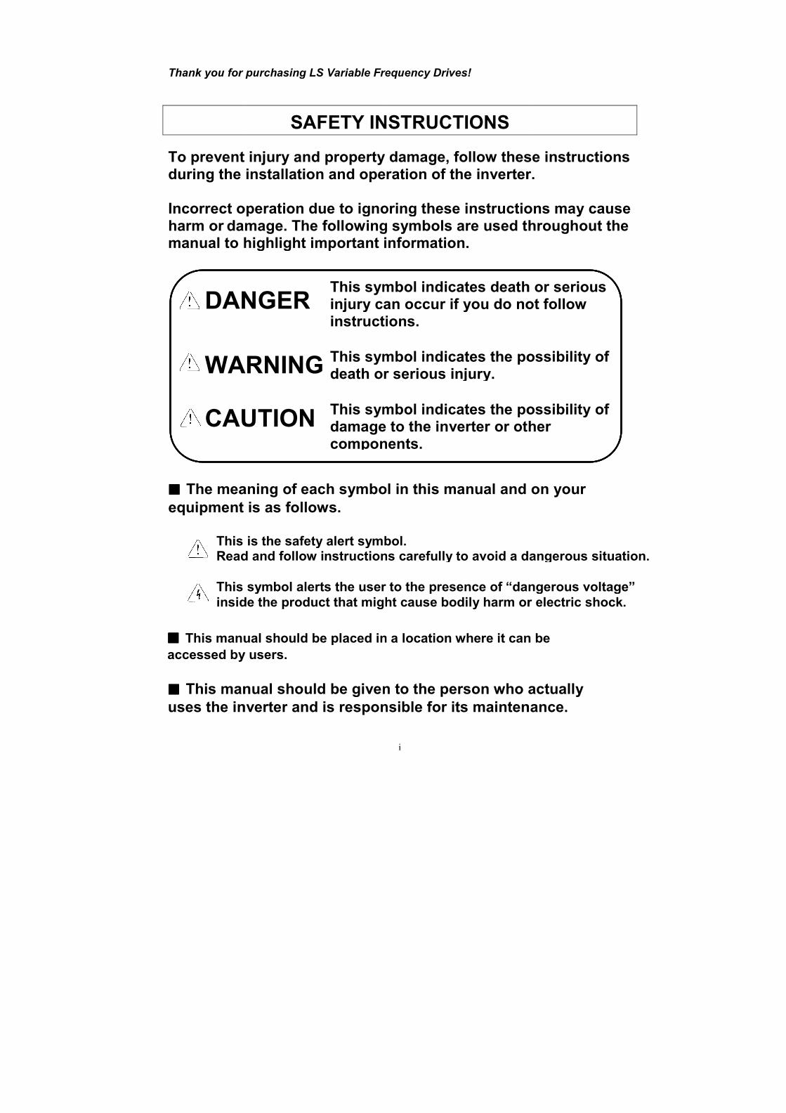
SAFETY INSTRUCTIONS
revent injury and property damage, follow these instructionsduring the installation and operation of the inverter
Incorrect operation due to ignoring amage. The following symbols
manual to highlight important information.
DANGER
WARNING
CAUTION
This symbol indicates the possibility of death or serious injury
This symbol indicates the possibility of damage tocomponents.
This symbol indicates injury can occur if you do not follow instructions.
The meaning of each symbol
equipment is as follows.
This is the safety alert symbol.Read and follow instructions
This symbol alerts the user to the presence of “dangerous voltage”inside the product that might cause
This manual should be placed in a location where it can be
accessed by users.
manual should be given to the person who actually
inverter and is responsible for
i
Frequency Drives!
SAFETY INSTRUCTIONS
revent injury and property damage, follow these instructionsduring the installation and operation of the inverter
Incorrect operation due to ignoring these instructions he following symbols are used throughout the
manual to highlight important information.
This symbol indicates the possibility of death or serious injury.
This symbol indicates the possibility of damage to the inverter or other components.
This symbol indicates death or serious injury can occur if you do not follow instructions.
The meaning of each symbol in this manual and on your
This is the safety alert symbol. Read and follow instructions carefully to avoid a dangerous
This symbol alerts the user to the presence of “dangerous voltage”might cause bodily harm or electric shock.
This manual should be placed in a location where it can be
manual should be given to the person who actually
and is responsible for its maintenance
revent injury and property damage, follow these instructions during the installation and operation of the inverter.
instructions may cause are used throughout the
This symbol indicates the possibility of
This symbol indicates the possibility of the inverter or other
death or serious injury can occur if you do not follow
in this manual and on your
dangerous situation.
This symbol alerts the user to the presence of “dangerous voltage” or electric shock.
This manual should be placed in a location where it can be
manual should be given to the person who actually
maintenance.
Do not remove the cover while power is applied or the unit is in operation. Otherwise, electric shock could occur.
Do not operate
Otherwise, electric shock can occur due to the exposed terminals and bus bars.
Do not remove the cover except for periodic inspections or wiring, even if the input power is not applied.Otherwise, electric
Wiring and periodic inspections should be performed at least 10 minutes after disconnecting the input power and after checking the DC link voltage is discharged with a meter (below 30VDC).Otherwise, elec
Operate the switches with dry hands.Otherwise, electric shock could occur.
Do not use the cable when its insulating tube is damaged. Otherwise, electric shock could occur.
Do not subject the cables to scratches, excessive stresor pinching.Otherwise, electric shock could occur.
Install the inverter on a nonmaterials nearby.
Otherwise, fire could occur.
Disconnect the input power if the inverter Otherwise, it could result in a secondary accident and fire.
Do not touch the inverter remain hot for a couple of minutes.Otherwise, bodily injuries such as skin
Do not apply power to a damaged inverter or to an inverter with parts missing even if the installation is complete.
Otherwise, electric shock could occur.
ii
WARNING
Do not remove the cover while power is applied or the unit is in operation. Otherwise, electric shock could occur.
operate the inverter with the front cover removed.electric shock can occur due to the exposed terminals and bus bars.
Do not remove the cover except for periodic inspections or wiring, even if the input power is not applied.
electric shock can occur due to accessing capacitor banks.
Wiring and periodic inspections should be performed at least 10 minutes after disconnecting the input power and after checking the DC link voltage is discharged with a meter (below 30VDC).Otherwise, electric shock could occur.
Operate the switches with dry hands.Otherwise, electric shock could occur.
Do not use the cable when its insulating tube is damaged. Otherwise, electric shock could occur.
Do not subject the cables to scratches, excessive stresor pinching. Otherwise, electric shock could occur.
CAUTION
Install the inverter on a non-flammable surface. Do not place flammable nearby.
Otherwise, fire could occur.
Disconnect the input power if the inverter Otherwise, it could result in a secondary accident and fire.
Do not touch the inverter after shutting down or disconnecting it.remain hot for a couple of minutes.Otherwise, bodily injuries such as skin-burn or damage
Do not apply power to a damaged inverter or to an inverter with parts missing even if the installation is complete.Otherwise, electric shock could occur.
ii
WARNING
Do not remove the cover while power is applied or the unit is in
the inverter with the front cover removed. electric shock can occur due to the exposed terminals and bus bars.
Do not remove the cover except for periodic inspections or wiring, even if the input power is not applied.
shock can occur due to accessing capacitor banks.
Wiring and periodic inspections should be performed at least 10 minutes after disconnecting the input power and after checking the DC link voltage is discharged with a meter (below 30VDC).
Operate the switches with dry hands.
Do not use the cable when its insulating tube is damaged.
Do not subject the cables to scratches, excessive stress, heavy loads
CAUTION
flammable surface. Do not place flammable
Disconnect the input power if the inverter has been damaged.Otherwise, it could result in a secondary accident and fire.
after shutting down or disconnecting it.remain hot for a couple of minutes.
burn or damage could occur.
Do not apply power to a damaged inverter or to an inverter with parts missing even if the installation is complete.
Do not remove the cover while power is applied or the unit is in
electric shock can occur due to the exposed terminals and bus bars.
Do not remove the cover except for periodic inspections or wiring,
Wiring and periodic inspections should be performed at least 10 minutes after disconnecting the input power and after checking the DC
Do not use the cable when its insulating tube is damaged.
s, heavy loads
flammable surface. Do not place flammable
damaged.
after shutting down or disconnecting it. It will
Do not apply power to a damaged inverter or to an inverter with parts
iii
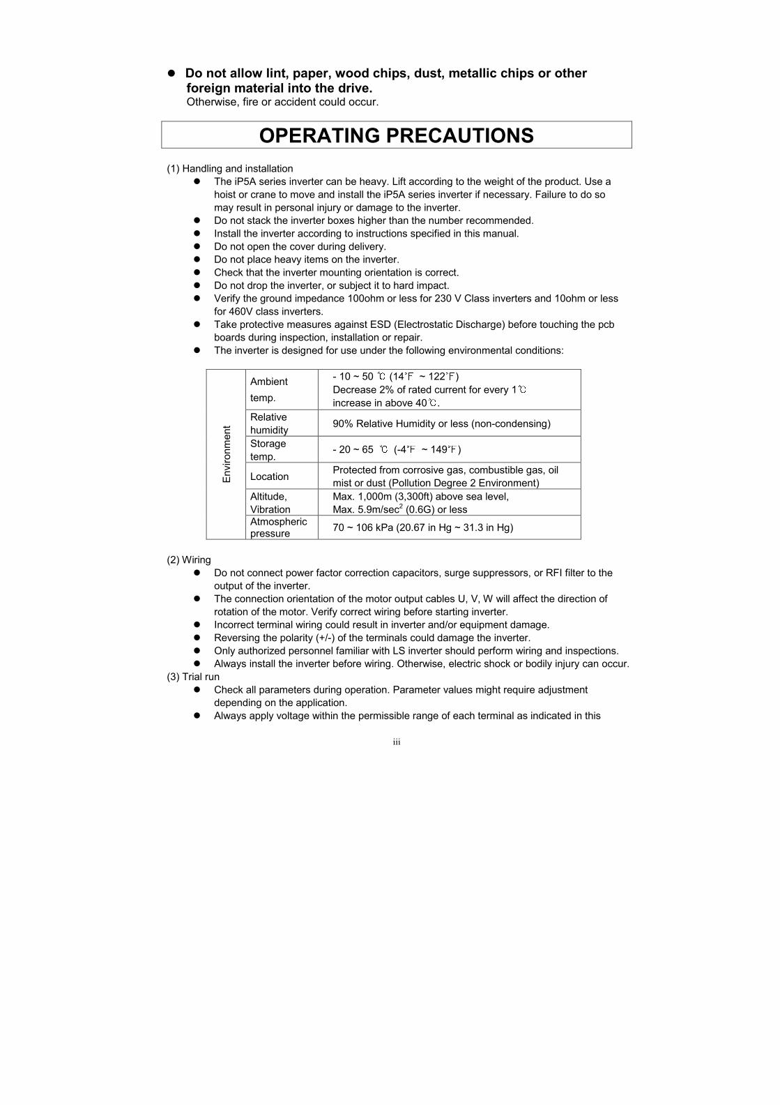
Do not allow lint, paper, wood chips, dust, metallic chips or other foreign material into the drive. Otherwise, fire or accident could occur.
OPERATING PRECAUTIONS
(1) Handling and installation The iP5A series inverter can be heavy. Lift according to the weight of the product. Use a
hoist or crane to move and install the iP5A series inverter if necessary. Failure to do so may result in personal injury or damage to the inverter.
Do not stack the inverter boxes higher than the number recommended. Install the inverter according to instructions specified in this manual. Do not open the cover during delivery. Do not place heavy items on the inverter. Check that the inverter mounting orientation is correct. Do not drop the inverter, or subject it to hard impact. Verify the ground impedance 100ohm or less for 230 V Class inverters and 10ohm or less
for 460V class inverters. Take protective measures against ESD (Electrostatic Discharge) before touching the pcb
boards during inspection, installation or repair. The inverter is designed for use under the following environmental conditions:
Environment
Ambient
temp.
- 10 ~ 50 (14 ~ 122) Decrease 2% of rated current for every 1 increase in above 40.
Relative humidity
90% Relative Humidity or less (non-condensing)
Storage temp.
- 20 ~ 65 (-4 ~ 149) Location
Protected from corrosive gas, combustible gas, oil mist or dust (Pollution Degree 2 Environment)
Altitude, Vibration
Max. 1,000m (3,300ft) above sea level, Max. 5.9m/sec2 (0.6G) or less
Atmospheric pressure
70 ~ 106 kPa (20.67 in Hg ~ 31.3 in Hg)
(2) Wiring
Do not connect power factor correction capacitors, surge suppressors, or RFI filter to the output of the inverter.
The connection orientation of the motor output cables U, V, W will affect the direction of rotation of the motor. Verify correct wiring before starting inverter.
Incorrect terminal wiring could result in inverter and/or equipment damage. Reversing the polarity (+/-) of the terminals could damage the inverter. Only authorized personnel familiar with LS inverter should perform wiring and inspections. Always install the inverter before wiring. Otherwise, electric shock or bodily injury can occur.
(3) Trial run Check all parameters during operation. Parameter values might require adjustment
depending on the application. Always apply voltage within the permissible range of each terminal as indicated in this

iv
manual. Otherwise, inverter damage may result. (4) Operation precautions
When the Auto restart function is selected, the inverter will restart after a fault has occurred. The Stop key on the keypad can only be used to stop the inverter when keypad control is
enabled. Install a separate emergency stop switch if necessary. If a fault reset is made with the run command and /or reference signal present, a sudden
start will occur. Check that the run command and /or reference signal is turned off in advance of resetting any faults. Otherwise an accident could occur.
Do not modify the inverter. Depending on the motor specifications and user ETH overload settings, the motor may not
be protected by electronic thermal function of inverter. The operation of the inverter is intended to be controlled by either keypad command or
control input signals. Do not use a magnetic contactor or any other device that routinely disconnects the inverter and reconnects the inverter to the input supply power for the purpose of starting and stopping the motor.
A noise filter may be installed to reduce the effect of electromagnetic interference. Otherwise nearby electronic equipment may be affected.
In cases with input voltage unbalances, install an AC input reactor. Power Factor capacitors and generators may become overheated and damaged due to
harmonics created by the inverter. Use an insulation-rectified motor or take measures to suppress the micro surge voltage
when driving 460V class motor with inverter. A micro surge voltage attributable to wiring constant is generated at motor terminals, and may deteriorate insulation and damage motor.
Before operating unit and prior to user programming, reset user parameters to default settings.
The Inverter can be set to operate a motor at high-speeds. Verify the speed capability of motor and machinery prior to operating inverter.
Holding torque is not produced when using the DC-Brake function. Install separate equipment when holding torque is required.
(5) Fault prevention precautions
If required, provide a safety backup such as an emergency mechanical brake to prevent any hazardous conditions if the inverter fails during operation.
(6) Maintenance, inspection and parts replacement
Do not megger (hi-pot or insulation resistance) test the power or control circuit of the inverter.
Refer to Chapter 8 for periodic inspection and parts replacement details.
(7) Disposal Handle the inverter as an industrial waste when disposing of it.
(8) General instructions Many of the diagrams and drawings in this instruction manual show the inverter without a cover. Prior to operating the unit, be sure to restore covers and circuit protection according to specifications.

v
Table of Contents
CHAPTER 1 - BASIC INFORMATION .................................................................................................. 1-1 1.1 INSPECTION .............................................................................................................................................. 1-1 1.2 BASIC CONFIGURATION ........................................................................................................................... 1-2
CHAPTER 2 - SPECIFICATION ............................................................................................................. 2-1 2.1 200~230V CLASS (0.75~30KW /1~40HP) ................................................................................................ 2-1 2.2 380~480V CLASS (0.75~30KW / 1~40HP) ............................................................................................... 2-1 2.3 525~600V CLASS (5.5~30KW /7.5~40HP) ............................................................................................... 2-2 2.4 380 ~ 480V CLASS (37~90KW / 50~125HP) ............................................................................................ 2-2 2.5 525 ~ 600V CLASS (37~90KW / 50~150HP) ............................................................................................ 2-3 2.6 380 ~ 480V CLASS (110~450KW / 150~600HP) ...................................................................................... 2-3 2.7 COMMON SPECIFICATIONS ...................................................................................................................... 2-4 2.8 DIMENSIONS ............................................................................................................................................. 2-6
CHAPTER 3 - INSTALLATION .............................................................................................................. 3-1 3.1 INSTALLATION PRECAUTIONS ................................................................................................................. 3-1 3.2 WIRING ..................................................................................................................................................... 3-3
CHAPTER 4 - OPERATION ..................................................................................................................... 4-1 4.1 PROGRAMMING KEYPADS ....................................................................................................................... 4-1 4.2 OPERATING EXAMPLE ............................................................................................................................. 4-7 4.3 VARIOUS FUNCTION SETTING & DESCRIPTION .................................................................................... 4-12 4.4 OPERATION EXAMPLE ........................................................................................................................... 4-18
CHAPTER 5 - PARAMETER LIST ......................................................................................................... 5-1 5.1 PARAMETER GROUPS ............................................................................................................................... 5-1 5.2 PARAMETER LIST ..................................................................................................................................... 5-2
CHAPTER 6 - PARAMETER DESCRIPTION ....................................................................................... 6-1 6.1 DRIVE GROUP [DRV] ............................................................................................................................... 6-1 6.2 FUNCTION 1 GROUP [FU1] ...................................................................................................................... 6-8 6.3 FUNCTION 2 GROUP [FU2] .................................................................................................................... 6-21 6.4 INPUT/OUTPUT GROUP [I/O] ................................................................................................................. 6-33 6.5 APPLICATION GROUP [APP] .................................................................................................................. 6-51
CHAPTER 7 - TROUBLESHOOTING & MAINTENANCE ................................................................ 7-1 7.1 FAULT DISPLAY ........................................................................................................................................ 7-1 7.2 TROUBLESHOOTING ................................................................................................................................. 7-6 7.3 HOW TO CHECK POWER COMPONENTS ................................................................................................. 7-7 7.4 MAINTENANCE ......................................................................................................................................... 7-9
CHAPTER 8 - OPTIONS ........................................................................................................................... 8-1 8.1 OPTION LIST ............................................................................................................................................. 8-1 8.2 EXTERNAL OPTIONS ................................................................................................................................. 8-2
CHAPTER 9 - RS485 COMMUNICATION ............................................................................................ 9-1 9.1 INTRODUCTION ......................................................................................................................................... 9-1 9.2 SPECIFICATION ......................................................................................................................................... 9-2 9.3 OPERATION ............................................................................................................................................... 9-3

vi
9.4 COMMUNICATION PROTOCOL (RS485) ................................................................................................... 9-4 9.5 PARAMETER CODE LIST ........................................................................................................................... 9-8 9.6 TROUBLESHOOTING ............................................................................................................................... 9-12 9.7 ASCII CODE LIST ................................................................................................................................... 9-14
APPENDIX A- UL MARKING ............................................................................................................................ I APPENDIX B- PERIPHERAL DEVICES ......................................................................................................... V APPENDIX C- RELATED PARAMETERS ................................................................................................ VIII DECLARATION OF CONFORMITY ............................................................................................................ IX
EMI / RFI POWER LINE FILTERS ............................................................................................................. XI
1-1
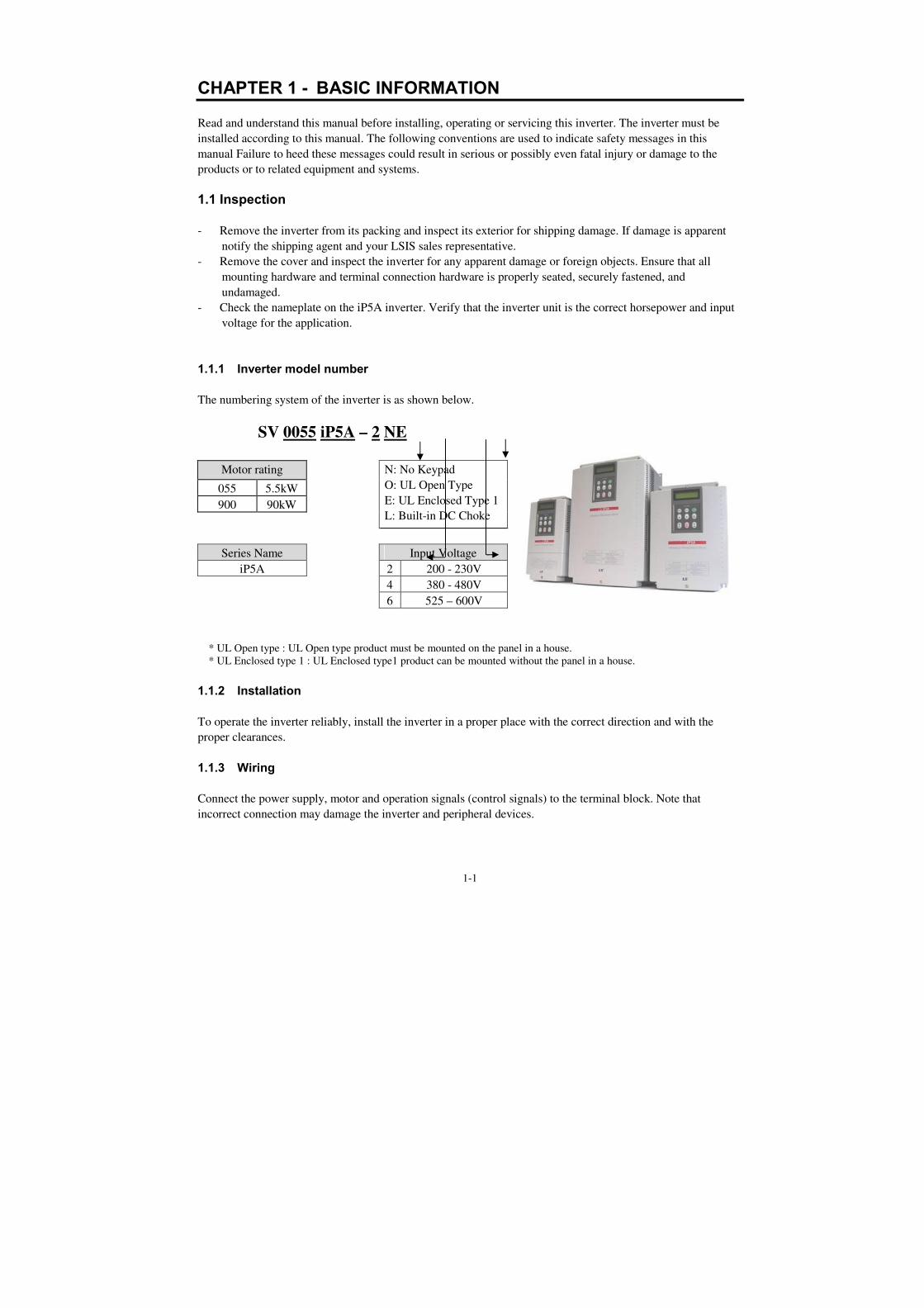
CHAPTER 1 - BASIC INFORMATION
Read and understand this manual before installing, operating or servicing this inverter. The inverter must be
installed according to this manual. The following conventions are used to indicate safety messages in this
manual Failure to heed these messages could result in serious or possibly even fatal injury or damage to the
products or to related equipment and systems.
1.1 Inspection
- Remove the inverter from its packing and inspect its exterior for shipping damage. If damage is apparent
notify the shipping agent and your LSIS sales representative.
- Remove the cover and inspect the inverter for any apparent damage or foreign objects. Ensure that all
mounting hardware and terminal connection hardware is properly seated, securely fastened, and
undamaged.
- Check the nameplate on the iP5A inverter. Verify that the inverter unit is the correct horsepower and input
voltage for the application.
1.1.1 Inverter model number
The numbering system of the inverter is as shown below.
SV 0055 iP5A – 2 NE
Motor rating N: No Keypad
O: UL Open Type
E: UL Enclosed Type 1
L: Built-in DC Choke
055 5.5kW
900 90kW
Series Name Input Voltage
iP5A 2 200 - 230V
4 380 - 480V
6 525 – 600V
* UL Open type : UL Open type product must be mounted on the panel in a house.
* UL Enclosed type 1 : UL Enclosed type1 product can be mounted without the panel in a house.
1.1.2 Installation
To operate the inverter reliably, install the inverter in a proper place with the correct direction and with the
proper clearances.
1.1.3 Wiring
Connect the power supply, motor and operation signals (control signals) to the terminal block. Note that
incorrect connection may damage the inverter and peripheral devices.

Chapter 1 – Basic Information
1-2
1.2 Basic configuration
The following devices are required to operate the inverter. Proper peripheral devices must be selected and
correct connections made to ensure proper operation. An incorrectly applied or installed inverter can result in
system malfunction or reduction in product life as well as component damage. You must read and understand
this manual thoroughly before proceeding.
AC Source Supply
Use a power source with a voltage within the
permissible range of inverter input power
rating.
MCCB or Earth
leakage circuit
breaker (ELB)
Select circuit breakers or fuses in accordance
with applicable national and local codes.
Inline Magnetic
Contactor
Install if necessary. When installed, do not
use it for the purpose of starting or stopping
the drive. It can reduce the life of inverter.
AC Reactor
An AC reactor can be used when the
harmonics are to be reduced and power
factor is to be improved. One must be used
when the inverter is installed on a power
source with greater than 10 times the KVA
rating of the drive.
Inverter (SV-iP5A)
Installation and
wiring
To reliably operate the drive, install the
inverter in the proper orientation and with
proper clearances. Please pay attention, if the
inverter is installed in the panel.
Incorrect terminal wiring could result in the
equipment damage. Control wire of control
circuit must be wired separately with main
ciruit wire to reduce the electric noise.
DC Reactor
A DC reactor may be used together with or
in place of an AC reactor if necessary to
reduce harmonics or improve power factor.
To motor
Do not connect power factor capacitors,
surge arrestors or radio noise filters to the
output side of the inverter.

2-1
CHAPTER 2 - SPECIFICATION
2.1 200~230V Class (0.75~30kW /1~40HP)
Model Number (SVxxxiP5A-2) 008 015 022 037 055 075 110 150 185 220 300
Capacity [kVA] (1)
1.9 3.0 4.6 6.1 9.1 12.2 17.5 22.9 28.2 33.5 43.8
Output
ratings
Fan or
pump
load
motor
rating(2)
HP
1 2 3 5 7.5 10 15 20 25 30 40
kW
0.75 1.5 2.2 3.7 5.5 7.5 11 15 18.5 22 30
Current [A]
(110% overload)
5 8 12 16 24 32 46 60 74 88 115
110% 1Minute (Normal Duty)
General
load
motor
rating(2)
HP
0.5 1 2 3 5 7.5 10 15 20 25 30
kW
0.4 0.75 1.5 2.2 3.7 5.5 7.5 11 15 18.5 22
Current [A]
(150% overload)
2.5 5 8 12 17 23 33 44 54 68 84
150% 1 Minute (Heavy Duty)
Frequency 0.01 ~ 120 Hz
Voltage 200 ~ 230 V(3)
Input
ratings
Voltage 3φ 200 ~ 230 V (-15% ~ +10 %)
Frequency 50/60 Hz (± 5 %)
Protection degree IP20 / UL Type1 IP00 / UL Open(3)
Weight [kg (lbs.)] 4.1
(9.0) 4.2
(9.3) 4.2
(9.3) 4.9
(10.8) 4.9
(10.8) 6
(13.2) 6
(13.2) 13
(28.7) 13.5
(29.8) 20
(44.1) 20
(44.1)
2.2 380~480V Class (0.75~30kW / 1~40HP)
Model Number (SVxxxiP5A-4) 008 015 022 037 055 075 110 150 185 220 300
Capacity [kVA] (1)
2.0 3.2 4.8 6.4 9.6 12.7 19.1 23.9 31.1 35.9 48.6
Output
ratings
Fan or
pump
load
motor
rating(2)
HP
1 2 3 5 7.5 10 15 20 25 30 40
kW
0.75 1.5 2.2 3.7 5.5 7.5 11 15 18.5 22 30
Current [A]
(110% overload)
2.5 4 6 8 12 16 24 30 39 45 61
110% 1Minute (Normal Duty)
General
load
motor
rating(2)
HP
0.5 1 2 3 5.5 7.5 10 15 20 25 30
kW
0.4 0.75 1.5 2.2 3.7 5.5 7.5 11 15 18.5 22
Current [A]/Built-in
DCL Type
(150% overload)
1.25 2.5 4 6 8.8 12 16 22/24 28/30 34/39 44/45
150% 1 Minute (Heavy Duty)
Frequency 0.01 ~ 120 Hz
Voltage 380 ~ 480 V(3)
Input
ratings
Voltage 3φ 380 ~ 480 V (-15% ~ +10 %)
Frequency 50/60 Hz (± 5 %)
Protection degree IP20 / UL Type1 IP00 / UL Open(3)
Weight [kg (lbs.)] Standard Type
4.1 (9.04)
4.2 (9.26)
4.2 (9.26)
4.9 (10.8)
4.9 (10.8)
6 (13.2)
6 (13.2)
12.5 (27.6)
13 (28.7)
20 (44.1)
20 (44.1)
Built-in DCL Type - - - - - - - 19.5
(42.9) 19.5
(42.9) 26.5
(58.3) 26.5
(58.3)
Chapter 2 - Specification
2-2
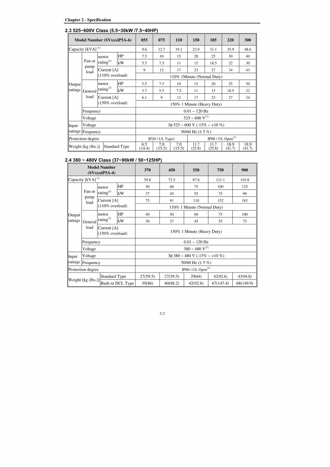
2.3 525~600V Class (5.5~30kW /7.5~40HP)
Model Number (SVxxxiP5A-6) 055 075 110 150 185 220 300
Capacity [kVA] (1)
9.6 12.7 19.1 23.9 31.1 35.9 48.6
Output
ratings
Fan or
pump
load
motor
rating(2)
HP
7.5 10 15 20 25 30 40
kW
5.5 7.5 11 15 18.5 22 30
Current [A]
(110% overload)
9 12 17 23 27 34 43
110% 1Minute (Normal Duty)
General
load
motor
rating(2)
HP
5.5 7.5 10 15 20 25 30
kW
3.7 5.5 7.5 11 15 18.5 22
Current [A]
(150% overload)
6.1 9 12 17 23 27 34
150% 1 Minute (Heavy Duty)
Frequency 0.01 ~ 120 Hz
Voltage 525 ~ 600 V(3)
Input
ratings
Voltage 3φ 525 ~ 600 V (-15% ~ +10 %)
Frequency 50/60 Hz (± 5 %)
Protection degree IP20 / UL Type1 IP00 / UL Open(3)
Weight [kg (lbs.)] Standard Type 6.5
(14.4) 7.0
(15.5) 7.0
(15.5) 11.7
(25.8) 11.7
(25.8) 18.9 (41.7)
18.9 (41.7)
2.4 380 ~ 480V Class (37~90kW / 50~125HP)
Model Number
(SVxxxiP5A-4) 370 450 550 750 900
Capacity [kVA] (1)
59.8 72.5 87.6 121.1 145.8
Output
ratings
Fan or
pump
load
motor
rating(2)
HP
50 60 75 100 125
kW
37 45 55 75 90
Current [A]
(110% overload)
75 91 110 152 183
110% 1 Minute (Normal Duty)
General
load
motor
rating(2)
HP
40 50 60 75 100
kW
30 37 45 55 75
Current [A]
(150% overload) 150% 1 Minute (Heavy Duty)
Frequency 0.01 ~ 120 Hz
Voltage 380 ~ 480 V(3)
Input
ratings
Voltage 3φ 380 ~ 480 V (-15% ~ +10 %)
Frequency 50/60 Hz (± 5 %)
Protection degree IP00 / UL Open(3)
Weight [kg (lbs.)] Standard Type 27(59.5) 27(59.5) 29(64) 42(92.6) 43(94.8)
Built-in DCL Type 39(86) 40(88.2) 42(92.6) 67(147.4) 68(149.9)
Chapter 2 - Specification
2-3
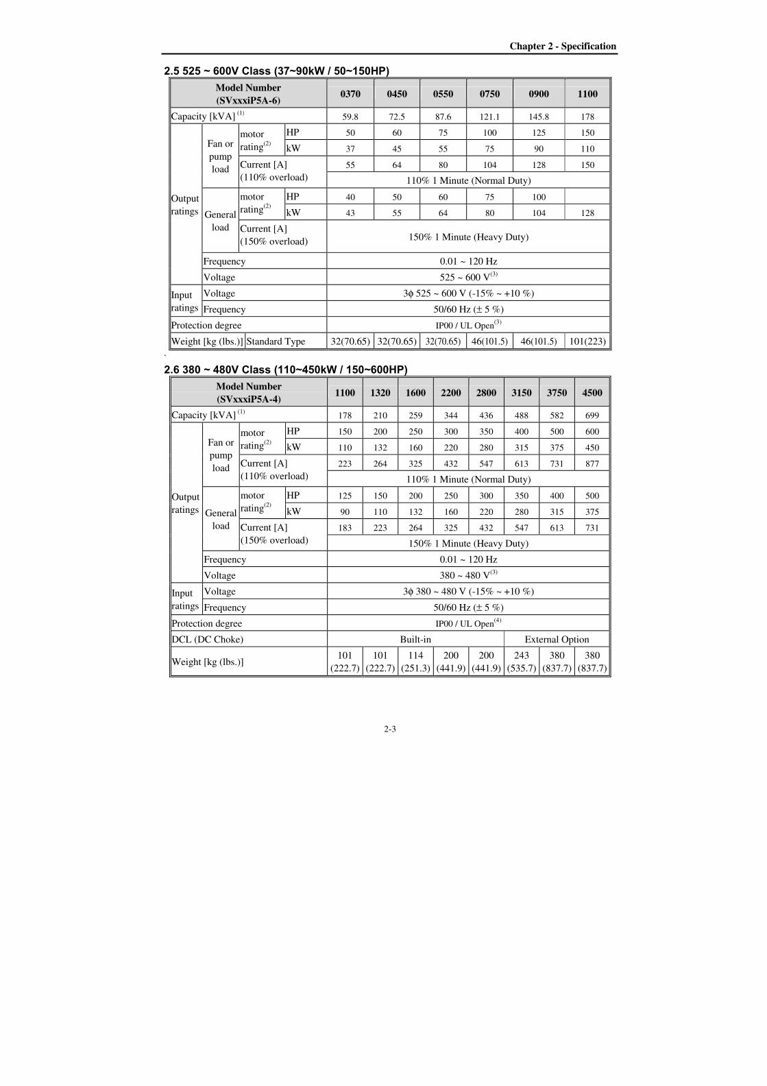
2.5 525 ~ 600V Class (37~90kW / 50~150HP)
Model Number
(SVxxxiP5A-6) 0370 0450 0550 0750 0900 1100
Capacity [kVA] (1)
59.8 72.5 87.6 121.1 145.8 178
Output
ratings
Fan or
pump
load
motor
rating(2)
HP
50 60 75 100 125 150
kW
37 45 55 75 90 110
Current [A]
(110% overload)
55 64 80 104 128 150
110% 1 Minute (Normal Duty)
General
load
motor
rating(2)
HP
40 50 60 75 100
kW
43 55 64 80 104 128
Current [A]
(150% overload) 150% 1 Minute (Heavy Duty)
Frequency 0.01 ~ 120 Hz
Voltage 525 ~ 600 V(3)
Input
ratings
Voltage 3φ 525 ~ 600 V (-15% ~ +10 %)
Frequency 50/60 Hz (± 5 %)
Protection degree IP00 / UL Open(3)
Weight [kg (lbs.)] Standard Type 32(70.65) 32(70.65) 32(70.65) 46(101.5) 46(101.5) 101(223)
`
2.6 380 ~ 480V Class (110~450kW / 150~600HP)
Model Number
(SVxxxiP5A-4) 1100 1320 1600 2200 2800 3150 3750 4500
Capacity [kVA] (1)
178 210 259 344 436 488 582 699
Output
ratings
Fan or
pump
load
motor
rating(2)
HP
150 200 250 300 350 400 500 600
kW
110 132 160 220 280 315 375 450
Current [A]
(110% overload)
223 264 325 432 547 613 731 877
110% 1 Minute (Normal Duty)
General
load
motor
rating(2)
HP
125 150 200 250 300 350 400 500
kW
90 110 132 160 220 280 315 375
Current [A]
(150% overload)
183 223 264 325 432 547 613 731
150% 1 Minute (Heavy Duty)
Frequency 0.01 ~ 120 Hz
Voltage 380 ~ 480 V(3)
Input
ratings
Voltage 3φ 380 ~ 480 V (-15% ~ +10 %)
Frequency 50/60 Hz (± 5 %)
Protection degree IP00 / UL Open(4)
DCL (DC Choke) Built-in External Option
Weight [kg (lbs.)] 101
(222.7)
101
(222.7)
114
(251.3)
200
(441.9)
200
(441.9)
243
(535.7)
380
(837.7)
380
(837.7)
Chapter 2 - Specification
2-4
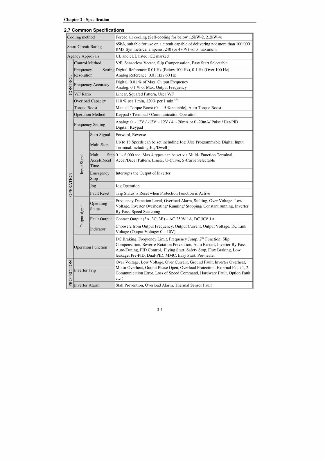
2.7 Common Specifications
Cooling method Forced air cooling (Self-cooling for below 1.5kW-2, 2.2kW-4)
Short Circuit Rating 65kA, suitable for use on a circuit capable of delivering not more than 100,000
RMS Symmetrical amperes, 240 (or 480V) volts maximum
Agency Approvals UL and cUL listed, CE marked
CO
NT
RO
L
Control Method V/F, Sensorless Vector, Slip Compensation, Easy Start Selectable
Frequency Setting
Resolution
Digital Reference: 0.01 Hz (Below 100 Hz), 0.1 Hz (Over 100 Hz)
Analog Reference: 0.01 Hz / 60 Hz
Frequency Accuracy Digital: 0.01 % of Max. Output Frequency
Analog: 0.1 % of Max. Output Frequency
V/F Ratio Linear, Squared Pattern, User V/F
Overload Capacity 110 % per 1 min, 120% per 1 min (5)
Torque Boost Manual Torque Boost (0 ~ 15 % settable), Auto Torque Boost
OP
ER
AT
ION
Operation Method Keypad / Terminal / Communication Operation
Frequency Setting Analog: 0 ~ 12V / -12V ~ 12V / 4 ~ 20mA or 0~20mA/ Pulse / Ext-PID
Digital: Keypad
Inp
ut
Sig
nal
Start Signal Forward, Reverse
Multi-Step Up to 18 Speeds can be set including Jog (Use Programmable Digital Input
Terminal,Including Jog/Dwell )
Multi Step
Accel/Decel
Time
0.1~ 6,000 sec, Max 4 types can be set via Multi- Function Terminal.
Accel/Decel Pattern: Linear, U-Curve, S-Curve Selectable
Emergency
Stop
Interrupts the Output of Inverter
Jog Jog Operation
Fault Reset Trip Status is Reset when Protection Function is Active
Ou
tpu
t si
gn
al Operating
Status
Frequency Detection Level, Overload Alarm, Stalling, Over Voltage, Low
Voltage, Inverter Overheating/ Running/ Stopping/ Constant running, Inverter
By-Pass, Speed Searching
Fault Output Contact Output (3A, 3C, 3B) – AC 250V 1A, DC 30V 1A
Indicator Choose 2 from Output Frequency, Output Current, Output Voltage, DC Link
Voltage (Output Voltage: 0 ~ 10V)
Operation Function
DC Braking, Frequency Limit, Frequency Jump, 2nd
Function, Slip
Compensation, Reverse Rotation Prevention, Auto Restart, Inverter By-Pass,
Auto-Tuning, PID Control, Flying Start, Safety Stop, Flux Braking, Low
leakage, Pre-PID, Dual-PID, MMC, Easy Start, Pre-heater
PR
OT
EC
TIO
N
Inverter Trip
Over Voltage, Low Voltage, Over Current, Ground Fault, Inverter Overheat,
Motor Overheat, Output Phase Open, Overload Protection, External Fault 1, 2,
Communication Error, Loss of Speed Command, Hardware Fault, Option Fault
etc (
Inverter Alarm Stall Prevention, Overload Alarm, Thermal Sensor Fault

Chapter 2 - Specification
2-5
DIS
PL
AY
Key
pad
Operation
Information
Output Frequency, Output Current, Output Voltage, Frequency Set Value,
Operating Speed, DC Voltage, Integrating Wattmeter, Fan ON time, Run-time,
Last Trip Time
Trip
Information
Trips Indication when the Protection Function activates. Max. 5 Faults are
saved. Last Trip Time.
EN
VIR
ON
ME
NT
Ambient Temperature - 10 ~ 50 (14 ~ 122)
Decrease 2% of rated current for every 1increase in above 40.
Storage Temperature -20 ~ 65 (14 ~ 149)
Ambient Humidity Less Than 90 % RH Max. (Non-Condensing)
Altitude – Vibration Below 1,000m (3,300ft), Below 5.9m/sec2 (0.6g)
Application Site Pollution degree 2, No Corrosive Gas, Combustible Gas, Oil Mist, or Dust
(1) Rated capacity (√3×V×I) is based on 220V for 200V class and 460V for 400V class.
(2) Indicates the maximum applicable capacity when using a 4-Pole standard motor.
(3) IP20 or UL Enclosed Type1 can be provided by the option.
(4) IP20 or UL Enclosed Type1 is not provided.
(5) Overload rating 120%, 1 min is based on ambient 25.
Chapter 2 - Specification
2-6
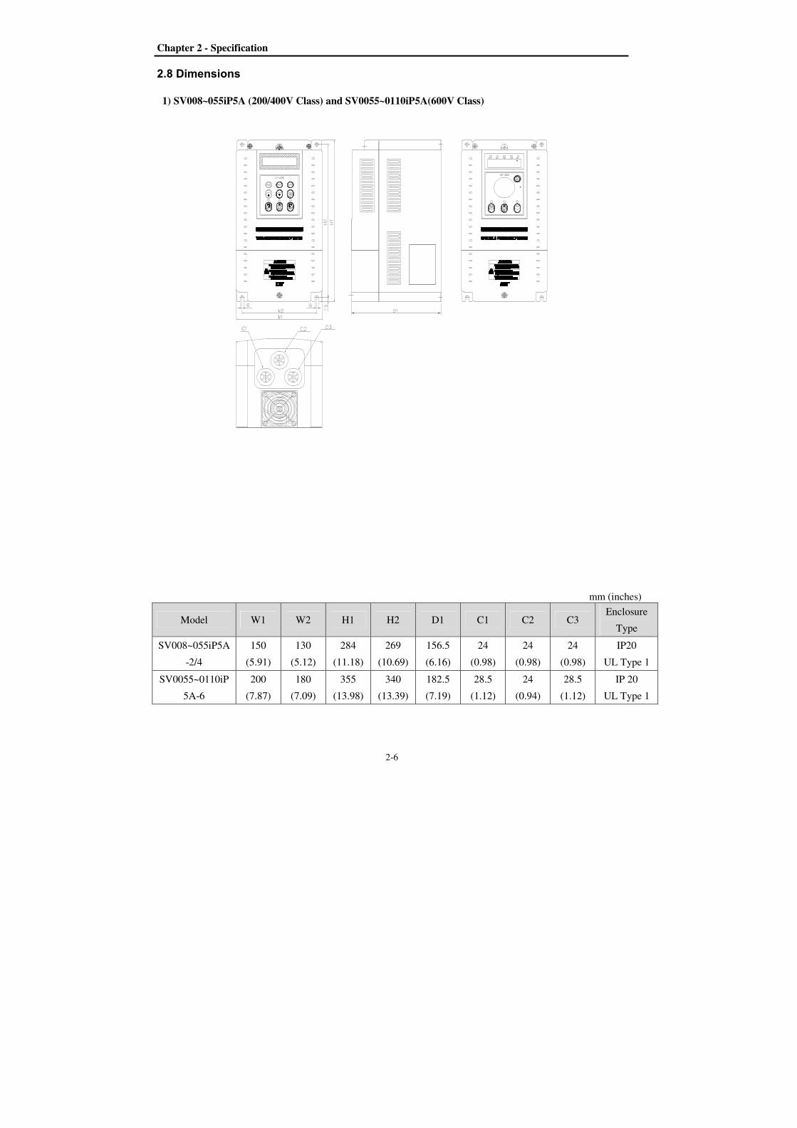
2.8 Dimensions
1) SV008~055iP5A (200/400V Class) and SV0055~0110iP5A(600V Class)
mm (inches)
Model W1 W2 H1 H2 D1 C1 C2 C3 Enclosure
Type
SV008~055iP5A
-2/4
150
(5.91)
130
(5.12)
284
(11.18)
269
(10.69)
156.5
(6.16)
24
(0.98)
24
(0.98)
24
(0.98)
IP20
UL Type 1
SV0055~0110iP
5A-6
200
(7.87)
180
(7.09)
355
(13.98)
340
(13.39)
182.5
(7.19)
28.5
(1.12)
24
(0.94)
28.5
(1.12)
IP 20
UL Type 1
Chapter 2 - Specification
2-7
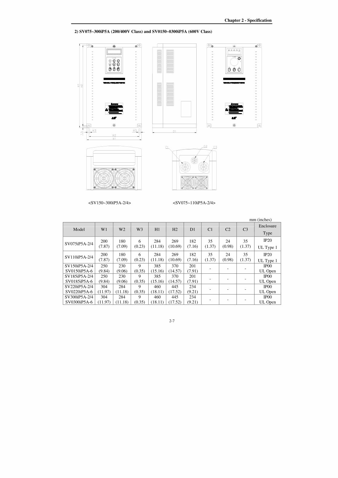
2) SV075~300iP5A (200/400V Class) and SV0150~0300iP5A (600V Class)
<SV150~300iP5A-2/4> <SV075~110iP5A-2/4>
mm (inches)
Model W1 W2 W3 H1 H2 D1 C1 C2 C3 Enclosure
Type
SV075iP5A-2/4 200
(7.87)
180
(7.09)
6
(0.23)
284
(11.18)
269
(10.69)
182
(7.16)
35
(1.37)
24
(0.98)
35
(1.37)
IP20
UL Type 1
SV110iP5A-2/4 200
(7.87)
180
(7.09)
6
(0.23)
284
(11.18)
269
(10.69)
182
(7.16)
35
(1.37)
24
(0.98)
35
(1.37)
IP20
UL Type 1
SV150iP5A-2/4
SV0150iP5A-6
250
(9.84)
230
(9.06)
9
(0.35)
385
(15.16)
370
(14.57)
201
(7.91) - - -
IP00
UL Open
SV185iP5A-2/4
SV0185iP5A-6
250
(9.84)
230
(9.06)
9
(0.35)
385
(15.16)
370
(14.57)
201
(7.91) - - -
IP00
UL Open
SV220iP5A-2/4
SV0220iP5A-6
304
(11.97)
284
(11.18)
9
(0.35)
460
(18.11)
445
(17.52)
234
(9.21) - - -
IP00
UL Open
SV300iP5A-2/4
SV0300iP5A-6
304
(11.97)
284
(11.18)
9
(0.35)
460
(18.11)
445
(17.52)
234
(9.21) - - -
IP00
UL Open
Chapter 2 - Specification
2-8
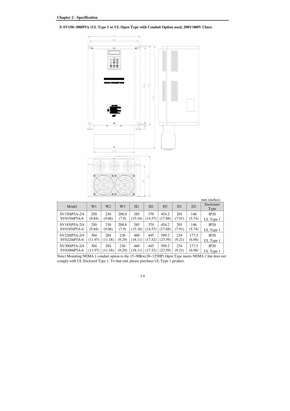
3) SV150~300iP5A (UL Type 1 or UL Open Type with Conduit Option used, 200V/400V Class)
mm (inches)
Model W1 W2 W3 H1 H2 H3 D1 D2 Enclosure
Type
SV150iP5A-2/4
SV0150iP5A-6
250
(9.84)
230
(9.06)
200.8
(7.9)
385
(15.16)
370
(14.57)
454.2
(17.88)
201
(7.91)
146
(5.74) IP20
UL Type 1
SV185iP5A-2/4
SV0185iP5A-6
250
(9.84)
230
(9.06)
200.8
(7.9)
385
(15.16)
370
(14.57)
454.2
(17.88)
201
(7.91)
146
(5.74) IP20
UL Type 1
SV220iP5A-2/4
SV0220iP5A-6
304
(11.97)
284
(11.18)
236
(9.29)
460
(18.11)
445
(17.52)
599.2
(23.59)
234
(9.21)
177.5
(6.98) IP20
UL Type 1
SV300iP5A-2/4
SV0300iP5A-6
304
(11.97)
284
(11.18)
236
(9.29)
460
(18.11)
445
(17.52)
599.2
(23.59)
234
(9.21)
177.5
(6.98) IP20
UL Type 1
Note) Mounting NEMA 1 conduit option to the 15~90Kw(20~125HP) Open Type meets NEMA 1 but does not
comply with UL Enclosed Type 1. To that end, please purchase UL Type 1 product.
Chapter 2 - Specification
2-9
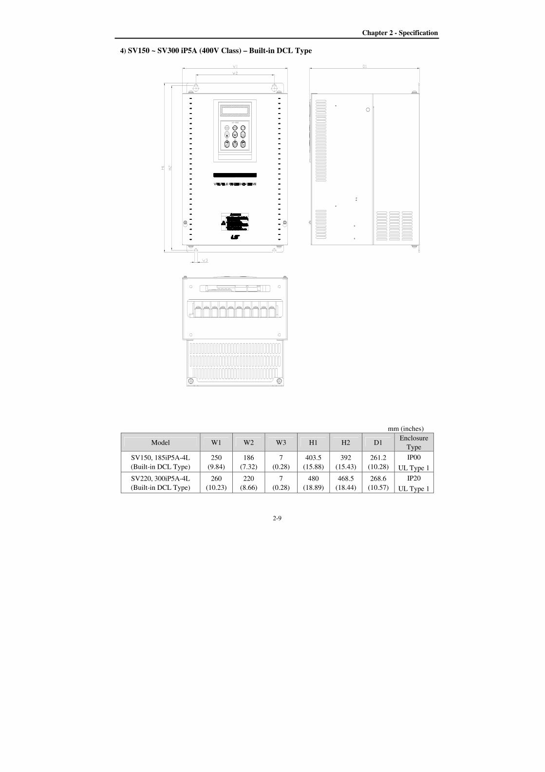
4) SV150 ~ SV300 iP5A (400V Class) – Built-in DCL Type
mm (inches)
Model W1 W2 W3 H1 H2 D1 Enclosure
Type
SV150, 185iP5A-4L
(Built-in DCL Type)
250
(9.84)
186
(7.32)
7
(0.28)
403.5
(15.88)
392
(15.43)
261.2
(10.28)
IP00
UL Type 1
SV220, 300iP5A-4L
(Built-in DCL Type)
260
(10.23)
220
(8.66)
7
(0.28)
480
(18.89)
468.5
(18.44)
268.6
(10.57)
IP20
UL Type 1
Chapter 2 - Specification
2-10
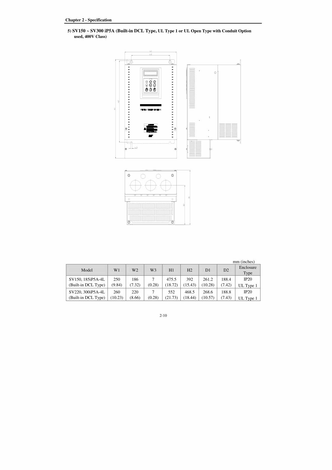
5) SV150 ~ SV300 iP5A (Built-in DCL Type, UL Type 1 or UL Open Type with Conduit Option
used, 400V Class)
mm (inches)
Model W1 W2 W3 H1 H2 D1 D2 Enclosure
Type
SV150, 185iP5A-4L
(Built-in DCL Type)
250
(9.84)
186
(7.32)
7
(0.28)
475.5
(18.72)
392
(15.43)
261.2
(10.28)
188.4
(7.42)
IP20
UL Type 1
SV220, 300iP5A-4L
(Built-in DCL Type)
260
(10.23)
220
(8.66)
7
(0.28)
552
(21.73)
468.5
(18.44)
268.6
(10.57)
188.8
(7.43)
IP20
UL Type 1
Chapter 2 - Specification
2-11
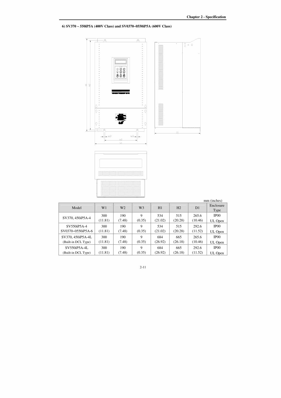
6) SV370 ~ 550iP5A (400V Class) and SV0370~0550iP5A (600V Class)
mm (inches)
Model W1 W2 W3 H1 H2 D1 Enclosure
Type
SV370, 450iP5A-4 300
(11.81)
190
(7.48)
9
(0.35)
534
(21.02)
515
(20.28)
265.6
(10.46)
IP00
UL Open
SV550iP5A-4
SV0370~0550iP5A-6
300
(11.81)
190
(7.48)
9
(0.35)
534
(21.02)
515
(20.28)
292.6
(11.52)
IP00
UL Open
SV370, 450iP5A-4L
(Built-in DCL Type)
300
(11.81)
190
(7.48)
9
(0.35)
684
(26.92)
665
(26.18)
265.6
(10.46)
IP00
UL Open
SV550iP5A-4L
(Built-in DCL Type)
300
(11.81)
190
(7.48)
9
(0.35)
684
(26.92)
665
(26.18)
292.6
(11.52)
IP00
UL Open

Chapter 2 - Specification
2-12
7) SV370~550iP5A (UL Type 1 or UL Open Type with Conduit Option Used, 400V Class)
mm (inches)
Model W1 W2 W3 H1 H2 D1 D2 Enclosure
Type
SV370, 450iP5A-4 300
(11.81)
190
(7.48)
9
(0.35)
642
(25.28)
515
(20.28)
265.6
(10.46)
163.4
(6.43)
IP20
UL Type 1
SV550iP5A-4 300
(11.81)
190
(7.48)
9
(0.35)
642
(25.28)
515
(20.28)
292.6
(11.52)
190.4
(7.5)
IP20
UL Type 1
SV370, 450iP5A-4L
(Built-in DCL Type)
300
(11.81)
190
(7.48)
9
(0.35)
792
(31.18)
665
(26.18)
265.6
(10.46)
163.4
(6.43)
IP20
UL Type 1
SV550iP5A-4L
(Built-in DCL Type)
300
(11.81)
190
(7.48)
9
(0.35)
792
(31.18)
665
(26.18)
292.6
(11.52)
190.4
(7.5)
IP20
UL Type 1
Note) Mounting NEMA 1 conduit option to the 15~90Kw(20~125HP) Open Type meets NEMA 1 but does not
comply with UL Enclosed Type 1. To that end, please purchase UL Type 1 product.
Chapter 2 - Specification
2-13
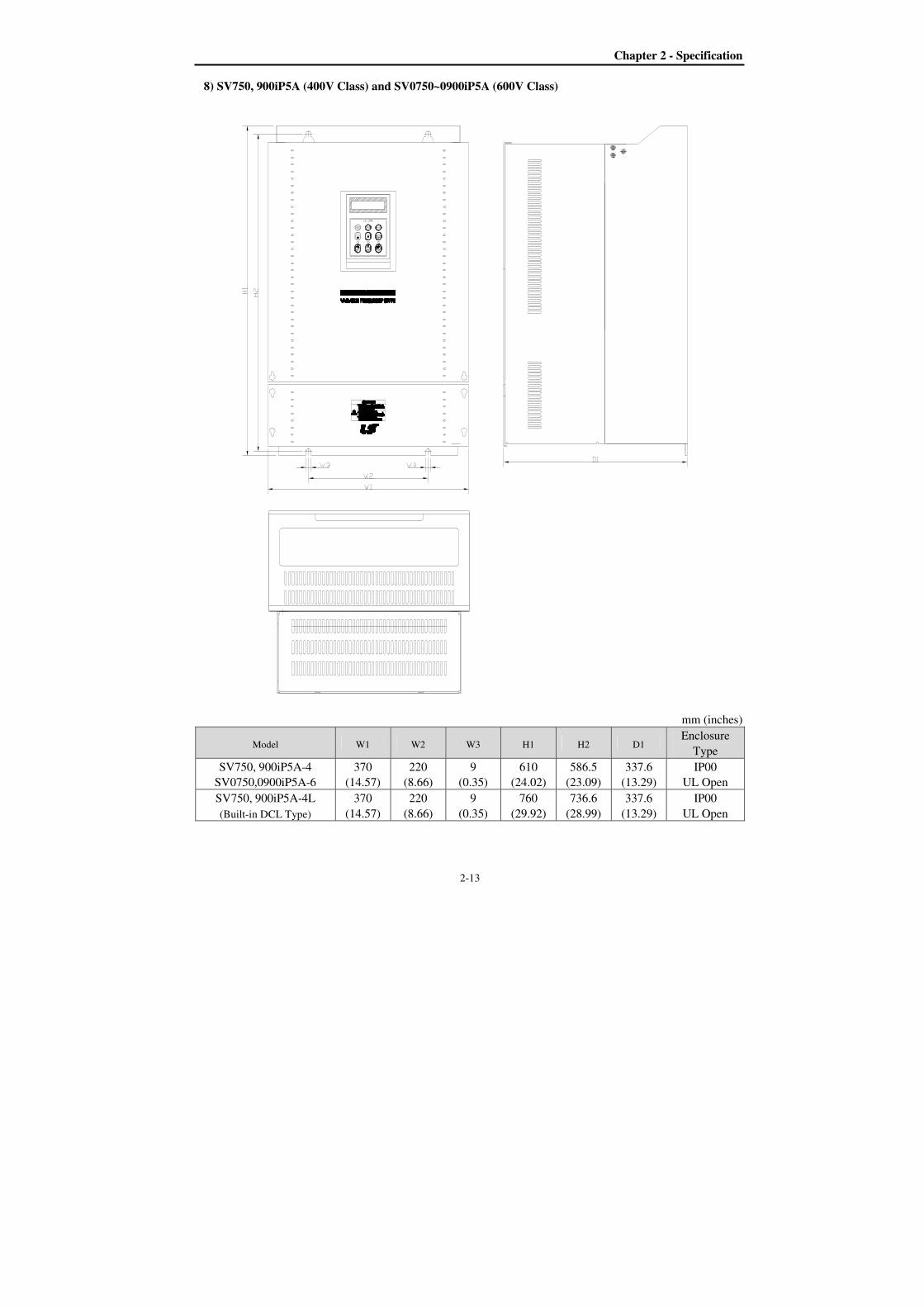
8) SV750, 900iP5A (400V Class) and SV0750~0900iP5A (600V Class)
mm (inches)
Model W1 W2 W3 H1 H2 D1 Enclosure
Type
SV750, 900iP5A-4
SV0750,0900iP5A-6
370
(14.57)
220
(8.66)
9
(0.35)
610
(24.02)
586.5
(23.09)
337.6
(13.29)
IP00
UL Open
SV750, 900iP5A-4L
(Built-in DCL Type)
370
(14.57)
220
(8.66)
9
(0.35)
760
(29.92)
736.6
(28.99)
337.6
(13.29)
IP00
UL Open
Chapter 2 - Specification
2-14
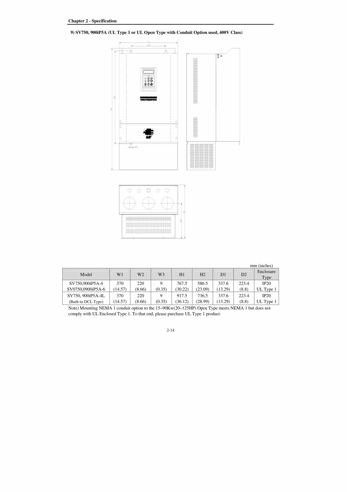
9) SV750, 900iP5A (UL Type 1 or UL Open Type with Conduit Option used, 400V Class)
mm (inches)
Model W1 W2 W3 H1 H2 D1 D2 Enclosure
Type
SV750,900iP5A-4
SV0750,0900iP5A-6
370
(14.57)
220
(8.66)
9
(0.35)
767.5
(30.22)
586.5
(23.09)
337.6
(13.29)
223.4
(8.8)
IP20
UL Type 1
SV750, 900iP5A-4L
(Built-in DCL Type)
370
(14.57)
220
(8.66)
9
(0.35)
917.5
(36.12)
736.5
(28.99)
337.6
(13.29)
223.4
(8.8)
IP20
UL Type 1
Note) Mounting NEMA 1 conduit option to the 15~90Kw(20~125HP) Open Type meets NEMA 1 but does not
comply with UL Enclosed Type 1. To that end, please purchase UL Type 1 product.
Chapter 2 - Specification
2-15
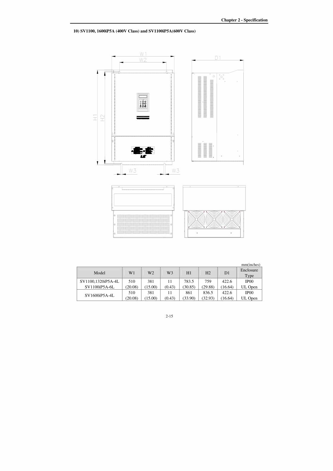
10) SV1100, 1600iP5A (400V Class) and SV1100iP5A(600V Class)
mm(inches)
Model W1 W2 W3 H1 H2 D1 Enclosure
Type
SV1100,1320iP5A-4L
SV1100iP5A-6L
510
(20.08)
381
(15.00)
11
(0.43)
783.5
(30.85)
759
(29.88)
422.6
(16.64)
IP00
UL Open
SV1600iP5A-4L 510
(20.08)
381
(15.00)
11
(0.43)
861
(33.90)
836.5
(32.93)
422.6
(16.64)
IP00
UL Open
Chapter 2 - Specification
2-16
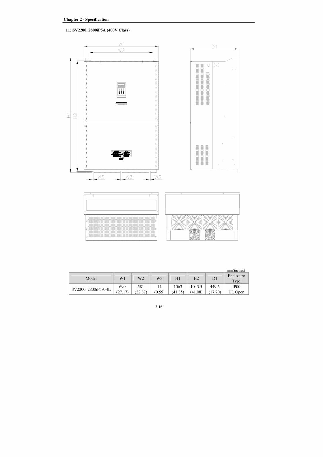
11) SV2200, 2800iP5A (400V Class)
mm(inches)
Model W1 W2 W3 H1 H2 D1 Enclosure
Type
SV2200, 2800iP5A-4L 690
(27.17)
581
(22.87)
14
(0.55)
1063
(41.85)
1043.5
(41.08)
449.6
(17.70)
IP00
UL Open
Chapter 2 - Specification
2-17
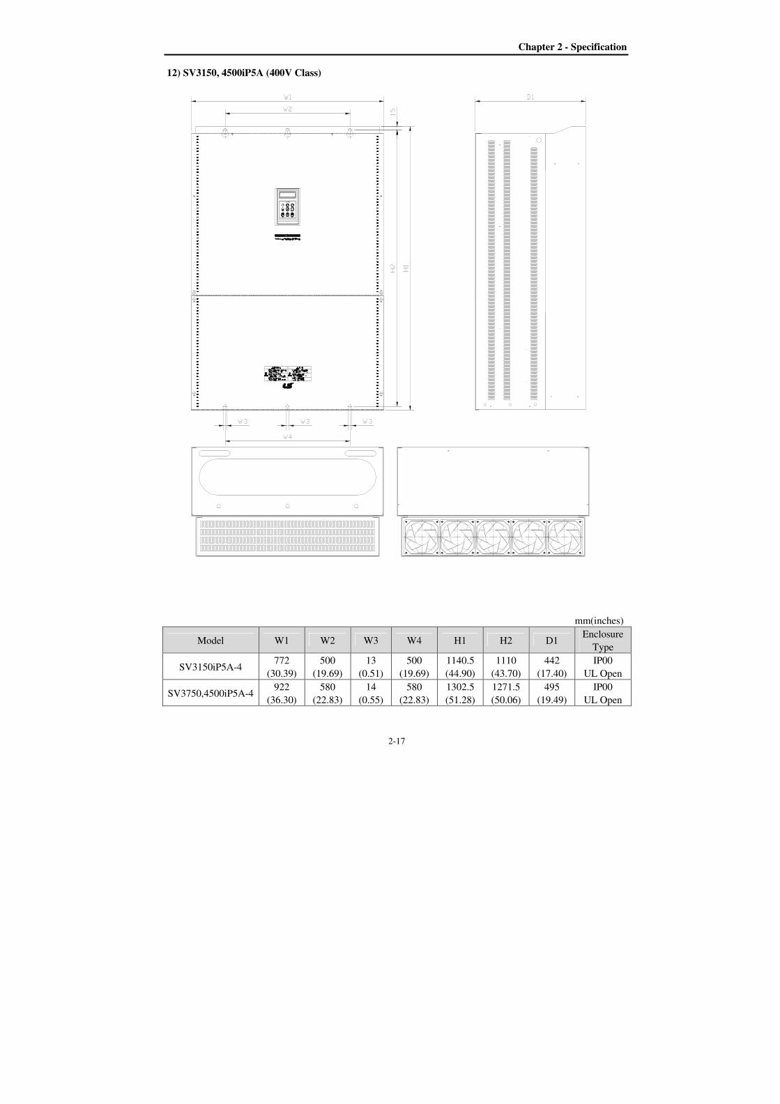
12) SV3150, 4500iP5A (400V Class)
mm(inches)
Model W1 W2 W3 W4 H1 H2 D1 Enclosure
Type
SV3150iP5A-4 772
(30.39)
500
(19.69)
13
(0.51)
500
(19.69)
1140.5
(44.90)
1110
(43.70)
442
(17.40)
IP00
UL Open
SV3750,4500iP5A-4 922
(36.30)
580
(22.83)
14
(0.55)
580
(22.83)
1302.5
(51.28)
1271.5
(50.06)
495
(19.49)
IP00
UL Open

3-1
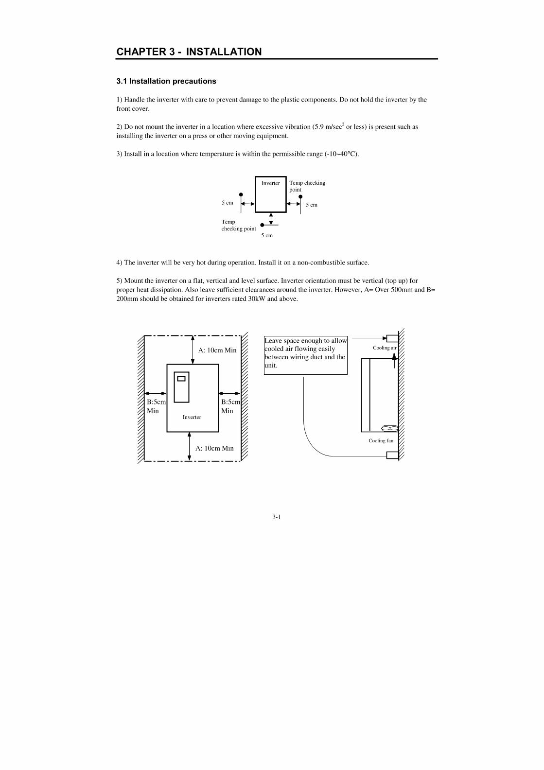
Cooling fan
Cooling air
Leave space enough to allow
cooled air flowing easily
between wiring duct and the
unit.
CHAPTER 3 - INSTALLATION
3.1 Installation precautions
1) Handle the inverter with care to prevent damage to the plastic components. Do not hold the inverter by the
front cover.
2) Do not mount the inverter in a location where excessive vibration (5.9 m/sec2 or less) is present such as
installing the inverter on a press or other moving equipment.
3) Install in a location where temperature is within the permissible range (-10~40°C).
4) The inverter will be very hot during operation. Install it on a non-combustible surface.
5) Mount the inverter on a flat, vertical and level surface. Inverter orientation must be vertical (top up) for
proper heat dissipation. Also leave sufficient clearances around the inverter. However, A= Over 500mm and B=
200mm should be obtained for inverters rated 30kW and above.
Temp
checking point
Temp checking
point
5 cm
5 cm
5 cm
Inverter
B:5cm
Min
B:5cm
Min Inverter
A: 10cm Min
A: 10cm Min

Chapter 3 - Installation
6) Do not mount the inverter in dir
7) The inverter shall be mounted in a Pollution Degree 2 environment. If the inverter is going to be installed in
an environment with a high probability of dust,
the inerter must be located inside the appropriate electrical enclosure of the proper NEMA or IP rating.
8) When two or more inverters are installed or a ventilation fan is mounted in inverter panel, the inverters and
ventilation fan must b
the inverters below the permissible value. If they are installed in improper positions, the ambient temperature of
the inverters will rise.
.
9) Install the inverter using screws or bolts to insure the inverter
Inverter
GOOD (O)
Inverter
Cooling fan
Panel
[When installing several inverters in a panel]
Installation
3-
6) Do not mount the inverter in direct sunlight or near other heat sources.
7) The inverter shall be mounted in a Pollution Degree 2 environment. If the inverter is going to be installed in
an environment with a high probability of dust, metallic
the inerter must be located inside the appropriate electrical enclosure of the proper NEMA or IP rating.
When two or more inverters are installed or a ventilation fan is mounted in inverter panel, the inverters and
ventilation fan must be installed in proper positions with extreme care taken to keep the ambient temperature of
the inverters below the permissible value. If they are installed in improper positions, the ambient temperature of
the inverters will rise.
Install the inverter using screws or bolts to insure the inverter
CAUTION
Risk of Electric ShockMore than one disconnect switch may be required to de-energize the equipment before servicing.
BAD (X)
Inverter
Panel
Inverter
Inverter
[When installing several inverters in a panel]
-2
ect sunlight or near other heat sources.
7) The inverter shall be mounted in a Pollution Degree 2 environment. If the inverter is going to be installed in
particles, mists, corrosive gases, or other
the inerter must be located inside the appropriate electrical enclosure of the proper NEMA or IP rating.
When two or more inverters are installed or a ventilation fan is mounted in inverter panel, the inverters and
e installed in proper positions with extreme care taken to keep the ambient temperature of
the inverters below the permissible value. If they are installed in improper positions, the ambient temperature of
Install the inverter using screws or bolts to insure the inverter is firmly fastened.
CAUTION Risk of Electric Shock
More than one disconnect switch may be required energize the equipment before servicing.
Ventilating fan
GOOD (O)
[When installing a ventilating fan in a panel]
7) The inverter shall be mounted in a Pollution Degree 2 environment. If the inverter is going to be installed in
particles, mists, corrosive gases, or other contaminates,
the inerter must be located inside the appropriate electrical enclosure of the proper NEMA or IP rating.
When two or more inverters are installed or a ventilation fan is mounted in inverter panel, the inverters and
e installed in proper positions with extreme care taken to keep the ambient temperature of
the inverters below the permissible value. If they are installed in improper positions, the ambient temperature of
BAD (X)
[When installing a ventilating fan in a panel]
Chapter 3 - Installation
3-3
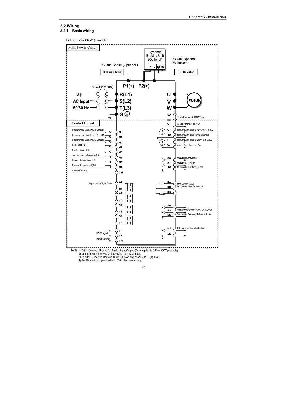
3.2 Wiring 3.2.1 Basic wiring
1) For 0.75~30kW (1~40HP)
AC Input
50/60 Hz
U
V
W
G
R(L1)
S(L2)
T(L3)
DB Unit(Optional)
DB Resistor
φ 3
MCCB(Option)
M1
M2
M3
M4
M6
M8
M7
MOTOR
Programmable Digital Input 1(Speed L)
Programmable Digital Input 2(Speed M)
Programmable Digital Input 3(Speed H)
Fault Reset (RST)
Jog Frequency Reference (JOG)
Forward Run command (FX)
Reverse Run command (RX)
Common Terminal
Fault Contact Ouput less than AC250V (DC30V), 1A
P2(+)
P1(+)
DC Bus Choke (Optional )
Dynamic Braking Unit (Optional)
P N B1 B2
DC Bus Choke DB Resistor
M5 Inverter Disable (BX)
V+
V1
5G
V-
I
Analog Power Source (+12V)
+ -
+ -
Analog Power Source (-12V)
Frequency reference (0~20mA or 4~20mA)
Frequency reference (0~12V,V1S : -12~12V)
Frequency reference common terminal
S1
S0
5G
Output Frequency Meter
Output Voltage Meter
Common for output meter signal
3A
3C
3B
5G
B0
A0
Frequency Reference (Pulse : 0 ~ 100kHz)
Common for Frequency Reference (Pulse)
5G
NT External motor thermal detection
A1
C1
A2
C2
A3
C3
A4
C4
C-
C+
CM
RS485 Signal
RS485 Common
CM
Programmable Digital Output
SA
SB Safety Function (NC) 600V Only
Control Circuit
Main Power Circuit
Note :1) 5G is Common Ground for Analog Input/Output. (Only applied to 0.75 ~ 30kW products) 2) Use terminal V1 for V1, V1S (0~12V, -12 ~ 12V) input. 3) To add DC reactor, Remove DC Bus Choke and connect to P1(+), P2(+). 4) SA,SB terminal is provided with 600V class model only.
Chapter 3 - Installation
3-4
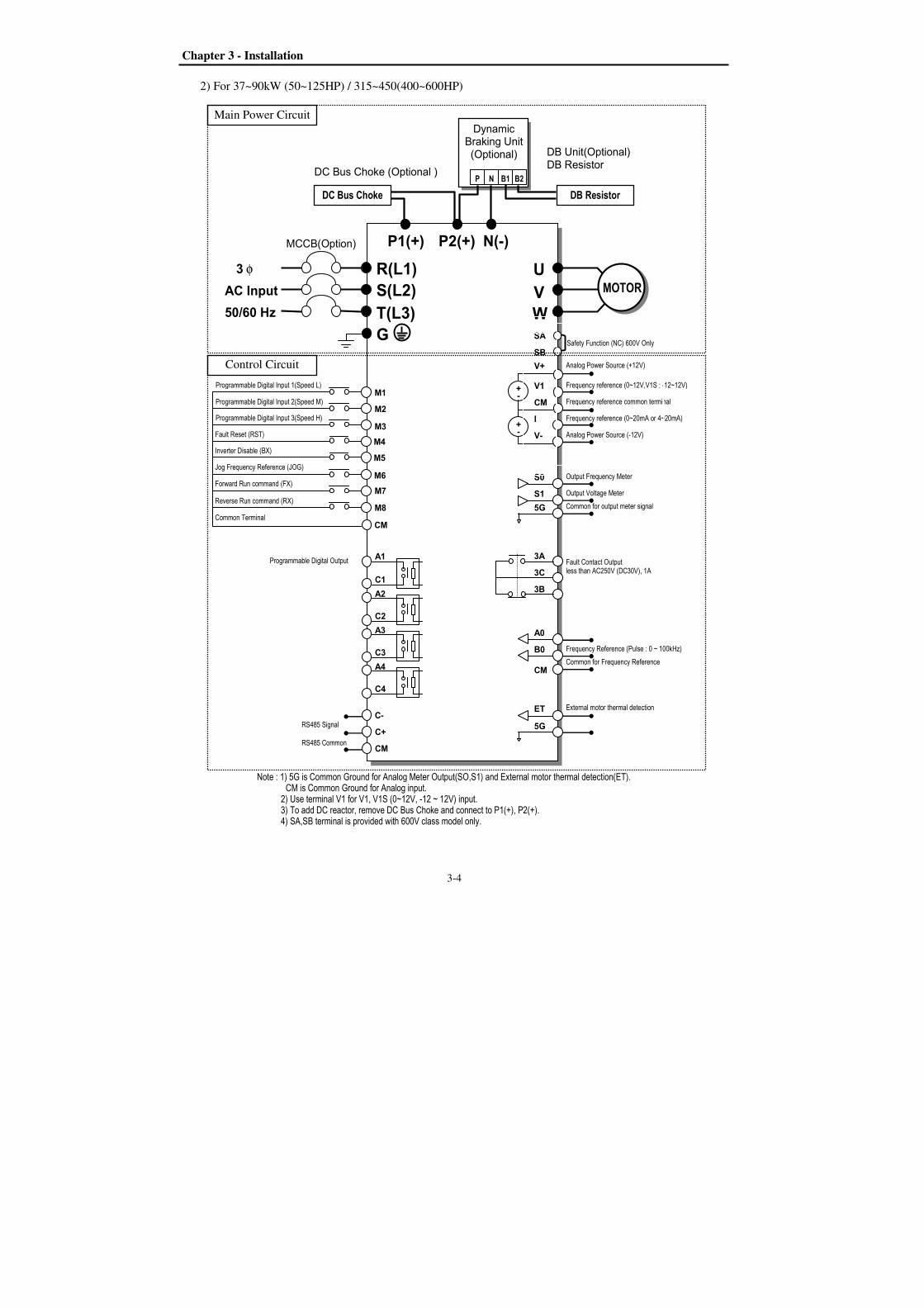
2) For 37~90kW (50~125HP) / 315~450(400~600HP)
AC Input
50/60 Hz
U
V
W
G
R(L1)
S(L2)
T(L3)
N(-)
DB Unit(Optional)
DB Resistor
φ 3
MCCB(Option)
M1
M2
M3
M4
M6
M8
M7
MOTOR
Programmable Digital Input 1(Speed L)
Programmable Digital Input 2(Speed M)
Programmable Digital Input 3(Speed H)
Fault Reset (RST)
Jog Frequency Reference (JOG)
Forward Run command (FX)
Reverse Run command (RX)
Common Terminal
Fault Contact Output less than AC250V (DC30V), 1A
P2(+)
P1(+)
DC Bus Choke (Optional )
Dynamic Braking Unit (Optional)
P N B1 B2
DC Bus Choke DB Resistor
M5 Inverter Disable (BX)
V+
V1
CM
V-
I
Analog Power Source (+12V)
+ -
+ -
Analog Power Source (-12V)
Frequency reference (0~20mA or 4~20mA)
Frequency reference (0~12V,V1S : -12~12V)
Frequency reference common terminal
S1
S0
5G
Output Frequency Meter Output Voltage Meter Common for output meter signal
3A
3C
3B
CM
B0
A0
Common for Frequency Reference
Frequency Reference (Pulse : 0 ~ 100kHz)
5G
ET External motor thermal detection
A1
C1
A2
C2
A3
C3
A4
C4
C-
C+
CM
RS485 Signal
RS485 Common
CM
Note : 1) 5G is Common Ground for Analog Meter Output(SO,S1) and External motor thermal detection(ET). CM is Common Ground for Analog input. 2) Use terminal V1 for V1, V1S (0~12V, -12 ~ 12V) input. 3) To add DC reactor, remove DC Bus Choke and connect to P1(+), P2(+).
4) SA,SB terminal is provided with 600V class model only.
Programmable Digital Output
SA
SB Safety Function (NC) 600V Only
Main Power Circuit
Control Circuit

Chapter 3 - Installation
3-5
3) For 110~280kW (150~350HP)
AC Input
50/60 Hz
U
V
W
G
R(L1)
S(L2)
T(L3)
DB Unit(Optional)
DB Resistor
φ 3
M1
M2
M3
M4
M6
M8
M7
MOTOR
Programmable Digital Input 1(Speed L)
Programmable Digital Input 2(Speed M)
Programmable Digital Input 3(Speed H)
Fault Reset (RST)
Jog Frequency Reference (JOG)
Forward Run command (FX)
Reverse Run command (RX)
Common Terminal
Fault Contact Output less than AC250V (DC30V), 1A
P2(+)
Dynamic Braking Unit (Optional)
P N B1 B2
DB Resistor
M5 Inverter Disable (BX)
V+
V1
CM
V-
I
Analog Power Source (+12V)
+ -
+ -
Analog Power Source (-12V)
Frequency reference (0~20mA or 4~20mA)
Frequency reference (0~12V,V1S : -12~12V)
Frequency reference common terminal
S1
S0
5G
Output Frequency Meter Output Voltage Meter Common for output meter signal
3A
3C
3B
CM
B0
A0
Common for Frequency Reference
Frequency Reference (Pulse : 0 ~ 100kHz)
5G
ET External motor thermal detection
A1
C1
A2
C2
A3
C3
A4
C4
C-
C+
CM
RS485 Signal
RS485 Common
CM
Note : 1) 5G is Common Ground for Analog Meter Output(SO,S1) and External motor thermal detection(ET). CM is Comon Ground for Analog Input. 2) Use terminal V1 for V1, V1S (0~12V, -12 ~ 12V) input. 3) DC Reactor is built basically in the inverters for 110~280kW(150~350HP).
4) SA,SB terminal is provided with 600V class model only.
Programmable Digital Output
DC Reactor(Built-in) )))) SA
SB Safety Function (NC) 600V Only
Main Power Circuit
Control Circuit
Chapter 3 - Installation
3-6
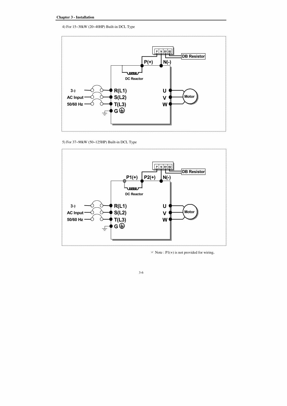
4) For 15~30kW (20~40HP) Built-in DCL Type
AC Input
50/60 Hz
U
V
W
G
R(L1)
S(L2)
T(L3)
N(-)
φ 3
Motor
P(+)
P N B1 B2
DB Resistor
DC Reactor
5) For 37~90kW (50~125HP) Built-in DCL Type
AC Input
50/60 Hz
U
V
W
G
R(L1)
S(L2)
T(L3)
φ 3
Motor
P2(+)
P1(+)
P N B1 B2
DB Resistor
DC Reactor
N(-)
Note : P1(+) is not provided for wiring.
Chapter 3 - Installation
3-7
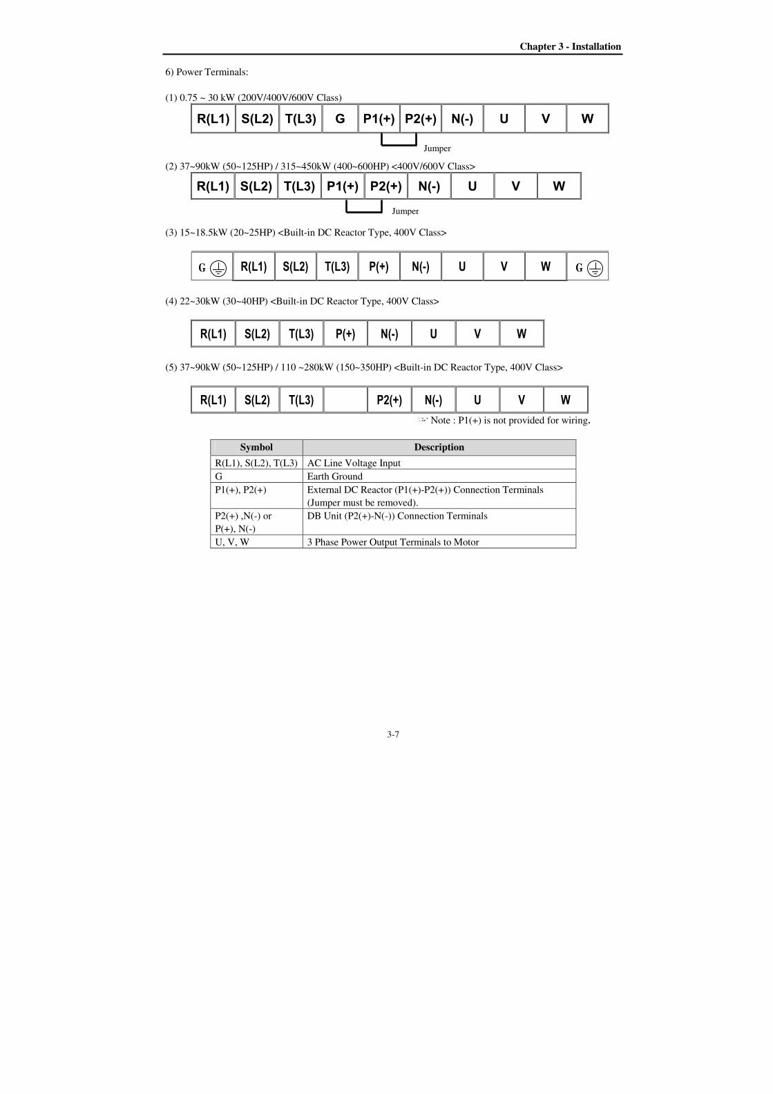
6) Power Terminals:
(1) 0.75 ~ 30 kW (200V/400V/600V Class)
R(L1) S(L2) T(L3) G P1(+) P2(+) N(-) U V W
(2) 37~90kW (50~125HP) / 315~450kW (400~600HP) <400V/600V Class>
R(L1) S(L2) T(L3) P1(+) P2(+) N(-) U V W
(3) 15~18.5kW (20~25HP) <Built-in DC Reactor Type, 400V Class>
R(L1) S(L2) T(L3) P(+) N(-) U V W
(4) 22~30kW (30~40HP) <Built-in DC Reactor Type, 400V Class>
R(L1) S(L2) T(L3) P(+) N(-) U V W
(5) 37~90kW (50~125HP) / 110 ~280kW (150~350HP) <Built-in DC Reactor Type, 400V Class>
R(L1) S(L2) T(L3) P2(+) N(-) U V W Note : P1(+) is not provided for wiring.
Symbol Description
R(L1), S(L2), T(L3) AC Line Voltage Input
G Earth Ground
P1(+), P2(+) External DC Reactor (P1(+)-P2(+)) Connection Terminals
(Jumper must be removed).
P2(+) ,N(-) or
P(+), N(-)
DB Unit (P2(+)-N(-)) Connection Terminals
U, V, W 3 Phase Power Output Terminals to Motor
Jumper
Jumper
G G
Chapter 3 - Installation
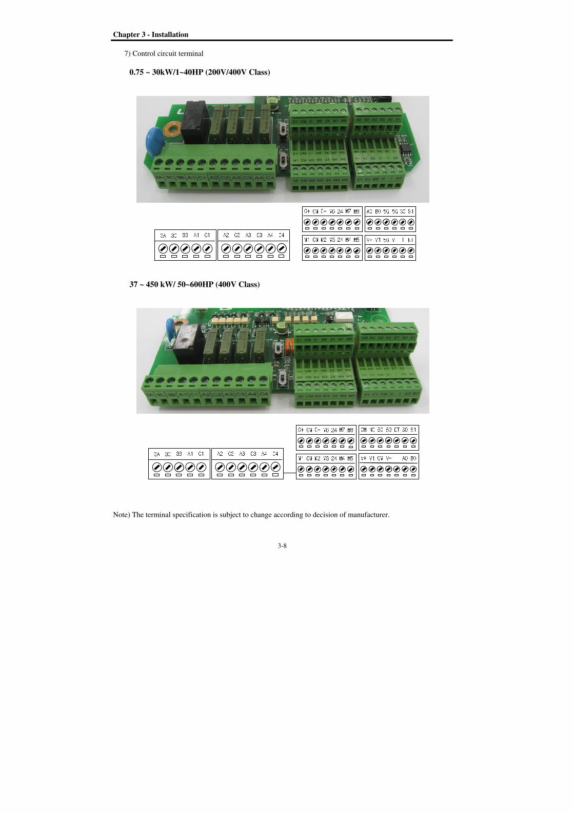
7) Control circuit terminal
0.75 ~ 30kW/1
37 ~ 450 kW/ 50~
Note) The terminal specification is subject to change according to decision of manufacturer.
3A 3C
3A 3C 3B
Installation
3-
) Control circuit terminal
1~40HP (200V/400V Class)
50~600HP (400V Class)
The terminal specification is subject to change according to decision of manufacturer.
3B A1 C1 A2 C2 A3 C3 A4 C4
3B A1 C1 A2 C2 A3 C3 A4 C4 -8
The terminal specification is subject to change according to decision of manufacturer.
A0 B0 5GV+ V1 5GC+ CM C- M6 24 M7 M8 M1 CM M2 M3 24 M4 M5 C4
C+ CM C- M6 24 M7 M8 M1 CM M2 M3 24 M4 M5 CM NC 5G V+ V1 CM
The terminal specification is subject to change according to decision of manufacturer.
5G 5G S0 S1 5G V- I NT
5G ET S0 S1 V- I A0 B0
Chapter 3 - Installation
3-9
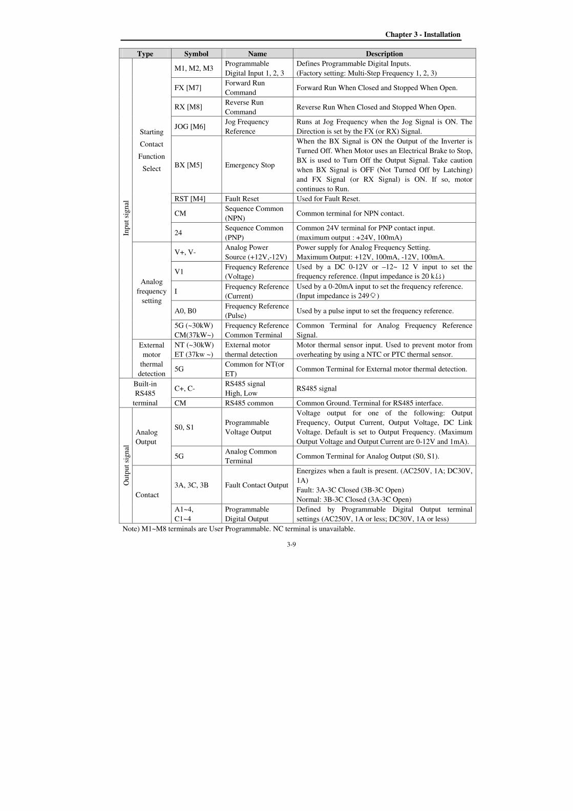
Type Symbol Name Description
Inp
ut
sig
nal
Starting
Contact
Function
Select
M1, M2, M3 Programmable
Digital Input 1, 2, 3
Defines Programmable Digital Inputs.
(Factory setting: Multi-Step Frequency 1, 2, 3)
FX [M7] Forward Run
Command Forward Run When Closed and Stopped When Open.
RX [M8] Reverse Run
Command Reverse Run When Closed and Stopped When Open.
JOG [M6] Jog Frequency
Reference
Runs at Jog Frequency when the Jog Signal is ON. The
Direction is set by the FX (or RX) Signal.
BX [M5] Emergency Stop
When the BX Signal is ON the Output of the Inverter is
Turned Off. When Motor uses an Electrical Brake to Stop,
BX is used to Turn Off the Output Signal. Take caution
when BX Signal is OFF (Not Turned Off by Latching)
and FX Signal (or RX Signal) is ON. If so, motor
continues to Run.
RST [M4] Fault Reset Used for Fault Reset.
CM Sequence Common
(NPN) Common terminal for NPN contact.
24 Sequence Common
(PNP)
Common 24V terminal for PNP contact input.
(maximum output : +24V, 100mA)
Analog
frequency
setting
V+, V- Analog Power
Source (+12V,-12V)
Power supply for Analog Frequency Setting.
Maximum Output: +12V, 100mA, -12V, 100mA.
V1 Frequency Reference
(Voltage)
Used by a DC 0-12V or –12~ 12 V input to set the
frequency reference. (Input impedance is 20 kΩ)
I Frequency Reference
(Current)
Used by a 0-20mA input to set the frequency reference.
(Input impedance is 249Ω)
A0, B0 Frequency Reference
(Pulse) Used by a pulse input to set the frequency reference.
5G (~30kW)
CM(37kW~)
Frequency Reference
Common Terminal
Common Terminal for Analog Frequency Reference
Signal.
External
motor
thermal
detection
NT (~30kW)
ET (37kw ~)
External motor
thermal detection
Motor thermal sensor input. Used to prevent motor from
overheating by using a NTC or PTC thermal sensor.
5G Common for NT(or
ET) Common Terminal for External motor thermal detection.
Built-in
RS485
terminal
C+, C- RS485 signal
High, Low RS485 signal
CM RS485 common Common Ground. Terminal for RS485 interface.
Ou
tpu
t si
gn
al
Analog
Output
S0, S1 Programmable
Voltage Output
Voltage output for one of the following: Output
Frequency, Output Current, Output Voltage, DC Link
Voltage. Default is set to Output Frequency. (Maximum
Output Voltage and Output Current are 0-12V and 1mA).
5G Analog Common
Terminal Common Terminal for Analog Output (S0, S1).
Contact
3A, 3C, 3B Fault Contact Output
Energizes when a fault is present. (AC250V, 1A; DC30V,
1A)
Fault: 3A-3C Closed (3B-3C Open)
Normal: 3B-3C Closed (3A-3C Open)
A1~4,
C1~4
Programmable
Digital Output
Defined by Programmable Digital Output terminal
settings (AC250V, 1A or less; DC30V, 1A or less)
Note) M1~M8 terminals are User Programmable. NC terminal is unavailable.
Chapter 3 - Installation
3.2.2 Wiring power terminals
Wiring Precautions
1) The internal circuits of the inverter
output terminals (U, V, W).
2) Use ring terminals with insulated caps when wiring the input power and motor wiring.
3) Do not leave wire fragments inside the inverter. Wire fragments can cause faults, breakdowns, and
malfunctions.
4) For input and output, use wires with sufficient size to ensure voltage drop of less than 2%.
5) Motor torque may drop of operating at low frequencies and a long wire run between inverter and motor.
6) The cable length
capacitance between
output side may malfunction. (But for products of
(164ft) when carrier frequency is more than 10 kHz
7) The main circuit of the inverter contains high frequency noise, and can hinder communication
equipment near the inverter. To reduce noise, install line noise filters on the input side of the inverter.
8) Do not use power factor capacitor, surge killers
so may damage these component
9) Always check whether the LCD and the charge lamp for the power terminal
terminals. The charge capacitor may hold high
prevent the possibility of personal injury.
10) Do not connect with MC at output pare of inverter and make MC On/Off during operation.
the Trip or damage of inverter
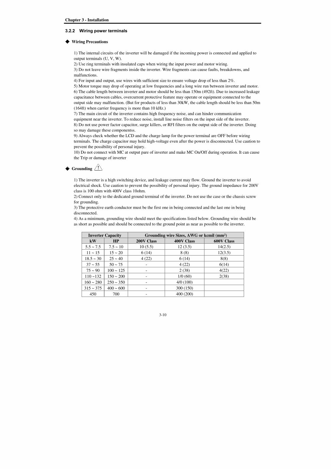
Grounding
1) The inverter is a
electrical shock. Use caution to prevent the possibility of personal injury. The ground impedance for 200V
class is 100 ohm with 400V class 10ohm.
2) Connect only to the dedi
for grounding.
3) The protective earth conductor must be the first one in being connected and the last one in being
disconnected.
4) As a minimum, grounding wire should meet th
as short as possible and should be connected to the ground point as near as
Inverter Capacity
kW
5.5 ~ 7.5
11 ~ 15
18.5 ~ 30
37 ~ 55
75 ~ 90
110 ~132
160 ~ 280
315 ~ 375
450
Installation
3-10
Wiring power terminals
Wiring Precautions
1) The internal circuits of the inverter will be damaged if the
output terminals (U, V, W).
2) Use ring terminals with insulated caps when wiring the input power and motor wiring.
3) Do not leave wire fragments inside the inverter. Wire fragments can cause faults, breakdowns, and
4) For input and output, use wires with sufficient size to ensure voltage drop of less than 2%.
5) Motor torque may drop of operating at low frequencies and a long wire run between inverter and motor.
length between inverter and motor should be less than
capacitance between cables, overcurrent protective feature may operate or equipment connected to the
output side may malfunction. (But for products of less
when carrier frequency is more than 10 kHz
7) The main circuit of the inverter contains high frequency noise, and can hinder communication
equipment near the inverter. To reduce noise, install line noise filters on the input side of the inverter.
8) Do not use power factor capacitor, surge killers, or RFI filters on the output side of the inverter. Doing
so may damage these componentss.
9) Always check whether the LCD and the charge lamp for the power terminal
terminals. The charge capacitor may hold high-voltage even after th
prevent the possibility of personal injury.
10) Do not connect with MC at output pare of inverter and make MC On/Off during operation.
the Trip or damage of inverter
The inverter is a high switching device, and leakage current may flow. Ground the inverter to avoid
electrical shock. Use caution to prevent the possibility of personal injury. The ground impedance for 200V
class is 100 ohm with 400V class 10ohm.
Connect only to the dedicated ground terminal of the inverter. Do not use the case or the chassis screw
The protective earth conductor must be the first one in being connected and the last one in being
As a minimum, grounding wire should meet the specifications listed below. Grounding wire
as short as possible and should be connected to the ground point as near as
Inverter Capacity Grounding wire Sizes, AWG or kcmil (
HP 200V Class
7.5 ~ 10 10 (5.5)
15 ~ 20 6 (14)
30 25 ~ 40 4 (22)
50 ~ 75 -
100 ~ 125 -
150 ~ 200 -
250 ~ 350 -
400 ~ 600 -
700 -
10
damaged if the incoming power is connected and applied to
2) Use ring terminals with insulated caps when wiring the input power and motor wiring.
3) Do not leave wire fragments inside the inverter. Wire fragments can cause faults, breakdowns, and
4) For input and output, use wires with sufficient size to ensure voltage drop of less than 2%.
5) Motor torque may drop of operating at low frequencies and a long wire run between inverter and motor.
should be less than 150m (492ft). Due to increased leakage
s, overcurrent protective feature may operate or equipment connected to the
less than 30kW, the cable length should be less than 50m
when carrier frequency is more than 10 kHz.)
7) The main circuit of the inverter contains high frequency noise, and can hinder communication
equipment near the inverter. To reduce noise, install line noise filters on the input side of the inverter.
, or RFI filters on the output side of the inverter. Doing
9) Always check whether the LCD and the charge lamp for the power terminal are OFF before wiring
voltage even after the power is disconnected. Use caution to
10) Do not connect with MC at output pare of inverter and make MC On/Off during operation.
high switching device, and leakage current may flow. Ground the inverter to avoid
electrical shock. Use caution to prevent the possibility of personal injury. The ground impedance for 200V
cated ground terminal of the inverter. Do not use the case or the chassis screw
The protective earth conductor must be the first one in being connected and the last one in being
e specifications listed below. Grounding wire
as short as possible and should be connected to the ground point as near as possible to the inverter.
Grounding wire Sizes, AWG or kcmil (mm²
400V Class 600V
12 (3.5) 14(2.5)
8 (8) 12(3.5)
6 (14) 8(8)
4 (22) 6(14)
2 (38) 4(22)
1/0 (60) 2(38)
4/0 (100)
300 (150)
400 (200)
power is connected and applied to
2) Use ring terminals with insulated caps when wiring the input power and motor wiring.
3) Do not leave wire fragments inside the inverter. Wire fragments can cause faults, breakdowns, and
4) For input and output, use wires with sufficient size to ensure voltage drop of less than 2%.
5) Motor torque may drop of operating at low frequencies and a long wire run between inverter and motor.
ft). Due to increased leakage
s, overcurrent protective feature may operate or equipment connected to the
length should be less than 50m
7) The main circuit of the inverter contains high frequency noise, and can hinder communication
equipment near the inverter. To reduce noise, install line noise filters on the input side of the inverter.
, or RFI filters on the output side of the inverter. Doing
OFF before wiring
e power is disconnected. Use caution to
10) Do not connect with MC at output pare of inverter and make MC On/Off during operation. It can cause
high switching device, and leakage current may flow. Ground the inverter to avoid
electrical shock. Use caution to prevent the possibility of personal injury. The ground impedance for 200V
cated ground terminal of the inverter. Do not use the case or the chassis screw
The protective earth conductor must be the first one in being connected and the last one in being
e specifications listed below. Grounding wire should be
possible to the inverter.
mm²)
600V Class
14(2.5)
12(3.5)
8(8)
6(14)
4(22)
2(38)
Chapter 3 - Installation
3-11
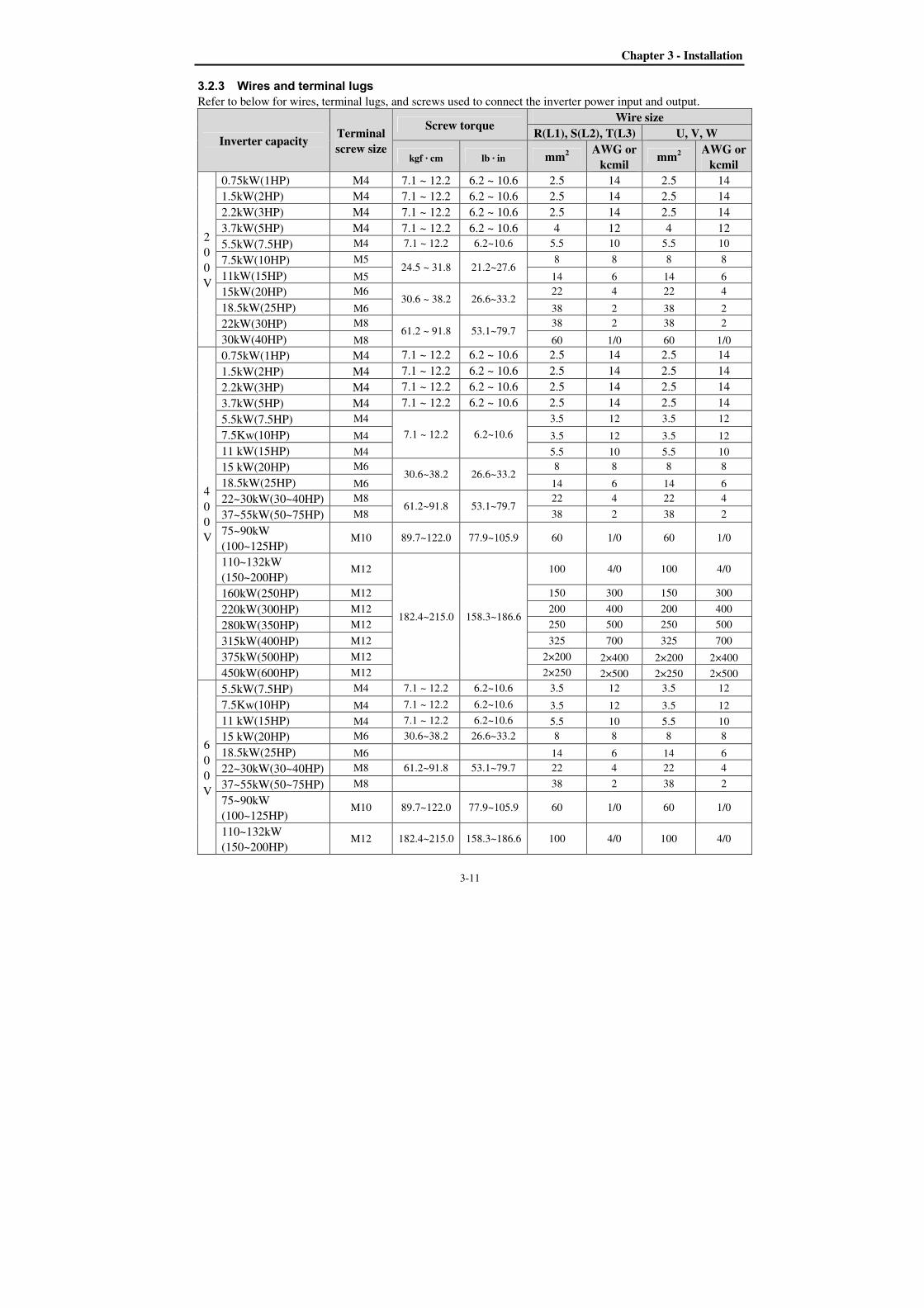
3.2.3 Wires and terminal lugs
Refer to below for wires, terminal lugs, and screws used to connect the inverter power input and output.
Inverter capacity Terminal
screw size
Screw torque Wire size
R(L1), S(L2), T(L3) U, V, W
kgf · cm lb · in mm2 AWG or
kcmil mm2
AWG or
kcmil
2
0
0
V
0.75kW(1HP) M4 7.1 ~ 12.2 6.2 ~ 10.6 2.5 14 2.5 14
1.5kW(2HP) M4 7.1 ~ 12.2 6.2 ~ 10.6 2.5 14 2.5 14
2.2kW(3HP) M4 7.1 ~ 12.2 6.2 ~ 10.6 2.5 14 2.5 14
3.7kW(5HP) M4 7.1 ~ 12.2 6.2 ~ 10.6 4 12 4 12
5.5kW(7.5HP) M4 7.1 ~ 12.2 6.2~10.6 5.5 10 5.5 10
7.5kW(10HP) M5 24.5 ~ 31.8 21.2~27.6
8 8 8 8
11kW(15HP) M5 14 6 14 6
15kW(20HP) M6 30.6 ~ 38.2 26.6~33.2
22 4 22 4
18.5kW(25HP) M6 38 2 38 2
22kW(30HP) M8 61.2 ~ 91.8 53.1~79.7
38 2 38 2
30kW(40HP) M8 60 1/0 60 1/0
4
0
0
V
0.75kW(1HP) M4 7.1 ~ 12.2 6.2 ~ 10.6 2.5 14 2.5 14
1.5kW(2HP) M4 7.1 ~ 12.2 6.2 ~ 10.6 2.5 14 2.5 14
2.2kW(3HP) M4 7.1 ~ 12.2 6.2 ~ 10.6 2.5 14 2.5 14
3.7kW(5HP) M4 7.1 ~ 12.2 6.2 ~ 10.6 2.5 14 2.5 14
5.5kW(7.5HP) M4
7.1 ~ 12.2 6.2~10.6
3.5 12 3.5 12
7.5Kw(10HP) M4 3.5 12 3.5 12
11 kW(15HP) M4 5.5 10 5.5 10
15 kW(20HP) M6 30.6~38.2 26.6~33.2
8 8 8 8
18.5kW(25HP) M6 14 6 14 6
22~30kW(30~40HP) M8 61.2~91.8 53.1~79.7
22 4 22 4
37~55kW(50~75HP) M8 38 2 38 2
75~90kW
(100~125HP) M10 89.7~122.0 77.9~105.9 60 1/0 60 1/0
110~132kW
(150~200HP) M12
182.4~215.0 158.3~186.6
100 4/0 100 4/0
160kW(250HP) M12 150 300 150 300
220kW(300HP) M12 200 400 200 400
280kW(350HP) M12 250 500 250 500
315kW(400HP) M12 325 700 325 700
375kW(500HP) M12 2×200 2×400 2×200 2×400
450kW(600HP) M12 2×250 2×500 2×250 2×500
6
0
0
V
5.5kW(7.5HP) M4 7.1 ~ 12.2 6.2~10.6 3.5 12 3.5 12
7.5Kw(10HP) M4 7.1 ~ 12.2 6.2~10.6 3.5 12 3.5 12
11 kW(15HP) M4 7.1 ~ 12.2 6.2~10.6 5.5 10 5.5 10
15 kW(20HP) M6 30.6~38.2 26.6~33.2 8 8 8 8
18.5kW(25HP) M6 14 6 14 6
22~30kW(30~40HP) M8 61.2~91.8 53.1~79.7 22 4 22 4
37~55kW(50~75HP) M8 38 2 38 2
75~90kW
(100~125HP) M10 89.7~122.0 77.9~105.9 60 1/0 60 1/0
110~132kW
(150~200HP) M12 182.4~215.0 158.3~186.6 100 4/0 100 4/0

Chapter 3 - Installation
3-12
* Apply the rated torque to terminal screws.
* Loose screws can cause of short circuit or malfunction. Tightening the screw too much can damage the
terminals and cause a short circuit or malfunction.
* Use copper wires only with 600V, 75 ratings. For 7.5~11kW 240V type inverters, R(L1), S(L2), T(L3) and
U, V, W terminals are only for use with insulated ring type connector.
Power and Motor Connection Example (5.5~30kW inverters)
R(L1) S(L2) T(L3) G P1(+) P2(+) N(-) U V W
3.2.4 Control circuit wiring
1) Wiring Precautions
CM and 5G terminals are insulated each other. Do not connect these terminals together or to the power
ground.
Use shielded wires or twisted wires for control circuit wiring, and separate these wires from the main power
circuits and other high voltage circuits (200V relay sequence circuit).
It is recommended to use the cables of 0.0804mm2 (28 AWG) ~ 1.25mm2 (16 AWG) for TER1, TER2
control terminals and the cables of 0.33mm2 (22 AWG) ~ 2.0mm2 (14 AWG) for TER3, TER4 control
terminals.
2) Control terminal layout
Power supply must be connected to the R(L1), S(L2), and T(L3) terminals. Connecting it to the U, V, and
W terminals causes internal
damages to the inverter.
Arranging the phase sequence is
not necessary.
Motor should be connected to the U, V, and W terminals. If the forward command (FX) is on, the
motor should rotate counter clockwise when
viewed from the load side of the motor. If
the motor rotates in the reverse, switch the U
and V terminals.
Ground
Ground
Forward
A0 B0 5G 5G S0 S1 V+ V1 5G V- I NT C+ CM C- M6 24 M7 M8 M1 CM M2 M3 24 M4 M5 3A 3C 3B A1 C1 A2 C2 A3 C3 A4 C4 TER4 TER3 TER2 TER1
0.33mm2 (22 AWG) ~ 2.0mm
2 (14 AWG) 0.0804mm2 (28 AWG) ~ 1.25mm2 (16 AWG)
Chapter 3 - Installation
3-13
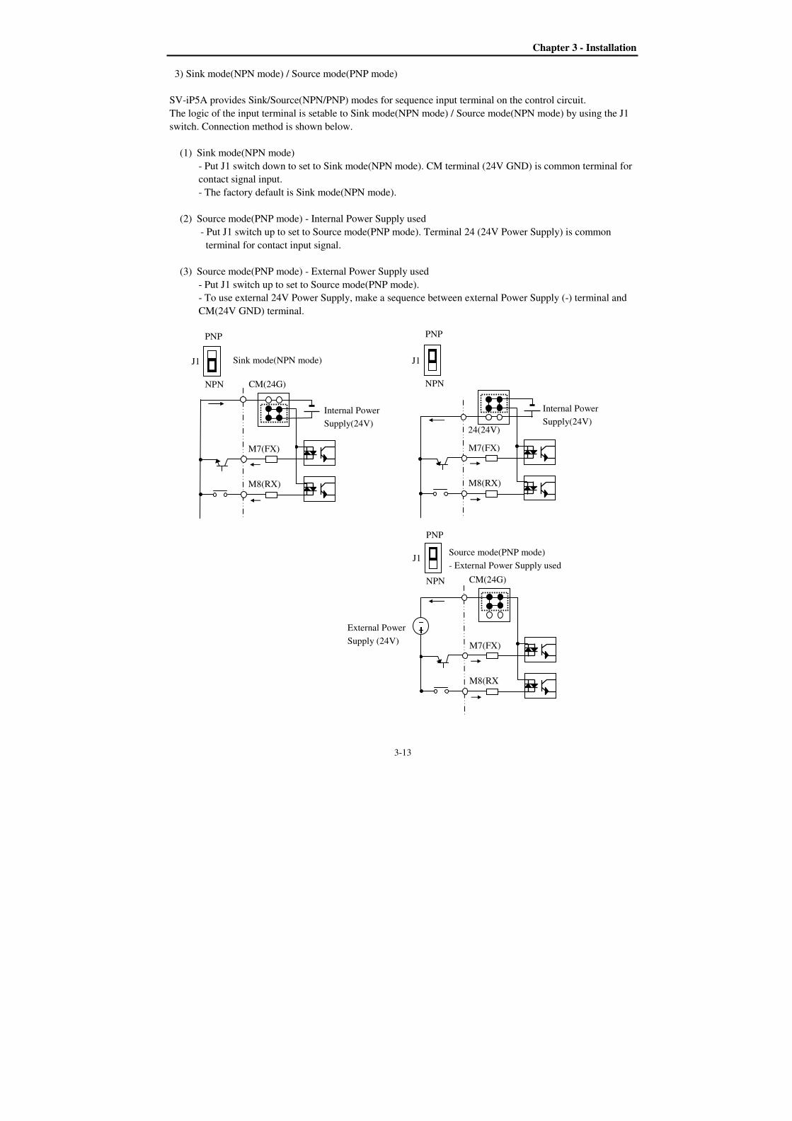
3) Sink mode(NPN mode) / Source mode(PNP mode)
SV-iP5A provides Sink/Source(NPN/PNP) modes for sequence input terminal on the control circuit.
The logic of the input terminal is setable to Sink mode(NPN mode) / Source mode(NPN mode) by using the J1
switch. Connection method is shown below.
(1) Sink mode(NPN mode)
- Put J1 switch down to set to Sink mode(NPN mode). CM terminal (24V GND) is common terminal for
contact signal input.
- The factory default is Sink mode(NPN mode).
(2) Source mode(PNP mode) - Internal Power Supply used
- Put J1 switch up to set to Source mode(PNP mode). Terminal 24 (24V Power Supply) is common
terminal for contact input signal.
(3) Source mode(PNP mode) - External Power Supply used
- Put J1 switch up to set to Source mode(PNP mode).
- To use external 24V Power Supply, make a sequence between external Power Supply (-) terminal and
CM(24V GND) terminal.
Internal Power
Supply(24V)
CM(24G)
M7(FX)
M8(RX)
J1
NPN
PNP
Sink mode(NPN mode)
External Power
Supply (24V) CM(24G)
M7(FX)
M8(RX
J1
NPN
PNP
---- ++++ Source mode(PNP mode)
- External Power Supply used
Internal Power
Supply(24V) 24(24V)
M7(FX)
M8(RX)
J1
NPN
PNP
Chapter 3 - Installation
3-14
3.2.5 RS485 circuit wiring
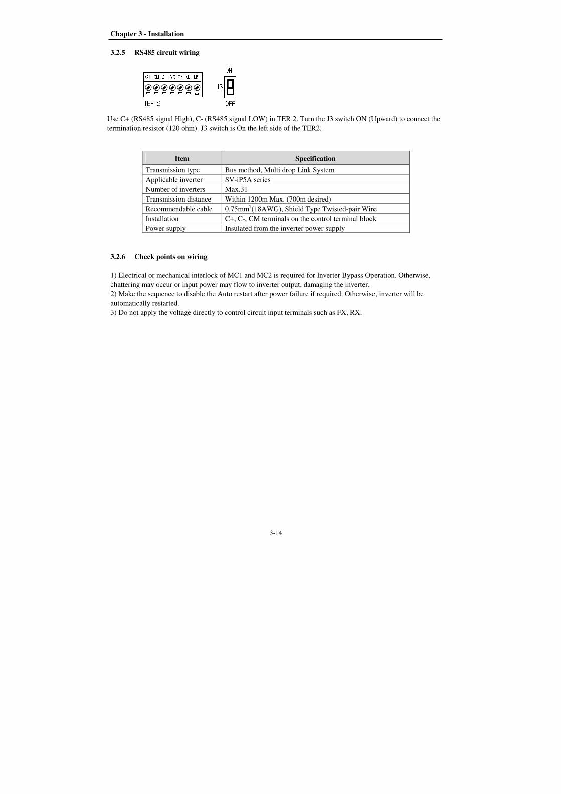
Use C+ (RS485 signal High), C- (RS485 signal LOW) in TER 2. Turn the J3 switch ON (Upward) to connect the
termination resistor (120 ohm). J3 switch is On the left side of the TER2.
Item Specification
Transmission type Bus method, Multi drop Link System
Applicable inverter SV-iP5A series
Number of inverters Max.31
Transmission distance Within 1200m Max. (700m desired)
Recommendable cable 0.75mm2(18AWG), Shield Type Twisted-pair Wire
Installation C+, C-, CM terminals on the control terminal block
Power supply Insulated from the inverter power supply
3.2.6 Check points on wiring
1) Electrical or mechanical interlock of MC1 and MC2 is required for Inverter Bypass Operation. Otherwise,
chattering may occur or input power may flow to inverter output, damaging the inverter.
2) Make the sequence to disable the Auto restart after power failure if required. Otherwise, inverter will be
automatically restarted.
3) Do not apply the voltage directly to control circuit input terminals such as FX, RX.
C+ CM C- M6 24 M7 M8 TER 2 J3 OFF ON

4-1
CHAPTER 4 - OPERATION
4.1 Programming Keypads
4.1.1 LCD Keypad
LCD keypad can display up to 32 alphanumeric characters, and various settings can be checked directly from
the display. The following is an illustration of the keypad.
32 character, background light, LCD display. The background tone is adjustable.
The Mode Button moves you through the seven program groups: DRV [Mode]
FU1 [ENT]DRV
The Program Button is used to go into programming mode to
change data.
The Enter Button is used to enter changed data within a parameter. DRV [ENT] APP [MODE] DRV
[SHIFT] This button is used to move cursor across display in programming mode. [ESC] This button is used to move the program code to DRV 00 form any program code.
Reverse Run Button The Reverse Run LED blinks when the drive Accels or Decels.
Forward Run Button The Forward Run LED blinks when the drive Accels or Decels.
Stop Button is used to stop the drive from running. (It has the priority over the parameter setting.) Reset Button is used to reset Faults. LED blinks when there is a fault.

Chapter 4 - Operation
4-2
1) Keypad dimension
Unit : mm
2) Detail description
(1) LCD Keypad Display
DRVT/K 0.0 A00 STP 0.00 Hz
Displays Description
1) Parameter Group Displays the parameter group. There are DRV, FU1, FU2, I/O, EXT, COM, APP
groups.
2) Run/Stop Source Displays the source of motor Run and Stop
K: Run/Stop using FWD, REV buttons on keypad
T: Run/Stop using control terminal input FX, RX
R: Run/Stop using RS485
O: Run/Stop via option board
3) Frequency Setting
Source
Displays the source of command frequency setting
K: Frequency setting using keypad
V: Frequency setting using V1 (0 ~12V) or V1 + I terminal
W: Analog frequency reference (V1S: -12 ~ 12V)
I: Frequency setting using I (4 ~ 20mA) terminal
P: Frequency setting using Pulse input
R: Frequency setting using RS485
U: Up terminal input when Up/Down operation is selected
2) Run/Stop Source 3) Frequency Setting Source
4) Output Current
7) Drive Output Frequency During Run,
Command Frequency During Stop 6) Operating Status
5) Parameter Code
1) Parameter group

Chapter 4 – Operation
4-3
Displays Description
D: Down terminal input when Up/Down operation is selected
S: Stop status when Up/Down operation is selected
O: Frequency setting via Option board
X: Frequency setting via Sub board
J: Jog terminal input
1 ~ 15: Step frequency operation (except Jog)
4) Output Current Displays the Output Current during operation.
5) Parameter Code Displays the code of a group. Use the (Up), (Down) key to move through
0~99 codes.
6) Operating Status Displays the operation information.
STP: Stop Status
FWD: During Forward operation
REV: During Reverse operation
DCB: During DC Braking
LOP: Loss of Reference from Option Board (DPRAM fault)
LOR: Loss of Reference from Option Board (Communication network fault)
LOV: Loss of Analog Frequency Reference (V1: 0~12V, -10~12V)
LOI: Loss of Analog Frequency Reference (I: 4~20mA)
LOS: Loss of Reference from Sub-Board
7) Inverter Output
Frequency/ Command
Frequency
Displays the Output Frequency during run.
Displays the Command Frequency during stop.
4.1.2 Parameter setting and changing
1) Press [MODE] key until the desired parameter group is displayed.
2) Press [] or [] keys to move to the desired parameter code. If you know the desired parameter code,
you can set the code number of each parameter group in “Jump code”, except DRV group.
3) Press [PROG] key to go into the programming mode, the cursor starts blinking.
4) Press [SHIFT/ESC] key to move the cursor to the desired digit.
5) Press [] or [] keys to change the data.
6) Press [ENT] key to enter the data. The cursor stops blinking.
Note: Data cannot be changed when 1) the parameter is not adjustable during the inverter is running (see the
function list), or 2) Parameter Lock function FU2-94 [Parameter Lock] is activated.
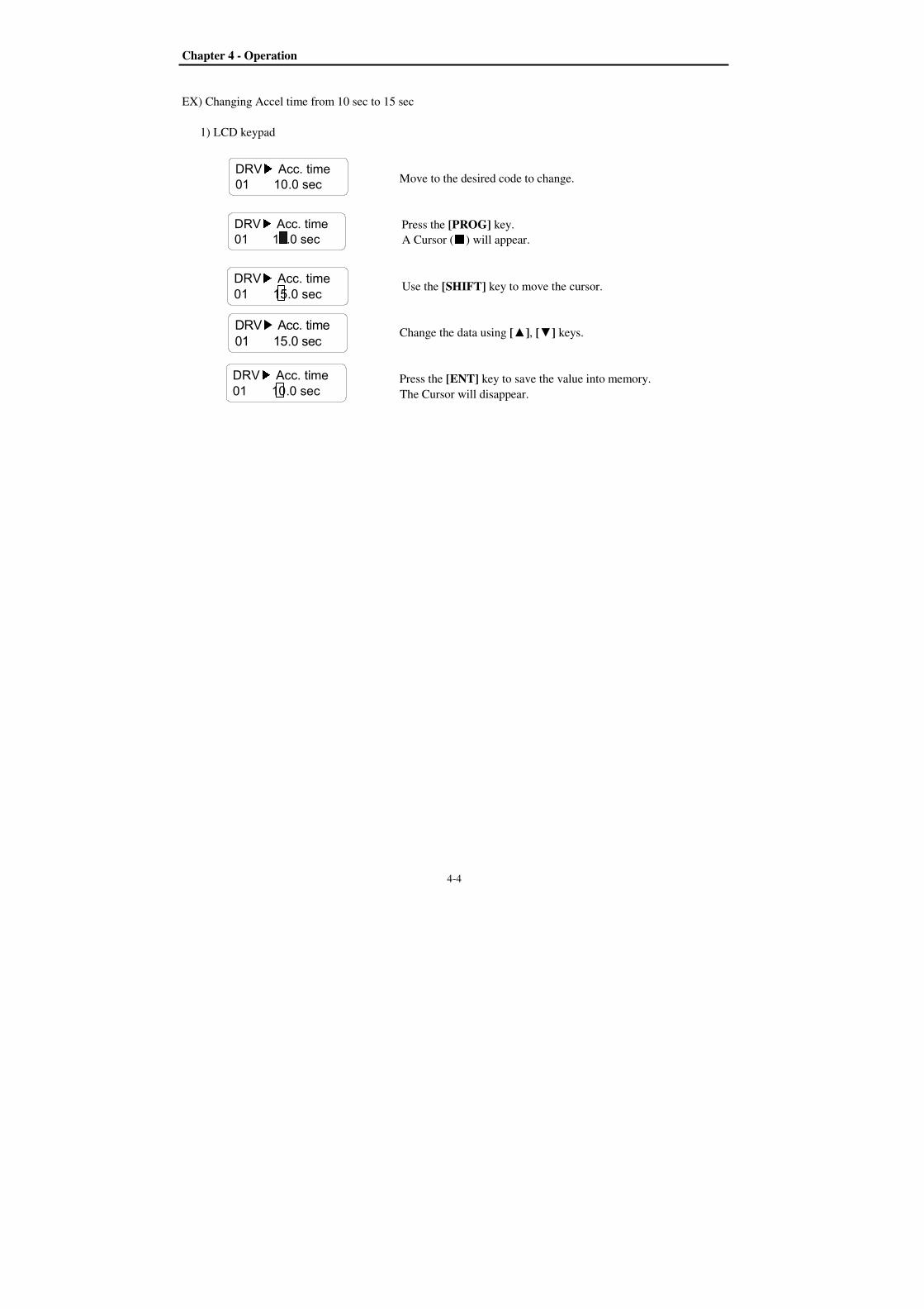
Chapter 4 - Operation
4-4
DRV Acc. time01 10.0 sec
DRV Acc. time01 10.0 sec
DRV Acc. time01 10.0 sec
DRV Acc. time01 15.0 sec
DRV Acc. time01 15.0 sec
EX) Changing Accel time from 10 sec to 15 sec
1) LCD keypad
Move to the desired code to change.
Press the [PROG] key.
A Cursor () will appear.
Use the [SHIFT] key to move the cursor.
Change the data using [], [] keys.
Press the [ENT] key to save the value into memory.
The Cursor will disappear.

Chapter 4 – Operation
4-5
4.1.3 Parameter groups
The iP5A series inverter has 5 parameter groups separated according to their applications as indicated in the
following table.
The iP5A series inverter provides two kinds of keypad. One is 32-character alphanumeric LCD keypad and the
other is 7-Segment LED keypad.
Parameter Group
LCD Keypad Description
Drive Group DRV Command Frequency, Accel/Decel Time etc.
Basic function Parameters
Function 1 Group FU1 Max. Frequency, Amount of Torque Boost etc.
Parameters related to basic functions
Function 2 Group FU2 Frequency Jumps, Max/Min Frequency Limit etc.
Basic Application Parameters
Input / Output
Group I/O
Programmable Digital Input/Output Terminal
Setting, Auto Operation etc. Parameters needed for
Sequence Operation
Application
Group APP
PID, MMC (Multi-Motor Control), 2nd
motor
operation etc. Parameters related to Application
function
Refer to the function descriptions for detailed description of each group.

Chapter 4 - Operation
4-6
1) Parameter Navigation (LCD Keypad)
The parameter group moves directly to DRV group by pressing [SHIFT] key in any parameter code.
Drive Group FU1 Group FU2 Group I/O Group
Note: This figure shows the group and code navigation through LCD display keypad. It can be different
from the actual display due to the group addition or code change.
DRVT/K 0.0 A
00 STP 60.00Hz
FU1 Jump code
00 1
FU2 Jump code
00 30
MODE
FU1Run prohibit
03 None
FU2 Last trip-1
01 -------
I/O V1 filter
01 10 ms
DRV Dec. time
02 20.0 sec
FU1Acc. pattern
05 Linear
FU2 Last trip-2
02 -------
I/O V1 volt x1
02 0.00 V
FU1Dec. pattern
06 Linear
FU2 Last trip-3
03 -------
I/O V1 freq y1
03 0.00 Hz
DRV Freq mode
04 KeyPad-1
FU1 Stop mode
07 Decel
FU2 Last trip-4
04 -------
I/O V1 volt x2
04 10.00 V
DRV Step freq-1
05 10.00 Hz
FU1 DcSt value
08 50 %
FU2 Last trip-5
05 -------
I/O V1 freq y2
05 60.00 Hz
FU1 Stall Level
60 150 %
FU2 Para. lock
94 0
I/O Way1 / 2D
60 Forward
MODE MODE MODE
I/O Jump code
00 1
MODE
MODE
MODE
MODE
DRV Drive mode
03 Fx/Rx-1
DRV Fault
12 -------
DRV Acc. time
01 10.0 sec
MODE MODE MODE
MODE MODE MODE MODE
MODE MODE MODE MODE
MODE MODE MODE MODE
MODE MODE MODE MODE
MODE

Chapter 4 – Operation
4-7
4.2 Operating Example
4.2.1 Easy Start Operation
Easy Start Operation is activated by pressing STOP key on the Keypad for 2~3 seconds and inverter begins
operation via Keypad (FWD/REV RUN/STOP). Drive mode is preset to V/F and reference frequency to
JOG.
4.2.2 Operation via Control terminal + Keypad
Setting: DRV-03 [Drive Mode (Run/Stop method)] = Fx/Rx-1
DRV-04 [Frequency Mode (Freq. setting method)] = Keypad
With above setting, Freq setting via terminal & Run/Stop via Keypad disabled
1) Check the LCD display when Power ON. Otherwise, change the setting correctly as shown above.
2) Turn the FX (or RX) terminal ON. Then FWD (or REV) LED will be lit.
3) When setting the Ref. Freq to 60 Hz using PROG/ENT/SHIFT, keys, the motor will rotate at 60Hz.
FWD (or REV) LED will be flickering during Acceleration/ Deceleration.
4) Turn the FX (or RX) terminal Off. Then Stop LED will be lit.
DRVT/K 0.0 A
00 STP 0.00Hz
DRVT/K 0.0 A
00 FWD 0.00Hz
DRVT/K 0.0 A
00 STP 60.00Hz
DRV Cmd. freq
00 0.00HzDRV Cmd. freq
00 60.00Hz
DRVT/K 5.0 A
00 FWD 60.00Hz
Note) To enable Run/Stop via keypad & Freq setting via control terminal…
Setting: DRV-03 [Drive Mode (Run/Stop method)] = Keypad
DRV-04 [Frequency Mode (Freq. setting method)] = V1, V1S or I
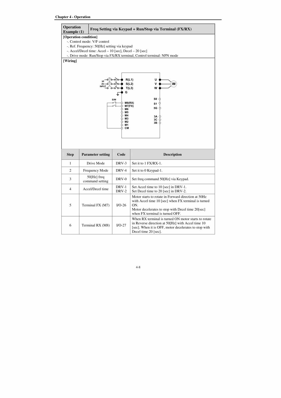
Chapter 4 - Operation
4-8
Operation Example (1)
Freq Setting via Keypad + Run/Stop via Terminal (FX/RX)
[Operation condition]
-. Control mode: V/F control
-. Ref. Frequency: 50[Hz] setting via keypad
-. Accel/Decel time: Accel – 10 [sec], Decel – 20 [sec]
-. Drive mode: Run/Stop via FX/RX terminal, Control terminal: NPN mode
[Wiring]
R(L1)
S(L2)
T(L3)
G
U
V
W
M8(RX)M7(FX)M6M5M4M3M2M1CM
S1
5G
3A3C3B
IM3PAC
INPUT
S/W S0
Step Parameter setting Code Description
1 Drive Mode DRV-3 Set it to 1 FX/RX-1.
2 Frequency Mode DRV-4 Set it to 0 Keypad-1.
3 50[Hz] freq
command setting DRV-0 Set freq command 50[Hz] via Keypad.
4 Accel/Decel time DRV-1
DRV-2
Set Accel time to 10 [sec] in DRV-1.
Set Decel time to 20 [sec] in DRV-2.
5 Terminal FX (M7) I/O-26
Motor starts to rotate in Forward direction at 50Hz
with Accel time 10 [sec] when FX terminal is turned
ON.
Motor decelerates to stop with Decel time 20[sec]
when FX terminal is turned OFF.
6 Terminal RX (M8) I/O-27
When RX terminal is turned ON motor starts to rotate
in Reverse direction at 50[Hz] with Accel time 10
[sec]. When it is OFF, motor decelerates to stop with
Decel time 20 [sec].
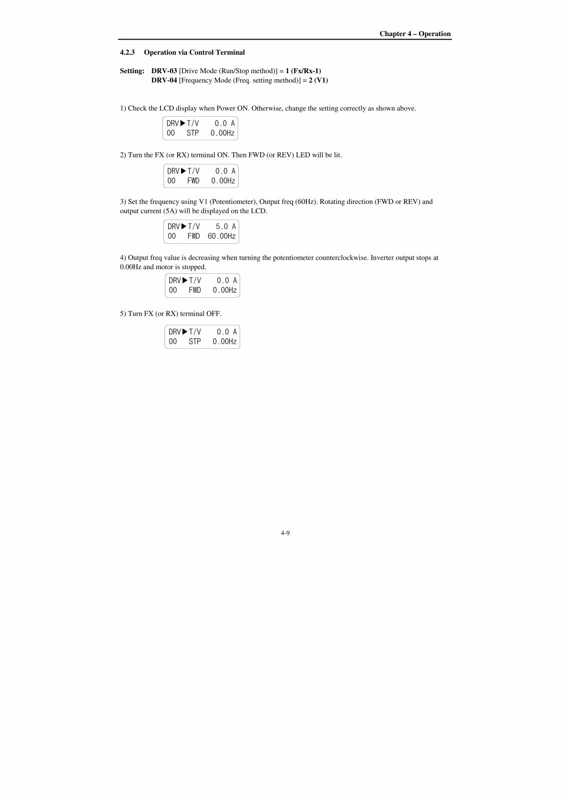
Chapter 4 – Operation
4-9
4.2.3 Operation via Control Terminal
Setting: DRV-03 [Drive Mode (Run/Stop method)] = 1 (Fx/Rx-1)
DRV-04 [Frequency Mode (Freq. setting method)] = 2 (V1)
1) Check the LCD display when Power ON. Otherwise, change the setting correctly as shown above.
2) Turn the FX (or RX) terminal ON. Then FWD (or REV) LED will be lit.
3) Set the frequency using V1 (Potentiometer), Output freq (60Hz). Rotating direction (FWD or REV) and
output current (5A) will be displayed on the LCD.
4) Output freq value is decreasing when turning the potentiometer counterclockwise. Inverter output stops at
0.00Hz and motor is stopped.
5) Turn FX (or RX) terminal OFF.
DRVT/V 0.0 A
00 STP 0.00Hz
DRVT/V 5.0 A
00 FWD 60.00Hz
DRVT/V 0.0 A
00 STP 0.00Hz
DRVT/V 0.0 A
00 FWD 0.00Hz
DRVT/V 0.0 A
00 FWD 0.00Hz
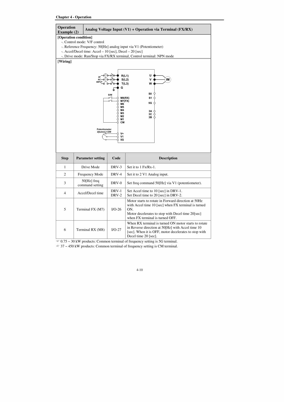
Chapter 4 - Operation
4-10
Operation Example (2)
Analog Voltage Input (V1) + Operation via Terminal (FX/RX)
[Operation condition]
-. Control mode: V/F control
-. Reference Frequency: 50[Hz] analog input via V1 (Potentiometer)
-. Accel/Decel time: Accel – 10 [sec], Decel – 20 [sec]
-. Drive mode: Run/Stop via FX/RX terminal, Control terminal: NPN mode
[Wiring]
R(L1)
S(L2)
T(L3)
G
U
V
W
M8(RX)M7(FX)M6M5M4M3M2M1CM
V+V15G
S1
5G
3A3C3B
IM3P
AC
INPUT
Potentiometer
2[kohm],1/2W
S/W S0
Step Parameter setting Code Description
1 Drive Mode DRV-3 Set it to 1 Fx/Rx-1.
2 Frequency Mode DRV-4 Set it to 2 V1 Analog input.
3 50[Hz] freq
command setting DRV-0 Set freq command 50[Hz] via V1 (potentiometer).
4 Accel/Decel time DRV-1
DRV-2
Set Accel time to 10 [sec] in DRV-1.
Set Decel time to 20 [sec] in DRV-2.
5 Terminal FX (M7) I/O-26
Motor starts to rotate in Forward direction at 50Hz
with Accel time 10 [sec] when FX terminal is turned
ON.
Motor decelerates to stop with Decel time 20[sec]
when FX terminal is turned OFF.
6 Terminal RX (M8) I/O-27
When RX terminal is turned ON motor starts to rotate
in Reverse direction at 50[Hz] with Accel time 10
[sec]. When it is OFF, motor decelerates to stop with
Decel time 20 [sec]. 0.75 ~ 30 kW products: Common terminal of frequency setting is 5G terminal. 37 ~ 450 kW products: Common terminal of frequency setting is CM terminal.
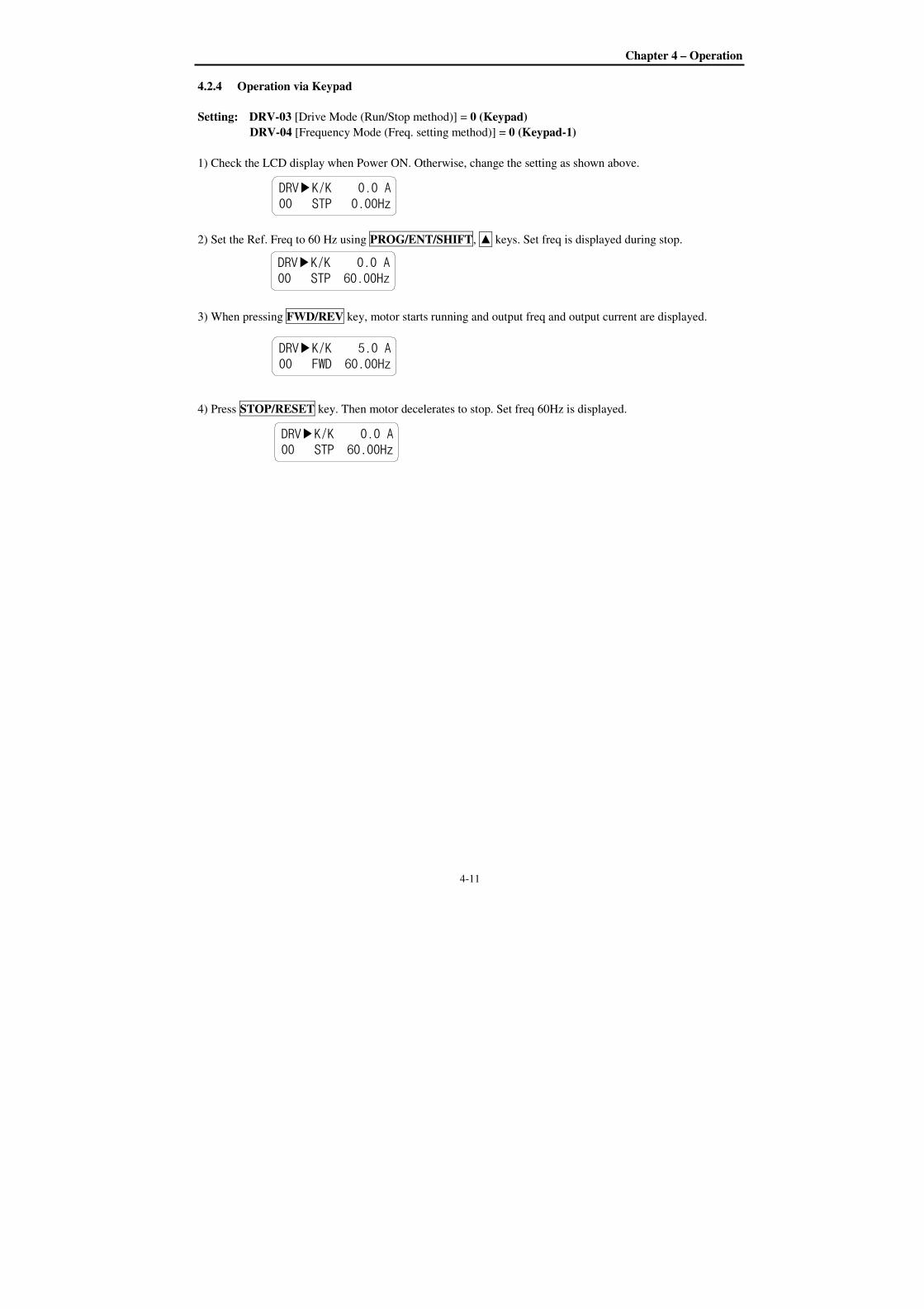
Chapter 4 – Operation
4-11
4.2.4 Operation via Keypad
Setting: DRV-03 [Drive Mode (Run/Stop method)] = 0 (Keypad)
DRV-04 [Frequency Mode (Freq. setting method)] = 0 (Keypad-1)
1) Check the LCD display when Power ON. Otherwise, change the setting as shown above.
2) Set the Ref. Freq to 60 Hz using PROG/ENT/SHIFT, keys. Set freq is displayed during stop.
3) When pressing FWD/REV key, motor starts running and output freq and output current are displayed.
4) Press STOP/RESET key. Then motor decelerates to stop. Set freq 60Hz is displayed.
DRVK/K 0.0 A
00 STP 0.00Hz
DRVK/K 0.0 A
00 STP 60.00Hz
DRVK/K 5.0 A
00 FWD 60.00Hz
DRVK/K 0.0 A
00 STP 60.00Hz

Chapter 4 - Operation
4-12
4.3 Various function setting & Description
4.3.1 Basic function parameter setting
It is the basic function setting. All settings are factory defaults unless users make change. It is recommended to
use factory setting value unless the parameter change is necessary.
1) Common parameter setting
The following table shows common parameter setting that should be checked before use regardless of control
mode.
Parameter Name Code Description
Line Freq. FU1-29 Sets a freq of the inverter input power source.
Base Frequency FU1-31 Sets the Motor Base Frequency1)
.
Motor Rated Voltage FU1-50 Sets the Motor Rated Voltage1)
.
Motor Selection FU2-40 Selects motor and voltage rating suitable to the desired
inverter.
Motor parameters FU2-41 ~ 46
Basic parameter value setting when selecting the motor
rating.
Note: If there is any discrepancy between parameter preset
value and the actual motor parameter value, change the
parameter value according to the actual motor.
Drive Mode DRV-3 Operation via Keypad, Fx/Rx-1, Fx/Rx-2 and Int 485
setting.
Frequency Mode DRV-4 Frequency reference source setting parameter
Accel/Decel time
setting
DRV-1,
DRV-2 Accel/Decel time setting
1) If FU1-31 and FU1-50 are set higher than motor nameplate value, it may cause motor overheat and if it is
set smaller than that, it may cause Over voltage trip during deceleration. Make sure to enter the actual motor
value.
2) V/F control
FU2-60 [Control mode] is set to 0 “V/F” as factory setting. Operation via V/F control is activated after the
above common parameter setting is done and the followings are set.
Parameter Name Code Description
Starting freq. FU1-32 Set frequency to start the motor.
Torque boost FU2-67 Manual or Auto torque boost settable in this parameter
Torque boost value FU2-68, FU2-69 If FU1-67 [torque boost] is set to “manual”, user sets the
desired value and the direction in code FU1-68 and 69.
3) Slip compensation
Operation is done via Slip compensation if FU2-60 is set to 1 Slip compen. This control keeps motor speed
constant regardless of load change.
Chapter 4 – Operation
4-13
4) Sensorless vector control
Set FU2-60 to “Sensorless” to enable Sensorless vector control. It is strongly recommended to perform Auto-
tuning before starting Sensorless control in order to maximize performance.
Parameter Name Code Description
Control method
selection FU2-60 Select Sensorless.
P, I gain for
sensorless control
FU2-65,
FU2-66 Set gain for Sensorless.
Starting freq FU1-32 Starting freq of the motor
Note) No-load current for Sensorless control is not entered by auto-tuning. Therefore enter the no-load
current value in V/F operation. When other than LS standard motor is used, set this value according to the motor
in use for better performance.
5) Auto-tuning of motor constant
This parameter enables auto-tuning of the motor constants. If FU2-61 is set to Yes and press the enter key, Rs,
Lsigma values begin tuning with the motor stopped. Refer to motor nameplate for the rest of other parameters.
Parameter Name Code Description
Auto-tuning FU2-61 No, Yes
Note) Motor no-load current and slip freq should be set correctly for safe and better performance. Be sure to
check these values and set them properly. Refer to Chapter 5, FU2-40~66 for more.
4.3.2 Advanced function setting
SV-iP5A inverter features advanced function parameters to maximize efficiency and performance of the motor.
It is recommended to use the factory setting unless parameter value change is inevitable.
1) V/F control
Parameter Name Code Description
V/F Pattern FU1-40
Use it according to load characteristics. If User V/F is selected,
user can select the optimum output V/F characteristic for the
application and load characteristics in [FU1-41]~[FU1-48].
Dwell operation FU2-07
FU2-08
Used to output torque in an intended direction. Inverter stops
acceleration for the preset [FU2-08] Dwell time while running
at Dwell frequency [FU2-07] and starts acceleration at
commanded frequency. Setting [FU2-08] Dwell time to 0
disable the Dwell operation.
Jump Frequency FU2-10
FU2-11~16
When it is desired to avoid resonance attributable to the natural
frequency of a mechanical system, these parameters allow
resonant frequencies to be jumped. Up to three areas can be set,
with the jump frequencies set to either the top or bottom point
of each area. To enable the function, set [FU2-10] to ‘Yes’ and
set the value in [FU2-11]~[FU2-16].
Accel/Decel pattern
S-curve
FU1-2, 3
FU1-4, 5
This pattern has an effect on the prevention of cargo collapse
on conveyor etc and reduction in an acceleration/ deceleration
shock.

Chapter 4 - Operation
4-14
2) Sensorless vector control
Related parameters for starting in Sensorless vector control when FU2-60 [Control Mode Selection] is set to
Sensorless.
Parameter Name Code Description
When starting FU2-64 Pre-excitation time setting
I/O-20~27 Programmable Digital Input terminals define
3) Parameters to monitor motor and inverter status
Parameter Name Code Description
Output current/
motor speed DRV-8~9 Displays output current and motor rpm.
DC link voltage DRV-10 Displays DC link voltage.
User display selection
(Voltage and watt)
DRV-11
FU2-81
Either output voltage or power selected in FU2-81 is
displayed in DRV-11.
Fault display DRV-12 Displays the current inverter fault.
TAR / OUT
Freq. display DRV-14
Displays Target freq. for Accel/Decel & Output freq
during Accel/Decel.
REF/FBK display DRV-15 Displays PID Reference/ Feedback frequency display.
Speed (Hz / Rpm)
selection DRV-16 Selects inverter output speed unit [Hz or Rpm]
PID parameter DRV-18 Displays related parameters of PID controller.
AD parameter DRV-19 Displays inverter analog input value to AD value.
EXT - PID parameter DRV-20 Displays related parameters of EXT–PID controller.
Note) DRV-15, DRV-18 only displayed when APP-02 [proc PI mode] is set to “Yes.” DRV-20 only
displayed when APP-80 [Ext PI mode] is set to “Yes.”
5) Parameter initialize
Parameter Name Code Description
Software version FU2-82 Displays the inverter software version.
Parameter
Read/Write/Initialize/
Lock
FU2-91
FU2-92
FU2-93
FU2-94
FU2-95
[FU2-91], [FU2-92]: Copying parameters from other
inverter
[FU2-93]: Initializing parameters to factory setting values
[FU2-94]: Parameter write disabled
[FU2-95]: Parameter save
Note: Motor parameters (FU2-40~46, FU2-62~63) returned to factory setting once Parameter Read/Write is
executed.
Chapter 4 – Operation
4-15
6) Protection & Trip level setting
Parameter Name Code Description
Electronic thermal
FU1-60
FU1-61
FU1-62
FU1-63
Protection of the motor from overheating without the use
of external thermal relay. Refer to parameter descriptions
for more detail.
Overload alarm & trip
FU1-64
FU1-65
FU1-66
FU1-67
FU1-68
Warning alarm outputs and displays the trip message
when overcurrent above the threshold value keeps on.
Stall prevention FU1-70
FU1-71
Set the output current level at which the output freq will
be adjusted to prevent the motor from stopping due to
over-current etc. It activates during accel/ constant
speed/decel to prevent the motor stall.
7) Starting / Accel/ Decel / Stopping pattern setting
Parameter Name Code Description
Accel/Decel pattern FU1-02
FU1-03
2 types of Accel/Decel pattern: ‘S-curve’, ’U-curve’
settable according to application and load characteristic. If
‘S-curve’ is selected, the desired value of [FU1-4], [FU1-
5] is settable.
Starting/Stopping
method
FU1-20
FU1-23
4 types of stopping method ‘Decel’, ‘DC-brake’, ‘Free-
run’, ‘Flux Brake’ selectable. If ‘DC-brake’ is selected,
the desired value of [FU1-21, 22], [FU1-24]~ [FU1-27] is
settable. See function description of chapter 5 for more
details.
Frequency Limit
selection
FU1-33
FU1-34
FU1-35
Limits the active frequency. Inverter operates at the freq
range between upper freq limit [FU1-35] and bottom freq
limit [FU1-34] and higher/ lower freq value is entered, it
is automatically replaced by limit value. Setting range:
[FU1-30] Maximum freq to [FU1-32] starting freq.
8) Operation-starting method
Parameter Name Code Description
Starting method
FU2-20
FU2-21
FU2-25
FU2-26
Motor starting method:
[FU2-20]: Power-on run,
[FU2-21] Restart after Fault Reset,
[FU2-25] Number of Auto Restart Attempt
[FU2-26] Delay Time Before Auto Restart
See parameter description for more details.
Speed Search
Selection
FU2-22
FU2-23
FU2-24
Speed search function is available during Accel, trip,
instant power failure, restart after fault reset and Speed
search at auto restart. See parameter description for more
details.
Chapter 4 - Operation
4-16
4.3.3 Application function setting
1) PID operation
Inverter can be used to exercise process control, e.g. flow rate, air volume or pressure via PID feedback
control.
Parameter Name Code Description
PID control setting APP-02 ~ APP-17 Parameters for PID control setting See Chapter 6. PID feedback operation.
2) Ext PID operation
It is used for External PID feedback control.
Parameter Name Code Description
ExtPID setting APP-80 ~ APP-97 Parameters for Ext PID See Chapter 6. External PID operation.
3) Pre PID operation
It helps to begin smooth start of the PID control.
Parameter Name Code Description
PrePID setting APP-74 ~ APP-76 Parameters for Pre PID operation See Chapter 6. Pre PID operation.
4) MMC operation
Inverter controls a whole system by controlling Main motor connected directly to the inverter and Aux motors
connected to the inverter relays and operated via relay On/Off.
Parameter Name Code Description
MMC setting APP-40 ~ APP-71
I/O-20 ~ I/O-27 Parameters for MMC operation See Chapter 6. MMC operation.
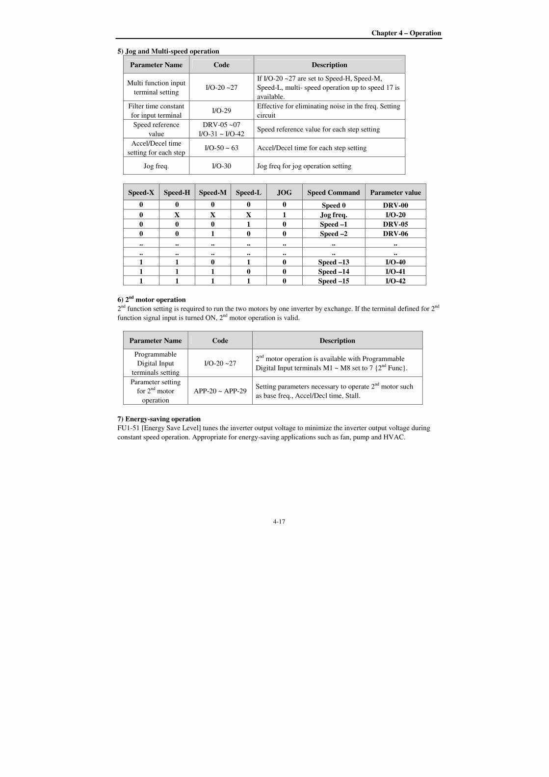
Chapter 4 – Operation
4-17
5) Jog and Multi-speed operation
Parameter Name Code Description
Multi function input
terminal setting I/O-20 ~27
If I/O-20 ~27 are set to Speed-H, Speed-M,
Speed-L, multi- speed operation up to speed 17 is
available.
Filter time constant
for input terminal I/O-29
Effective for eliminating noise in the freq. Setting
circuit
Speed reference
value
DRV-05 ~07
I/O-31 ~ I/O-42 Speed reference value for each step setting
Accel/Decel time
setting for each step I/O-50 ~ 63 Accel/Decel time for each step setting
Jog freq. I/O-30 Jog freq for jog operation setting
Speed-X Speed-H Speed-M Speed-L JOG Speed Command Parameter value
0 0 0 0 0 Speed 0 DRV-00
0 X X X 1 Jog freq. I/O-20
0 0 0 1 0 Speed –1 DRV-05
0 0 1 0 0 Speed –2 DRV-06
.. .. .. .. .. .. ..
.. .. .. .. .. .. ..
1 1 0 1 0 Speed –13 I/O-40
1 1 1 0 0 Speed –14 I/O-41
1 1 1 1 0 Speed –15 I/O-42
6) 2nd motor operation
2nd
function setting is required to run the two motors by one inverter by exchange. If the terminal defined for 2nd
function signal input is turned ON, 2nd
motor operation is valid.
Parameter Name Code Description
Programmable
Digital Input
terminals setting
I/O-20 ~27 2
nd motor operation is available with Programmable
Digital Input terminals M1 ~ M8 set to 7 2nd
Func.
Parameter setting
for 2nd
motor
operation
APP-20 ~ APP-29 Setting parameters necessary to operate 2
nd motor such
as base freq., Accel/Decl time, Stall.
7) Energy-saving operation
FU1-51 [Energy Save Level] tunes the inverter output voltage to minimize the inverter output voltage during
constant speed operation. Appropriate for energy-saving applications such as fan, pump and HVAC.
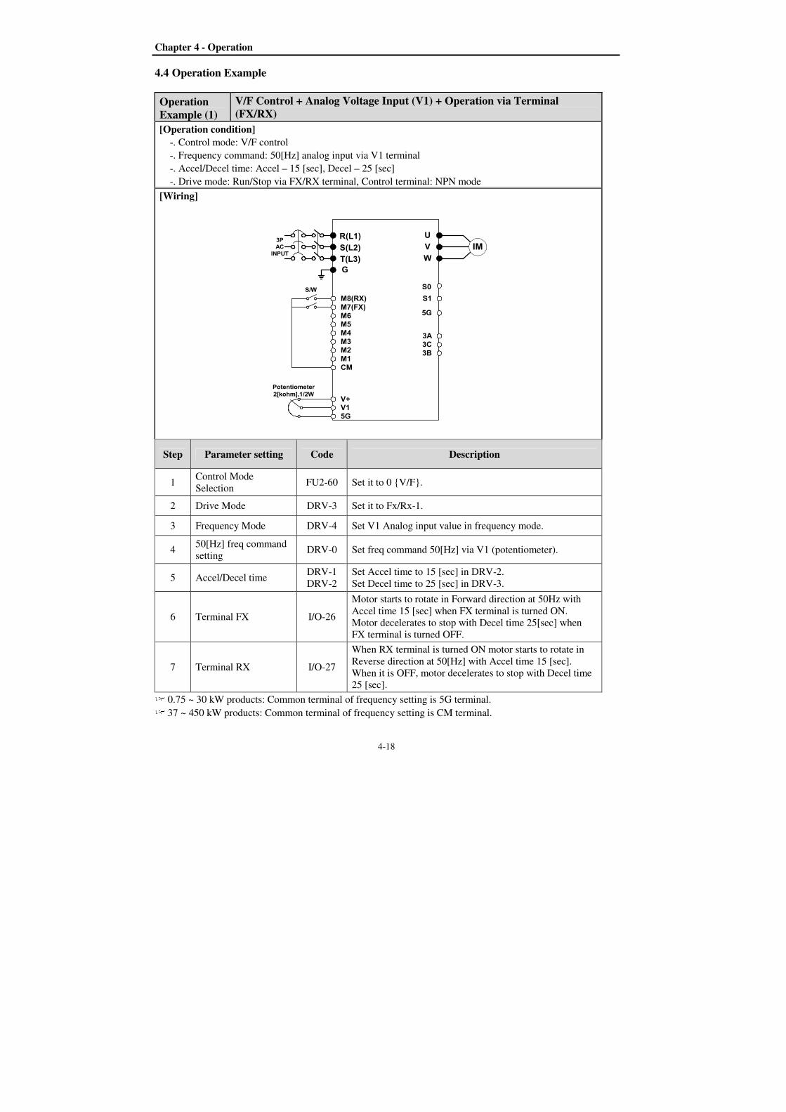
Chapter 4 - Operation
4-18
4.4 Operation Example
Operation Example (1)
V/F Control + Analog Voltage Input (V1) + Operation via Terminal (FX/RX)
[Operation condition]
-. Control mode: V/F control
-. Frequency command: 50[Hz] analog input via V1 terminal
-. Accel/Decel time: Accel – 15 [sec], Decel – 25 [sec]
-. Drive mode: Run/Stop via FX/RX terminal, Control terminal: NPN mode
[Wiring]
R(L1)
S(L2)
T(L3)
G
U
V
W
M8(RX)M7(FX)M6M5M4M3M2M1CM
V+V15G
S1
5G
3A3C3B
IM3P
AC
INPUT
Potentiometer2[kohm],1/2W
S/W S0
Step Parameter setting Code Description
1 Control Mode
Selection FU2-60 Set it to 0 V/F.
2 Drive Mode DRV-3 Set it to Fx/Rx-1.
3 Frequency Mode DRV-4 Set V1 Analog input value in frequency mode.
4 50[Hz] freq command
setting DRV-0 Set freq command 50[Hz] via V1 (potentiometer).
5 Accel/Decel time DRV-1
DRV-2
Set Accel time to 15 [sec] in DRV-2.
Set Decel time to 25 [sec] in DRV-3.
6 Terminal FX I/O-26
Motor starts to rotate in Forward direction at 50Hz with
Accel time 15 [sec] when FX terminal is turned ON.
Motor decelerates to stop with Decel time 25[sec] when
FX terminal is turned OFF.
7 Terminal RX I/O-27
When RX terminal is turned ON motor starts to rotate in
Reverse direction at 50[Hz] with Accel time 15 [sec].
When it is OFF, motor decelerates to stop with Decel time
25 [sec]. 0.75 ~ 30 kW products: Common terminal of frequency setting is 5G terminal. 37 ~ 450 kW products: Common terminal of frequency setting is CM terminal.
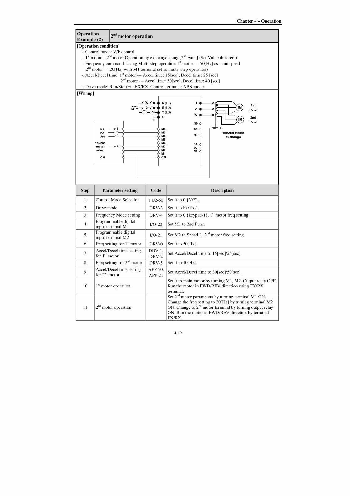
Chapter 4 – Operation
4-19
Operation Example (2)
2nd motor operation
[Operation condition]
-. Control mode: V/F control
-. 1st motor + 2
nd motor Operation by exchange using [2
nd Func] (Set Value different)
-. Frequency command: Using Multi-step operation 1st motor --- 50[Hz] as main speed
2nd
motor --- 20[Hz] with M1 terminal set as multi- step operation)
-. Accel/Decel time: 1st motor --- Accel time: 15[sec], Decel time: 25 [sec]
2nd
motor --- Accel time: 30[sec], Decel time: 40 [sec]
-. Drive mode: Run/Stop via FX/RX, Control terminal: NPN mode
[Wiring]
R
S
T
G
U
V
W
M8M7M6M5M4M3M2M1CM
S1
5G
3A3C3B
IM1st
motor3P AC
INPUT
IM2ndmotor
1st/2nd motor
exchange
RXFX
Jog
CM
1st/2ndmotor
select
S0
Step Parameter setting Code Description
1 Control Mode Selection FU2-60 Set it to 0 V/F.
2 Drive mode DRV-3 Set it to Fx/Rx-1.
3 Frequency Mode setting DRV-4 Set it to 0 keypad-1. 1st motor freq setting
4 Programmable digital
input terminal M1 I/O-20 Set M1 to 2nd Func.
5 Programmable digital
input terminal M2 I/O-21 Set M2 to Speed-L. 2
nd motor freq setting
6 Freq setting for 1st motor DRV-0 Set it to 50[Hz].
7 Accel/Decel time setting
for 1st motor
DRV-1,
DRV-2 Set Accel/Decel time to 15[sec]/25[sec].
8 Freq setting for 2nd
motor DRV-5 Set it to 10[Hz].
9 Accel/Decel time setting
for 2nd
motor
APP-20,
APP-21 Set Accel/Decel time to 30[sec]/50[sec].
10 1st motor operation
Set it as main motor by turning M1, M2, Output relay OFF.
Run the motor in FWD/REV direction using FX/RX
terminal.
11 2nd
motor operation
Set 2nd
motor parameters by turning terminal M1 ON.
Change the freq setting to 20[Hz] by turning terminal M2
ON. Change to 2nd
motor terminal by turning output relay
ON. Run the motor in FWD/REV direction by terminal
FX/RX.
(L1)
(L2)
(L3)
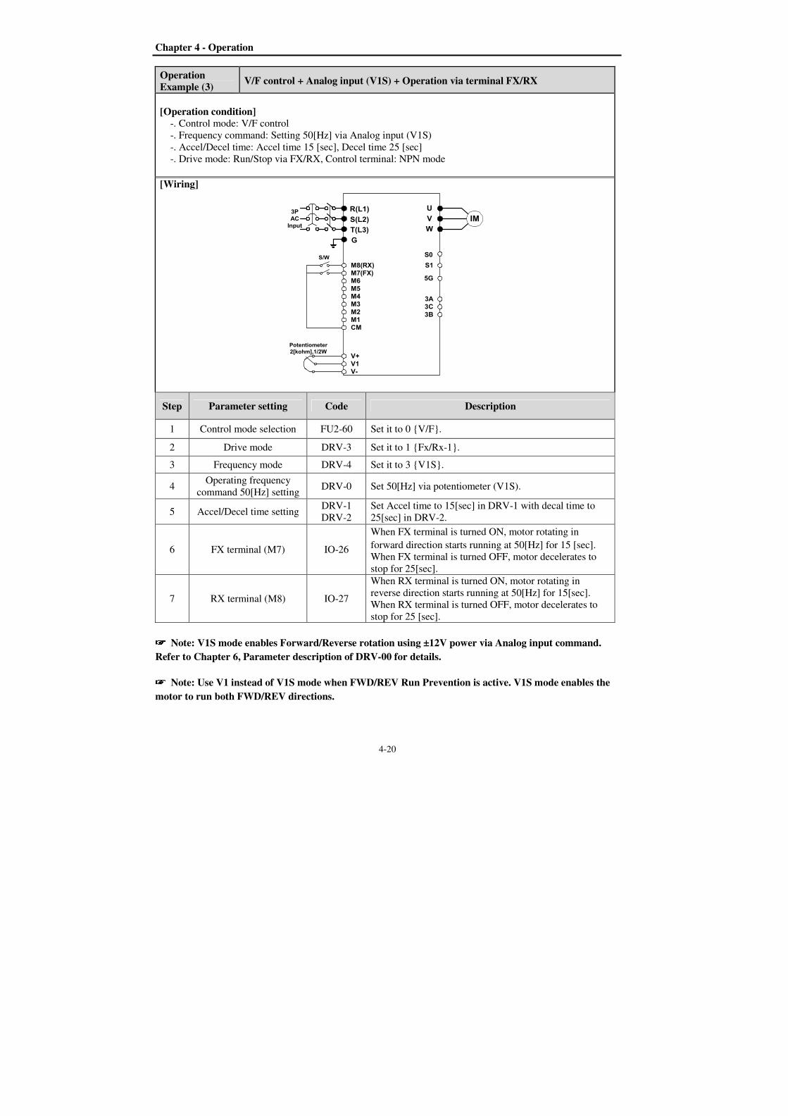
Chapter 4 - Operation
4-20
Operation Example (3)
V/F control + Analog input (V1S) + Operation via terminal FX/RX
[Operation condition]
-. Control mode: V/F control
-. Frequency command: Setting 50[Hz] via Analog input (V1S)
-. Accel/Decel time: Accel time 15 [sec], Decel time 25 [sec]
-. Drive mode: Run/Stop via FX/RX, Control terminal: NPN mode
[Wiring]
R(L1)
S(L2)
T(L3)
G
U
V
W
M8(RX)M7(FX)M6M5M4M3M2M1CM
V+V1V-
S1
5G
3A3C3B
IM3PACInput
Potentiometer
2[kohm],1/2W
S/W S0
Step Parameter setting Code Description
1 Control mode selection FU2-60 Set it to 0 V/F.
2 Drive mode DRV-3 Set it to 1 Fx/Rx-1.
3 Frequency mode DRV-4 Set it to 3 V1S.
4 Operating frequency
command 50[Hz] setting DRV-0 Set 50[Hz] via potentiometer (V1S).
5 Accel/Decel time setting DRV-1
DRV-2
Set Accel time to 15[sec] in DRV-1 with decal time to
25[sec] in DRV-2.
6 FX terminal (M7) IO-26
When FX terminal is turned ON, motor rotating in
forward direction starts running at 50[Hz] for 15 [sec].
When FX terminal is turned OFF, motor decelerates to
stop for 25[sec].
7 RX terminal (M8) IO-27
When RX terminal is turned ON, motor rotating in
reverse direction starts running at 50[Hz] for 15[sec].
When RX terminal is turned OFF, motor decelerates to
stop for 25 [sec].
Note: V1S mode enables Forward/Reverse rotation using ±12V power via Analog input command.
Refer to Chapter 6, Parameter description of DRV-00 for details.
Note: Use V1 instead of V1S mode when FWD/REV Run Prevention is active. V1S mode enables the
motor to run both FWD/REV directions.

Chapter 4 – Operation
4-21
Note: If the inverter is operated without wiring a motor, trip occurs as below because the protection
function is active automatically. In this case, refer to the related parameters(FU1 57 ~ 59). Trip is reset if
the inverter is powered down and up once again.
In case that a simple trial run is needed such as a check on basic operation state without a wiring a motor,
FU1-57(No Motor Sel) should be set to [No].
DRVDRVDRVDRV Fault Fault Fault Fault
12121212 HWHWHWHW---- DiagDiagDiagDiag
DRVDRVDRVDRV Fault Fault Fault Fault
12121212 No Motor Trip No Motor Trip No Motor Trip No Motor Trip
FU1 FU1 FU1 FU1 No Motor SelNo Motor SelNo Motor SelNo Motor Sel
57575757 Yes Yes Yes Yes
FU1 FU1 FU1 FU1 No Motor Sel No Motor Sel No Motor Sel No Motor Sel
57575757 No No No No


5-1
CHAPTER 5 - PARAMETER LIST
5.1 Parameter groups The parameters of SV-IP5A Series are divided into 5 functions groups in accordance with the application.
Their names, principal contents and LCD keypad displays are shown below.
Name of Group LCD Keypad Display Description
Drive Group
[DRV]
Target frequency and Accel/ Decel Time, etc.
Basic parameters
Function1 Group
[FU1]
Maximum Frequency and Protection, etc
Parameters regarding basic functions
Function2 Group
[FU2]
Frequency Jump and Frequency Limit, etc
Parameters regarding application functions
Input/Output Group
[I/O]
Programmable Digital terminal Define and
Analog Command, etc
Parameters necessary for sequence configuration
Application Group
[APP]
PID, MMC, and 2
nd motor, etc
Parameters regarding application functions
APP APP APP APP Jump codeJump codeJump codeJump code
00000000 1111
DRVDRVDRVDRV T/K T/K T/K T/K 0.0 A0.0 A0.0 A0.0 A
00000000 STP STP STP STP 0 .00Hz0 .00Hz0 .00Hz0 .00Hz
FU1 FU1 FU1 FU1 Jump codeJump codeJump codeJump code
00000000 1111
FU2 FU2 FU2 FU2 Jump codeJump codeJump codeJump code
00000000 40404040
I/O I/O I/O I/O Jump codeJump codeJump codeJump code
00000000 1111
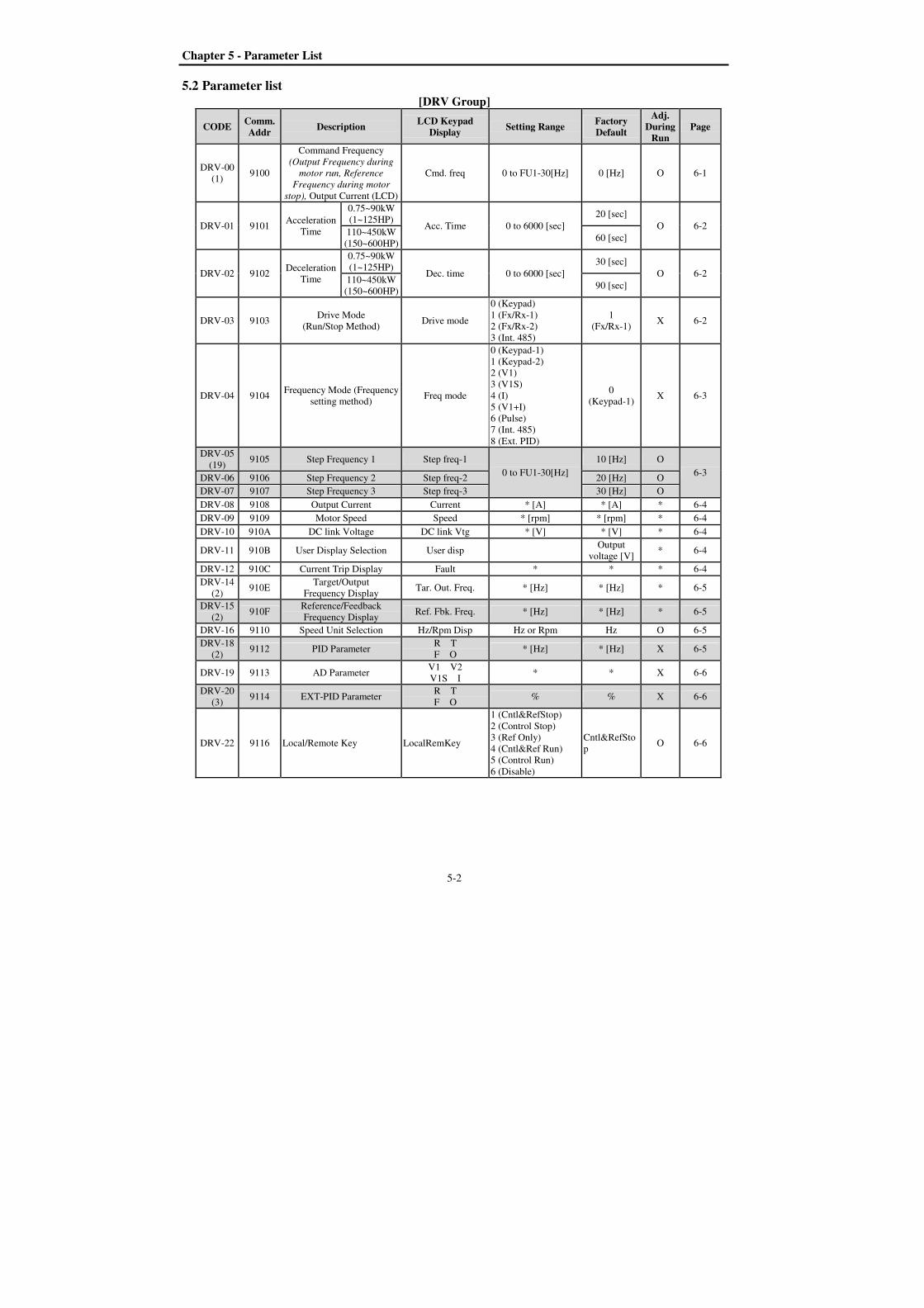
Chapter 5 - Parameter List
5-2
5.2 Parameter list
[DRV Group]
CODE Comm. Addr
Description LCD Keypad
Display Setting Range
Factory Default
Adj. During
Run Page
DRV-00
(1) 9100
Command Frequency
(Output Frequency during
motor run, Reference
Frequency during motor
stop), Output Current (LCD)
Cmd. freq 0 to FU1-30[Hz] 0 [Hz] O 6-1
DRV-01 9101 Acceleration
Time
0.75~90kW
(1~125HP) Acc. Time 0 to 6000 [sec]
20 [sec]
O 6-2 110~450kW
(150~600HP) 60 [sec]
DRV-02 9102 Deceleration
Time
0.75~90kW
(1~125HP) Dec. time 0 to 6000 [sec]
30 [sec]
O 6-2 110~450kW
(150~600HP) 90 [sec]
DRV-03 9103 Drive Mode
(Run/Stop Method) Drive mode
0 (Keypad)
1 (Fx/Rx-1)
2 (Fx/Rx-2)
3 (Int. 485)
1
(Fx/Rx-1) X 6-2
DRV-04 9104 Frequency Mode (Frequency
setting method) Freq mode
0 (Keypad-1)
1 (Keypad-2)
2 (V1)
3 (V1S)
4 (I)
5 (V1+I)
6 (Pulse)
7 (Int. 485)
8 (Ext. PID)
0
(Keypad-1) X 6-3
DRV-05
(19) 9105 Step Frequency 1 Step freq-1
0 to FU1-30[Hz]
10 [Hz] O
6-3 DRV-06 9106 Step Frequency 2 Step freq-2 20 [Hz] O
DRV-07 9107 Step Frequency 3 Step freq-3 30 [Hz] O
DRV-08 9108 Output Current Current * [A] * [A] * 6-4
DRV-09 9109 Motor Speed Speed * [rpm] * [rpm] * 6-4
DRV-10 910A DC link Voltage DC link Vtg * [V] * [V] * 6-4
DRV-11 910B User Display Selection User disp Output
voltage [V] * 6-4
DRV-12 910C Current Trip Display Fault * * * 6-4
DRV-14
(2) 910E
Target/Output
Frequency Display Tar. Out. Freq. * [Hz] * [Hz] * 6-5
DRV-15
(2) 910F
Reference/Feedback
Frequency Display Ref. Fbk. Freq. * [Hz] * [Hz] * 6-5
DRV-16 9110 Speed Unit Selection Hz/Rpm Disp Hz or Rpm Hz O 6-5
DRV-18
(2) 9112 PID Parameter
R T
F O * [Hz] * [Hz] X 6-5
DRV-19 9113 AD Parameter V1 V2
V1S I * * X 6-6
DRV-20
(3) 9114 EXT-PID Parameter
R T
F O % % X 6-6
DRV-22 9116 Local/Remote Key LocalRemKey
1 (Cntl&RefStop)
2 (Control Stop)
3 (Ref Only)
4 (Cntl&Ref Run)
5 (Control Run)
6 (Disable)
Cntl&RefSto
p O 6-6

Chapter 5 – Parameter List
5-3
CODE Comm. Addr
Description LCD Keypad
Display Setting Range
Factory Default
Adj. During
Run Page
RV-23 9117 Keypad Mode Key Ref Mode
1 (Minimum Spd)
2 (Last Spd)
3 (Preset Spd 1)
4 (Stop)
5 (Fault)
6 (Disable)
Disable O 6-7
DRV-91
(4) 915B Drive mode 2 Drive mode2
0 (Keypad)
1 (Fx/Rx-1)
2 (Fx//Rx-2)
1
(Fx/Rx-1) X
DRV-92 915C Frequency mode 2 Freq mode2
0 (Keypad-1)
1 (Keypad-2)
2 (V1)
3 (V1S)
4 (I)
5 (V1+I)
6 (Pulse)
0
(Keypad-1) X
* The gray-highlighted codes are hidden parameters and will appear when the related functions are to be set.
(1) The speed unit is changed from [Hz] to [%] when DRV-16 is set to [Rpm]. Only User Unit will be displayed when
APP-02 is set to [Yes] and when APP-06 is set to either I, V1 or Pulse and when one of I/O-86~ I/O-88 is set to
either [Speed] (Hz or Rpm), [Percent], [Bar], [mBar], [kPa] or [Pa].
Output Frequency (Hz or Rpm; Unit of outupt speed) is displayed in DRV-00 during the Inverter is running.
User Unit reference (Unit of PID controller selected) is displayed in DRV-00 during the Inverter is not
running.
(2) DRV-15, DRV-18 will appear when APP-02 [Process PI Mode] is set to “Yes”. Also User Unit is displayed when
one of I/O-86~ I/O-88 is set to either [Speed](Hz or Rpm), [Percent], [Bar], [mBar], [kPa] or [Pa].
(3)DRV-20 will appear when APP-80 [ExtProcess PI Mode] is set to “Yes”.
(4) DRV-91/92 will appear only when DRV-22 is set to [2nd Source].
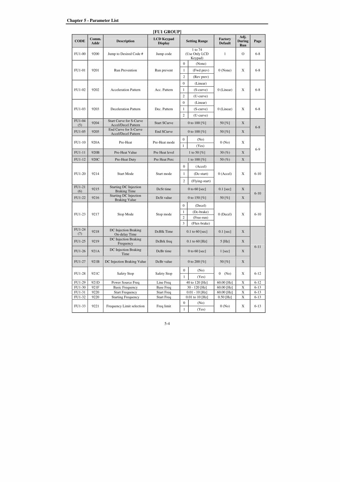
Chapter 5 - Parameter List
5-4
[FU1 GROUP]
CODE Comm. Addr
Description LCD Keypad
Display Setting Range
Factory Default
Adj. During
Run Page
FU1-00 9200 Jump to Desired Code # Jump code
1 to 74
(Use Only LCD
Keypad)
1 O 6-8
FU1-01 9201 Run Prevention Run prevent
0 (None)
0 (None) X 6-8 1 (Fwd prev)
2 (Rev prev)
FU1-02 9202 Acceleration Pattern Acc. Pattern
0 (Linear)
0 (Linear) X 6-8 1 (S-curve)
2 (U-curve)
FU1-03 9203 Deceleration Pattern Dec. Pattern
0 (Linear)
0 (Linear) X 6-8 1 (S-curve)
2 (U-curve)
FU1-04
(5) 9204
Start Curve for S-Curve
Accel/Decel Pattern Start SCurve 0 to 100 [%] 50 [%] X
6-8
FU1-05 9205 End Curve for S-Curve
Accel/Decel Pattern End SCurve 0 to 100 [%] 50 [%] X
FU1-10 920A Pre-Heat Pre-Heat mode 0 (No)
0 (No) X
6-9 1 (Yes)
FU1-11 920B Pre-Heat Value Pre Heat level 1 to 50 [%] 30 (%) X
FU1-12 920C Pre-Heat Duty Pre Heat Perc 1 to 100 [%] 50 (%) X
FU1-20 9214 Start Mode Start mode
0 (Accel)
0 (Accel) X 6-10 1 (Dc-start)
2 (Flying-start)
FU1-21
(6) 9215
Starting DC Injection
Braking Time DcSt time 0 to 60 [sec] 0.1 [sec] X
6-10
FU1-22 9216 Starting DC Injection
Braking Value DcSt value 0 to 150 [%] 50 [%] X
FU1-23 9217 Stop Mode Stop mode
0 (Decel)
0 (Decel) X 6-10 1 (Dc-brake)
2 (Free-run)
3 (Flux-brake)
FU1-24
(7) 9218 DC Injection Braking
On-delay Time DcBlk Time 0.1 to 60 [sec] 0.1 [sec] X
6-11
FU1-25 9219 DC Injection Braking
Frequency DcBrk freq 0.1 to 60 [Hz] 5 [Hz] X
FU1-26 921A DC Injection Braking
Time DcBr time 0 to 60 [sec] 1 [sec] X
FU1-27 921B DC Injection Braking Value DcBr value 0 to 200 [%] 50 [%] X
FU1-28 921C Safety Stop Safety Stop 0 (No)
0 (No) X 6-12 1 (Yes)
FU1-29 921D Power Source Freq Line Freq 40 to 120 [Hz] 60.00 [Hz] X 6-12
FU1-30 921F Basic Frequency Base Freq 30 - 120 [Hz] 60.00 [Hz] X 6-13
FU1-31 9220 Start Frequency Start Freq 0.01 - 10 [Hz] 60.00 [Hz] X 6-13
FU1-32 9220 Starting Frequency Start Freq 0.01 to 10 [Hz] 0.50 [Hz] X 6-13
FU1-33 9221 Frequency Limit selection Freq limit 0 (No)
0 (No) X 6-13 1 (Yes)

Chapter 5 – Parameter List
5-5
CODE Comm. Addr
Description LCD Keypad
Display Setting Range
Factory Default
Adj. During
Run Page
FU1-34
(8) 9222 Freq Lower Limit Lim Lo Freq 0 – FU1-35 0.50 [Hz] 6-13
FU1-35 9223 Freq Upper Limit Lim Hi Freq FU1-34 – FU1-30 60.00 [Hz] X 6-13
FU1-40 9228 Volts/Hz Pattern V/F Pattern
0 (Linear)
0 (Linear) X 6-14 1 (Square)
2 (User V/F)
FU1-41
(9) 9229 User V/F – Frequency 1 User freq 1 0 to FU1-30 15.00 [Hz] X
6-14
FU1-42 922A User V/F – Voltage 1 User volt 1 0 to 100 [%] 25 [%] X
FU1-43 922B User V/F – Frequency 2 User freq 2 0 to FU1-30 30.00 [Hz] X
FU1-44 922C User V/F – Voltage 2 User volt 2 0 to 100 [%] 50 [%] X
FU1-45 922D User V/F – Frequency 3 User freq 3 0 to FU1-30 45.00 [Hz] X
FU1-46 922E User V/F – Voltage 3 User volt 3 0 to 100 [%] 75 [%] X
FU1-47 922F User V/F – Frequency 4 User freq 4 0 to FU1-30 60.00 [Hz] X
FU1-48 9230 User V/F – Voltage 4 User volt 4 0 to 100 [%] 100[%] X
FU1-49 9231 Input voltage adjustment
200/400/(600V type)
VAC
220.0V/380.0V
/(575.0V)
73 to 115.0 [%]
(77.6 to 115.0 [%])
100.0 [%]/
86.4 [%]
(100.0 [%])
X 6-15
FU1-50 9232 Motor Rated Voltage
(600V type) Motor Volt 0 to 600 [V]
220/380 [V]
(575[V]) X 6-15
FU1-51 9233 Energy Save Energy save
0 (None)
0 (None) X
6-15
1 (Manual)
2 (Auto)
FU1-52
(10) 9234 Energy Save % Manual save% 0 to 30 [%] 0 [%] O
FU1-54 9236 Integrating Wattmeter KiloWattHour M kWh * X 6-16
FU1-55 9237 Inverter Temperature Inv. Temp. 0 to 160 [degree] * X 6-16
FU1-56 9238 Motor Temperature Motor Temp. 0 to 160 [degree] * X 6-16
FU1-57 9239 No Motor Selection No Motor Sel 0 (No)
0 (No) X 6-16 1 (Yes)
FU1-58 923A Trip Current Level No Motor Level 5 to 100 [%] 15 [%] X 6-16
FU1-59 923B Trip Time Setting No Motor Time 0.5 to 10.0 [sec] 3.0 [sec] X 6-16
FU1-60 923C Electronic Thermal Selection ETH select 0 (No)
1 (Yes) O 6-17 1 (Yes)
FU1-61
(11) 923D
Electronic Thermal Level for
1 Minute ETH 1min FU1-62 to 200 [%] 150 [%] O 6-17
FU1-62 923E Electronic Thermal Level for
Continuous ETH Cont
50 to FU1-61
(Maximum 150%)) 120 [%] O 6-17
FU1-63 923F Characteristic Selection
(Motor Type) Motor type
0 (Self-cool)
1 (Forced-cool) 0 (Self-cool) O 6-17
FU1-64 9240 Overload Warning Level OL level 30 to 110 [%] 110 [%] O 6-18
FU1-65 9241 Overload Warning Time OL time 0 to 30 [sec] 10 [sec] O 6-18
FU1-66 9242 Overload Trip Selection OLT select 0 (No)
0 (No) O 6-18 1 (Yes)
FU1-67
(12) 9243 Overload Trip Level OLT level 30 to 150 [%] 120[%] O 6-18
FU1-68 9244 Overload Trip Delay Time OLT time 0 to 60 [sec] 60 [sec] O 6-18
FU1-69 9245 Input/Output Phase Loss
Protection Trip select 000 to 111 (Bit Set) 100 O 6-19
FU1-70 9246 Stall Prevention Selection Stall Mode. No
Yes No X 6-19
FU1-71 9247 Stall Prevention Level Stall level 30 to 200 [%] 120[%] X 6-19
FU1-72 9248 Accel/Decel Change
Frequency Acc/Dec ch F 0 to FU1-30 0 [Hz] X 6-19

Chapter 5 - Parameter List
5-6
CODE Comm. Addr
Description LCD Keypad
Display Setting Range
Factory Default
Adj. During
Run Page
FU1-73 9249 Reference Frequency for
Accel and Decel Acc/Dec freq
0 (Max freq) 0 (Max freq) X 6-20
1 (Delta freq)
FU1-74 924A Accel/Decel Time Scale Time scale
0 (0.01 sec)
1 (0.1 sec) O 6-20 1 (0.1 sec)
2 (1 sec)
FU1-75 924B Up Down Save Mode UpDnSaveMode 0 (No)
0 (No) X 6-20 1 (Yes)
FU1-76
(31) 924C Up Down Save Freq UpDnSaveFreq startFreq to 120[Hz] 0.00Hz O 6-20
* The gray-highlighted codes are hidden parameters and will appear when the related functions are to be set.
(5) Only displayed when FU1-02, FU1-03 is set to [S-Curve].
(6) Only displayed when FU1-20 is set to [DC-start].
(7) Only displayed when FU1-23 is set to [DC-break].
(8) Only displayed when FU1-33 is set to [Yes].
(9) FU1-41~48 Only displayed when FU1-40 is set to [User V/F].
(10) Only displayed when FU1-51 is set to [Manual].
(11) Only displayed when FU1-60 is set to [Yes].
(12) Only displayed when FU1-66 is set to [Yes].
(31) Only displayed when FU1-75 is set to [Yes].

Chapter 5 – Parameter List
5-7
[FU2 GROUP]
CODE Comm. Addr
Description LCD Keypad
Display Setting Range
Factory Default
Adj. During
Run Page
FU2-00 9300 Jump to desired code # Jump code
1 to 95
(Use Only LCD
Keypad)
40 O 6-21
FU2-01 9301 Last trip 1 Last trip-1 By pressing [PROG]
and [UP] or [DOWN]
key, the frequency,
current, and
operational status at
the time of fault can
be seen.
0 (None) * 6-21
FU2-02 9302 Last trip 2 Last trip-2 0 (None) * 6-21
FU2-03 9303 Last trip 3 Last trip-3 0 (None) * 6-21
FU2-04 9304 Last trip 4 Last trip-4 0 (None) * 6-21
FU2-05 9305 Last trip 5 Last trip-5 0 (None) * 6-21
FU2-06 9306 Erase trips Erase trips 0 (No)
0 (No) O 6-21 1 (Yes)
FU2-07 9307 Dwell Frequency Dwell time 0 to 10 [sec] 0 [sec] X 6-21
FU2-08
(12) 9308 Dwell Frequency Dwell freq FU1-32 to FU1-30 5 [Hz] X 6-21
FU2-10 930A Frequency Jump Selection Jump Freq 0 (No)
0 (No) X 6-21 1 (Yes)
FU2-11
(13) 930B Jump Frequency 1 Low jump lo 1 0 to FU2-12 10 [Hz] O
6-21
FU2-12 930C Jump Frequency 1 High jump Hi 1 FU2-11 to FU1-30 15 [Hz] O
FU2-13 930D Jump Frequency 2 Low jump lo 2 0 to FU2-14 20 [Hz] O
FU2-14 930E Jump Frequency 2 High jump Hi 2 FU2-13 to FU1-30 25 [Hz] O
FU2-15 930F Jump Frequency 3 Low jump lo 3 0 to FU2-16 30 [Hz] O
FU2-16 9310 Jump Frequency 3 High jump Hi 3 FU2-15 to FU1-30 35 [Hz] O
FU2-20 9314 Power ON Start Selection Power-on run
RST restart
0 (No)
0 (No) O
6-22
1 (Yes)
FU2-21 9315 Restart after Fault Reset RST restart
0 (No)
0 (No) O
1 (Yes)
FU2-22 9316 Start After Interrupt Power
Fault Selection IPF Mode
0 (No) 0(No) X 6-23
1 (Yes)
FU2-23 9318 Speed Search Type Selection SS I-gain estmated SS estmated SS O 6-23
FU2-25 9319 Number of Auto Retry Retry number 0 to 10 0 O 6-24
FU2-26
(15) 931A
Delay Time
Before Auto Retry Retry delay 0 to 60 [sec] 1 [sec] O 6-24
FU2-27 931B Speed Search Current Limit Flying Perc 30 to 160 70% X 6-23
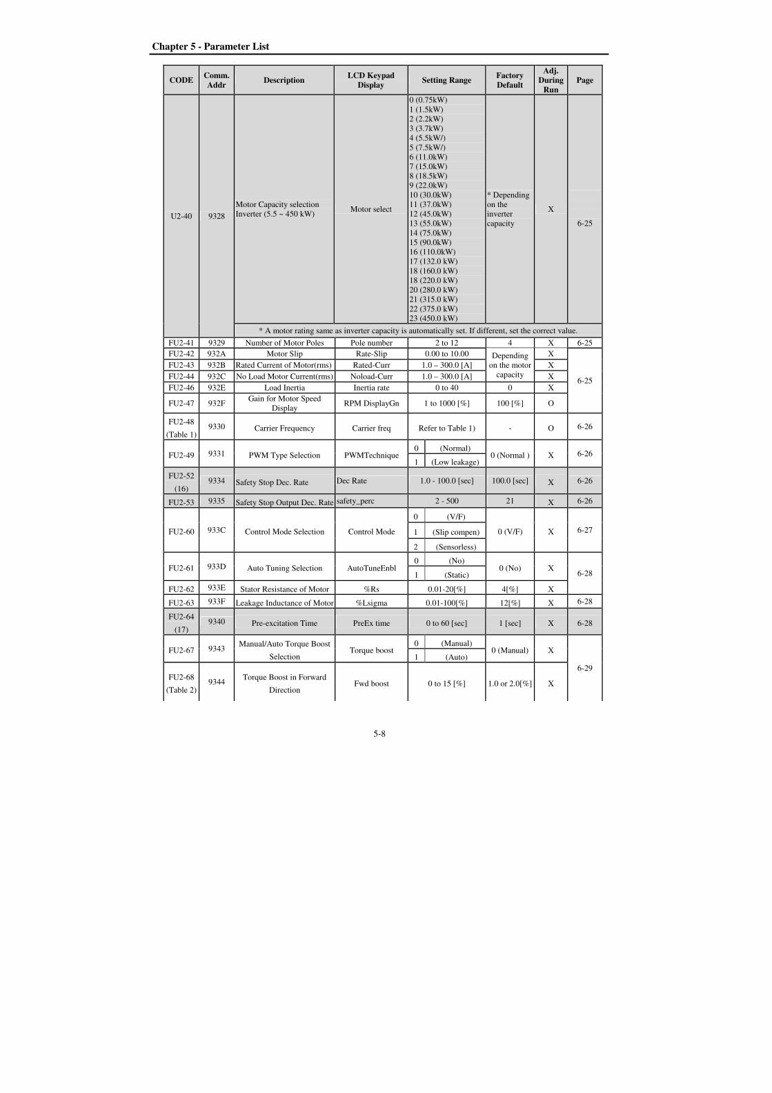
Chapter 5 - Parameter List
5-8
CODE Comm. Addr
Description LCD Keypad
Display Setting Range
Factory Default
Adj. During
Run Page
U2-40 9328
Motor Capacity selection
Inverter (5.5 ~ 450 kW) Motor select
0 (0.75kW)
1 (1.5kW)
2 (2.2kW)
3 (3.7kW)
4 (5.5kW/)
5 (7.5kW/)
6 (11.0kW)
7 (15.0kW)
8 (18.5kW)
9 (22.0kW)
10 (30.0kW)
11 (37.0kW)
12 (45.0kW)
13 (55.0kW)
14 (75.0kW)
15 (90.0kW)
16 (110.0kW)
17 (132.0 kW)
18 (160.0 kW)
18 (220.0 kW)
20 (280.0 kW)
21 (315.0 kW)
22 (375.0 kW)
23 (450.0 kW)
* Depending
on the
inverter
capacity
X
6-25
* A motor rating same as inverter capacity is automatically set. If different, set the correct value.
FU2-41 9329 Number of Motor Poles Pole number 2 to 12 4 X 6-25
FU2-42 932A Motor Slip Rate-Slip 0.00 to 10.00 Depending
on the motor
capacity
X
6-25
FU2-43 932B Rated Current of Motor(rms) Rated-Curr 1.0 – 300.0 [A] X
FU2-44 932C No Load Motor Current(rms) Noload-Curr 1.0 – 300.0 [A] X
FU2-46 932E Load Inertia Inertia rate 0 to 40 0 X
FU2-47 932F Gain for Motor Speed
Display RPM DisplayGn 1 to 1000 [%] 100 [%] O
FU2-48
(Table 1) 9330 Carrier Frequency Carrier freq Refer to Table 1) - O 6-26
FU2-49 9331 PWM Type Selection PWMTechnique 0 (Normal)
0 (Normal ) X 6-26 1 (Low leakage)
FU2-52
(16) 9334 Safety Stop Dec. Rate Dec Rate 1.0 - 100.0 [sec] 100.0 [sec] X 6-26
FU2-53 9335 Safety Stop Output Dec. Rate safety_perc 2 - 500 21 X 6-26
FU2-60 933C Control Mode Selection Control Mode
0 (V/F)
0 (V/F) X 6-27 1 (Slip compen)
2 (Sensorless)
FU2-61 933D Auto Tuning Selection AutoTuneEnbl 0 (No)
0 (No) X 6-28 1 (Static)
FU2-62 933E Stator Resistance of Motor %Rs 0.01-20[%] 4[%] X
FU2-63 933F Leakage Inductance of Motor %Lsigma 0.01-100[%] 12[%] X 6-28
FU2-64
(17) 9340 Pre-excitation Time PreEx time 0 to 60 [sec] 1 [sec] X 6-28
FU2-67 9343 Manual/Auto Torque Boost
Selection Torque boost
0 (Manual) 0 (Manual) X
6-29
1 (Auto)
FU2-68
(Table 2) 9344
Torque Boost in Forward
Direction Fwd boost 0 to 15 [%] 1.0 or 2.0[%] X
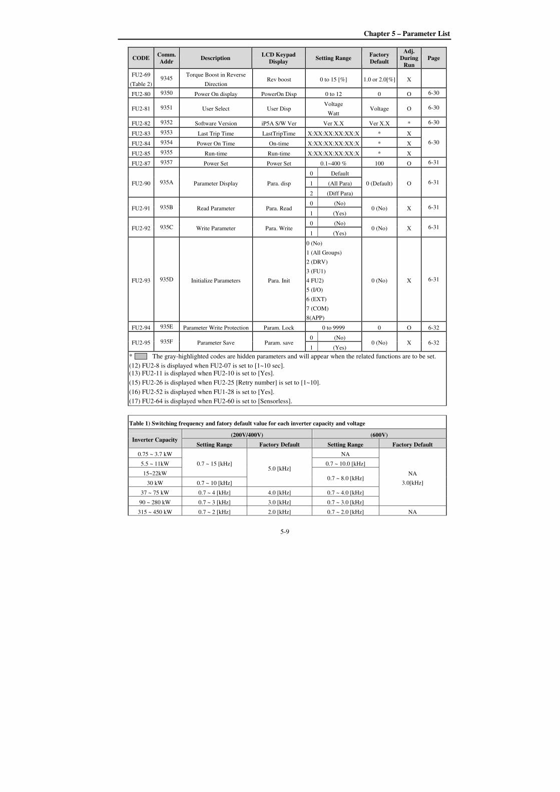
Chapter 5 – Parameter List
5-9
CODE Comm. Addr
Description LCD Keypad
Display Setting Range
Factory Default
Adj. During
Run Page
FU2-69
(Table 2) 9345
Torque Boost in Reverse
Direction Rev boost 0 to 15 [%] 1.0 or 2.0[%] X
FU2-80 9350 Power On display PowerOn Disp 0 to 12 0 O 6-30
FU2-81 9351 User Select User Disp Voltage
Watt Voltage O 6-30
FU2-82 9352 Software Version iP5A S/W Ver Ver X.X Ver X.X * 6-30
FU2-83 9353 Last Trip Time LastTripTime X:XX:XX:XX:XX:X * X
6-30 FU2-84 9354 Power On Time On-time X:XX:XX:XX:XX:X * X
FU2-85 9355 Run-time Run-time X:XX:XX:XX:XX:X * X
FU2-87 9357 Power Set Power Set 0.1~400 % 100 O 6-31
FU2-90 935A Parameter Display Para. disp
0 Default
0 (Default) O 6-31 1 (All Para)
2 (Diff Para)
FU2-91 935B Read Parameter Para. Read 0 (No)
0 (No) X 6-31 1 (Yes)
FU2-92 935C Write Parameter Para. Write 0 (No)
0 (No) X 6-31 1 (Yes)
FU2-93 935D Initialize Parameters Para. Init
0 (No)
1 (All Groups)
2 (DRV)
3 (FU1)
4 FU2)
5 (I/O)
6 (EXT)
7 (COM)
8(APP)
0 (No) X 6-31
FU2-94 935E Parameter Write Protection Param. Lock 0 to 9999 0 O 6-32
FU2-95 935F Parameter Save Param. save 0 (No)
0 (No) X 6-32 1 (Yes)
* The gray-highlighted codes are hidden parameters and will appear when the related functions are to be set.
(12) FU2-8 is displayed when FU2-07 is set to [1~10 sec].
(13) FU2-11 is displayed when FU2-10 is set to [Yes].
(15) FU2-26 is displayed when FU2-25 [Retry number] is set to [1~10].
(16) FU2-52 is displayed when FU1-28 is set to [Yes].
(17) FU2-64 is displayed when FU2-60 is set to [Sensorless].
Table 1) Switching frequency and fatory default value for each inverter capacity and voltage
Inverter Capacity (200V/400V) (600V)
Setting Range Factory Default Setting Range Factory Default
0.75 ~ 3.7 kW
0.7 ~ 15 [kHz] 5.0 [kHz]
NA
NA
3.0[kHz]
5.5 ~ 11kW 0.7 ~ 10.0 [kHz]
15~22kW 0.7 ~ 8.0 [kHz]
30 kW 0.7 ~ 10 [kHz]
37 ~ 75 kW 0.7 ~ 4 [kHz] 4.0 [kHz] 0.7 ~ 4.0 [kHz]
90 ~ 280 kW 0.7 ~ 3 [kHz] 3.0 [kHz] 0.7 ~ 3.0 [kHz]
315 ~ 450 kW 0.7 ~ 2 [kHz] 2.0 [kHz] 0.7 ~ 2.0 [kHz] NA

Chapter 5 - Parameter List
5-10
Table 2) Torque boost fatory default value for each inverter capacity and voltage
Inverter Capacity (200V/400V) (600V)
Setting Range Factory Default Setting Range Factory Default
0.75 ~ 3.7 kW
0 to 15[%]
2.0 [%]
0 to 15[%]
NA
5.5 ~ 11 kW 2[%]
15 ~ 90 kW 1[%]
110 kW 1.0 [%]
132 ~ 450 kW 1.0 [%] NA

Chapter 5 – Parameter List
5-11
[I/O GROUP]
CODE Comm. Addr
Description LCD Keypad
Display Setting Range
Factory Default
Adj. During
Run Page
I/O-00 9400 Jump to desired code Jump code 1 to 98 1 O 6-33
I/O-01
(17)
9401 Filtering Time Constant for
V1 Signal Input V1 Filter 0 to 9999 [msec] 10 [msec] O
6-33
I/O-02 9402 V1 Input Minimum Voltage V1 volt x1 0 to 12[V] 0.00 [V] O
I/O-03 9403 Frequency Corresponding to
V1 Input Minimum Voltage V1 Freq y1
0 to FU1-30 [Hz] 0.00 [Hz] O
0 to 100.00 [**](18)
I/O-04 9404 V1 Input Minimum Voltage V1 volt x2 0 to 12[V] 10 [V] O
I/O-05 9405 V1 Input Maximum Voltage V1 Freq y2 0 to FU1-30 [Hz]
60.00 [Hz] O 0 to 100.00 [**] (18)
I/O-06 9406 Filtering Time Constant for I
Signal Input I Filter 0 to 9999 [msec] 70 [msec] O
6-33
I/O-07 9407 I Input Minimum Current I curr x1 0 to 20 [mA] 4 [mA] O
I/O-08 9408 Frequency Corresponding to
I Input Minimum Current I Freq y1
0 to FU1-30 [Hz] 0.00 [Hz] O
0 to 100.00 [**](18)
I/O-09 9409 Filtering Time Constant for I
Signal Input I curr x2 0 to 20 [mA] 20 [mA] O
I/O-10 940A Frequency Corresponding to
I Input Maximum Current I Freq y2
0 to FU1-30 [Hz]
60.00 [Hz] O
0 to 100.00 [**](18)
I/O-11 940B Pulse input method P Pulse set 0 (A+B)
1 (A) O
6-34
1 (A)
I/O-12 940C Pulse input filter P filter 0 to 9999 [msec] 10 [msec] O
I/O-13 940D Pulse input Minimum
frequency P pulse x1 0 to 10 [kHz] 0 [kHz] O
I/O-14 940E
Frequency corresponding to
I/O-13 Pulse input Minimum
frequency
P freq y1
0 to FU1-30 [Hz]
0 [Hz] O
0 to 100.00 [**](18)
I/O-15 940F Pulse input Minimum
frequency P pulse x2 0 to 100 [kHz] 10 [kHz] O
I/O-16 9410
Frequency corresponding to
I/O-15 Pulse input Maximum
frequency
P freq y2
0 to FU1-30 [Hz]
60.00 [Hz] O 0 to 100.00 [**](18)
I/O-17 9411 Criteria for Analog Input
Signal Loss Wire broken
0 (None)
0 (None) O
6-35
1 (half of x1)
2 (below x1)
I/O-18 9412 Operating selection at Loss
of Freq. Reference Lost command
0 (None)
0 (None) O 1 (FreeRun)
2 (Stop)
3 (Protection)
I/O-19 9413 Waiting Time after Loss of
Freq. Reference Time out 0.1 to 120 [sec] 1.0 [sec] O
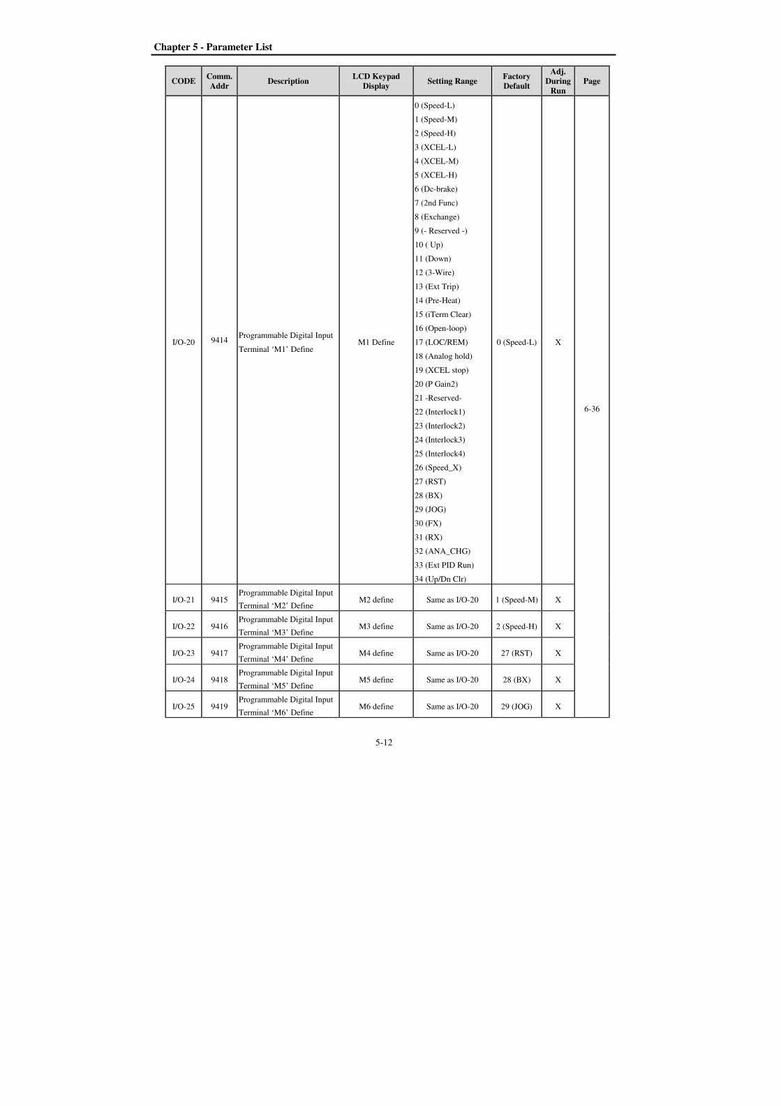
Chapter 5 - Parameter List
5-12
CODE Comm. Addr
Description LCD Keypad
Display Setting Range
Factory Default
Adj. During
Run Page
I/O-20 9414 Programmable Digital Input
Terminal ‘M1’ Define M1 Define
0 (Speed-L)
1 (Speed-M)
2 (Speed-H)
3 (XCEL-L)
4 (XCEL-M)
5 (XCEL-H)
6 (Dc-brake)
7 (2nd Func)
8 (Exchange)
9 (- Reserved -)
10 ( Up)
11 (Down)
12 (3-Wire)
13 (Ext Trip)
14 (Pre-Heat)
15 (iTerm Clear)
16 (Open-loop)
17 (LOC/REM)
18 (Analog hold)
19 (XCEL stop)
20 (P Gain2)
21 -Reserved-
22 (Interlock1)
23 (Interlock2)
24 (Interlock3)
25 (Interlock4)
26 (Speed_X)
27 (RST)
28 (BX)
29 (JOG)
30 (FX)
31 (RX)
32 (ANA_CHG)
33 (Ext PID Run)
34 (Up/Dn Clr)
0 (Speed-L) X
6-36
I/O-21 9415 Programmable Digital Input
Terminal ‘M2’ Define M2 define Same as I/O-20 1 (Speed-M) X
I/O-22 9416 Programmable Digital Input
Terminal ‘M3’ Define M3 define Same as I/O-20 2 (Speed-H) X
I/O-23 9417 Programmable Digital Input
Terminal ‘M4’ Define M4 define Same as I/O-20 27 (RST) X
I/O-24 9418 Programmable Digital Input
Terminal ‘M5’ Define M5 define Same as I/O-20 28 (BX) X
I/O-25 9419 Programmable Digital Input
Terminal ‘M6’ Define M6 define Same as I/O-20 29 (JOG) X
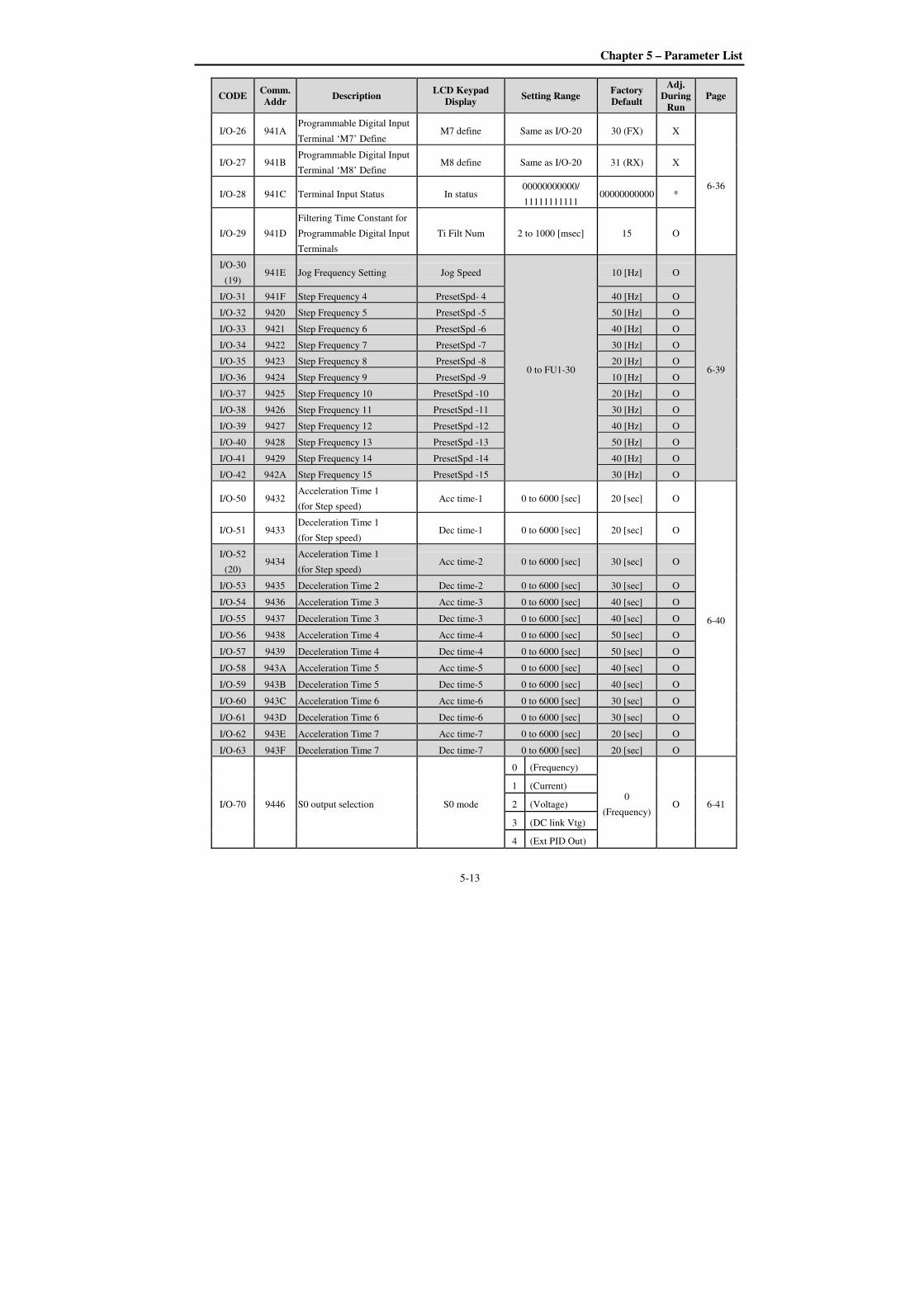
Chapter 5 – Parameter List
5-13
CODE Comm. Addr
Description LCD Keypad
Display Setting Range
Factory Default
Adj. During
Run Page
I/O-26 941A Programmable Digital Input
Terminal ‘M7’ Define M7 define Same as I/O-20 30 (FX) X
6-36
I/O-27 941B Programmable Digital Input
Terminal ‘M8’ Define M8 define Same as I/O-20 31 (RX) X
I/O-28 941C Terminal Input Status In status 00000000000/
11111111111 00000000000 *
I/O-29 941D
Filtering Time Constant for
Programmable Digital Input
Terminals
Ti Filt Num 2 to 1000 [msec] 15 O
I/O-30
(19) 941E Jog Frequency Setting Jog Speed
0 to FU1-30
10 [Hz] O
6-39
I/O-31 941F Step Frequency 4 PresetSpd- 4 40 [Hz] O
I/O-32 9420 Step Frequency 5 PresetSpd -5 50 [Hz] O
I/O-33 9421 Step Frequency 6 PresetSpd -6 40 [Hz] O
I/O-34 9422 Step Frequency 7 PresetSpd -7 30 [Hz] O
I/O-35 9423 Step Frequency 8 PresetSpd -8 20 [Hz] O
I/O-36 9424 Step Frequency 9 PresetSpd -9 10 [Hz] O
I/O-37 9425 Step Frequency 10 PresetSpd -10 20 [Hz] O
I/O-38 9426 Step Frequency 11 PresetSpd -11 30 [Hz] O
I/O-39 9427 Step Frequency 12 PresetSpd -12 40 [Hz] O
I/O-40 9428 Step Frequency 13 PresetSpd -13 50 [Hz] O
I/O-41 9429 Step Frequency 14 PresetSpd -14 40 [Hz] O
I/O-42 942A Step Frequency 15 PresetSpd -15 30 [Hz] O
I/O-50 9432 Acceleration Time 1
(for Step speed) Acc time-1 0 to 6000 [sec] 20 [sec] O
6-40
I/O-51 9433 Deceleration Time 1
(for Step speed) Dec time-1 0 to 6000 [sec] 20 [sec] O
I/O-52
(20) 9434
Acceleration Time 1
(for Step speed) Acc time-2 0 to 6000 [sec] 30 [sec] O
I/O-53 9435 Deceleration Time 2 Dec time-2 0 to 6000 [sec] 30 [sec] O
I/O-54 9436 Acceleration Time 3 Acc time-3 0 to 6000 [sec] 40 [sec] O
I/O-55 9437 Deceleration Time 3 Dec time-3 0 to 6000 [sec] 40 [sec] O
I/O-56 9438 Acceleration Time 4 Acc time-4 0 to 6000 [sec] 50 [sec] O
I/O-57 9439 Deceleration Time 4 Dec time-4 0 to 6000 [sec] 50 [sec] O
I/O-58 943A Acceleration Time 5 Acc time-5 0 to 6000 [sec] 40 [sec] O
I/O-59 943B Deceleration Time 5 Dec time-5 0 to 6000 [sec] 40 [sec] O
I/O-60 943C Acceleration Time 6 Acc time-6 0 to 6000 [sec] 30 [sec] O
I/O-61 943D Deceleration Time 6 Dec time-6 0 to 6000 [sec] 30 [sec] O
I/O-62 943E Acceleration Time 7 Acc time-7 0 to 6000 [sec] 20 [sec] O
I/O-63 943F Deceleration Time 7 Dec time-7 0 to 6000 [sec] 20 [sec] O
I/O-70 9446 S0 output selection S0 mode
0 (Frequency)
0
(Frequency) O 6-41
1 (Current)
2 (Voltage)
3 (DC link Vtg)
4 (Ext PID Out)
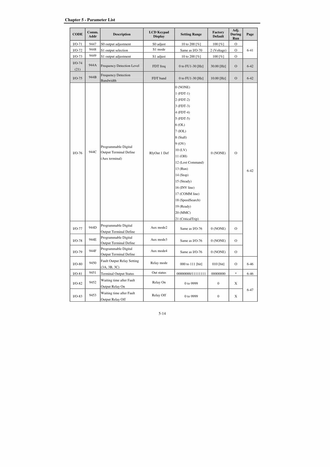
Chapter 5 - Parameter List
5-14
CODE Comm. Addr
Description LCD Keypad
Display Setting Range
Factory Default
Adj. During
Run Page
I/O-71 9447 S0 output adjustment S0 adjust 10 to 200 [%] 100 [%] O
6-41 I/O-72 9448 S1 output selection S1 mode Same as I/O-70 2 (Voltage) O
I/O-73 9449 S1 output adjustment S1 adjust 10 to 200 [%] 100 [%] O
I/O-74
(21)
944A Frequency Detection Level FDT freq 0 to FU1-30 [Hz] 30.00 [Hz] O 6-42
I/O-75 944B Frequency Detection
Bandwidth FDT band 0 to FU1-30 [Hz] 10.00 [Hz] O 6-42
I/O-76 944C
Programmable Digital
Output Terminal Define
(Aux terminal)
RlyOut 1 Def
0 (NONE)
1 (FDT-1)
2 (FDT-2)
3 (FDT-3)
4 (FDT-4)
5 (FDT-5)
6 (OL)
7 (IOL)
8 (Stall)
9 (OV)
10 (LV)
11 (OH)
12 (Lost Command)
13 (Run)
14 (Stop)
15 (Steady)
16 (INV line)
17 (COMM line)
18 (SpeedSearch)
19 (Ready)
20 (MMC)
21 (CriticalTrip)
0 (NONE) O
6-42
I/O-77 944D Programmable Digital
Output Terminal Define
Aux mode2 Same as I/O-76 0 (NONE) O
I/O-78 944E Programmable Digital
Output Terminal Define Aux mode3 Same as I/O-76 0 (NONE) O
I/O-79 944F Programmable Digital
Output Terminal Define Aux mode4 Same as I/O-76 0 (NONE) O
I/O-80 9450 Fault Output Relay Setting
(3A, 3B, 3C)
Relay mode 000 to 111 [bit] 010 [bit] O 6-46
I/O-81 9451 Terminal Output Status Out status 00000000/11111111 00000000 * 6-46
I/O-82 9452 Waiting time after Fault
Output Relay On
Relay On 0 to 9999 0 X
6-47
I/O-83 9453 Waiting time after Fault
Output Relay Off
Relay Off 0 to 9999 0 X
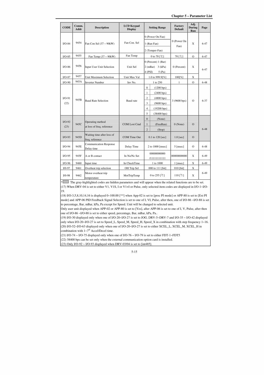
Chapter 5 – Parameter List
5-15
CODE Comm. Addr
Description LCD Keypad
Display Setting Range
Factory Default
Adj. During
Run Page
I/O-84 9454 Fan Con Sel (37 ~ 90kW) Fan Con. Sel
0 (Power On Fan)
0 (Power On
Fan) X 6-47 1 (Run Fan)
2 (Temper-Fan)
I/O-85 9455 Fan Temp (37 ~ 90kW) Fan Temp 0 to 70 [] 70 [] O 6-47
I/O-86 9456 Input User Unit Selection Unit Sel
0 (Percent) 1 (Bar)
2 (mBar) 3 (kPa)
4 (PSI) 5 (Pa)
0 (Percent) X 6-47
I/O-87 9457 Unit Maximum Selection Unit Max Val 1.0 to 999.9[%] 100[%] X
I/O-90 945A Inverter Number Inv No. 1 to 250 1 O 6-48
I/O-91
(22)
945B Baud Rate Selection Baud rate
0 (1200 bps)
3 (9600 bps) O 6-37
1 (2400 bps)
2 (4800 bps)
3 (9600 bps)
4 (19200 bps)
5 (38400 bps)
I/O-92
(23) 945C
Operating method
at loss of freq. reference COM Lost Cmd
0 (None)
0 (None) O
6-48
1 (FreeRun)
2 (Stop)
I/O-93 945D Waiting time after loss of
freq. reference COM Time Out 0.1 to 120 [sec] 1.0 [sec] O
I/O-94 945E Communication Response
Delay time Delay Time 2 to 1000 [msec] 5 [msec] O 6-48
I/O-95 945F A or B contact In No/Nc Set 00000000000
/11111111111 00000000000 X 6-49
I/O-96 9460 Input time In CheckTime 1 to 1000 1 [msec] X 6-49
I/0-97 9461 Overheat trip selection OH Trip Sel 000 to 111 [bit] 010 [bit] X
6-49 I/0-98 9462
Motor overheat trip
temperature MotTripTemp 0 to 255 [] 110 [] X
* The gray-highlighted codes are hidden parameters and will appear when the related functions are to be set.
(17) When DRV-04 is set to either V1, V1S, I or V1+I or Pulse, only selected item codes are displayed in I/O-1~I/O-
19.
(18) I/O-3,5,8,10,14,16 is displayed 0~100.00 [**] when App-02 is set to [proc PI mode] or APP-80 is set to [Ext PI
mode] and APP-06 PID Feedback Signal Selection is set to one of I, VI, Pulse, after then, one of I/O-86 ~I/O-88 is set
to percentage, Bar, mBar, kPa, Pa except for Speed. Unit will be changed to selected unit.
Only user unit displayed when APP-02 or APP-80 is set to [Yes], after APP-06 is set to one of I, V, Pulse, after then
one of I/O-86 ~I/O-88 is set to either speed, percentage, Bar, mBar, kPa, Pa..
(19) I/O-30 displayed only when one of I/O-20~I/O-27 is set to JOG. DRV-5~DRV-7 and I/O-35 ~ I/O-42 displayed
only when I/O-20~I/O-27 is set to Speed_L, Speed_M, Speed_H, Speed_X in combination with step frequency 1~16.
(20) I/O-52~I/O-63 displayed only when one of I/O-20~I/O-27 is set to either XCEL_L, XCEL_M, XCEL_H in
combination with 1~7th
Accel/Decel time.
(21) I/O-74 ~ I/O-75 displayed only when one of I/O-76 ~ I/O-79 is set to either FDT-1~FDT5
(22) 38400 bps can be set only when the external communication option card is installed.
(23) Only I/O-92 ~ I/O-93 displayed when DRV-03/04 is set to [int485].
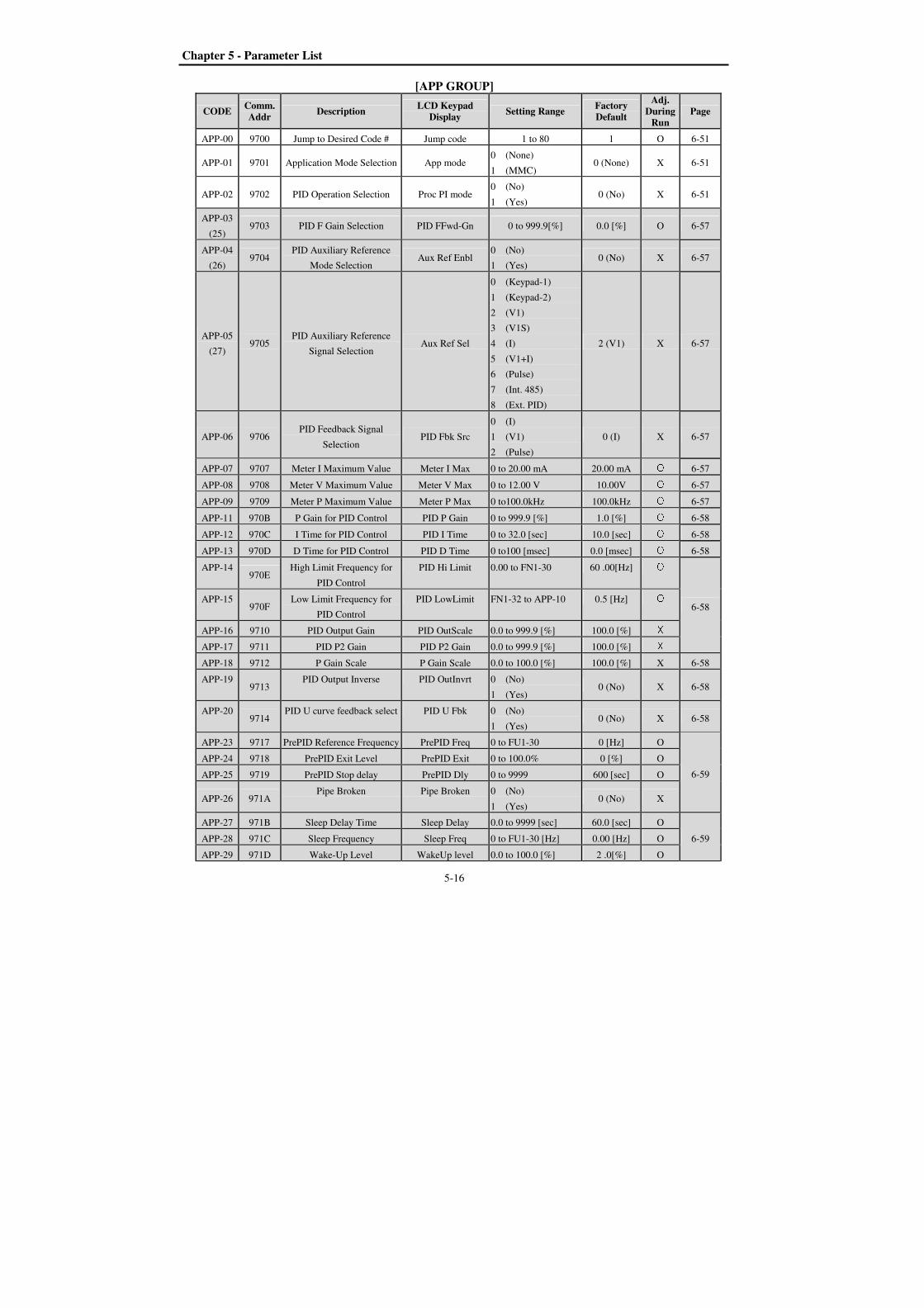
Chapter 5 - Parameter List
5-16
[APP GROUP]
CODE Comm. Addr
Description LCD Keypad
Display Setting Range
Factory Default
Adj. During
Run Page
APP-00 9700 Jump to Desired Code # Jump code 1 to 80 1 O 6-51
APP-01 9701 Application Mode Selection App mode 0 (None)
1 (MMC) 0 (None) X 6-51
APP-02 9702 PID Operation Selection Proc PI mode 0 (No)
1 (Yes) 0 (No) X 6-51
APP-03
(25) 9703 PID F Gain Selection PID FFwd-Gn 0 to 999.9[%] 0.0 [%] O 6-57
APP-04
(26) 9704
PID Auxiliary Reference
Mode Selection Aux Ref Enbl
0 (No)
1 (Yes) 0 (No) X 6-57
APP-05
(27) 9705
PID Auxiliary Reference
Signal Selection Aux Ref Sel
0 (Keypad-1)
1 (Keypad-2)
2 (V1)
3 (V1S)
4 (I)
5 (V1+I)
6 (Pulse)
7 (Int. 485)
8 (Ext. PID)
2 (V1) X 6-57
APP-06 9706 PID Feedback Signal
Selection PID Fbk Src
0 (I)
1 (V1)
2 (Pulse)
0 (I) X 6-57
APP-07 9707 Meter I Maximum Value Meter I Max 0 to 20.00 mA 20.00 mA O 6-57
APP-08 9708 Meter V Maximum Value Meter V Max 0 to 12.00 V 10.00V O 6-57
APP-09 9709 Meter P Maximum Value Meter P Max 0 to100.0kHz 100.0kHz O 6-57
APP-11 970B P Gain for PID Control PID P Gain 0 to 999.9 [%] 1.0 [%] O 6-58
APP-12 970C I Time for PID Control PID I Time 0 to 32.0 [sec] 10.0 [sec] O 6-58
APP-13 970D D Time for PID Control PID D Time 0 to100 [msec] 0.0 [msec] O 6-58
APP-14 970E
High Limit Frequency for
PID Control
PID Hi Limit 0.00 to FN1-30 60 .00[Hz] O 6-58
APP-15 970F
Low Limit Frequency for
PID Control
PID LowLimit FN1-32 to APP-10 0.5 [Hz] O APP-16 9710 PID Output Gain PID OutScale 0.0 to 999.9 [%] 100.0 [%] X APP-17 9711 PID P2 Gain PID P2 Gain 0.0 to 999.9 [%] 100.0 [%] X APP-18 9712 P Gain Scale P Gain Scale 0.0 to 100.0 [%] 100.0 [%] X 6-58
APP-19 9713
PID Output Inverse PID OutInvrt 0 (No)
1 (Yes) 0 (No) X 6-58
APP-20 9714
PID U curve feedback select PID U Fbk 0 (No)
1 (Yes) 0 (No) X 6-58
APP-23 9717 PrePID Reference Frequency PrePID Freq 0 to FU1-30 0 [Hz] O
6-59
APP-24 9718 PrePID Exit Level PrePID Exit 0 to 100.0% 0 [%] O
APP-25 9719 PrePID Stop delay PrePID Dly 0 to 9999 600 [sec] O
APP-26 971A Pipe Broken Pipe Broken 0 (No)
1 (Yes) 0 (No) X
APP-27 971B Sleep Delay Time Sleep Delay 0.0 to 9999 [sec] 60.0 [sec] O
6-59 APP-28 971C Sleep Frequency Sleep Freq 0 to FU1-30 [Hz] 0.00 [Hz] O
APP-29 971D Wake-Up Level WakeUp level 0.0 to 100.0 [%] 2 .0[%] O
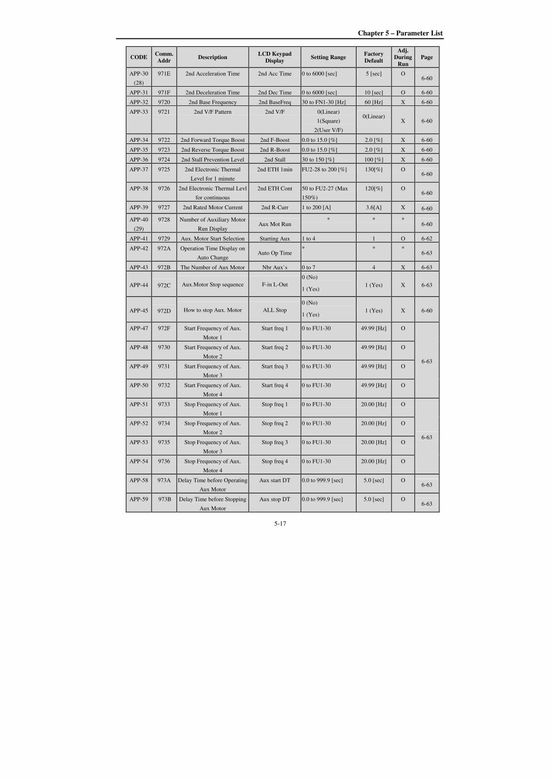
Chapter 5 – Parameter List
5-17
CODE Comm. Addr
Description LCD Keypad
Display Setting Range
Factory Default
Adj. During
Run Page
APP-30
(28)
971E 2nd Acceleration Time 2nd Acc Time 0 to 6000 [sec] 5 [sec] O 6-60
APP-31 971F 2nd Deceleration Time 2nd Dec Time 0 to 6000 [sec] 10 [sec] O 6-60
APP-32 9720 2nd Base Frequency 2nd BaseFreq 30 to FN1-30 [Hz] 60 [Hz] X 6-60
APP-33 9721 2nd V/F Pattern 2nd V/F 0(Linear)
1(Square)
2(User V/F)
0(Linear)
X 6-60
APP-34 9722 2nd Forward Torque Boost 2nd F-Boost 0.0 to 15.0 [%] 2.0 [%] X 6-60
APP-35 9723 2nd Reverse Torque Boost 2nd R-Boost 0.0 to 15.0 [%] 2.0 [%] X 6-60
APP-36 9724 2nd Stall Prevention Level 2nd Stall 30 to 150 [%] 100 [%] X 6-60
APP-37 9725 2nd Electronic Thermal
Level for 1 minute
2nd ETH 1min FU2-28 to 200 [%] 130[%] O 6-60
APP-38 9726 2nd Electronic Thermal Levl
for continuous
2nd ETH Cont 50 to FU2-27 (Max
150%)
120[%] O 6-60
APP-39 9727 2nd Rated Motor Current 2nd R-Curr 1 to 200 [A] 3.6[A] X 6-60
APP-40
(29)
9728 Number of Auxiliary Motor
Run Display Aux Mot Run
* * * 6-60
APP-41 9729 Aux. Motor Start Selection Starting Aux 1 to 4 1 O 6-62
APP-42 972A Operation Time Display on
Auto Change Auto Op Time
* * * 6-63
APP-43 972B The Number of Aux Motor Nbr Aux`s 0 to 7 4 X 6-63
APP-44 972C Aux.Motor Stop sequence F-in L-Out
0 (No)
1 (Yes) 1 (Yes) X 6-63
APP-45 972D How to stop Aux. Motor ALL Stop
0 (No)
1 (Yes) 1 (Yes) X 6-60
APP-47 972F Start Frequency of Aux.
Motor 1
Start freq 1 0 to FU1-30 49.99 [Hz] O
6-63
APP-48 9730 Start Frequency of Aux.
Motor 2
Start freq 2 0 to FU1-30 49.99 [Hz] O
APP-49 9731 Start Frequency of Aux.
Motor 3
Start freq 3 0 to FU1-30 49.99 [Hz] O
APP-50 9732 Start Frequency of Aux.
Motor 4
Start freq 4 0 to FU1-30 49.99 [Hz] O
APP-51 9733 Stop Frequency of Aux.
Motor 1
Stop freq 1 0 to FU1-30 20.00 [Hz] O
6-63
APP-52 9734 Stop Frequency of Aux.
Motor 2
Stop freq 2 0 to FU1-30 20.00 [Hz] O
APP-53 9735 Stop Frequency of Aux.
Motor 3
Stop freq 3 0 to FU1-30 20.00 [Hz] O
APP-54 9736 Stop Frequency of Aux.
Motor 4
Stop freq 4 0 to FU1-30 20.00 [Hz] O
APP-58 973A Delay Time before Operating
Aux Motor
Aux start DT 0.0 to 999.9 [sec] 5.0 [sec] O 6-63
APP-59 973B Delay Time before Stopping
Aux Motor
Aux stop DT 0.0 to 999.9 [sec] 5.0 [sec] O 6-63
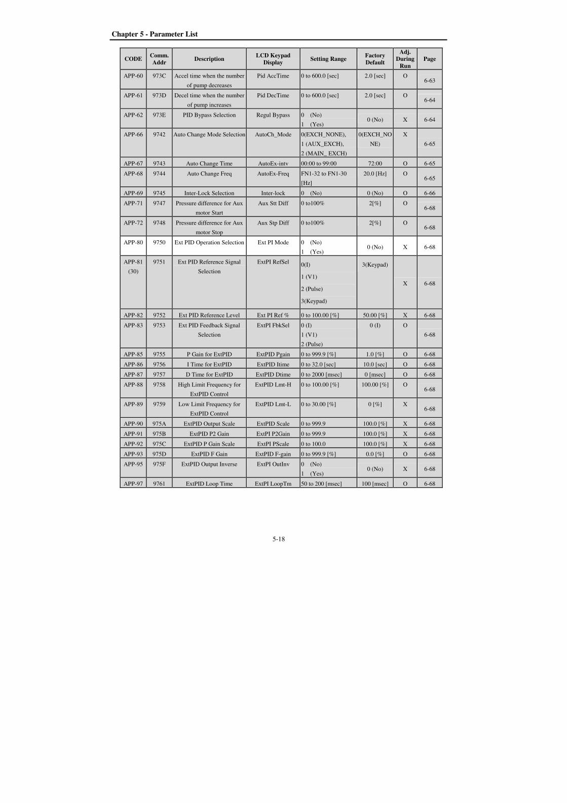
Chapter 5 - Parameter List
5-18
CODE Comm. Addr
Description LCD Keypad
Display Setting Range
Factory Default
Adj. During
Run Page
APP-60 973C Accel time when the number
of pump decreases
Pid AccTime 0 to 600.0 [sec] 2.0 [sec] O 6-63
APP-61 973D Decel time when the number
of pump increases
Pid DecTime 0 to 600.0 [sec] 2.0 [sec] O 6-64
APP-62 973E PID Bypass Selection Regul Bypass 0 (No)
1 (Yes) 0 (No) X 6-64
APP-66 9742 Auto Change Mode Selection AutoCh_Mode 0(EXCH_NONE),
1 (AUX_EXCH),
2 (MAIN_ EXCH)
0(EXCH_NO
NE)
X
6-65
APP-67 9743 Auto Change Time AutoEx-intv 00:00 to 99:00 72:00 O 6-65
APP-68 9744 Auto Change Freq AutoEx-Freq FN1-32 to FN1-30
[Hz]
20.0 [Hz] O 6-65
APP-69 9745 Inter-Lock Selection Inter-lock 0 (No) 0 (No) O 6-66
APP-71 9747 Pressure difference for Aux
motor Start
Aux Stt Diff 0 to100% 2[%] O 6-68
APP-72 9748 Pressure difference for Aux
motor Stop
Aux Stp Diff 0 to100% 2[%] O 6-68
APP-80 9750 Ext PID Operation Selection Ext PI Mode 0 (No)
1 (Yes) 0 (No) X 6-68
APP-81
(30)
9751 Ext PID Reference Signal
Selection
ExtPI RefSel 0(I)
1 (V1)
2 (Pulse)
3(Keypad)
3(Keypad)
X 6-68
APP-82 9752 Ext PID Reference Level Ext PI Ref % 0 to 100.00 [%] 50.00 [%] X 6-68
APP-83 9753 Ext PID Feedback Signal
Selection
ExtPI FbkSel 0 (I)
1 (V1)
2 (Pulse)
0 (I) O
6-68
APP-85 9755 P Gain for ExtPID ExtPID Pgain 0 to 999.9 [%] 1.0 [%] O 6-68
APP-86 9756 I Time for ExtPID ExtPID Itime 0 to 32.0 [sec] 10.0 [sec] O 6-68
APP-87 9757 D Time for ExtPID ExtPID Dtime 0 to 2000 [msec] 0 [msec] O 6-68
APP-88 9758 High Limit Frequency for
ExtPID Control
ExtPID Lmt-H 0 to 100.00 [%] 100.00 [%] O 6-68
APP-89 9759 Low Limit Frequency for
ExtPID Control
ExtPID Lmt-L 0 to 30.00 [%] 0 [%] X 6-68
APP-90 975A ExtPID Output Scale ExtPID Scale 0 to 999.9 100.0 [%] X 6-68
APP-91 975B ExtPID P2 Gain ExtPI P2Gain 0 to 999.9 100.0 [%] X 6-68
APP-92 975C ExtPID P Gain Scale ExtPI PScale 0 to 100.0 100.0 [%] X 6-68
APP-93 975D ExtPID F Gain ExtPID F-gain 0 to 999.9 [%] 0.0 [%] O 6-68
APP-95 975F ExtPID Output Inverse ExtPI OutInv 0 (No)
1 (Yes) 0 (No) X 6-68
APP-97 9761 ExtPID Loop Time ExtPI LoopTm 50 to 200 [msec] 100 [msec] O 6-68

Chapter 5 – Parameter List
5-19
CODE Comm. Addr
Description LCD Keypad
Display Setting Range
Factory Default
Adj. During
Run Page
* The gray highlighted codes are hidden parameters and will appear when the related functions are to be set.
(25) Only APP-03 ~ APP-04 displayed when APP-02 is set to [Yes].
Only APP-06 ~ APP-17 and APP-63 ~ APP-65 displayed when APP-2 is set to [Yes]
Only APP-05 displayed when APP-04 is set to [Yes]
(26) If APP-04 Aux Ref Mode is no set, DRV-04 setting will be reference of process PID. And APP -05 setting will
be ignored
(27) If APP-04 is set, APP-05 will appear. And APP -05 setting value will be reference of process PID, DRV-04
setting will be ignored.
(28) Only APP-20 ~ APP-29 displayed only when one of I/O-20 ~ I/O-27 is set to either “2nd Func”.
(29) Only APP-40 ~ APP-71 displayed when APP-01 is set to [MMC].
(30) Only APP-81 ~ APP-97 displayed when APP-80 Ext PI mode is set to [Yes].
[EXT GROUP]
CODE Comm. Addr
Description LCD Keypad
Display Setting Range
Factory Default
Adj. During
Run Page
EXT-00 9500 Jump Code Jump code 1 to 45 1 O
Refer to
the
correspo-
nding
option
manual
EXT-01 9501 Type of SUB Board Sub B/D Sub-E * *
EXT-40 9528 Current Output Terminal
1(CO1) Selection AM1 mode
Frequency
Current
Voltage
DC link Vtg
Ext PID Out
Frequency O
EXT-41 9529 Adjust Gain of Current
Output Terminal 1(CO1) AM1 adjust 10 – 200 [%] 100 [%] O
EXT-42 952A Adjust Offset of Current
Output Terminal 1(CO1) AM1 Offset 0 – 100 [%] 0 [%] O
EXT-43 952B Current Output Terminal
2(CO2) Selection AM2 mode
Frequency
Current
Voltage
DC link Vtg
Ext PID Out
DC link Vtg O
EXT-44 952C Adjust Gain of Current
Output Terminal 2(CO2) AM2 adjust 10 – 200 [%] 100 [%] O
EXT-45 952D Adjust Offset of Current
Output Terminal 2(CO2) AM2 Offset
0 – 100 [%] 0 [%] O
* Only the above EXT group displayed when the corresponding option board is installed.
* Refer to the SUB board option manual for details.
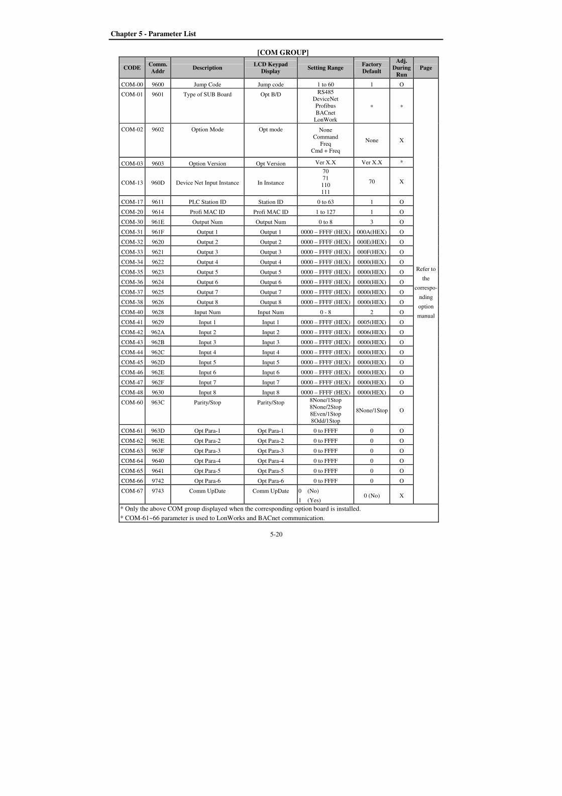
Chapter 5 - Parameter List
5-20
[COM GROUP]
CODE Comm. Addr
Description LCD Keypad
Display Setting Range
Factory Default
Adj. During
Run Page
COM-00 9600 Jump Code Jump code 1 to 60 1 O
Refer to
the
correspo-
nding
option
manual
COM-01 9601 Type of SUB Board Opt B/D RS485
DeviceNet
Profibus
BACnet
LonWork
* *
COM-02 9602 Option Mode Opt mode None
Command
Freq
Cmd + Freq
None X
COM-03 9603 Option Version Opt Version Ver X.X Ver X.X *
COM-13 960D Device Net Input Instance In Instance
70
71
110
111
70 X
COM-17 9611 PLC Station ID Station ID 0 to 63 1 O
COM-20 9614 Profi MAC ID Profi MAC ID 1 to 127 1 O
COM-30 961E Output Num Output Num 0 to 8 3 O
COM-31 961F Output 1 Output 1 0000 – FFFF (HEX) 000A(HEX) O
COM-32 9620 Output 2 Output 2 0000 – FFFF (HEX) 000E(HEX) O
COM-33 9621 Output 3 Output 3 0000 – FFFF (HEX) 000F(HEX) O
COM-34 9622 Output 4 Output 4 0000 – FFFF (HEX) 0000(HEX) O
COM-35 9623 Output 5 Output 5 0000 – FFFF (HEX) 0000(HEX) O
COM-36 9624 Output 6 Output 6 0000 – FFFF (HEX) 0000(HEX) O
COM-37 9625 Output 7 Output 7 0000 – FFFF (HEX) 0000(HEX) O
COM-38 9626 Output 8 Output 8 0000 – FFFF (HEX) 0000(HEX) O
COM-40 9628 Input Num Input Num 0 - 8 2 O
COM-41 9629 Input 1 Input 1 0000 – FFFF (HEX) 0005(HEX) O
COM-42 962A Input 2 Input 2 0000 – FFFF (HEX) 0006(HEX) O
COM-43 962B Input 3 Input 3 0000 – FFFF (HEX) 0000(HEX) O
COM-44 962C Input 4 Input 4 0000 – FFFF (HEX) 0000(HEX) O
COM-45 962D Input 5 Input 5 0000 – FFFF (HEX) 0000(HEX) O
COM-46 962E Input 6 Input 6 0000 – FFFF (HEX) 0000(HEX) O
COM-47 962F Input 7 Input 7 0000 – FFFF (HEX) 0000(HEX) O
COM-48 9630 Input 8 Input 8 0000 – FFFF (HEX) 0000(HEX) O
COM-60 963C Parity/Stop Parity/Stop 8None/1Stop
8None/2Stop
8Even/1Stop
8Odd/1Stop
8None/1Stop
O
COM-61 963D Opt Para-1 Opt Para-1 0 to FFFF 0 O
COM-62 963E Opt Para-2 Opt Para-2 0 to FFFF 0 O
COM-63 963F Opt Para-3 Opt Para-3 0 to FFFF 0 O
COM-64 9640 Opt Para-4 Opt Para-4 0 to FFFF 0 O
COM-65 9641 Opt Para-5 Opt Para-5 0 to FFFF 0 O
COM-66 9742 Opt Para-6 Opt Para-6 0 to FFFF 0 O
COM-67 9743 Comm UpDate Comm UpDate 0 (No)
1 (Yes) 0 (No) X
* Only the above COM group displayed when the corresponding option board is installed.
* COM-61~66 parameter is used to LonWorks and BACnet communication.
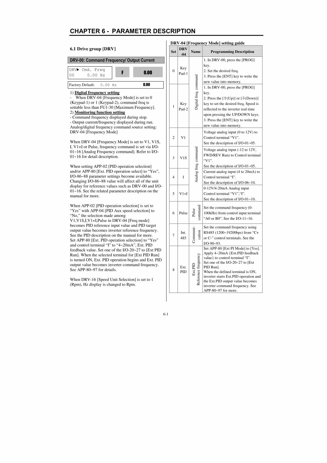
6-1
CHAPTER 6 - PARAMETER DESCRIPTION
6.1 Drive group [DRV]
DRV-00: Command Frequency/ Output Current
1) Digital frequency setting
- When DRV-04 [Frequency Mode] is set to 0
(Keypad-1) or 1 (Keypad-2), command freq is
settable less than FU1-30 [Maximum Frequency].
2) Monitoring function setting
- Command frequency displayed during stop.
- Output current/frequency displayed during run.
Analog/digital frequency command source setting:
DRV-04 [Frequency Mode]
When DRV-04 [Frequency Mode] is set to V1, V1S,
I, V1+I or Pulse, frequency command is set via I/O-
01~16 [Analog Frequency command]. Refer to I/O-
01~16 for detail description.
When setting APP-02 [PID operation selection]
and/or APP-80 [Ext. PID operation select] to “Yes”,
I/O-86~88 parameter settings become available.
Changing I/O-86~88 value will affect all of the unit
display for reference values such as DRV-00 and I/O-
01~16. See the related parameter description on the
manual for more.
When APP-02 [PID operation selection] is set to
“Yes” with APP-04 [PID Aux speed selection] to
“No,” the selection made among
V1,V1S,I,V1+I,Pulse in DRV-04 [Freq mode]
becomes PID reference input value and PID target
output value becomes inverter reference frequency.
See the PID description on the manual for more.
Set APP-80 [Ext. PID operation selection] to “Yes”
and control terminal “I” to “4~20mA”, Ext. PID
feedback value. Set one of the I/O-20~27 to [Ext PID
Run]. When the selected terminal for [Ext PID Run]
is turned ON, Ext. PID operation begins and Ext. PID
output value becomes inverter command frequency.
See APP-80~97 for details.
When DRV-16 [Speed Unit Selection] is set to 1
(Rpm), Hz display is changed to Rpm.
DRV-04 [Frequency Mode] setting guide
Set DRV
-04 Name Programming Description
0 Key
Pad-1
Dig
ital
fre
q.
com
man
d
1. In DRV-00, press the [PROG]
key.
2. Set the desired freq.
3. Press the [ENT] key to write the
new value into memory.
1 Key
Pad-2
1. In DRV-00, press the [PROG]
key.
2. Press the [(Up)] or [(Down)]
key to set the desired freq. Speed is
reflected to the inverter real time
upon pressing the UP/DOWN keys.
3. Press the [ENT] key to write the
new value into memory.
2 V1
An
alo
g f
req
. co
mm
and
Voltage analog input (0 to 12V) to
Control terminal “V1”.
See the description of I/O-01~05.
3 V1S
Voltage analog input (-12 to 12V,
FWD/REV Run) to Control terminal
“V1”.
See the description of I/O-01~05.
4 I
Current analog input (4 to 20mA) to
Control terminal “I”.
See the description of I/O-06~10.
5 V1+I
0-12V/4-20mA Analog input
Control terminal “V1”,“I”.
See the description of I/O-01~10.
6 Pulse
Pu
lse
com
man
d
Set the command frequency (0-
100kHz) from control input terminal
“A0 or B0”. See the I/O-11~16.
7 Int.
485
Co
mm
un
i-
cati
on
Set the command frequency using
RS485 (1200~19200bps) from “C+
or C-” control terminals. See the
I/O-90~93.
8 Ext.
PID
Ex
t.P
ID
Ref
eren
ce f
requ
ency
Set APP-80 [Ext PI Mode] to [Yes].
Apply 4~20mA Ext.PID feedback
value to control terminal “I”.
Set one of the I/O-20~27 to [Ext
PID Run].
When the defined terminal is ON,
inverter starts Ext.PID operation and
the Ext.PID output value becomes
inverter command frequency. See
APP-80~97 for more.
DRV Cmd. Freq
00 0.00 Hz 0.00
F
Factory Default: 0.00 Hz 0.00

Chapter 6 - Parameter Description [DRV]
6-2
DRV-01, 02: Accel/Decel Time 0
The inverter targets FU1-73 when accelerating or
decelerating. When FU1-73 is set to “Maximum
Frequency”, the acceleration time is the time taken by
the motor to reach FU1-30 from 0 Hz. The
deceleration time is the time taken by the motor to
reach 0 Hz from FU1-30 [Maximum Frequency].
When FU1-73 is set to “Delta Frequency”, the
acceleration and deceleration time is the time taken to
reach a target frequency (instead the maximum
frequency) from a specific frequency.
The acceleration and deceleration time can be
changed to a preset time via Programmable digital
inputs. By setting M1~M8 to ‘XCEL-L’, ‘XCEL-M’,
‘XCEL-H’ respectively, the 1~7 Accel and Decel
time set in I/O-50 to I/O-63 are applied by the binary
inputs of the M1~M8.
Note: Set the Accel time more than 0.5 sec for smooth
acceleration. Setting it too short may deteriorate the
starting performance.
In case of the inverters for 110~450kW(150~600HP), the
factory default of Accel/Decel Time is 60.0/90.0[sec]
respectively.
Code LCD
display Name
XCEL
-H
XCEL
-M
XCEL
-L Default
DRV-01 Acc time Acc time 0 0 0 0 20 sec
DRV-02 Dec time Dec time 0 0 0 0 30 sec
I/O-50 ACC-1 Acc time 1 0 0 1 20 sec
I/O-51 DEC-1 Dec time 1 0 0 1 20 sec
I/O-52 ACC-2 Acc time 2 0 1 0 30 sec
I/O-53 DEC-2 Dec time 2 0 1 0 30 sec
I/O-54 ACC-3 Acc time 3 0 1 1 40 sec
I/O-55 DEC-3 Dec time 3 0 1 1 40 sec
I/O-56 ACC-4 Acc time 4 1 0 0 50 sec
I/O-57 DEC-4 Dec time 4 1 0 0 50 sec
Code LCD
display Name
XCEL
-H
XCEL
-M
XCEL
-L Default
I/O-58 ACC-5 Acc time 5 1 0 1 40 sec
I/O-59 DEC-5 Dec time 5 1 0 1 40 sec
I/O-60 ACC-6 Acc time 6 1 1 0 30 sec
I/O-61 DEC-6 Dec time 6 1 1 0 30 sec
I/O-62 ACC-7 Acc time 7 1 1 1 20 sec
I/O-63 DEC-7 Dec time 7 1 1 1 20 sec
FU1-73 [Reference Frequency for Accel and Decel]
Set the reference frequency for Accel/Decel time. It
can be changed depending on the application.
Setting Range Description
Max freq
The Accel/Decel time is the time
that takes to reach the maximum
frequency from 0 Hz.
Delta freq
The Accel/Decel time is the time
that takes to reach a target
frequency from any frequency.
FU1-74 [Accel/Decel time scale]
Set the Accel/Decel time unit.
Setting Unit Description
0 0.01 sec Minimum 0 sec settable
Maximum 60 sec settable
1 0.1 sec
Minimum 0 sec settable
Maximum 600 sec settable
(Factory setting)
2 1 sec Minimum 0 sec settable
Maximum 6000 sec settable*
DRV-03: Drive Mode (Run/Stop Method)
Select the source of run/stop command.
Setting Range Description
Keypad Run/Stop control by Keypad.
Fx/Rx-1
Run/Stop control by Control
Terminals command FX, RX.
(Method 1)
FX: Forward Run/Stop
RX: Reverse Run/Stop
Fx/Rx-2
Run/Stop control by Control
Terminals FX, RX. (Method 2)
FX: Run/Stop command
DRV Acc. time
01 20.0 sec 20.0
01
Factory Default: 20.0 sec 20.0
DRV Dec. time
02 30.0 sec 30.0
02
Factory Default: 30.0 sec 30.0
DRV Drive mode
03 Fx/Rx-1 1
03
Factory Default: Fx/Rx-1 1
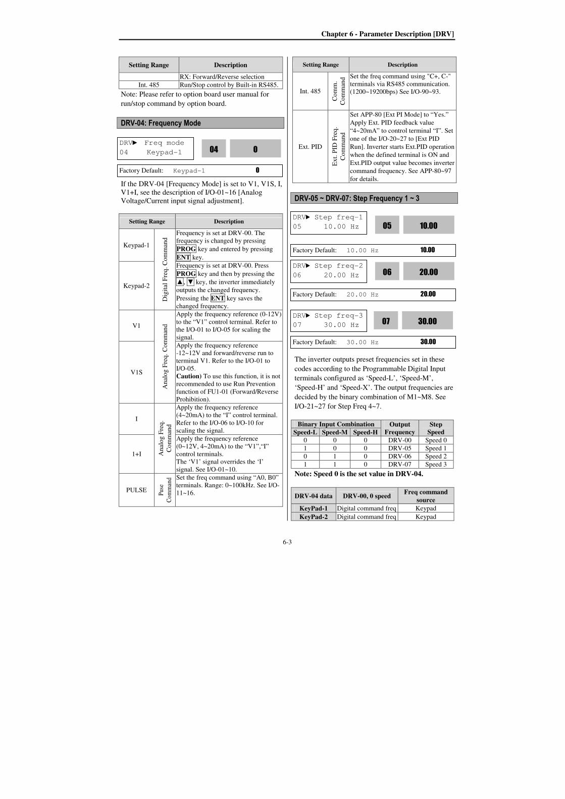
Chapter 6 - Parameter Description [DRV]
6-3
Setting Range Description
RX: Forward/Reverse selection
Int. 485 Run/Stop control by Built-in RS485.
Note: Please refer to option board user manual for
run/stop command by option board.
DRV-04: Frequency Mode
If the DRV-04 [Frequency Mode] is set to V1, V1S, I,
V1+I, see the description of I/O-01~16 [Analog
Voltage/Current input signal adjustment].
Setting Range Description
Keypad-1
Dig
ital
Fre
q.
Co
mm
and
Frequency is set at DRV-00. The
frequency is changed by pressing
PROG key and entered by pressing
ENT key.
Keypad-2
Frequency is set at DRV-00. Press
PROG key and then by pressing the
, key, the inverter immediately
outputs the changed frequency.
Pressing the ENT key saves the
changed frequency.
V1
An
alo
g F
req
. C
om
man
d
Apply the frequency reference (0-12V)
to the “V1” control terminal. Refer to
the I/O-01 to I/O-05 for scaling the
signal.
V1S
Apply the frequency reference
-12~12V and forward/reverse run to
terminal V1. Refer to the I/O-01 to
I/O-05.
Caution) To use this function, it is not
recommended to use Run Prevention
function of FU1-01 (Forward/Reverse
Prohibition).
I
An
alo
g F
req
.
Co
mm
and
Apply the frequency reference
(4~20mA) to the “I” control terminal.
Refer to the I/O-06 to I/O-10 for
scaling the signal.
1+I
Apply the frequency reference
(0~12V, 4~20mA) to the “V1”,“I”
control terminals.
The ‘V1’ signal overrides the ‘I’
signal. See I/O-01~10.
PULSE
Pus
e
Co
mm
and
Set the freq command using “A0, B0”
terminals. Range: 0~100kHz. See I/O-
11~16.
Setting Range Description
Int. 485
Co
mm
.
Co
mm
and Set the freq command using "C+, C-"
terminals via RS485 communication.
(1200~19200bps) See I/O-90~93.
Ext. PID
Ex
t. P
ID F
req
.
Co
mm
and
Set APP-80 [Ext PI Mode] to “Yes.”
Apply Ext. PID feedback value
“4~20mA” to control terminal “I”. Set
one of the I/O-20~27 to [Ext PID
Run]. Inverter starts Ext.PID operation
when the defined terminal is ON and
Ext.PID output value becomes inverter
command frequency. See APP-80~97
for details.
DRV-05 ~ DRV-07: Step Frequency 1 ~ 3
The inverter outputs preset frequencies set in these
codes according to the Programmable Digital Input
terminals configured as ‘Speed-L’, ‘Speed-M’,
‘Speed-H’ and ‘Speed-X’. The output frequencies are
decided by the binary combination of M1~M8. See
I/O-21~27 for Step Freq 4~7.
Binary Input Combination Output
Frequency Step
Speed Speed-L Speed-M Speed-H
0 0 0 DRV-00 Speed 0
1 0 0 DRV-05 Speed 1
0 1 0 DRV-06 Speed 2
1 1 0 DRV-07 Speed 3
Note: Speed 0 is the set value in DRV-04.
DRV-04 data DRV-00, 0 speed Freq command
source
KeyPad-1 Digital command freq Keypad
KeyPad-2 Digital command freq Keypad
DRV Step freq-1
05 10.00 Hz 10.00
05
Factory Default: 10.00 Hz 10.00
DRV Step freq-2
06 20.00 Hz 20.00
06
Factory Default: 20.00 Hz 20.00
DRV Step freq-3
07 30.00 Hz 30.00
07
Factory Default: 30.00 Hz 30.00
DRV Freq mode
04 Keypad-1 0
04
Factory Default: Keypad-1 0

Chapter 6 - Parameter Description [DRV]
6-4
DRV-04 data DRV-00, 0 speed Freq command
source
V1 Analog command
freq Terminal
V1S Analog command
freq Terminal
I Analog command
freq Terminal
V1+I Analog command
freq Terminal
Pulse Pulse command freq Terminal
Int. 485 Comm. command
freq Terminal
Ext. PID Ext.PID reference
frequency
Keypad or
Terminal
DRV-08: Output Current
This code displays the output current of the inverter
in rms unit.
DRV-09: Motor RPM
This code displays the motor speed in RPM while the
motor is running. Use the following equation to scale
the mechanical speed using FU2-47 [Gain for Motor
Speed display] if you want to change the motor speed
display to rotation speed (r/min) or mechanical speed
(m/min).
Motor speed = 120 * (F/P) * Gain for Motor Speed
display [FU2-47].
Where, F= Output Frequency and P= the Number of
Motor Poles
DRV-10: DC Link Voltage
This code displays the DC link voltage inside the
inverter.
DRV-11: User Display Selection
This code displays the parameter selected in FU2-81
[User Display]. One of Voltage (factory default,
output voltage display) or Watt (output power display)
is selectable.
DRV-12: Current Trip Display
This code displays the current fault (trip) status of the
inverter. Use the PROG, and key before
pressing the RESET key to check the fault content(s),
output frequency, output current, and whether the
inverter was accelerating, decelerating, or in constant
speed at the time of the fault occurred. Press the
ENT key to exit. The fault content will be stored in
FU2-01 to FU2-05 when the RESET key is pressed.
For more detail, please refer to Chapter 7.
Troubleshooting and Maintenance.
[Fault Contents]
Fault (Trip) LCD Keypad display
Over-Current 1 Over Current 1
Over-Voltage Over Voltage
External Trip Input Ext. Trip
Emergency Stop
(Not Latched) BX
Low-Voltage Low Voltage
Ground Fault Ground Fault
Over-Heat on Heat sink Over Heat
Electronic Thermal Trip E-Thermal
Over-Load Trip Over Load
Inverter H/W Fault
- EEP Error, ADC Offset,
WDOG Error, In-Phase
Open, No Motor Trip
HW-Diag
Over-Current 2 Over Current 2
Output Phase Loss Out Phase Open
Inverter Over-Load Inv. OLT
DRV Fault
12 None nOn
12
Factory Default: None nOn
DRV Current
08 0.0 A 0.0
08
Factory Default: 0.0 A 0.0
DRV Speed
09 0rpm 0
09
Factory Default: 0rmp 0
DRV DC link vtg
10 ----- V ----
10
Factory Default: ---- V ----
DRV User disp
11 0.0 V 0.0
11
Factory Default: 0.0 V 0.0
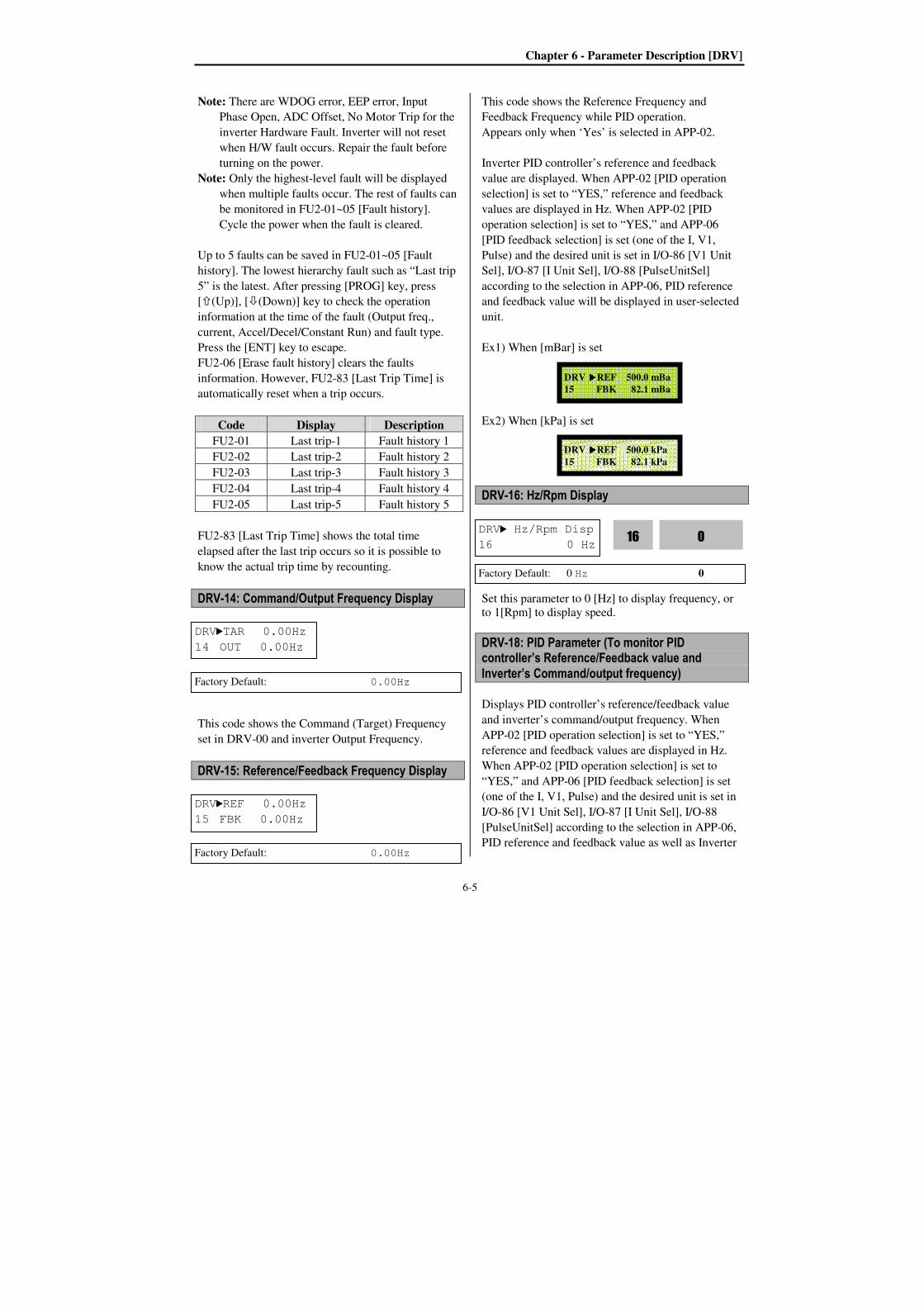
Chapter 6 - Parameter Description [DRV]
6-5
Note: There are WDOG error, EEP error, Input
Phase Open, ADC Offset, No Motor Trip for the
inverter Hardware Fault. Inverter will not reset
when H/W fault occurs. Repair the fault before
turning on the power.
Note: Only the highest-level fault will be displayed
when multiple faults occur. The rest of faults can
be monitored in FU2-01~05 [Fault history].
Cycle the power when the fault is cleared.
Up to 5 faults can be saved in FU2-01~05 [Fault
history]. The lowest hierarchy fault such as “Last trip
5” is the latest. After pressing [PROG] key, press
[(Up)], [(Down)] key to check the operation
information at the time of the fault (Output freq.,
current, Accel/Decel/Constant Run) and fault type.
Press the [ENT] key to escape.
FU2-06 [Erase fault history] clears the faults
information. However, FU2-83 [Last Trip Time] is
automatically reset when a trip occurs.
Code Display Description
FU2-01 Last trip-1 Fault history 1
FU2-02 Last trip-2 Fault history 2
FU2-03 Last trip-3 Fault history 3
FU2-04 Last trip-4 Fault history 4
FU2-05 Last trip-5 Fault history 5
FU2-83 [Last Trip Time] shows the total time
elapsed after the last trip occurs so it is possible to
know the actual trip time by recounting.
DRV-14: Command/Output Frequency Display
This code shows the Command (Target) Frequency
set in DRV-00 and inverter Output Frequency.
DRV-15: Reference/Feedback Frequency Display
This code shows the Reference Frequency and
Feedback Frequency while PID operation.
Appears only when ‘Yes’ is selected in APP-02.
Inverter PID controller’s reference and feedback
value are displayed. When APP-02 [PID operation
selection] is set to “YES,” reference and feedback
values are displayed in Hz. When APP-02 [PID
operation selection] is set to “YES,” and APP-06
[PID feedback selection] is set (one of the I, V1,
Pulse) and the desired unit is set in I/O-86 [V1 Unit
Sel], I/O-87 [I Unit Sel], I/O-88 [PulseUnitSel]
according to the selection in APP-06, PID reference
and feedback value will be displayed in user-selected
unit.
Ex1) When [mBar] is set Ex2) When [kPa] is set DRV-16: Hz/Rpm Display
Set this parameter to 0 [Hz] to display frequency, or
to 1[Rpm] to display speed.
DRV-18: PID Parameter (To monitor PID controller’s Reference/Feedback value and
Inverter’s Command/output frequency)
Displays PID controller’s reference/feedback value
and inverter’s command/output frequency. When
APP-02 [PID operation selection] is set to “YES,”
reference and feedback values are displayed in Hz.
When APP-02 [PID operation selection] is set to
“YES,” and APP-06 [PID feedback selection] is set
(one of the I, V1, Pulse) and the desired unit is set in
I/O-86 [V1 Unit Sel], I/O-87 [I Unit Sel], I/O-88
[PulseUnitSel] according to the selection in APP-06,
PID reference and feedback value as well as Inverter
DRVTAR 0.00Hz
14 OUT 0.00Hz
Factory Default: 0.00Hz
DRVREF 0.00Hz
15 FBK 0.00Hz
Factory Default: 0.00Hz
DRV Hz/Rpm Disp
16 0 Hz 0
16
Factory Default: 0 Hz 0
DRV REF 500.0 mBa
15 FBK 82.1 mBa
DRV REF 500.0 kPa
15 FBK 82.1 kPa
Chapter 6 - Parameter Description [DRV]
6-6
command and output frequency will be displayed by
percent [%] unit.
DRV-19: AD Parameter (To monitor the AD conversion value of Analog input)
AD value of the Analog input used for Freq mode,
PID or Ext. PID reference/feedback can be monitored
in DRV-19.
Ex) When using V1 and I
DRV-20: EXT-PID Parameter (To monitor ExtPID controller’s reference/ feedback/ output value)
Displays ExtPID controller’s reference/ feedback/
output value.
When APP-80 [External PID operation] is set to
“YES,” reference and feedback are displayed in
Percent unit.
When APP-02 [PID operation selection] is set to
“YES,” and APP-06 [PID feedback signal selection]
is set (one of the I, V1, Pulse) and the desired unit is
set in I/O-86 [V1 Unit Sel], I/O-87 [I Unit Sel], I/O-
88 [PulseUnitSel] according to the selection in APP-
06, PID reference and feedback value will be
displayed by percent [%] unit.
DRV-22: Local/Remote Key (To use the function of Local/Remote key)
DRV-22 [LocalRemKey] is set to exchanges the
LOCAL/REMOTE control.
Definition:
-. Remote : This is set to run reference and frequency
reference according to DRV-03, 04. (Terminal,
Communication, Multi-speed, etc.)
-. Local : It designates the panel with inverter which
is can be controlled by Keypad.
<Function definition>
-. 2nd Source : When ‘LOC/REM’ is inputted, the
inverter will be stop according to designated stop
method and the inverter will be operated with Run
and Frequency reference set in DRV-91, 92. Caution: In case of the external communication ,
the manual operation is operated set in DRV-03, 04.
-. Cntl&RefStop : When ‘LOC/REM’ is inputted,
the inverter will be stop according to designated stop
method. Inverter will be operated with Run and
Frequency reference from keypad.
-. Control Stop : When ‘LOC/REM’ is inputted, the
inverter will be stop according to designated stop
method. Inverter will be operated with Run reference
from keypad and Frequency reference set in DRV-04.
-. Ref Only : When ‘LOC/REM’ is inputted, the
inverter willl be operated with set freqeucny from
keypad and Run reference set in DRV-03.
-. Cntl&Ref Run : When ‘LOC/REM’ is inputted,
the inverter will keep the operating status in Remote
status and it can be set Run and Frequency reference
from keypad.
-. Control Run : When ‘LOC/REM’ is inputted,
the inverter will keep the operating status. It can be
set the Run reference from keypad and it can be
operated with the Frequency reference set in DRV-04.
-. Disable : Not use the function.
DRV-22 Description
Cntl&RefStop
Run/Stop: Input Stop command
Run command: CMD_KPD
Code Display Description Default Range
DRV-22
LocalRemKey
The method of exchange from Remote to Local controlling
Cntl&RefStop
2nd source Cntl&RefStop Control Stop Ref Only Cntl&Ref Run Control Run Disable
R 50.00% T 45.3 Hz F 8.24% DRV 18
R 50.00% T 45.3 Hz F 8.24% O 43.7 Hz
V1 274 V2 0 V1S 0 I 103
R 50.00% T 45.32 Hz
F 8.24% DRV 20
Chapter 6 - Parameter Description [DRV]
6-7
DRV-22 Description
Speed command: FREQ_DIG1
Control Stop
Run/Stop: Input Stop command
Run command: CMD_KPD
Speed command: DRV-04 Freq mode –
keep the current state
Ref Only
Run/Stop: keep the current state
Run command: DRV-03 Drive mode –
keep the current state
Speed command: FREQ_DIG1
Cntl&Ref
Run
Run/Stop: keep the current state
Run command: CMD_KPD
Speed command: FREQ_DIG1
Control
Run
Run/Stop: keep the current state
Run command: CMD_KPD
Speed command: DRV-04 Freq mode –
keep the current state
Disable
Run/Stop: keep the current state
Run command: DRV-03 Drive mode –
keep the current state
Speed command: DRV-04 Freq mode –
keep the current state
Note: When mode is exchanged from Local to
Remote, inverter operates according to Run reference
after stop.
DRV-23: Keypad Reference Mode (To select the operation mode after Keypad is
removed.)
When keypad is removed from dirve, drive reference
changes to what you slelect here or controls stopping
or faulting the drive.
Inverter operation is according to the DRV-23
KeyPadMode settings. This function will be operated
only when DRV-03, 04 is set to keypad.
DRV-23 Description
Minimum
Spd Operates the inverter with
minimum frequency when keypad
is removed.
Last Spd Operates the inverter with current
frequency when keypad is
removed.
Preset Spd 1 Operates the inverter with set
frequency in DRV-5 [Stop freq 1].
Stop
Stop the inverter according to FU1-
23 [Stop mode] when keypad is
removed.
Fault
If keypad is removed, inverter will
cuts off its output and displays fault
message. Disable
This function disabled. (Factory
Default)
Code Display Description Default Range
DR
V-23
Key Ref Mode
Select the
operation
mode when
keypad is
removed
(or comm. is
disconnected.)
Disable
Minimum Spd Last Spd Preset Spd 1 Stop Fault Disable
Rem
ote
Power
On
Remote Input Local Input
Local Remote
Command: Stop command occurred
Run Command: DRV-03 Drive mode
Speed Command: DRV-04 Freq mode
Command
Run Command
Speed Command
DRV-22 :
Select in
LocalRemKey

Chapter 6 - Parameter Description [FU1]
6-8
6.2 Function 1 Group [FU1]
FU1-00: Jump to Desired Code #
Jumping directly to any parameter code can be
accomplished by entering the desired code number.
This parameter is moved by pressing PROG key and
set to 23 with [(UP)], [(DOWN)] key and then
entered by pressing ENT key.
FU1-01: Run Prevention
This function prevents reverse operation of the motor.
This function may be used for loads that rotate only
in one direction such as fans and pumps.
Setting Range Description
None Forward &Reverse run available.
(Factory default)
Forward Prev Forward run prohibited.
Reverse Prev Reverse run prohibited.
Note: If DRV-04 frequency mode is set to V1S mode,
Forward/Reverse Prevention setting can not be designated.
FU1-02: Acceleration Pattern
FU1-03: Deceleration Pattern
Different combinations of acceleration and
deceleration patterns can be selected according to the
application.
Setting Range Description
Linear A general pattern for constant torque
applications. (Factory default)
S-curve
This pattern allows the motor to
accelerate and decelerate smoothly. The
actual acceleration and deceleration
time takes longer- about 40% than the
time set in DRV-01 and DRV-02.
This setting prevents shock during
acceleration and deceleration, and
prevents objects from swinging on
conveyors or other moving equipment.
* In case Acc/Dec refernence freq. is set
to max. frequency,
- Curve ratio is determined by the part
of Starting and Target curve.
- S-curve can be made to several ways
by setting the ratio of starting/ending
point.
* In case Acc/Dec reference freq. is set
to Delta frequency,
- Acc/Dec time that is based on preset
freq. instead of max. freq. will be
applied so perfect S curve is
accomplished.
* FU1-04: Start curve for S-curve,
FU1-05: End curve for S-curve
U-curve
This pattern provides more efficient
control of acceleration and deceleration
in typical winding machine applications.
Note: Setting value in DRV-01 and DRV-02 is ignored.
[Accel/Decel Pattern: ‘Linear’]
FU1 Jump code
00 1
Factory Default: 1 1
FU1 Run prev.
01 None 0
01
Factory Default: None 0
FU1Acc. pattern
02 Linear 0
02
Factory Default: Linear 0
FU1Dec. pattern
03 Linear 0
03
Factory Default: Linear 0
Output Frequency
Time
Acc. Pattern Dec. Pattern
FU1 Stop mode
23 Decel

Chapter 6 - Parameter Description [FU1]
6-9
[Accel/Decel Pattern: ‘S-curve’]
Actual accel time = Preset accel time+ Preset accel
time *Starting curve ratio/2 + Preset accel time *
Ending curve ratio /2
Actual decel time = Preset decel time + Preset decel
time * Starting Curve ratio/2 + Preset decel time *
Ending curve ratio/2
[Accel/Decel Pattern: ‘U-curve’]
FU1-10~12: Pre-heat (to use Pre-heat function)
This function enables a motor to prevent moisture
from entering and not to develop condensation inside
at stop in a humid area by supplying DC current to
the motor continuously.
[Pre-Heat opeation]
Pre-heat function is activated when FU1-10 [Pre-heat]
is set to “Yes”, one of the Programmable digital input
terminals in I/O-20~27 set to “Pre-heat” and the
defined terminal is turned ON. Only active at inverter
stop.
FU1-11 [Pre-heat value] is set in percent of
motor rated current.
FU1-12 [Pre-heat duty] sets the duty for 10
seconds. At 100% setting, DC current is
continuously supplied to the motor.
Caution: Parameter change is disabled during
pre-heat function. Remove the reference command
at the terminal before programming. Caution: Reduce FU1-11 [Pre-heat value] or
FU1-12 [Pre-heat duty] when inverter or motor is
overheated.
Output Frequency
Time
Acc. Pattern Dec. Pattern
Output freq.
Max freq.
S starting
Time(sec)
Max freq/2
S ending S ending S starting Linear Linear
Delta freq.
FU1Pre-HeatMode
10 No 0
10
Factory Default: No 0
Pre-heat
DC
current
value
[FU1-11]
10 sec
RUN
Pre-Heat
On% [FU1-12]
Motor Operation Area
Output Freq.
FX-CM
M1-CM
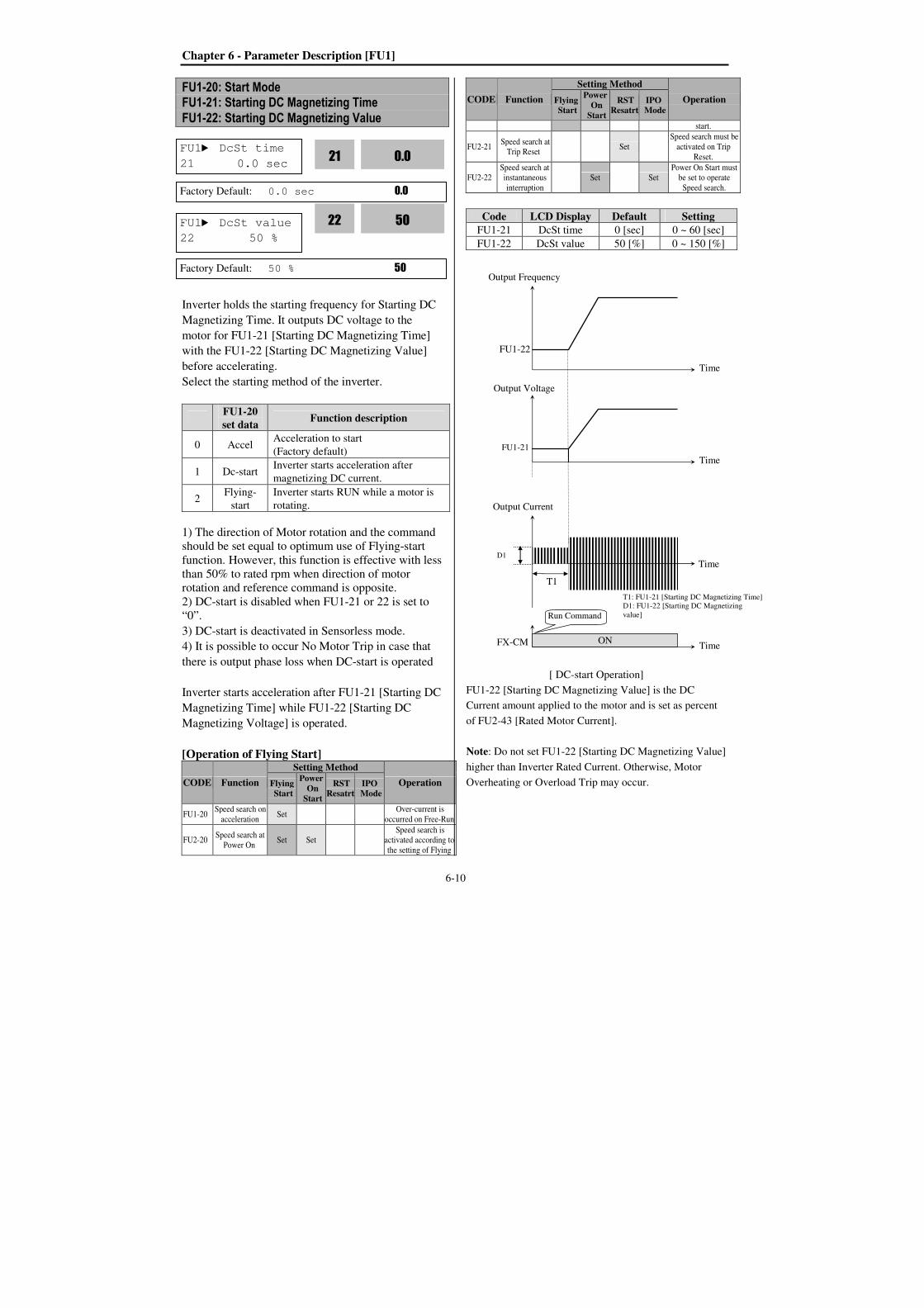
Chapter 6 - Parameter Description [FU1]
6-10
FU1-20: Start Mode FU1-21: Starting DC Magnetizing Time
FU1-22: Starting DC Magnetizing Value
Inverter holds the starting frequency for Starting DC
Magnetizing Time. It outputs DC voltage to the
motor for FU1-21 [Starting DC Magnetizing Time]
with the FU1-22 [Starting DC Magnetizing Value]
before accelerating.
Select the starting method of the inverter.
FU1-20
set data Function description
0 Accel Acceleration to start
(Factory default)
1 Dc-start Inverter starts acceleration after
magnetizing DC current.
2 Flying-
start
Inverter starts RUN while a motor is
rotating.
1) The direction of Motor rotation and the command
should be set equal to optimum use of Flying-start
function. However, this function is effective with less
than 50% to rated rpm when direction of motor
rotation and reference command is opposite.
2) DC-start is disabled when FU1-21 or 22 is set to
“0”.
3) DC-start is deactivated in Sensorless mode.
4) It is possible to occur No Motor Trip in case that
there is output phase loss when DC-start is operated
Inverter starts acceleration after FU1-21 [Starting DC
Magnetizing Time] while FU1-22 [Starting DC
Magnetizing Voltage] is operated.
[Operation of Flying Start]
CODE Function
Setting Method
Operation Flying Start
Power On
Start
RST Resatrt
IPO Mode
FU1-20 Speed search on
acceleration Set
Over-current is
occurred on Free-Run
FU2-20 Speed search at
Power On Set Set
Speed search is
activated according to
the setting of Flying
CODE Function
Setting Method
Operation Flying Start
Power On
Start
RST Resatrt
IPO Mode
start.
FU2-21 Speed search at
Trip Reset Set
Speed search must be
activated on Trip
Reset.
FU2-22
Speed search at
instantaneous
interruption
Set Set
Power On Start must
be set to operate
Speed search.
Code LCD Display Default Setting
FU1-21 DcSt time 0 [sec] 0 ~ 60 [sec]
FU1-22 DcSt value 50 [%] 0 ~ 150 [%]
[ DC-start Operation]
FU1-22 [Starting DC Magnetizing Value] is the DC
Current amount applied to the motor and is set as percent
of FU2-43 [Rated Motor Current].
Note: Do not set FU1-22 [Starting DC Magnetizing Value]
higher than Inverter Rated Current. Otherwise, Motor
Overheating or Overload Trip may occur.
FU1 DcSt value
22 50 %
50
22
Factory Default: 50 % 50
FU1 DcSt time
21 0.0 sec 0.0
21
Factory Default: 0.0 sec 0.0
Output Frequency
Time
FX-CM ON
Output Voltage
Time
Time
Run Command
FU1-22
FU1-21
T1
T1: FU1-21 [Starting DC Magnetizing Time]
D1: FU1-22 [Starting DC Magnetizing
value]
Output Current
TimeD1
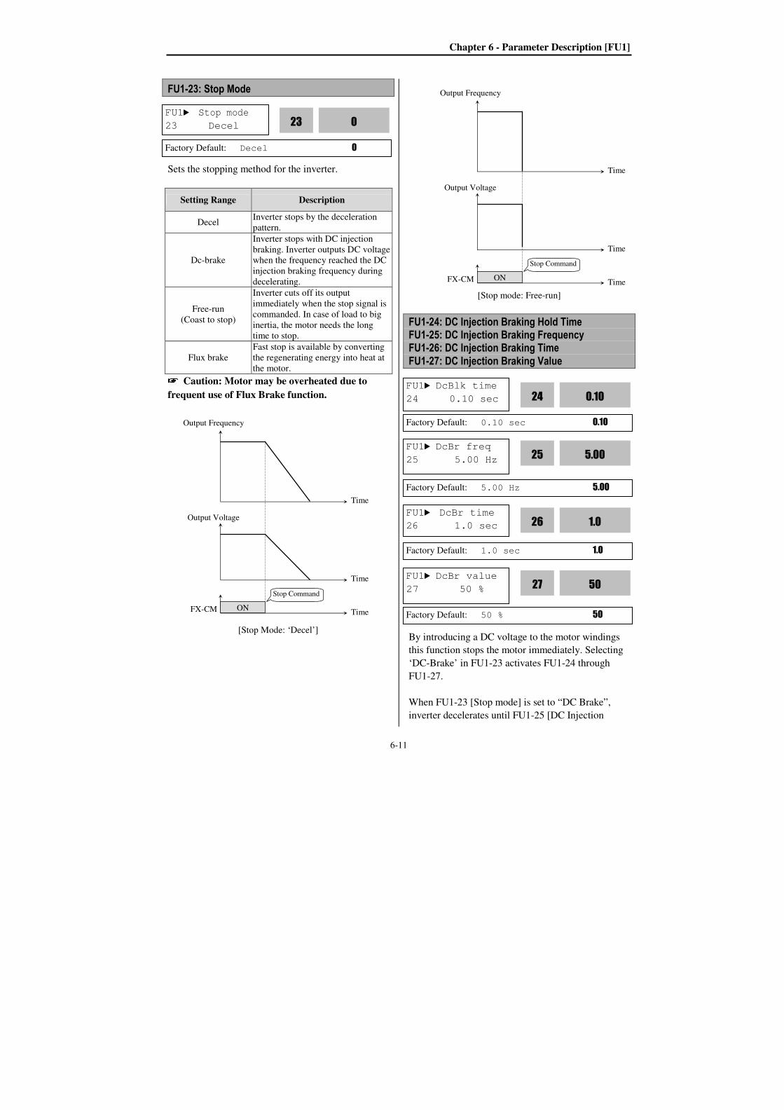
Chapter 6 - Parameter Description [FU1]
6-11
FU1-23: Stop Mode
Sets the stopping method for the inverter.
Setting Range Description
Decel Inverter stops by the deceleration
pattern.
Dc-brake
Inverter stops with DC injection
braking. Inverter outputs DC voltage
when the frequency reached the DC
injection braking frequency during
decelerating.
Free-run
(Coast to stop)
Inverter cuts off its output
immediately when the stop signal is
commanded. In case of load to big
inertia, the motor needs the long
time to stop.
Flux brake
Fast stop is available by converting
the regenerating energy into heat at
the motor. Caution: Motor may be overheated due to
frequent use of Flux Brake function.
[Stop Mode: ‘Decel’]
[Stop mode: Free-run]
FU1-24: DC Injection Braking Hold Time FU1-25: DC Injection Braking Frequency FU1-26: DC Injection Braking Time
FU1-27: DC Injection Braking Value
By introducing a DC voltage to the motor windings
this function stops the motor immediately. Selecting
‘DC-Brake’ in FU1-23 activates FU1-24 through
FU1-27.
When FU1-23 [Stop mode] is set to “DC Brake”,
inverter decelerates until FU1-25 [DC Injection
FU1 DcBr freq
25 5.00 Hz 5.00
25
Factory Default: 5.00 Hz 5.00
FU1 DcBr time
26 1.0 sec 1.0
26
Factory Default: 1.0 sec 1.0
FU1 DcBlk time
24 0.10 sec 0.10
24
Factory Default: 0.10 sec 0.10
FU1 DcBr value
27 50 % 50
27
Factory Default: 50 % 50
FU1 Stop mode
23 Decel 0
23
Factory Default: Decel 0
Output Frequency
Time
FX-CM ON
Output Voltage
Time
Time
Stop Command
Output Frequency
Time
FX-CM ON
Output Voltage
Time
Time
Stop Command
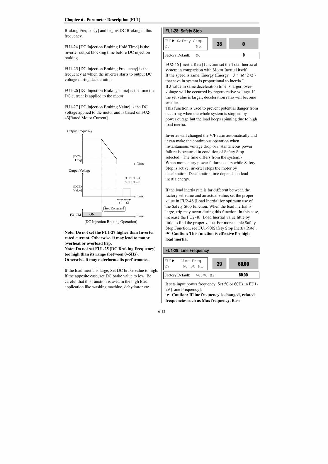
Chapter 6 - Parameter Description [FU1]
6-12
Braking Frequency] and begins DC Braking at this
frequency.
FU1-24 [DC Injection Braking Hold Time] is the
inverter output blocking time before DC injection
braking.
FU1-25 [DC Injection Braking Frequency] is the
frequency at which the inverter starts to output DC
voltage during deceleration.
FU1-26 [DC Injection Braking Time] is the time the
DC current is applied to the motor.
FU1-27 [DC Injection Braking Value] is the DC
voltage applied to the motor and is based on FU2-
43[Rated Motor Current].
[DC Injection Braking Operation]
Note: Do not set the FU1-27 higher than Inverter
rated current. Otherwise, it may lead to motor
overheat or overload trip.
Note: Do not set FU1-25 [DC Braking Frequency]
too high than its range (between 0~5Hz).
Otherwise, it may deteriorate its performance.
If the load inertia is large, Set DC brake value to high.
If the apposite case, set DC brake value to low. Be
careful that this function is used in the high load
application like washing machine, dehydrator etc..
FU1-28: Safety Stop
FU2-46 [Inertia Rate] function set the Total Inertia of
system in comparison with Motor Inertial itself.
If the speed is same, Energy (Energy = J * ω^2 /2 )
that save in system is proportional to Inertia J.
If J value in same deceleration time is larger, over-
voltage will be occurred by regernerative voltage. If
the set value is larger, deceleration ratio will become
smaller.
This function is used to prevent potential danger from
occurring when the whole system is stopped by
power outage but the load keeps spinning due to high
load inertia.
Inverter will changed the V/F ratio automatically and
it can make the continuous operation when
instantaneous voltage drop or instantaneous power
failure is occurred in condition of Safety Stop
selected. (The time differs from the system.)
When momentary power failure occurs while Safety
Stop is active, inverter stops the motor by
deceleration. Deceleration time depends on load
inertia energy.
If the load inertia rate is far different between the
factory set value and an actual value, set the proper
value in FU2-46 [Load Inertia] for optimum use of
the Safety Stop function. When the load inertial is
large, trip may occur during this function. In this case,
increase the FU2-46 [Load Inertia] value little by
little to find the proper value. For more stable Safety
Stop Function, see FU1-90[Safety Stop Inertia Rate]. Caution: This function is effective for high
load inertia.
FU1-29: Line Frequency
It sets input power frequency. Set 50 or 60Hz in FU1-
29 [Line Frequency]. Caution: If line frequency is changed, related
frequencies such as Max frequency, Base
FU1 Safety Stop
28 No 0
28
Factory Default: No 0
FU1 Line Freq
29 60.00 Hz 60.00
29
Factory Default: 60.00 Hz 60.00
Output Frequency
Time
FX-CM ON
Output Voltage
Time
Time
Stop Command
[DCBr
Freq]
[DCBr
Value]
t1 t2
t1: FU1-24
t2: FU1-26
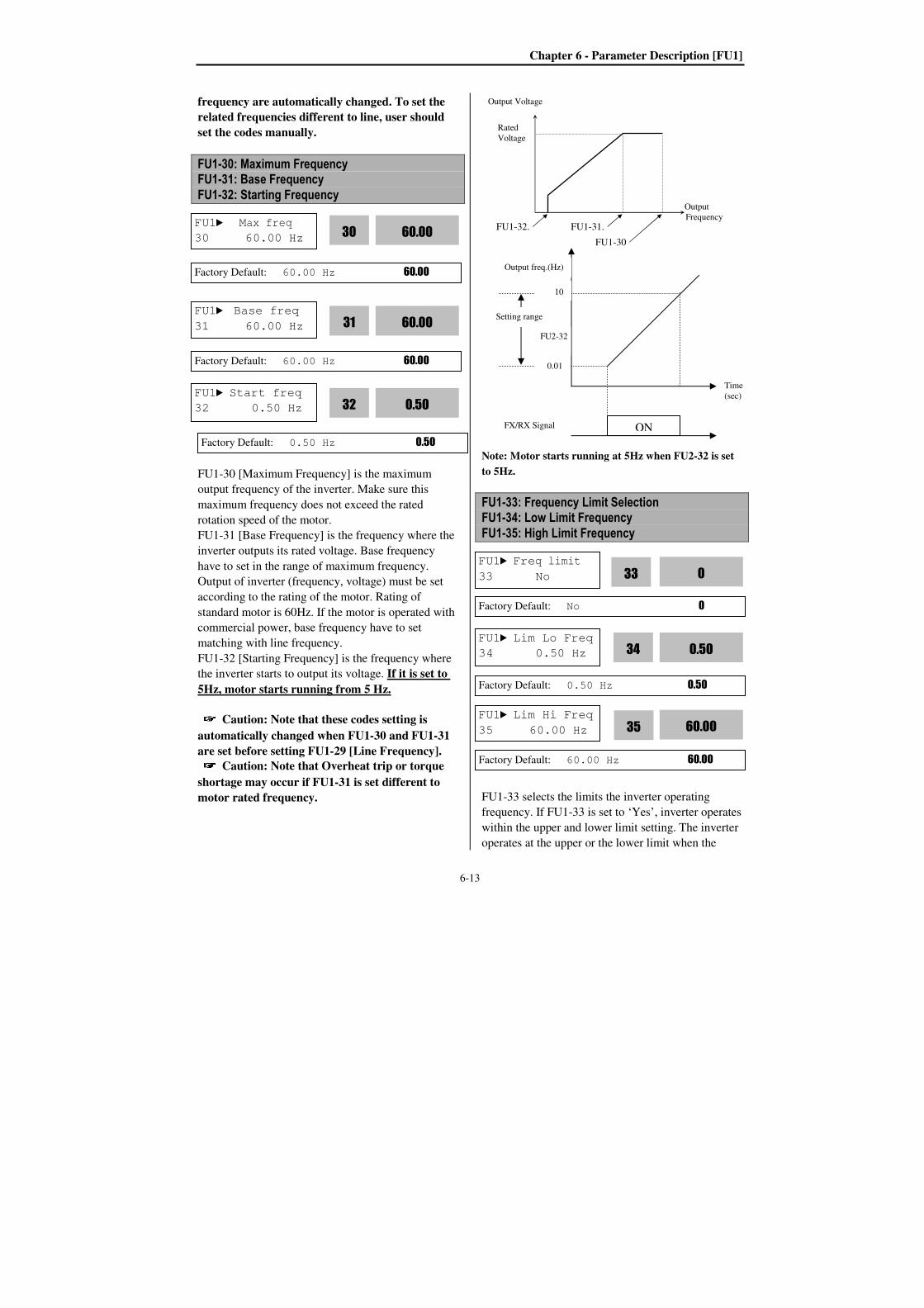
Chapter 6 - Parameter Description [FU1]
6-13
frequency are automatically changed. To set the
related frequencies different to line, user should
set the codes manually.
FU1-30: Maximum Frequency FU1-31: Base Frequency
FU1-32: Starting Frequency
FU1-30 [Maximum Frequency] is the maximum
output frequency of the inverter. Make sure this
maximum frequency does not exceed the rated
rotation speed of the motor.
FU1-31 [Base Frequency] is the frequency where the
inverter outputs its rated voltage. Base frequency
have to set in the range of maximum frequency.
Output of inverter (frequency, voltage) must be set
according to the rating of the motor. Rating of
standard motor is 60Hz. If the motor is operated with
commercial power, base frequency have to set
matching with line frequency.
FU1-32 [Starting Frequency] is the frequency where
the inverter starts to output its voltage. If it is set to
5Hz, motor starts running from 5 Hz.
Caution: Note that these codes setting is
automatically changed when FU1-30 and FU1-31
are set before setting FU1-29 [Line Frequency]. Caution: Note that Overheat trip or torque
shortage may occur if FU1-31 is set different to
motor rated frequency.
Note: Motor starts running at 5Hz when FU2-32 is set
to 5Hz.
FU1-33: Frequency Limit Selection FU1-34: Low Limit Frequency
FU1-35: High Limit Frequency
FU1-33 selects the limits the inverter operating
frequency. If FU1-33 is set to ‘Yes’, inverter operates
within the upper and lower limit setting. The inverter
operates at the upper or the lower limit when the
FU1 Max freq
30 60.00 Hz 60.00
30
Factory Default: 60.00 Hz 60.00
FU1 Base freq
31 60.00 Hz 60.00
31
Factory Default: 60.00 Hz 60.00
FU1 Start freq
32 0.50 Hz 0.50
32
Factory Default: 0.50 Hz 0.50
Output Voltage
Rated
Voltage
Output
Frequency
FU1-32. FU1-31.
FU1-30
FU1 Freq limit
33 No 0
33
Factory Default: No 0
FU1 Lim Lo Freq
34 0.50 Hz 0.50
34
Factory Default: 0.50 Hz 0.50
FU1 Lim Hi Freq
35 60.00 Hz 60.00
35
Factory Default: 60.00 Hz 60.00
ON
0.01
10
Setting range
FX/RX Signal
Output freq.(Hz)
Time
(sec)
FU2-32
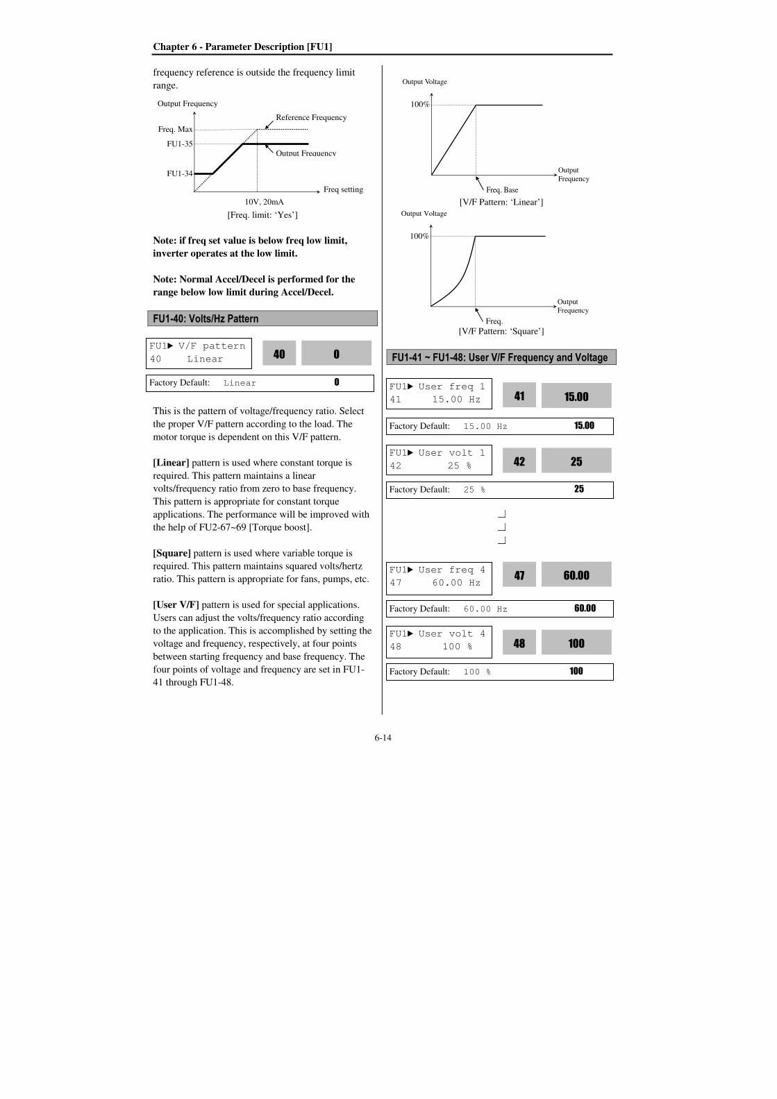
Chapter 6 - Parameter Description [FU1]
6-14
frequency reference is outside the frequency limit
range.
[Freq. limit: ‘Yes’]
Note: if freq set value is below freq low limit,
inverter operates at the low limit.
Note: Normal Accel/Decel is performed for the
range below low limit during Accel/Decel.
FU1-40: Volts/Hz Pattern
This is the pattern of voltage/frequency ratio. Select
the proper V/F pattern according to the load. The
motor torque is dependent on this V/F pattern.
[Linear] pattern is used where constant torque is
required. This pattern maintains a linear
volts/frequency ratio from zero to base frequency.
This pattern is appropriate for constant torque
applications. The performance will be improved with
the help of FU2-67~69 [Torque boost].
[Square] pattern is used where variable torque is
required. This pattern maintains squared volts/hertz
ratio. This pattern is appropriate for fans, pumps, etc.
[User V/F] pattern is used for special applications.
Users can adjust the volts/frequency ratio according
to the application. This is accomplished by setting the
voltage and frequency, respectively, at four points
between starting frequency and base frequency. The
four points of voltage and frequency are set in FU1-
41 through FU1-48.
[V/F Pattern: ‘Linear’]
[V/F Pattern: ‘Square’]
FU1-41 ~ FU1-48: User V/F Frequency and Voltage
FU1 V/F pattern
40 Linear 0
40
Factory Default: Linear 0
Output Voltage
Output
Frequency
Freq. Base
100%
Output Voltage
Output
Frequency
Freq.
Base
100%
FU1 User freq 1
41 15.00 Hz 15.00
41
Factory Default: 15.00 Hz 15.00
FU1 User volt 1
42 25 % 25
42
Factory Default: 25 % 25
FU1 User volt 4
48 100 % 100
48
Factory Default: 100 % 100
FU1 User freq 4
47 60.00 Hz 60.00
47
Factory Default: 60.00 Hz 60.00
Output Frequency
Freq. Max
Freq setting
FU1-35
FU1-34
Reference Frequency
Curve
Output Frequency
10V, 20mA
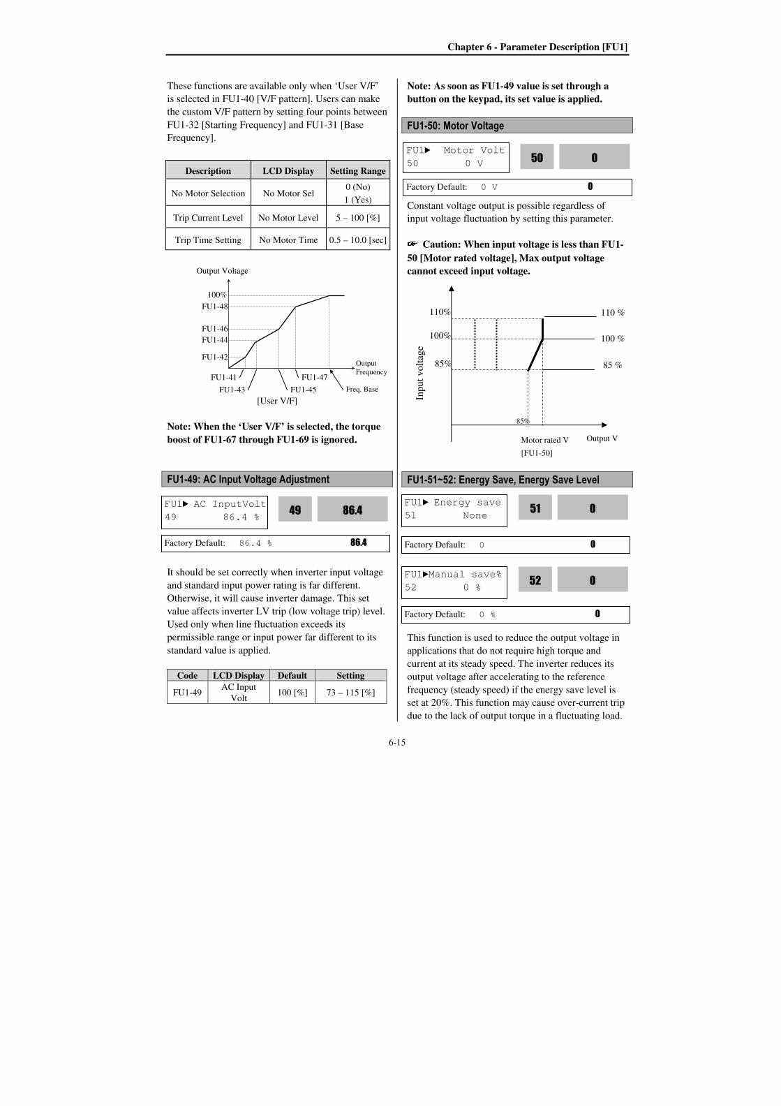
Chapter 6 - Parameter Description [FU1]
6-15
These functions are available only when ‘User V/F’
is selected in FU1-40 [V/F pattern]. Users can make
the custom V/F pattern by setting four points between
FU1-32 [Starting Frequency] and FU1-31 [Base
Frequency].
[User V/F]
Note: When the ‘User V/F’ is selected, the torque
boost of FU1-67 through FU1-69 is ignored.
FU1-49: AC Input Voltage Adjustment
It should be set correctly when inverter input voltage
and standard input power rating is far different.
Otherwise, it will cause inverter damage. This set
value affects inverter LV trip (low voltage trip) level.
Used only when line fluctuation exceeds its
permissible range or input power far different to its
standard value is applied.
Code LCD Display Default Setting
FU1-49 AC Input
Volt 100 [%] 73 – 115 [%]
Note: As soon as FU1-49 value is set through a
button on the keypad, its set value is applied.
FU1-50: Motor Voltage
Constant voltage output is possible regardless of
input voltage fluctuation by setting this parameter.
Caution: When input voltage is less than FU1-
50 [Motor rated voltage], Max output voltage
cannot exceed input voltage.
FU1-51~52: Energy Save, Energy Save Level
This function is used to reduce the output voltage in
applications that do not require high torque and
current at its steady speed. The inverter reduces its
output voltage after accelerating to the reference
frequency (steady speed) if the energy save level is
set at 20%. This function may cause over-current trip
due to the lack of output torque in a fluctuating load.
Description LCD Display Setting Range
No Motor Selection No Motor Sel 0 (No)
1 (Yes)
Trip Current Level No Motor Level 5 – 100 [%]
Trip Time Setting No Motor Time 0.5 – 10.0 [sec]
Output Voltage
Output
Frequency
Freq. Base
100%
FU1-42
FU1-41
FU1-45
FU1-44
FU1-46
FU1-48
FU1-47
FU1-43
FU1 AC InputVolt
49 86.4 % 86.4
49
Factory Default: 86.4 % 86.4
110 % 85 % 100 %
Output V
Inp
ut
vo
ltag
e
Motor rated V
[FU1-50]
100%
85%
110%
85%
FU1Manual save%
52 0 % 0
52
Factory Default: 0 % 0
FU1 Energy save
51 None 0
51
Factory Default: 0 0
FU1 Motor Volt
50 0 V 0
50
Factory Default: 0 V 0
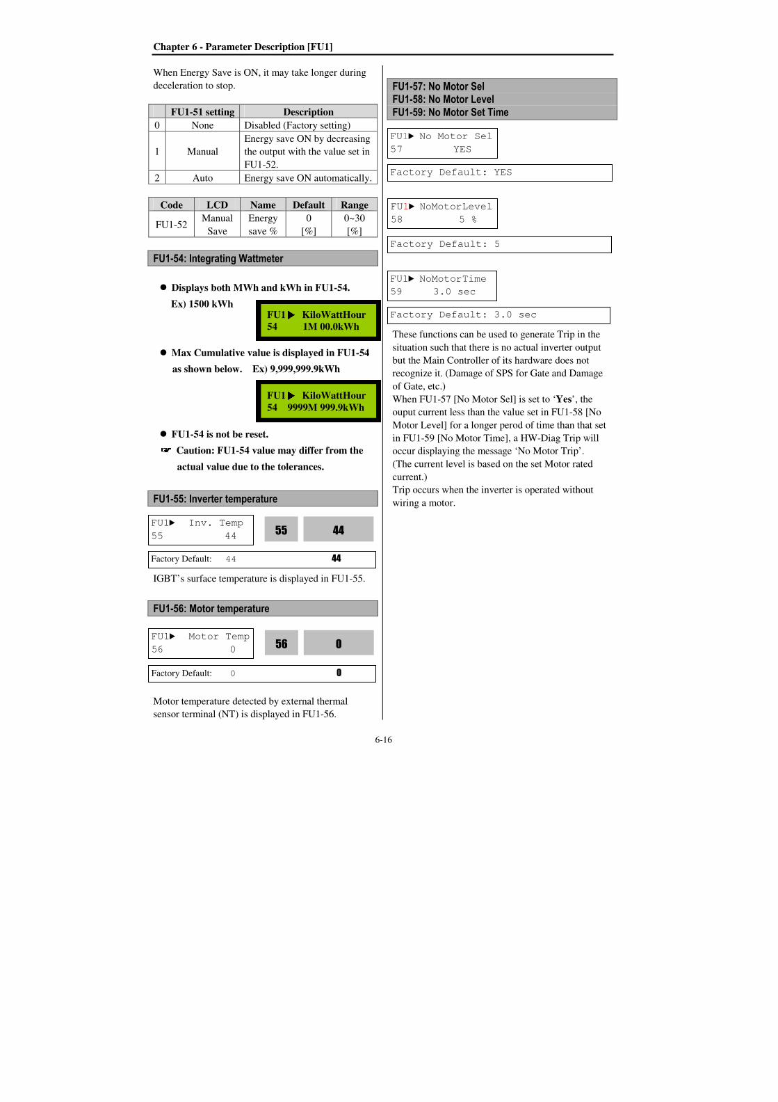
Chapter 6 - Parameter Description [FU1]
6-16
When Energy Save is ON, it may take longer during
deceleration to stop.
FU1-51 setting Description
0 None Disabled (Factory setting)
1 Manual
Energy save ON by decreasing
the output with the value set in
FU1-52.
2 Auto Energy save ON automatically.
Code LCD Name Default Range
FU1-52 Manual
Save
Energy
save %
0
[%]
0~30
[%]
FU1-54: Integrating Wattmeter
Displays both MWh and kWh in FU1-54.
Ex) 1500 kWh
Max Cumulative value is displayed in FU1-54
as shown below. Ex) 9,999,999.9kWh
FU1-54 is not be reset. Caution: FU1-54 value may differ from the
actual value due to the tolerances.
FU1-55: Inverter temperature
IGBT’s surface temperature is displayed in FU1-55.
FU1-56: Motor temperature
Motor temperature detected by external thermal
sensor terminal (NT) is displayed in FU1-56.
FU1-57: No Motor Sel FU1-58: No Motor Level FU1-59: No Motor Set Time
These functions can be used to generate Trip in the
situation such that there is no actual inverter output
but the Main Controller of its hardware does not
recognize it. (Damage of SPS for Gate and Damage
of Gate, etc.)
When FU1-57 [No Motor Sel] is set to ‘Yes’, the
ouput current less than the value set in FU1-58 [No
Motor Level] for a longer perod of time than that set
in FU1-59 [No Motor Time], a HW-Diag Trip will
occur displaying the message ‘No Motor Trip’.
(The current level is based on the set Motor rated
current.)
Trip occurs when the inverter is operated without
wiring a motor.
FU1 KiloWattHour 54 1M 00.0kWh
FU1 KiloWattHour
54 9999M 999.9kWh
FU1 Inv. Temp
55 44 44
55
Factory Default: 44 44
FU1 Motor Temp
56 0 0
56
Factory Default: 0 0
FU1 No Motor Sel
57 YES
Factory Default: YES
FU1 NoMotorLevel
58 5 %
Factory Default: 5
FU1 NoMotorTime
59 3.0 sec
Factory Default: 3.0 sec

Chapter 6 - Parameter Description [FU1]
6-17
FU1-60: Electronic Thermal (Motor i2t) Selection FU1-61: Electronic Thermal Level for 1 Minute FU1-62: Electronic Thermal Level for Continuous FU1-63: Electronic Thermal Characteristic (Motor
type) selection
These functions protect the motor from overheating
without using external thermal relay. Inverter
calculates the temperature rise in a motor based on
several parameters and determines whether or not the
motor is overheated from load current. Inverter will
disable its output and display a trip message when the
electronic thermal feature is activated.
This function activates the ETH parameters by setting
‘Yes’. ETH level is set as the percentage of FU2-43
[Motor rated current].
This is the reference current when the inverter
determines the motor has overheated. For example, it
trips in one minute when 150% of rated current of
motor set in FU2-43 flows for one minute.
Note: The set value is the percentage of FU2-43
[Rated Current of Motor].
This is the current at which the motor can run
continuously. Generally, this value is set to ‘100%’,
which means the motor rated current set in FU2-43.
This value must be set less than FU1-61 [ETH 1min].
Note: The set value is the percentage of FU2-43
[Rated Motor Current].
To make the ETH function (Motor i2t) work correctly,
the motor cooling method must be selected correctly
according to the motor.
[Self-cool] is a motor that has a cooling fan
connected directly to the shaft of the motor. Cooling
effects of a self-cooled motor decrease when a motor
is running at low speeds. The Motor is easily heated
when operating at low speed, compared to the motor
at high speed with the same current. The motor
continuous allowable current is derated as the motor
speed decreases as shown below figure.
[Forced-cool] is a motor that uses a separate motor to
power a cooling fan. As the motor speed changes, the
cooling effect does not change. FU1-62 [Electronic
thermal level for continuous] set value is utilized
regardless of operating frequency.
When operating frequency exceeds 20Hz:
Continous allowable current[%] = (0.125 *
Operating frequency + 92.5) When operating frequency not exceeds 20Hz:
Continous allowable current [%] = (1.5 * Operating
frequency + 65)
[Load Current Derating Curve]
[Motor i2t Characteristic Curve]
FU1 ETH select
60 --- Yes --- 1 60
Factory Default: Yes 1
FU1 ETH 1min
61 150 % 150 61
Factory Default: 150 % 150
FU1 ETH cont
62 120 % 120
62
Factory Default: 120 % 120
FU1 Motor type
63 Self-cool 0
63
Factory Default: Self-cool 0
100%
95%
65%
Output Current
20Hz 60Hz
Self-Cool
Forced-Cool
Load Current
Trip Time
[ETH 1 min]
1 minute
[ETH cont]
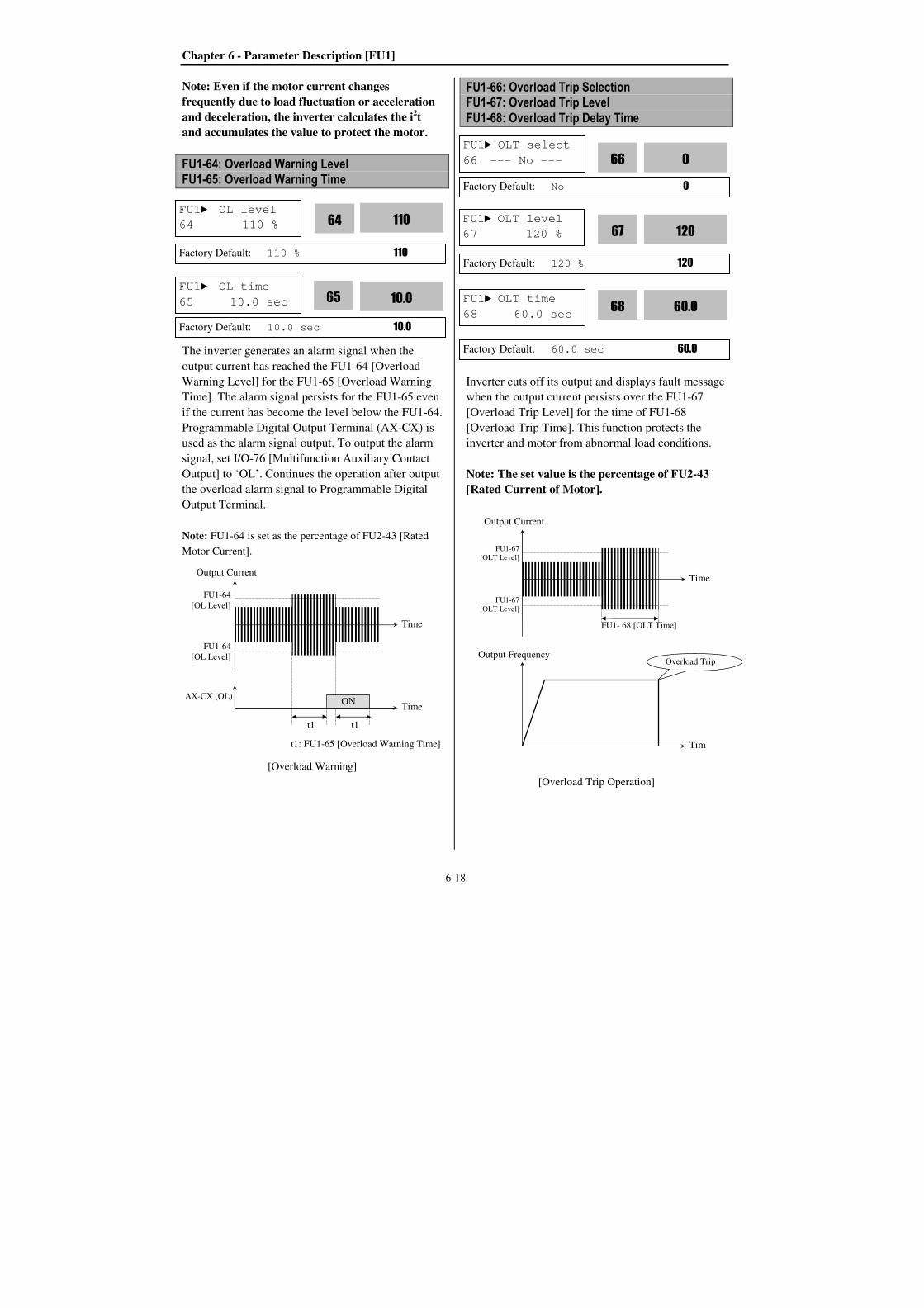
Chapter 6 - Parameter Description [FU1]
6-18
Note: Even if the motor current changes
frequently due to load fluctuation or acceleration
and deceleration, the inverter calculates the i2t
and accumulates the value to protect the motor.
FU1-64: Overload Warning Level FU1-65: Overload Warning Time
The inverter generates an alarm signal when the
output current has reached the FU1-64 [Overload
Warning Level] for the FU1-65 [Overload Warning
Time]. The alarm signal persists for the FU1-65 even
if the current has become the level below the FU1-64.
Programmable Digital Output Terminal (AX-CX) is
used as the alarm signal output. To output the alarm
signal, set I/O-76 [Multifunction Auxiliary Contact
Output] to ‘OL’. Continues the operation after output
the overload alarm signal to Programmable Digital
Output Terminal.
Note: FU1-64 is set as the percentage of FU2-43 [Rated
Motor Current].
[Overload Warning]
FU1-66: Overload Trip Selection FU1-67: Overload Trip Level
FU1-68: Overload Trip Delay Time
Inverter cuts off its output and displays fault message
when the output current persists over the FU1-67
[Overload Trip Level] for the time of FU1-68
[Overload Trip Time]. This function protects the
inverter and motor from abnormal load conditions.
Note: The set value is the percentage of FU2-43
[Rated Current of Motor].
[Overload Trip Operation]
FU1 OL level
64 110 % 110
64
Factory Default: 110 % 110
FU1 OL time
65 10.0 sec 10.0
65
Factory Default: 10.0 sec 10.0
t1: FU1-65 [Overload Warning Time]
Output Current
Time
Time
FU1-64
[OL Level]
FU1-64
[OL Level]
AX-CX (OL)ON
t1 t1
FU1 OLT select
66 --- No --- 0
66
Factory Default: No 0
FU1 OLT level
67 120 % 120
67
Factory Default: 120 % 120
FU1 OLT time
68 60.0 sec 60.0
68
Factory Default: 60.0 sec 60.0
Output Current
Time
Tim
e
FU1-67
[OLT Level]
FU1-67
[OLT Level]
Output Frequency
FU1- 68 [OLT Time]
Overload Trip
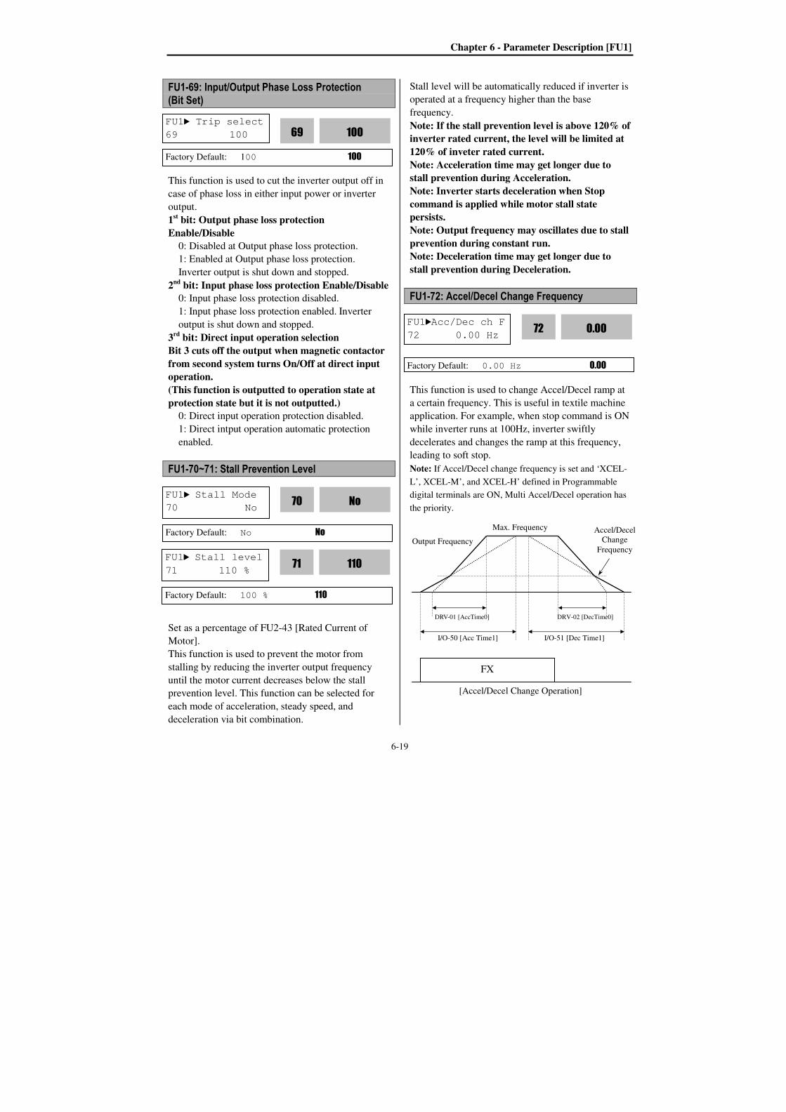
Chapter 6 - Parameter Description [FU1]
6-19
FU1-69: Input/Output Phase Loss Protection (Bit Set)
This function is used to cut the inverter output off in
case of phase loss in either input power or inverter
output.
1st bit: Output phase loss protection
Enable/Disable
0: Disabled at Output phase loss protection.
1: Enabled at Output phase loss protection.
Inverter output is shut down and stopped.
2nd bit: Input phase loss protection Enable/Disable
0: Input phase loss protection disabled.
1: Input phase loss protection enabled. Inverter
output is shut down and stopped.
3rd bit: Direct input operation selection
Bit 3 cuts off the output when magnetic contactor
from second system turns On/Off at direct input
operation.
(This function is outputted to operation state at
protection state but it is not outputted.)
0: Direct input operation protection disabled.
1: Direct intput operation automatic protection
enabled.
FU1-70~71: Stall Prevention Level
Set as a percentage of FU2-43 [Rated Current of
Motor].
This function is used to prevent the motor from
stalling by reducing the inverter output frequency
until the motor current decreases below the stall
prevention level. This function can be selected for
each mode of acceleration, steady speed, and
deceleration via bit combination.
Stall level will be automatically reduced if inverter is
operated at a frequency higher than the base
frequency.
Note: If the stall prevention level is above 120% of
inverter rated current, the level will be limited at
120% of inveter rated current.
Note: Acceleration time may get longer due to
stall prevention during Acceleration.
Note: Inverter starts deceleration when Stop
command is applied while motor stall state
persists.
Note: Output frequency may oscillates due to stall
prevention during constant run.
Note: Deceleration time may get longer due to
stall prevention during Deceleration.
FU1-72: Accel/Decel Change Frequency
This function is used to change Accel/Decel ramp at
a certain frequency. This is useful in textile machine
application. For example, when stop command is ON
while inverter runs at 100Hz, inverter swiftly
decelerates and changes the ramp at this frequency,
leading to soft stop.
Note: If Accel/Decel change frequency is set and ‘XCEL-
L’, XCEL-M’, and XCEL-H’ defined in Programmable
digital terminals are ON, Multi Accel/Decel operation has
the priority.
[Accel/Decel Change Operation]
FU1 Stall Mode
70 No No
70
Factory Default: No No
FU1 Trip select
69 100 100
69
Factory Default: 100 100
FU1Acc/Dec ch F
72 0.00 Hz 0.00
72
Factory Default: 0.00 Hz 0.00
Output Frequency
FX
Max. Frequency Accel/Decel
Change
Frequency
DRV-01 [AccTime0] DRV-02 [DecTime0]
I/O-50 [Acc Time1] I/O-51 [Dec Time1]
FU1 Stall level
71 110 % 110
71
Factory Default: 100 % 110
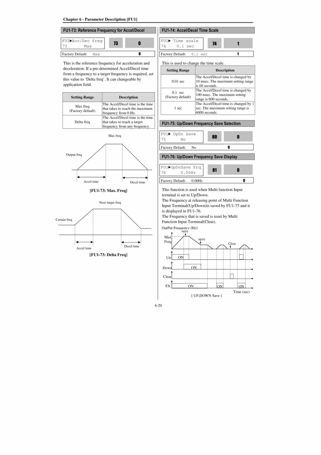
Chapter 6 - Parameter Description [FU1]
6-20
FU1-73: Reference Frequency for Accel/Decel
This is the reference frequency for acceleration and
deceleration. If a pre-determined Accel/Decel time
from a frequency to a target frequency is required, set
this value to ‘Delta freq’. It can changeable by
application field.
Setting Range Description
Max freq
(Factory defualt)
The Accel/Decel time is the time
that takes to reach the maximum
frequency from 0 Hz.
Delta freq
The Accel/Decel time is the time
that takes to reach a target
frequency from any frequency.
[FU1-73: Max. Freq]
[FU1-73: Delta Freq]
FU1-74: Accel/Decel Time Scale
This is used to change the time scale.
Setting Range Description
0.01 sec
The Accel/Decel time is changed by
10 msec. The maximum setting range
is 60 seconds.
0.1 sec
(Factory default)
The Accel/Decel time is changed by
100 msec. The maximum setting
range is 600 seconds.
1 sec
The Accel/Decel time is changed by 1
sec. The maximum setting range is
6000 seconds.
FU1-75: Up/Down Frequency Save Selection
FU1-76: Up/Down Frequency Save Display
This function is used when Multi function Input
terminal is set to Up/Down.
The Frequency at releasing point of Multi Function
Input Terminal(Up/Down)is saved by FU1-75 and it
is displayed in FU1-76.
The Frequency that is saved is reset by Multi
Function Input Terminal(Clear).
FU1Acc/Dec freq
73 Max 0
73
Factory Default: Max 0
FU1 Time scale
74 0.1 sec 1
74
Factory Default: 0.1 sec 1
Output freq
Accel time Decel time
Max freq
Certain freq
Accel time Decel time
Next target freq
FU1 UpDn Save
75 No 0
80
Factory Default: No 0
FU1UpDnSave Frq
76 0.00Hz 0
81
Factory Default: 0.00Hz 0
Max
Freq
Up
Down
Clear
OutPut Frequency [Hz]
[ UP,DOWN Save ]
ON
ON
FX
Time (sec)
ON ON ON
save
save
Clear

Chapter 6 - Parameter Description [FU2]
6-21
6.3 Function 2 Group [FU2]
FU2-00: Jump to desired code #
Set the code number to which to jump within
function group 2. Allows quick access to a desired
parameter.
FU2-01~05: Last trip 1~5 FU2-06: Erase Trips
This code displays up to five previous fault (trip)
status of the inverter. The lowest numbered fault such
as “Last trip 1” is the most recent. Use the PROG,
and key before pressing the RESET key to
check the fault content(s) such as output frequency,
output current, and the operation status whether the
inverter was accelerating, decelerating, or in constant
speed before the time of the fault occurred. Press the
ENT key to escape.
FU2-83 [Last Trip Time] is the time elapsed after last
trip occurs. User can count the last trip time from this
value.
This function erases all fault histories of FU2-01 to
FU-05 from the memory.
However, FU2-83 [Last Trip Time] cannot be reset.
FU2-07: Dwell Time FU2-08: Dwell Frequency
Accereleration after momentary stop when starts
the operation with heavy load.
Note: If the dwell time is set at ‘0’, this function is
not available.
Note: Do not set the Dwell frequency above
frequency command. Otherwise, it may lead to
operation fault.
Note: this function is disabled in Sensorless
control.
FU2-10 ~ FU2-16: Frequency Jump
FU2 Jump code
00 1
Factory Default: 1 1
FU2 Last trip-1
01 None nOn
01
Factory Default: None nOn
FU2 Last trip-5
05 None nOn
05
Factory Default: None nOn
FU2 Erase trips
06 --- No --- 0
06
Factory Default: No 0
FU2 Jump freq
10 --- No --- 0
10
Factory Default: No 0
FU2 jump lo 1
11 10.00 Hz 10.00
11
Factory Default: 10.00 Hz 10.00
FU2 Dwell freq
08 5.00 Hz 5.00
07
Factory Default: 5.00 Hz 5.00
FU2 Dwell time
07 0.0 sec 0.0
08
Factory Default: 0.0 sec 0.0
FU2-07
FU2-08
Time
RUN
Output freq.
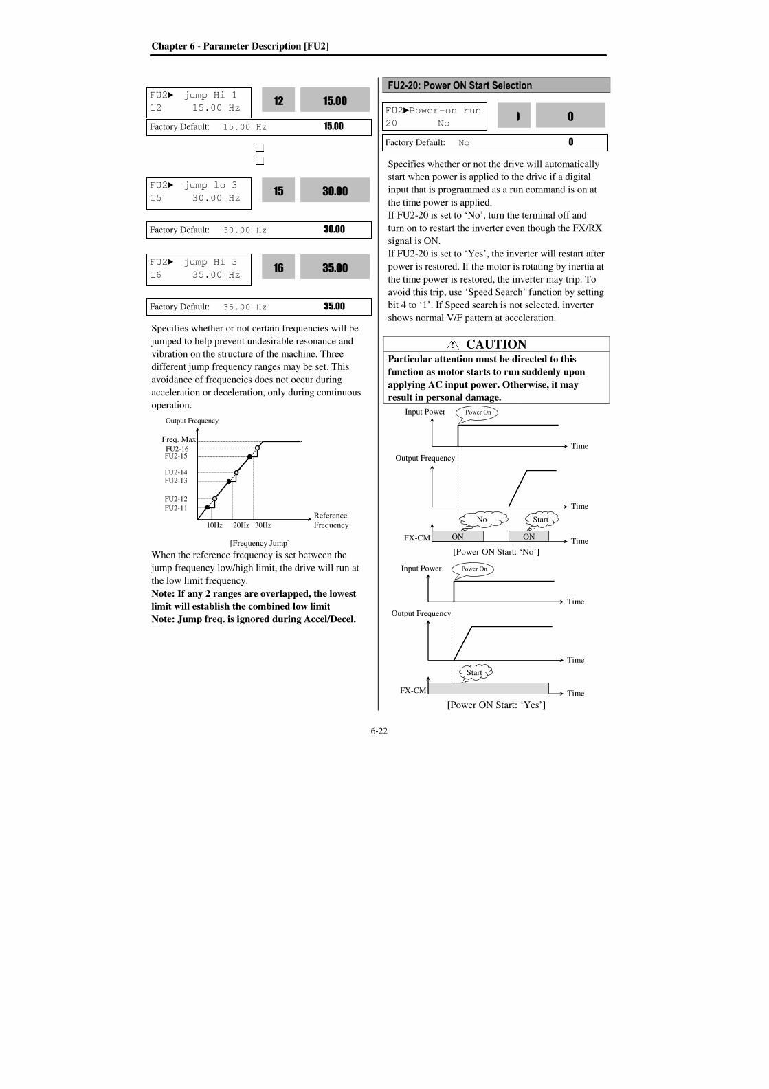
Chapter 6 - Parameter Description [FU2
Specifies whether or not certain frequencies will be
jumped to help prevent undesirable resonance and
vibration on the structure of the machine
different jump frequency ranges may be set. This
avoidance of frequencies d
acceleration or decelerati
operation.
[Frequency
When the reference frequency is set between the
jump frequency low/high limit, the drive will run at
the low limit frequency.
Note: If any 2 ranges are overlapped, the lowest
limit will establish the combined low limit
Note: Jump freq. is ignored
Output Frequency
Freq. Max
10Hz 20Hz
FU2-16 FU2-15
FU2-14FU2-13
FU2-12
FU2-11
FU2 jump Hi 1
12 15.00 Hz
Factory Default: 15.00 Hz
FU2 jump lo 3
15 30.00 Hz
Factory Default: 30.00 Hz
FU2 jump Hi 3
16 35.00 Hz
Factory Default: 35.00 Hz
Parameter Description [FU2]
6-
Specifies whether or not certain frequencies will be
jumped to help prevent undesirable resonance and
vibration on the structure of the machine. Three
different jump frequency ranges may be set. This
avoidance of frequencies does not occur during
or deceleration, only during continuous
Frequency Jump]
When the reference frequency is set between the
jump frequency low/high limit, the drive will run at
the low limit frequency.
If any 2 ranges are overlapped, the lowest
the combined low limit
Note: Jump freq. is ignored during Accel/Decel.
Reference
Frequency 20Hz 30Hz
12 15.00 Hz 15.00
12
15.00 Hz 15.00
15 30.00 Hz 30.00
15
30.00 Hz 30.00
16 35.00 Hz 35.00
16
35.00 Hz 35.00
-22
FU2-20: Power ON Start Selection
Specifies whether or not the drive will automatically
start when power is applied to the drive if a digital
input that is programmed as a run command is on at
the time power is applied.
If FU2-20 is set to ‘No’, turn the terminal off and
turn on to restart the inverter even though the FX/RX
signal is ON.
If FU2-20 is set to ‘Yes’, the inverter will restart after
power is restored. If the motor is rotating by inertia at
the time power is restored, the inverter may trip. To
avoid this trip, use ‘Speed Search
bit 4 to ‘1’. If Speed search is not selected, inverter
shows normal V/F pattern at acce
CAUTIONParticular attention must be directed to this
function as motor starts to run suddenly upon
applying AC input power. Otherwise, it may
result in personal damage.
[Power ON Start:
[Power ON Start:
FU2Power-on run
20 No 20
Factory Default: No
Input Power
FX-CM ON
Start
Power On
Output Frequency
Input Power
FX-CM ON
No
Power On
Output Frequency
20: Power ON Start Selection
Specifies whether or not the drive will automatically
start when power is applied to the drive if a digital
is programmed as a run command is on at
, turn the terminal off and
turn on to restart the inverter even though the FX/RX
inverter will restart after
s restored. If the motor is rotating by inertia at
the time power is restored, the inverter may trip. To
Speed Search’ function by setting
. If Speed search is not selected, inverter
shows normal V/F pattern at acceleration.
CAUTION Particular attention must be directed to this
function as motor starts to run suddenly upon
Otherwise, it may
[Power ON Start: ‘No’]
[Power ON Start: ‘Yes’]
0
20
0
Time
Time
Time
Time
Time ON
Start
Time
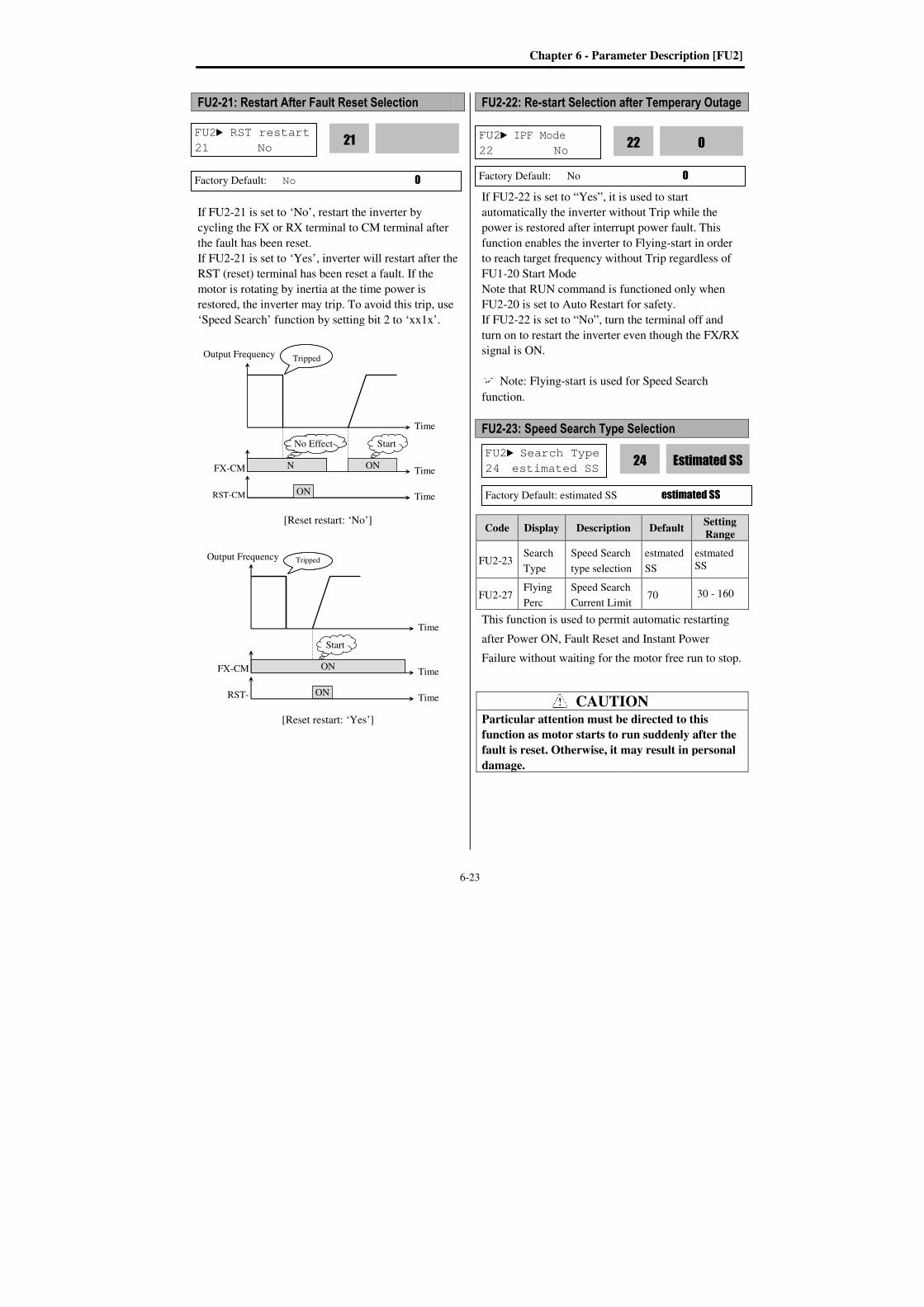
FU2-21: Restart After Fault Reset
If FU2-21 is set to
cycling the FX or RX terminal to CM terminal after
the fault has been reset.
If FU2-21 is set to
RST (reset) terminal has
motor is rotating by inertia at the time power is
restored, the inverter may trip. To avoid this trip, use
‘Speed Search’ function by setting bit 2 to
[Reset restart:
[Reset restart:
FU2 RST restart
21 No
Factory Default: No
Output Frequency
FX-CM ON
RST-CM
Output Frequency
FX-CM
RST-
21: Restart After Fault Reset Selection
21 is set to ‘No’, restart the inverter by
cycling the FX or RX terminal to CM terminal after
the fault has been reset.
21 is set to ‘Yes’, inverter will restart after the
RST (reset) terminal has been reset a fault. If the
motor is rotating by inertia at the time power is
restored, the inverter may trip. To avoid this trip, use
function by setting bit 2 to ‘xx1x’.
[Reset restart: ‘No’]
[Reset restart: ‘Yes’]
RST restart 0
21
No 0
Time
ON Time
ON Time
ON
No Effect Start
Tripped
Time
ON Time
ON Time
Start
Tripped
Chapter 6 - Parameter Description [FU2]
6-23
the
restored, the inverter may trip. To avoid this trip, use
FU2-22: Re-start Selection after Temperary Outage
If FU2-22 is set to “Yes”, it is used to start
automatically the inverter without Trip while the
power is restored after interrupt power fault.
function enables the inverter to Flying
to reach target frequency without Trip regardless of
FU1-20 Start Mode
Note that RUN command is functioned only when
FU2-20 is set to Auto Restart for safety.
If FU2-22 is set to “No”, turn the terminal off and
turn on to restart the inverter even though the FX/RX
signal is ON.
Note: Flying-start is used for Speed Search
function.
FU2-23: Speed Search Type Selection
Code Display Description
FU2-23 Search
Type
Speed Search
type selection
FU2-27 Flying
Perc
Speed Search
Current Limit
This function is used to permit automatic restarting
after Power ON, Fault Reset and Instant Power
Failure without waiting for the
CAUTIONParticular attention must be directed to this
function as motor starts to run suddenly after the
fault is reset. Otherwise, it may result in personal
damage.
FU2 IPF Mode
22 No
Factory Default: No
FU2 Search Type
24 estimated SS
Factory Default: estimated SS
Parameter Description [FU2]
after Temperary Outage
22 is set to “Yes”, it is used to start
automatically the inverter without Trip while the
power is restored after interrupt power fault. This
function enables the inverter to Flying-start in order
to reach target frequency without Trip regardless of
Note that RUN command is functioned only when
20 is set to Auto Restart for safety.
22 is set to “No”, turn the terminal off and
turn on to restart the inverter even though the FX/RX
is used for Speed Search
Speed Search Type Selection
Description Default Setting Range
Speed Search
type selection
estmated
SS
estmated
SS
Speed Search
Current Limit 70 30 - 160
This function is used to permit automatic restarting
after Power ON, Fault Reset and Instant Power
Failure without waiting for the motor free run to stop.
CAUTION Particular attention must be directed to this
function as motor starts to run suddenly after the
Otherwise, it may result in personal
0
22
0
Estimated SS 24
estimated SS

Chapter 6 - Parameter Description [FU2
FU2-27 [ Flying Perc]
value of Flying Perc in operation of Flying start or
Speed Search.
FU2-46[Load Inertia] must be set correctively.
If Speed Search function is needed at FU2
On Start Selection, FU2
Selection and FU2-Retry mode, FU1
Flying Start. Note: estimated SS
setting, real SS need to set the gaint setting of FU2
28 Ss_Kp and FU2-29 real Ss_Ki according to the
case. Note: Speed search current
percentage according to Motor rating current which is
set in FU2-43 [ Motor rating current]. It also freerun
when meets stop signal on the way of speed search.
FU2-24~26: Auto Restart Tries
Allows a tripped drive to automatically reset itself
after a fault thus making provisions for automatic
restart. The number of retries
FU2-25 and the delay before attempting the
reset and restart of the drive is programmed in FU2
26. Should the reset/restart attempts exceed the
number programmed in FU2
latch the fault, display an appropriate
and prohibit an automatic restart.
If the auto restart function is used with tripped drive,
FU2-24 [Retry Mode] should be set to YES.
FU2Retry number
25 0
Factory Default: 0
FU2Retry delay
26 1.0 sec
Factory Default: 1.0 sec
FU2Retry Mode
24 No
Factory Default: No
Parameter Description [FU2]
6-
] limits the output current to set
value of Flying Perc in operation of Flying start or
ia] must be set correctively.
If Speed Search function is needed at FU2-20 Power
On Start Selection, FU2-21 Restart After Fault Reset
Retry mode, FU1-20 must be set
estimated SS does not need to set gain
setting, real SS need to set the gaint setting of FU2-
29 real Ss_Ki according to the
Note: Speed search current limit level is set to
percentage according to Motor rating current which is
43 [ Motor rating current]. It also freerun
when meets stop signal on the way of speed search.
start Tries
Allows a tripped drive to automatically reset itself
thus making provisions for automatic
The number of retries is set in parameter
25 and the delay before attempting the fault
reset and restart of the drive is programmed in FU2-
Should the reset/restart attempts exceed the
number programmed in FU2-25, then the drive will
latch the fault, display an appropriate fault message
and prohibit an automatic restart.
function is used with tripped drive,
24 [Retry Mode] should be set to YES.
Retry number 0
25
0
Retry delay
1.0
26
1.0 sec 1.0
No
24
0
-24
If the trip persists after FU2-26, number of trip is
increased and Auto restart function is disabled. For
example, FU2-25 [Retry number] is 1 with FU2
[Retry delay] set to 10 sec, if trip persists over 10
seconds and then is reset (cleared), Auto restart is not
performed. Inverter may be tripped out in Motor
Free-run status when this function is issued. To avoid
it, use the speed search function. Set FU2
‘xx1x’. See FU2-21 ~ FU2-23. If
function is not selected, drive will be operated with
normal V/F pattern.
Note: Disabled when a low voltage (LV) trip, inverter
disable (BX) or Arm short occurs.
Note: Inverter decreases the retry number by one as a
fault occurs. If trip does not occur after restarting for
30 seconds, the inverter increases the retry number by
one and maximum number is limited by the value set
in FU2-25.
CAUTIONParticular attention must be directed to this
function as motor restarts automatically after the
fault is reset. Otherwise, it may result in personal
damage.
Output Frequency
1st Fault 2nd Fault
Restart with
Speed Search
Restart with
Speed Search
t t
26, number of trip is
increased and Auto restart function is disabled. For
25 [Retry number] is 1 with FU2-26
o 10 sec, if trip persists over 10
seconds and then is reset (cleared), Auto restart is not
performed. Inverter may be tripped out in Motor
run status when this function is issued. To avoid
it, use the speed search function. Set FU2-21 to
If Speed Search
function is not selected, drive will be operated with
Disabled when a low voltage (LV) trip, inverter
occurs.
Note: Inverter decreases the retry number by one as a
occurs. If trip does not occur after restarting for
30 seconds, the inverter increases the retry number by
one and maximum number is limited by the value set
CAUTION Particular attention must be directed to this
function as motor restarts automatically after the
Otherwise, it may result in personal
Time
Restart with
Speed Search
t: FU2-26
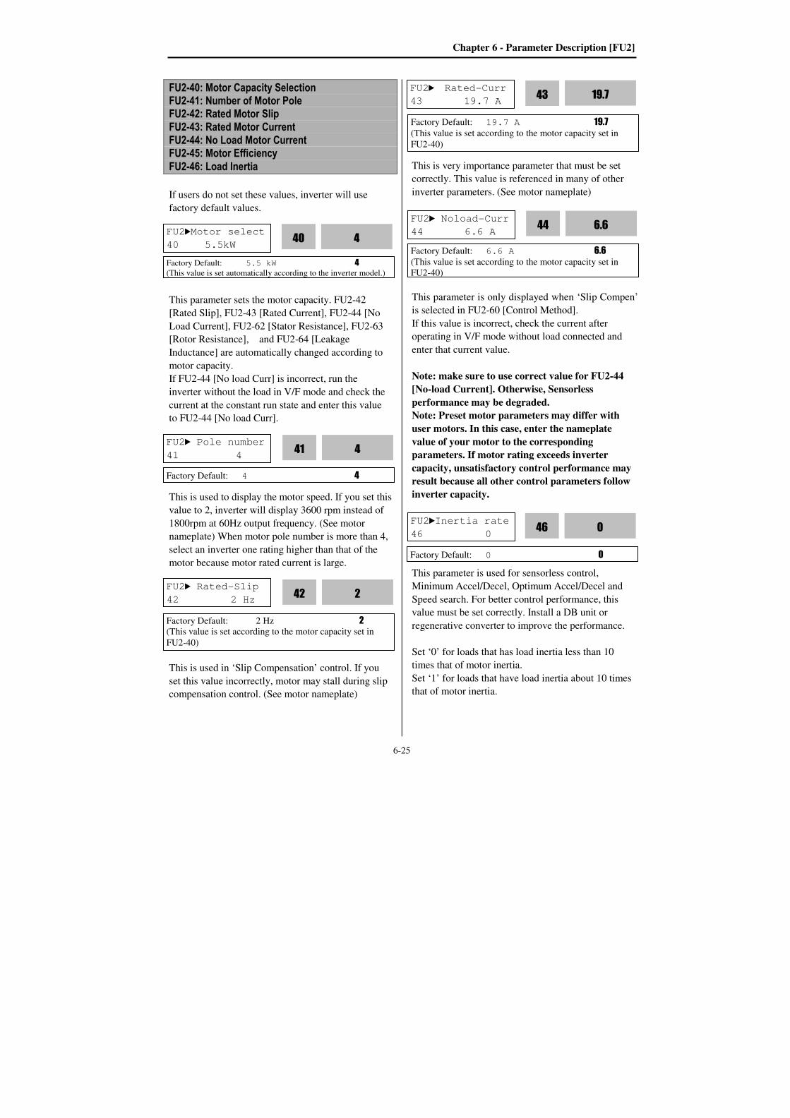
Chapter 6 - Parameter Description [FU2]
6-25
FU2-40: Motor Capacity Selection FU2-41: Number of Motor Pole FU2-42: Rated Motor Slip FU2-43: Rated Motor Current FU2-44: No Load Motor Current FU2-45: Motor Efficiency
FU2-46: Load Inertia
If users do not set these values, inverter will use
factory default values.
This parameter sets the motor capacity. FU2-42
[Rated Slip], FU2-43 [Rated Current], FU2-44 [No
Load Current], FU2-62 [Stator Resistance], FU2-63
[Rotor Resistance], and FU2-64 [Leakage
Inductance] are automatically changed according to
motor capacity.
If FU2-44 [No load Curr] is incorrect, run the
inverter without the load in V/F mode and check the
current at the constant run state and enter this value
to FU2-44 [No load Curr].
This is used to display the motor speed. If you set this
value to 2, inverter will display 3600 rpm instead of
1800rpm at 60Hz output frequency. (See motor
nameplate) When motor pole number is more than 4,
select an inverter one rating higher than that of the
motor because motor rated current is large.
This is used in ‘Slip Compensation’ control. If you
set this value incorrectly, motor may stall during slip
compensation control. (See motor nameplate)
This is very importance parameter that must be set
correctly. This value is referenced in many of other
inverter parameters. (See motor nameplate)
This parameter is only displayed when ‘Slip Compen’
is selected in FU2-60 [Control Method].
If this value is incorrect, check the current after
operating in V/F mode without load connected and
enter that current value.
Note: make sure to use correct value for FU2-44
[No-load Current]. Otherwise, Sensorless
performance may be degraded.
Note: Preset motor parameters may differ with
user motors. In this case, enter the nameplate
value of your motor to the corresponding
parameters. If motor rating exceeds inverter
capacity, unsatisfactory control performance may
result because all other control parameters follow
inverter capacity.
This parameter is used for sensorless control,
Minimum Accel/Decel, Optimum Accel/Decel and
Speed search. For better control performance, this
value must be set correctly. Install a DB unit or
regenerative converter to improve the performance.
Set ‘0’ for loads that has load inertia less than 10
times that of motor inertia.
Set ‘1’ for loads that have load inertia about 10 times
that of motor inertia.
FU2Motor select
40 5.5kW 4
40
Factory Default: 5.5 kW 4
(This value is set automatically according to the inverter model.)
FU2 Pole number
41 4
Factory Default: 4 4
FU2 Rated-Slip
42 2 Hz
Factory Default: 2 Hz 2
(This value is set according to the motor capacity set in
FU2-40)
FU2 Rated-Curr
43 19.7 A 19.7
43
Factory Default: 19.7 A 19.7
(This value is set according to the motor capacity set in
FU2-40)
FU2 Noload-Curr
44 6.6 A 6.6
44
Factory Default: 6.6 A 6.6
(This value is set according to the motor capacity set in
FU2-40)
2
42
4
41
Factory Default: 0 0
FU2Inertia rate
46 0 0
46

Chapter 6 - Parameter Description [FU2]
6-26
Motor rated slip freq [Hz]=(Rated input freq. [Hz] –
(Motor rpm * P/120))
P: Number of motor poles
(Ex) In the case of 60Hz, 4 pole, 1730 rpm motor
Motor rated slip freq [Hz]= (60[Hz]-(1750[rpm] * 4/120))
=60[Hz]-58.67[Hz]=1.33[Hz]
FU2-47: Gain for Motor Speed Display
This code is used to change the motor speed display
to rotating speed (r/min) or mechanical speed
(m/min). Speed value is displayed at DRV-09. The
display is calculated by following equation.
Rotating speed (r/min) = 120 x F / P x Motor RPM
Display Gain
Where, F=Output frequency, P= Motor pole number
FU2-48: Carrier Frequency
Code LCD
Display Factory Default Setting Range
FU2-48 Carrier
freq
0.75 ~ 2 kW 5 [kHz]
0.7 ~ 15 [kHz]
30 kW 0.7 ~ 10 [kHz]
37 ~ 75 kW 4 [kHz] 0.7 ~ 4 [kHz]
90 ~ 280 kW 3 [kHz] 0.7 ~ 3 [kHz]
315 ~ 450 kW 2 [kHz] 0.7 ~ 2 [kHz]
This parameter affects the audible sound of the motor,
noise emission from the inverter, inverter
termperature, and leakage current. If the ambient
temperature where the inverter is installed is high or
other equipment may be affected by potential inverter
noise, set this value lower. However, If it set lower
than 1KHz, it can degrade performance.
(It is recommend to use the factory defualt value.)
If set above 10kHz, reduce the rated current by 5%
per 1kHz. Setting Carrier freqeuncy set below 1.5
[kHz] when the FU2-60 [Control mode selection] is
set to Sensorless can result in reduced performance.
Caution: FU2-48 [Carrier freq] setting range
varies as inverter capacity.
FU2-49: PWM Mode Selection (to reduce noise or leakage current by changing PWM method)
Noise and leakage current can be reduced without
changing carrier freqeuncy by decreasing switching
cycle.
When Normal is selected at motor starting, inverter
changes switching frequency sequentially from low
to set value . “Low Leakage” is used to reduce
Leakage current by decreasing switching cycle.
No FU2-49 setting Description
0 Normal Operation via basic
Carrier(switching) frequency.
2 Low Leakage
Change (Carrier) switching
frequency pattern to reduce
leakage current.
Caution: Reducing the Carrier frequency may
increase noise. Caution: When [Low leakage] is selected while
carrier frequency is set lower than 2.0 kHz will be
automatically set to 2.0kHz.
FU2-52~53: Safety Stop
Set the deceleration time at FU2-52 [Dec Rate] when
Safety function is operating. Input the taking time
that the motor free run to stop in operation.
Set the Output Voltage decreasing rate at FU2-53
[Safety Perc] when Safety functin is operating.
Code LCD
Display
Factory
Defualt
Setting
Range Description
FU2-52 Dec
Rate
100
[sec]
1.0~100.0
[sec]
Safety Stop
deceleration rate
FU2-53 safety
_perc 21 2 ~ 500
Safety Stop Ouput
decreasing rate
FU2Carrier freq
48 5.0 kHz 5.0
48
Factory Default: 5.0 kHz 5.0
FU2 RPM factor
47 100 % 100
47
Factory Default: 100 % 100
FU2 PWM Select
49 Normal 0
49
Factory Default: Normal 0
FU2 Dec Rate
52 100 100
52
Factory Default: 52 100

Chapter 6 - Parameter Description [FU2]
6-27
FU2-60: Control mode selection
Selects the control mode of the inverter
FU2-60
setting LCD Display Description
0 V/F V/F Control
1 Slip compensation Slip compensation
2 Sensorless
Sensorless vector
control speed
operation
V/F control:
This parameter controls the voltage/frequency ratio
constant. It is recommended to use the torque boost
function when a greater starting torque is required.
Related function: FU2-67~69 [Torque boost].
Slip compensation:
This function is used to maintain constant motor
speed. To keep the motor speed constant, the output
frequency varies within the limit of slip frequency set
in FU2-42 according to the load current. For example,
when the motor speed decreases below the reference
speed (frequency) due to a heavy load, the inverter
increases the output frequency higher than the
reference frequency to increase the motor speed. The
inverter increases or decreases the output by delta
frequency shown below.
FU2-40~46 [Motor parameters] is automatically
determined by FU2-40 [Motor selection]. Most
suitable motor capacity corresponding inverter
capacity is set as factory setting, but the following
parameters can be adjusted if necessary.
FU2-40~46 [Motor related parameters for Slip
Compensation]
Code LCD Display Description
FU2-40 Motor select Select motor capacity
FU2-42 Rated-Slip Motor rated slip (Hz)
FU2-43 Rated-Curr Motor rated current
(rms)
FU2-44 Noload-Curr Motor no load current
(rms)
FU2-45 Efficiency Motor efficiency (%)
FU2-46 Inertia rate Motor inertia rate
Note: Incorrectly set FU2-44 [Motor No-load
Current] value may weaken the Sensorless control.
Sensorless (Sensorless vector speed control)
operation:
Use it when 1) high starting torque is needed at low
speed 2) load fluctuation is high 3) rapid response is
needed. To use this function, set FU2-40~46 [Motor
parameters] and FU2-60 [Control mode selection]
properly.
If not using LG 220V/440V Class motor: Set “Yes”
in FU2-61 [Auto tuning] first before using this
control.
Related parameters: FU2-40~46, FU2-60, FU2-
62~66
Code LCD display Parameter
FU2-62 RS Stator resistance
FU2-63 Lsigma Leakage inductance
FU2-65 SL P-gain Sensorless P gain
FU2-66 SL I-gain Sensorless I gain
[Guide for Optimal Use of Sensorless Vector
Control]
For optimal use of the sensorless control, the
following conditions should be met. If one of the
following conditions is not satisfied, the inverter may
malfunction due to insufficient torque, irregular
rotation, or excessive motor noise. In this case, it is
recommended to use V/F control.
Use a motor capacity that is equal to or one
horsepower level lower than the inverter
capacity. Two types of motor parameters can be set for
one inverter, but use only one type for sensorless
control.
FU2Control mode
60 V/F 0
60
Factory Default: V/F 0
Delta freq (Slip Comp. Freq.) = Motor Rated slip *
(Output current - Motor No load current) / (Motor rated
current - Motor No load current)
Output freq = Reference freq + Delta freq

Chapter 6 - Parameter Description [FU2]
6-28
Use a LG(HIGEN) 220V/440V(0.4kW~30kW)
class motor. If other makers’ motor or a LG
220V/380V dual rating motor is used, utilize the
auto tuning feature in FU2-61 [Auto tuning]
before starting. Set appropriate values for the electronic thermal
function, the overload limit function and the
stall prevention. The set values should exceed
100% of the rated motor current. When DRV–04 [Frequency Mode] is set to
“V1”, “V1S”, “I”, or “V1+I”, wiring should be
conducted to eliminate potential noise influence
with the frequency reference. Pole number of the motor should be 2 pole, 4
pole, or 6 pole. The distance between the inverter and the motor
should not exceed 100m (328 ft).
[Cautions on Sensorless Vector Control] Forced-cooling should be used for the motor
when the average operating speed is under 20Hz
and more than 100% load is used constantly. Motor may rotate 0.5% faster than the maximum
speed if the motor temperature does not reach
normal operating temperature. Utilize the auto-tuning feature when the motor
reaches normal temperature (average
temperature where the motor normally operates). Output torque may be reduced when an output
filter option is used between the inverter and the
motor. Overcurrent trip may occur if FU2-62 [Stator
resistance] is set twice more than auto-tuned
value.
[Detail Tuning Method for Sensorless Vector
Control] Adjust the FU2–44 [No Load Motor Current
(RMS)] value larger or smaller by 5% units if
the current is larger or smaller than that of V/F
control under small load. Adjust the FU2–42 [Rated Motor Slip] value
larger or smaller by 5% units if the speed is
faster or slower than that of V/F control with
rated load.
FU2-61~63: Auto tuning
All of the motor parameters can be tuned by setting
“YES (1)”. Auto tuning is deactivated when “No (0)”
is selected.
FU2-61
setting
LCD
Display Description
0 No Do not measure the parameter.
1 Yes Measure all parameter.
Code LCD
Display Description
Factory
Defualt
Setting
Range
FU2-62 %Rs Stator
resistance 4 [%]
0.01 – 20
[%]
FU2-63 %Lsigma Leakage
Inductance 12 [%]
0.01 –
100 [%]
The auto tuning function automatically measures the
motor parameters needed for control selected in FU2-
60 [Control mode] such as stator resistance, rotor
resistance, leakage inductance, no-load current and
Encoder feedback frequency.
The rated current, voltage, efficiency and slip
described in the motor nameplate should be entered
before performing auto tuning. If efficiency is not
indicated on the nameplate, use the preset value.
.
FU2-64: Pre-excitation Time
When the operation command (FWD, REV) is issued,
the inverter conducts pre-exciting automatically for
the time specified by this parameter.
After FU2-64 [Pre-excitation Time] elapses the
inverter starts normal operation shown in the
following graph.
Code LCD display Default Setting range
FU2-64 PreExTime 1 [sec] 0 ~ 60 [sec]
FU2 Auto tuning
61 NO 0
61
Factory Default: NO 0
FU2 PreExTime
64 1.0 sec 1.0
64
Factory Default: 1.0 sec 1.0
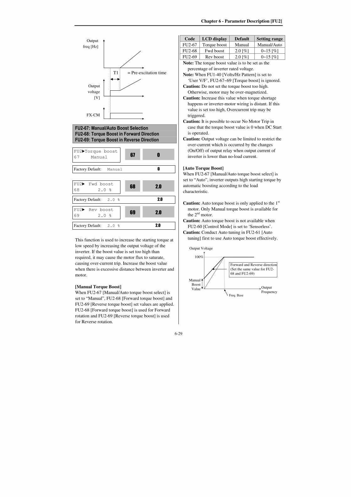
Chapter 6 - Parameter Description [FU2]
6-29
FU2-67: Manual/Auto Boost Selection FU2-68: Torque Boost in Forward Direction FU2-69: Torque Boost in Reverse Direction
This function is used to increase the starting torque at
low speed by increasing the output voltage of the
inverter. If the boost value is set too high than
required, it may cause the motor flux to saturate,
causing over-current trip. Increase the boost value
when there is excessive distance between inverter and
motor.
[Manual Torque Boost]
When FU2-67 [Manual/Auto torque boost select] is
set to “Manual”, FU2-68 [Forward torque boost] and
FU2-69 [Reverse torque boost] set values are applied.
FU2-68 [Forward torque boost] is used for Forward
rotation and FU2-69 [Reverse torque boost] is used
for Reverse rotation.
Code LCD display Default Setting range
FU2-67 Torque boost Manual Manual/Auto
FU2-68 Fwd boost 2.0 [%] 0~15 [%]
FU2-69 Rev boost 2.0 [%] 0~15 [%]
Note: The torque boost value is to be set as the
percentage of inverter rated voltage.
Note: When FU1-40 [Volts/Hz Pattern] is set to
‘User V/F’, FU2-67~69 [Torque boost] is ignored.
Caution: Do not set the torque boost too high.
Otherwise, motor may be over-magnetized.
Caution: Increase this value when torque shortage
happens or inverter-motor wiring is distant. If this
value is set too high, Overcurrent trip may be
triggered.
Caution: It is possible to occur No Motor Trip in
case that the torque boost value is 0 when DC Start
is operated.
Caution: Output voltage can be limited to restrict the
over-current which is occurred by the changes
(On/Off) of output relay when output current of
inverter is lower than no-load current.
[Auto Torque Boost]
When FU2-67 [Manual/Auto torque boost select] is
set to “Auto”, inverter outputs high starting torque by
automatic boosting according to the load
characteristic.
Caution: Auto torque boost is only applied to the 1st
motor. Only Manual torque boost is available for
the 2nd
motor.
Caution: Auto torque boost is not available when
FU2-60 [Control Mode] is set to ‘Sensorless’.
Caution: Conduct Auto tuning in FU2-61 [Auto
tuning] first to use Auto torque boost effectively.
FX-CM
Output
freq [Hz]
Output
voltage
[V]
T1 = Pre-excitation time
FU2Torque boost
67 Manual 0
67
Factory Default: Manual 0
FU2 Fwd boost
68 2.0 % 2.0
68
Factory Default: 2.0 % 2.0
FU2 Rev boost
69 2.0 % 2.0
69
Factory Default: 2.0 % 2.0
Output Voltage
Output
Frequency Freq. Base
100%
Manual
Boost
Value
Forward and Reverse direction
(Set the same value for FU2-
68 and FU2-69)
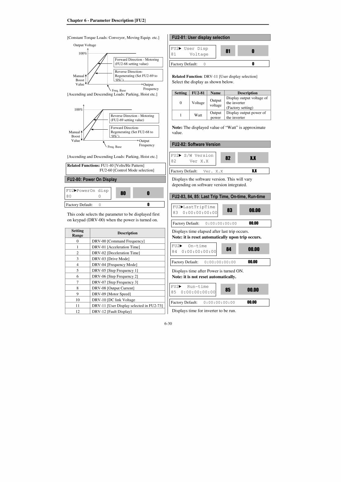
Chapter 6 - Parameter Description [FU2]
6-30
[Constant Torque Loads: Conveyor, Moving Equip. etc.]
[Ascending and Descending Loads: Parking, Hoist etc.]
[Ascending and Descending Loads: Parking, Hoist etc.]
FU2-80: Power On Display
This code selects the parameter to be displayed first
on keypad (DRV-00) when the power is turned on.
Setting Range
Description
0 DRV-00 [Command Frequency]
1 DRV-01 [Acceleration Time]
2 DRV-02 [Deceleration Time]
3 DRV-03 [Drive Mode]
4 DRV-04 [Frequency Mode]
5 DRV-05 [Step Frequency 1]
6 DRV-06 [Step Frequency 2]
7 DRV-07 [Step Frequency 3]
8 DRV-08 [Output Current]
9 DRV-09 [Motor Speed]
10 DRV-10 [DC link Voltage
11 DRV-11 [User Display selected in FU2-73]
12 DRV-12 [Fault Display]
FU2-81: User display selection
Related Function: DRV-11 [User display selection]
Select the display as shown below.
Setting FU2-81 Name Description
0 Voltage Output
voltage
Display output voltage of
the inverter
(Factory setting)
1 Watt Output
power
Display output power of
the inverter
Note: The displayed value of “Watt” is approximate
value.
FU2-82: Software Version
Displays the software version. This will vary
depending on software version integrated.
FU2-83, 84, 85: Last Trip Time, On-time, Run-time
Displays time elapsed after last trip occurs.
Note: it is reset automatically upon trip occurs.
Displays time after Power is turned ON.
Note: it is not reset automatically.
Displays time for inverter to be run.
Output Voltage
Output
Frequency Freq. Base
100%
Manual
Boost
Value
Forward Direction - Motoring
(FU2-68 setting value)
Reverse Direction-
Regenerating (Set FU2-69 to
‘0%’)
Related Functions: FU1-40 [Volts/Hz Pattern]
FU2-60 [Control Mode selection]
FU2PowerOn disp
80 0 0
80
Factory Default: 0 0
FU2 S/W Version
82 Ver X.X X.X
82
Factory Default: Ver. X.X X.X
FU2 User Disp
81 Voltage 0
81
Factory Default: 0 0
FU2LastTripTime
83 0:00:00:00:00 00.00
83
Factory Default: 0:00:00:00:00 00.00
FU2 On-time
84 0:00:00:00:00 00.00
84
Factory Default: 0:00:00:00:00 00.00
FU2 Run-time
85 0:00:00:00:00 00.00
85
Factory Default: 0:00:00:00:00 00.00
Output
Frequency Freq. Base
100%
Manual
Boost
Value
Reverse Direction - Motoring
(FU2-69 setting value)
Forward Direction-
Regenerating (Set FU2-68 to
‘0%’)

Chapter 6 - Parameter Description [FU2]
6-31
Note: it is not reset automatically.
FU2-83~85 display X : XX : XX : XX : XX
(Year:Month:Day:Hour:Minute)
FU2-87: PowerSet
Used to adjust the current inverter output power
and FU1-54 [KiloWattHour].
Setting Range: 0.1 ~ 400%
FU2-90: Parameter Display
It is used to change the parameters to be viewed.
No FU2-90 Set data
Description
0 Default Displays basic parameters.
(factory default)
1 All Para Displays all parameters.
2 Diff
Para
Displays parameters set
differently from factory setting.
FU2-91: Parameter Read FU2-92: Parameter Write
This is useful for programming multiple inverters to
have same parameter settings. The LCD keypad can
read (upload) the parameter settings from the inverter
memory and can write (download) them to other
inverters. This function is only available with LCD
keypad.
Note: When FU2-91, 92 is used, motor parameters
such as FU2-40~46, FU2-62~63 will be initialized.
Perform Auto-tuning first before using Sensorless
mode.
Note: Perform FU2-95 [Parameter save] first
before FU2-91 [Parameter Read].
1) Set FU2-91 to “Yes” and press Enter key to read
the parameters.
FU2-93: Parameter Initialize
This is used to initialize parameters back to the
factory default values. Each parameter group can be
initialized separately.
Note: Set FU2-40~46 [Motor parameters] again
after this function.
Note: Parameter initialize cannot clear trip
information. Instead, use FU2-06 [Erase trips].
Risk of Elect ric Shock
Risk of Elect ric Shock
WARNING
Risk of I njur y or Ele ctric Shock 상해나 감전 의 우려가 있습니다.주의사항을 읽고 지켜 주십시오.차단한 후 10분이상 기다려 주십시오.설치시 반드시 접지하여 주십시오.사용전에 사용설명서의 안전상감전의 우려가 있습니다.감전의 우려가 있습니다.커버를 열기전에 입력전원을경 고Risk of Elect ric Shock
Risk of Elect ric Shock
WARNINGRisk of I njur y or Ele ctric Shock 상해나 감전 의 우려가 있습니다.주의사항을 읽고 지켜 주십시오.차단한 후 10분이상 기다려 주십시오.설치시 반드시 접지하여 주십시오.사용전에 사용설명서의 안전상감전의 우려가 있습니다.감전의 우려가 있습니다.커버를 열기전에 입력전원을경 고
FU2 Para. read
91 --- No ---
Factory Default: No
FU2 Para. write
92 --- No ---
Factory Default: No
FU2 Para. read
91 --- Yes ---
2) Take the LCD
keypad out.
3) Install it to the subject
inverter and set FU2-92
to “Yes” and press Enter
to download the
parameters.
FU2 Para. write
92 --- Yes ---
FU2 Para. init
93 No 0
93
Factory Default: No 0
FU2 Para. disp
90 Default 1
90
Factory Default: Default 1
FU2 PowerSet
87 100 100 87
Factory Default: 100% 100

Chapter 6 - Parameter Description [FU2]
6-32
Setting Range Description
No Displayed after initializing is
finished. (Factory Default)
All Groups All parameter groups initialized to
factory default value.
DRV Only Drive group initialized.
FU1 Only Function 1 group initialized.
FU2 Only Function 2 group initialized.
I/O Only Input/Output group
initialized.
EXT Only External group initialized.
COM Only Communication group
initialized.
APP Only Application group
initialized.
FU2-94: Parameter Lock
This function is used to lock the parameters from
being changed. When the parameters are locked, the
display arrow changes from solid to dashed line.
The lock and unlock code is ‘12’.
FU2-95: Parameter Save (Manual Save)
When FU2-95 is set to “Yes”, the changed parameter
value is saved into memory.
FU2 Para. lock
94 0 0
94
Factory Default: 0 0
FU2 Para. save
95 No 0
95
Factory Default: 0 0
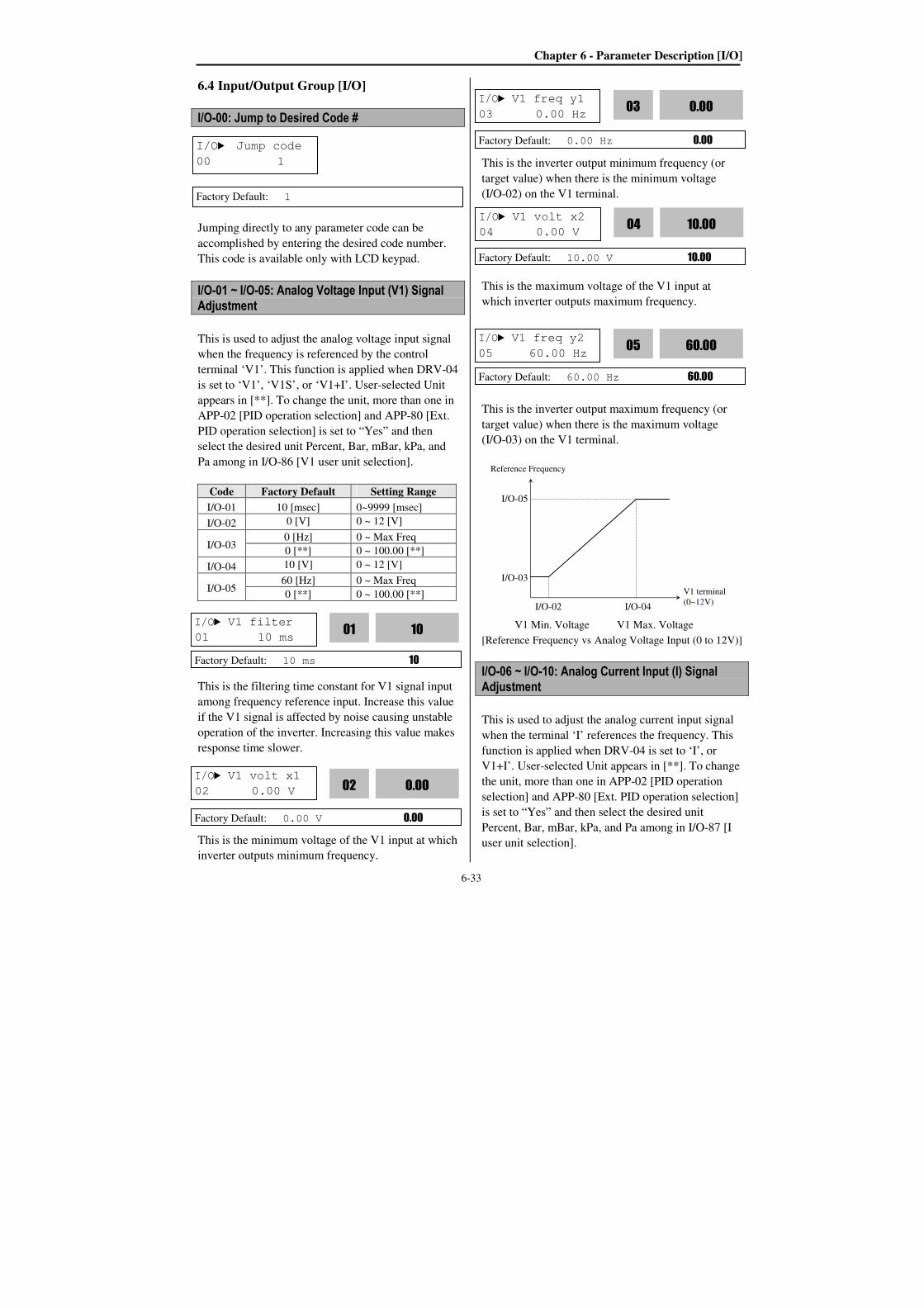
Chapter 6 - Parameter Description [I/O]
6-33
6.4 Input/Output Group [I/O]
I/O-00: Jump to Desired Code #
Jumping directly to any parameter code can be
accomplished by entering the desired code number.
This code is available only with LCD keypad.
I/O-01 ~ I/O-05: Analog Voltage Input (V1) Signal Adjustment
This is used to adjust the analog voltage input signal
when the frequency is referenced by the control
terminal ‘V1’. This function is applied when DRV-04
is set to ‘V1’, ‘V1S’, or ‘V1+I’. User-selected Unit
appears in [**]. To change the unit, more than one in
APP-02 [PID operation selection] and APP-80 [Ext.
PID operation selection] is set to “Yes” and then
select the desired unit Percent, Bar, mBar, kPa, and
Pa among in I/O-86 [V1 user unit selection].
Code Factory Default Setting Range
I/O-01 10 [msec] 0~9999 [msec]
I/O-02 0 [V] 0 ~ 12 [V]
I/O-03 0 [Hz] 0 ~ Max Freq
0 [**] 0 ~ 100.00 [**]
I/O-04 10 [V] 0 ~ 12 [V]
I/O-05 60 [Hz] 0 ~ Max Freq
0 [**] 0 ~ 100.00 [**]
This is the filtering time constant for V1 signal input
among frequency reference input. Increase this value
if the V1 signal is affected by noise causing unstable
operation of the inverter. Increasing this value makes
response time slower.
This is the minimum voltage of the V1 input at which
inverter outputs minimum frequency.
This is the inverter output minimum frequency (or
target value) when there is the minimum voltage
(I/O-02) on the V1 terminal.
This is the maximum voltage of the V1 input at
which inverter outputs maximum frequency.
This is the inverter output maximum frequency (or
target value) when there is the maximum voltage
(I/O-03) on the V1 terminal.
V1 Min. Voltage V1 Max. Voltage
[Reference Frequency vs Analog Voltage Input (0 to 12V)]
I/O-06 ~ I/O-10: Analog Current Input (I) Signal Adjustment
This is used to adjust the analog current input signal
when the terminal ‘I’ references the frequency. This
function is applied when DRV-04 is set to ‘I’, or
V1+I’. User-selected Unit appears in [**]. To change
the unit, more than one in APP-02 [PID operation
selection] and APP-80 [Ext. PID operation selection]
is set to “Yes” and then select the desired unit
Percent, Bar, mBar, kPa, and Pa among in I/O-87 [I
user unit selection].
I/O Jump code
00 1
Factory Default: 1
I/O V1 filter
01 10 ms 10
01
Factory Default: 10 ms 10
I/O V1 volt x1
02 0.00 V 0.00
02
Factory Default: 0.00 V 0.00
I/O V1 freq y1
03 0.00 Hz 0.00
03
Factory Default: 0.00 Hz 0.00
Factory Default: 10.00 V 10.00
I/O V1 freq y2
05 60.00 Hz 60.00
05
Factory Default: 60.00 Hz 60.00
Reference Frequency
I/O-05
V1 terminal
(0~12V)
I/O-03
I/O-02 I/O-04
I/O V1 volt x2
04 0.00 V 10.00
04
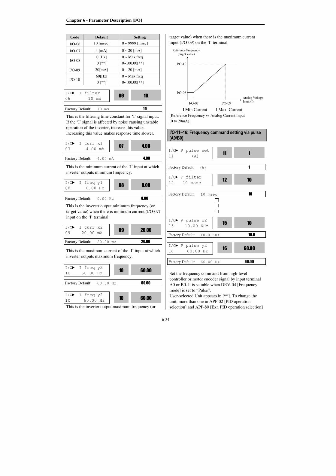
Chapter 6 - Parameter Description [I/O]
6-34
Code Default Setting
I/O-06 10 [msec] 0 ~ 9999 [msec]
I/O-07 4 [mA] 0 ~ 20 [mA]
I/O-08 0 [Hz] 0 ~ Max freq
0 [**] 0~100.00[**]
I/O-09 20[mA] 0 ~ 20 [mA]
I/O-10 60[Hz] 0 ~ Max freq
0 [**] 0~100.00[**]
This is the filtering time constant for ‘I’ signal input.
If the ‘I’ signal is affected by noise causing unstable
operation of the inverter, increase this value.
Increasing this value makes response time slower.
This is the minimum current of the ‘I’ input at which
inverter outputs minimum frequency.
This is the inverter output minimum frequency (or
target value) when there is minimum current (I/O-07)
input on the ‘I’ terminal.
This is the maximum current of the ‘I’ input at which
inverter outputs maximum frequency.
This is the inverter output maximum frequency (or
target value) when there is the maximum current
input (I/O-09) on the ‘I’ terminal.
I Min.Current I Max. Current
[Reference Frequency vs Analog Current Input
(0 to 20mA)]
I/O-11~16: Frequency command setting via pulse (A0/B0)
Set the frequency command from high-level
controller or motor encoder signal by input terminal
A0 or B0. It is settable when DRV-04 [Frequency
mode] is set to “Pulse”.
User-selected Unit appears in [**]. To change the
unit, more than one in APP-02 [PID operation
selection] and APP-80 [Ext. PID operation selection]
I/O I filter
06 10 ms 10
06
Factory Default: 10 ms 10
I/O I curr x1
07 4.00 mA 4.00
07
Factory Default: 4.00 mA 4.00
I/O I freq y1
08 0.00 Hz 0.00
08
Factory Default: 0.00 Hz 0.00
I/O I curr x2
09 20.00 mA 20.00
09
Factory Default: 20.00 mA 20.00
I/O I freq y2
10 60.00 Hz 60.00
10
Factory Default: 60.00 Hz 60.00
Reference Frequency
(target value)
I/O-10
Analog Voltage
Input (I)
I/O-08
I/O-07 I/O-09
I/O P pulse set
11 (A) 1
11
Factory Default: (A) 1
I/O P filter
12 10 msec 10
12
Factory Default: 10 msec 10
I/O P pulse x2
15 10.00 KHz 10
15
Factory Default: 10.0 KHz 10.0
I/O P pulse y2
16 60.00 Hz 60.00
16
Factory Default: 60.00 Hz 60.00
I/O I freq y2
10 60.00 Hz 60.00
10
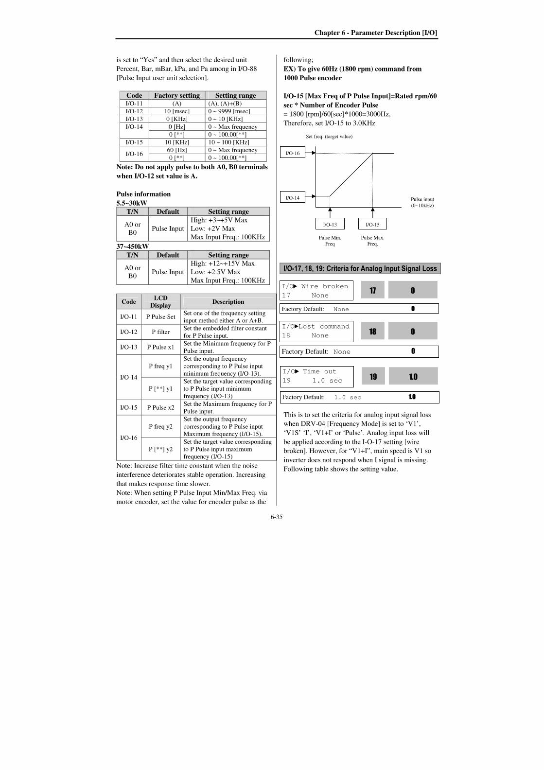
Chapter 6 - Parameter Description [I/O]
6-35
is set to “Yes” and then select the desired unit
Percent, Bar, mBar, kPa, and Pa among in I/O-88
[Pulse Input user unit selection].
Code Factory setting Setting range I/O-11 (A) (A), (A)+(B)
I/O-12 10 [msec] 0 ~ 9999 [msec]
I/O-13 0 [KHz] 0 ~ 10 [KHz]
I/O-14 0 [Hz] 0 ~ Max frequency
0 [**] 0 ~ 100.00[**]
I/O-15 10 [KHz] 10 ~ 100 [KHz]
I/O-16 60 [Hz] 0 ~ Max frequency
0 [**] 0 ~ 100.00[**]
Note: Do not apply pulse to both A0, B0 terminals
when I/O-12 set value is A.
Pulse information
5.5~30kW
T/N Default Setting range
A0 or
B0 Pulse Input
High: +3~+5V Max
Low: +2V Max
Max Input Freq.: 100KHz
37~450kW
T/N Default Setting range
A0 or
B0 Pulse Input
High: +12~+15V Max
Low: +2.5V Max
Max Input Freq.: 100KHz
Code LCD
Display Description
I/O-11 P Pulse Set Set one of the frequency setting
input method either A or A+B.
I/O-12 P filter Set the embedded filter constant
for P Pulse input.
I/O-13 P Pulse x1 Set the Minimum frequency for P
Pulse input.
I/O-14
P freq y1
Set the output frequency
corresponding to P Pulse input
minimum frequency (I/O-13).
P [**] y1
Set the target value corresponding
to P Pulse input minimum
frequency (I/O-13)
I/O-15 P Pulse x2 Set the Maximum frequency for P
Pulse input.
I/O-16
P freq y2
Set the output frequency
corresponding to P Pulse input
Maximum frequency (I/O-15).
P [**] y2
Set the target value corresponding
to P Pulse input maximum
frequency (I/O-15)
Note: Increase filter time constant when the noise
interference deteriorates stable operation. Increasing
that makes response time slower.
Note: When setting P Pulse Input Min/Max Freq. via
motor encoder, set the value for encoder pulse as the
following;
EX) To give 60Hz (1800 rpm) command from
1000 Pulse encoder
I/O-15 [Max Freq of P Pulse Input]=Rated rpm/60
sec * Number of Encoder Pulse
= 1800 [rpm]/60[sec]*1000=3000Hz,
Therefore, set I/O-15 to 3.0KHz
I/O-17, 18, 19: Criteria for Analog Input Signal Loss
This is to set the criteria for analog input signal loss
when DRV-04 [Frequency Mode] is set to ‘V1’,
‘V1S’ ‘I’, ‘V1+I’ or ‘Pulse’. Analog input loss will
be applied according to the I-O-17 setting [wire
broken]. However, for “V1+I”, main speed is V1 so
inverter does not respond when I signal is missing.
Following table shows the setting value.
I/O Wire broken
17 None 0
17
Factory Default: None 0
I/O-13 I/O-15
I/O-16
I/O-14 Pulse input
(0~10kHz)
Set freq. (target value)
Pulse Min.
Freq
Pulse Max.
Freq.
I/OLost command
18 None 0
18
Factory Default: None 0
I/O Time out
19 1.0 sec 1.0
19
Factory Default: 1.0 sec 1.0
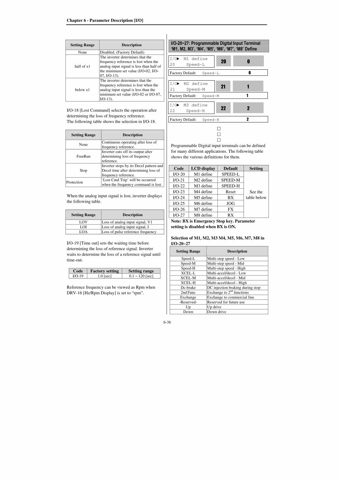
Chapter 6 - Parameter Description [I/O]
6-36
Setting Range Description
None Disabled. (Factory Default)
half of x1
The inverter determines that the
frequency reference is lost when the
analog input signal is less than half of
the minimum set value (I/O-02, I/O-
07, I/O-13).
below x1
The inverter determines that the
frequency reference is lost when the
analog input signal is less than the
minimum set value (I/O-02 or I/O-07,
I/O-13).
I/O-18 [Lost Command] selects the operation after
determining the loss of frequency reference.
The following table shows the selection in I/O-18.
Setting Range Description
None Continuous operating after loss of
frequency reference.
FreeRun
Inverter cuts off its output after
determining loss of frequency
reference.
Stop
Inverter stops by its Decel pattern and
Decel time after determining loss of
frequency reference.
Protection ‘Lost Cmd Trip’ will be occurred
when the frequency command is lost.
When the analog input signal is lost, inverter displays
the following table.
Setting Range Description
LOV Loss of analog input signal, V1
LOI Loss of analog input signal, I
LOA Loss of pulse reference frequency
I/O-19 [Time out] sets the waiting time before
determining the loss of reference signal. Inverter
waits to determine the loss of a reference signal until
time-out.
Code Factory setting Setting range I/O-19 1.0 [sec] 0.1 ~ 120 [sec]
Reference frequency can be viewed as Rpm when
DRV-16 [Hz/Rpm Display] is set to “rpm”.
I/O-20~27: Programmable Digital Input Terminal ‘M1, M2, M3’, ‘M4’, ‘M5’, ‘M6’, ‘M7’, ‘M8’ Define
Programmable Digital input terminals can be defined
for many different applications. The following table
shows the various definitions for them.
Code LCD display Default Setting
I/O-20 M1 define SPEED-L
See the
table below
I/O-21 M2 define SPEED-M
I/O-22 M3 define SPEED-H
I/O-23 M4 define Reset
I/O-24 M5 define BX
I/O-25 M6 define JOG
I/O-26 M7 define FX
I/O-27 M8 define RX
Note: BX is Emergency Stop key. Parameter
setting is disabled when BX is ON.
Selection of M1, M2, M3 M4, M5, M6, M7, M8 in
I/O-20~27
Setting Range Description
Speed-L Multi-step speed - Low
Speed-M Multi-step speed - Mid
Speed-H Multi-step speed - High
XCEL-L Multi-accel/decel - Low
XCEL-M Multi-accel/decel - Mid
XCEL-H Multi-accel/decel - High
Dc-brake DC injection braking during stop
2nd Func Exchange to 2
nd functions
Exchange Exchange to commercial line
-Reserved- Reserved for future use
Up Up drive
Down Down drive
I/O M1 define
20 Speed-L 0
20
Factory Default: Speed-L 0
I/O M2 define
21 Speed-M 1
21
Factory Default: Speed-M 1
I/O M3 define
22 Speed-H 2
22
Factory Default: Speed-H 2
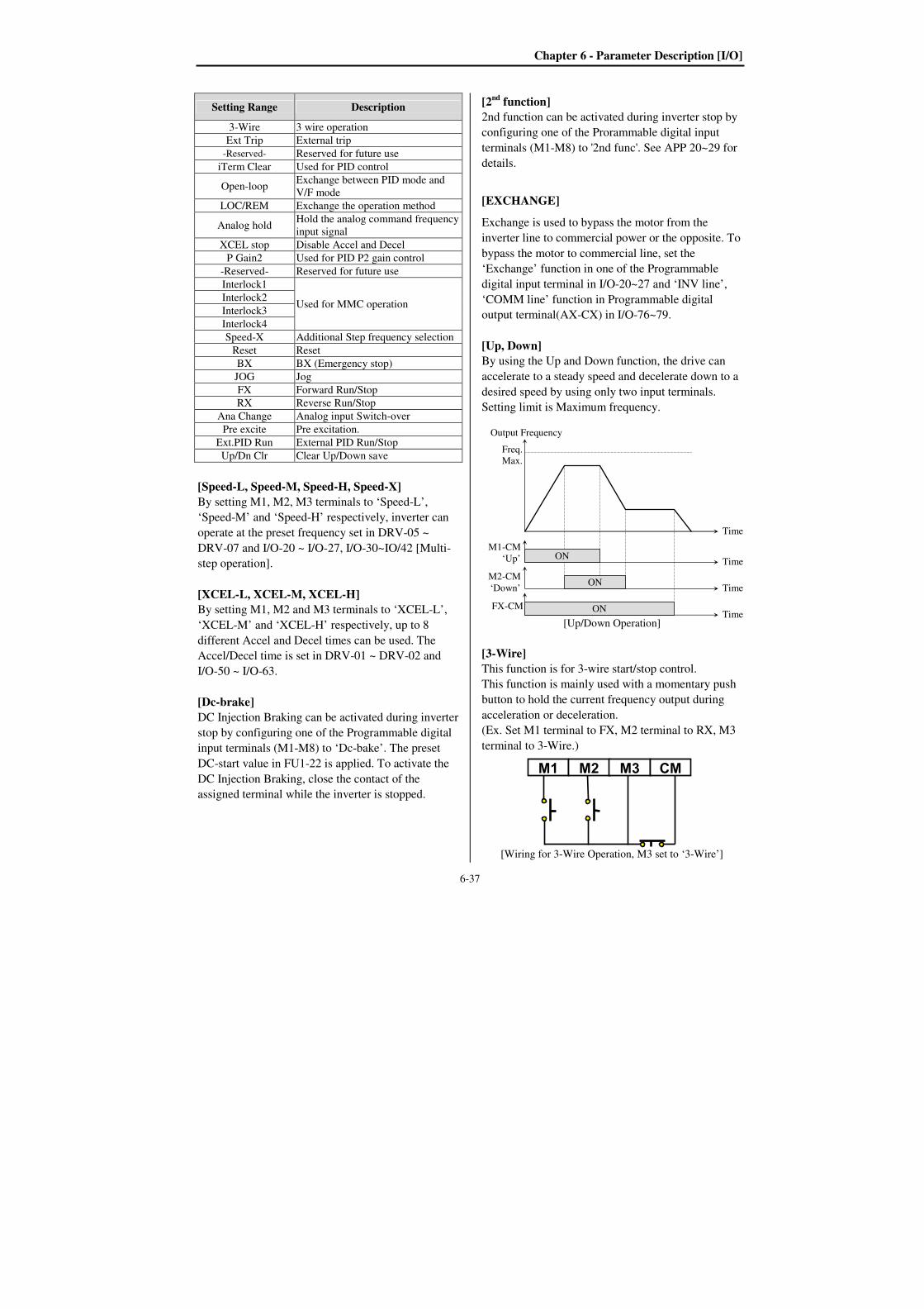
Chapter 6 - Parameter Description [I/O]
6-37
Setting Range Description
3-Wire 3 wire operation
Ext Trip External trip
-Reserved- Reserved for future use
iTerm Clear Used for PID control
Open-loop Exchange between PID mode and
V/F mode
LOC/REM Exchange the operation method
Analog hold Hold the analog command frequency
input signal
XCEL stop Disable Accel and Decel
P Gain2 Used for PID P2 gain control
-Reserved- Reserved for future use
Interlock1
Used for MMC operation Interlock2
Interlock3
Interlock4
Speed-X Additional Step frequency selection
Reset Reset
BX BX (Emergency stop)
JOG Jog
FX Forward Run/Stop
RX Reverse Run/Stop
Ana Change Analog input Switch-over
Pre excite Pre excitation.
Ext.PID Run External PID Run/Stop
Up/Dn Clr Clear Up/Down save
[Speed-L, Speed-M, Speed-H, Speed-X]
By setting M1, M2, M3 terminals to ‘Speed-L’,
‘Speed-M’ and ‘Speed-H’ respectively, inverter can
operate at the preset frequency set in DRV-05 ~
DRV-07 and I/O-20 ~ I/O-27, I/O-30~IO/42 [Multi-
step operation].
[XCEL-L, XCEL-M, XCEL-H]
By setting M1, M2 and M3 terminals to ‘XCEL-L’,
‘XCEL-M’ and ‘XCEL-H’ respectively, up to 8
different Accel and Decel times can be used. The
Accel/Decel time is set in DRV-01 ~ DRV-02 and
I/O-50 ~ I/O-63.
[Dc-brake]
DC Injection Braking can be activated during inverter
stop by configuring one of the Programmable digital
input terminals (M1-M8) to ‘Dc-bake’. The preset
DC-start value in FU1-22 is applied. To activate the
DC Injection Braking, close the contact of the
assigned terminal while the inverter is stopped.
[2nd function]
2nd function can be activated during inverter stop by
configuring one of the Prorammable digital input
terminals (M1-M8) to '2nd func'. See APP 20~29 for
details.
[EXCHANGE]
Exchange is used to bypass the motor from the
inverter line to commercial power or the opposite. To
bypass the motor to commercial line, set the
‘Exchange’ function in one of the Programmable
digital input terminal in I/O-20~27 and ‘INV line’,
‘COMM line’ function in Programmable digital
output terminal(AX-CX) in I/O-76~79.
[Up, Down]
By using the Up and Down function, the drive can
accelerate to a steady speed and decelerate down to a
desired speed by using only two input terminals.
Setting limit is Maximum frequency.
[Up/Down Operation]
[3-Wire]
This function is for 3-wire start/stop control.
This function is mainly used with a momentary push
button to hold the current frequency output during
acceleration or deceleration.
(Ex. Set M1 terminal to FX, M2 terminal to RX, M3
terminal to 3-Wire.)
[Wiring for 3-Wire Operation, M3 set to ‘3-Wire’]
M1-CM
‘Up’ ON
Output Frequency
Time
Time
M2-CM
‘Down’ON
Time
FX-CM ON Time
Freq.
Max.
M1 M2 M3 CM
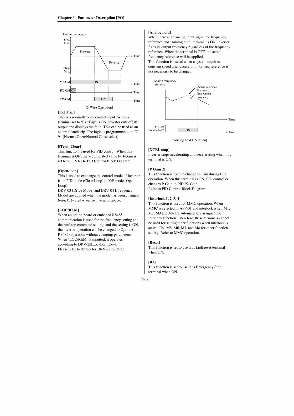
Chapter 6 - Parameter Description [I/O]
6-38
[3-Wire Operation]
[Ext Trip]
This is a normally open contact input. When a
terminal set to ‘Ext Trip’ is ON, inverter cuts off its
output and displays the fault. This can be used as an
external latch trip. The logic is programmable in I/O-
94 [Normal Open/Normal Close select].
[iTerm Clear]
This function is used for PID control. When this
terminal is ON, the accumulated value by I-Gain is
set to ‘0’. Refer to PID Control Block Diagram.
[Open-loop]
This is used to exchange the control mode of inverter
from PID mode (Close Loop) to V/F mode (Open
Loop).
DRV-03 [Drive Mode] and DRV-04 [Frequency
Mode] are applied when the mode has been changed.
Note: Only used when the inverter is stopped.
[LOC/REM]
When an option board or embeded RS485
communication is used for the frequency setting and
the run/stop command setting, and the setting is ON,
the inverter operation can be changed to Option (or
RS485) operation without changing parameters.
When ‘LOC/REM’ is inputted, it operates
according to DRV-22[LocalRemKey].
Please refer to details for DRV-22 function.
[Analog hold]
When there is an analog input signal for frequency
reference and ‘Analog hold’ terminal is ON, inverter
fixes its output frequency regardless of the frequency
reference. When the terminal is OFF, the actual
frequency reference will be applied.
This function is useful when a system requires
constant speed after acceleration or freq reference is
not necessary to be changed.
[Analog hold Operation]
[XCEL stop]
Inverter stops accelerating and decelerating when this
terminal is ON.
[P Gain 2]
This function is used to change P-Gain during PID
operation. When this terminal is ON, PID controller
changes P-Gain to PID P2-Gain.
Refer to PID Control Block Diagram.
[Interlock 1, 2, 3, 4]
This function is used for MMC operation. When
MMC is selected in APP-01 and interlock is set, M1,
M2, M3 and M4 are automatically assigned for
Interlock function. Therefore, these terminals cannot
be used for setting other functions when interlock is
active. Use M5, M6, M7, and M8 for other function
setting. Refer to MMC operation.
[Reset]
This function is set to use it as fault reset terminal
when ON.
[BX]
This function is set to use it as Emergency Stop
terminal when ON.
M3-CM ON
Output Frequency
Time
Time
FX-CM ON Time
RX-CM ON Time
Freq.
Max.
Freq.
Min.
Forward
Reverse
M1-CM
‘Analog hold’
Analog frequency
reference
Time
ON Time
Actual Reference
Frequency
Final Output
Frequency

Chapter 6 - Parameter Description [I/O]
6-39
[JOG]
This function is set to use Jog operation terminal
when ON.
[FX/RX]
This function is set to issue Forward/Reverse Run.
[Ana Change]
Inverter changes its frequency reference source from
V1 to I when ON.
Ex) In the case of V1+I operation, V1 is the
default setting and it is changed to I operation
when the terminal is turned ON.
[Pre excite]
This setting switches the inverter to pre-excition state.
This function applies the DC magnetizing current to a
motor to build the flux in Sensorless control. When
the operation command is set to ON, the state
changes from pre-excitation to normal.
A: Pre-excitating
[Ext.PID Run]
External PID controller begins operation when the
defined terminal is turned ON. This can be operated
regardless of inverter reference command or used in
conjunction with internal PID operation. Refer to
External PID operation for details
[Up/Dn Clr (Clear Up/Down save)]
This function is used for Reset (Clear) the saved
frequency when FU1-80 (Up/Dn save) is set. I/O-28: Terminal Input Status
This code displays the input status of control
terminals M1-M8, P4-P6. P4, P5, P6 will be only
displayed and used when the sub-board is installed.
[LCD Keypad Display]
Input
T/M
P6 P5 P4 M8 M7 M6 M5 M4 M3 M2 M1
10
bit
9
bit
8
bit
7
bit
6
bit
5
bit
4
bit
3
bit
2
bit
1
bit
0
bit
OFF
status 0 0 0 0 0 0 0 0 0 0 0
ON
status 1 1 1 1 1 1 1 1 1 1 1
I/O-29: Programmable Digital Input Terminal filter
time constant
Set the responsiveness of input terminals M1-M8 and
P4-P6. It is effective when noise level is high.
Increasing this will make response time slower and
decreasing faster.
Code LCD display Default Setting range
I/O-29 Ti Filt Num 15 [ms] 2~1000 [ms]
Note: Set it higher than 100msec at Inverter-
commercial line exchange operation. This will be
useful to prevent chattering and momentary
malfunction.
I/O-30: Jog Frequency
This code sets the jog frequency. See I/O-31~42,
DRV-05~ 07 for details.
I/O-31~42: Step Frequency 4, 5, 6, 7, 8, 9, 10, 11, 12, 13, 14, 15
I/O Step freq-4
31 40.00 Hz 40.00
31
Factory Default: 40.00 Hz 40.00
I/O Step freq-5
32 50.00 Hz 50.00
32
Factory Default: 50.00 Hz 50.00
I/O In status
28 00000000000 0000 28
Factory Default: 00000000000 0000
I/O Jog freq
30 10.00 Hz 10.00
30
Factory Default: 10.00 Hz 10.00
I/O Ti Filt Num
29 15 ms 15
29
Factory Default: 15 ms 15
A
Pre-Excite
FX-CM
DC magnetizing
current
Current
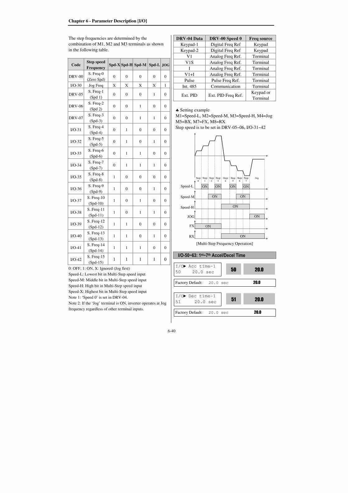
Chapter 6 - Parameter Description [I/O]
6-40
The step frequencies are determined by the
combination of M1, M2 and M3 terminals as shown
in the following table.
Code Step speed
Frequency Spd-X Spd-H Spd-M Spd-L JOG
DRV-00 S. Freq-0
(Zero Spd) 0 0 0 0 0
I/O-30 Jog Freq X X X X 1
DRV-05 S. Freq-1
(Spd 1) 0 0 0 1 0
DRV-06 S. Freq-2
(Spd 2) 0 0 1 0 0
DRV-07 S. Freq-3
(Spd-3) 0 0 1 1 0
I/O-31 S. Freq-4
(Spd-4) 0 1 0 0 0
I/O-32 S. Freq-5
(Spd-5) 0 1 0 1 0
I/O-33 S. Freq-6
(Spd-6) 0 1 1 0 0
I/O-34 S. Freq-7
(Spd-7) 0 1 1 1 0
I/O-35 S. Freq-8
(Spd-8) 1 0 0 0 0
I/O-36 S. Freq-9
(Spd-9) 1 0 0 1 0
I/O-37 S. Freq-10
(Spd-10) 1 0 1 0 0
I/O-38 S. Freq-11
(Spd-11) 1 0 1 1 0
I/O-39 S. Freq-12
(Spd-12) 1 1 0 0 0
I/O-40 S. Freq-13
(Spd-13) 1 1 0 1 0
I/O-41 S. Freq-14
(Spd-14) 1 1 1 0 0
I/O-42 S. Freq-15
(Spd-15) 1 1 1 1 0
0: OFF, 1: ON, X: Ignored (Jog first)
Speed-L: Lowest bit in Multi-Step speed input
Speed-M: Middle bit in Multi-Step speed input
Speed-H: High bit in Multi-Step speed input
Speed-X: Highest bit in Multi-Step speed input
Note 1: ‘Speed 0’ is set in DRV-04.
Note 2: If the ‘Jog’ terminal is ON, inverter operates at Jog
frequency regardless of other terminal inputs.
DRV-04 Data DRV-00 Speed 0 Freq source
Keypad-1 Digital Freq Ref Keypad
Keypad-2 Digital Freq Ref Keypad
V1 Analog Freq Ref. Terminal
V1S Analog Freq Ref. Terminal
I Analog Freq Ref. Terminal
V1+I Analog Freq Ref. Terminal
Pulse Pulse Freq Ref. Terminal
Int. 485 Communication Terminal
Ext. PID Ext. PID Freq Ref. Keypad or
Terminal
♣ Setting example
M1=Speed-L, M2=Speed-M, M3=Speed-H, M4=Jog
M5=BX, M7=FX, M8=RX
Step speed is to be set in DRV-05~06, I/O-31~42
[Multi-Step Frequency Operation]
I/O-50~63: 1st~7th Accel/Decel Time
Speed-L ON ON
Speed-M ON ON
Speed-H ON
JOG ON
FX ON
RX ON
ON ON
Step
0
Step
1
Step
2
Step
3
Step
4
Step
5
Step
6
Step
7
Jog
I/O Acc time-1
50 20.0 sec 20.0
50
Factory Default: 20.0 sec 20.0
I/O Dec time-1
51 20.0 sec 20.0
51
Factory Default: 20.0 sec 20.0

Chapter 6 - Parameter Description [I/O]
6-41
The Accel/Decel time is determined by the
combination of M1, M2 and M3 terminals as shown
in the following table.
Parameter
Code
Accel/
Decel
Time
XCEL
-H
(M3)
XCEL
-M
(M2)
XCEL
-L
(M1)
Factory
defualt
DRV-01 Accel
Time-0 0 0 0
10 sec
DRV-02 Decel
Time-0 20 sec
I/O-50 Accel
Time-1 0 0 1
20 sec
I/O-51 Decel
Time-1 20 sec
I/O-52 Accel
Time-2 0 1 0
30 sec
I/O-53 Decel
Time-2 30 sec
I/O-54 Accel
Time-3 0 1 1
40 sec
I/O-55 Decel
Time-3 40 sec
I/O-56 Accel
Time-4 1 0 0
50 sec
I/O-57 Decel
Time-4 50 sec
I/O-58 Accel
Time-5 1 0 1
40 sec
I/O-59 Decel
Time-5 40 sec
I/O-60 Accel
Time-6 1 1 0
30 sec
I/O-61 Decel
Time-6 30 sec
I/O-62 Accel
Time-7 1 1 1
20 sec
I/O-63 Decel
Time-7 20 sec
0: OFF, 1: ON
[Multi-Accel/Decel Time Operation]
I/O-70~73: S0, S1 terminal select
Analog meter displays the inverter output Frequency,
Current, Voltage, DC link voltage and External PID
output with pulse signals on the S0, S1 terminal. The
average output voltage range is 0V to 10V for S0 and
S1 terminals. I/O-71, 73 are used to adjust the S0, S1
output gain value.
M1 ON
Output Frequency
Time
Time
M2 ON Time
M3 ON Time
FX ON Time
ON ON ON
ON
Ref.
Freq.
Time
0
Time
1
Time
2
Time
3
Time
4
Time
5
Time
6
Time
7
I/O S0 mode
70 Frequency 0
70
Factory Default: Frequency 0
I/O S0 adjust
71 100 % 100
71
Factory Default: 100 % 100
I/O S1 mode
72 Voltage 0
72
Factory Default: Voltage 2
I/O S1 adjust
73 100 % 100
73
Factory Default: 100 % 100
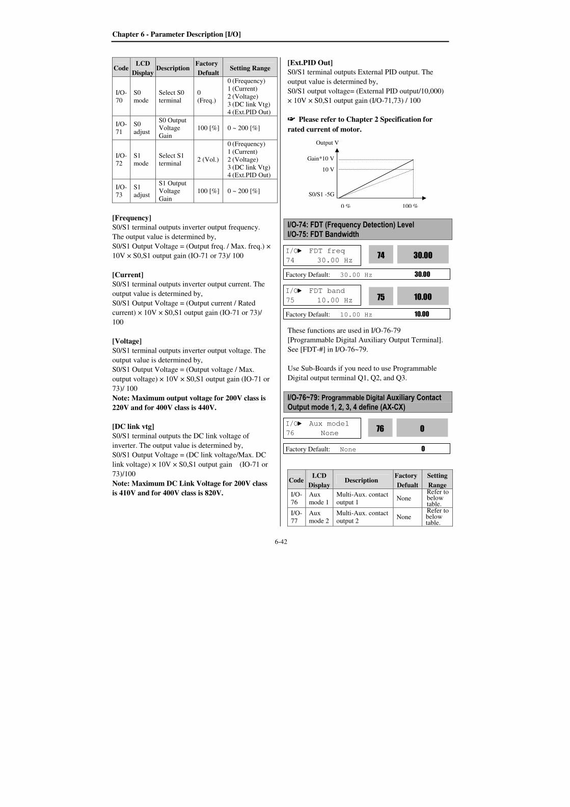
Chapter 6 - Parameter Description [I/O]
6-42
Code LCD
Display Description
Factory
Defualt Setting Range
I/O-
70
S0
mode
Select S0
terminal
0
(Freq.)
0 (Frequency)
1 (Current)
2 (Voltage)
3 (DC link Vtg)
4 (Ext.PID Out)
I/O-
71
S0
adjust
S0 Output
Voltage
Gain
100 [%] 0 ~ 200 [%]
I/O-
72
S1
mode
Select S1
terminal 2 (Vol.)
0 (Frequency)
1 (Current)
2 (Voltage)
3 (DC link Vtg)
4 (Ext.PID Out)
I/O-
73
S1
adjust
S1 Output
Voltage
Gain
100 [%] 0 ~ 200 [%]
[Frequency]
S0/S1 terminal outputs inverter output frequency.
The output value is determined by,
S0/S1 Output Voltage = (Output freq. / Max. freq.) ×
10V × S0,S1 output gain (IO-71 or 73)/ 100
[Current]
S0/S1 terminal outputs inverter output current. The
output value is determined by,
S0/S1 Output Voltage = (Output current / Rated
current) × 10V × S0,S1 output gain (IO-71 or 73)/
100
[Voltage]
S0/S1 terminal outputs inverter output voltage. The
output value is determined by,
S0/S1 Output Voltage = (Output voltage / Max.
output voltage) × 10V × S0,S1 output gain (IO-71 or
73)/ 100
Note: Maximum output voltage for 200V class is
220V and for 400V class is 440V.
[DC link vtg]
S0/S1 terminal outputs the DC link voltage of
inverter. The output value is determined by,
S0/S1 Output Voltage = (DC link voltage/Max. DC
link voltage) × 10V × S0,S1 output gain (IO-71 or
73)/100
Note: Maximum DC Link Voltage for 200V class
is 410V and for 400V class is 820V.
[Ext.PID Out]
S0/S1 terminal outputs External PID output. The
output value is determined by,
S0/S1 output voltage= (External PID output/10,000)
× 10V × S0,S1 output gain (I/O-71,73) / 100
Please refer to Chapter 2 Specification for
rated current of motor.
I/O-74: FDT (Frequency Detection) Level
I/O-75: FDT Bandwidth
These functions are used in I/O-76-79
[Programmable Digital Auxiliary Output Terminal].
See [FDT-#] in I/O-76~79.
Use Sub-Boards if you need to use Programmable
Digital output terminal Q1, Q2, and Q3.
I/O-76~79: Programmable Digital Auxiliary Contact
Output mode 1, 2, 3, 4 define (AX-CX)
Code LCD
Display Description
Factory
Defualt
Setting
Range
I/O-
76
Aux
mode 1
Multi-Aux. contact
output 1 None
Refer to below table.
I/O-
77
Aux
mode 2
Multi-Aux. contact
output 2 None
Refer to below table.
I/O FDT freq
74 30.00 Hz 30.00
74
Factory Default: 30.00 Hz 30.00
I/O FDT band
75 10.00 Hz 10.00
75
Factory Default: 10.00 Hz 10.00
I/O Aux mode1
76 None
Factory Default: None 0
0
76
S0/S1 -5G
10 V
0 % 100 %
Gain*10 V
Output V
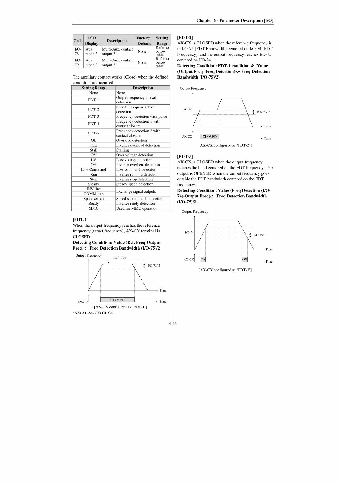
Chapter 6 - Parameter Description [I/O]
6-43
Code LCD
Display Description
Factory
Defualt
Setting
Range
I/O-
78
Aux
mode 3
Multi-Aux. contact
output 3 None
Refer to below table.
I/O-
79
Aux
mode 3
Multi-Aux. contact
output 3 None
Refer to below table.
The auxiliary contact works (Close) when the defined
condition has occurred. Setting Range Description
None None
FDT-1 Output frequency arrival
detection
FDT-2 Specific frequency level
detection
FDT-3 Frequency detection with pulse
FDT-4 Frequency detection 1 with
contact closure
FDT-5 Frequency detection 2 with
contact closure
OL Overload detection
IOL Inverter overload detection
Stall Stalling
OV Over voltage detection
LV Low voltage detection
OH Inverter overheat detection
Lost Command Lost command detection
Run Inverter running detection
Stop Inverter stop detection
Steady Steady speed detection
INV line Exchange signal outputs
COMM line
Speedsearch Speed search mode detection
Ready Inverter ready detection
MMC Used for MMC operation
[FDT-1]
When the output frequency reaches the reference
frequency (target frequency), AX-CX terminal is
CLOSED.
Detecting Condition: Value (Ref. Freq-Output
Freq)<= Freq Detection Bandwidth (I/O-75)/2
[AX-CX configured as ‘FDT-1’]
*AX: A1~A4, CX: C1~C4
[FDT-2]
AX-CX is CLOSED when the reference frequency is
in I/O-75 [FDT Bandwidth] centered on I/O-74 [FDT
Frequency], and the output frequency reaches I/O-75
centered on I/O-74.
Detecting Condition: FDT-1 condition & (Value
(Output Freq- Freq Detection)<= Freq Detection
Bandwidth (I/O-75)/2)
[AX-CX configured as ‘FDT-2’]
[FDT-3]
AX-CX is CLOSED when the output frequency
reaches the band centered on the FDT frequency. The
output is OPENED when the output frequency goes
outside the FDT bandwidth centered on the FDT
frequency.
Detecting Condition: Value (Freq Detection (I/O-
74)-Output Freq)<= Freq Detection Bandwidth
(I/O-75)/2
[AX-CX configured as ‘FDT-3’]
AX-CX CLOSED
Output Frequency
Time
Time
I/O-75 / 2 I/O-74
AX-CX ON
Output Frequency
Time
Time
I/O-75/ 2
ON
I/O-74
AX-CXCLOSED
Output Frequency
Time
Time
I/O-75/ 2
Ref. freq

Chapter 6 - Parameter Description [I/O]
6-44
[FDT-4]
AX-CX is CLOSED when the output frequency
reaches the FDT frequency. The output is OPENED
when the output frequency goes below the FDT
bandwidth centered on the FDT frequency.
Detecting Condition:
During Accel: Output freq >= Freq Detection
During Decel: Output freq > (Freq Detection (I/O-
74) - Freq Detection Bandwidth (I/O-75)/2)
[AX-CX configured as ‘FDT-4’]
[FDT-5]
This is the inverted output of [FDT-4].
Detecting Condition:
During Accel: Output freq >= Freq Detection
During Decel: Output freq > (Freq Detection (I/O-74) -
Freq Detection Bandwidth (I/O-75)/2)
[AX-CX configured as ‘FDT-5’]
[OL]
AX-CX is CLOSED when the output current has
reached the FU1-64 [Overload Warning Level] for
the FU1-65 [Overload Warning Time].
[AX-CX configured as ‘OL’]
[IOL]
AX-CX is CLOSED when the output current is above
the 110% of rated inverter current for 36 seconds. If
this situation is continued for one minute, the inverter
will cut off its output and displays ‘IOL’ (Inverter
overload) Trip. See the nameplate for the rated
inverter current. (IOL has the the inverse time
characteristic (I2t) and outputs the alarm signal when the
time is passed 60% of the designated trip time.)
[AX-CX configured as ‘IOL’]
AX-CX
Output Frequency
Time
Time
I/O-75 / 2
CLOSED
I/O-74
t1: FU1-65 [Overload Warning Time]
Output Current
Time
Time
FU1-64
[OL level]
FU1-64
[OL level]
AX-CX ON
t1 t1
Output Current
Time
Time
110% of Rated
Inverter
AX-CX ON
36sec
110% of Rated
Inverter
24sec
AX-CX ON
Output Frequency
Time
Time
I/O-75/ 2
ON
I/O-74

Chapter 6 - Parameter Description [I/O]
6-45
[Stall]
AX-CX is CLOSED when the inverter is on the stall
prevention mode.
[AX-CX configured as ‘Stall’]
[OV]
AX-CX is CLOSED when the DC link voltage is
above the Over-voltage level.
[AX-CX configured as ‘OV’]
[LV]
AX-CX is CLOSED when the DC link voltage is
below the Low-voltage level.
[AX-CX configured as ‘LV’]
[OH]
AX-CX is CLOSED when the heat sink of the
inverter is above the reference level.
[Lost Command]
AX-CX is CLOSED when frequency reference is lost.
Refer to I/0-18, I/O-92 and I/O-93.
[Run]
AX-CX is CLOSED when the inverter is running.
(Signal is not generated at DC braking.)
1) It outputs the signal from above start frequency
(FU1-32).
-. It does not output in 0Hz operation.
2) It output the signal when DC Start, DC Brake,
Pre-Heat, etc..
- It does not output in auto-tuning.
[Stop]
AX-CX is CLOSED when the inverter is stopped.
[Steady]
AX-CX is CLOSED when the inverter is running at
constant speed.
[INV line, COMM line]
This function is used in conjunction with ‘Exchange’
function of Programmable digital input for
commercial line exchange.
1) Speed search function (FU2-22) is activated
automatically during exchanging operation, enabling
smooth exchange.
2) Before the operation, the below setting is
necessary.
- Programmable intput terminal set to 'Exchange'.
- Programmable output terminal set to 'INV line'.
- Programmable output terminal set to 'COMM line'.
Note: I/O-29 [Filtering Time Constant for
Programmable Digital Input Terminals] must be set
to more than 100 [msec] to prevent chattering and
momentary malfunction during this function. Note: The function is invaild in operation.
Output Current
Time
Output Frequency
Time
FU1-71
[Stall Level]
FU1-71
[Stall Level]
Time CLOSED AX-CX
AX-CX ON
DC Link Voltage
Time
Time
LV Level (200V DC or 400V DC)
AX-CX ON
DC Link Voltage
Time
Time
OV Level (380V DC or 760V DC)
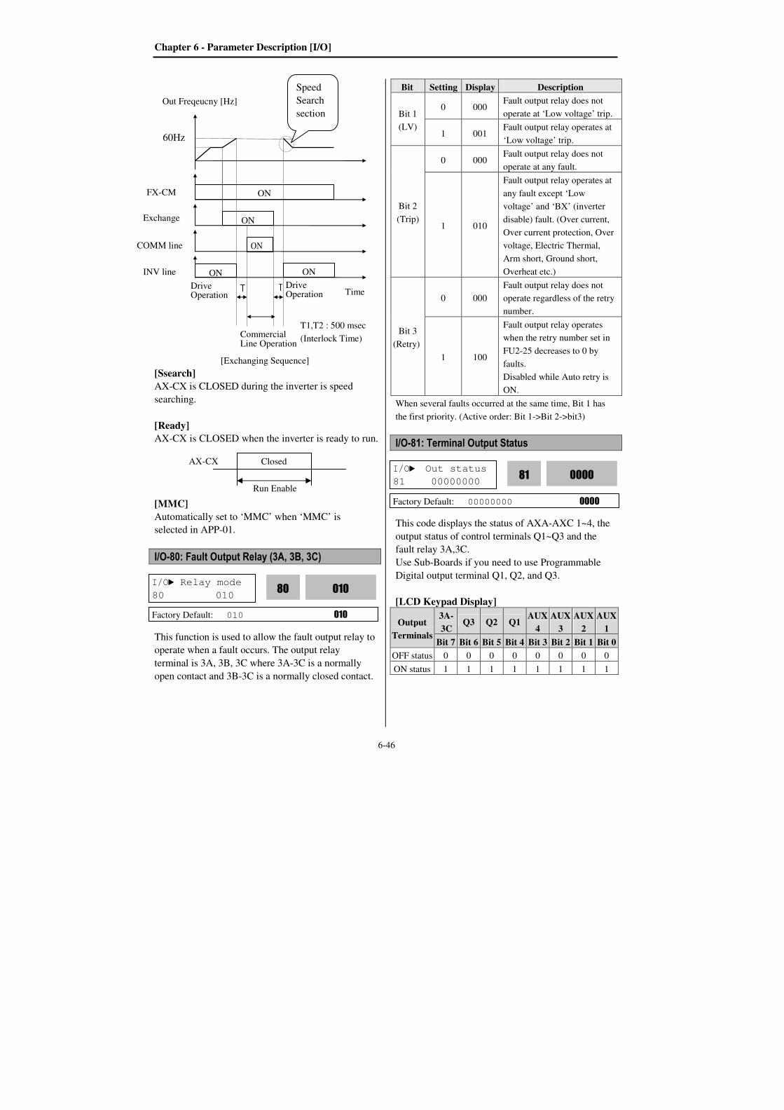
Chapter 6 - Parameter Description [I/O]
6-46
[Exchanging Sequence]
[Ssearch]
AX-CX is CLOSED during the inverter is speed
searching.
[Ready]
AX-CX is CLOSED when the inverter is ready to run.
[MMC]
Automatically set to ‘MMC’ when ‘MMC’ is
selected in APP-01.
I/O-80: Fault Output Relay (3A, 3B, 3C)
This function is used to allow the fault output relay to
operate when a fault occurs. The output relay
terminal is 3A, 3B, 3C where 3A-3C is a normally
open contact and 3B-3C is a normally closed contact.
Bit Setting Display Description
Bit 1
(LV)
0 000 Fault output relay does not
operate at ‘Low voltage’ trip.
1 001 Fault output relay operates at
‘Low voltage’ trip.
Bit 2
(Trip)
0 000 Fault output relay does not
operate at any fault.
1 010
Fault output relay operates at
any fault except ‘Low
voltage’ and ‘BX’ (inverter
disable) fault. (Over current,
Over current protection, Over
voltage, Electric Thermal,
Arm short, Ground short,
Overheat etc.)
Bit 3
(Retry)
0 000
Fault output relay does not
operate regardless of the retry
number.
1 100
Fault output relay operates
when the retry number set in
FU2-25 decreases to 0 by
faults.
Disabled while Auto retry is
ON.
When several faults occurred at the same time, Bit 1 has
the first priority. (Active order: Bit 1->Bit 2->bit3)
I/O-81: Terminal Output Status
This code displays the status of AXA-AXC 1~4, the
output status of control terminals Q1~Q3 and the
fault relay 3A,3C.
Use Sub-Boards if you need to use Programmable
Digital output terminal Q1, Q2, and Q3.
[LCD Keypad Display]
Output
Terminals
3A-
3C Q3 Q2 Q1
AUX
4
AUX
3
AUX
2
AUX
1
Bit 7 Bit 6 Bit 5 Bit 4 Bit 3 Bit 2 Bit 1 Bit 0
OFF status 0 0 0 0 0 0 0 0
ON status 1 1 1 1 1 1 1 1
I/O Out status
81 00000000 0000 81
Factory Default: 00000000 0000
I/O Relay mode
80 010 010
80
Factory Default: 010 010
Run Enable
Closed AX-CX
Commercial Line Operation
T1,T2 : 500 msec
(Interlock Time)
Drive Operation
T2 T1 INV line
COMM line
Exchange
ON
ON
ON
ON ON
Time
FX-CM
Out Freqeucny [Hz]
Speed
Search
section
60Hz
Drive Operation
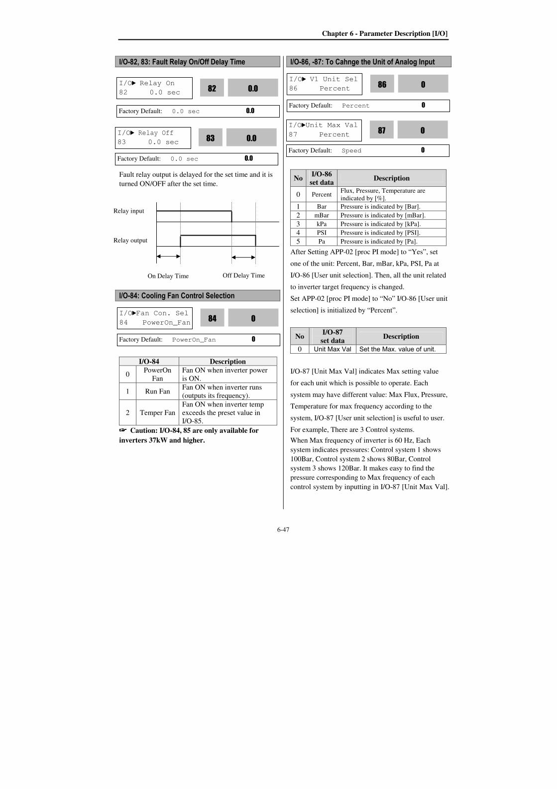
Chapter 6 - Parameter Description [I/O]
6-47
I/O-82, 83: Fault Relay On/Off Delay Time
Fault relay output is delayed for the set time and it is
turned ON/OFF after the set time.
I/O-84: Cooling Fan Control Selection
I/O-84 Description
0 PowerOn
Fan
Fan ON when inverter power
is ON.
1 Run Fan Fan ON when inverter runs
(outputs its frequency).
2 Temper Fan
Fan ON when inverter temp
exceeds the preset value in
I/O-85. Caution: I/O-84, 85 are only available for
inverters 37kW and higher.
I/O-86, -87: To Cahnge the Unit of Analog Input
No I/O-86
set data Description
0 Percent Flux, Pressure, Temperature are
indicated by [%].
1 Bar Pressure is indicated by [Bar].
2 mBar Pressure is indicated by [mBar].
3 kPa Pressure is indicated by [kPa].
4 PSI Pressure is indicated by [PSI].
5 Pa Pressure is indicated by [Pa].
After Setting APP-02 [proc PI mode] to “Yes”, set
one of the unit: Percent, Bar, mBar, kPa, PSI, Pa at
I/O-86 [User unit selection]. Then, all the unit related
to inverter target frequency is changed.
Set APP-02 [proc PI mode] to “No” I/O-86 [User unit
selection] is initialized by “Percent”.
No I/O-87
set data Description
0 Unit Max Val Set the Max. value of unit.
I/O-87 [Unit Max Val] indicates Max setting value
for each unit which is possible to operate. Each
system may have different value: Max Flux, Pressure,
Temperature for max frequency according to the
system, I/O-87 [User unit selection] is useful to user.
For example, There are 3 Control systems.
When Max frequency of inverter is 60 Hz, Each
system indicates pressures: Control system 1 shows
100Bar, Control system 2 shows 80Bar, Control
system 3 shows 120Bar. It makes easy to find the
pressure corresponding to Max frequency of each
control system by inputting in I/O-87 [Unit Max Val].
I/O Relay On
82 0.0 sec 0.0
82
Factory Default: 0.0 sec 0.0
I/O Relay Off
83 0.0 sec 0.0
83
Factory Default: 0.0 sec 0.0
I/OFan Con. Sel
84 PowerOn_Fan 0
84
Factory Default: PowerOn_Fan 0
I/O V1 Unit Sel
86 Percent 0
86
Factory Default: Percent 0
I/OUnit Max Val
87 Percent 0
87
Factory Default: Speed 0
Relay input
Relay output
On Delay Time Off Delay Time
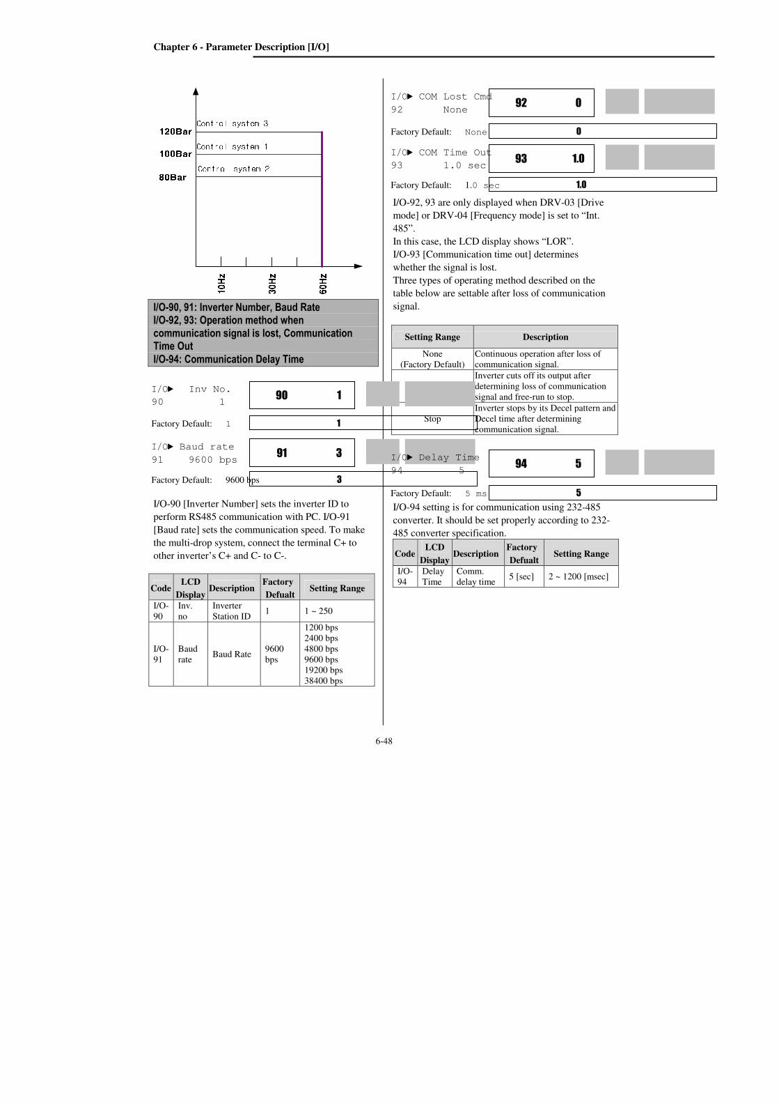
Chapter 6 - Parameter Description [I/O]
6-48
I/O-90, 91: Inverter Number, Baud Rate I/O-92, 93: Operation method when communication signal is lost, Communication Time Out
I/O-94: Communication Delay Time
I/O-90 [Inverter Number] sets the inverter ID to
perform RS485 communication with PC. I/O-91
[Baud rate] sets the communication speed. To make
the multi-drop system, connect the terminal C+ to
other inverter’s C+ and C- to C-.
I/O-92, 93 are only displayed when DRV-03 [Drive
mode] or DRV-04 [Frequency mode] is set to “Int.
485”.
In this case, the LCD display shows “LOR”.
I/O-93 [Communication time out] determines
whether the signal is lost.
Three types of operating method described on the
table below are settable after loss of communication
signal.
Setting Range Description
None
(Factory Default)
Continuous operation after loss of
communication signal.
FreeRun
Inverter cuts off its output after
determining loss of communication
signal and free-run to stop.
Stop
Inverter stops by its Decel pattern and
Decel time after determining
communication signal.
I/O-94 setting is for communication using 232-485
converter. It should be set properly according to 232-
485 converter specification.
Code LCD
Display Description
Factory
Defualt Setting Range
I/O-
94
Delay
Time
Comm.
delay time 5 [sec] 2 ~ 1200 [msec]
Code LCD
Display Description
Factory
Defualt Setting Range
I/O-
90
Inv.
no
Inverter
Station ID 1 1 ~ 250
I/O-
91
Baud
rate Baud Rate
9600
bps
1200 bps
2400 bps
4800 bps
9600 bps
19200 bps
38400 bps
I/O COM Lost Cmd
92 None 0 92
Factory Default: None 0
I/O COM Time Out
93 1.0 sec 1.0 93
Factory Default: 1.0 sec 1.0
I/O Inv No.
90 1 1 90
Factory Default: 1 1
I/O Baud rate
91 9600 bps 3 91
Factory Default: 9600 bps 3
I/O Delay Time
94 5 5 94
Factory Default: 5 ms 5
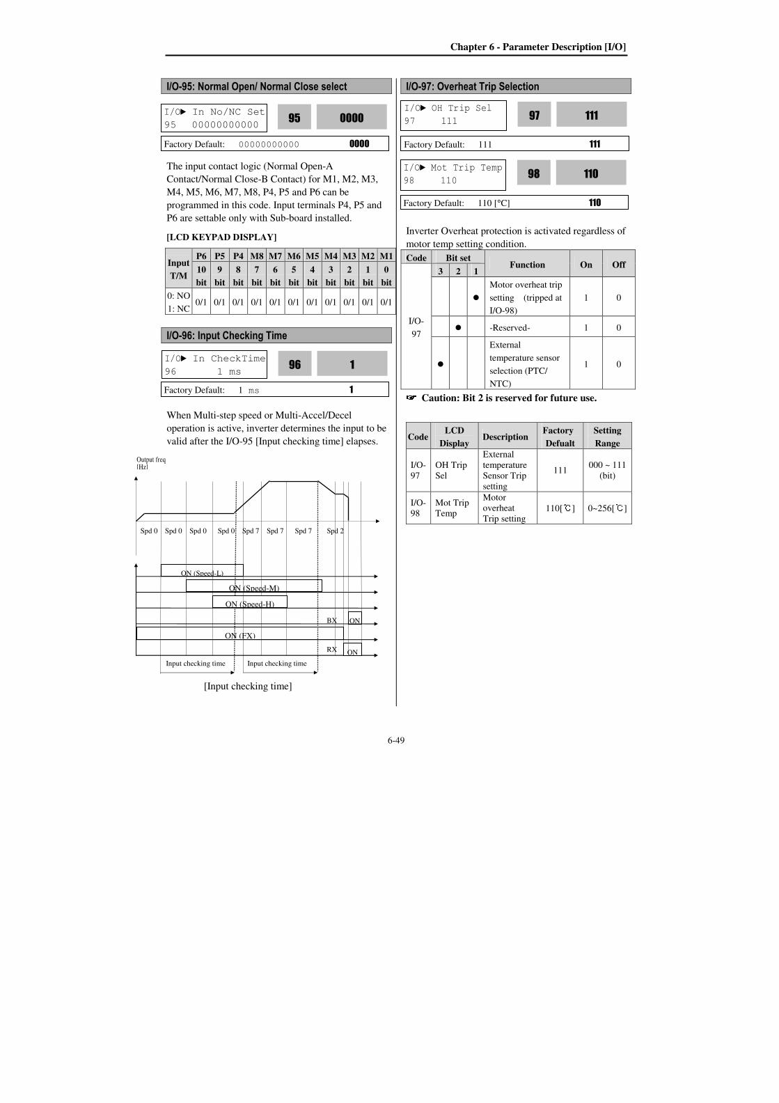
Chapter 6 - Parameter Description [I/O]
6-49
I/O-95: Normal Open/ Normal Close select
The input contact logic (Normal Open-A
Contact/Normal Close-B Contact) for M1, M2, M3,
M4, M5, M6, M7, M8, P4, P5 and P6 can be
programmed in this code. Input terminals P4, P5 and
P6 are settable only with Sub-board installed.
[LCD KEYPAD DISPLAY]
Input
T/M
P6 P5 P4 M8 M7 M6 M5 M4 M3 M2 M1
10
bit
9
bit
8
bit
7
bit
6
bit
5
bit
4
bit
3
bit
2
bit
1
bit
0
bit
0: NO
1: NC 0/1 0/1 0/1 0/1 0/1 0/1 0/1 0/1 0/1 0/1 0/1
I/O-96: Input Checking Time
When Multi-step speed or Multi-Accel/Decel
operation is active, inverter determines the input to be
valid after the I/O-95 [Input checking time] elapses.
I/O-97: Overheat Trip Selection
Inverter Overheat protection is activated regardless of
motor temp setting condition.
Code Bit set Function On Off
I/O-
97
3 2 1
Motor overheat trip
setting (tripped at
I/O-98)
1 0
-Reserved- 1 0
External
temperature sensor
selection (PTC/
NTC)
1 0 Caution: Bit 2 is reserved for future use.
Code LCD
Display Description
Factory
Defualt
Setting
Range
I/O-
97
OH Trip
Sel
External
temperature
Sensor Trip
setting
111 000 ~ 111
(bit)
I/O-
98
Mot Trip
Temp
Motor
overheat
Trip setting 110[] 0~256[]
I/O In No/NC Set
95 00000000000 0000 95
Factory Default: 00000000000 0000
I/O In CheckTime
96 1 ms 1 96
Factory Default: 1 ms 1
I/O OH Trip Sel
97 111 111 97
Factory Default: 111 111
I/O Mot Trip Temp
98 110 110 98
Factory Default: 110 [°C] 110
ON (Speed-L)
Spd 0 Spd 0 Spd 0 Spd 0 Spd 7 Spd 7 Spd 7 Spd 2
BX
RX
Output freq [Hz]
[Input checking time]
ON
ON (FX)
ON (Speed-H)
ON (Speed-M)
ON
Input checking time Input checking time
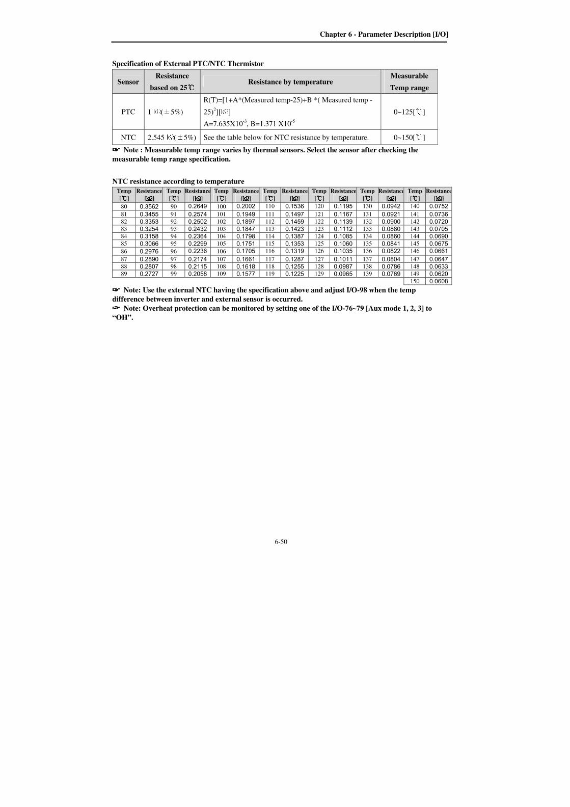
Chapter 6 - Parameter Description [I/O]
6-50
Specification of External PTC/NTC Thermistor
Sensor Resistance
based on 25 Resistance by temperature
Measurable
Temp range
PTC 1(±5%)
R(T)=[1+A*(Measured temp-25)+B *( Measured temp -
25)2][]
A=7.635X10⁻³
, B=1.371 X10⁻⁵
0~125[]
NTC 2.545(±5%) See the table below for NTC resistance by temperature. 0~150[] Note : Measurable temp range varies by thermal sensors. Select the sensor after checking the
measurable temp range specification.
NTC resistance according to temperature
Temp
[]
Resistance
[]
Temp
[]
Resistance
[]
Temp
[]
Resistance
[]
Temp
[]
Resistance
[]
Temp
[]
Resistance
[]
Temp
[]
Resistance
[]
Temp
[]
Resistance
[]
80 0.3562 90 0.2649 100 0.2002 110 0.1536 120 0.1195 130 0.0942 140 0.0752
81 0.3455 91 0.2574 101 0.1949 111 0.1497 121 0.1167 131 0.0921 141 0.0736
82 0.3353 92 0.2502 102 0.1897 112 0.1459 122 0.1139 132 0.0900 142 0.0720
83 0.3254 93 0.2432 103 0.1847 113 0.1423 123 0.1112 133 0.0880 143 0.0705
84 0.3158 94 0.2364 104 0.1798 114 0.1387 124 0.1085 134 0.0860 144 0.0690
85 0.3066 95 0.2299 105 0.1751 115 0.1353 125 0.1060 135 0.0841 145 0.0675
86 0.2976 96 0.2236 106 0.1705 116 0.1319 126 0.1035 136 0.0822 146 0.0661
87 0.2890 97 0.2174 107 0.1661 117 0.1287 127 0.1011 137 0.0804 147 0.0647
88 0.2807 98 0.2115 108 0.1618 118 0.1255 128 0.0987 138 0.0786 148 0.0633
89 0.2727 99 0.2058 109 0.1577 119 0.1225 129 0.0965 139 0.0769 149 0.0620
150 0.0608 Note: Use the external NTC having the specification above and adjust I/O-98 when the temp
difference between inverter and external sensor is occurred. Note: Overheat protection can be monitored by setting one of the I/O-76~79 [Aux mode 1, 2, 3] to
“OH”.
Chapter 6 - Parameter Description [APP]
6-51
6.5 Application group [APP]
APP-00: Jump to desired code #
Jumping directly to any parameter code can be
accomplished by entering the desired code number.
This code is available only with LCD keypad.
APP-01: Application Mode Selection
This code sets the application mode.
APP-01 Set data Description
None Application mode is not selected.
(Factory Default)
MMC
MMC (Multi-Motor Control) mode is
selected in application group. Related
parameters (APP-40~71) are displayed. I/O-76~79 [Programmable digital Aux. relay output] is automatically set to
“MMC.” If less than 4 aux motors are
connected, the remainder relays can be
used for other functions. Caution: I/O-76~79 value is not initialized
automatically even though “None” is set after
setting “MMC”. In this case, set the I/O-76~79
again for desired selection.
APP-02: PID Operation Selection
This function can be used for Process control like
flow, pressure, and air volume control.
To use this function, set APP-02 [proc PI mode] to
“Yes”. PID control detects the amount of feedback
from a sensor and compares it with the target value.
If the values differ, this function produces an output
to eliminate the deviation. In other words, this control
matches the feedback amount with the target value.
For HVAC or Pump applications, the PID control can
be used to adjust the actual output by comparing a
feedback with a ‘Set-point’ given to the inverter. This
‘Set-point’ can be in the form of Speed, Temperature,
Pressure, Flow level, etc. The ‘Set-point’ and the
feedback signals are provided externally to the
inverter analog input terminals. The inverter
compares the signals in calculating ‘total-error’
which is reflected in the inverter output.
Note: PID control can be bypassed to manual
operation temporarily by defining one of the
Programmable input terminals (M1~M8, P4~P6)
to “Open-loop”. The inverter will change to
manual operation from PID control when this
terminal is ON, and change back to PID control
when this terminal is OFF.
[P Control] An error will be occurred for the input during steady
state when P control used alone without I control.
This control is to compensate the error for a system
input proportionally. This is used to make the
controller to respond fast for an error. When P
control is used alone, the system is easily affected by
an external disturbance during steady state. If I
Control is included, error can be eliminated.
[I Control]
I control system to plant is unstable for Integral Gain
Ki. This is to compensate the error of a system
integrally but it makes the system unstable. This is
used to compensate the steady state error by
accumulating them. Using this control alone makes
the system unstable and that application is rarely used.
PI control is usually used to eliminate the error for
the input during steady state.
[PI control]
If PI control is stable for the input (base input,
disturbance), the error will not be occurred.
This control is stable in many systems. If “D control”
is added, it becomes the 3rd
order system. In some
systems this may lead to system instability since
Proportional gain Kp is incresed .
APP Proc PI mode
02 No 0
02
Factory Default: No 0
APP Jump code
00 1
Factory Default: 1
APP App. mode
01 None 0
01
Factory Default: None 0
Chapter 6 - Parameter Description [APP]
6-52
[D Control]
Since the D control uses the variation ratio of error, it
has the merit of controlling the error before the error
is too large. The D control requires a large control
quantity at start, but has the tendency of increasing
the stability of the system. This control does not
affect the steady state error directly, but increases the
system gain because it has an attenuation effect on
the system. As a result, the differential control
component has an effect on decreasing the steady
state error. Since the D control operates on the error
signal, it cannot be used alone. Always use it with the
P control or PI control.
Parameter setting example for PID operation
① Set APP-02 [PID operation selection] to “Yes.” ② Set APP-06 [PID feedback selection] among I,
V1 and Pulse. ③ Set the unit to view feedback value in I/O-86~88
[User unit selection]. Then, all the unit related to
inverter target frequency is changed. ④ Set the appropriate value in APP-04~05 (Refer to
the following PID block diagram). ⑤ When APP-04 is set to “No,” DRV-04 [Freq
Mode] becomes PID reference. If APP-04 is set to
“Yes”, the value set in APP-05 becomes PID
reference. If setting one of I/O-20~27 [Programmable
digital input terminal selection] to “Open loop” and
tuning On/Off the selected terminal, it is decided
whether DRV-04 [Freq Mode] becomes Target freq
or Target freq becomes PID Output.

Chapter 6 - Parameter Description [APP]
6-53
In general, the PID output becomes inverter’s “Target Freq”. In this case, PID is controlling the whole system
and the PID output becomes the target freq of the system and inverter is operating according to Accel/Decel
Time. PID control sampling time is 10msec.
APP-11
APP-12
APP-13
PID P gain
PID I gain
PID D gain
KP
KI
KD
0
I/O-20~27
Multi-function input
terminal setting
(M1~M8)
iTerm Clear
KP
2K
APP-17 PID P2 gain
P Gain2
APP-18 PID P gain scale
PID
Target Freq.Deviation
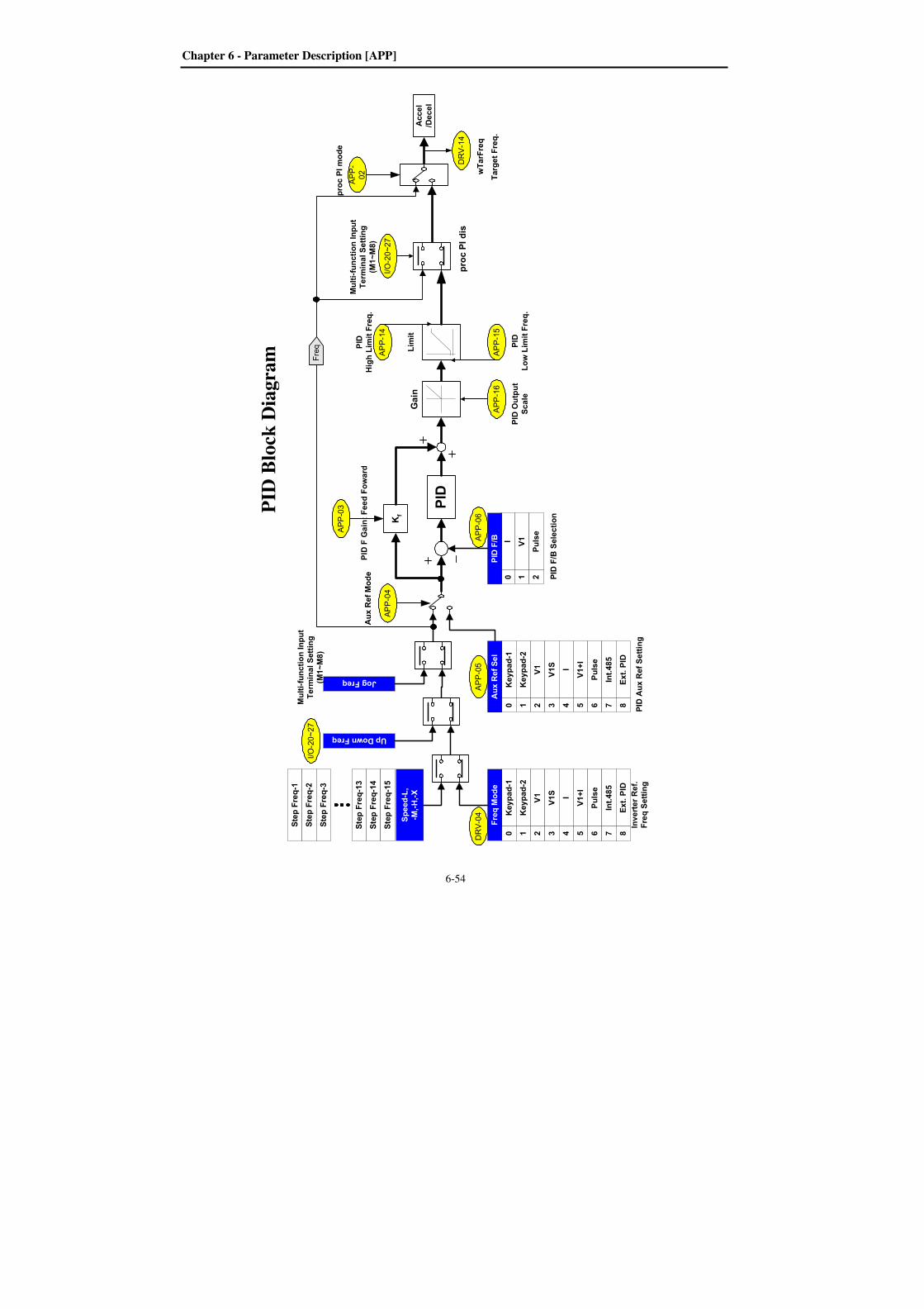
Chapter 6 - Parameter Description [APP]
6-54
PID F/B Selection
Accel
/Decel
wTarFreq
DRV-14
Target Freq.
APP-
02
proc PI mode
PID
Kf
Limit
APP-14
PID
High Limit Freq.
proc PI dis
APP-16
Gain
APP-15
PID
Low Limit Freq.
I/O-20~27
Multi-function Input
Terminal Setting
(M1~M8)
PID Output
Scale
PID F Gain: Feed Foward
DRV-04
PID Aux Ref Setting
Freq
APP-03
APP-04
Aux Ref Mode
Keypad-1
Keypad-2
V1
V1S I
V1+I
Pulse
Int.485
Ext. PID
Aux Ref Sel
0 1 2 3 4 5 6 7 8Jog Freq
Up Down Freq
Keypad-1
Keypad-2
V1
V1S I
V1+I
Pulse
Int.485
Ext. PID
Freq Mode
0 1 2 3 4 5 6 7 8
V1I
Pulse
PID F/B
0 1 2
APP-05
I/O-20~27
Multi-function Input
Terminal Setting
(M1~M8)
Step Freq-1
Step Freq-2
Step Freq-3
Step Freq-13
Step Freq-14
Step Freq-15
Speed-L,
-M,-H,-X
APP-06
Inverter Ref.
Freq Setting
PID
Blo
ck D
iagra
m
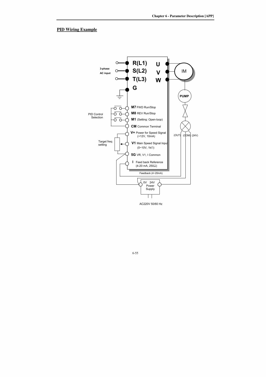
Chapter 6 - Parameter Description [APP]
6-55
PID Wiring Example
PID Control Selection
3-phase
AC input
U
V
W
G
R(L1)
S(L2)
T(L3)
M7 FWD Run/Stop
M8 REV Run/Stop
M1 (Setting: Open-loop)
CM Common Terminal
IM
V+ Power for Speed Signal (+12V, 10mA)
V1 Main Speed Signal Input
(0~10V, 1kΩ) I Feed back Reference (4-20 mA, 250Ω) 5G VR, V1, I Common
0V 24V Power Supply
AC220V 50/60 Hz
(OUT) (COM) (24V)
Feedback (4~20mA)
Target freq setting
PUMP
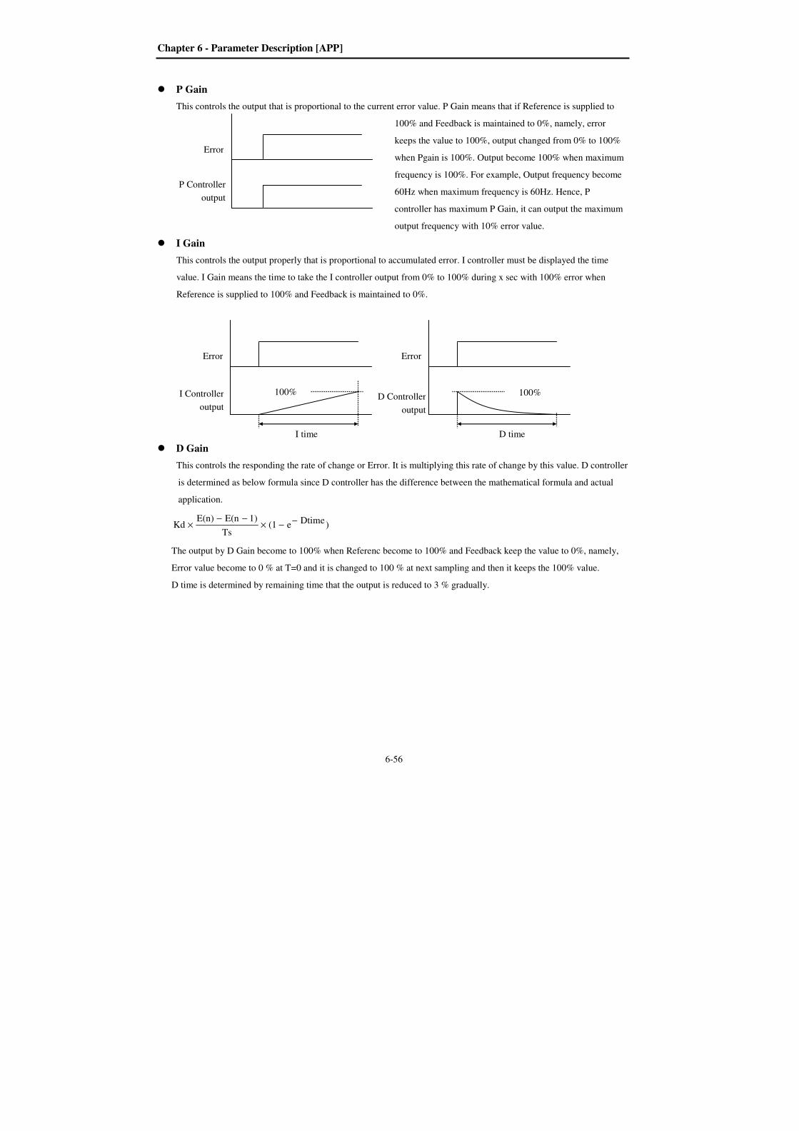
Chapter 6 - Parameter Description [APP]
6-56
P Gain
This controls the output that is proportional to the current error value. P Gain means that if Reference is supplied to
100% and Feedback is maintained to 0%, namely, error
keeps the value to 100%, output changed from 0% to 100%
when Pgain is 100%. Output become 100% when maximum
frequency is 100%. For example, Output frequency become
60Hz when maximum frequency is 60Hz. Hence, P
controller has maximum P Gain, it can output the maximum
output frequency with 10% error value.
I Gain
This controls the output properly that is proportional to accumulated error. I controller must be displayed the time
value. I Gain means the time to take the I controller output from 0% to 100% during x sec with 100% error when
Reference is supplied to 100% and Feedback is maintained to 0%.
D Gain
This controls the responding the rate of change or Error. It is multiplying this rate of change by this value. D controller
is determined as below formula since D controller has the difference between the mathematical formula and actual
application.
)Dtimee(1Ts
1)E(nE(n)Kd −−×
−−×
The output by D Gain become to 100% when Referenc become to 100% and Feedback keep the value to 0%, namely,
Error value become to 0 % at T=0 and it is changed to 100 % at next sampling and then it keeps the 100% value.
D time is determined by remaining time that the output is reduced to 3 % gradually.
Error
P Controller
output
Error
I Controller
output
I time 100%
Error
D Controller
output
D time
100%

Chapter 6 - Parameter Description [APP]
6-57
APP-03: PID F Gain Selection APP-04: PID Aux. Reference Mode Selection APP-05: PID Aux. Reference Selection
This code sets F Gain for use in Feed Forward
control.
When it is set to 100%, the responsiveness (%) of
output F gain from the controller reference value is
100%. Used when fast response is needed.
Caution: Control System output may become
unstable if this value is set too high.
This code selects PID Aux Ref. Input Enable/Disable.
See PID Block Diagram for details.
This code sets the source of Aux reference signal.
Caution: When APP-04 is set to “No,” DRV-04,
Multi-step frequency, UP/DOWN, Jog frequency
become PID controller’s reference and when set to
“Yes,” PID reference is issued from the set value
in APP-05 [PID Aux Reference signal selection] .
APP-06: PID Feedback Signal Selection APP-07: Meter I Max Value APP-08: Meter V Max Value APP-09: Meter P Max Value
Select the feedback signal for PID control. This can
be set one of ‘I’ (4-20mA), ‘V1’ (0~12V) and ‘Pulse’
(A0 and B0, 0~100kHz). Refer to I/O-06~10 for I,
I/O-01~05 for V1, I/O-11~16 for Pulse.
APP-07 [Meter I Max], APP-08 [Meter V Max],
APP-09 [Meter P Max] are can be set according to
APP-06 selection. FeedBack depends on system or
sensor specification. Therefore, By using Max value
of Feedback in calculation. Next Figure shows Max
Feedback Max value is 10V and 5V respectively.
[FeedBack for Max value setting]
APP PID F/B
06 I 0
06
Factory Default: I 0
APP meter I max
07 20mA 20
07
Factory Default: 20mA 20
APP meter V max
08 10 V 10
08
Factory Default: 10 V 10
APP meter P max
09 100 kHz 100
09
Factory Default: 100 kHz 100
APP PID F-Gain
03 0.0 % 0.0
03
Factory Default: 0.0% 0.0
APPAux Ref Mode
04 No 0
04
Factory Default: No 0
APP Aux Ref Sel
05 V1 2
05
Factory Default: V1 2
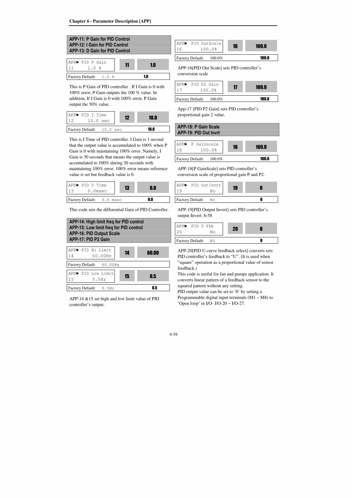
Chapter 6 - Parameter Description [APP]
6-58
APP-11: P Gain for PID Control APP-12: I Gain for PID Control APP-13: D Gain for PID Control
This is P Gain of PID controller . If I Gain is 0 with
100% error, P Gain outputs the 100 % value. In
addition, If I Gain is 0 with 100% error, P Gain
output the 50% value.
This is I Time of PID controller. I Gain is 1 second
that the output value is accumulated to 100% when P
Gain is 0 with maintaining 100% error. Namely, I
Gain is 30 seconds that means the output value is
accumulated to 100% during 30 seconds with
maintaining 100% error. 100% error means reference
value is set but feedback value is 0.
This code sets the differential Gain of PID Controller.
APP-14: High limit freq for PID control APP-15: Low limit freq for PID control APP-16: PID Output Scale
APP-17: PID P2 Gain
APP-14 &15 set high and low limit value of PID
controller’s output.
APP-16[PID Out Scale] sets PID controller’s
conversion scale
App-17 [PID P2 Gain] sets PID controller’s
proportional gain 2 value.
APP-18: P Gain Scale APP-19: PID Out Invrt
APP-18[P GainScale] sets PID controller’s
conversion scale of proportional gain P and P2.
APP-19[PID Output Invert] sets PID controller’s
output Invert. 6-58
APP-20[PID U curve feedback select] converts sets
PID controller’s feedback to “U”. (It is used when
“square” operation as a proportional value of sensor
feedback.)
This code is useful for fan and pumps application. It
converts linear pattern of a feedback sensor to the
squared pattern without any setting.
PID output value can be set to ‘0’ by setting a
Programmable digital input terminals (M1 ~ M8) to
‘Open loop’ in I/O- I/O-20 ~ I/O-27.
APP PID P Gain
11 1.0 % 1.0
11
Factory Default: 1.0 % 1.0
APP PID I Time
12 10.0 sec 10.0
12
Factory Default: 10.0 sec 10.0
APP PID D Time
13 0.0msec 0.0
13
Factory Default: 0.0 msec 0.0
APP PID P2 Gain
17 100.0% 100.0
17
Factory Default: 100.0% 100.0
APP PID Hi Limit
14 60.00Hz 60.00
14
Factory Default: 60.00Hz
APP PID OutScale
16 100.0% 100.0
16
Factory Default: 100.0% 100.0
APP PID Low Limit
15 0.5Hz 0.5
15
Factory Default: 0.5Hz 0.5
APP P Gainscale
18 100.0% 100.0
18
Factory Default: 100.0% 100.0
APP PID OutInvrt
19 No 0
19
Factory Default: NO 0
APP PID U Fbk
20 No 0
20
Factory Default: NO 0

Chapter 6 - Parameter Description [APP]
6-59
The accumulated value by I-Gain can be set to ‘0’ by
setting a Programmable digital input terminal (M1 ~
M8) to ‘iTerm Clear’ in I/O-20 ~ I/O-27.
The P-Gain 2 can be selected for PID controller by
setting a Programmable digital input (I/O-20 ~ I/O-27)
to ‘PID P2'.
When APP-02 [PID operation selection] is set to
“Yes,” a desired display unit in I/O-86, -87, -88 [User
Unit selection] is set among Speed, Percent, Bar,
mBar, kPa, Pa, which affects value display of APP-
06[PID feedback selection], all the parameter unit
related to inverter target frequency is changed.
APP-23: PrePID Reference Frequency APP-24: PrePID Exit Level APP-25: PrePID Stop delay
APP-26: Pipe Broken
PrePID is a function that activate before PID
operation in order to run by good condition. For
example, In Winder operation, this function make
accel/decel speed operation before reach a certain
speed of line speed.
APP-23 [PrePID Reference Frequency]
While select PrePID, it is a frequency that output
until PrePID is completed by target frequency.
APP-24 [Pre PID Exit Level]
If the detected value like as pressure is capable to
operate PID in PrePID operation, the PrePID
operation is exit and start PID operation.
APP-25 [Pre PID Stop Delay]
After time that set in this code, if the detected value
is under level than has set for PID operation, the
system has a problem(Ex. The pipe Broken). So it
must be set properly again.
APP-26 [Pipe Broken]
In case that the deteced value is under the APP-24
and maintained over the time setted in APP-25, the
system show “Pipe Broken” concluding the pipe has
a problem.
APP-27: Sleep Delay Time APP-28: Sleep Frequency APP-29: Wake-Up Level
Sleep function is initiated when flow demand is low.
Inverter stops motor when the motor runs below
Sleep Frequency (APP-28) during Sleep Delay Time
(APP-27). While in the sleep state, the drive keeps
monitoring and controlling, and initiates the Wake-
Up function when the real value of the controlling
amount is greatly different from the Wake-Up level
(APP-29) based on Target Level.
APP PrePID Freq
23 0 0
23
Factory Default: 0 0
APP PrePID Exit
24 0 0
24
Factory Default: 0 0
APP PrePID Dly
25 600 600
25
Factory Default: 600 600
APP Pipe Broken
26 No 0
26
Factory Default: No 0
APP Sleep Delay
27 60.0sec 60.0
27
Factory Default: 60.0 sec 60.0
APP Sleep Freq
28 0.00Hz 0.00
28
Factory Default: 0.00Hz 0.00
APP WakeUp level
29 2.0% 2.0
29
Factory Default: 2.0% 2.0
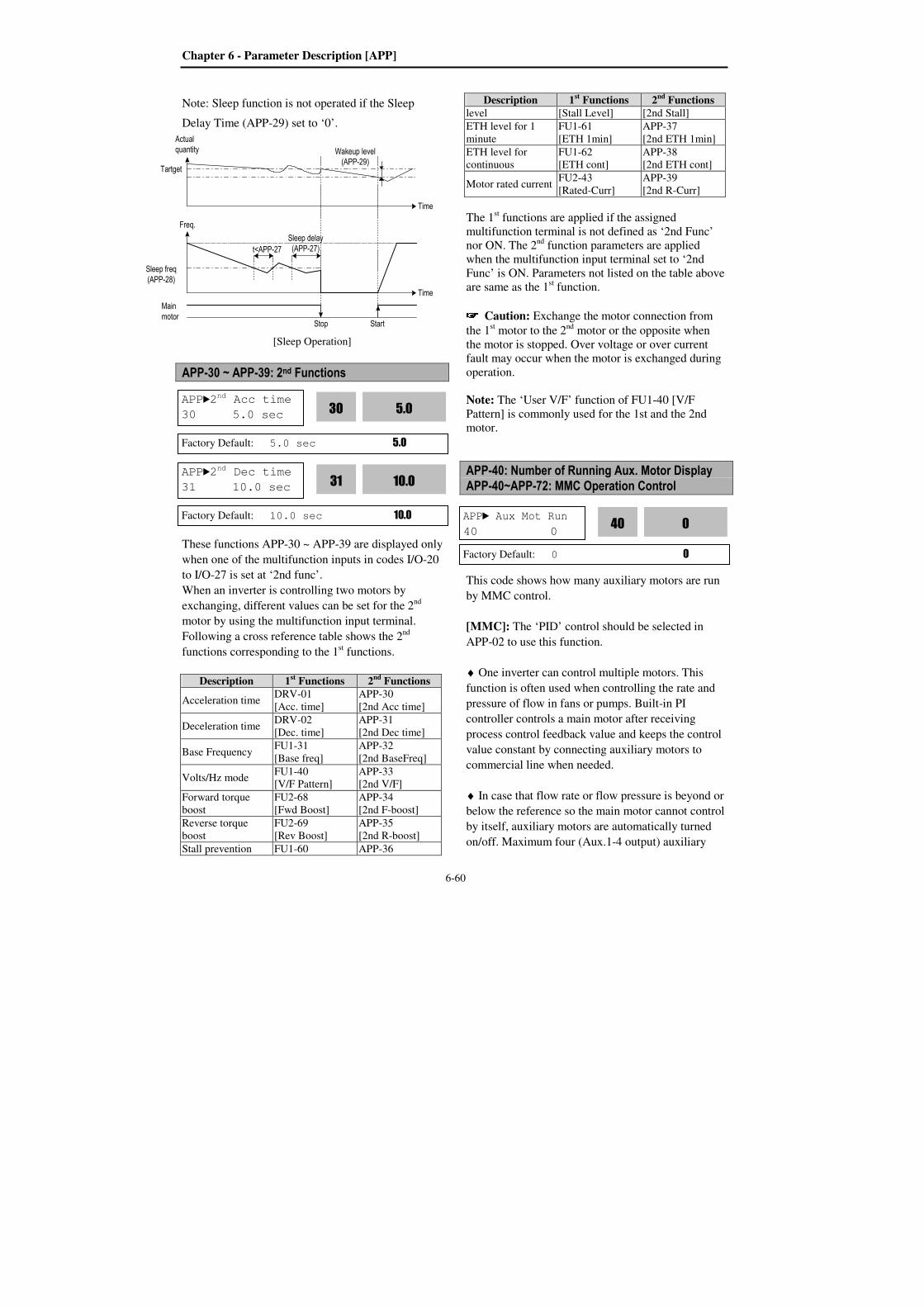
Chapter 6 - Parameter Description [APP]
6-60
Note: Sleep function is not operated if the Sleep
Delay Time (APP-29) set to ‘0’.
[Sleep Operation]
APP-30 ~ APP-39: 2nd Functions
These functions APP-30 ~ APP-39 are displayed only
when one of the multifunction inputs in codes I/O-20
to I/O-27 is set at ‘2nd func’.
When an inverter is controlling two motors by
exchanging, different values can be set for the 2nd
motor by using the multifunction input terminal.
Following a cross reference table shows the 2nd
functions corresponding to the 1st functions.
Description 1st Functions 2nd Functions
Acceleration time DRV-01
[Acc. time]
APP-30
[2nd Acc time]
Deceleration time DRV-02
[Dec. time]
APP-31
[2nd Dec time]
Base Frequency FU1-31
[Base freq]
APP-32
[2nd BaseFreq]
Volts/Hz mode FU1-40
[V/F Pattern]
APP-33
[2nd V/F]
Forward torque
boost
FU2-68
[Fwd Boost]
APP-34
[2nd F-boost]
Reverse torque
boost
FU2-69
[Rev Boost]
APP-35
[2nd R-boost]
Stall prevention FU1-60 APP-36
Description 1st Functions 2nd Functions
level [Stall Level] [2nd Stall]
ETH level for 1
minute
FU1-61
[ETH 1min]
APP-37
[2nd ETH 1min]
ETH level for
continuous
FU1-62
[ETH cont]
APP-38
[2nd ETH cont]
Motor rated current FU2-43
[Rated-Curr]
APP-39
[2nd R-Curr]
The 1st functions are applied if the assigned
multifunction terminal is not defined as ‘2nd Func’
nor ON. The 2nd
function parameters are applied
when the multifunction input terminal set to ‘2nd
Func’ is ON. Parameters not listed on the table above
are same as the 1st function.
Caution: Exchange the motor connection from
the 1st motor to the 2
nd motor or the opposite when
the motor is stopped. Over voltage or over current
fault may occur when the motor is exchanged during
operation. Note: The ‘User V/F’ function of FU1-40 [V/F
Pattern] is commonly used for the 1st and the 2nd
motor.
APP-40: Number of Running Aux. Motor Display APP-40~APP-72: MMC Operation Control
This code shows how many auxiliary motors are run
by MMC control.
[MMC]: The ‘PID’ control should be selected in
APP-02 to use this function.
♦ One inverter can control multiple motors. This
function is often used when controlling the rate and
pressure of flow in fans or pumps. Built-in PI
controller controls a main motor after receiving
process control feedback value and keeps the control
value constant by connecting auxiliary motors to
commercial line when needed.
♦ In case that flow rate or flow pressure is beyond or
below the reference so the main motor cannot control
by itself, auxiliary motors are automatically turned
on/off. Maximum four (Aux.1-4 output) auxiliary
APP Aux Mot Run
40 0 0
40
Factory Default: 0 0
APP2nd Acc time
30 5.0 sec 5.0
30
Factory Default: 5.0 sec 5.0
APP2nd Dec time
31 10.0 sec 10.0
31
Factory Default: 10.0 sec 10.0
t<APP-27Sleep delay(APP-27)
Wakeup level(APP-29)
Sleep freq(APP-28)
Stop Start
Time
Time
Tartget
Freq.
Mainmotor
Actualquantity
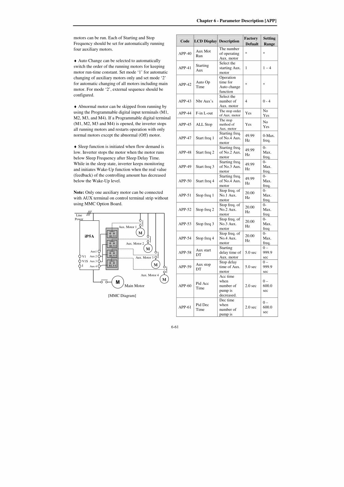
Chapter 6 - Parameter Description [APP]
6-61
motors can be run. Each of Starting and Stop
Frequency should be set for automatically running
four auxiliary motors.
♦ Auto Change can be selected to automatically
switch the order of the running motors for keeping
motor run-time constant. Set mode ‘1’ for automatic
changing of auxiliary motors only and set mode ‘2’
for automatic changing of all motors including main
motor. For mode ‘2’, external sequence should be
configured.
♦ Abnormal motor can be skipped from running by
using the Programmable digital input terminals (M1,
M2, M3, and M4). If a Programmable digital terminal
(M1, M2, M3 and M4) is opened, the inverter stops
all running motors and restarts operation with only
normal motors except the abnormal (Off) motor.
♦ Sleep function is initiated when flow demand is
low. Inverter stops the motor when the motor runs
below Sleep Frequency after Sleep Delay Time.
While in the sleep state, inverter keeps monitoring
and initiates Wake-Up function when the real value
(feedback) of the controlling amount has decreased
below the Wake-Up level.
Note: Only one auxiliary motor can be connected
with AUX terminal on control terminal strip without
using MMC Option Board.
[MMC Diagram]
Code LCD Display Description Factory
Defualt
Setting
Range
APP-40 Aux Mot
Run
The number
of operating
Aux. motor
* *
APP-41 Starting
Aux
Select the
starting Aux.
motor
1 1 – 4
APP-42 Auto Op
Time
Operation
time for
Auto change
function
* *
APP-43 Nbr Aux’s
Select the
number of
Aux. motor
4 0 - 4
APP-44 F-in L-out The stop order
of Aux. motor Yes
No
Yes
APP-45 ALL Stop The stop
method of
Aux. motor Yes
No
Yes
APP-47 Start freq 1
Starting freq.
of No.4 Aux.
motor
49.99
Hz
0-Max.
freq.
APP-48 Start freq 2
Starting freq.
of No.2 Aux.
motor
49.99
Hz
0-
Max.
freq.
APP-49 Start freq 3
Starting freq.
of No.3 Aux.
motor
49.99
Hz
0-
Max.
freq.
APP-50 Start freq 4
Starting freq.
of No.4 Aux.
motor
49.99
Hz
0-
Max.
freq.
APP-51 Stop freq 1
Stop freq. of
No.1 Aux.
motor
20.00
Hz
0-
Max.
freq.
APP-52 Stop freq 2
Stop freq. of
No.2 Aux.
motor
20.00
Hz
0-
Max.
freq
APP-53 Stop freq 3
Stop freq. of
No.3 Aux.
motor
20.00
Hz
0-
Max.
freq
APP-54 Stop freq 4
Stop freq. of
No.4 Aux.
motor
20.00
Hz
0-
Max.
freq.
APP-58 Aux start
DT
Starting
delay time of
Aux. motor
5.0 sec
0 –
999.9
sec
APP-59 Aux stop
DT
Stop delay
time of Aux.
motor
5.0 sec
0 –
999.9
sec
APP-60 Pid Acc
Time
Acc time
when
number of
pump is
decreased.
2.0 sec
0 –
600.0
sec
APP-61 Pid Dec
Time
Dec time
when
number of
pump is
2.0 sec
0 –
600.0
sec
V1
V1S
I
M
M
M
MM
iP5A
Line
Power
Main Motor
Aux. Motor 4
Aux. Motor 3
Aux. Motor 2
Aux. Motor 1
RLY1
RLY2
RLY3
RLY4
Aux1
Aux 2
Aux 3
Aux 4
Chapter 6 - Parameter Description [APP]
6-62
Code LCD Display Description Factory
Defualt
Setting
Range
increased.
APP-62 Regul
Bypass
Select the
Bypass No
No
Yes
APP-63 Sleep
Delay
Sleep delay
time 60 sec
0 –
999.9
sec
APP-64 Sleep Freq Sleep freq. 0.0 Hz 0-max.
freq.
APP-65 WakeUp
level
WakeUp
Level 35.0 %
0.0 –
100.0
%
APP-66 AutoCh_M
ode
Select Auto-
change
mode
0 0 - 2
APP-67 AutoEx-
intv
Time of
Auto-change 72:00
00:00 –
99:00
APP-68 AutoEx-
Freq
Frequencyof
Auto-change
20.00
Hz
0 –
max.
freq.
APP-69 Inter-lock Select Inter-
lock No
No
Yes
APP-71 Aux Stt
Diff
Differenceof
starting
pressure of
Aux motor
2% 0 –
100%
APP-72 Aux Stp
Diff
Differnece
of stop
pressure of
Aux motor
2% 0 –
100%
APP-40 [Aux Mot Run] shows how many auxiliary
motors are run by MMC control.
APP-41 [Starting Aux motor] defines the starting
auxiliary motor for MMC control.
APP-42 [Auto Op Time] displays the operation time
after Auto Change is accomplished.
APP-43 [Number of Aux] sets the number of
auxiliary motors connected to the inverter.
APP-44 [F-in L-out] defines the stop order of
auxiliary motor.
If it is set to ‘Yes’, first started motor will be stop
later (FILO: First Input Last Ouput). If it is set to
‘No’, first started motor will be stop first (First Input
First Output).
For example, auxiliary motor is started in the order of
No.1 motor → No.2 motor → No.3 motor → No.4
motor,
If APP-44 is set to ‘Yes’, auxiliary motor will be stop
in the order of No.4 motor → No.3 motor → No.2
motor → No.1 motor. If it is set to ‘No’, the order is
opposite No.1 motor → No.2 motor → No.3 motor
→ No.4 motor.
APP-45 [ALL Stop] defines the stop method of aux.
motor when motor is stop.
If it is set to ‘Yes’, auxiliary motor will be stop
simultaneously. If not, auxiliary motor will be stop
respectively with the APP-44 set order.
APP-47~50 [No.1~4 Aux motor starting frequency]
sets the starting frequency of each auxiliary motor.
Inverter output frequency will be increased
continuously when the flow pressure or quantity is
lower than the set level.
1) The operation speed of main motor become higher
than the set value in APP-44~50,
2) The delay time set in APP-58 is elapsed,
3) The difference of pressure between command
value and feedback is higher than APP-71,
That is, Auxiliary contact AUX1~4 will be turned On
in this order with above 3 conditions.
APP-51~54 [No.1~4 Aux motor stop frequency] sets
the stop frequency of each auxiliary motor.
The speed of main motor will be decreased by built-
in PID controller when flow pressure or quantity
exceeds.
1) The operation frequency of main motor become
lower than the set value in APP-51~54,
2) The delay time set in APP-59 is elapsed,
3) The difference of pressure is lower than APP-72,
That is auxiliary contact AUX4~AUX1 will be
turned Off in this order with 3 conditions.
APP-58 [Aux.starting delay time], APP-59 [Aux.
stop delay time] sets the time by 0.1 unit the inverter
waits before starting (stop) the auxiliary motors.
APP-41: Starting Auxiliary Motor Selection
This code defines the starting auxiliary motor for
MMC control.
APP Starting Aux
41 1 1
41
Factory Default: 1 1
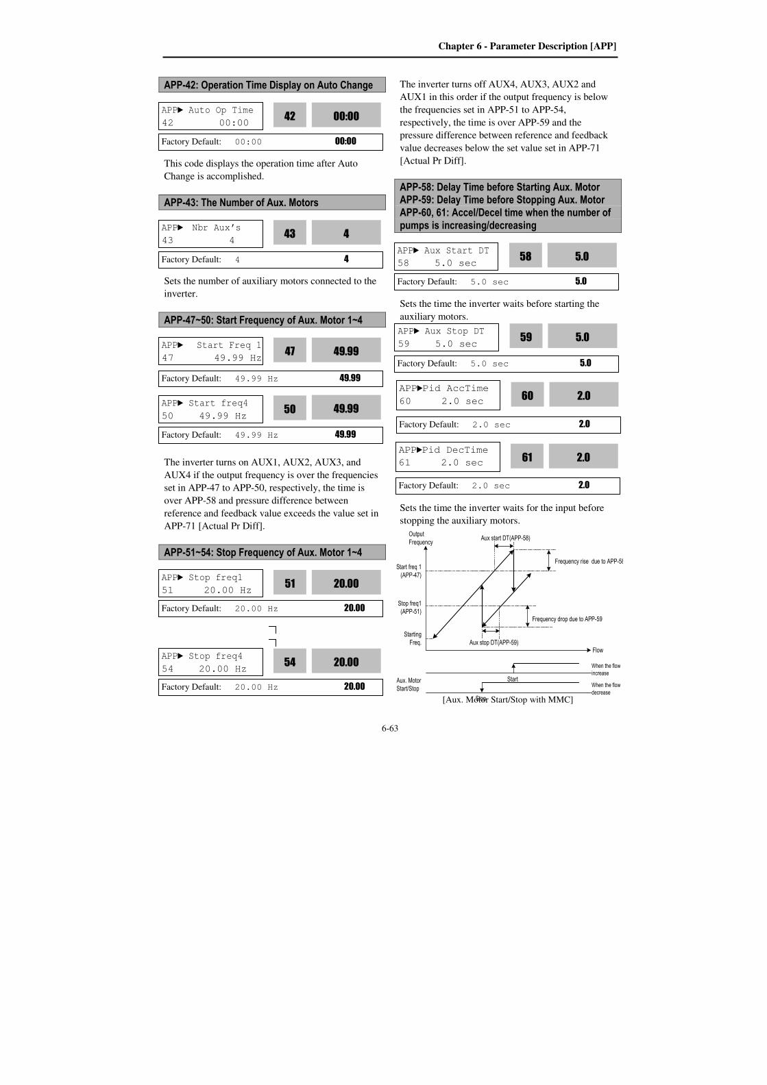
Chapter 6 - Parameter Description [APP]
6-63
When the flow
increase
When the flow
decrease
Start
Stop
Aux. Motor
Start/Stop
Frequency rise due to APP-58
Output
FrequencyAux start DT(APP-58)
Stop freq1
(APP-51)
Starting
Freq. Aux stop DT(APP-59)
Frequency drop due to APP-59
Flow
Start freq 1
(APP-47)
APP-42: Operation Time Display on Auto Change
This code displays the operation time after Auto
Change is accomplished.
APP-43: The Number of Aux. Motors
Sets the number of auxiliary motors connected to the
inverter.
APP-47~50: Start Frequency of Aux. Motor 1~4
The inverter turns on AUX1, AUX2, AUX3, and
AUX4 if the output frequency is over the frequencies
set in APP-47 to APP-50, respectively, the time is
over APP-58 and pressure difference between
reference and feedback value exceeds the value set in
APP-71 [Actual Pr Diff].
APP-51~54: Stop Frequency of Aux. Motor 1~4
The inverter turns off AUX4, AUX3, AUX2 and
AUX1 in this order if the output frequency is below
the frequencies set in APP-51 to APP-54,
respectively, the time is over APP-59 and the
pressure difference between reference and feedback
value decreases below the set value set in APP-71
[Actual Pr Diff].
APP-58: Delay Time before Starting Aux. Motor APP-59: Delay Time before Stopping Aux. Motor APP-60, 61: Accel/Decel time when the number of pumps is increasing/decreasing
Sets the time the inverter waits before starting the
auxiliary motors.
Sets the time the inverter waits for the input before
stopping the auxiliary motors.
[Aux. Motor Start/Stop with MMC]
APP Aux Start DT
58 5.0 sec 5.0
58
Factory Default: 5.0 sec 5.0
Factory Default: 5.0 sec 5.0
APP Aux Stop DT
59 5.0 sec 5.0
59
APP Auto Op Time
42 00:00 00:00
42
Factory Default: 00:00 00:00
APP Start Freq 1
47 49.99 Hz 49.99
47
Factory Default: 49.99 Hz 49.99
APP Start freq4
50 49.99 Hz 49.99
50
Factory Default: 49.99 Hz 49.99
APP Stop freq1
51 20.00 Hz 20.00
51
Factory Default: 20.00 Hz 20.00
APP Stop freq4
54 20.00 Hz 20.00
54
Factory Default: 20.00 Hz 20.00
APP Nbr Aux’s
43 4 4
43
Factory Default: 4 4
APPPid AccTime
60 2.0 sec 2.0
60
Factory Default: 2.0 sec 2.0
APPPid DecTime
61 2.0 sec 2.0
61
Factory Default: 2.0 sec 2.0
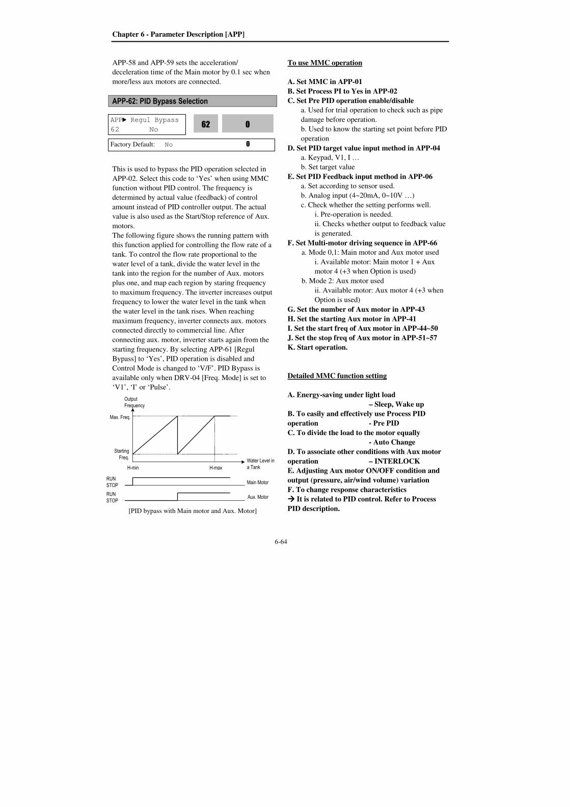
Chapter 6 - Parameter Description [APP]
6-64
APP-58 and APP-59 sets the acceleration/
deceleration time of the Main motor by 0.1 sec when
more/less aux motors are connected.
APP-62: PID Bypass Selection
This is used to bypass the PID operation selected in
APP-02. Select this code to ‘Yes’ when using MMC
function without PID control. The frequency is
determined by actual value (feedback) of control
amount instead of PID controller output. The actual
value is also used as the Start/Stop reference of Aux.
motors.
The following figure shows the running pattern with
this function applied for controlling the flow rate of a
tank. To control the flow rate proportional to the
water level of a tank, divide the water level in the
tank into the region for the number of Aux. motors
plus one, and map each region by staring frequency
to maximum frequency. The inverter increases output
frequency to lower the water level in the tank when
the water level in the tank rises. When reaching
maximum frequency, inverter connects aux. motors
connected directly to commercial line. After
connecting aux. motor, inverter starts again from the
starting frequency. By selecting APP-61 [Regul
Bypass] to ‘Yes’, PID operation is disabled and
Control Mode is changed to ‘V/F’. PID Bypass is
available only when DRV-04 [Freq. Mode] is set to
‘V1’, ‘I’ or ‘Pulse’.
[PID bypass with Main motor and Aux. Motor]
To use MMC operation
A. Set MMC in APP-01
B. Set Process PI to Yes in APP-02
C. Set Pre PID operation enable/disable
a. Used for trial operation to check such as pipe
damage before operation.
b. Used to know the starting set point before PID
operation
D. Set PID target value input method in APP-04
a. Keypad, V1, I …
b. Set target value
E. Set PID Feedback input method in APP-06
a. Set according to sensor used.
b. Analog input (4~20mA, 0~10V …)
c. Check whether the setting performs well.
i. Pre-operation is needed.
ii. Checks whether output to feedback value
is generated.
F. Set Multi-motor driving sequence in APP-66
a. Mode 0,1: Main motor and Aux motor used
i. Available motor: Main motor 1 + Aux
motor 4 (+3 when Option is used)
b. Mode 2: Aux motor used
ii. Available motor: Aux motor 4 (+3 when
Option is used)
G. Set the number of Aux motor in APP-43
H. Set the starting Aux motor in APP-41
I. Set the start freq of Aux motor in APP-44~50
J. Set the stop freq of Aux motor in APP-51~57
K. Start operation.
Detailed MMC function setting
A. Energy-saving under light load
– Sleep, Wake up
B. To easily and effectively use Process PID
operation - Pre PID
C. To divide the load to the motor equally
- Auto Change
D. To associate other conditions with Aux motor
operation – INTERLOCK
E. Adjusting Aux motor ON/OFF condition and
output (pressure, air/wind volume) variation
F. To change response characteristics
It is related to PID control. Refer to Process
PID description.
APP Regul Bypass
62 No 0
62
Factory Default: No 0
Output
Frequency
Max. Freq.
Starting
Freq.
RUN
STOP
RUN
STOP
H-min H-max
Water Level in
a Tank
Main Motor
Aux. Motor
Chapter 6 - Parameter Description [APP]
6-65
APP-66: Auto Change Mode Selection
This function is used to change the running order of
the motors to regulate their run-time when multiple
motors are connected for MMC.
EXCH_NONE mode: Not using Auto Change
Function
The inverter is driving the main motor, and tuning the
relays ON to connect Aux motors. For example,
starting from the Aux motor 3, inverter turns the
relays ON from RLY3 ⇒⇒⇒⇒ RLY4 ⇒⇒⇒⇒ RLY1 ⇒⇒⇒⇒
RLY2 and inverter will start the switching operation
if inverter is run operation. If the number of pump is
decreased, it turns off the aux motors oppositely from
RLY2 ⇒⇒⇒⇒ RLY1 ⇒⇒⇒⇒ RLY4 ⇒⇒⇒⇒ RLY3.
AUX_EXCH mode: Auto Change Function is
applied only to aux. motors.
On/Off sequence is the same as EXCH_NONE
mode. However, the difference is that starting Aux
motor is fixed in EXCH_NONE mode but it is
automatically changed by inverter in AUX_EXCH
mode to prevent a specific motor from overusing. For
example, when Aux motors running order is RLY1 ⇒⇒⇒⇒ RLY2 ⇒⇒⇒⇒ RLY3 ⇒⇒⇒⇒ RLY4 and then the Auto
change condition is met, inverter turns the relay On
from RLY 2⇒⇒⇒⇒ RLY3 ⇒⇒⇒⇒ RLY4 ⇒⇒⇒⇒ RLY1. Caution: EXCH_NONE, AUX_EXCH mode
are available when a Main motor is directly
connected to the Inverter.
MAIN_EXCH mode: Auto Change of Main/Aux
motors.
All motors are connected to relays and operated via
relays. The operation procedure is the same as
AUX_EXCH mode, except that there is no main
motor directly connected to Inverter.
APP-67: Auto Change Time APP-68: Auto Change Level
This function is used to protect motor from running
alone for a long time by changing operation to other
motor.
Auto Change is accomplished when the following
conditions are satisfied:
1) The time set in APP-67 is over and it is
AUX_EXCH mode.
2) The actual value of controlling amount is less than
the value set in APP-68 and all Aux motors Off. (in
AUX_EXCH mode)
3) One motor is running (in MAIN_EXCH mode).
When above three conditions are met, the inverter
stops the running motor, and changes motor to run by
the order set in APP-66 and then continues operation
according to new order. Inverter starts counting only
when auxiliary motor is running.
In MAIN_EXCH mode, when inverter output
frequency is below Auto Change Level, inverter
automatically stops the motor and perform Auto
change function and operates next motor.
APP AutoEx-intv
67 72:00 72:00
67
Factory Default: 72:00 72:00
APP AutoEx-Freq
68 20.00 Hz 20.00
68
Factory Default: 20.00 Hz 20.00
APP AutoCh_Mode
66 0 0
66
Factory Default: 0 0
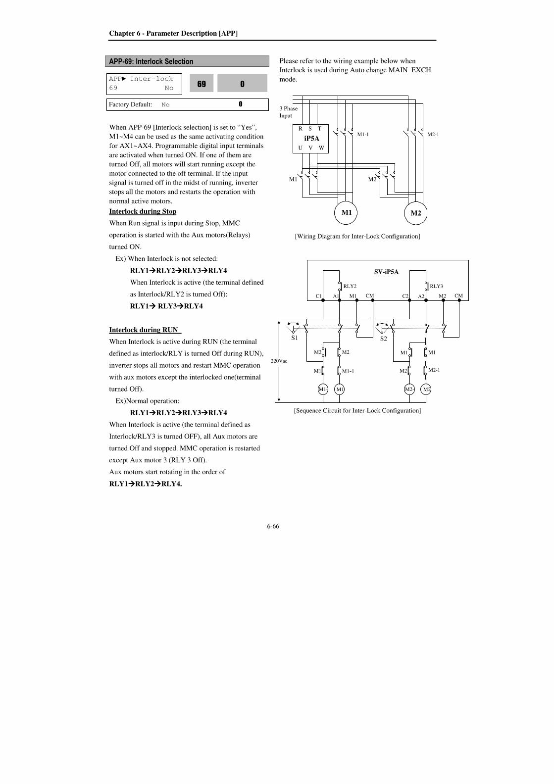
Chapter 6 - Parameter Description [APP]
6-66
APP-69: Interlock Selection
When APP-69 [Interlock selection] is set to “Yes”,
M1~M4 can be used as the same activating condition
for AX1~AX4. Programmable digital input terminals
are activated when turned ON. If one of them are
turned Off, all motors will start running except the
motor connected to the off terminal. If the input
signal is turned off in the midst of running, inverter
stops all the motors and restarts the operation with
normal active motors.
Interlock during Stop
When Run signal is input during Stop, MMC
operation is started with the Aux motors(Relays)
turned ON.
Ex) When Interlock is not selected:
RLY1RLY2RLY3RLY4
When Interlock is active (the terminal defined
as Interlock/RLY2 is turned Off):
RLY1 RLY3RLY4
Interlock during RUN
When Interlock is active during RUN (the terminal
defined as interlock/RLY is turned Off during RUN),
inverter stops all motors and restart MMC operation
with aux motors except the interlocked one(terminal
turned Off).
Ex)Normal operation:
RLY1RLY2RLY3RLY4
When Interlock is active (the terminal defined as
Interlock/RLY3 is turned OFF), all Aux motors are
turned Off and stopped. MMC operation is restarted
except Aux motor 3 (RLY 3 Off).
Aux motors start rotating in the order of
RLY1RLY2RLY4.
Please refer to the wiring example below when
Interlock is used during Auto change MAIN_EXCH
mode.
[Wiring Diagram for Inter-Lock Configuration]
[Sequence Circuit for Inter-Lock Configuration]
APP Inter-lock
69 No 0
69
Factory Default: No 0
3 Phase
Input
M1
M1-1
M2
M2-1
U V W
R S T
iP5A
M1 M2
C1 A1 M1 CM
RLY2
M1-
1 M1
C2 A2 M2 CM
RLY3
M2-
1 M2
M1-1 M1
M2 M2
M2-1 M2
M1 M1
S1 S2
220Vac
SV-iP5A

Chapter 6 - Parameter Description [APP]
6-67
Aux motor starting condition and output
(Pressure, air volume..) adjustment
Inverter turns Aux motors ON automatically when it
is impossible for a main motor to control increased
load, causing shortage in flow rate or flow pressure.
Maximum 4 Aux motors can be used. To turn on the
4 Aux motors automatically, starting frequency for
each motor should be set.
Code LCD Display Description Factory
Defualt
Setting
Range
APP-
47 ~50
Start freq
1~4
Starting freq.
of No.1~4
Aux. motor
49.99
Hz
0 -
Max
Freq.
APP-58 Aux start
DT
Stop delay
time of Aux.
motor
5.0 sec
0 –
999.9
sec
APP-61 Pid Dec
Time
Dec time
when
number of
pump is
increased.
2.0 sec
0 –
600.0
sec
APP-71 Aux Stt
Diff
Differenceof
starting
pressure of
Aux motor
2% 0 –
100%
Aux motor active condition: Main motor speed
exceeds Aux motor starting frequency (APP-47~50),
for the time over APP-58[Aux motor starting delay
time], Difference between PID reference and
Feedback value exceeds APP-71 [Starting Aux motor
pressure difference].
APP-47~50: Frequency to turn Aux motor ON. It
is set the same as main motor frequency
outputting equally when aux motor is turned ON.
APP-58: It should be set greater than system delay
time.
APP-71: It is set by comparing the pressure
difference when Aux motor is turned ON and that
of Aux motor starting frequency.
APP-61: This is the time inverter frequency is
decreased after Aux motor is turned ON. It should
be set higher than System delay time but it causes
Aux motor ON state to become too long.
Aux motor stopping condition and output
(Pressure, air volume..) adjustment
Inverter turns off the Aux motors when flow rate or
flow pressure is too large due to decreased load. For
Inverter to turn off Max 4 Aux motors automatically,
4 stopping frequency should be set separately.
Aux motors are opened when main motor rotates
below APP-51~54 [Aux motor stopping frequency]
for the time over APP-59 [Aux motor stopping delay
time] and pressure difference between PID reference
and Feedback value exceeds the set value in APP-
71[Aux motor starting /stopping pressure difference].
APP-51~57: The Aux motors are turned off at this
frequency. It is set as dF, whose output matches
when Aux motor is off.
(dF = Aux motor On Freq – Aux motor Off Freq)
APP-59: It should be set higher than System Delay
Time.
Aux motor
starting freq.
APP-47~50
Aux motor
starting delay
time APP-58
Starting Aux motor pressure difference APP-71
Aux motor stop freq.
APP 51~54
Inverter Decel Time when
number of Pump increase
APP-61
Aux
motor
Main
motor
Threshold
Stop Aux motor pressure difference APP-72
Aux motor
start freq
APP-44~47
Aux motor
stopping delay
time APP-59
Aux motor stop freq
APP-51~54
Inverter Accel Time when
number of Pump decrease APP-60
Threshold
Feedback

Chapter 6 - Parameter Description [APP]
6-68
APP-60: This is the time inverter frequency is
increased after Aux motor is turned OFF. It
should be set higher than System delay time but it
causes Aux motor OFF state to become too long.
APP-71: Pressure Difference for Aux Motor Start APP-72: Pressure Difference for Aux Motor Stop
It sets the pressure difference between when Aux
motors are ON and Aux motor starting frequency.
APP-80~97: External PID operation
Code LCD Display Default Range
APP-80 Ext PI mode 0 (No) 0 (No)
1 (Yes)
APP-81 Ext Ref Sel 3 (Key-Pad)
0 (I)
1 (V1)
2 (Pulse)
3 (Key-Pad)
APP-82 Ext Ref Perc 50.00 [%] 0 – 100.00 [%]
APP-83 Ext Fbk Sel 0 (I)
0 (I)
1 (V1)
2 (Pulse)
APP-85 ExtPID Pgain 1.0 [%] 0 – 999.9 [%]
APP-86 ExtPID Itime 10.0 [sec] 0 – 32.0 [sec]
APP-87 ExtPID Dtime 0 [msec] 0 – 2000 [msec]
Code LCD Display Default Range
APP-88 ExtPID lmt-H 100.00 [%] 0 – 100.00 [%]
APP-89 ExtPID lmt-L 0.00 [%] 0 – 30.00 [%]
APP-90 ExtPID Scale 100.0 [%] 0 – 999.9
APP-91 Ext P2-gain 100.0 [%] 0 – 999.9
APP-92 Ext P Scale 100.0 [%] 0 – 100.0
APP-93 ExtPID F-gain 0.0 [%] 0 – 999.9 [%]
APP-95 ExtPIDOut Inv 0 (No) 0 (No)
1 (Yes)
APP-97 Ext Loop Time 100 [msec] 50 – 200 [msec]
APP-80~96 setting value is the same as APP-02~17.
APP –82 [Ext PID Ref value] is settable when APP-
81 [Ext PID Ref selection] is set to “Keypad”.
APP–97 [Ext PID Loop Time] sets the time to
activate Ext PID controller. Set the desired value
according to system.
Ext PID can be used for ①controlling other system
independently as an external PID controller ②using
both PID controller in APP-02 and External PID
controller ③using Ext PID output as an Inverter
target frequency. See 10) APP-02, APP-80 (to use Dual PID operation) for more details.
APPAux Stt Diff
71 2% 2
71
Factory Default: 2% 2
APP Ext Ref Sel
81 KeyPad 3
81
Factory Default: KeyPad 3
APPExt Ref Perc
82 50.00% 50.00
82
Factory Default: 50.00% 50.00
APPAux Stp Diff
72 2% 2
72
Factory Default: 2% 2
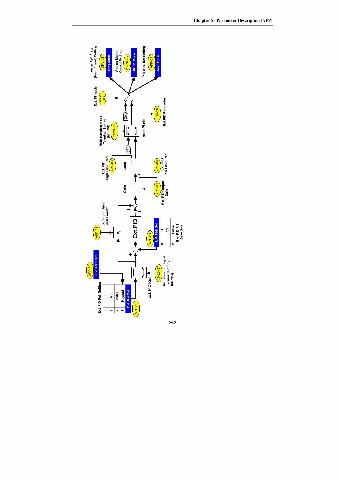
Chapter 6 - Parameter Description [APP]
6-69
Ext. PID F/B
Selection
Ext.PID Parameter
DRV-20
APP-
80
Ext. PI mode
Ext.PID
Kf
Limit
APP-88
Ext. PID
High Limit Freq.
proc PI dis
APP-90
Gain
APP-89
Ext. PID
Low Limit Freq.
I/O-20~27
Multi-function Input
Terminal Setting
(M1~M8)
Ext. PID Output
Gain
Ext. PID F Gain:
Feed Foward
Ext. PID Ref Setting
Zero
APP-93
APP-81
I/O-20~27
Multi-function Input
Terminal Setting
(M1~M8)
APP-83
Keypad
3
V1I
Pulse
0 1 2
V1I
Pulse
Ext. Fbk Sel
0 1 2
Ext. PID Run
Zer
o
APP-82
Ext. Ref Perc
Ext. Ref Sel
APP-05
Aux Ref Sel
S0, S1 Mode
I/O-70,-72
Analog Meter
Output Setting
PID Aux. Ref Setting
DRV-04
Freq Mode
Inverter Ref. Freq
(Main Speed) Setting
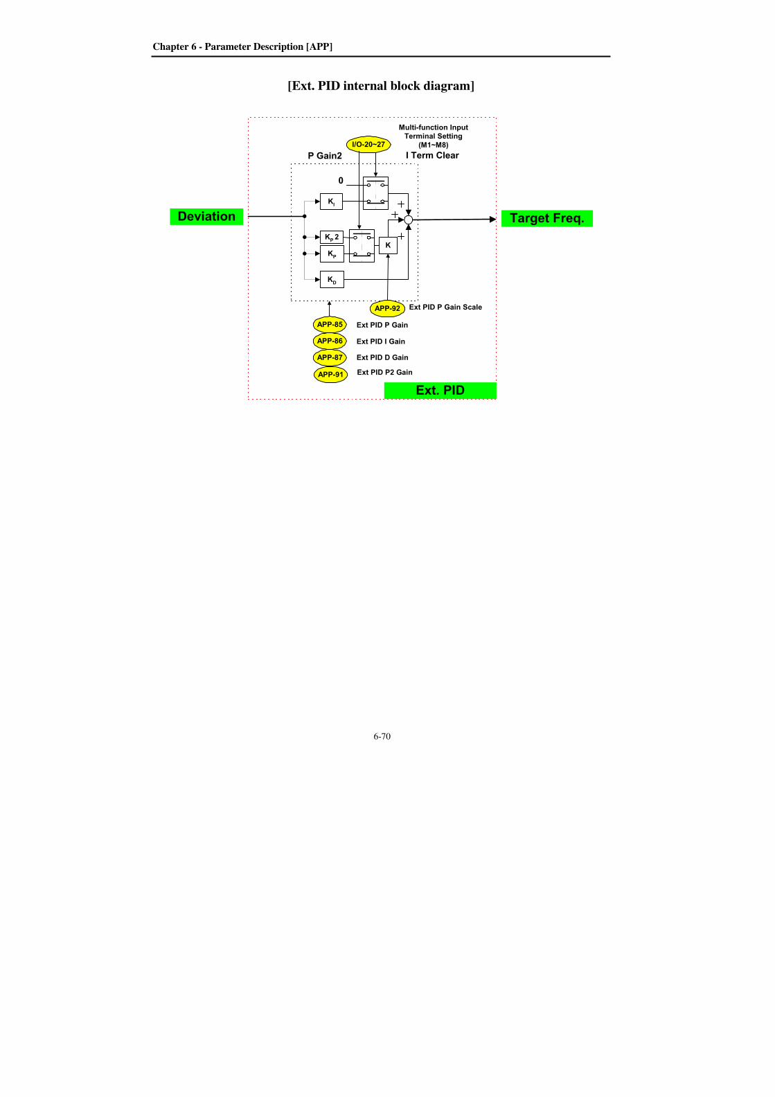
Chapter 6 - Parameter Description [APP]
6-70
[Ext. PID internal block diagram]
APP-85
APP-86
APP-87
Ext PID P Gain
Ext PID I Gain
Ext PID D Gain
KP
KI
KD
0
I/O-20~27
Multi-function InputTerminal Setting
(M1~M8)
I Term Clear
KP 2
K
APP-91 Ext PID P2 Gain
P Gain2
APP-92 Ext PID P Gain Scale
Ext. PID
Target Freq.Deviation
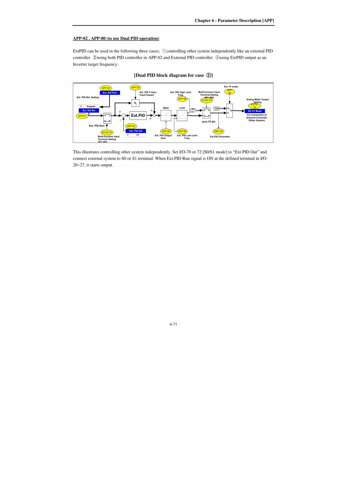
Chapter 6 - Parameter Description [APP]
6-71
APP-02 , APP-80 (to use Dual PID operation)
ExtPID can be used in the following three cases; ①controlling other system independently like an external PID
controller ②using both PID controller in APP-02 and External PID controller ③using ExtPID output as an
Inverter target frequency.
[Dual PID block diagram for case ①①①①]
Ext.PID Parameter
DRV-20
APP-80
Ext. PI mode
Ext.PID
Kf
Limit
APP-88
Ext. PID High LimitFreq.
proc PI dis
APP-90
Gain
APP-89
Ext. PID Low LImitFreq.
I/O-20~27
Multi-function Input
Terminal Setting(M1~M8)
Ext. PID OutputGain
Ext. PID F Gain:Feed Foward
Ext. PID Ref Setting
Zero
APP-93
APP-81
I/O-20~27
Multi-function Input
Terminal Setting(M1~M8)
APP-83Ext. PID Run
Zero
APP-82
Ext. Ref Perc
S0, S1 Mode
I/O-70,-72
Analog Meter OutputSetting
Ext. Fbk Sel
V11
Keypad3
Ext. Ref Sel
For Connection to
External Controller(Other System)
This illustrates controlling other system independently. Set I/O-70 or 72 [S0/S1 mode] to “Ext PID Out” and
connect external system to S0 or S1 terminal. When Ext.PID Run signal is ON at the defined terminal in I/O-
20~27, it starts output.
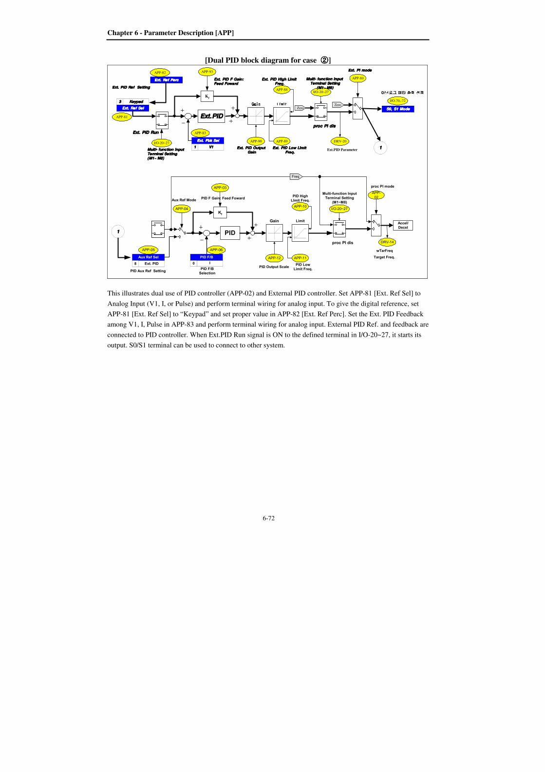
Chapter 6 - Parameter Description [APP]
6-72
[Dual PID block diagram for case ②②②②]
Ext.PID Parameter
DRV-20
APP-80
Ext. PI modeExt. PI modeExt. PI modeExt. PI mode
Ext.PIDExt.PIDExt.PIDExt.PID
Kf LimitLimitLimitLimitAPP-88
Ext. PID High LImit Ext. PID High LImit Ext. PID High LImit Ext. PID High LImit Freq.Freq.Freq.Freq.
proc PI disproc PI disproc PI disproc PI dis
APP-90
GainGainGainGainAPP-89
Ext. PID Low LImit Ext. PID Low LImit Ext. PID Low LImit Ext. PID Low LImit Freq.Freq.Freq.Freq.
I/O-20~27
Multi- function Input Multi- function Input Multi- function Input Multi- function Input Terminal SettingTerminal SettingTerminal SettingTerminal Setting
(M1~ M8)(M1~ M8)(M1~ M8)(M1~ M8)
Ext. PID Output Ext. PID Output Ext. PID Output Ext. PID Output GainGainGainGain
Ext. PID F Gain:Ext. PID F Gain:Ext. PID F Gain:Ext. PID F Gain:Feed FowardFeed FowardFeed FowardFeed Foward
Ext. PID Ref SettingExt. PID Ref SettingExt. PID Ref SettingExt. PID Ref Setting
Zero
APP-93
APP-81
I/O-20~27
Multi- function Input Multi- function Input Multi- function Input Multi- function Input Terminal SettingTerminal SettingTerminal SettingTerminal Setting(M1~ M8)(M1~ M8)(M1~ M8)(M1~ M8)
APP-83Ext. PID RunExt. PID RunExt. PID RunExt. PID Run
Zero
APP-82
Ext. Ref PercExt. Ref PercExt. Ref PercExt. Ref Perc
S0, S1 ModeS0, S1 ModeS0, S1 ModeS0, S1 Mode
I/O-70,-72
아날로그아날로그아날로그아날로그 메타메타메타메타 출력출력출력출력 설정설정설정설정Ext. Fbk SelExt. Fbk SelExt. Fbk SelExt. Fbk Sel
V1V1V1V11111
KeypadKeypadKeypadKeypad3333
Ext. Ref SelExt. Ref SelExt. Ref SelExt. Ref Sel
PID F/BSelection
Accel/Decel
wTarFreq
DRV-14
Target Freq.
APP-02
proc PI mode
PID
Kf
Limit
APP-10
PID HighLImit Freq.
proc PI dis
APP-12
Gain
APP-11
PID LowLimit Freq.
I/O-20~27
Multi-function InputTerminal Setting
(M1~M8)
PID Output Scale
PID F Gain: Feed Foward
PID Aux Ref Setting
Freq
APP-03
APP-04
Aux Ref Mode
APP-05 APP-06
Ext. PID
Aux Ref Sel
8 I
PID F/B
0
1111
1111
This illustrates dual use of PID controller (APP-02) and External PID controller. Set APP-81 [Ext. Ref Sel] to
Analog Input (V1, I, or Pulse) and perform terminal wiring for analog input. To give the digital reference, set
APP-81 [Ext. Ref Sel] to “Keypad” and set proper value in APP-82 [Ext. Ref Perc]. Set the Ext. PID Feedback
among V1, I, Pulse in APP-83 and perform terminal wiring for analog input. External PID Ref. and feedback are
connected to PID controller. When Ext.PID Run signal is ON to the defined terminal in I/O-20~27, it starts its
output. S0/S1 terminal can be used to connect to other system.
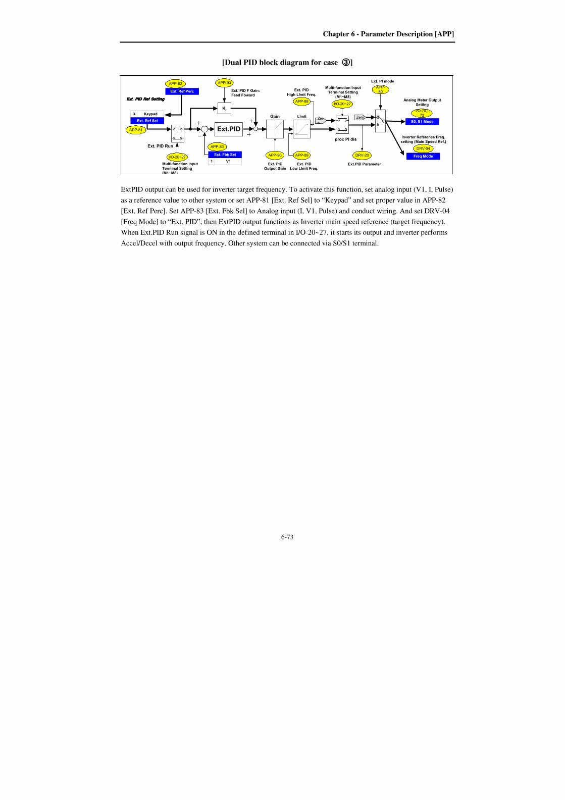
Chapter 6 - Parameter Description [APP]
6-73
[Dual PID block diagram for case ③③③③]
Ext.PID Parameter
DRV-20
APP-80
Ext. PI mode
Ext.PID
Kf
Limit
APP-88
Ext. PID
High LImit Freq.
proc PI dis
APP-90
Gain
APP-89
Ext. PIDLow Limit Freq.
I/O-20~27
Multi-function InputTerminal Setting
(M1~M8)
Ext. PIDOutput Gain
Ext. PID F Gain:Feed Foward
Ext. PID Ref SettingExt. PID Ref SettingExt. PID Ref SettingExt. PID Ref Setting
Zero
APP-93
APP-81
I/O-20~27
Multi-function Input
Terminal Setting(M1~M8)
APP-83Ext. PID Run
Zero
APP-82
Ext. Ref Perc
S0, S1 Mode
I/O-70,-72
Analog Meter Output
Setting
Ext. Fbk Sel
V11
Keypad3
Ext. Ref Sel
DRV-04
Freq Mode
Inverter Reference Freq.setting (Main Speed Ref.)
ExtPID output can be used for inverter target frequency. To activate this function, set analog input (V1, I, Pulse)
as a reference value to other system or set APP-81 [Ext. Ref Sel] to “Keypad” and set proper value in APP-82
[Ext. Ref Perc]. Set APP-83 [Ext. Fbk Sel] to Analog input (I, V1, Pulse) and conduct wiring. And set DRV-04
[Freq Mode] to “Ext. PID”, then ExtPID output functions as Inverter main speed reference (target frequency).
When Ext.PID Run signal is ON in the defined terminal in I/O-20~27, it starts its output and inverter performs
Accel/Decel with output frequency. Other system can be connected via S0/S1 terminal.

Notes :

7-1
CHAPTER 7 - TROUBLESHOOTING & MAINTENANCE
7.1 Fault Display When a fault occurs, the inverter turns off its output and displays the fault status in DRV-12. The last 5 faults
are saved in FU2-01 through FU2-05 with the operation status at the instance of fault. Reset the inverter when a
fault occures.
Keypad Display Protective
Function Description
Over Current
Over Current 1
Over Current
Protection
The inverter turns off its output when the output current of the inverter flows more
than 200% of the inverter rated current. This may cause danger or damage the
drive so it requires double protection.
Ground Fault Ground Fault
Protection
The inverter turns off its output when a ground fault occurs and the ground fault
current is more than the internal setting value of the inverter. Over current trip
function may protect the inverter when a ground fault occurs due to a low ground
fault resistance.
Over Voltage Over voltage
protection
The inverter turns off its output if the DC voltage of the main circuit increases
higher than the rated value when the motor decelerates or when regenerative
energy flows back to the inverter due to a regenerative load. This fault can also
occur due to a surge voltage generated at the power supply system.
Over Load
Current Limit
Protection
(Overload
Protection)
The inverter turns off its output if the output current of the inverter flows at 120%
of the inverter rated current.
Over Heat Inverter
Over Heat
The inverter turns off its output if the heat sink is over heated due to a damaged
cooling fan or an alien substance in the cooling fan.
E-Thermal Electronic
Thermal
The internal electronic thermal of the inverter determines the over heating of the
motor. If the motor is overloaded the inverter turns off the output. The inverter
cannot protect the motor when driving a multi-pole motor or when driving
multiple motors, so consider thermal relays or other thermal protective devices for
each motor.
Overload capacity: 130% for 1 min
Ext. Trip External Trip
Use this function if the user needs to turn off the output by an external trip signal.
(Normal Open Contact) Inverter blocks the output to protect motor overload by
detecting through this terminal.
Low Voltage Low Voltage
Protection
The inverter turns off its output if the DC voltage is below the detection level
because insufficient torque or over heating of the motor can occurs when the input
voltage of the inverter drops.
Over Current 2 IGBT Short The inverter turns off the output if an IGBT short through or an output short
occurs.
Output Phase Open Output Phase
open
The inverter turns off its output when the one or more of the output (U, V, W)
phase is open. The inverter detects the output current to check the phase open of
the output.
Input Phase Open InputPhaseOpen
The inverter turns off its output if the one or more of the input (R, S, T) phase is
open. The inverter detects the intput current to check the phase open of the input.
If smaller load is used, it can not be detected.
BX BX Protection
(Instant Cut Off)
Used for the emergency stop of the inverter. The inverter instantly turns off the
output when the BX terminal is turned ON, and returns to regular operation when
the BX terminal is turned OFF. Take caution when using this function.
HW-Diag Inverter H/W
Fault
A fault signal is output when an error occurs to the control circuitry of the
inverter. There are the Wdog error, the EEP error, Input phase open, NTC open
and the ADC Offset for this fault
COM Error
CPU Error
Communication
Error This fault is displayed when the inverter cannot communicate with the keypad.
Inv. OLT Inverter
Overload
The inverter turns off its output when the output current of the inverter flows more
than the rated level (110% for 1 minute, 130% for 4 seconds).
NTC open NTC Open This fault is displayed when inverter internal NTC is opened.

Chapter 7 - Troubleshooting & Maintenance
7-2
Keypad Display Protective
Function Description
LOP
LOR
LOV
LOI
LOX
Operating
Method when
the Frequency
Reference is
Lost
According to the I/O-48 [Operating Method when the Frequency Reference is
Lost] setting, there are three modes: continuous operation, decelerate to stop, and
free run to stop,
LOP: Displayed when option frequency reference is lost (DPRAM time out)
LOR: Displayed when option frequency reference is lost (Communication
network fault)
LOV: Displayed when ‘V1’ analog frequency reference is lost.
LOI: Displayed when ‘I‘ analog frequency reference is lost.
LOX: Displayed when sub-board (V2, ENC) analog frequency reference is lost.
Lost cmd This fault is diaplayed when I/O 18 sets to Protection.
Fuse Open Fuse Open This fault is displayed when inverter internal fuse is opened by over current.
(applied above 37 kW products)
Output Fault Trip No Motor Trip Trip has occurred according to setting of FU1 57~59.
Keypad Open Keypad FLT Indicats wire is separated from keypad. It is displayed only DRV-23 set to Fault.
To reset fault, Press RESET key, close RST-CM terminals or cycle the input power.
If a problem persists, please contact the factory or your local distributor.
Operation methods and fault display in case of frequency loss
I/O-18 <Lost Command> is as below description
I/O-18 set data Description
None Keep the operation because frequency command is lost.
(Factory default)
FreeRun Free Run to stop because frequency command is lost.
Stop Deceleration to stop because frequency command is lost.
Protection Lost Cmd Trip because frequency command is lost.
Load display when command is lost
LCD display Description LOP Displayed when option command is lost (DPRAM Time out)
LOR Displayed when option command is lost
(Abnormal communication network)
LOV Displayed when V1 analog frequency command is lost.
LOI Displayed when I analog frequency command is lost.
LOX Displayed when sub board (V2, ENC) frequency is lost.
If you want to check the previous state of inverter trip occurred and inverter trip description,
Current faulty description
Code Display Description DRV-7 Over Current Displayed the current trip message. (Over current)
Use the PROG, and key before pressing the RESET key to check the fault content(s) such as output
frequency, output current, and whether the inverter was accelerating, decelerating, or in constant speed at
the time of the fault occurred. Press the ENT key to escape.
Press the RESET key to save the trip history in FU2-01~05.
Chapter 7 - Troubleshooting & Maintenance
7-3
Last fault history
This code displays up to five previous fault (trip) status of the inverter. The lowest numbered fault
such as “Last trip 1” is the most recent. Previous state of inverter trip occurred and inverter trip
description can be checked.
FU2-06 [Erase trips] initializes the FU2-01~05 [Last trip-x]. It becomes the value of factory default.
Code LCD display Description FU2-01 Last trip-1 Trip history 1
FU2-02 Last trip-2 Trip history 2
FU2-03 Last trip-3 Trip history 3
FU2-04 Last trip-4 Trip history 4
FU2-05 Last trip-5 Trip history 5
Reset the trip (Abnormal inverter state)
There are 3 kinds of reset methods. Auto restart number is initialized after reset the inverter.
1. Reset by [RESET] key in loader.
2. Cut off the RST-CM of terminal block of inverter control circuit.
3. Turn off the inverter power and turn on the inverter.
Protection furnction
LCD display Description
Over Current 1
Protection
Over Current
Over Current1
Inverter output cuts off when the inverter output exceeds 200% of
th rated current. 소손의 위함이 있는 만큼 이중 보호 합니다.
Ground Fault
Current Protection Ground Fault
Inverter output cuts off when current above the prescribed amount
flows due to earth in the inverter outputu part. Ground fault due to
low ground resistor can be protective by over current trip.
Over Voltage
Protection Over Voltage
Inverter output cutss off when the DC current above the prescribed
amount flows due to deceleration or regenerative energy. It can be
occurred due to surge voltage from power system.
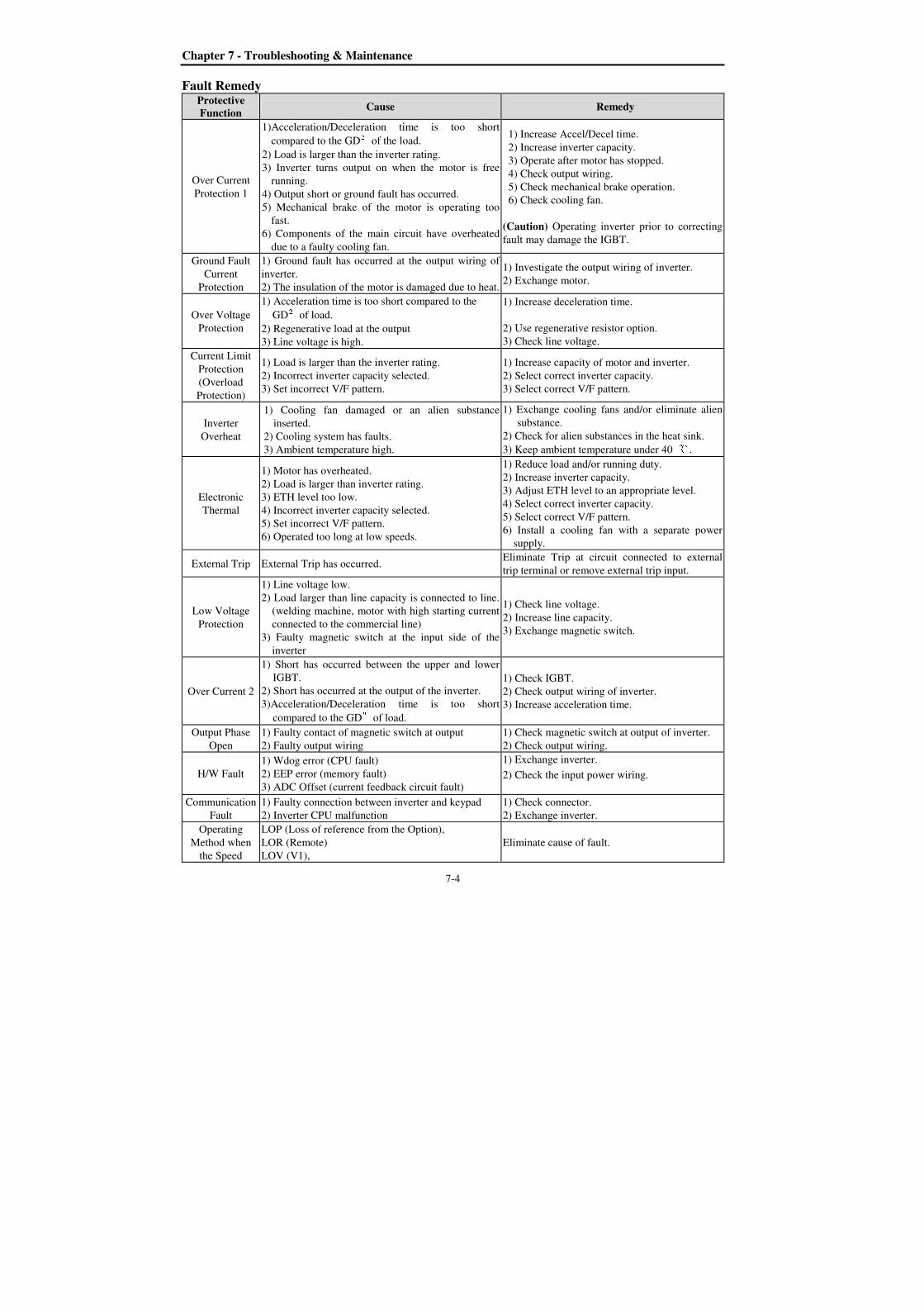
Chapter 7 - Troubleshooting & Maintenance
7-4
Fault Remedy Protective Function
Cause Remedy
Over Current
Protection 1
1)Acceleration/Deceleration time is too short
compared to the GD²of the load.
2) Load is larger than the inverter rating.
3) Inverter turns output on when the motor is free
running.
4) Output short or ground fault has occurred.
5) Mechanical brake of the motor is operating too
fast.
6) Components of the main circuit have overheated
due to a faulty cooling fan.
1) Increase Accel/Decel time.
2) Increase inverter capacity.
3) Operate after motor has stopped.
4) Check output wiring.
5) Check mechanical brake operation.
6) Check cooling fan.
(Caution) Operating inverter prior to correcting
fault may damage the IGBT.
Ground Fault
Current
Protection
1) Ground fault has occurred at the output wiring of
inverter.
2) The insulation of the motor is damaged due to heat.
1) Investigate the output wiring of inverter.
2) Exchange motor.
Over Voltage
Protection
1) Acceleration time is too short compared to the
GD²of load.
2) Regenerative load at the output
3) Line voltage is high.
1) Increase deceleration time.
2) Use regenerative resistor option.
3) Check line voltage.
Current Limit
Protection
(Overload
Protection)
1) Load is larger than the inverter rating.
2) Incorrect inverter capacity selected.
3) Set incorrect V/F pattern.
1) Increase capacity of motor and inverter.
2) Select correct inverter capacity.
3) Select correct V/F pattern.
Inverter
Overheat
1) Cooling fan damaged or an alien substance
inserted.
2) Cooling system has faults.
3) Ambient temperature high.
1) Exchange cooling fans and/or eliminate alien
substance.
2) Check for alien substances in the heat sink.
3) Keep ambient temperature under 40 .
Electronic
Thermal
1) Motor has overheated.
2) Load is larger than inverter rating.
3) ETH level too low.
4) Incorrect inverter capacity selected.
5) Set incorrect V/F pattern.
6) Operated too long at low speeds.
1) Reduce load and/or running duty.
2) Increase inverter capacity.
3) Adjust ETH level to an appropriate level.
4) Select correct inverter capacity.
5) Select correct V/F pattern.
6) Install a cooling fan with a separate power
supply.
External Trip External Trip has occurred. Eliminate Trip at circuit connected to external
trip terminal or remove external trip input.
Low Voltage
Protection
1) Line voltage low.
2) Load larger than line capacity is connected to line.
(welding machine, motor with high starting current
connected to the commercial line)
3) Faulty magnetic switch at the input side of the
inverter
1) Check line voltage.
2) Increase line capacity.
3) Exchange magnetic switch.
Over Current 2
1) Short has occurred between the upper and lower
IGBT.
2) Short has occurred at the output of the inverter.
3)Acceleration/Deceleration time is too short
compared to the GD²of load.
1) Check IGBT.
2) Check output wiring of inverter.
3) Increase acceleration time.
Output Phase
Open
1) Faulty contact of magnetic switch at output
2) Faulty output wiring
1) Check magnetic switch at output of inverter.
2) Check output wiring.
H/W Fault
1) Wdog error (CPU fault)
2) EEP error (memory fault)
3) ADC Offset (current feedback circuit fault)
1) Exchange inverter.
2) Check the input power wiring.
Communication
Fault
1) Faulty connection between inverter and keypad
2) Inverter CPU malfunction
1) Check connector.
2) Exchange inverter.
Operating
Method when
the Speed
LOP (Loss of reference from the Option),
LOR (Remote)
LOV (V1),
Eliminate cause of fault.

Chapter 7 - Troubleshooting & Maintenance
7-5
Protective Function
Cause Remedy
Reference is
Lost
LOI (I),
LOX (Sub-V2, ENC)
Inverter
Overload
1) Load is larger than inverter rating.
2) Incorrect inverter capacity selected.
1) Increase motor and/or inverter capacity.
2) Select correct inverter capacity.

Chapter 7 - Troubleshooting & Maintenance
7-6
7.2 Troubleshooting
Condition Checking Point
The Motor Does Not
Rotate.
1) Main circuit inspection:
- Is the input (line) voltage normal? (Is the LED in the inverter is lit?)
- Is the motor connected correctly?
2) Input signal inspection:
- Check the operating signal input to the inverter.
- Check the forward and the reverse signal input simultaneously to the inverter?
- Check the command frequency signal input to the inverter.
3) Parameter setting inspection:
- Is the reverse prevention (FU1-01) function set?
- Is the Drive mode (DRV-03) set correctly?
- Is the command frequency set to 0?
4) Load inspection:
- Is the load too large or is the motor jammed? (Mechanical brake)
5) Other:
- Is the alarm displayed on the keypad or is the alarm LED lit? (STOP LED
blinks)
The Motor Rotates in
Opposite Directions.
- Is the phase sequence of the output terminal U, V, W correct?
- Is the starting signal (forward/reverse) connected correctly?
The Difference Between
the Rotating Speed and the
Reference is Too Large.
- Is the frequency reference signal correct? (Check the level of the input signal)
- Is the following parameter setting is correct?
- Lower Limit Frequency (FU1-34), Upper Limit Frequency (FU1-35), Analog
Frequency Gain (I/O-1~10)
- Is the input signal line influenced by external noise? (Use a shielded wire)
The Inverter Does Not
Accelerate or Decelerate
Smoothly.
- Is the acceleration/deceleration time is set too short a period of time?
- Is the load too large?
- Is the Torque Boost (FU2-68, 69) value is too high that the current limit
function and the stall prevention function do not operate?
The Motor Current is Too
High.
- Is the load too large?
- Is the Torque Boost Value (manual) too high?
The Rotating Speed Does
Not Increase.
- Is the Upper Limit Frequency (FU1-35) value correct?
- Is the load too large?
- Is the Torque Boost (FU1-68, 69) value too high that the stall prevention
function (FU1-71) does not operate?
The Rotating Speed
Oscillates When the
Inverter is Operating.
1) Load inspection:
- Is the load oscillating?
2) Input signal inspection:
- Is the frequency reference signal oscillating?
3) Other:
- Is the wiring too long when the inverter is using V/F control? (over 500m)

Chapter 7 - Troubleshooting & Maintenance
7-7
7.3 How to Check Power Components
1) Diode module and IGBT module check (5.5~ 30kW)
Before checking the power components, be sure to disconnect AC Input supply and wait until the Main
Electrolytic Capacitors (DCP-DCN) is discharged.
Turn the power off and disconnect RST/UVW wiring.
Determine whether inverter terminals (R,S,T, U, V, W, P1(or P2),N) are energized or not using a tester.
Wait until the Main Electrolytic Capacitors (DCP-DCN) is discharged to a safe level.
Enormous amount of value such as Mega will be displayed when Open. When closed, the resistance
value ranges from a few ohms to tens of Ω. Sometimes, it seems to be closed due to electrolytic
capacitors but soon to be displayed mega value resistance.
The displayed value is not always the same according to modules and tester types but should be similar.
Modules number and checking point
Module Test polarity Check
value Number
Test polarity Check
value + - + -
Diode
D1 R DCP+ Closed
D4 R N Open
DCP+ R Open N R Closed
D2 S DCP+ Closed
D5 S N Open
DCP+ S Open N S Closed
D3 T DCP+ Closed
D6 T N Open
DCP+ T Open N T Closed
IGBT
Tr1 U DCP Closed
Tr4 U N Open
DCP U Open N U Closed
Tr3 V DCP Closed
Tr6 V N Open
DCP V Open N V Closed
Tr5 W DCP Closed
Tr2 W N Open
DCP W Open N W Closed
Charge resistor
M/C
R
S
T
U
V
W
D1
++++ Electrolytic capacitors
N
Tr6
Tr5
Tr2 Tr4
D2 D3
D4 D5 D6

Chapter 7 - Troubleshooting & Maintenance
7-8
2) Diode module and IGBT module check (37~ 90kW)
Turn the power off and disconnect RST/UVW wiring. Determine whether inverter terminals (R,S,T, U, V, W, P1(or P2),N) are energized or not using a tester.
Wait until the Main Electrolytic Capacitors (DCP-DCN) is discharged to a safe level.
Enormous amount of value such as Mega will be displayed when Open. When closed, the resistance
value ranges from a few ohms to tens of Ω. Sometimes, it seems to be closed due to electrolytic
capacitors but soon to be displayed mega value resistance.
The displayed value is not always the same according to modules and tester types but should be similar.
Modules number and checking point
Module Test polarity Check
value Number
Test polarity Check
value + - + -
Diode
D1 R DCP+ Closed
D4 R N Open
DCP+ R Open N R Closed
D5 S N Open
D6 T N Open
N S Closed N T Closed
IGBT
Tr1 U DCP Closed
Tr4 U N Open
DCP U Open N U Closed
Tr3 V DCP Closed
Tr6 V N Open
DCP V Open N V Closed
Tr5 W DCP Closed
Tr2 W N Open
DCP W Open N W Closed
Charge resistor
R
S
T
U
V
W
SCR1 ++++
Electrolytic capacitor
Tr6
Tr5
Tr2 Tr4
SCR2 SCR3
D4 D5 D6
Charge diode
D1
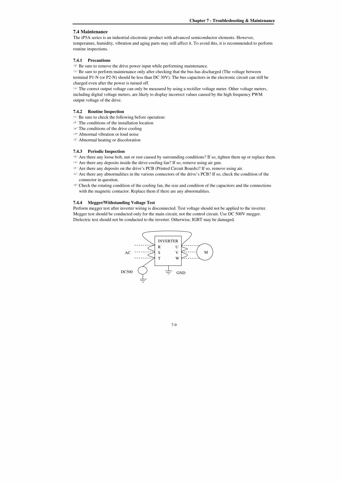
Chapter 7 - Troubleshooting & Maintenance
7-9
7.4 Maintenance The iP5A series is an industrial electronic product with advanced semiconductor elements. However,
temperature, humidity, vibration and aging parts may still affect it. To avoid this, it is recommended to perform
routine inspections.
7.4.1 Precautions Be sure to remove the drive power input while performing maintenance. Be sure to perform maintenance only after checking that the bus has discharged (The voltage between
terminal P1-N (or P2-N) should be less than DC 30V). The bus capacitors in the electronic circuit can still be
charged even after the power is turned off. The correct output voltage can only be measured by using a rectifier voltage meter. Other voltage meters,
including digital voltage meters, are likely to display incorrect values caused by the high frequency PWM
output voltage of the drive.
7.4.2 Routine Inspection Be sure to check the following before operation: The conditions of the installation location The conditions of the drive cooling Abnormal vibration or loud noise Abnormal heating or discoloration
7.4.3 Periodic Inspection Are there any loose bolt, nut or rust caused by surrounding conditions? If so, tighten them up or replace them. Are there any deposits inside the drive-cooling fan? If so, remove using air gun. Are there any deposits on the drive’s PCB (Printed Circuit Boards)? If so, remove using air. Are there any abnormalities in the various connectors of the drive’s PCB? If so, check the condition of the
connector in question. Check the rotating condition of the cooling fan, the size and condition of the capacitors and the connections
with the magnetic contactor. Replace them if there are any abnormalities.
7.4.4 Megger/Withstanding Voltage Test
Perform megger test after inverter wiring is disconnected. Test voltage should not be applied to the inverter.
Megger test should be conducted only for the main circuit, not the control circuit. Use DC 500V megger.
Dielectric test should not be conducted to the inverter. Otherwise, IGBT may be damaged.
U
V
W
R
S
T AC
GND DC500
M
INVERTER

Chapter 7 - Troubleshooting & Maintenance
7-10
7.4.5 Daily and Periodic Inspection Items
Insp
ecti
on
L
oca
tio
n
Insp
ecti
on
It
em
Inspection
Period
Inspection Method Criterion Measuring Instrument
Da
ily
1 y
ear
2 y
ear
All
Ambient
Environ-
ment
Is there any dust?
Is the ambient temperature and
humidity adequate? Ο
Refer to the precautions. Temperature:
-10~+40 no
freezing.
Humidity: Under
50% no dew
Thermometer,
Hygrometer,
Recorder
Equipment Is there any abnormal oscillation or
noise? Ο
Use sight and hearing. No abnormality
Input
Voltage
Is the input voltage of the main circuit
normal? Ο
Measure the voltage between the
terminals R, S, T.
Digital Multi-
Meter/Tester
Mai
n C
ircu
it
All
1) Megger check (between the main
circuit and the ground)
2) Are any fixed parts removed?
3) Are there any traces of overheating
at each component’s cleaning?
Ο
Ο
Ο
Ο
1) Undo the inverter connections
short the terminals R, S, T, U, V,
W and measure between these
parts and the ground.
2) Tighten the screws.
3) Visual check.
1) Over 5MΩ
2), 3) No fault
DC 500V class
Megger
Conductor/
Wire
1) Is the conductor rusty?
2) Is the wire coating damaged?
Ο
Ο
Visual check No fault
Terminal Is there any damage? Ο Visual check No fault
IGBT
Module
/Diode
Module
Check the resistance between each of
the terminals.
Ο Undo the inverter connection and
measure the resistance between R,
S, T ⇔ P, N and U, V, W ⇔ P,
N with a tester.
(Refer ‘How to
Check Power
Components”)
Digital Multi-
Meter/Analog
Tester
Smoothing
Capacitor
1) Is there any liquid coming out?
2) Is the safety pin out, and is there
any swelling?
3) Measure the capacitance.
Ο
Ο
Ο
1), 2) Visual check
3) Measure with a capacitance-
measuring device.
1), 2) No fault
3) Over 85% of
the rated capacity
Capacitance
Measuring
Device
Relay
1) Is there any chattering noise during
operation?
2) Is there any damage to the contact
Ο
Ο
1) Auditory check
2) Visual check
No fault
Resistor
1) Is there any damage to the resistor
insulation?
2) Is the wiring in the resistor
damaged (open)?
Ο
Ο
1) Visual check
2) Disconnect one of the
connections and measure with a
tester.
1) No fault
2) Error must be
within ±10%
the displayed
resistance.
Digital Multi-
Meter/Analog
Tester
Con
tro
l C
ircu
it
Pro
tect
ive
Cir
cuit
Operation
Check
1) Is there any unbalance between
each phases of the output voltage?
2) Nothing must be wrong with
display circuit after executing the
sequence protective operation.
Ο
Ο
1) Measure the voltage between
the output terminals U, V and W.
2) Short and open the inverter
protective circuit output.
1) The voltage
balance between
the phases for
200V (400V)
class is under 4V
(8V).
2) The fault
circuit operates
according to the
sequence.
Digital Multi-
Meter/Rectifyin
g Voltmeter
Coo
li
ng
Sy
ste
m Cooling
Fan
1) Is there any abnormal oscillation or
noise?
2) Is the connection area loose?
Ο
Ο
1) Turn OFF the power and turn
the fan by hand.
2) Tighten the connections.
1) Must rotate
smoothly.
2) No fault
Dis
pla
y
Meter
Is the displayed value correct? Ο Ο Check the meter reading at the
exterior of the panel.
Check the
specified and
management
values.
Voltmeter/
Ammeter etc.
Moto
r All
1) Are there any abnormal vibrations
or noise?
2) Is there any unusual odor?
Ο
Ο
1) Auditory, sensory, visual check.
2) Check for overheat and
damage.
No fault
Insulation
Resistor
Megger check (between the output
terminals and the ground terminal)
Ο Undo the U, V and W connections
and tie the motor wiring. Over 5MΩ 500V class
Megger
Note: Values in ( ) is for the 400V class inverters. Note: Life cycle of the Main components indicated above is based on continuous operation with rated load. It may vary with surrounded environment.

Chapter 7 - Troubleshooting & Maintenance
7-11
7.4.6 Parts replacement
Part name Period Comments
Cooling fan 2-3 years Exchange for a new part after consulting
LS A/S center.
Electrolytic
capacitor 5 years
Check for the periodic inspection for 1
year. Exchange for a new part after
consulting LS A/S center.
The Recommended level to exchange a
capacitor in main/control circuit is 85%
or less of the initial value.
Relays - Exchange for a new part after consulting
LS A/S center.
The life expectancy of a part depends on the type of part, the environment, and operating conditions.


8-1
CHAPTER 8 - OPTIONS
8.1 Option List
iP5A series is available to connect below option device.
Ex
tern
al
Keypad LCD 32 character display
keypad Download and Upload available All units
Remote Remote cable
2m, 3m and 5m long keypad cable enables
users to control the inverter from a distant
area.
Optional
Dynamic
braking
DB resistor
To enhance the regenerative braking
performance, it makes the inverter to
accelerate/decelerate rapidly.
According
to inverter
capacity DB unit
If it need a regenerative braking, it is used
with DB resistor.
Conduit option Conduit for
NEMA TYPE 1
Install it to fit for NEMA TYPE 1
Enclosure or IP20.
15~90kW
(20~125HP)
Note) Refer to Option manuals for details.

Chapter 8 - Options
8-2
8.2 External options
8.2.1 Keypad dimensions
1) LCD Keypad (Weight: 140 g)
Chapter 8 - Options
8-3
8.2.2 Remote cable
Ordering No. Description
051050025 Remote cable – 2m
051050026 Remote cable – 3m
051050027 Remote cable – 5m
8.2.3 DB (Dynamic Braking) Unit
Refer to DB Unit option manual for details.
1) DBU Models
UL Inverter Applicable motor rating DB Unit Dimension
Non UL type
200V class
11 ~ 15 kW (15 ~ 20 HP) SV150DBU-2 Group 1. See 4) Dimensions 18.5 ~ 22 Kw (25 ~ 30 HP) SV220DBU-2
30 ~ 37 kW (40 ~ 50 HP) SV037DBH-2 Group 2. See 4) Dimensions 45 ~ 55 kW (60 ~ 75 HP) SV037DBH-2, 2Set
400V class
11 ~ 15 kW (15 ~ 20 HP) SV150DBU-4 Group 1. See 4) Dimensions 18.5 ~ 22 kW (25 ~ 30 HP) SV220DBU-4
30 ~ 37 kW (40 ~ 50 HP) SV037DBH-4 Group 2.
See 4) Dimensions 45 ~ 55 kW (60 ~ 75 HP)
SV075DBH-4 75 kW (100 HP)
UL Type
200V class
11 ~ 15 kW (15 ~ 20 HP) SV150DBU-2U
Group 3. See 4) Dimensions
18.5 ~ 22 kW (25 ~ 30 HP) SV220DBU-2 U 30 ~ 37 kW (40 ~ 50 HP) SV370DBU-2 U 45 ~ 55 kW (60 ~ 75 HP) SV550DBU-2 U
400V class
11 ~ 15 kW (15 ~ 20 HP) SV150DBU-4 U 18.5 ~ 22 kW (25 ~ 30 HP) SV220DBU-4 U
30 ~ 37 kW (40 ~ 50 HP) SV370DBU-4 U
45 ~ 55 kW (60 ~ 75 HP) SV550DBU-4 U 75 kW (100 HP) SV750DBU-4 U 90~110 kW (125 ~ 150 HP) SV550DBU-4, 2Set 132~160 kW (200 ~ 250 HP) SV750DBU-4, 2Set 220 kW (300 HP) SV750DBU-4, 3Set 280~315 kW (350 ~ 400 HP) -
375~450 kW (500 ~ 600 HP) -
2) Terminal Configuration
- Group 1:
- Group 2:
- Group 3:
Terminals Description Terminals Description
G Ground terminal N Connect to inverter terminal N
B2 Connect to DB Resistor’s B2 P Connect to inverter terminal P1
B1 Connect to DB Resistor’s B1 CM OH Common
N Connect to inverter terminal N OH*
Over Heat Trip output terminal (Open Collector output: 20mA, 27V DC) P Connect to inverter terminal P1 Caution) Refer to Dynamic Braking Unit manuals for details.
3) Wiring for DB unit and DB resistor (for 5.5~90kW/7.5~125HP inverters)
N B2 P/B1 G
B2 B1 N P G
B2 B1 N P OH G CM
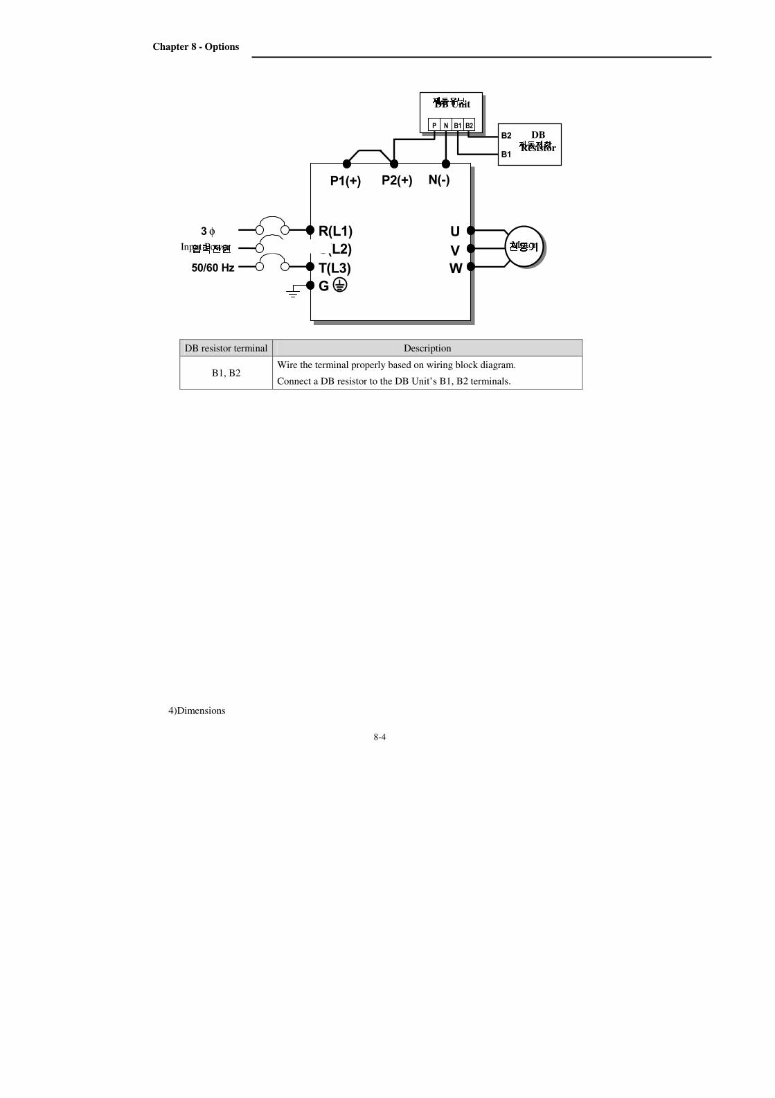
Chapter 8 - Options
8-4
4)Dimensions
입력전원입력전원입력전원입력전원 50/60 Hz
U
V
W
G
R(L1)
S(L2)
T(L3)
φ 3 전동기전동기전동기전동기 P2(+)
P1(+)
P N B1 B2 N(-)
B2
B1 제동저항제동저항제동저항제동저항
제동유닛제동유닛제동유닛제동유닛
DB resistor terminal Description
B1, B2 Wire the terminal properly based on wiring block diagram.
Connect a DB resistor to the DB Unit’s B1, B2 terminals.
Motor
DB
Resistor
DB Unit
Input Power
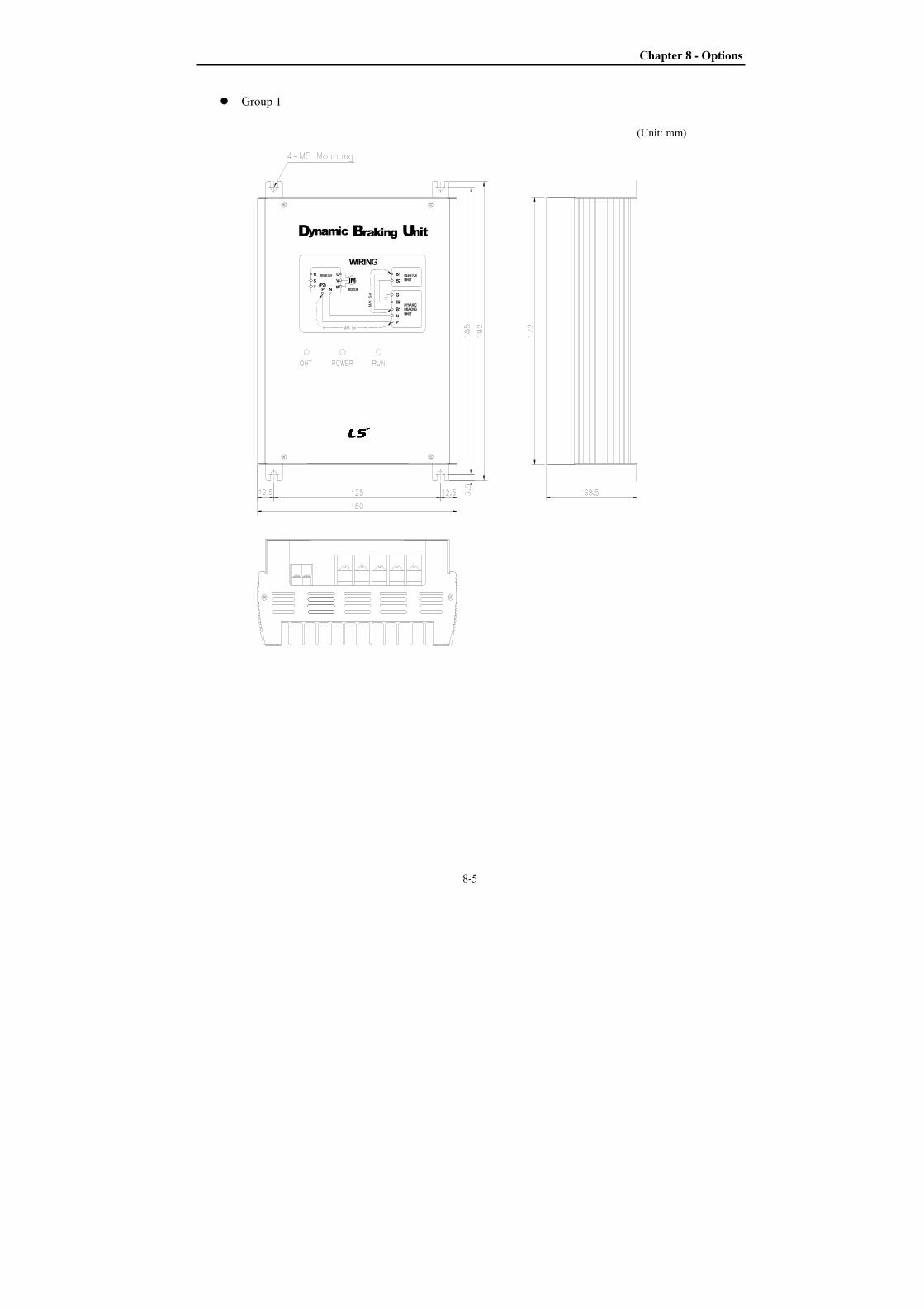
Chapter 8 - Options
8-5
Group 1
(Unit: mm)
N
ynamic
TP
D
R
S(P2)
W
N
P
B2
B1
G
rakingB
WIRING
V
U
IM
nitU
B2
B1
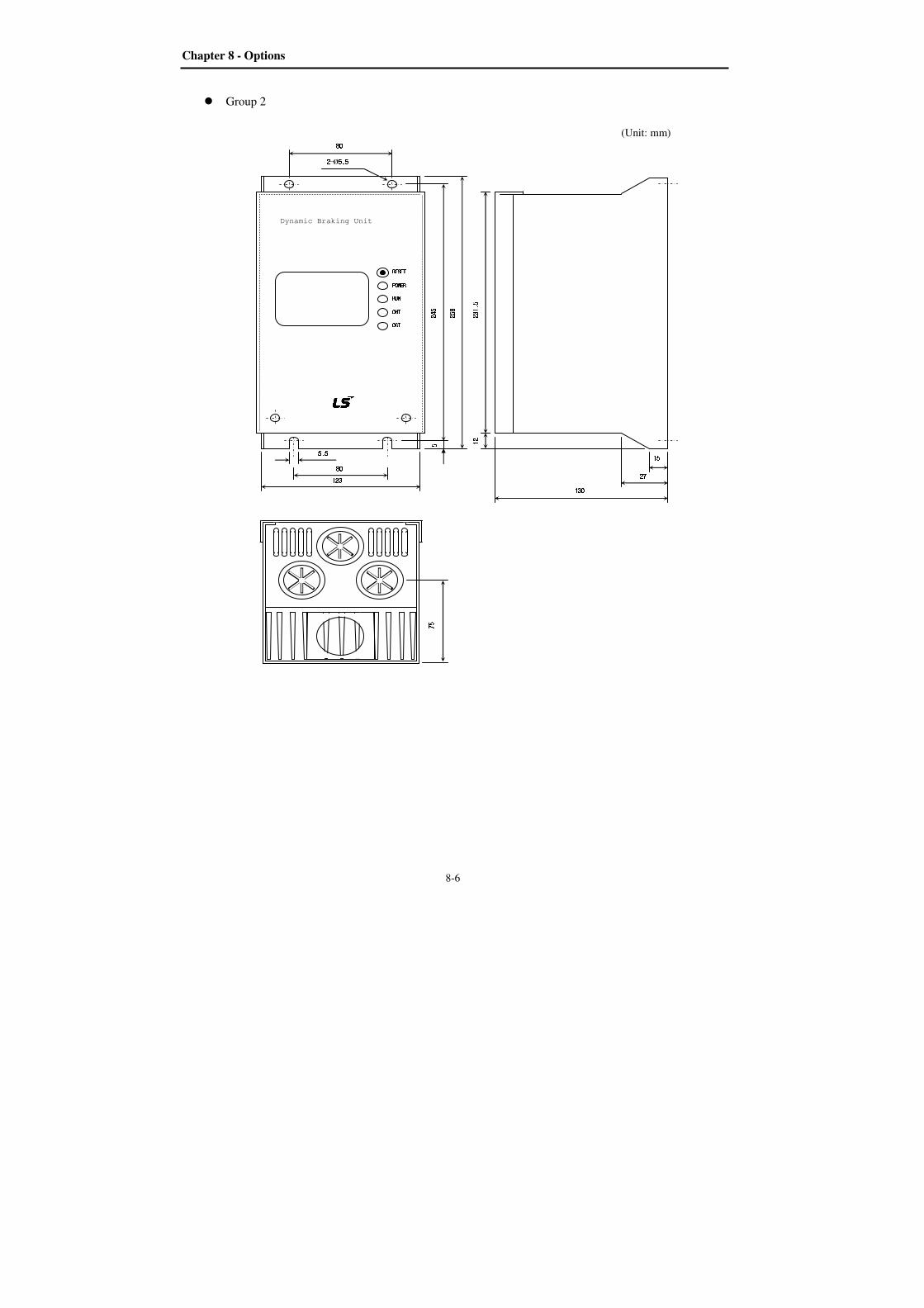
Chapter 8 - Options
8-6
Group 2
(Unit: mm)
5.55.55.55.5 258258258258
5555 245245245245
2222----Ø5.55.55.55.5
80808080
80808080
123123123123
Dynamic Braking Unit RESETRESETRESETRESET POWERPOWERPOWERPOWER RUNRUNRUNRUN OHTOHTOHTOHT OCTOCTOCTOCT 231.5231.5231.5231.5 12121212 15151515 27272727 130130130130
75757575
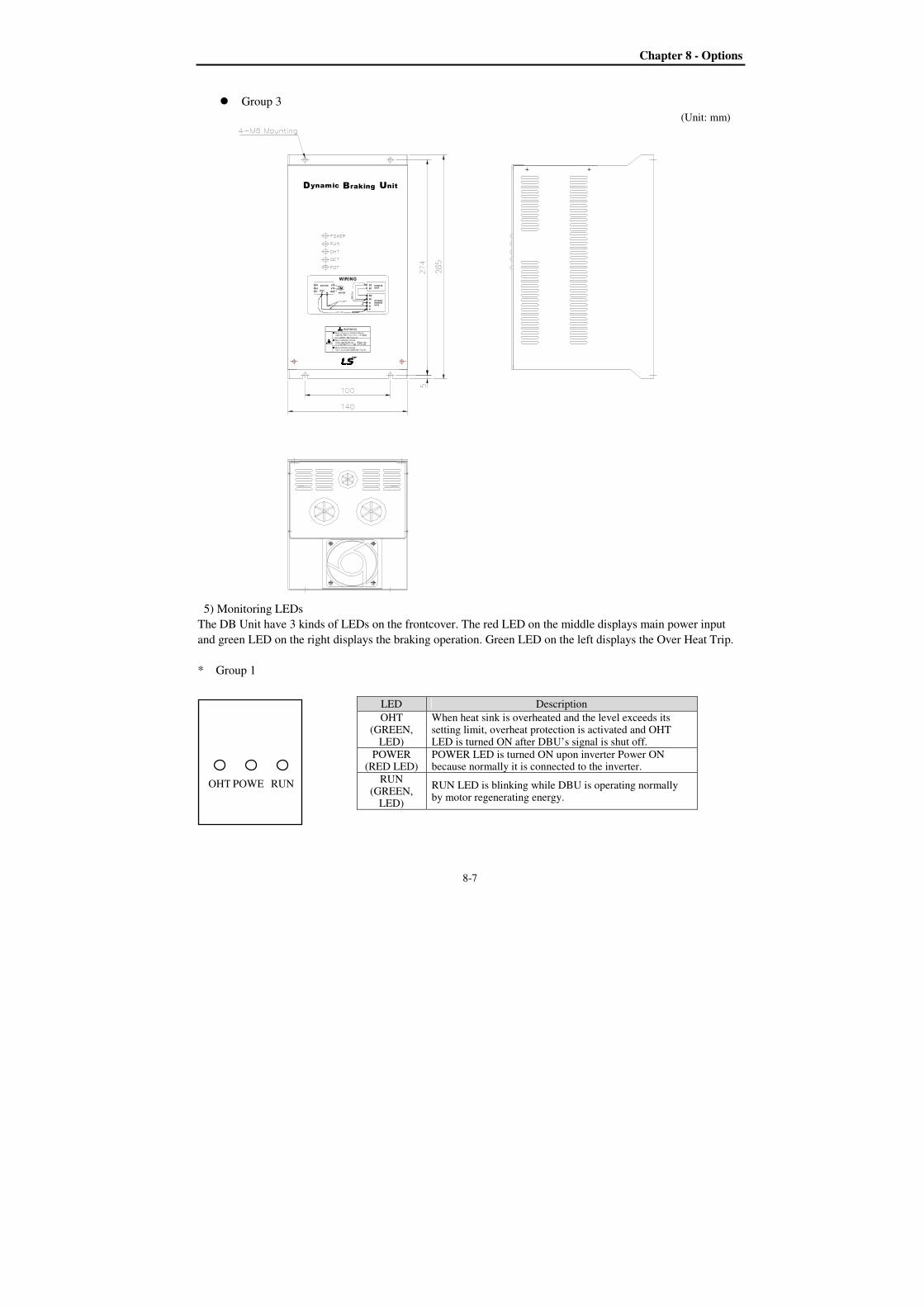
Chapter 8 - Options
8-7
Group 3
(Unit: mm)
5) Monitoring LEDs
The DB Unit have 3 kinds of LEDs on the frontcover. The red LED on the middle displays main power input
and green LED on the right displays the braking operation. Green LED on the left displays the Over Heat Trip.
* Group 1
LED Description
OHT (GREEN,
LED)
When heat sink is overheated and the level exceeds its setting limit, overheat protection is activated and OHT LED is turned ON after DBU’s signal is shut off.
POWER (RED LED)
POWER LED is turned ON upon inverter Power ON because normally it is connected to the inverter.
RUN (GREEN,
LED)
RUN LED is blinking while DBU is operating normally by motor regenerating energy. OHT POWE RUN
Risk of Electric Shock
Risk of Electric Shock
Risk of Injury or Electric Shock
IM
ynamic
R
T
S
U
NP(P2)
W
V
D
B1
WARNING
N
P
G
WIRING
B2
B2
B1
UrakingB nit
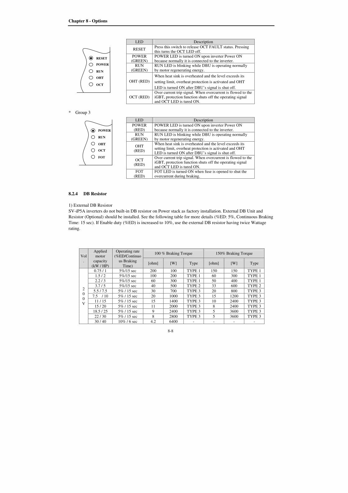
Chapter 8 - Options
8-8
* Group 3
8.2.4 DB Resistor
1) External DB Resistor
SV-iP5A inverters do not built-in DB resistor on Power stack as factory installation. External DB Unit and
Resistor (Optional) should be installed. See the following table for more details (%ED: 5%, Continuous Braking
Time: 15 sec). If Enable duty (%ED) is increased to 10%, use the external DB resistor having twice Wattage
rating.
Vol
.
Applied
motor
capacity
(kW / HP)
Operating rate
(%ED/Continuo
us Braking
Time)
100 % Braking Torque 150% Braking Torque
[ohm] [W] Type [ohm] [W] Type
2
0
0
V
0.75 / 1 5%/15 sec 200 100 TYPE 1 150 150 TYPE 1
1.5 / 2 5%/15 sec 100 200 TYPE 1 60 300 TYPE 1
2.2 / 3 5%/15 sec 60 300 TYPE 1 50 400 TYPE 1
3.7 / 5 5%/15 sec 40 500 TYPE 2 33 600 TYPE 2
5.5 / 7.5 5% / 15 sec 30 700 TYPE 3 20 800 TYPE 3
7.5 / 10 5% / 15 sec 20 1000 TYPE 3 15 1200 TYPE 3
11 / 15 5% / 15 sec 15 1400 TYPE 3 10 2400 TYPE 3
15 / 20 5% / 15 sec 11 2000 TYPE 3 8 2400 TYPE 3
18.5 / 25 5% / 15 sec 9 2400 TYPE 3 5 3600 TYPE 3
22 / 30 5% / 15 sec 8 2800 TYPE 3 5 3600 TYPE 3
30 / 40 10% / 6 sec 4.2 6400 - - - -
RESET
POWER
RUN
OHT
OCT
LED Description
RESET Press this switch to release OCT FAULT status. Pressing this turns the OCT LED off.
POWER (GREEN)
POWER LED is turned ON upon inverter Power ON because normally it is connected to the inverter.
RUN (GREEN)
RUN LED is blinking while DBU is operating normally by motor regenerating energy.
OHT (RED)
When heat sink is overheated and the level exceeds its
setting limit, overheat protection is activated and OHT
LED is turned ON after DBU’s signal is shut off.
OCT (RED) Over current trip signal. When overcurrent is flowed to the iGBT, protection function shuts off the operating signal and OCT LED is tured ON.
POWER
RUN
OHT
OCT
FOT
LED Description
POWER (RED)
POWER LED is turned ON upon inverter Power ON because normally it is connected to the inverter.
RUN (GREEN)
RUN LED is blinking while DBU is operating normally by motor regenerating energy.
OHT (RED)
When heat sink is overheated and the level exceeds its setting limit, overheat protection is activated and OHT LED is turned ON after DBU’s signal is shut off.
OCT (RED)
Over current trip signal. When overcurrent is flowed to the iGBT, protection function shuts off the operating signal and OCT LED is tured ON.
FOT (RED)
FOT LED is turned ON when fuse is opened to shut the overcurrent during braking.
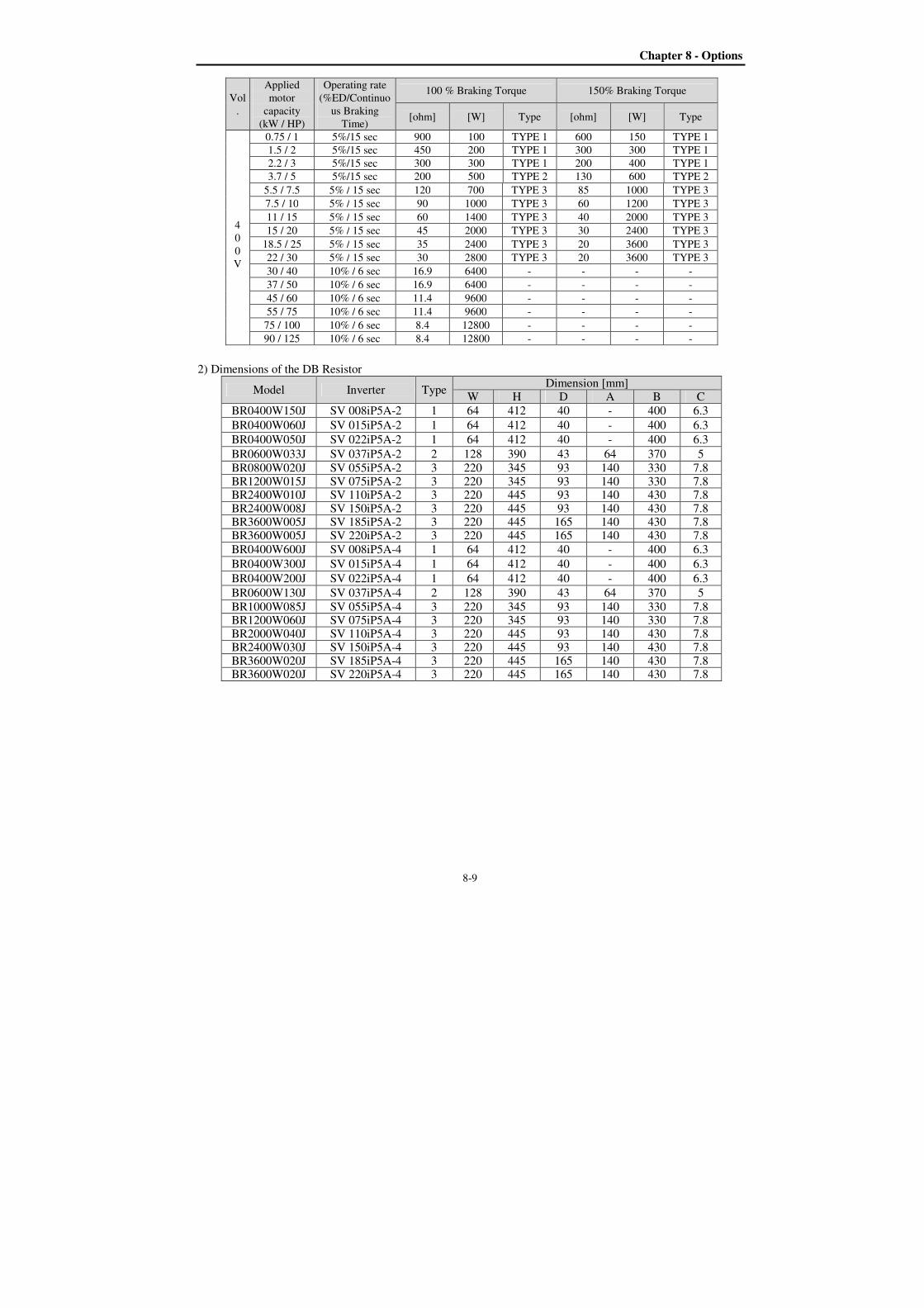
Chapter 8 - Options
8-9
Vol
.
Applied
motor
capacity
(kW / HP)
Operating rate
(%ED/Continuo
us Braking
Time)
100 % Braking Torque 150% Braking Torque
[ohm] [W] Type [ohm] [W] Type
4
0
0
V
0.75 / 1 5%/15 sec 900 100 TYPE 1 600 150 TYPE 1
1.5 / 2 5%/15 sec 450 200 TYPE 1 300 300 TYPE 1
2.2 / 3 5%/15 sec 300 300 TYPE 1 200 400 TYPE 1
3.7 / 5 5%/15 sec 200 500 TYPE 2 130 600 TYPE 2
5.5 / 7.5 5% / 15 sec 120 700 TYPE 3 85 1000 TYPE 3
7.5 / 10 5% / 15 sec 90 1000 TYPE 3 60 1200 TYPE 3
11 / 15 5% / 15 sec 60 1400 TYPE 3 40 2000 TYPE 3
15 / 20 5% / 15 sec 45 2000 TYPE 3 30 2400 TYPE 3
18.5 / 25 5% / 15 sec 35 2400 TYPE 3 20 3600 TYPE 3
22 / 30 5% / 15 sec 30 2800 TYPE 3 20 3600 TYPE 3
30 / 40 10% / 6 sec 16.9 6400 - - - -
37 / 50 10% / 6 sec 16.9 6400 - - - -
45 / 60 10% / 6 sec 11.4 9600 - - - -
55 / 75 10% / 6 sec 11.4 9600 - - - -
75 / 100 10% / 6 sec 8.4 12800 - - - -
90 / 125 10% / 6 sec 8.4 12800 - - - -
2) Dimensions of the DB Resistor
Model Inverter Type Dimension [mm]
W H D A B C
BR0400W150J SV 008iP5A-2 1 64 412 40 - 400 6.3
BR0400W060J SV 015iP5A-2 1 64 412 40 - 400 6.3
BR0400W050J SV 022iP5A-2 1 64 412 40 - 400 6.3
BR0600W033J SV 037iP5A-2 2 128 390 43 64 370 5
BR0800W020J SV 055iP5A-2 3 220 345 93 140 330 7.8 BR1200W015J SV 075iP5A-2 3 220 345 93 140 330 7.8 BR2400W010J SV 110iP5A-2 3 220 445 93 140 430 7.8 BR2400W008J SV 150iP5A-2 3 220 445 93 140 430 7.8 BR3600W005J SV 185iP5A-2 3 220 445 165 140 430 7.8 BR3600W005J SV 220iP5A-2 3 220 445 165 140 430 7.8
BR0400W600J SV 008iP5A-4 1 64 412 40 - 400 6.3
BR0400W300J SV 015iP5A-4 1 64 412 40 - 400 6.3
BR0400W200J SV 022iP5A-4 1 64 412 40 - 400 6.3
BR0600W130J SV 037iP5A-4 2 128 390 43 64 370 5
BR1000W085J SV 055iP5A-4 3 220 345 93 140 330 7.8 BR1200W060J SV 075iP5A-4 3 220 345 93 140 330 7.8 BR2000W040J SV 110iP5A-4 3 220 445 93 140 430 7.8 BR2400W030J SV 150iP5A-4 3 220 445 93 140 430 7.8 BR3600W020J SV 185iP5A-4 3 220 445 165 140 430 7.8 BR3600W020J SV 220iP5A-4 3 220 445 165 140 430 7.8
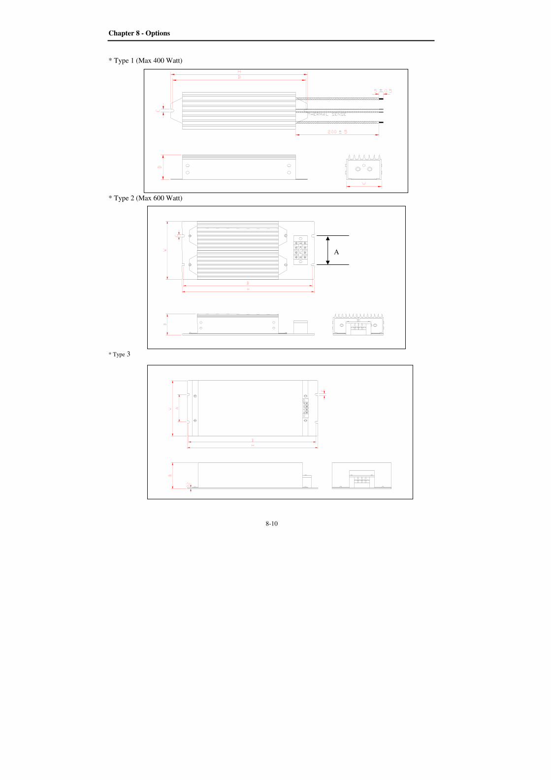
Chapter 8 - Options
8-10
* Type 1 (Max 400 Watt)
* Type 2 (Max 600 Watt)
* Type 3
A
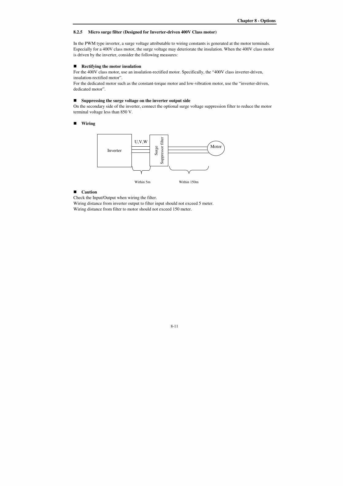
Chapter 8 - Options
8-11
8.2.5 Micro surge filter (Designed for Inverter-driven 400V Class motor)
In the PWM type inverter, a surge voltage attributable to wiring constants is generated at the motor terminals.
Especially for a 400V class motor, the surge voltage may deteriorate the insulation. When the 400V class motor
is driven by the inverter, consider the following measures:
Rectifying the motor insulation
For the 400V class motor, use an insulation-rectified motor. Specifically, the “400V class inverter-driven,
insulation-rectified motor”.
For the dedicated motor such as the constant-torque motor and low-vibration motor, use the “inverter-driven,
dedicated motor”.
Suppressing the surge voltage on the inverter output side
On the secondary side of the inverter, connect the optional surge voltage suppression filter to reduce the motor
terminal voltage less than 850 V.
Wiring
Caution
Check the Input/Output when wiring the filter.
Wiring distance from inverter output to filter input should not exceed 5 meter.
Wiring distance from filter to motor should not exceed 150 meter.
Motor U,V,W
Inverter
Within 5m Within 150m
Su
rge
Su
pp
ress
or
filt
er
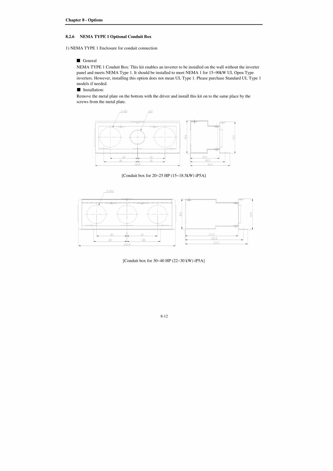
Chapter 8 - Options
8-12
8.2.6 NEMA TYPE 1 Optional Conduit Box
1) NEMA TYPE 1 Enclosure for conduit connection
General
NEMA TYPE 1 Conduit Box: This kit enables an inverter to be installed on the wall without the inverter
panel and meets NEMA Type 1. It should be installed to meet NEMA 1 for 15~90kW UL Open Type
inverters. However, installing this option does not mean UL Type 1. Please purchase Standard UL Type 1
models if needed. Installation:
Remove the metal plate on the bottom with the driver and install this kit on to the same place by the
screws from the metal plate.
[Conduit box for 20~25 HP (15~18.5kW) iP5A]
[Conduit box for 30~40 HP (22~30 kW) iP5A]
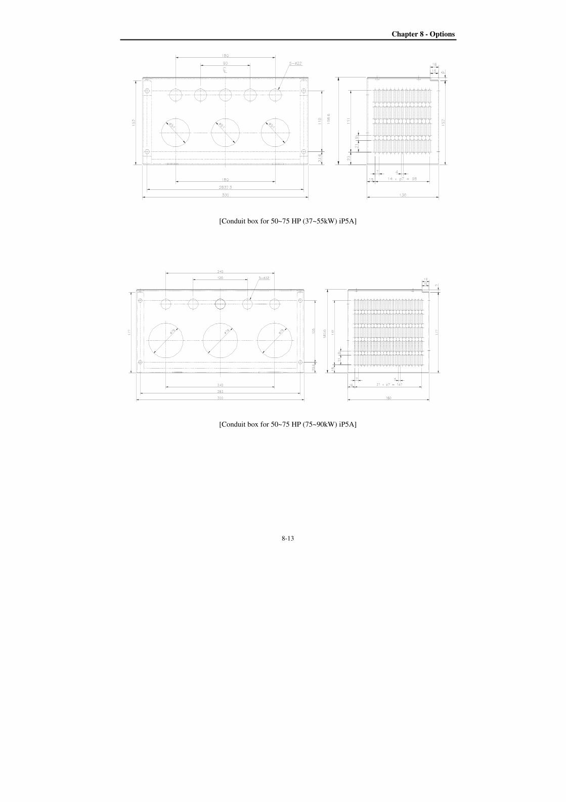
Chapter 8 - Options
8-13
[Conduit box for 50~75 HP (37~55kW) iP5A]
[Conduit box for 50~75 HP (75~90kW) iP5A]
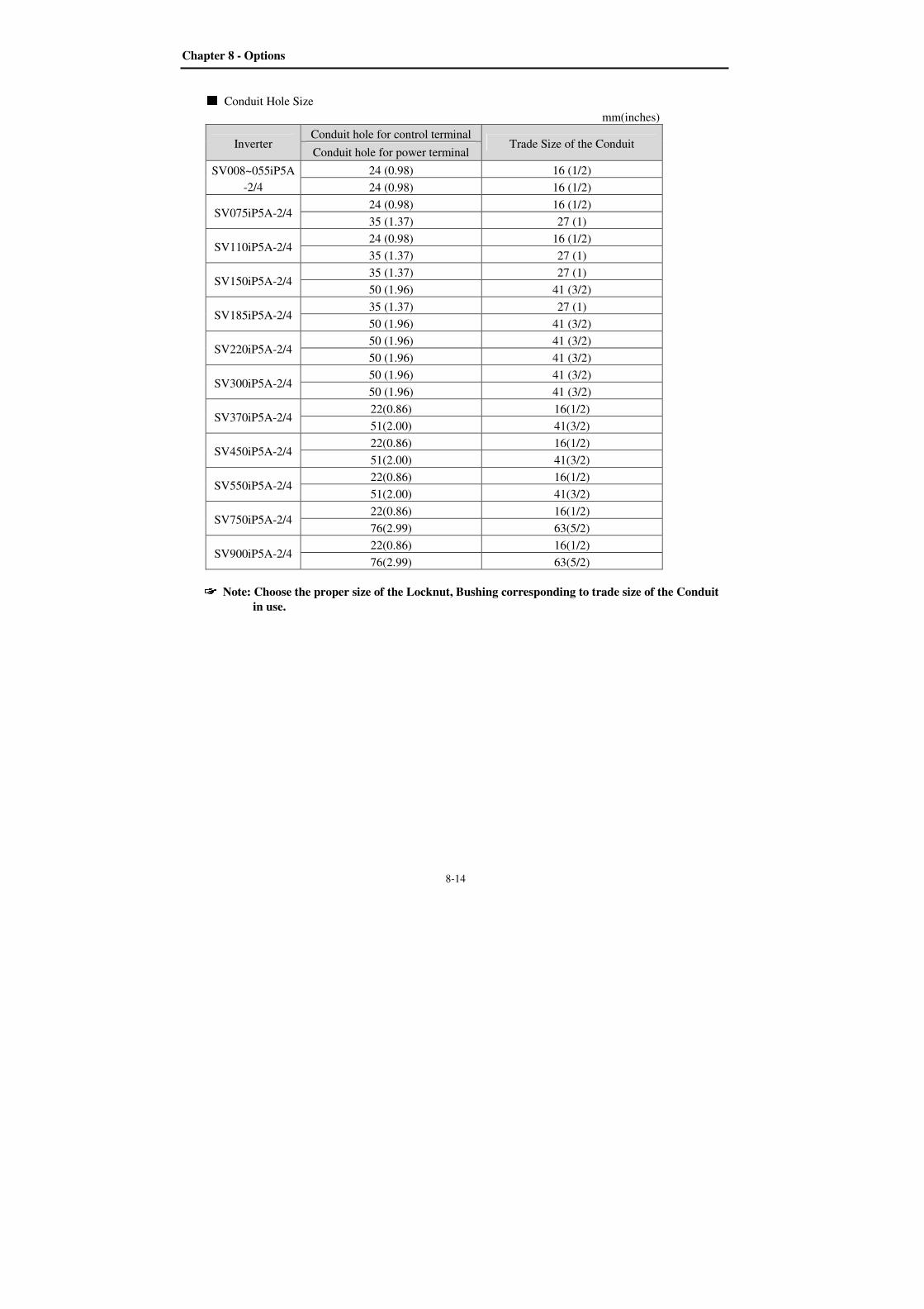
Chapter 8 - Options
8-14
Conduit Hole Size
mm(inches)
Inverter Conduit hole for control terminal
Trade Size of the Conduit Conduit hole for power terminal
SV008~055iP5A
-2/4
24 (0.98) 16 (1/2)
24 (0.98) 16 (1/2)
SV075iP5A-2/4 24 (0.98) 16 (1/2)
35 (1.37) 27 (1)
SV110iP5A-2/4 24 (0.98) 16 (1/2)
35 (1.37) 27 (1)
SV150iP5A-2/4 35 (1.37) 27 (1)
50 (1.96) 41 (3/2)
SV185iP5A-2/4 35 (1.37) 27 (1)
50 (1.96) 41 (3/2)
SV220iP5A-2/4 50 (1.96) 41 (3/2)
50 (1.96) 41 (3/2)
SV300iP5A-2/4 50 (1.96) 41 (3/2)
50 (1.96) 41 (3/2)
SV370iP5A-2/4 22(0.86) 16(1/2)
51(2.00) 41(3/2)
SV450iP5A-2/4 22(0.86) 16(1/2)
51(2.00) 41(3/2)
SV550iP5A-2/4 22(0.86) 16(1/2)
51(2.00) 41(3/2)
SV750iP5A-2/4 22(0.86) 16(1/2)
76(2.99) 63(5/2)
SV900iP5A-2/4 22(0.86) 16(1/2)
76(2.99) 63(5/2)
Note: Choose the proper size of the Locknut, Bushing corresponding to trade size of the Conduit
in use.
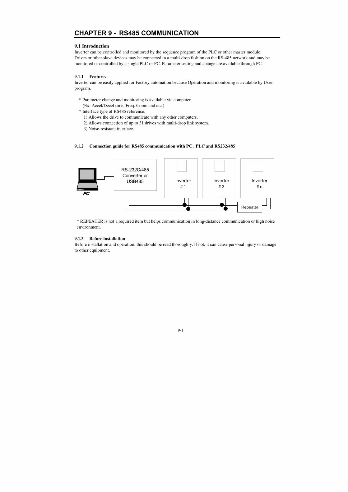
9-1
CHAPTER 9 - RS485 COMMUNICATION
9.1 Introduction Inverter can be controlled and monitored by the sequence program of the PLC or other master module.
Drives or other slave devices may be connected in a multi-drop fashion on the RS-485 network and may be
monitored or controlled by a single PLC or PC. Parameter setting and change are available through PC.
9.1.1 Features
Inverter can be easily applied for Factory automation because Operation and monitoring is available by User-
program.
* Parameter change and monitoring is available via computer.
(Ex: Accel/Decel time, Freq. Command etc.)
* Interface type of RS485 reference:
1) Allows the drive to communicate with any other computers.
2) Allows connection of up to 31 drives with multi-drop link system.
3) Noise-resistant interface.
9.1.2 Connection guide for RS485 communication with PC , PLC and RS232/485
* REPEATER is not a required item but helps communication in long-distance communication or high noise
environment.
9.1.3 Before installation
Before installation and operation, this should be read thoroughly. If not, it can cause personal injury or damage
to other equipment.
PCPCPCPC
Inverter
# 1
Inverter
# 2
Inverter
# n
RS-232C/485 Converter or USB485
Repeater
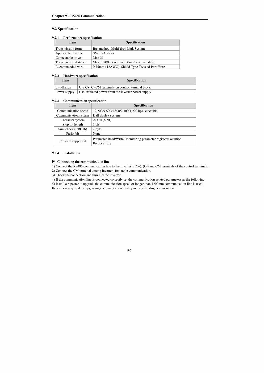
Chapter 9 – RS485 Communication
9-2
9.2 Specification
9.2.1 Performance specification
Item Specification
Transmission form Bus method, Multi-drop Link System
Applicable inverter SV-iP5A series
Connectable drives Max 31
Transmission distance Max. 1,200m (Within 700m Recommended)
Recommended wire 0.75mm2(12AWG), Shield Type Twisted-Pare Wire
9.2.2 Hardware specification
Item Specification
Installation Use C+, C-,CM terminals on control terminal block
Power supply Use Insulated power from the inverter power supply
9.2.3 Communication specification
Item Specification
Communication speed 19,200/9,600/4,800/2,400/1,200 bps selectable
Communication system Half duplex system
Character system ASCII (8 bit)
Stop bit length 1 bit
Sum check (CRC16) 2 byte
Parity bit None
Protocol supported Parameter Read/Write, Monitoring parameter register/execution
Broadcasting
9.2.4 Installation
Connecting the communication line
1) Connect the RS485 communication line to the inverter’s (C+), (C-) and CM terminals of the control terminals.
2) Connect the CM terminal among inverters for stable communication.
3) Check the connection and turn ON the inverter.
4) If the communication line is connected correctly set the communication-related parameters as the following.
5) Install a repeater to upgrade the communication speed or longer than 1200mm communication line is used.
Repeater is required for upgrading communication quality in the noise-high environment.
Chapter 9 – RS485 Communication
9-3
Communication parameters
Code Display Name Set value Unit Default
DRV_03 Drive mode Drive mode Int. 485 Fx/Rx-1
DRV_04 Freq mode Freq mode Int. 485 KeyPad-1
DRV_91 Drive mode2 Drive mode 2
KeyPad
Fx/Rx-1
Fx/Rx-2
Fx/Rx-1
DRV_92 Freq mode2 Freq mode 2
KeyPad-1
KeyPad-2
V1
V1S
I
V1+I
Pulse
KeyPad-1
I/O_20~27 M1 ~ M8 Programmable
Digital Inputs Main-drive
I/O_90 Inv No Inverter number 1~250 1
I/O_91 Baud rate Communication
speed
1200 bps
2400 bps
4800 bps
9600 bps
19200 bps
9600 bps
I/O_92 COM Lost Cmd
Operating mode
when
communication
signal is lost
None
FreeRun
Stop
None
I/O_93 COM Time Out
Time to
determine
whether
Communication
signal is lost.
0.1~120.0 sec 1.0
I/O_94 Delay Time
Delay time of
communication
response
1 ~ 1200 msec 5
9.3 Operation
9.3.1 Operating steps
1) Check whether the computer and the inverter are connected correctly.
2) Turn ON the inverter. But, do not connect the load until stable communication between the computer and the
inverter is verified. Start the operating program for the inverter from the computer.
3) If computer is a master, computer does not have RS485 port. RS232-485 converter is needed to communicate.
The communication is delayed at transmitting/receiving when the RS232-485 converter is used. If delay is
happened, retry the communication by increasing the I/O-94 [Delay Time].
4) Operate the inverter using the operating program for the inverter.
5) Refer to “13.8 Troubleshooting” if the communication is not operating normally.
6) User program or the “DriveView” program supplied from LSIS can be used as the operating program for the
inverter.
7) Turn the inverter J3 switch ON to connect the terminating resistor for the end of network.

Chapter 9 – RS485 Communication
9-4
* Connect to C+,C-,CM terminal on the control terminal. Be careful for the polarity(+, -).
* Max connectable inverter is 31.
9.4 Communication protocol (RS485) The configuration of RS485 is that PC or PLC is the Master and Inverter Slave.
Inverter responds the Master’s Read/Write Requests.
When master sends Write Request to Inverter address # 255, all inverters perform Write action but do not return
a Acknowledge response. This is used to drive multiple inverters at the same time via RS485.
9.4.1 Basic format
1) Command message (Request):
ENQ Inverter No. CMD Data SUM EOT
1 byte 2 bytes 1 byte n bytes 2 bytes 1 byte
* Normal response (Acknowledge Response):
ENQ Inverter No. CMD Data SUM EOT
1 byte 2 bytes 1 byte n * 4
bytes 2 bytes 1 byte
* Negative response (Negative Acknowledge Response):
ENQ Inverter No. CMD Data SUM EOT
1 byte 2 bytes 1 byte 2 bytes 2 bytes 1 byte
2) Description:
* Request starts with “ENQ” and ends with “EOT”.
* Acknowledge Response starts with “ACK” and ends with “EOT”.
* Negative Acknowledge Response starts with ”NAK” and ends with “EOT”.
* “Inverter Number” is the number of Inverters used and indicated in 2 byte ASCII-HEX.
(ASCII-HEX: Hexadecimal consists of ‘0’ ~ ‘9’, ‘A’ ~ ‘F)
* CMD: Capital letter (“IF Error” when small letter is used.)
Character ASCII-HEX Command
‘R’ 52h Read
‘W’ 57h Write
‘X’ 58h Request for monitoring registration
‘Y’ 59h Execution for monitoring registration
Data: ASCII-HEX
Ex) when data value is 3000: 3000 (dec) → ‘0’ ’B’ ’B’ ’8’h → 30h 42h 42h 38h
Error code: ASCII (20h ~ 7Fh)
Receive/Send buffer size: Receive= 39 byte, Send=44 byte
Request Frame
Response Frame I/O 94 [Communication
response delay time]
Master
Slave
(Inverter)
Chapter 9 – RS485 Communication
9-5
Monitor register buffer: 8 Word
SUM: to check the communication error
SUM= ASCII-HEX format of lower 8 bit of (Inverter No. + CMD + DATA)
Ex) Command Message (Request) for reading one address from address “9000”
ENQ Inverter
No. CMD Address
Number of
address to read SUM EOT
05h “01” “R” “9000” “1” “AD” 04h
1 byte 2 bytes 1 byte 4 bytes 1 byte 2 bytes 1 byte
SUM = ‘0’ + ‘1’ + ’R’ + ‘9’ + ‘0’ + ‘0’ + ‘0’ + ‘1’
= 30h + 31h + 52h + 39h + 30h + 30h + 30h + 31h
= 1ADh (except for ENA/ACK/EOT value)
9.4.2 Detail communication protocol
1) Request for Read: Request for read successive ‘N’ numbers of WORD from address “XXXX”
ENQ Inv No CMD Address Number of
Address SUM EOT
05h “01” ~
“FA” “R” “XXXX” “1” ~ “8” = n “XX” 04h
1 byte 2 byte 1 byte 4 byte 1 byte 2 byte 1 byte
Total byte = 12
The quotation marks (“ ”) mean character.
1.1) Acknowledge Response:
ACK Inv No CMD Data SUM EOT
06h “01” ~ “FA” “R” “XXXX” “XX” 04h
1 byte 2 byte 1 byte N * 4 byte 2 byte 1 byte
Total byte = 7 * n * 4 = Max. 39
1.2) Negative Acknowledge Response:
NAK Inv No CMD Error code SUM EOT
15h “01” ~ “FA” “R” “**” “XX” 04h
1 byte 2 byte 1 byte 2 byte 2 byte 1 byte
Total byte = 9
2) Request for Write:
ENQ Inverter No CMD Address Number of
Address SUM EOT EOT
05h “01” ~
“FA” “W” “XXXX” “1” ~ “8” = n
“XXXX…
” “XX” 04h
1 byte 2 byte 1 byte 4 byte 1 byte n * 4 byte 2 byte 1 byte
Total byte = 12 + n * 4 = Max. 44
2.1) Acknowledge response:
ACK Inverter No. CMD Data SUM EOT
06h “01” ~ “FA” “W” “XXXX…” “XX” 04h
1 byte 2 byte 1 byte n * 4 byte 2 byte 1 byte
Total byte = 7 + n * 4 = Max. 39
Note) When Request for Write and Acknowledge Response is exchanged between PC and Inverter for the first
time, previous data is returned. From the second time of transmission, the current data will be received.

Chapter 9 – RS485 Communication
9-6
2.2) Negative response:
NAK Inverter No. CMD Error code SUM EOT
15h “01” ~ “FA” “W” “**” “XX” 04h
1 byte 2 byte 1 byte 2 byte 2 byte 1 byte
Total byte = 9
3) Request for Monitor Register: This is useful when constant parameter monitoring and data updates are
required.
Request for Register of ‘n’ numbers of Address (non-successive)
ENQ Inverter No. CMD Number of Address Address SUM EOT
05h “01” ~ “FA” “X” “1” ~ “8”=n “XXXX…” “XX” 04h
1 byte 2 byte 1 byte 1 byte n * 4 byte 2 byte 1 byte
Total byte = 8 + n * 4 = Max 40
3.1) Acknowledge Response:
ACK Inverter No. CMD SUM EOT
06h “01” ~ “FA” “X” “XX” 04h
1 byte 2 byte 1 byte 2 byte 1 byte
Total byte = 7
3.2) Negative Acknowledge Response:
NAK Inverter No. CMD Error code SUM EOT
15h “01” ~ “FA” “X” “**” “XX” 04h
1 byte 2 byte 1 byte 2 byte 2 byte 1 byte
Total byte = 9
4) Execution Request for monitor register: Request for read of address registered by monitor register.
ENQ Inverter No. CMD SUM EOT
05h “01” ~ “FA” “Y” “XX” 04h
1 byte 2 byte 1 byte 2 byte 1 byte
Total byte = 7
4.1) Acknowledge response:
ACK Inverter No. CMD Data SUM EOT
06h “01” ~ “FA” “Y” “XXXX…” “XX” 04h
1 byte 2 byte 1 byte n * 4 byte 2 byte 1 byte
Total byte = 7 + n * 4 = Max 39
4.2) Negative response:
NAK Inverter No. CMD Error code SUM EOT
15h “01” ~ “FA” “Y” “**” “XX” 04h
1 byte 2 byte 1 byte 2 byte 2 byte 1 byte
Total byte = 9
* Request for Monitor Register should be made before Execution Request for monitor register. If inverter
power is turned off, monitor register is cleared so redo the request for monitor register when Power ON.

Chapter 9 – RS485 Communication
9-7
5) Error code
Error
code Description
IF ILLEGAL FUNCTION
When master is sending codes other than Function code (R, W, X, Y).
IA ILLEGAL ADDRESS
- When parameter address does not exist
ID ILLEGAL VALUE
- When Data contains an out of range value for an inverter parameter
during ‘W’ (Write).
WM WRITE MODE ERROR
- When the requested data cannot be changed (written) during ‘W’
(Write) such as Read Only, Not adjustable during Run parameters.
Chapter 9 – RS485 Communication
9-8
9.5 Parameter code list <Common area>: Area accessible regardless of inverter models (Note 3)
Address Parameter Unit Unit R/W Data value
0x0000 Inverter model R 9 : SV-iP5A
0x0001
Inverter capacity
R
0: 0.75kW(1HP) 1: 1.5kW(2HP)
2: 2.2kW(3HP) 3: 3.7kW(5HP)
4: 5.5kW(7.5HP), 5: 7.5kW(10HP),
6: 11kW(15HP), 7: 15kW(20HP),
8: 18.5kW(25HP), 9: 22kW(30HP),
A: 30kW(40HP), B: 37kW(50HP),
C: 45kW(60HP), D: 55kW(75HP),
E: 75kW(100HP) F: 90kW(125HP)
10: 110kW(150HP) 11: 132kW(200HP)
12: 160kW(250HP) 13: 220kW(300HP)
14: 280kW(350HP) 15: 315kW(400HP)
16: 375kW(500HP) 17: 450kW(600HP)
0x0002 Inverter Input Voltage
R
0 : 220V Class
1 : 400V Class
0x0003 S/W Version R (Ex) 0x0100 : Version 1.00
0x0101 : Version 1.10
0x0005 Frequency Reference 0.01 Hz R/W
0x0006 Run Command (Option)
(Note 1)
R/W
BIT 0: Stop (S)
BIT 1: Forward run (F)
BIT 2: Reverse run (R)
BIT 3: Fault reset (0->1)
BIT 4: Emergency stop
BIT 5: Not used
R
BIT 6, BIT 7: Run/Stop command source
0(Terminal), 1(Keypad), 2(Option) 3(Int. 485)
BIT 8 ~14: Freq. reference
0 ~ 16: Multi-step speed freq. (0, 2~16)
17 ~ 19: UpDown (Up, Down, UD Zero)
20 ~ 21: RESERVED
22 ~ 25: Analog (V1, V1S, I, V1I)
26: Pulse 27: Sub 28: Int. 485
29: Option, 30: Jog, 31 : PID
BIT 15: set when Network error
0x0007 Acceleration Time 0.1 sec R/W
0x0008 Deceleration Time 0.1 sec R/W
0x0009 Output Current 0.1 A R
0x000A Output Frequency 0.01 Hz R
0x000B Output Voltage 0.1 V R
0x000C DC Link voltage 0.1 V R
0x000D Output power 0.1 kW R
0x000E Operating status of Inverter R
BIT 0: Stop
BIT 1: Forward running
BIT 2: Reverse running
BIT 3: Fault (Trip)
BIT 4: Accelerating
Chapter 9 – RS485 Communication
9-9
Address Parameter Unit Unit R/W Data value
BIT 5: Decelerating
BIT 6: speed arrival
0x000E Operating status of Inverter R
BIT 7: DC Braking
BIT 8: Stopping
Bit 9: not Used
BIT10: Brake Open
BIT11: Forward run command
BIT12: Reverse run command
BIT13: REM. R/S (Int. 485, OPT)
BIT14: REM. Freq. (Int. 485, OPT)
0x000F Trip information R
BIT 0 : OCT1
BIT 1 : OV
BIT 2 : EXT-A
BIT 3 : BX
BIT 4 : LV
BIT 5 : RESERVE
BIT 6 : GF(Ground Fault)
BIT 6: OHT (Inverter overheat)
BIT 7: ETH (Motor overheat)
BIT 8: OLT (Overload trip)
BIT10: HW-Diag
BIT11: RESERVE
BIT12: OCT2
BIT13: OPT (Option error)
BIT14 : PO (Phase Open)
BIT15: IOLT
0x0010 Input terminal status
R
BIT 0 : M1
BIT 1 : M2
BIT 2 : M3
BIT 3 : M4
BIT 4 : M5
BIT 5 : M6
BIT 6 : M7
BIT 7 : M8
BIT 8 : -
BIT 9 : -
BIT 10 : -
0x0011 Output terminal status
R
BIT 0 : AUX1
BIT 1 : AUX2
BIT 2 : AUX3
BIT 3 : AUX4
BIT 4 : -
BIT 5 : -
BIT 6 : -
BIT 7 : 30AC
0x0012 V1 0~10V R
0x0013 V2 0~10V R
0x0014 I 0~20mA R

Chapter 9 – RS485 Communication
9-10
Address Parameter Unit Unit R/W Data value
0x0015 RPM R
0x001A Unit display R 0 : Hz, 1 : Rpm
0x001B Pole number R
0x001C Custom Version R
Note 1) Detail description on Common area address 0x0006
Bit Value R/W Name Description
0 0x01 R/W Stop Issue a Stop command via communication (0->1)
1 0x02 R/W Forward run Issue a Forward run command via communication (0->1)
2 0x04 R/W Reverse run Issue a Reverse run command via communication (0->1)
3 0x08 R/W Fault reset Issue a Fault reset command via communication (0->1)
4 0x10 R/W Emergency
stop Issue a Emergency stop command via communication (0->1)
5 Not used Not Used
6~7 R Operating
command 0(Terminal),1(keypad),2(option),3(Int. 485)
8~14 R Frequency
command
A. When operating command is issued via Terminal, Keypad
or Option
0: DRV-00, 1: Not used,
2 : Multi-step speed 1, 3 : Multi-step speed 2,
4 : Multi-step speed 3
5 : Multi-step speed 4, 6 : Multi-step speed 5,
7 : Multi-step speed 6
8 : Multi-step speed 7, 9 : Multi-step speed 8,
10 : Multi-step speed 9
11: Multi-step speed 10, 12: Multi-step speed 11,
13: Multi-step speed 12
14: Multi-step speed 13, 15 : Multi-step speed 14 ,
16 : Multi-step speed 15,
17 :Up, 18 : Down, 19: Up/Down Zero
20~21 : RESERVE
22 : V1, 23 : V1S, 24 : I, 25 : V1+I
26 : Pulse
27 : Sub
28 : Int. 485
29 : Option
30 : Jog
31 : PID
15 0x8000 R Network error Network malfunction
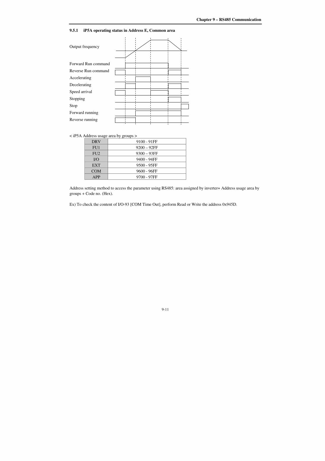
Chapter 9 – RS485 Communication
9-11
9.5.1 iP5A operating status in Address E, Common area
Output frequency
Forward Run command
Reverse Run command
Accelerating
Decelerating
Speed arrival
Stopping
Stop
Forward running
Reverse running
< iP5A Address usage area by groups >
DRV 9100 - 91FF
FU1 9200 – 92FF
FU2 9300 – 93FF
I/O 9400 - 94FF
EXT 9500 - 95FF
COM 9600 - 96FF
APP 9700 - 97FF
Address setting method to access the parameter using RS485: area assigned by inverter+ Address usage area by
groups + Code no. (Hex).
Ex) To check the content of I/O-93 [COM Time Out], perform Read or Write the address 0x945D.
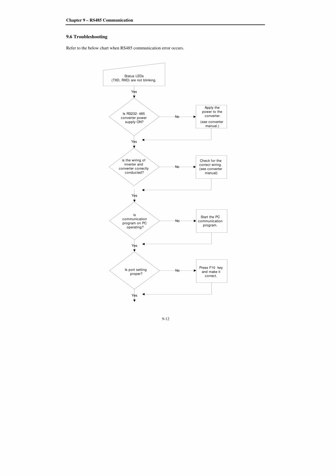
Chapter 9 – RS485 Communication
9-12
9.6 Troubleshooting
Refer to the below chart when RS485 communication error occurs.
Is RS232- 485
converter power
supply ON?
is the wiring of
inverter and
converter correctly conducted?
is
communication
program on PC operating?
Yes
Is port setting proper?
Yes
Yes
Yes
Yes
Apply the
power to the
converter.
(see converter
manual.)
No
Check for the correct wiring.
(see converter
manual)
No
Start the PC
communication
program.
No
Press F10 key
and make it correct.
No
Status LEDs
(TXD, RXD) are not blinking.
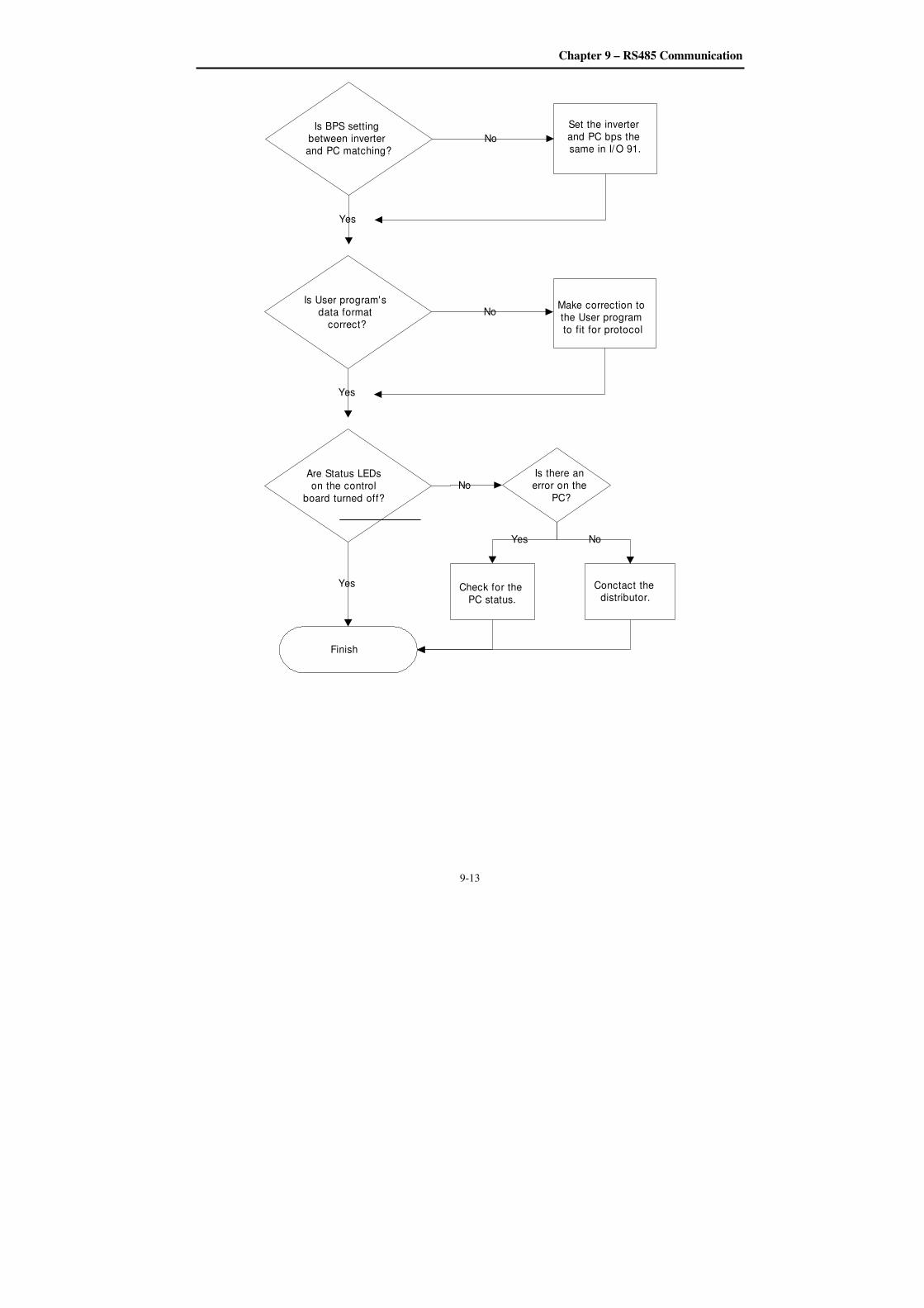
Chapter 9 – RS485 Communication
9-13
Is BPS setting between inverter and PC matching?
Set the inverter and PC bps the same in I/O 91.
No
Yes
Is User program's data format
correct?
Make correction to the User program to fit for protocol
No
Yes
Are Status LEDs on the control
board turned off?
Is there an error on the
PC?
No
Check for the
PC status.
Conctact the distributor.
Yes No
Finish
Yes
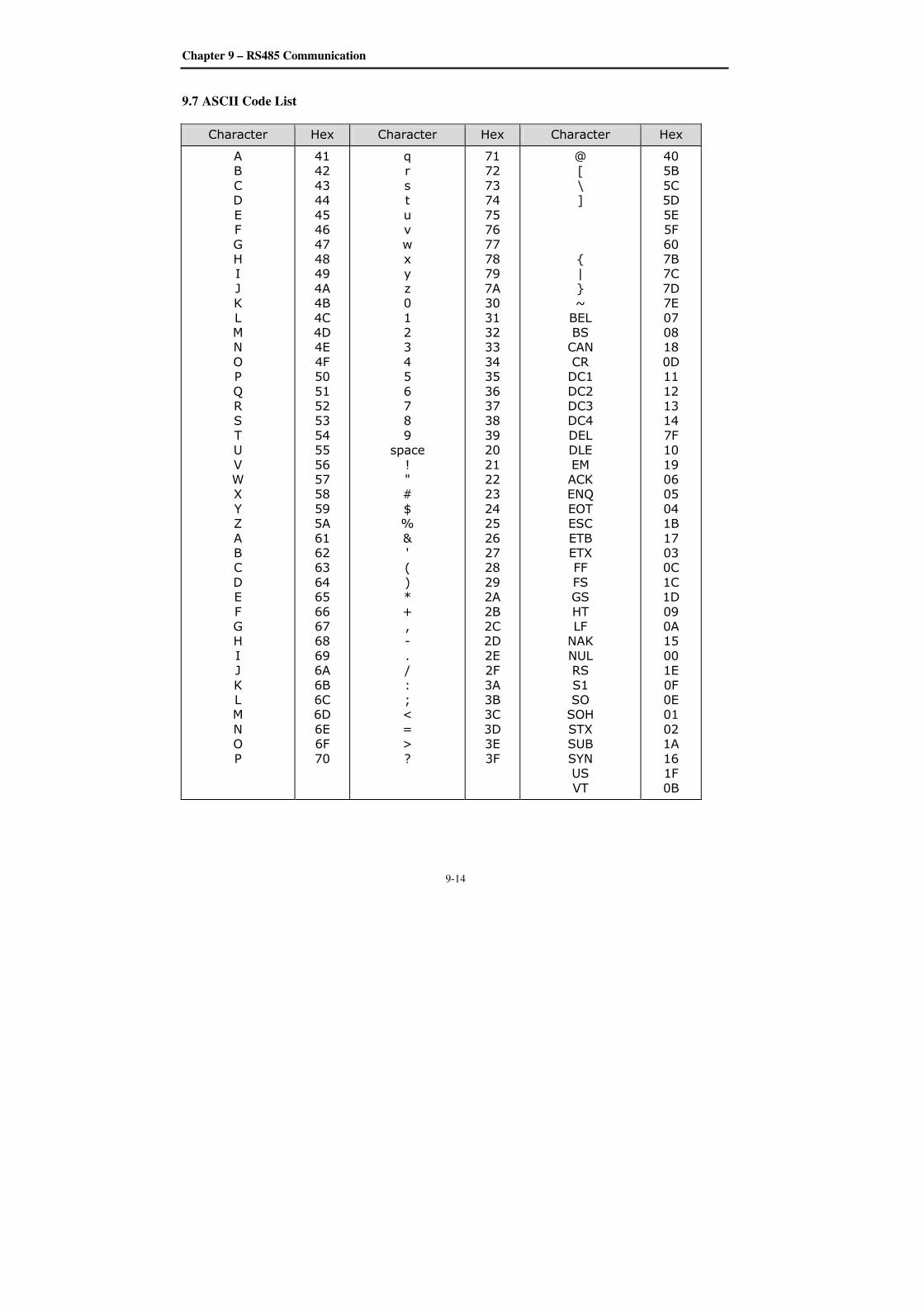
Chapter 9 – RS485 Communication
9-14
9.7 ASCII Code List
Character Hex Character Hex Character Hex
A B
C D
E F
G H I
J K
L M N
O P
Q R S
T U
V W X
Y Z
A B C
D E
F G H
I J
K L M
N O
P
41 42
43 44
45 46
47 48 49
4A 4B
4C 4D 4E
4F 50
51 52 53
54 55
56 57 58
59 5A
61 62 63
64 65
66 67 68
69 6A
6B 6C 6D
6E 6F
70
q r
s t
u v
w x y
z 0
1 2 3
4 5
6 7 8
9 space
! " #
$ %
& ' (
) *
+ , -
. /
: ; <
= >
?
71 72
73 74
75 76
77 78 79
7A 30
31 32 33
34 35
36 37 38
39 20
21 22 23
24 25
26 27 28
29 2A
2B 2C 2D
2E 2F
3A 3B 3C
3D 3E
3F
@ [
\ ]
|
~
BEL BS CAN
CR DC1
DC2 DC3 DC4
DEL DLE
EM ACK ENQ
EOT ESC
ETB ETX FF
FS GS
HT LF NAK
NUL RS
S1 SO SOH
STX SUB
SYN US
VT
40 5B
5C 5D
5E 5F
60 7B 7C
7D 7E
07 08 18
0D 11
12 13 14
7F 10
19 06 05
04 1B
17 03 0C
1C 1D
09 0A 15
00 1E
0F 0E 01
02 1A
16 1F
0B
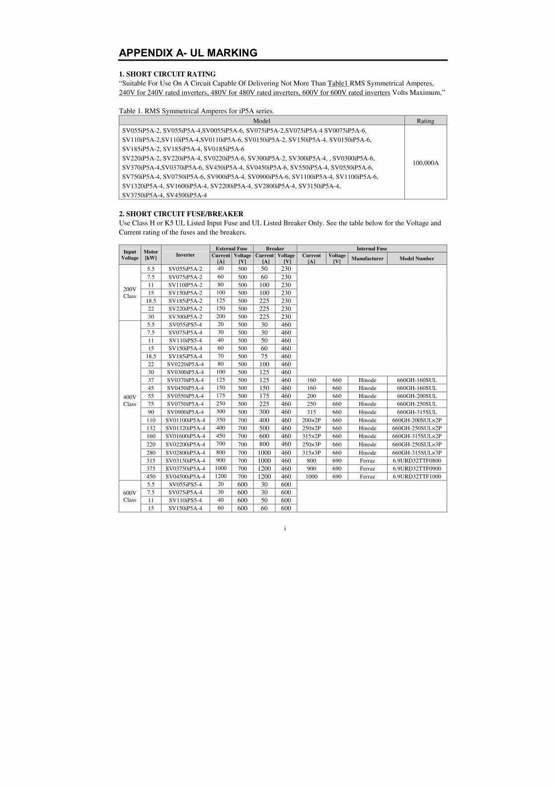
i
APPENDIX A- UL MARKING
1. SHORT CIRCUIT RATING
“Suitable For Use On A Circuit Capable Of Delivering Not More Than Table1 RMS Symmetrical Amperes,
240V for 240V rated inverters, 480V for 480V rated inverters, 600V for 600V rated inverters Volts Maximum,”
Table 1. RMS Symmetrical Amperes for iP5A series.
Model Rating
SV055iP5A-2, SV055iP5A-4,SV0055iP5A-6, SV075iP5A-2,SV075iP5A-4 SV0075iP5A-6,
SV110iP5A-2,SV110iP5A-4,SV0110iP5A-6, SV0150iP5A-2, SV150iP5A-4, SV0150iP5A-6,
SV185iP5A-2, SV185iP5A-4, SV0185iP5A-6
SV220iP5A-2, SV220iP5A-4, SV0220iP5A-6, SV300iP5A-2, SV300iP5A-4, , SV0300iP5A-6,
SV370iP5A-4,SV0370iP5A-6, SV450iP5A-4, SV0450iP5A-6, SV550iP5A-4, SV0550iP5A-6,
SV750iP5A-4, SV0750iP5A-6, SV900iP5A-4, SV0900iP5A-6, SV1100iP5A-4, SV1100iP5A-6,
SV1320iP5A-4, SV1600iP5A-4, SV2200iP5A-4, SV2800iP5A-4, SV3150iP5A-4,
SV3750iP5A-4, SV4500iP5A-4
100,000A
2. SHORT CIRCUIT FUSE/BREAKER
Use Class H or K5 UL Listed Input Fuse and UL Listed Breaker Only. See the table below for the Voltage and
Current rating of the fuses and the breakers.
Input Voltage
Motor [kW]
Inverter
External Fuse Breaker Internal Fuse
Current [A]
Voltage [V]
Current [A]
Voltage [V]
Current [A]
Voltage [V]
Manufacturer Model Number
200V
Class
5.5 SV055iP5A-2 40 500 50 230
7.5 SV075iP5A-2 60 500 60 230
11 SV110IP5A-2 80 500 100 230
15 SV150iP5A-2 100 500 100 230
18.5 SV185iP5A-2 125 500 225 230
22 SV220iP5A-2 150 500 225 230
30 SV300iP5A-2 200 500 225 230
400V
Class
5.5 SV055iPS5-4 20 500 30 460
7.5 SV075iP5A-4 30 500 30 460
11 SV110iPS5-4 40 500 50 460
15 SV150iP5A-4 60 500 60 460
18.5 SV185iP5A-4 70 500 75 460
22 SV0220iP5A-4 80 500 100 460
30 SV0300iP5A-4 100 500 125 460
37 SV0370iP5A-4 125 500 125 460 160 660 Hinode 660GH-160SUL
45 SV0450iP5A-4 150 500 150 460 160 660 Hinode 660GH-160SUL
55 SV0550iP5A-4 175 500 175 460 200 660 Hinode 660GH-200SUL
75 SV0750iP5A-4 250 500 225 460 250 660 Hinode 660GH-250SUL
90 SV0900iP5A-4 300 500 300 460 315 660 Hinode 660GH-315SUL
110 SV01100iP5A-4 350 700 400 460 200×2P 660 Hinode 660GH-200SUL×2P
132 SV01320iP5A-4 400 700 500 460 250×2P 660 Hinode 660GH-250SUL×2P
160 SV01600iP5A-4 450 700 600 460 315×2P 660 Hinode 660GH-315SUL×2P
220 SV02200iP5A-4 700 700 800 460 250×3P 660 Hinode 660GH-250SUL×3P
280 SV02800iP5A-4 800 700 1000 460 315×3P 660 Hinode 660GH-315SUL×3P
315 SV03150iP5A-4 900 700 1000 460 800 690 Ferraz 6.9URD32TTF0800
375 SV03750iP5A-4 1000 700 1200 460 900 690 Ferraz 6.9URD32TTF0900
450 SV04500iP5A-4 1200 700 1200 460 1000 690 Ferraz 6.9URD32TTF1000
600V
Class
5.5 SV055iPS5-4 20 600 30 600
7.5 SV075iP5A-4 30 600 30 600
11 SV110iPS5-4 40 600 50 600
15 SV150iP5A-4 60 600 60 600
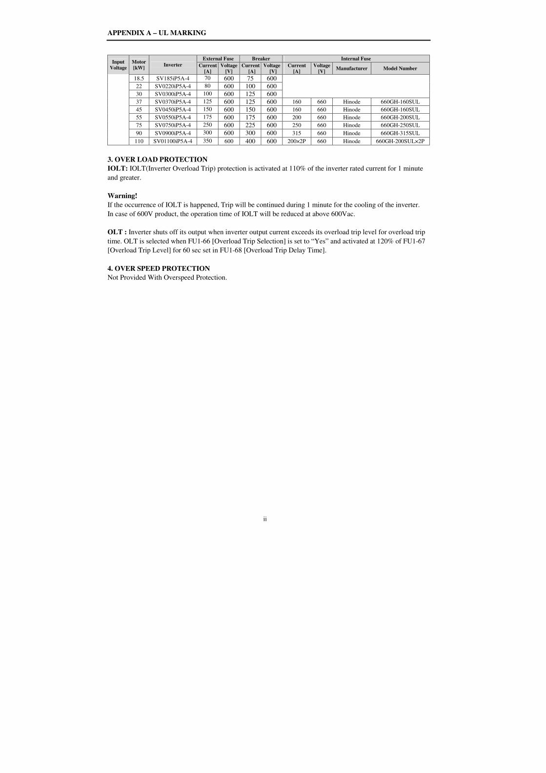
APPENDIX A – UL MARKING
ii
Input Voltage
Motor [kW]
Inverter
External Fuse Breaker Internal Fuse
Current [A]
Voltage [V]
Current [A]
Voltage [V]
Current [A]
Voltage [V]
Manufacturer Model Number
18.5 SV185iP5A-4 70 600 75 600
22 SV0220iP5A-4 80 600 100 600
30 SV0300iP5A-4 100 600 125 600
37 SV0370iP5A-4 125 600 125 600 160 660 Hinode 660GH-160SUL
45 SV0450iP5A-4 150 600 150 600 160 660 Hinode 660GH-160SUL
55 SV0550iP5A-4 175 600 175 600 200 660 Hinode 660GH-200SUL
75 SV0750iP5A-4 250 600 225 600 250 660 Hinode 660GH-250SUL
90 SV0900iP5A-4 300 600 300 600 315 660 Hinode 660GH-315SUL
110 SV01100iP5A-4 350 600 400 600 200×2P 660 Hinode 660GH-200SUL×2P
3. OVER LOAD PROTECTION
IOLT: IOLT(Inverter Overload Trip) protection is activated at 110% of the inverter rated current for 1 minute
and greater.
Warning!
If the occurrence of IOLT is happened, Trip will be continued during 1 minute for the cooling of the inverter.
In case of 600V product, the operation time of IOLT will be reduced at above 600Vac.
OLT : Inverter shuts off its output when inverter output current exceeds its overload trip level for overload trip
time. OLT is selected when FU1-66 [Overload Trip Selection] is set to “Yes” and activated at 120% of FU1-67
[Overload Trip Level] for 60 sec set in FU1-68 [Overload Trip Delay Time].
4. OVER SPEED PROTECTION
Not Provided With Overspeed Protection.
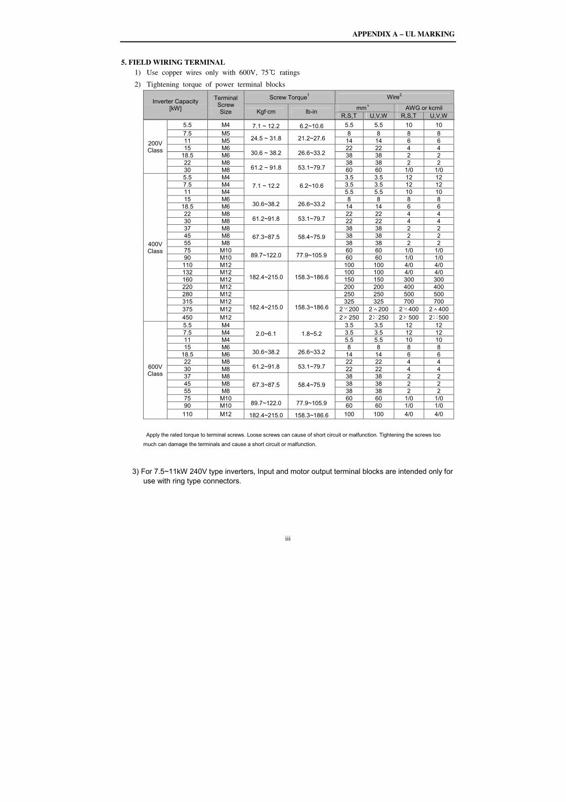
APPENDIX A – UL MARKING
iii
5. FIELD WIRING TERMINAL
1) Use copper wires only with 600V, 75 ratings
2) Tightening torque of power terminal blocks
Inverter Capacity [kW]
Terminal Screw Size
Screw Torque1 Wire2
Kgf·cm lb-in mm² AWG or kcmil
R,S,T U,V,W R,S,T U,V,W
200V Class
5.5 M4 7.1 ~ 12.2 6.2~10.6 5.5 5.5 10 10
7.5 M5 24.5 ~ 31.8 21.2~27.6
8 8 8 8 11 M5 14 14 6 6 15 M6
30.6 ~ 38.2 26.6~33.2 22 22 4 4
18.5 M6 38 38 2 2 22 M8
61.2 ~ 91.8 53.1~79.7 38 38 2 2
30 M8 60 60 1/0 1/0
400V Class
5.5 M4
7.1 ~ 12.2 6.2~10.6
3.5 3.5 12 12 7.5 M4 3.5 3.5 12 12 11 M4 5.5 5.5 10 10 15 M6
30.6~38.2 26.6~33.2 8 8 8 8
18.5 M6 14 14 6 6 22 M8
61.2~91.8 53.1~79.7 22 22 4 4
30 M8 22 22 4 4 37 M8
67.3~87.5 58.4~75.9
38 38 2 2 45 M8 38 38 2 2 55 M8 38 38 2 2 75 M10
89.7~122.0 77.9~105.9 60 60 1/0 1/0
90 M10 60 60 1/0 1/0 110 M12
182.4~215.0 158.3~186.6
100 100 4/0 4/0 132 M12 100 100 4/0 4/0 160 M12 150 150 300 300 220 M12 200 200 400 400 280 M12
182.4~215.0 158.3~186.6
250 250 500 500 315 M12 325 325 700 700 375 M12 2×200 2×200 2×400 2×400 450 M12 2×250 2×250 2×500 2×500
600V Class
5.5 M4
2.0~6.1 1.8~5.2
3.5 3.5 12 12 7.5 M4 3.5 3.5 12 12 11 M4 5.5 5.5 10 10 15 M6
30.6~38.2 26.6~33.2 8 8 8 8
18.5 M6 14 14 6 6 22 M8
61.2~91.8 53.1~79.7 22 22 4 4
30 M8 22 22 4 4 37 M8
67.3~87.5 58.4~75.9
38 38 2 2 45 M8 38 38 2 2 55 M8 38 38 2 2 75 M10
89.7~122.0 77.9~105.9 60 60 1/0 1/0
90 M10 60 60 1/0 1/0
110 M12 182.4~215.0 158.3~186.6 100 100 4/0 4/0
Apply the rated torque to terminal screws. Loose screws can cause of short circuit or malfunction. Tightening the screws too
much can damage the terminals and cause a short circuit or malfunction.
3) For 7.5~11kW 240V type inverters, Input and motor output terminal blocks are intended only for
use with ring type connectors.
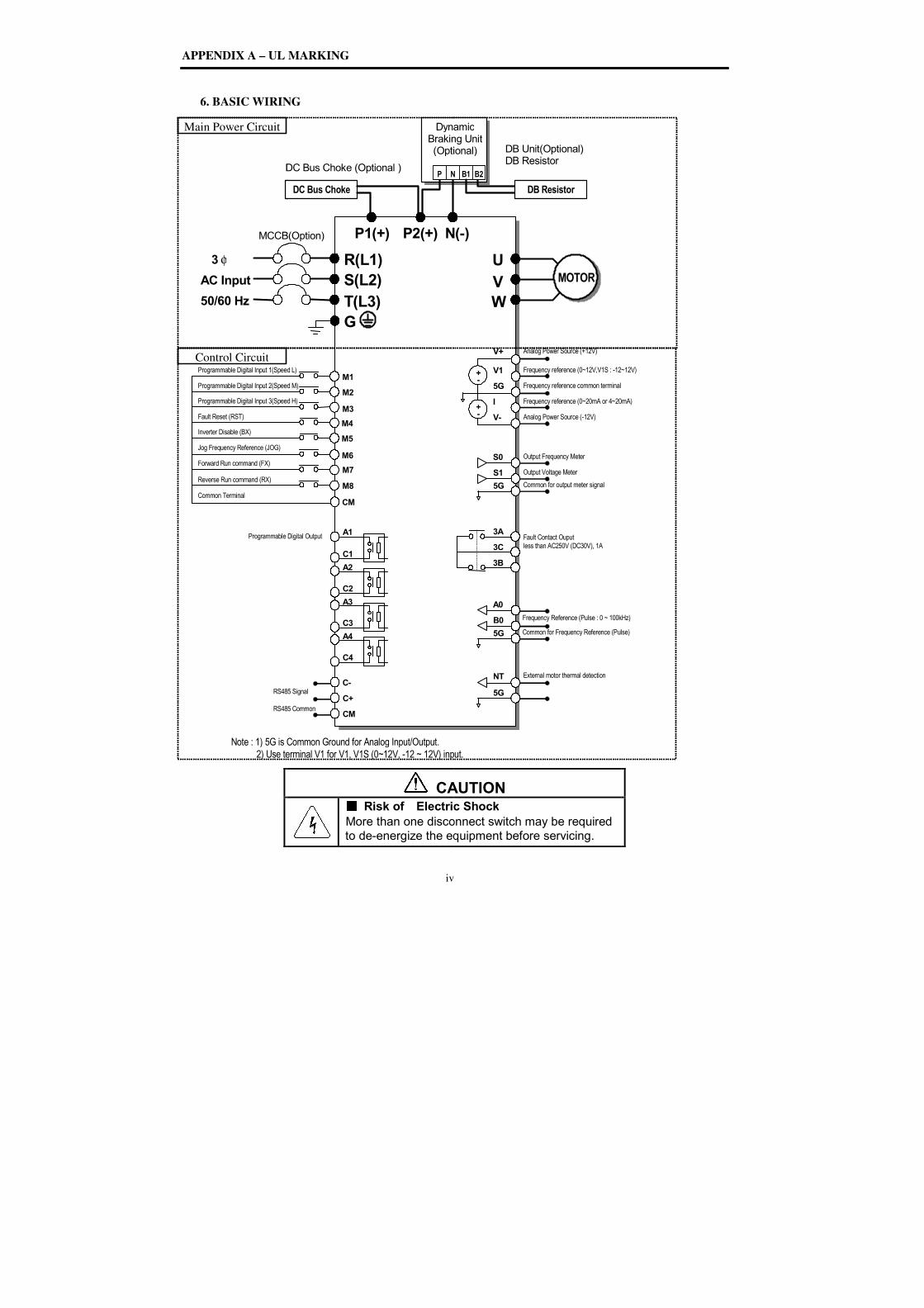
APPENDIX A – UL MARKING
6. BASIC WIRING
AC Input
50/60 Hz
φ 3
MCCB
Programmable Digital Input 1(Speed L)
Programmable Digital Input 2(Speed M)
Programmable Digital Input 3(Speed H)
Fault Reset (RST)
Jog Frequency Reference (JOG)
Forward Run command (FX)
Reverse Run command (RX)
Common Terminal
DC Bus Cho
Inverter Disable (BX)
RS485 Signal
RS485 Common
Note : 1) 5G is Common Ground for Analog Input/Output.
2) Use terminal V1 for
Programmable Digital Output
Control Circuit
Main Power Circuit
UL MARKING
iv
ASIC WIRING
G
R(L1)
S(L2)
T(L3)
N(MCCB(Option)
M1
M2
M3
M4
M6
M8
M7
Programmable Digital Input 1(Speed L)
Programmable Digital Input 2(Speed M)
peed H)
P2(+)
P1(+)
DC Bus Choke (Optional )
DynamicBraking Unit(Optional)
P N
DC Bus Choke
M5
A1
C1
A2
C2
A3
C3
A4
C4
C-
C+
CM
RS485 Signal
RS485 Common
CM
Note : 1) 5G is Common Ground for Analog Input/Output.
2) Use terminal V1 for V1, V1S (0~12V, -12 ~ 12V) input.
Programmable Digital Output
CAUTION
Risk of Electric ShockMore than one disconnect switch may be required to de-energize the equipment before servicing.
iv
U
V
W
N(-)
DB Unit(Optional)
DB Resistor
MOTOR
Fault Contact Ouput
less than AC250V (DC30V), 1A
Dynamic Braking Unit (Optional)
N B1 B2
DB Resistor
V+
V1
5G
V-
I
Analog Power Source (+12V)
+ -
+ -
Analog Power Source (-12V)
Frequency reference (0~20mA or 4~20mA)
Frequency reference (0~12V,V1S : -12~12V)
Frequency reference common terminal
S1
S0
5G
Output Frequency Meter
Output Voltage Meter
Common for output meter signal
3A
3C
3B
5G
B0
A0
Frequency Reference (Pulse : 0 ~ 100kHz)
Common for Frequency Reference (Pulse)
5G
NT External motor thermal detection
~ 12V) input.
CAUTION Risk of Electric Shock
More than one disconnect switch may be required energize the equipment before servicing.
Frequency reference (0~20mA or 4~20mA)
12~12V)
Frequency reference common terminal
Frequency Reference (Pulse : 0 ~ 100kHz)
Common for Frequency Reference (Pulse)
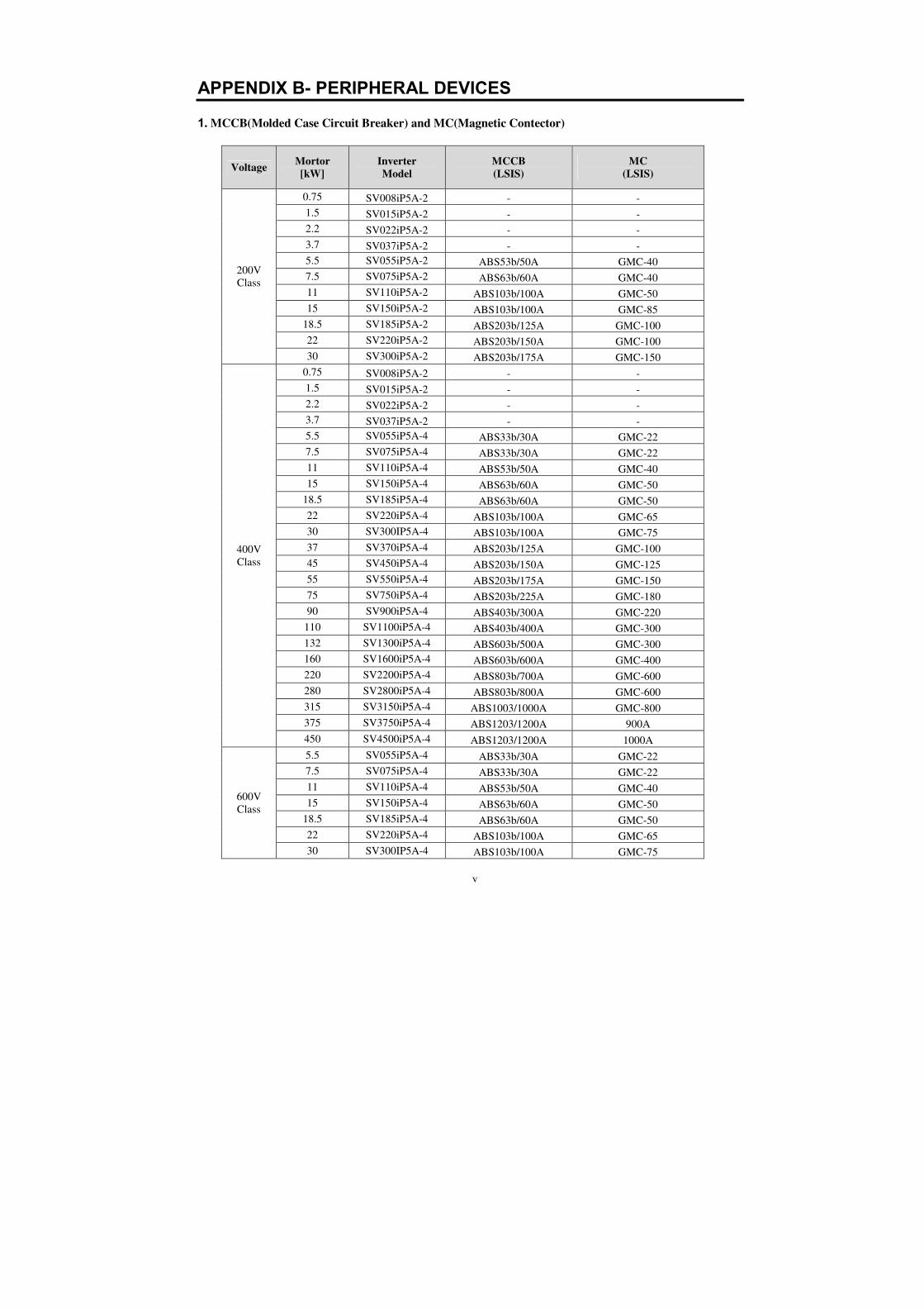
v
APPENDIX B- PERIPHERAL DEVICES
1. MCCB(Molded Case Circuit Breaker) and MC(Magnetic Contector)
Voltage Mortor [kW]
Inverter Model
MCCB (LSIS)
MC (LSIS)
200V
Class
0.75 SV008iP5A-2 - -
1.5 SV015iP5A-2 - -
2.2 SV022iP5A-2 - -
3.7 SV037iP5A-2 - -
5.5 SV055iP5A-2 ABS53b/50A GMC-40
7.5 SV075iP5A-2 ABS63b/60A GMC-40
11 SV110iP5A-2 ABS103b/100A GMC-50
15 SV150iP5A-2 ABS103b/100A GMC-85
18.5 SV185iP5A-2 ABS203b/125A GMC-100
22 SV220iP5A-2 ABS203b/150A GMC-100
30 SV300iP5A-2 ABS203b/175A GMC-150
400V
Class
0.75 SV008iP5A-2 - -
1.5 SV015iP5A-2 - -
2.2 SV022iP5A-2 - -
3.7 SV037iP5A-2 - -
5.5 SV055iP5A-4 ABS33b/30A GMC-22
7.5 SV075iP5A-4 ABS33b/30A GMC-22
11 SV110iP5A-4 ABS53b/50A GMC-40
15 SV150iP5A-4 ABS63b/60A GMC-50
18.5 SV185iP5A-4 ABS63b/60A GMC-50
22 SV220iP5A-4 ABS103b/100A GMC-65
30 SV300IP5A-4 ABS103b/100A GMC-75
37 SV370iP5A-4 ABS203b/125A GMC-100
45 SV450iP5A-4 ABS203b/150A GMC-125
55 SV550iP5A-4 ABS203b/175A GMC-150
75 SV750iP5A-4 ABS203b/225A GMC-180
90 SV900iP5A-4 ABS403b/300A GMC-220
110 SV1100iP5A-4 ABS403b/400A GMC-300
132 SV1300iP5A-4 ABS603b/500A GMC-300
160 SV1600iP5A-4 ABS603b/600A GMC-400
220 SV2200iP5A-4 ABS803b/700A GMC-600
280 SV2800iP5A-4 ABS803b/800A GMC-600
315 SV3150iP5A-4 ABS1003/1000A GMC-800
375 SV3750iP5A-4 ABS1203/1200A 900A
450 SV4500iP5A-4 ABS1203/1200A 1000A
600V
Class
5.5 SV055iP5A-4 ABS33b/30A GMC-22
7.5 SV075iP5A-4 ABS33b/30A GMC-22
11 SV110iP5A-4 ABS53b/50A GMC-40
15 SV150iP5A-4 ABS63b/60A GMC-50
18.5 SV185iP5A-4 ABS63b/60A GMC-50
22 SV220iP5A-4 ABS103b/100A GMC-65
30 SV300IP5A-4 ABS103b/100A GMC-75

APPENDIX B – PERIPHERAL DEVICES
vi
Voltage Mortor [kW]
Inverter Model
MCCB (LSIS)
MC (LSIS)
37 SV370iP5A-4 ABS203b/125A GMC-100
45 SV450iP5A-4 ABS203b/150A GMC-125
55 SV550iP5A-4 ABS203b/175A GMC-150
75 SV750iP5A-4 ABS203b/225A GMC-180
90 SV900iP5A-4 ABS403b/300A GMC-220
110 SV1100iP5A-4 ABS403b/400A GMC-300
2. AC Input Fuse and AC / DC Reactor
Voltage Mortor [kW]
Inverter Model
AC Input Fuse [A]
AC Reactor DC Reactor
[mH] [A] [mH] [A]
200V
Class
0.75 SV008iP5A-2 10 2.13 5.7 - -
1.5 SV015iP5A-2 15 1.2 10 - -
2.2 SV022iP5A-2 20 0.88 14 - -
3.7 SV037iP5A-2 30 0.56 20 - -
5.5 SV055iP5A-2 40 0.39 30 1.37 29
7.5 SV075iP5A-2 60 0.28 40 1.05 38
11 SV110iP5A-2 80 0.20 59 0.74 56
15 SV150iP5A-2 100 0.15 75 0.57 71
18.5 SV185iP5A-2 125 0.12 96 0.49 91
22 SV220iP5A-2 150 0.10 112 0.42 107
30 SV300iP5A-2 200 0.07 160 0.34 152
400V
Class
0.75 SV008iP5A-4 10 8.63 2.8 - -
1.5 SV015iP5A-4 10 4.81 4.8 - -
2.2 SV022iP5A-4 10 3.23 7.5 - -
3.7 SV037iP5A-4 15 2.34 10 - -
5.5 SV055iP5A-4 20 1.22 15 5.34 14
7.5 SV075iP5A-4 30 1.14 20 4.04 19
11 SV110iP5A-4 40 0.81 30 2.76 29
15 SV150iP5A-4 60 0.61 38 2.18 36
18.5 SV185iP5A-4 70 0.45 50 1.79 48
22 SV220iP5A-4 80 0.39 58 1.54 55
30 SV300IP5A-4 100 0.287 80 1.191 76
37 SV370iP5A-4 125 0.232 98 0.975 93
45 SV450iP5A-4 150 0.195 118 0.886 112
55 SV550iP5A-4 175 0.157 142 0.753 135
75 SV750iP5A-4 250 0.122 196 0.436 187
90 SV900iP5A-4 300 0.096 237 0.352 225
110 SV1100iP5A-4 350 0.081 289 Built-in
132 SV1300iP5A-4 400 0.069 341 Built-in
160 SV1600iP5A-4 450 0.057 420 Built-in
220 SV2200iP5A-4 700 0.042 558 Built-in
280 SV2800iP5A-4 800 0.029 799 Built-in
315 SV3150iP5A-4 900 0.029 799 0.090 836
375 SV3750iP5A-4 1000 0.024 952 0.076 996
450 SV4500iP5A-4 1200 0.024 952 0.064 1195
600V
Class
5.5 SV0055iP5A-6 15 2.45 12 9.32 11
7.5 SV0075iP5A-6 20 1.80 16 6.27 15
11 SV0110iP5A-6 30 1.23 23 4.60 22

vii
15 SV0150iP5A-6 40 0.900 32 3.82 30
18.5 SV0185iP5A-6 50 0.730 39 2.80 37
22 SV0220iP5A-6 60 0.614 47 2.27 44
30 SV0300IP5A-6 80 0.450 63 1.91 60
37 SV0370iP5A-6 100 0.365 78 1.40 75
45 SV0450iP5A-6 125 0.300 95 1.13 91
55 SV0550iP5A-6 150 0.245 116 0.933 111
75 SV0750iP5A-6 175 0.180 159 0.763 151
90 SV0900iP5A-6 250 0.150 190 0.560 181
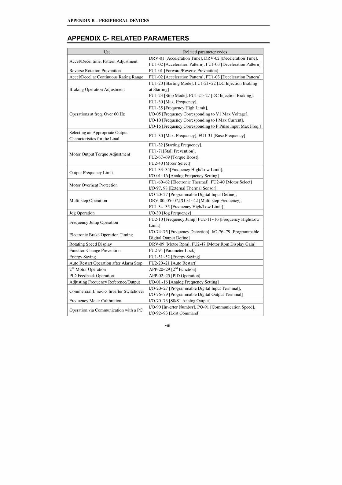
APPENDIX B – PERIPHERAL DEVICES
viii
APPENDIX C- RELATED PARAMETERS
Use Related parameter codes
Accel/Decel time, Pattern Adjustment DRV-01 [Acceleration Time], DRV-02 [Deceleration Time],
FU1-02 [Acceleration Pattern], FU1-03 [Deceleration Pattern]
Reverse Rotation Prevention FU1-01 [Forward/Reverse Prevention]
Accel/Decel at Continuous Rating Range FU1-02 [Acceleration Pattern], FU1-03 [Deceleration Pattern]
Braking Operation Adjustment
FU1-20 [Starting Mode], FU1-21~22 [DC Injection Braking
at Starting]
FU1-23 [Stop Mode], FU1-24~27 [DC Injection Braking],
Operations at freq. Over 60 Hz
FU1-30 [Max. Frequency],
FU1-35 [Frequency High Limit],
I/O-05 [Frequency Corresponding to V1 Max Voltage],
I/O-10 [Frequency Corresponding to I Max Current],
I/O-16 [Frequency Corresponding to P Pulse Input Max Freq.]
Selecting an Appropriate Output
Characteristics for the Load FU1-30 [Max. Frequency], FU1-31 [Base Frequency]
Motor Output Torque Adjustment
FU1-32 [Starting Frequency],
FU1-71[Stall Prevention],
FU2-67~69 [Torque Boost],
FU2-40 [Motor Select]
Output Frequency Limit FU1-33~35[Frequency High/Low Limit],
I/O-01~16 [Analog Frequency Setting]
Motor Overheat Protection FU1-60~62 [Electronic Thermal], FU2-40 [Motor Select]
I/O-97, 98 [External Thermal Sensor]
Multi-step Operation
I/O-20~27 [Programmable Digital Input Define],
DRV-00, 05~07,I/O-31~42 [Multi-step Frequency],
FU1-34~35 [Frequency High/Low Limit]
Jog Operation I/O-30 [Jog Frequency]
Frequency Jump Operation FU2-10 [Frequency Jump] FU2-11~16 [Frequency High/Low
Limit]
Electronic Brake Operation Timing I/O-74~75 [Frequency Detection], I/O-76~79 [Programmable
Digital Output Define]
Rotating Speed Display DRV-09 [Motor Rpm], FU2-47 [Motor Rpm Display Gain]
Function Change Prevention FU2-94 [Parameter Lock]
Energy Saving FU1-51~52 [Energy Saving]
Auto Restart Operation after Alarm Stop FU2-20~21 [Auto Restart]
2nd
Motor Operation APP-20~29 [2nd
Function]
PID Feedback Operation APP-02~25 [PID Operation]
Adjusting Frequency Reference/Output I/O-01~16 [Analog Frequency Setting]
Commercial Line<-> Inverter Switchover I/O-20~27 [Programmable Digital Input Terminal],
I/O-76~79 [Programmable Digital Output Terminal]
Frequency Meter Calibration I/O-70~73 [S0/S1 Analog Output]
Operation via Communication with a PC I/O-90 [Inverter Number], I/O-91 [Communication Speed],
I/O-92~93 [Lost Command]
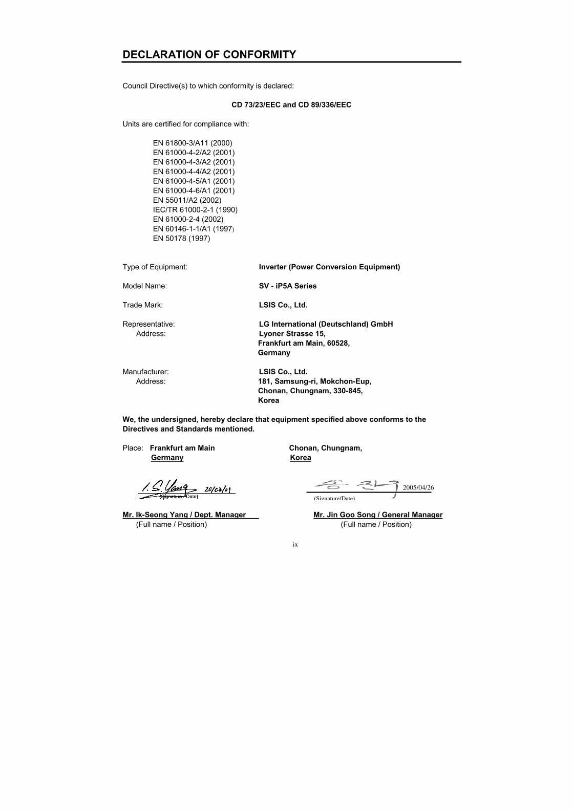
ix
DECLARATION OF CONFORMITY
Council Directive(s) to which conformity is declared:
CD 73/23/EEC and CD 89/336/EEC
Units are certified for compliance with:
EN 61800-3/A11 (2000) EN 61000-4-2/A2 (2001) EN 61000-4-3/A2 (2001) EN 61000-4-4/A2 (2001) EN 61000-4-5/A1 (2001) EN 61000-4-6/A1 (2001) EN 55011/A2 (2002) IEC/TR 61000-2-1 (1990) EN 61000-2-4 (2002) EN 60146-1-1/A1 (1997) EN 50178 (1997)
Type of Equipment: Inverter (Power Conversion Equipment) Model Name: SV - iP5A Series Trade Mark: LSIS Co., Ltd. Representative: LG International (Deutschland) GmbH
Address: Lyoner Strasse 15, Frankfurt am Main, 60528, Germany Manufacturer: LSIS Co., Ltd. Address: 181, Samsung-ri, Mokchon-Eup, Chonan, Chungnam, 330-845, Korea
We, the undersigned, hereby declare that equipment specified above conforms to the
Directives and Standards mentioned.
Place: Frankfurt am Main Chonan, Chungnam,
Germany Korea
Mr. Ik-Seong Yang / Dept. Manager Mr. Jin Goo Song / General Manager (Full name / Position) (Full name / Position)
(Signature/Date)
2005/04/26
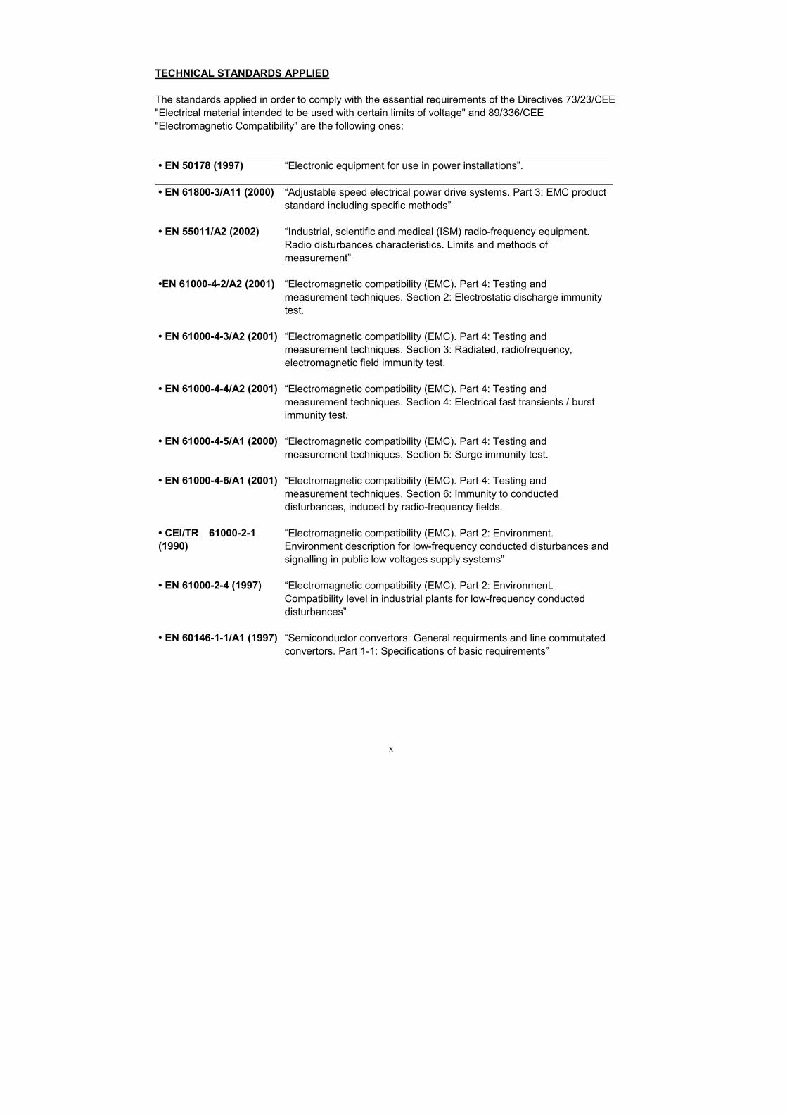
x
TECHNICAL STANDARDS APPLIED
The standards applied in order to comply with the essential requirements of the Directives 73/23/CEE "Electrical material intended to be used with certain limits of voltage" and 89/336/CEE "Electromagnetic Compatibility" are the following ones:
• EN 50178 (1997) “Electronic equipment for use in power installations”.
• EN 61800-3/A11 (2000) “Adjustable speed electrical power drive systems. Part 3: EMC product standard including specific methods”
• EN 55011/A2 (2002) “Industrial, scientific and medical (ISM) radio-frequency equipment. Radio disturbances characteristics. Limits and methods of measurement”
•EN 61000-4-2/A2 (2001) “Electromagnetic compatibility (EMC). Part 4: Testing and measurement techniques. Section 2: Electrostatic discharge immunity test.
• EN 61000-4-3/A2 (2001) “Electromagnetic compatibility (EMC). Part 4: Testing and measurement techniques. Section 3: Radiated, radiofrequency, electromagnetic field immunity test.
• EN 61000-4-4/A2 (2001) “Electromagnetic compatibility (EMC). Part 4: Testing and measurement techniques. Section 4: Electrical fast transients / burst immunity test.
• EN 61000-4-5/A1 (2000) “Electromagnetic compatibility (EMC). Part 4: Testing and measurement techniques. Section 5: Surge immunity test.
• EN 61000-4-6/A1 (2001) “Electromagnetic compatibility (EMC). Part 4: Testing and measurement techniques. Section 6: Immunity to conducted disturbances, induced by radio-frequency fields.
• CEI/TR 61000-2-1
(1990)
“Electromagnetic compatibility (EMC). Part 2: Environment. Environment description for low-frequency conducted disturbances and signalling in public low voltages supply systems”
• EN 61000-2-4 (1997) “Electromagnetic compatibility (EMC). Part 2: Environment. Compatibility level in industrial plants for low-frequency conducted disturbances”
• EN 60146-1-1/A1 (1997) “Semiconductor convertors. General requirments and line commutated convertors. Part 1-1: Specifications of basic requirements”
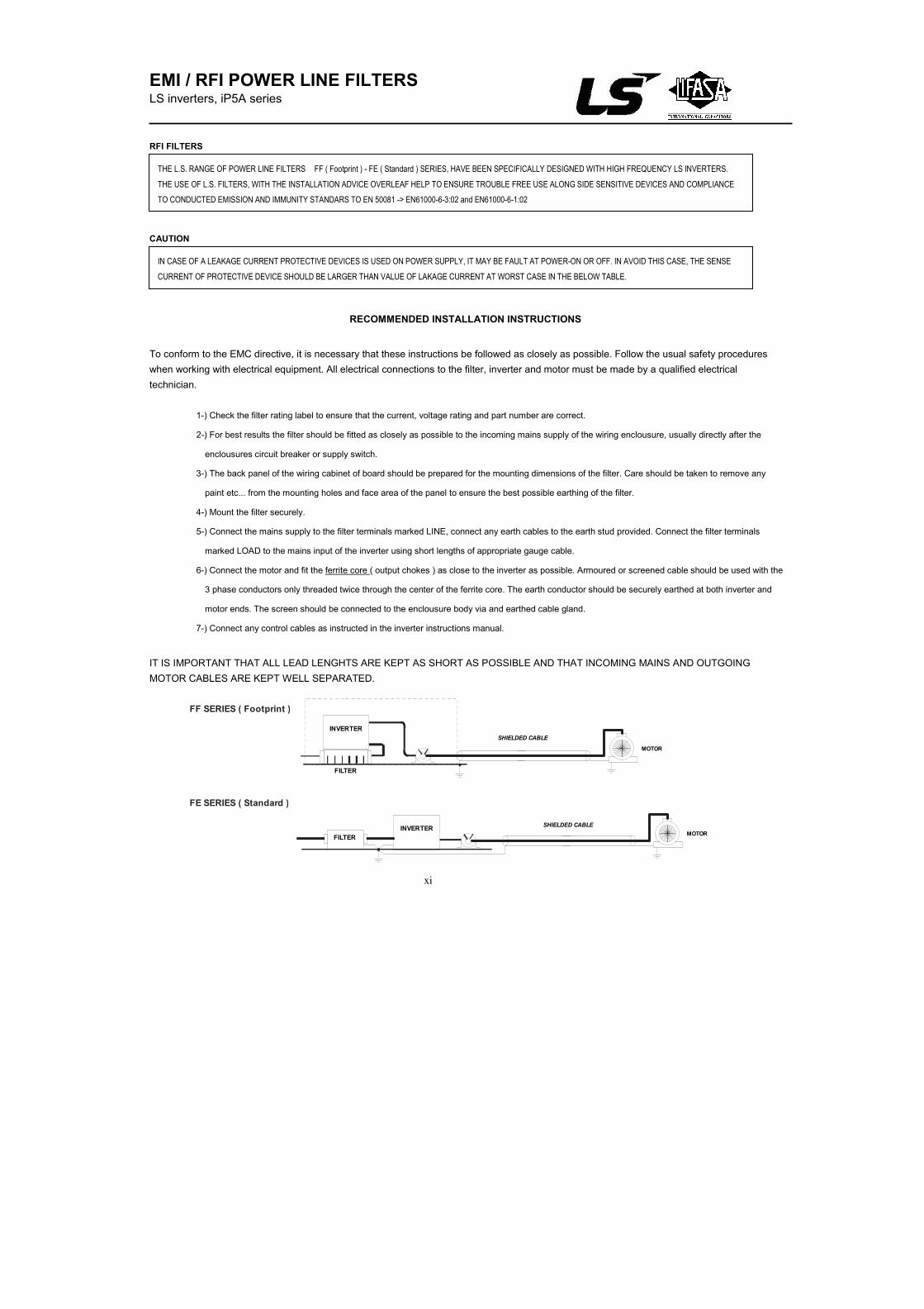
xi
EMI / RFI POWER LINE FILTERS LS inverters, iP5A series RFI FILTERS
CAUTION
RECOMMENDED INSTALLATION INSTRUCTIONS
To conform to the EMC directive, it is necessary that these instructions be followed as closely as possible. Follow the usual safety procedures
when working with electrical equipment. All electrical connections to the filter, inverter and motor must be made by a qualified electrical
technician.
1-) Check the filter rating label to ensure that the current, voltage rating and part number are correct.
2-) For best results the filter should be fitted as closely as possible to the incoming mains supply of the wiring enclousure, usually directly after the
enclousures circuit breaker or supply switch.
3-) The back panel of the wiring cabinet of board should be prepared for the mounting dimensions of the filter. Care should be taken to remove any
paint etc... from the mounting holes and face area of the panel to ensure the best possible earthing of the filter.
4-) Mount the filter securely.
5-) Connect the mains supply to the filter terminals marked LINE, connect any earth cables to the earth stud provided. Connect the filter terminals
marked LOAD to the mains input of the inverter using short lengths of appropriate gauge cable.
6-) Connect the motor and fit the ferrite core ( output chokes ) as close to the inverter as possible. Armoured or screened cable should be used with the
3 phase conductors only threaded twice through the center of the ferrite core. The earth conductor should be securely earthed at both inverter and
motor ends. The screen should be connected to the enclousure body via and earthed cable gland.
7-) Connect any control cables as instructed in the inverter instructions manual.
IT IS IMPORTANT THAT ALL LEAD LENGHTS ARE KEPT AS SHORT AS POSSIBLE AND THAT INCOMING MAINS AND OUTGOING
MOTOR CABLES ARE KEPT WELL SEPARATED.
THE L.S. RANGE OF POWER LINE FILTERS FF ( Footprint ) - FE ( Standard ) SERIES, HAVE BEEN SPECIFICALLY DESIGNED WITH HIGH FREQUENCY LS INVERTERS.
THE USE OF L.S. FILTERS, WITH THE INSTALLATION ADVICE OVERLEAF HELP TO ENSURE TROUBLE FREE USE ALONG SIDE SENSITIVE DEVICES AND COMPLIANCE
TO CONDUCTED EMISSION AND IMMUNITY STANDARS TO EN 50081 -> EN61000-6-3:02 and EN61000-6-1:02
IN CASE OF A LEAKAGE CURRENT PROTECTIVE DEVICES IS USED ON POWER SUPPLY, IT MAY BE FAULT AT POWER-ON OR OFF. IN AVOID THIS CASE, THE SENSE
CURRENT OF PROTECTIVE DEVICE SHOULD BE LARGER THAN VALUE OF LAKAGE CURRENT AT WORST CASE IN THE BELOW TABLE.
FF SERIES ( Footprint )
FE SERIES ( Standard )
INVERTER
FILTER
MOTOR
SHIELDED CABLE
FILTER
INVERTERMOTOR
SHIELDED CABLE
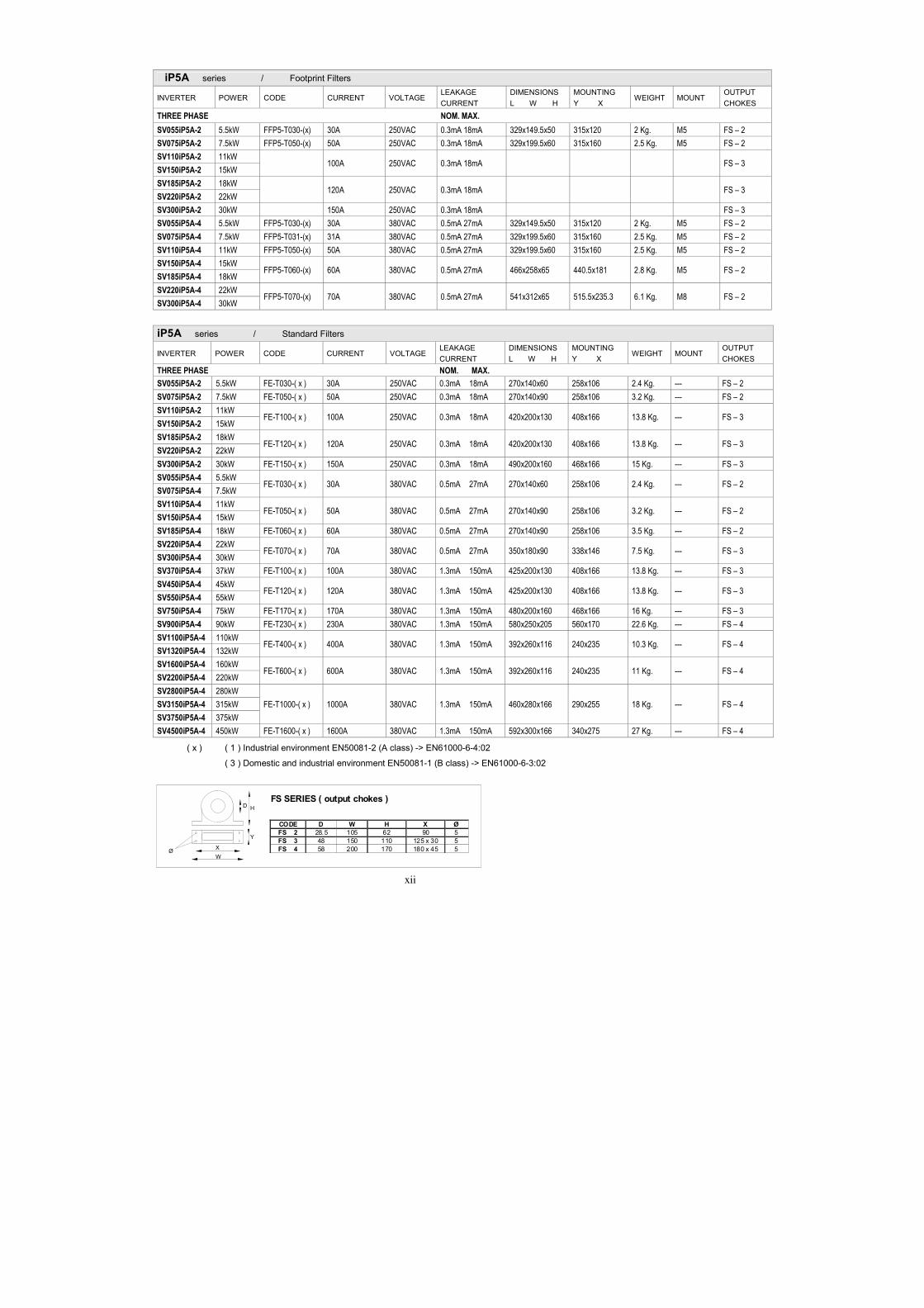
xii
iP5A series / Footprint Filters
INVERTER POWER CODE CURRENT VOLTAGE LEAKAGE
CURRENT
DIMENSIONS
L W H
MOUNTING
Y X WEIGHT MOUNT
OUTPUT
CHOKES
THREE PHASE NOM. MAX.
SV055iP5A-2 5.5kW FFP5-T030-(x) 30A 250VAC 0.3mA 18mA 329x149.5x50 315x120 2 Kg. M5 FS – 2
SV075iP5A-2 7.5kW FFP5-T050-(x) 50A 250VAC 0.3mA 18mA 329x199.5x60 315x160 2.5 Kg. M5 FS – 2
SV110iP5A-2 11kW 100A 250VAC 0.3mA 18mA FS – 3
SV150iP5A-2 15kW
SV185iP5A-2 18kW 120A 250VAC 0.3mA 18mA FS – 3
SV220iP5A-2 22kW
SV300iP5A-2 30kW 150A 250VAC 0.3mA 18mA FS – 3
SV055iP5A-4 5.5kW FFP5-T030-(x) 30A 380VAC 0.5mA 27mA 329x149.5x50 315x120 2 Kg. M5 FS – 2
SV075iP5A-4 7.5kW FFP5-T031-(x) 31A 380VAC 0.5mA 27mA 329x199.5x60 315x160 2.5 Kg. M5 FS – 2
SV110iP5A-4 11kW FFP5-T050-(x) 50A 380VAC 0.5mA 27mA 329x199.5x60 315x160 2.5 Kg. M5 FS – 2
SV150iP5A-4 15kW FFP5-T060-(x) 60A 380VAC 0.5mA 27mA 466x258x65 440.5x181 2.8 Kg. M5 FS – 2
SV185iP5A-4 18kW
SV220iP5A-4 22kW FFP5-T070-(x) 70A 380VAC 0.5mA 27mA 541x312x65 515.5x235.3 6.1 Kg. M8 FS – 2
SV300iP5A-4 30kW
iP5A series / Standard Filters
INVERTER POWER CODE CURRENT VOLTAGE LEAKAGE
CURRENT
DIMENSIONS
L W H
MOUNTING
Y X WEIGHT MOUNT
OUTPUT
CHOKES
THREE PHASE NOM. MAX.
SV055iP5A-2 5.5kW FE-T030-( x ) 30A 250VAC 0.3mA 18mA 270x140x60 258x106 2.4 Kg. --- FS – 2
SV075iP5A-2 7.5kW FE-T050-( x ) 50A 250VAC 0.3mA 18mA 270x140x90 258x106 3.2 Kg. --- FS – 2
SV110iP5A-2 11kW FE-T100-( x ) 100A 250VAC 0.3mA 18mA 420x200x130 408x166 13.8 Kg. --- FS – 3
SV150iP5A-2 15kW
SV185iP5A-2 18kW FE-T120-( x ) 120A 250VAC 0.3mA 18mA 420x200x130 408x166 13.8 Kg. --- FS – 3
SV220iP5A-2 22kW
SV300iP5A-2 30kW FE-T150-( x ) 150A 250VAC 0.3mA 18mA 490x200x160 468x166 15 Kg. --- FS – 3
SV055iP5A-4 5.5kW FE-T030-( x ) 30A 380VAC 0.5mA 27mA 270x140x60 258x106 2.4 Kg. --- FS – 2
SV075iP5A-4 7.5kW
SV110iP5A-4 11kW FE-T050-( x ) 50A 380VAC 0.5mA 27mA 270x140x90 258x106 3.2 Kg. --- FS – 2
SV150iP5A-4 15kW
SV185iP5A-4 18kW FE-T060-( x ) 60A 380VAC 0.5mA 27mA 270x140x90 258x106 3.5 Kg. --- FS – 2
SV220iP5A-4 22kW FE-T070-( x ) 70A 380VAC 0.5mA 27mA 350x180x90 338x146 7.5 Kg. --- FS – 3
SV300iP5A-4 30kW
SV370iP5A-4 37kW FE-T100-( x ) 100A 380VAC 1.3mA 150mA 425x200x130 408x166 13.8 Kg. --- FS – 3
SV450iP5A-4 45kW FE-T120-( x ) 120A 380VAC 1.3mA 150mA 425x200x130 408x166 13.8 Kg. --- FS – 3
SV550iP5A-4 55kW
SV750iP5A-4 75kW FE-T170-( x ) 170A 380VAC 1.3mA 150mA 480x200x160 468x166 16 Kg. --- FS – 3
SV900iP5A-4 90kW FE-T230-( x ) 230A 380VAC 1.3mA 150mA 580x250x205 560x170 22.6 Kg. --- FS – 4
SV1100iP5A-4 110kW FE-T400-( x ) 400A 380VAC 1.3mA 150mA 392x260x116 240x235 10.3 Kg. --- FS – 4
SV1320iP5A-4 132kW
SV1600iP5A-4 160kW FE-T600-( x ) 600A 380VAC 1.3mA 150mA 392x260x116 240x235 11 Kg. --- FS – 4
SV2200iP5A-4 220kW
SV2800iP5A-4 280kW
FE-T1000-( x ) 1000A 380VAC 1.3mA 150mA 460x280x166 290x255 18 Kg. --- FS – 4 SV3150iP5A-4 315kW
SV3750iP5A-4 375kW
SV4500iP5A-4 450kW FE-T1600-( x ) 1600A 380VAC 1.3mA 150mA 592x300x166 340x275 27 Kg. --- FS – 4
( x ) ( 1 ) Industrial environment EN50081-2 (A class) -> EN61000-6-4:02
( 3 ) Domestic and industrial environment EN50081-1 (B class) -> EN61000-6-3:02
HD
Y
X
W
FS SERIES ( output chokes )
CODE D W H X Ø
FS 2 28.5 105 62 90 5FS 3 48 150 110 125 x 30 5FS 4 58 200 170 180 x 45 5Ø
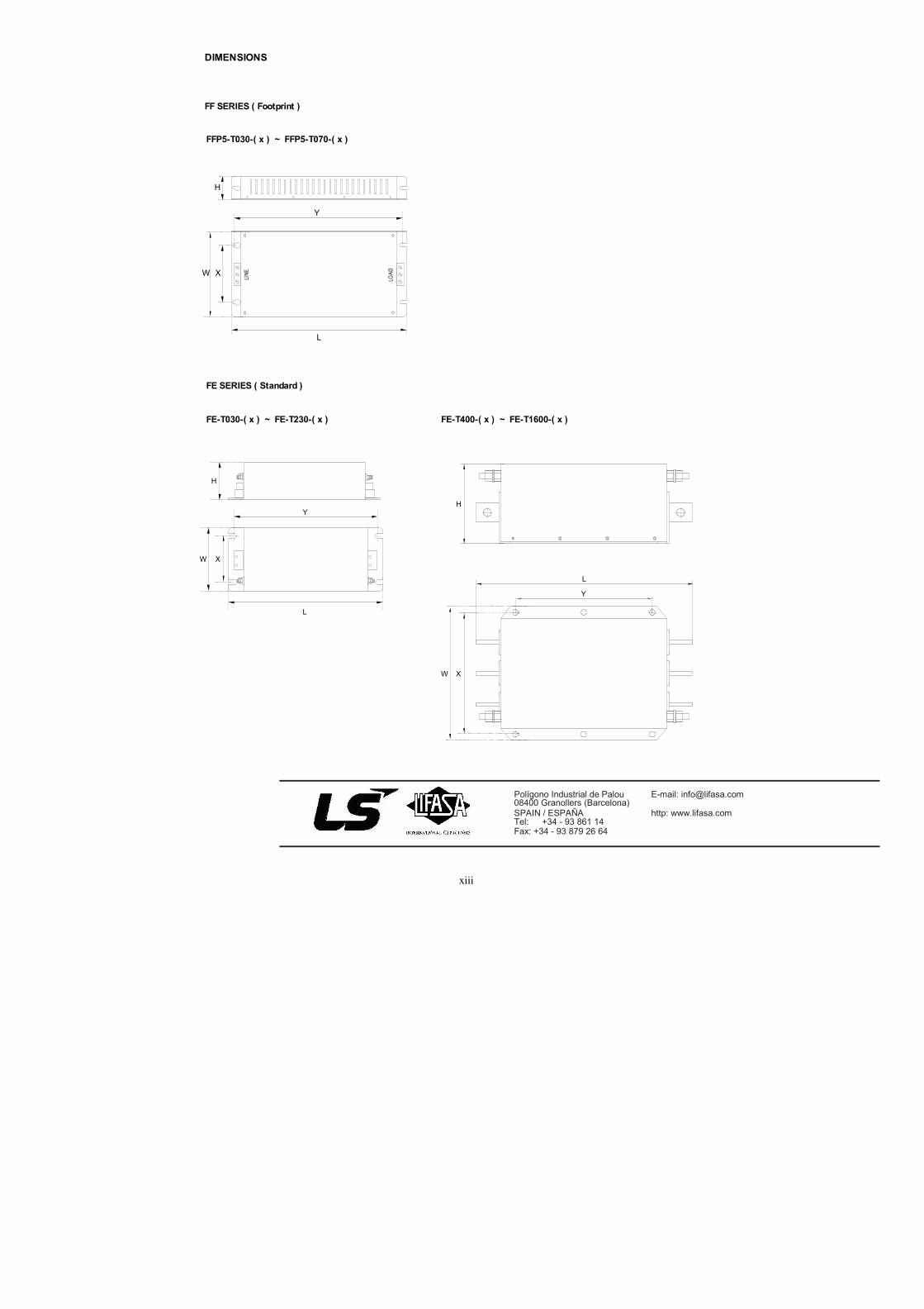
xiii
Polígono Industrial de Palou08400 Granollers (Barcelona)SPAIN / ESPAÑATel: +34 - 93 861 14
Fax: +34 - 93 879 26 64
E-mail: [email protected]
http: www.lifasa.com
Y
L
XW
H
LOAD
LINE
Y
L
XW
H
FE SERIES ( Standard )
FF SERIES ( Footprint )
XW
Y
L
DIMENSIONS
FE-T030-( x ) ~ FE-T230-( x ) FE-T400-( x ) ~ FE-T1600-( x )
FFP5-T030-( x ) ~ FFP5-T070-( x )
H
xiv
Maker LSIS Co., Ltd. Installation (Start-up)
Date
Model No. SV-iP5A Warranty
Period
Customer Information
Name
Address
Tel.
Sales Office (Distributor)
Name
Address
Tel.
Warranty period is 12 months after installation or 18 months after manufactured when the installation
date is unidentified. However, the guarantee term may vary on the sales term.
IN-WARRANTY service information
If the defective part has been identified under normal and proper use within the guarantee term, contact your
local authorized LS distributor or LS Service center.
OUT-OF WARRANTY service information
The guarantee will not apply in the following cases, even if the guarantee term has not expired.
Damage was caused by misuse, negligence or accident.
Damage was caused by abnormal voltage and peripheral devices’ malfunction (failure).
Damage was caused by improper repair or altering by other than LS authorized distributor or
service center.
Damage was caused by an earthquake, fire, flooding, lightning, or other natural calamities.
When LS nameplate is not attached.
When the warranty period has expired.
Warranty

xv
Revision History
No. Date Edition Changes
1 October, 2004 First Release -
2 June, 2005 2 nd
Edition CI changed
3 June, 2006 3 rd
Edition Revised for new kW(HP) ratings
4 November, 2006 4 th
Edition S/W Version up (V0.4)
5 December, 2006 5th Edition Contents added and revised
6 June, 2008 6th Edition Contents added and revised
7 April, 2009 7th Edition New Controller contents added
8 April, 2011 8th Edition 600V Drive added